

Page 1
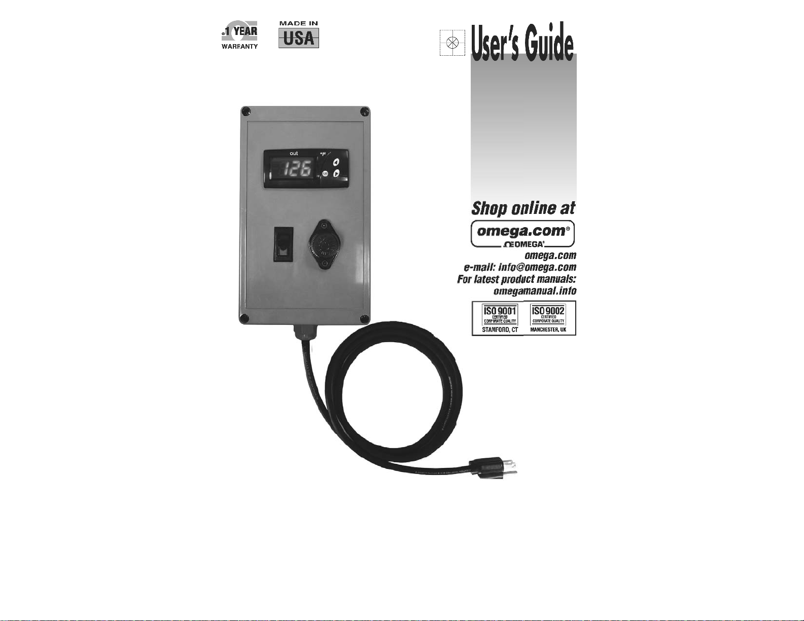
CN-TOT-A Series
Portable Thermocouple Temperature
Controller
Page 2
TABLE OF CONTENTS
IMPORTANT SAFETY INSTRUCTIONS
Introduction...................................................................
Safety Alert Symbol.......................................................
Important Safety Instructions……………......................
Specifi cations................................................................
Installation / Operation Instructions.……......................
Programming Instructions.............................................
Troubleshooting Guide……………………………..........
Notes ...........................................................................
Warranty........................................................................
2
2
3
4
4
5
6
7
BACK
INTRODUCTION
OMEGALUX® CN-TOT Portable Thermocouple Temperature Controllers
are designed for general purpose use in indoor environments to control the
temperature of small tanks, drums, pipes, or other applications requiring
automatic control.
SAFETY ALERT SYMBOL
Immediate hazards which WILL result in severe
personal injury or death
The symbol above is used to call your attention
to instructions concerning your personal safety.
It points out important safety precautions. It
means “ATTENTION! Become Alert! Your
Personal Safety is involved!” Read the
message that follows and be alert to the
possibility of personal injury or death.
Hazards or unsafe practices which COULD result in
severe personal injury or death
A person who has not read and
understood all installation instructions
is not qualifi ed to install this product.
• Do not immerse controller in liquid.
• Keep volatile or combustible material away from
controller when in use.
• Use controller only in approved locations.
• Keep sharp metal objects away from controller.
Failure to observe these warnings may result in
electric shock, risk of fi re, and personal injury.
End User Must Comply to the Following:
• Must be mounted vertically for outdoor use
• Only qualifi ed personnel are allowed to connect
electrical wiring.
• All electrical wiring must follow local electrical
codes and highly recommend following NEC
Article 427.
• Final installation / wiring is to be inspected by the
authority who has jurisdication in the area that
the heater and temperature controller is installed.
• The end-user is responsible for providing a
suitable disconnecting device.
• The end-user is responsible for providing
suitable electrical protection device. It is highly
recommended that a ground fault circuit breaker
is used.
Failure to observe these warnings may result in
personal injury or damage to the controller.
• Inspect all components before
use.
• Do not use control and heater if
any component is damaged.
• Do not repair damaged or faulty
controller.
• Do not crush or apply severe
physical stress on any component
of controller, including cord
assembly.
• Power plug must be plugged into
a sheltered outlet.
• Unplug controller when not in use.
• Unplug controller before fuse is
changed.
• Do not change the fuse while
raining or if water can be
splashed into the fuseholder while
the cap is off.
Failure to observe these warnings may
result in personal injury or damage to
the controller.
Hazards or unsafe practices which COULD result in
minor personal injury or property damage.
SAVE THESE INSTRUCTIONS!
Additional copies of this manual are available upon request.
© Copyright 2006 OMEGA ENGINEERING, Inc. All rights reserved. This document may not be copied, photocopied,
2
reproduced, translated, or reduced to any electronic medium or machine-readable form, in whole or in part, without the
prior written consent of OMEGA ENGINEERING, INC
© Copyright 2006 OMEGA ENGINEERING, Inc. All rights reserved. This document may not be copied, photocopied,
reproduced, translated, or reduced to any electronic medium or machine-readable form, in whole or in part, without the
prior written consent of OMEGA ENGINEERING, INC
3
Page 3
SPECIFICATIONS
PROGRAMMING INSTRUCTIONS
• 120 or 240VAC
• 15 amps
• Digital on/off controller
• Units in °F
• Αudible alarm
• Type J thermocouple mini and
standard connector input *
• Αverage accuracy of ±1% FS
• Resolution: 1°
• Hystersis: 5°
• Μounting feet and mounting
bracket kit included
Thermocouple sold separately
*
Part Number Volts Range
CN-TOT-175JF-120V 120 0 to 175°F
CN-TOT-175JF-240 240 0 to 175°F
INSTALLATION / OPERATION INSTRUCTIONS
• Οperating exposure temperatures:
14 to 131°F (-10 to 55°C)
• Storage exposure temperatures:
-4 to 176°F (-20 to 80°C)
• Input power cord 6 feet (1.8m) long
with standard plug:
-120VAC: NEMA 5-15
-240VAC: NEMA 6-15
• Output receptacle:
-120VAC: NEMA 5-15R
-240VAC: NEMA 6-15R
PARAMETER PROGRAMMING
Set Point (SP) is the only parameter the user can access without code
protection.
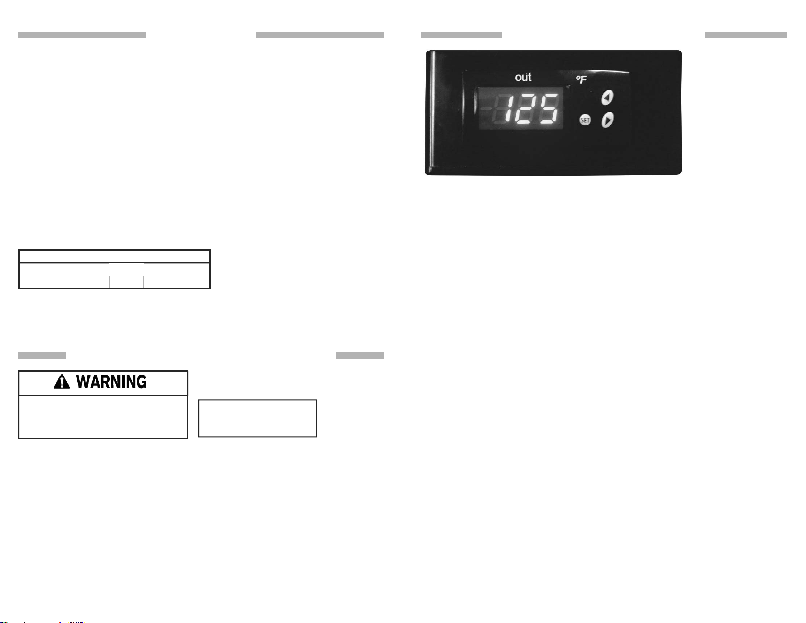
• Press SET. SP text will appear on the display.
• Press SET again. The real value is shown on the display.
• The value can be modifi ed with the UP and DOWN arrows.
• Press SET to enter any new values.
• Press SET and DOWN at the same time to quit programming or wait one
minute and the display will automatically exit programming mode.
BUZZER
In the event of alarm or error condition, the internal buzzer is activated. To
silence the buzzer, press and hold the SET and Down keys for 2 seconds.
LED INDICATIONS
• OUT = Indicates that the heater is on.
Read and understand this entire
manual before operating this
controller.
VOLTAGE:
120VAC; 240VAC
DISPLAY MESSAGES
In normal operation, the sensor temperature will be shown on the display. In
case of alarm or error, the following messages will be shown:
• Er = Memory Error
Plug heater into the controller and the controller into its power source. Plug
thermocouple into thermocouple jack. Make sure sensing tip is fi rmly attached
• -- = Short-Circuit Probe Error (Disconnects output).
• oo = Open Probe Error (Disconnects output).
to heater. Mount controller using mounting feet. For IBC / tote tank heating
applications, attach controller to IBC / tote tank using hanging bracket kit. Push
power switch “ON”. Refer to “Programming Instructions” for how to program
controller.
CONTROLLER OPERATION:
Once the controller reaches set point, the heater will turn off and will not turn on
again until the temperature falls 5°F below the set point.
The controller will sound an audible alarm if the temperature at the sensor
exceeds 15°F above the set-point.
© Copyright 2006 OMEGA ENGINEERING, Inc. All rights reserved. This document may not be copied, photocopied,
4 5
reproduced, translated, or reduced to any electronic medium or machine-readable form, in whole or in part, without the
prior written consent of OMEGA ENGINEERING, INC
© Copyright 2006 OMEGA ENGINEERING, Inc. All rights reserved. This document may not be copied, photocopied,
reproduced, translated, or reduced to any electronic medium or machine-readable form, in whole or in part, without the
prior written consent of OMEGA ENGINEERING, INC
Page 4

TROUBLESHOOTING GUIDE
NOTES
Please read this guide prior to contacting OMEGA. This guide is designed to
answer the most commonly asked questions. If you are unable to identify the
problem or need additional assistance, please contact us at 1-800-USA-HEAT.
Controller does not function
1. Check fuse: Unplug the unit from its power source. Remove the fuse and
check its continuity. If the fuse is defective, replace it with an Class CC 15 amp
fuse. Fuses may be obtained from most electrical supply houses.
2. Check power source: Using a voltmeter, test the power source and assure
correct voltage is present.
3. Check thermocouple: Using a thermocouple meter, test the sensor to assure
proper function.
____________________________________________________________
____________________________________________________________
____________________________________________________________
____________________________________________________________
____________________________________________________________
____________________________________________________________
____________________________________________________________
____________________________________________________________
____________________________________________________________
____________________________________________________________
____________________________________________________________
____________________________________________________________
____________________________________________________________
____________________________________________________________
____________________________________________________________
____________________________________________________________
____________________________________________________________
© Copyright 2006 OMEGA ENGINEERING, Inc. All rights reserved. This document may not be copied, photocopied,
6 7
reproduced, translated, or reduced to any electronic medium or machine-readable form, in whole or in part, without the
prior written consent of OMEGA ENGINEERING, INC
© Copyright 2006 OMEGA ENGINEERING, Inc. All rights reserved. This document may not be copied, photocopied,
© Copyright 2006 OMEGA ENGINEERING, Inc. All rights reserved. This document may not be copied, photocopied,
reproduced, translated, or reduced to any electronic medium or machine-readable form, in whole or in part, without the
reproduced, translated, or reduced to any electronic medium or machine-readable form, in whole or in part, without the
prior written consent of OMEGA ENGINEERING, INC
prior written consent of OMEGA ENGINEERING, INC
Page 5
M-4326A/0406
PN: 11692-01 Rev 0
 Loading...