

Page 1
MADE IN
User’s Guide
Shop online at
omega.com
®
e-mail: [email protected]
For latest product manuals:
www.omegamanual.info
CNi-CB120/240 SERIES
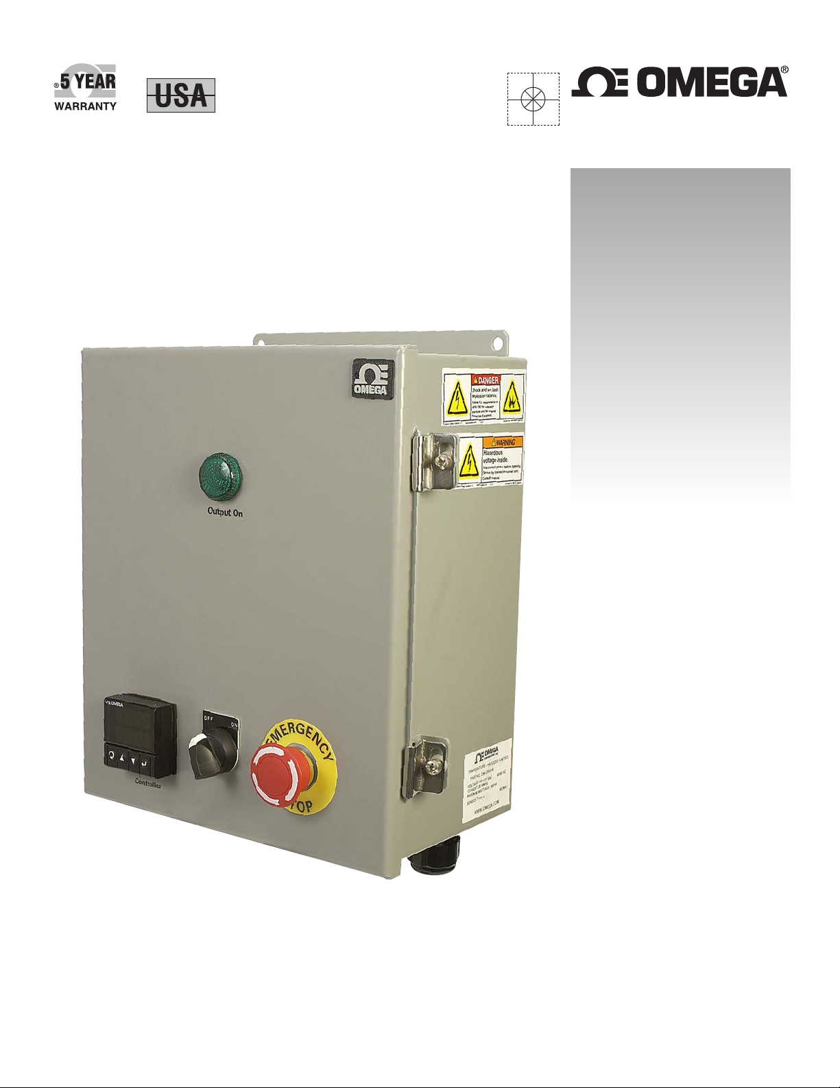
Industrial Controller Panels
Page 2

omega.com [email protected]
Servicing North America:
U.S.A.: Omega Engineering, Inc., One Omega Drive, P.O. Box 4047
Stamford, CT 06907-0047 USA
Toll-Free: 1-800-826-6342 (USA & Canada only)
Customer Service: 1-800-622-2378 (USA & Canada only)
Engineering Service: 1-800-872-9436 (USA & Canada only)
Tel: (203) 359-1660 Fax: (203) 359-7700
e-mail: [email protected]
For Other Locations Visit omega.com/worldwide
The information contained in this document is believed to be correct, but OMEGA accepts no liability for any errors it contains, and reserves
the right to alter specifications without notice.
WARNING: These products are not designed for use in, and should not be used for, human applications.
Page 3

Table of Contents
Section Page
Section 1 Introduction .......................................................................................... 1-1
WARNINGS
1.1 Precautions
1.2 Safety Warnings and IEC Symbols
CNi-CB120/240 Series
Industrial Controller Panels
.......................................................................................................... 1-1
..................................................................................................... 1-1
.............................................................. 1-2
Section 2 Hardware
2.1 Unpacking and Inspection
2.2 Included Items
2.3 CNi-CB120 and CNi-CB240 Labels
2.4 CNi-CB120 and CNi-CB240 Mounting Dimensions
2.5 CNi-CB120 Components
2.6 CNi-CB240 Components
Section 3 Installation and Wiring
3.1 Connections
3.1.1 Rewiring for 4 Wire 100 Ohm RTD Input ......................................... 3-2
3.1.2 Programming the Controller for 4 Wire 100 Ohm RTD .................. 3-6
3.2 Wiring Schematics
3.2.1 CNi-CB120 Wiring ............................................................................... 3-8
3.2.2 CNi-CB240 Wiring ............................................................................. 3-10
Section 4 Spare Parts
Section 5 Specications
............................................................................................. 2-1
.......................................................................... 2-1
............................................................................................... 2-1
............................................................ 2-2
................................ 2-2
.............................................................................. 2-3
.............................................................................. 2-5
..................................................................... 3-1
.................................................................................................... 3-1
........................................................................................ 3-8
........................................................................................... 4-1
...................................................................................... 6-1
i
Page 4

CNi-CB120/240 Series
Industrial Controller Panels
List of Figures
Section Figure Description .............................................................. Page
Section 1 1-2 IEC Symbols ........................................................................ 1-2
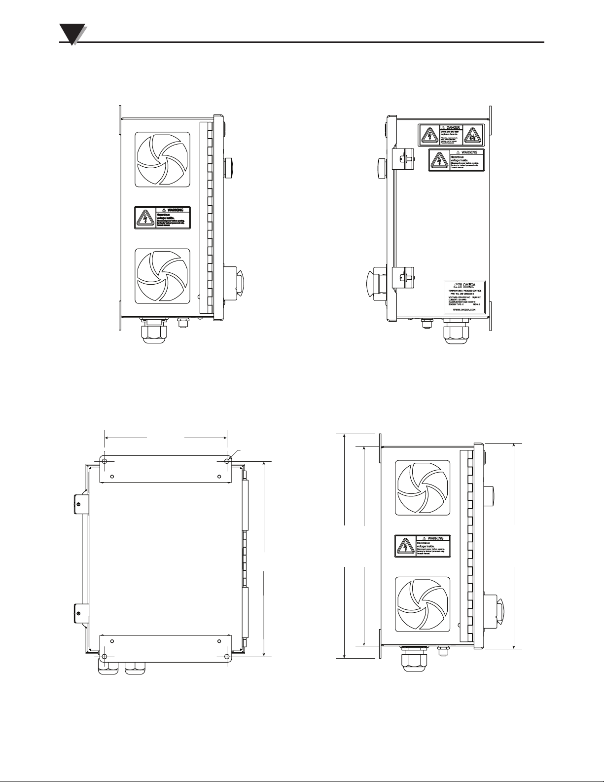
Section 2 2-1 CNi-CB120 and CNi-CB240 Labels (Left View) ............. 2-2
2-10 CNi-CB240 Components Front View (Open) ................. 2-5
2-11 CNi-CB240 Components Bottom View ........................... 2-6
2-2 CNi-CB120 and CNi-CB240 Labels (Right View) .......... 2-2
2-3 CNi-CB120 and CNi-CB240
Mounting Dimensions (Rear View) ............................ 2-2
2-4 CNi-CB120 and CNi-CB240
Mounting Dimensions (Side View) ............................ 2-2
2-5 CN-CB120 and CBi-CB240
Mounting Dimensions (Bottom View) ....................... 2-3
2-6 CNi-CB120 Components Front View (Closed) .............. 2-3
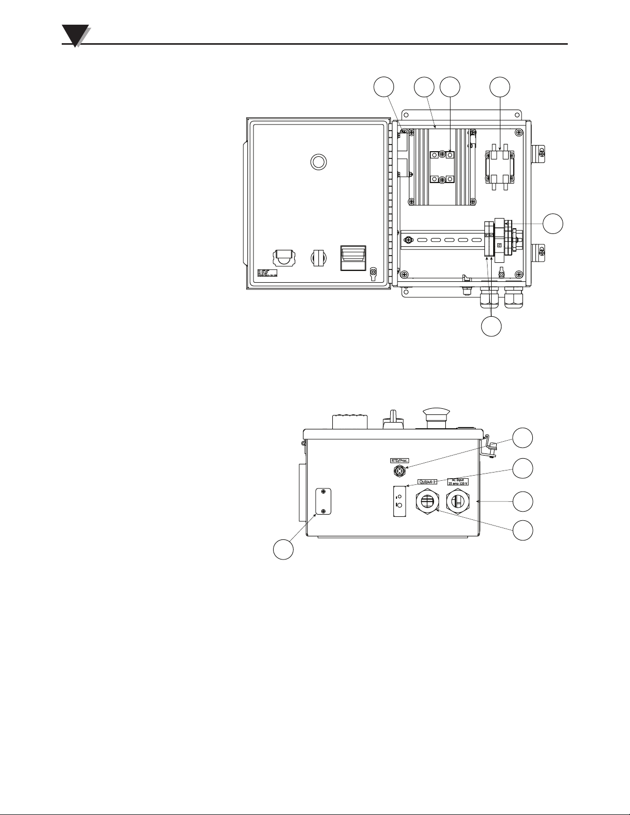
2-7 CNi-CB120 Components Front View (Open) ................. 2-4
2-8 CNi-CB120 Components Bottom View ........................... 2-4
2-9 CNi-CB240 Components Front View (Closed) .............. 2-5
Section 3 3-1 From the Factory ................................................................ 3-2
3-2 Remove the Thermocouple Wire From 1 and 2 ............. 3-3
3-3 Unclip the M12 Connector Wire ...................................... 3-3
3-4 Remove Wire Nut ............................................................... 3-4
3-5 Install Wires Per Wiring Diagram ................................... 3-4
3-6 Place Wire Nut on T/C Wire ............................................ 3-5
3-7 Place Wire Into Clip To Secure It. Close Box and
Secure Box Cover Screws ............................................. 3-5
3-8 Flow Chart ........................................................................... 3-6
3-9 CNi-CB120 Output Wiring ............................................... 3-8
3-10 CNi-CB120 Internal Wiring .............................................. 3-9
3-11 CNi-CB240 Output Wiring ............................................. 3-10
3-10 CNi-CB240 Internal Wiring ............................................ 3-11
ii
Page 5

Section 1 - Introduction
The CNI-CB120/240 series Industrial Controller Panel is ideal for light industrial
use and applications requiring temperature measurement and control. The CNICB120/240 features both a Thermocouple and an M-12 Female input connection.
The CNI-CB120/240 can be congured by the user for use with a thermocouple,
RTD, Voltage or Current signal. These controllers are factory congured and
calibrated for Thermocouples. It is important that the user read this manual
and additional manuals outlined in Section 2.2 completely and follow all safety
precautions in all manuals before operating your unit.
• This unit contains 120V or 240V which can cause injury or
death within the enclosure. Installation and troubleshooting of
input, output, and internal circuitry should be performed by
qualied personnel only.
• Hazardous voltages are present on the internal circuitry of
the Temperature Controller.
• Disconnect power before attempting any inspection or work
on the inside of unit.
• Be sure the branch circuit or main disconnect switch is open
or electrical input circuit fuses are removed before attempting
any inspection or work on the inside of unit.
• This control box is designed for inside, dry use only. To
avoid the risk of shock or re DO NOT expose this box to
excessive moisture (ie wash down) or rain. It is not NEMA
rated.
WARNING:
Introduction
1
1.1 Precautions
• Follow all safety precautions and operating instructions outlined in this
manual.
• Keep unit out of reach of all children.
• Do not operate in ammable or explosive environments.
• Never operate with a power cord that is not properly rated for use with your
unit.
• Remove and or disconnect main power cord before attempting any
maintenance or fuse replacement.
• Do not connect and or operate this unit to a non-grounded, non-polarized
outlet or power source.
• This product is not designed for use in human, medical, nuclear, or other
safety critical applications.
• This product is not for use in damp or wet environments. Do not operate
controller in an area where it can get wet or sprayed.
• Do not plug the equipment into a receptacle with wet hands. Ensure hands are
dry before handling the electrical cord and connecting to power.
1-1
Page 6

1
Introduction
There are no user serviceable parts inside your device.
Attempting to repair or service your unit may void your
warranty.
1.2 Safety Warnings and IEC Symbols
This device is marked with international safety and hazard symbols in
accordance with EN61010-1. It is important to read and follow all precautions
and instructions in this manual before operating or commissioning this device as
it contains important information relating to safety and EMC. Failure to follow
all safety precautions may result in injury and or damage to your controller.
Use of this device in a manor not specied by the manufacturer may impair
protection devices and safety features provided by the unit.
IEC symbols Description
NOTE:
Caution, refer to accompanying documentation
EU’s Waste Electrical and Electronic Equipment
Compliance
Figure 1-1. IEC Symbols
1-2
Page 7

Section 2 – Hardware
2.1 Unpacking and Inspection
Remove the packing slip and verify that you have received everything listed.
Inspect the container and equipment for signs of damage as soon as you receive
the shipment. Note any evidence of rough handling in transit. Immediately
report any damage to the shipping agent. The carrier will not honor damage
claims unless all shipping material is saved for inspection. After examining
and removing the contents, save the packing material and carton in the event
reshipment is necessary.
If you have any questions about the shipment, please call our Customer Service
Department at:
1-800-622-2378 or 203-359-1660.
We can also be reached on the Internet at omega.com e-mail: [email protected]
2.2 Included Items
The following items are supplied with your unit:
Hardware
2
• CNI-CB120 –or– CNI-CB240 series Industrial Controller Panel (1 each)
• SC-GG-(*)-30-36 Spool Cap Thermocouple (1 each)
• Spare 100 mA control fuse (1 each)
• Spare 25 Amp output fuse (1 each)
• Spare 1 Amp SSR fuse (1 each)
• This Users Guide and CNI Controller Manual #M3355 (1 each),
• Quick Start Manual #MQS3355 (1 each)
• Communications Manual #M-3629 (1 each) with Ethernet models only
2-1
Page 8
2
Hardware
Section 2.3 CNi-CB120 and CNi-CB240 Labels
Figure 2-1. CNi-CB120 & CNi-CB240 Labels Figure 2-2. CNi-CB120 & CNi-CB240 Labels
Left
View Right View
Section 2.4 CNi-CB120 and CNi-CB240 Mounting Dimensions
203.2 (8.00)
Ø7.9 (Ø.31)
4X
323.9
(12.75)
342.9 (13.50)
304.8 (12.00)
314.3 (12.38)
DIMENSIONS: mm (in)
DIMENSIONS: mm (in)
Figure 2-3. CNi-CB120 & CNi-CB240 Figure 2-4. CNi-CB120 & CNi-CB240
Mounting Dimensions (Rear View) Mounting Dimensions (Side View)
2-2
Page 9
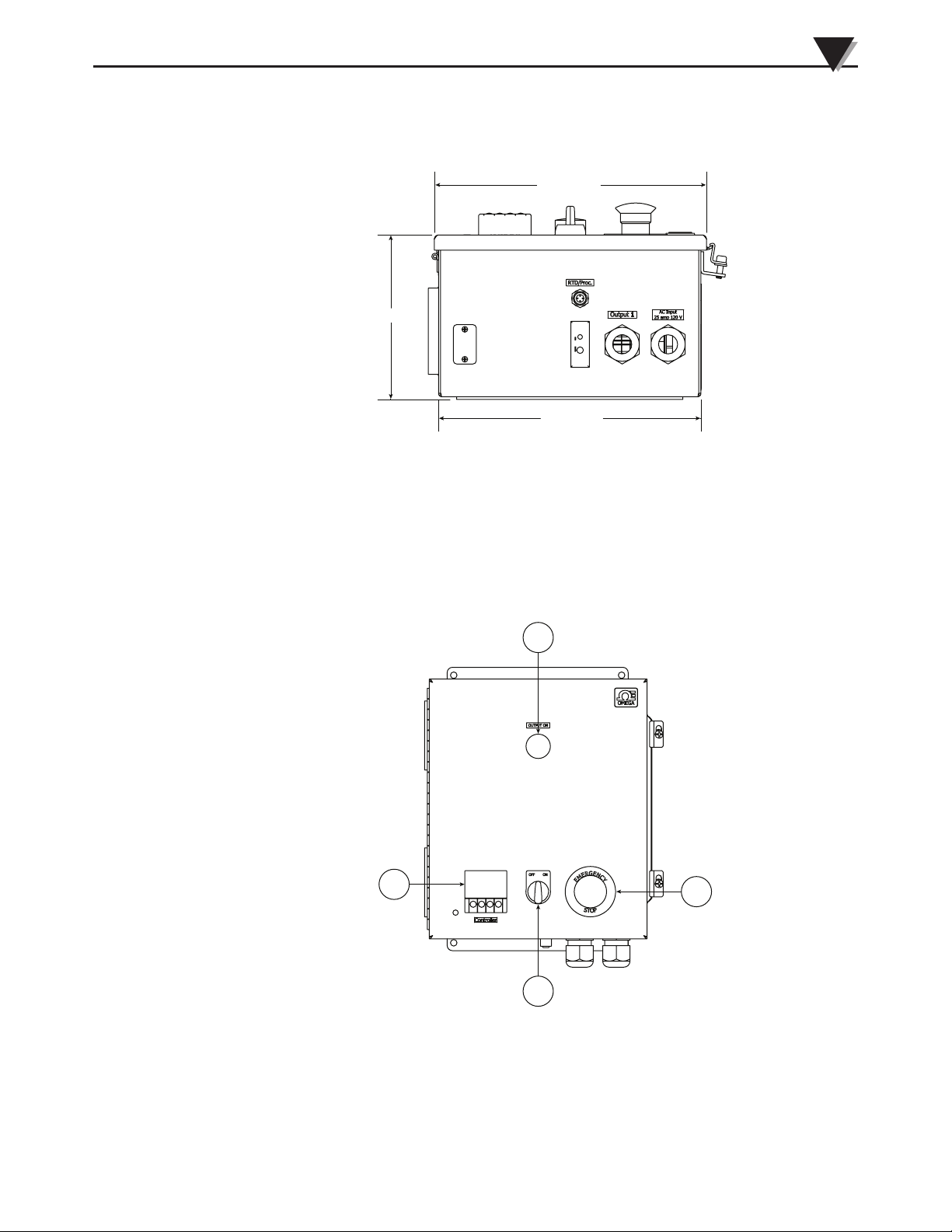
6.27 (159.3)
10.38 (263.5)
Hardware
2
10.00 (254.0)
DIMENSIONS: mm (in)
Figure 2-5. CNi-CB120 & CNi-CB240
Mounting Dimensions (Bottom View)
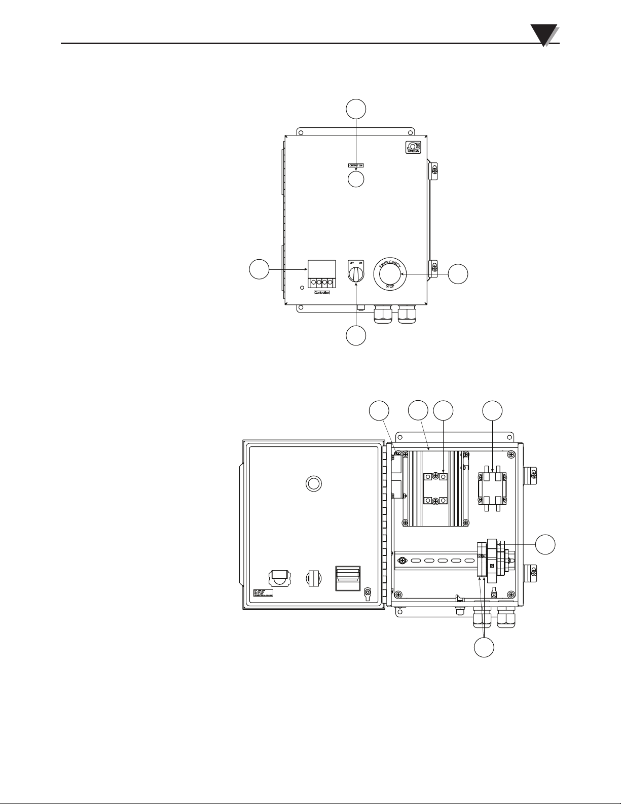
Section 2.5 CNi-CB120 Components
2
1. (Omegamation No.
CNI16D43)
2. Indicator lamp, main
power on
3. Emergeny stop switch
4. On/off switch
Figure 2-6. CNi-CB120 Components
1
3
4
Front View (Closed)
2-3
Page 10
2
Hardware
5. Cooling fan
6. Heat sink (Omegamation no.
FHS-2)
7. Solid state relay, 25A continuous (Omegamation no.
SSRL240DC25)
8. Contractor 1 pole, 30
amp (Omegamation no.
C25CNB130A)
9. Fuse block, din rail mount, 25A
(Omegamation no. ASK-4-1)
10. Fuse block, din rail mount, 1A
(Omegamation no. ASK-2S)
5
6
Figure 2-7. CNi-CB120 Components
Front View (Open)
7
8
9
10
Figure 2-8.
CNi-CB120
11. RTD/Process input, M12
12. TC input (Omegamation no.
UPJ-*-F
13. Power in
14. Power out
15. Ethernet connection (optional)
11
12
13
14
15
Components
Bottom View
2-4
Page 11
Section 2.6 CNi-CB240 Components
Hardware
2
2
1. (Omegamation no.
CNI16D43)
2. Indicator lamp, main
power on
3. Emergeny stop switch
4. On/off switch
5. Cooling fan
6. Heat sink (Omegamation no.
FHS-2)
7. Solid state relay, 25A
Continuous (Omegamation no.
SSRL240DC25)
8. Contractor, 1 pole, 30
amp (Omegamation no.
C25CNB130A)
9. Fuse block, din rail mount, 25A
(Omegamation no. ASK-4-1)
10. Fuse block, din rail mount, 1 A
(Omegamation no. ASK-2S)
1
4
Figure 2-9. CNi-CB240 Components
Bottom Front View (Closed)
5
3
6
7
8
9
Figure 2-10. CNi-CB240 Components
Front View (Open)
10
2-5
Page 12
2
Hardware
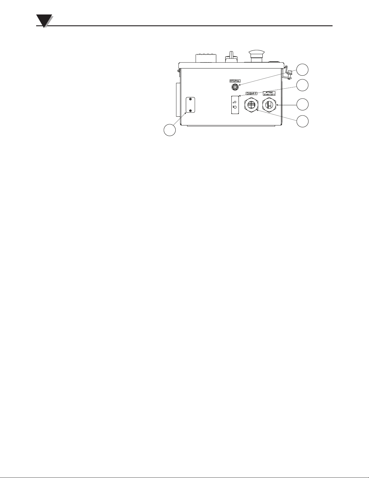
11
11. RTD/Process input, M12
12. TC input (Omegamation no.
UPJ-*-F
13. Power in
14. Power out
15. Ethernet connection (optional)
12
13
14
15
Figure 2-11. CNi-CB240 Components
Bottom View
2-6
Page 13

Section 3 - Installation and Wiring
Section 3.1 Connections
Installation and troubleshooting of input, output, and internal
circuitry should be performed by qualied personnel only
It is very imp ortant to read and understand the controller
manual before attempting to apply power to this control
box. The controller has been precongured for thermocouple
operation. Should the user desire to use another input such
as RTD or Process using the M-12 connector provided, the
user will need to remove the thermocouple wires and connect
the wires from the M-12 connector on the back of the CNI
Controller. The user will also need to recongure the input
settings to congure the controller for the correct input type
(RTD or Process (Voltage or Current) input). See the Controller
Manual #M3355 for additional instructions. An example of a
4 wire RTD connection has been given later in this manual.
Installation and Wiring
WARNING:
NOTE:
5
The CNI-CB120 is designed to operate using standard 120V, 60Hz.
The CNI-CB240 is designed to operate using standard 240V, 60Hz.
1) Attach properly sized input power cable thru bottom input cable gland,
and assemble to labeled input fuse block. (DO NOT CONNECT POWER IF
CHANGING INPUT TYPES).
2) If using a thermocouple, plug the thermocouple into the jack provided on the
bottom of the unit.
3) If using RTD or Process Control, the user will need to rewire the input
connections on the back of the back of the controller. MAKE SURE THE POWER
IS NOT CONNECTED! (see Section 2.4.1 below for an example of converting it
for 4 wire RTD input)
4) Attach properly sized output power cable thru bottom output cable gland, and
assemble to labeled output fuse block.
5) The fuses have been preinstalled. Caution must be taken when replacing fuses
because high voltage may be present at various locations within control box.
6) After all of the connections have been made AND THE DOOR IS SECURED, the
user may turn the unit on. Turning on the power switch will turn the controller
on. The outputs will be off at this point. The user can now program the controller
for RTD or Process inputs if needed.
7) The set points can now be adjusted for each output.
8) When the set points are adjusted, pressing the down arrow twice will return the
controller to run mode and it will begin to control.
3-1
Page 14
3
Installation and Wiring
NOTE:
IT IS VERY IMPORTANT TO READ AND UNDERSTAND
THE CONTROLLER MANUALS BEFORE OPERATING THE
CONTROL BOX.
The CNI Temperature/Process Controller has a lot of functionality. The menu
structure in the quick start manual gives the user an easy understanding of how
to move thru the settings in the controller. Some of the functions are not enabled
for this controller.
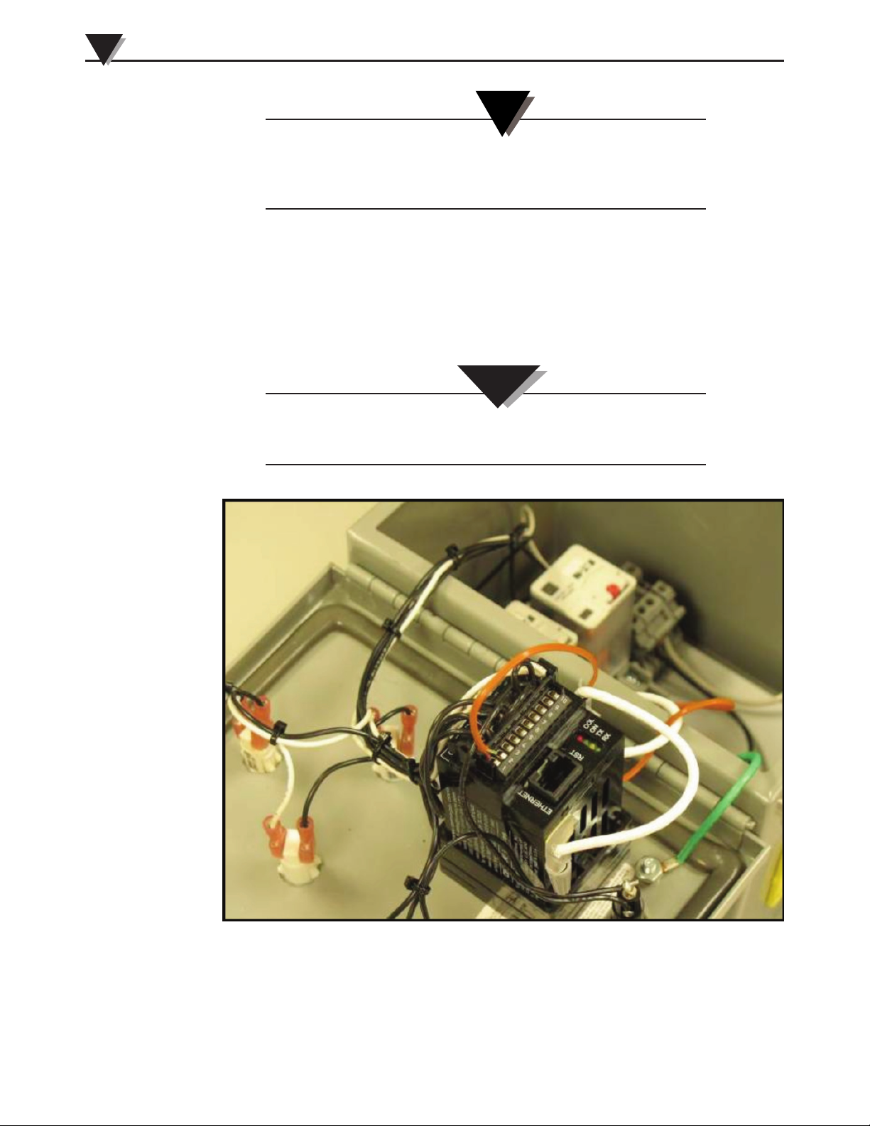
Section 3.1.1 Rewiring for 4 Wire 100 Ohm RTD Input
WARNING:
Shock hazard, Disconnect the power cable from the power
source before rewiring.
3-2
Figure 3-1. From The Factory
Page 15
Installation and Wiring
3
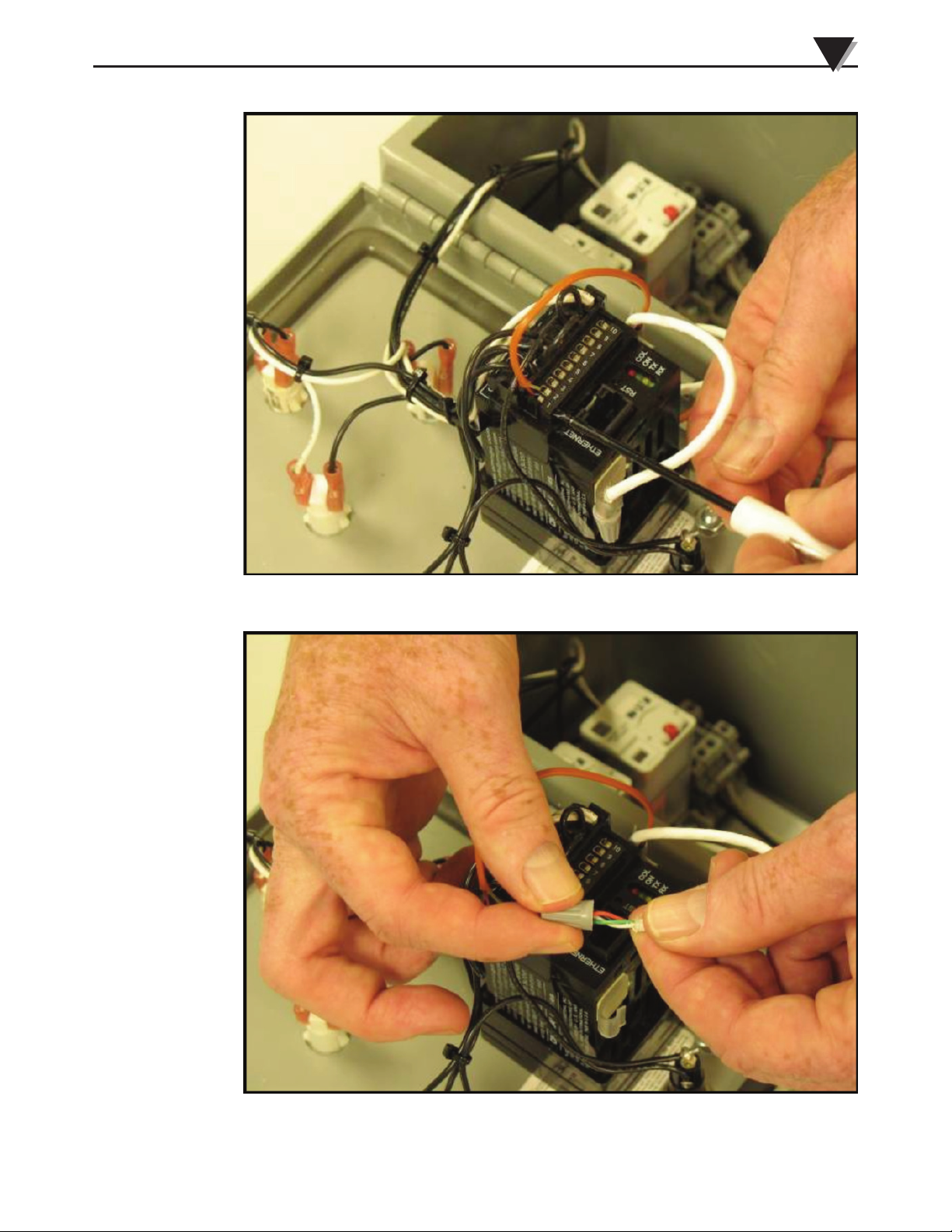
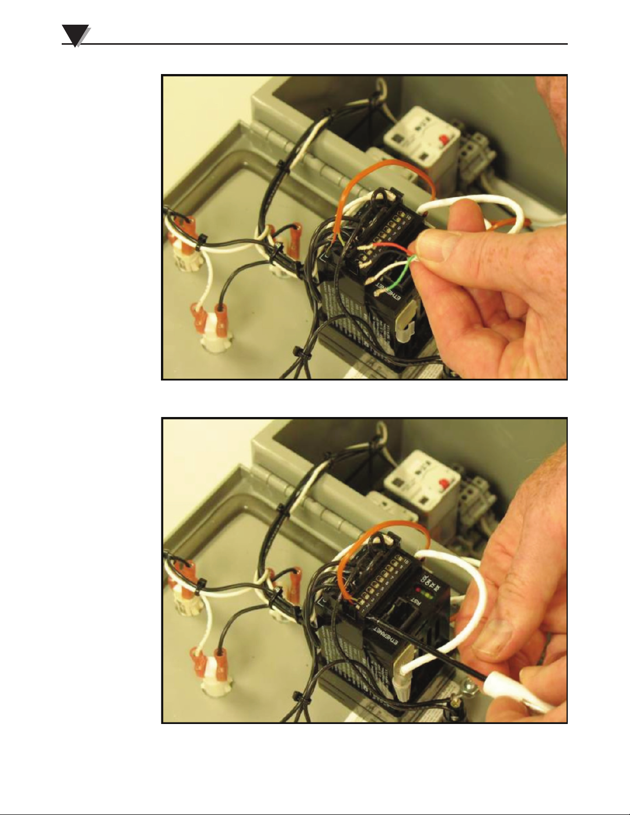
Figure 3-2. Remove The Thermocouple Wire From 1 and 2
Figure 3-3. Unclip the M12 Connector Wire
3-3
Page 16
3
Installation and Wiring
Figure 3-4. Remove Wire Nut
3-4
Figure 3-5. Install Wires Per Wiring Diagram
Page 17
Installation and Wiring
3
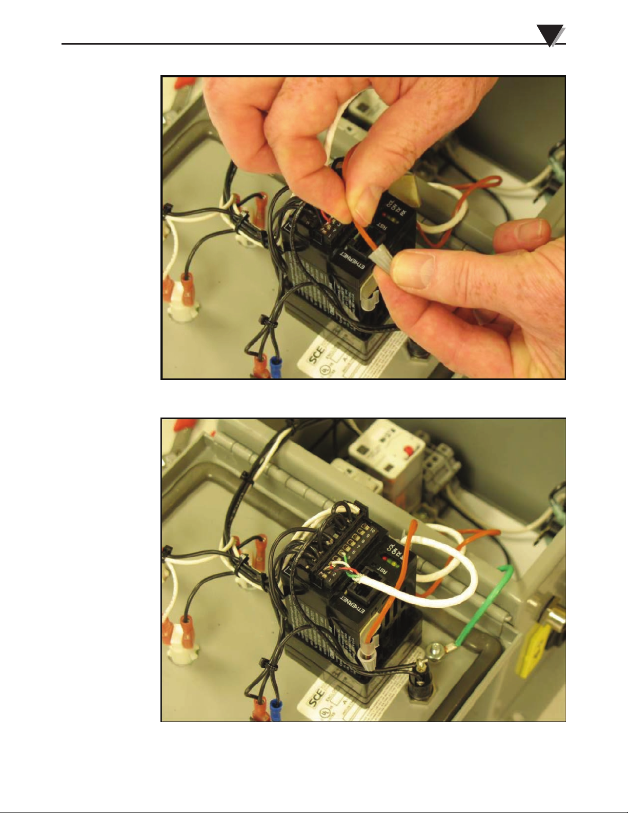
Figure 3-6. Place Wire Nut on T/C Wire
Figure 3-7. Place Wire Into Clip To Secure It. Close Box And Secure Box Cover Screws.
3-5
Page 18
3
Installation and Wiring
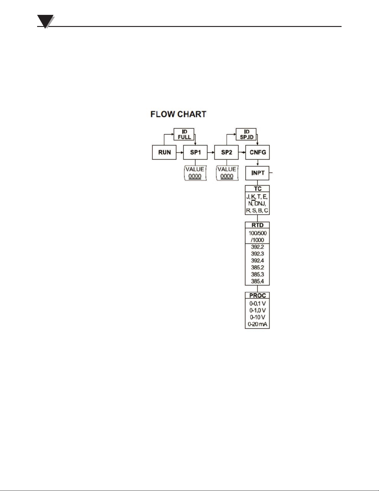
Section 3.1.2 Programming the Controller For 4 Wire 100 Ohm RTD
Now that the controller wiring has been properly connected for 4 wire,100 OHM
usage the controller input needs to be set up to allow the controller to operate
correctly. This is easily accomplished in the example below. Referencing the
Menu diagram at the bottom right of page 2 of the Quick Start Manual the user
will see the input portion below.
3-6
Figure 3-8. Flow Chart
The following steps will set the controller for 4 wire RTD.
1) From the RUN screen press the menu button (far left button). SP1 is displayed
2) Press the menu button again. SP2 is displayed.
3) Press the Menu button again and CNFG is displayed.
4) Press the enter button (far right) and INPT is displayed. This is where the inputs
for the controller are changed and stored.
5) Press the menu Button and TC is displayed. Press the menu button and next RTD
is displayed. Press the enter button to choose this option.
Page 19

Installation and Wiring
3
6) Use the down arrow to select the correct type RTD curve. Most RTD’s are 385 or
European curve. The period 2, 3, or 4 stands for how many wire RTD it is. So in
this case we use 385.4 since we are connecting a 4 wire RTD. (Consult the RTD
manufacture if you are unsure which type RTD you have.)
7) Press enter to save the change.
8) Next RDG is displayed. Press the down arrow 2 times and this will exit the
menu system and return you to RUN mode.
9) You should now be reading the correct temperature on the face is the unit.
3-7
Page 20
3
Installation and Wiring
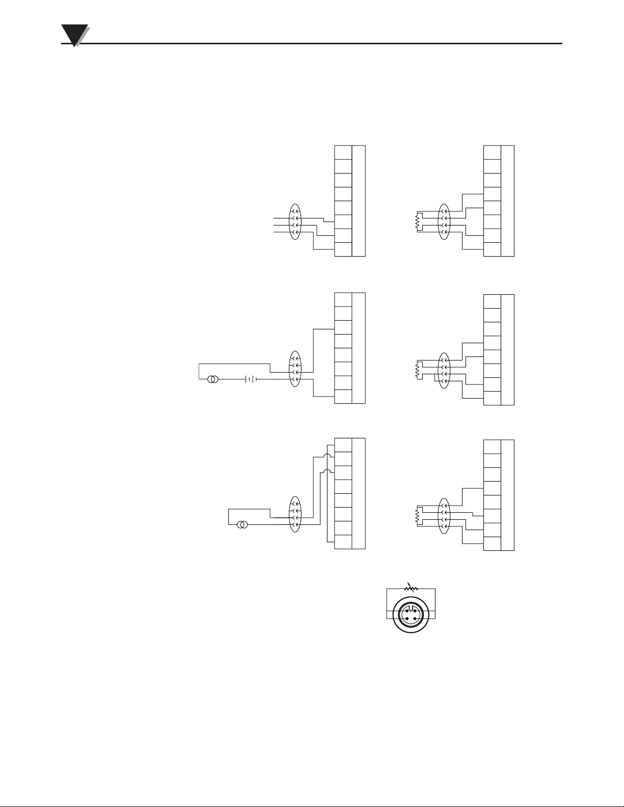
Section 3.2: Wiring Schematics
3.2.1 CNi-CB120 Wiring
(+)
1V OR 10V
(+) (-)
(-)
100 mV
RETURN
(+)
2
3
4
1
2
3
4
1
2
3
4
1
PROCESS
VOLTS
PROCESS
CURRENT
PROCESS
CURRENT
RTD 4 WIRE
(100 OHM)
8
7
6
5
4
INPUT
3
2
1
8
7
6
5
4
INPUT
3
2
1
8
7
6
5
4
INPUT
3
2
1
2
3
4
1
2
3
4
1
2
3
4
1
8
7
6
5
4
INPUT
3
2
1
RTD 3 WIRE
(100 OHM)
8
7
6
5
4
INPUT
3
2
1
RTD 4 WIRE
(1000/500 OHM)
8
7
6
5
4
INPUT
3
2
1
3-8
WIRING FOR RTD M12
CONNECTOR
WHITE
BLUE
2
BROWN
1
BLACK
4
3
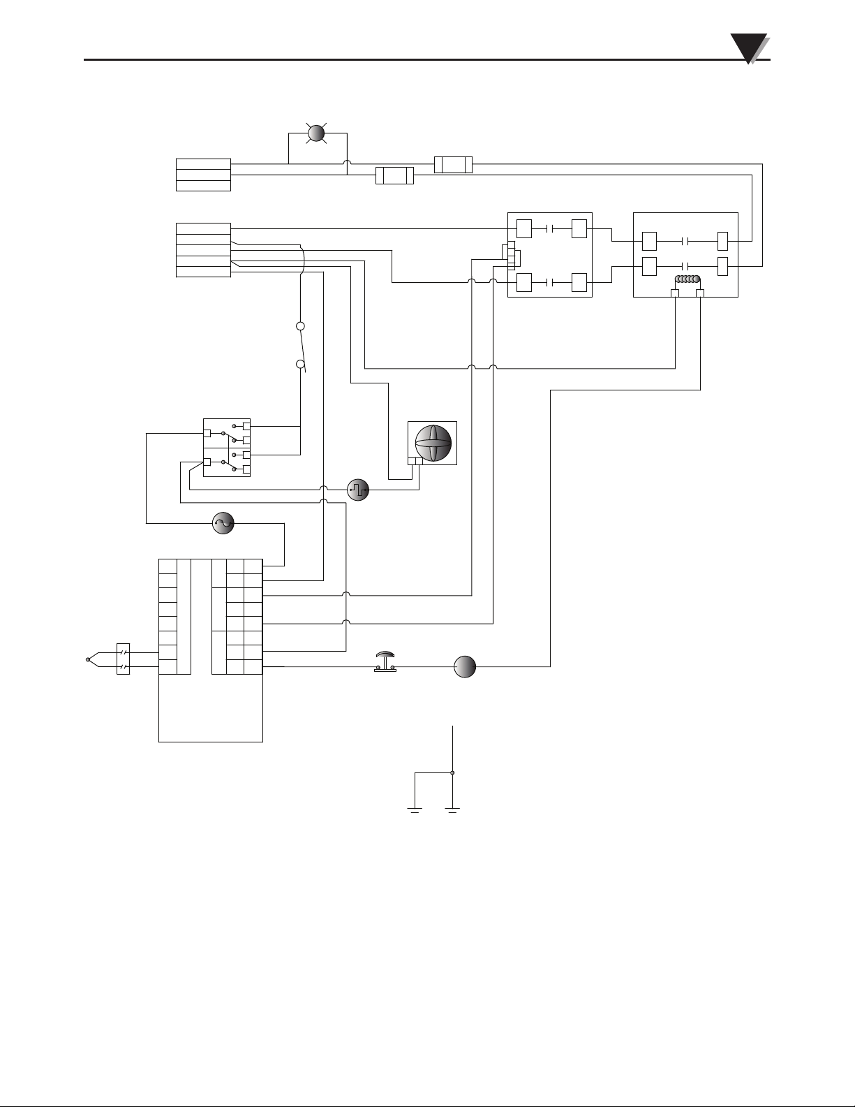
Figure 3-9. CNi-CB120 Output Wiring
Page 21
Installation and Wiring
POWER OUTPUT ON
3
T/C
JACK
PANEL
18 AWG
101E (BK)
(+)
(-)
OUTPUT
L2 120V ac
L1 120V ac
GND
LINE INPUT
L1 120V ac
L1 120V ac
L2 120V ac
L2 120V ac
L2 120V ac
POWER
"ON"
SWITCH
FUSE
100mA
250VAC
8
7
6
5
4
INPUT
3
2
1
TEMPERATURE
PROCESS
CONTROLLER
101C(BK)
10 AWG
L (+)
N (-)
POWER
PUL
RTN
OUTPUT 1OUTPUT 2
NO
NC
C
101C (BK)
18 AWG
DOOR
INTERLOCK
SWITCH
101C (BK)
18 AWG
101C (BK)
18 AWG
101F (BK)
8
7
101G (BK)
6
18 AWG
5
101H (BK)
4
18 AWG
3
101H (BK)
2
18 AWG
1
LIGHT
G
18 AWG
101D (BK)
18 AWG
101H (BK)
18 AWG
100B (WT)
18 AGW
FUSE 25A
250VAC
101C(BK)
10 AWG
101C(BK)
10 AWG
101G (BK)
18 AWG
TEMPERATURE
SWITCH
SELF
RESETTING
120 DEG F
EMERGENCY
STOP
L
N
FUSE 25A
250VAC
FAN
FUSE 1.0A
250VAC
4
3
2
1
DUAL SSR
20 AMP
101C(BK)
10 AWG
101C(BK)
10 AWG
CONTACTOR
2 POLE 20 AMP
A
B
101C(BK)
10 AWG
CONTROL
DOOR
GND TO CONTROL BOX
GROUND STUD
Figure 3-10. CNi-CB120 Internal Wiring
3-9
Page 22
3
Installation and Wiring
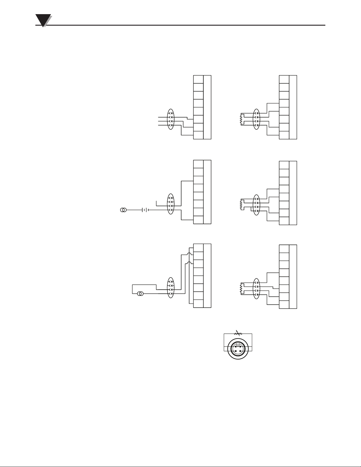
3.2.2 CNi-CB240 Wiring
(+)
1V OR 10V
(+) (-)
(-)
100 mV
RETURN
(+)
PROCESS
VOLTS
8
7
6
5
4
3
2
1
PROCESS
CURRENT
8
7
6
5
4
3
2
1
PROCESS
CURRENT
8
7
6
5
4
3
2
1
INPUT
INPUT
INPUT
RTD 4 WIRE
(100 OHM)
8
7
6
5
4
3
2
1
RTD 3 WIRE
(100 OHM)
8
7
6
5
4
3
2
1
RTD 4 WIRE
(1000/500 OHM)
8
7
6
5
4
3
2
1
INPUT
INPUT
INPUT
3-10
WIRING FOR RTD M12
CONNECTOR
WHITE
BLUE
2
BROWN
1
BLACK
4
3
Figure 3-11. CNi-CB240 Output Wiring
Page 23
T/C
JACK
PANEL
18 AWG
101E (BK)
(+)
(-)
OUTPUT
L2 120V ac
L1 120V ac
GND
LINE INPUT
L1 120V ac
L1 120V ac
L2 120V ac
L2 120V ac
L2 120V ac
SWITCH
8
7
6
5
4
INPUT
3
2
1
TEMPERATURE
PROCESS
CONTROLLER
POWER
"ON"
FUSE
100mA
250VAC
POWER
OUTPUT 1OUTPUT 2
101C(BK)
10 AWG
L (+)
N (-)
PUL
RTN
NO
NC
C
POWER OUTPUT ON
101C (BK)
18 AWG
DOOR
INTERLOCK
SWITCH
101C (BK)
18 AWG
101C (BK)
18 AWG
101F (BK)
8
7
101G (BK)
6
18 AWG
5
101H (BK)
4
18 AWG
3
101H (BK)
2
18 AWG
1
LIGHT
G
18 AWG
101D (BK)
18 AWG
101H (BK)
100B (WT)
18 AGW
18 AWG
FUSE 25A
250VAC
101C(BK)
10 AWG
101C(BK)
10 AWG
101G (BK)
18 AWG
TEMPERATURE
SWITCH
SELF
RESETTING
120 DEG F
EMERGENCY
STOP
L
FUSE 25A
250VAC
FAN
N
FUSE 1.0A
250VAC
4
3
2
1
DUAL SSR
20 AMP
Installation and Wiring
101C(BK)
10 AWG
CONTACTOR
2 POLE 20 AMP
101C(BK)
10 AWG
A
B
3
101C(BK)
10 AWG
CONTROL
DOOR
GND TO CONTROL BOX
GROUND STUD
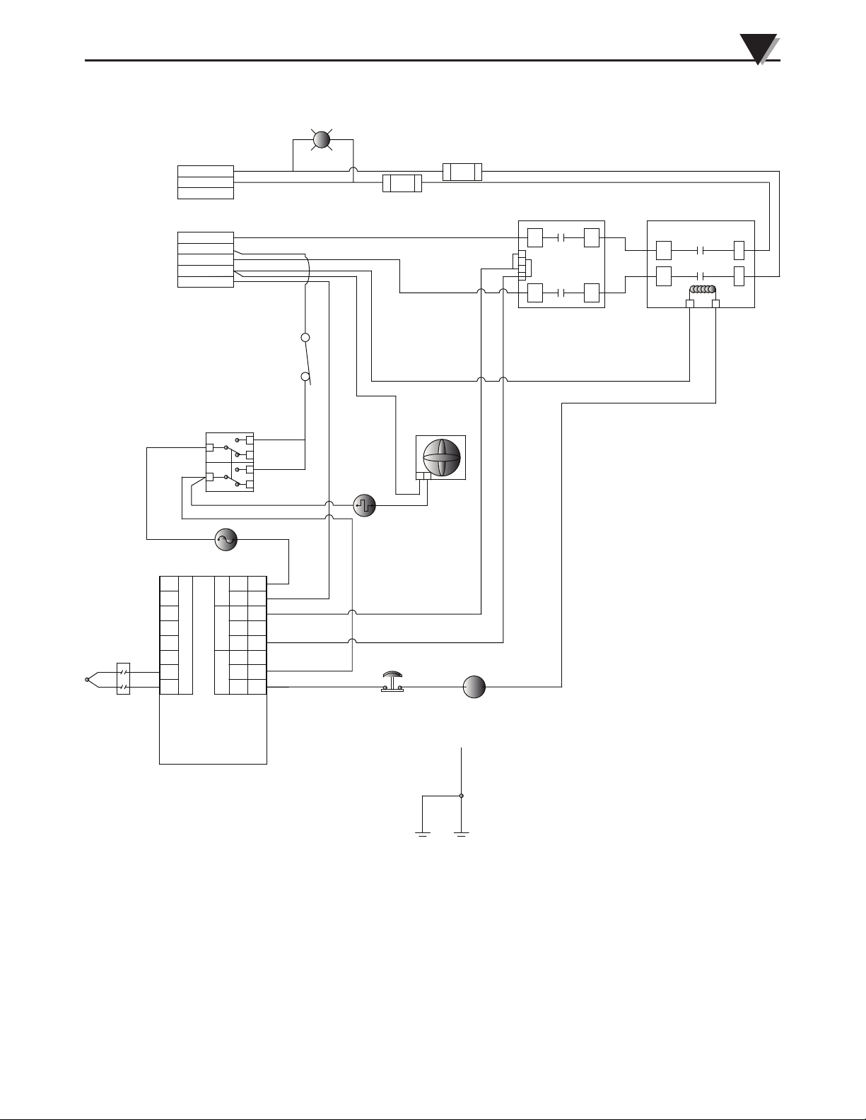
Figure 3-12. CNi-CB240 Internal Wiring
3-11
Page 24

4
Spare Parts
Section 4 - Spare Parts
The following parts are used in the CNI-CB120:
Item Omega PN Omega Catalog Page URL
30 A Contactor, Single Pole C25CNB130A http://www.omega.com/Auto/pdf/C25.pdf
Solid State Relay SSRL240DC25 http://www.omega.com/Temperature/pdf/
SSRL240_660.pdf
Controller Fuse, 100 mA, CB-0051
Fast Acting, 5 x 20 mm
Output Fuse, 25 A, CB-0032
Fast Acting
Relay Fuse, 1 A, BB-0303
Fast Acting, 5 x 20 mm
The following parts are used in the CNI-CB240:
Item Omega PN Omega Catalog Page URL
30 A Contactor, Double Pole C25BNB230B http://www.omega.com/Auto/pdf/C25.pdf
Solid State Relay, Double Pole SSRLDUAL240DC25 http://www.omega.com/Temperature/pdf/
SSRDUAL240.pdf
Controller Fuse, 100 mA, CB-0051
Fast Acting, 5 x 20 mm
Output Fuse, 25 A, CB-0032
Fast Acting
Relay Fuse, 1 A, BB-0303
Fast Acting, 5 x 20 mm
4-1
Page 25

Section 5 - Specifications
CNi-CB120
Specifications
5
Control:
One 120 Vac input that powers one 25 Amp SSR
controlled output
Rating:
120 Vac, 60Hz, 25 Amps (2400 Watts resistive load)
Dimensions: 305 H x 254 W x 152 mm D (12 H x 10 W x 6” D)
Weight: 14 lbs.
Operating Temperature: 0 to 55° (32 to 151°F)
Controller Fuse: 100 mA 250 Vac
Output Fuses: 25 Amps 250 Vac
Contactor Fuse: 1 Amp 250 Vac
For Indoor use only
CNi-CB240:
Control:
One 240 Vac input that powers one 25 Amp SSR
controlled output
Rating:
240 Vac, 60 Hz, 20 Amps (4800 Watts resistive load)
Dimensions: 305 H x 254 W x 152 mm D (12 H x 10 W x 6” D)
Weight: 14 lbs
Operating Temperature: 0 to 55°C (32 to 151°F)
Controller Fuse: 100 mA 250 Vac
Output Fuses: 25 Amps 250 Vac
Contactor Fuse: 1 Amp 250 Vac
For Indoor use only
6-1
Page 26

CNI-CB120/240 Series
Industrial Controller Panels
NOTES:
6-2
Page 27

WARRANTY/DISCLAIMER
OMEGA ENGINEERING, INC. warrants this unit to be free of defects in materials and workmanship for a
period of 61 months from date of purchase. OMEGA’s WARRANTY adds an additional one (1) month
grace period to the normal five (5) year product warranty to cover handling and shipping time. This
ensures that OMEGA’s customers receive maximum coverage on each product.
If the unit malfunctions, it must be returned to the factory for evaluation. OMEGA’s Customer Service
Department will issue an Authorized Return (AR) number immediately upon phone or written request.
Upon examination by OMEGA, if the unit is found to be defective, it will be repaired or replaced at no
charge. OMEGA’s WARRANTY does not apply to defects resulting from any action of the purchaser,
including but not limited to mishandling, improper interfacing, operation outside of design limits,
improper repair, or unauthorized modification. This WARRANTY is VOID if the unit shows evidence of
having been tampered with or shows evidence of having been damaged as a result of excessive corrosion;
or current, heat, moisture or vibration; improper specification; misapplication; misuse or other operating
conditions outside of OMEGA’s control. Components in which wear is not warranted, include but are not
limited to contact points, fuses, and triacs.
OMEGA is pleased to offer suggestions on the use of its various products. However,
OMEGA neither assumes responsibility for any omissions or errors nor assumes liability for
any damages that result from the use of its products in accordance with information provided
by OMEGA, either verbal or written. OMEGA warrants only that the parts manufactured by the
company will be as specified and free of defects. OMEGA MAKES NO OTHER WARRANTIES OR
REPRESENTATIONS OF ANY KIND WHATSOEVER, EXPRESSED OR IMPLIED, EXCEPT THAT OF
TITLE, AND ALL IMPLIED WARRANTIES INCLUDING ANY WARRANTY OF MERCHANTABILITY
AND FITNESS FOR A PARTICULAR PURPOSE ARE HEREBY DISCLAIMED. LIMITATION OF
LIABILITY: The remedies of purchaser set forth herein are exclusive, and the total liability of
OMEGA with respect to this order, whether based on contract, warranty, negligence,
indemnification, strict liability or otherwise, shall not exceed the purchase price of the
component upon which liability is based. In no event shall OMEGA be liable for
consequential, incidental or special damages.
CONDITIONS: Equipment sold by OMEGA is not intended to be used, nor shall it be used: (1) as a “Basic
Component” under 10 CFR 21 (NRC), used in or with any nuclear installation or activity; or (2) in medical
applications or used on humans. Should any Product(s) be used in or with any nuclear installation or
activity, medical application, used on humans, or misused in any way, OMEGA assumes no responsibility
as set forth in our basic WARRANTY/DISCLAIMER language, and, additionally, purchaser will indemnify
OMEGA and hold OMEGA harmless from any liability or damage whatsoever arising out of the use of the
Product(s) in such a manner.
RETURN REQUESTS/INQUIRIES
Direct all warranty and repair requests/inquiries to the OMEGA Customer Service Department.
BEFORE RETURNING ANY PRODUCT(S) TO OMEGA, PURCHASER MUST OBTAIN AN AUTHORIZED
RETURN (AR) NUMBER FROM OMEGA’S CUSTOMER SERVICE DEPARTMENT (IN ORDER TO AVOID
PROCESSING DELAYS). The assigned AR number should then be marked on the outside of the return
package and on any correspondence.
The purchaser is responsible for shipping charges, freight, insurance and proper packaging to prevent
breakage in transit.
FOR WARRANTY RETURNS, please have the
following information available BEFORE
contacting OMEGA:
1. Purchase Order number under which the product
was PURCHASED,
2. Model and serial number of the product under
warranty, and
3. Repair instructions and/or specific problems
relative to the product.
OMEGA’s policy is to make running changes, not model changes, whenever an improvement is possible. This affords
our customers the latest in technology and engineering.
OMEGA is a registered trademark of OMEGA ENGINEERING, INC.
© Copyright 2013 OMEGA ENGINEERING, INC. All rights reserved. This document may not be copied, photocopied,
reproduced, translated, or reduced to any electronic medium or machine-readable form, in whole or in part, without the
prior written consent of OMEGA ENGINEERING, INC.
FOR NON-WARRANTY REPAIRS,
for current repair charges. Have the following
information available BEFORE contacting OMEGA:
1. Purchase Order number to cover the COST
of the repair,
2. Model and serial number of the product, and
3. Repair instructions and/or specific problems
relative to the product.
consult OMEGA
Page 28

Where Do I Find Everything I Need for
Process Measurement and Control?
OMEGA…Of Course!
Shop online at omega.com
TEMPERATURE
MU
Thermocouple, RTD & Thermistor Probes, Connectors, Panels & Assemblies
MU
Wire: Thermocouple, RTD & Thermistor
MU
Calibrators & Ice Point References
MU
Recorders, Controllers & Process Monitors
MU
Infrared Pyrometers
PRESSURE, STRAIN AND FORCE
MU
Transducers & Strain Gages
MU
Load Cells & Pressure Gages
MU
Displacement Transducers
MU
Instrumentation & Accessories
FLOW/LEVEL
MU
Rotameters, Gas Mass Flowmeters & Flow Computers
MU
Air Velocity Indicators
MU
Turbine/Paddlewheel Systems
MU
Totalizers & Batch Controllers
SM
pH/CONDUCTIVITY
MU
pH Electrodes, Testers & Accessories
MU
Benchtop/Laboratory Meters
MU
Controllers, Calibrators, Simulators & Pumps
MU
Industrial pH & Conductivity Equipment
DATA ACQUISITION
MU
Data Acquisition & Engineering Software
MU
Communications-Based Acquisition Systems
MU
Plug-in Cards for Apple, IBM & Compatibles
MU
Data Logging Systems
MU
Recorders, Printers & Plotters
HEATERS
MU
Heating Cable
MU
Cartridge & Strip Heaters
MU
Immersion & Band Heaters
MU
Flexible Heaters
MU
Laboratory Heaters
ENVIRONMENTAL
MONITORING AND CONTROL
MU
Metering & Control Instrumentation
MU
Refractometers
MU
Pumps & Tubing
MU
Air, Soil & Water Monitors
MU
Industrial Water & Wastewater Treatment
MU
pH, Conductivity & Dissolved Oxygen Instruments
M5231/1013
 Loading...