

Page 1
TM
User’s Guide
Shop online at
omega.com
e-mail: [email protected]
For latest product manuals:
www.omegamanual.info
Temperature & Process Controller
with Isolated Analog Output Board
CNi8A & CNi16A Controller Manual
Page 2

omega.com [email protected]
Servicing North America:
U.S.A. Omega Engineering, Inc.
Headquarters: 800 Connecticut Ave. Suite 5N01, Norwalk, CT 06854
Toll-Free: 1-800-826-6342 (USA & Canada only)
Customer Service: 1-800-622-2378 (USA & Canada only)
Engineering Service: 1-800-872-9436 (USA & Canada only)
Tel: (203) 359-1660 Fax: (203) 359-7700
For Other Locations Visit omega.com/worldwide
e-mail: [email protected]
The information contained in this document is believed to be correct, but OMEGA accepts no liability for any errors it contains, and reserves
the right to alter specifications without notice.
Page 3

TABLE OF CONTENTS
Part 1: Introduction............................................................................................2
1.1 Description .................................................................................2
1.2 Safety Considerations ...............................................................3
1.3 Before You Begin .......................................................................4
Part 2: Setup.......................................................................................................5
2.1 Front Panel View ........................................................................5
2.2
1
⁄8
DIN Rear Panel Connections .................................................6
2.3
1
⁄16
DIN Rear Panel Connections................................................7
2.4 Electrical Installation .................................................................8
2.4.1 Fuse Requirement (see Specifications) .......................8
2.4.2 Thermocouple - Input Connection................................9
2.4.3 Two / Three / Four Wire RTD-Hookup.........................10
2.4.4 Process Current - Wiring Hookup...............................11
2.4.5 Process Voltage - Wiring Hookup ...............................11
2.4.6 Wiring Outputs - Wiring Hookup.................................12
Part 3: Operation: Configuration Mode .........................................................15
3.1 Introduction ..............................................................................15
Turning your Instrument On for the First Time
Buttons Functions in Configuration Mode
3.2 Menu Configuration ................................................................16
3.2.1 ID Number .....................................................................17
3.2.2 Set Points......................................................................18
3.2.3 Configuration Menu ....................................................19
3.2.4 Input Type Menu ...........................................................19
Input Type (Thermocouple) ........................................20
Input Type (RTD)...........................................................21
Input Type (Process) ...................................................22
3.2.5 Reading Configuration Menu .....................................22
3.2.6 Alarm 1 Menu ...............................................................26
3.2.7 Alarm 2 Menu................................................................30
3.2.8 Loop Break Time Menu/Field Calibration...................31
3.2.9 Output 1 Menu ..............................................................33
3.2.10 Analog Output (Retransmission) ................................40
3.2.11 Ramp and Soak Menu ..................................................42
3.2.12 ID Code Menu ...............................................................44
3.2.13 Communication Options Menu ...................................46
3.2.14 Display Color Selection Menu.....................................52
Part 4: Specifications ......................................................................................55
4.1
1
⁄8
DIN Mounting ........................................................................58
4.2
1
⁄16
DIN Mounting .......................................................................59
Part 5: Factory Preset Values .........................................................................61
CE Approval Information ................................................................................63
i
Page 4

LIST OF FIGURES:
Figure 2.1
1
⁄8
and
1
⁄16
DIN Front Panel Display.............................................5
Figure 2.2
1
⁄8
and
1
⁄16
DIN Rear View .............................................................5
Figure 2.3
1
⁄8
DIN Rear Panel Input Connections .......................................6
Figure 2.4
1
⁄16
DIN Rear Panel Input Connections ......................................7
Figure 2.5 Main Power Connections ..........................................................8
Figure 2.6 Thermocouple Wiring Hookup..................................................9
Figure 2.7 Two/Three/Four-wire RTD
a) RTD-1000 ohm and 500 ohm Wiring Hookup...................10
b) RTD-100 ohm Wiring Hookup............................................10
Figure 2.8 Process Current Wiring Hookup
(Internal and External Excitation) ...........................................11
Figure 2.9 Process Voltage Wiring Hookup
a) With Sensor Excitation ......................................................11
b) Without Sensor Excitation.................................................11
Figure 2.10 Output Connections:
a) Mechanical Relay and SSR Outputs – Wiring Hookup ...12
b) Pulse and Analog Outputs – Wiring Hookup...................12
Figure 2.11 Analog Output Wiring Hookup................................................12
Figure 2.12 Typical Application...................................................................13
Figure 2.13 Communication Outputs:
a) RS232 Output – Wiring Hookup........................................14
b) RS485 Output – Wiring Hookup........................................14
Figure 2.14 Excitation Output .....................................................................14
Figure 2.15 Snubber Circuits Wiring Hookup............................................14
Figure 3.1 Flow Chart for ID and Set Points Menu..................................16
Figure 3.2 Flow Chart for Configuration Menu........................................19
Figure 3.3 Flow Chart for Input Type Menu .............................................19
Figure 3.4 Flow Chart for Reading Configuration Menu.........................22
Figure 3.5 Flow Chart for Alarm 1 Menu ..................................................26
Figure 3.6 Flow Chart for Alarm 2 Menu ..................................................30
Figure 3.7 Flow Chart for Loop Break Time/Field Calibration ...............31
Figure 3.8 Flow Chart for Output 1 Menu.................................................33
Figure 3.9 Flow Chart for Analog Output Menu.......................................40
Figure 3.10 Flow Chart for Ramp and Soak Menu ....................................42
Figure 3.11 Flow Chart for ID Code Menu..................................................44
Figure 3.12 Flow Chart for Communication Option Menu........................46
Figure 3.13 Flow Chart for Display Color Selection Menu .......................52
LIST OF TABLES:
Table 2.1 Front Panel Annunciators .........................................................5
Table 2.2
1
⁄8
DIN Rear Panel Connector.....................................................6
Table 2.3
1
⁄16
DIN Rear Panel Connector....................................................7
Table 2.4 Fuse Requirement......................................................................8
Table 2.5 TC Wire Color Chart...................................................................9
Table 3.1 Button Function in Configuration Mode ................................15
Table 3.2 Conversion Table .....................................................................25
Table 4.1 Input Properties........................................................................60
Table 5.1 Factory Preset Values..............................................................59
ii
Page 5
NOTES, WARNINGS and CAUTIONS
Information that is especially important to note is identified by following labels:
• NOTE
• WARNING or CAUTION
• IMPORTANT
• TIP
NOTE: Provides you with information that is important to successfully
setup and use the Programmable Digital Meter.
CAUTION or WARNING: Tells you about the risk of electrical shock.
CAUTION, WARNING or IMPORTANT: Tells you of circumstances or
practices that can effect the instrument’s functionality and must refer
to accompanying documents.
TIP: Provides you helpful hints.
1
Page 6

PART 1
INTRODUCTION
1.1 Description
This device can be purchased as monitor (read process value only) or as
a controller.
• The iSeries Temperature/Process controllers offer unparalleled flexibility in
process measurement. Each unit allows the user to select the input type,
from 10 thermocouple types (J, K, T, E, R, S, B, C, N and J DIN), Pt RTDs
(100, 500 or 1000 Ω, with either 385 or 392 curve), analog voltage or current
input. The voltage/current inputs are fully scalable to virtually all engineering
units, with selectable decimal point, perfect for use with pressure, flow or
other process input.
• The temperature and process control can be achieved by using On/Off or
PID control strategy. Control can be optimized with an Auto Tune feature.
The instrument offers a ramp to set point with timed soak period before
switching off the output.
• The iSeries device features a large, three color programmable display with
capability to change a color every time the Alarm is triggered. The standard
features include three outputs with relay, SSR, dc pulse, and isolated analog
voltage or current output. Options include programmable RS232 or RS485
serial communication and excitation. Analog Output is fully scaleable and
configured as retransmission to follow your display. Universal power supply
accepts 90 to 240 Vac. Low voltage power option accepts 24 Vac or 20 to
36 Vdc.
2
Page 7
1.2 Safety Considerations
This device is marked with the International Caution Symbol. It is
important to read this manual before installing or commissioning this
device as it contains important information relating to Safety and EMC
(Electromagnetic Compatibility).
This instrument is a panel mount device protected in accordance with
EN 61010-1:2001, electrical safety requirements for electrical equipment
for measurement, control and laboratory. Installation of this instrument
should be done by qualified personnel. In order to ensure safe operation,
the following instructions should be followed.
This instrument has no power-on switch. An external switch or circuit-
breaker shall be included in the building installation as a disconnecting
device. It shall be marked to indicate this function, and it shall be in close
proximity to the equipment within easy reach of the operator. The switch or
circuit-breaker shall meet the relevant requirements of IEC 947–1 and
IEC 947-3 (International Electrotechnical Commission). The switch shall
not be incorporated in the main supply cord.
Furthermore, to provide protection against excessive energy being drawn
from the main supply in case of a fault in the equipment, an overcurrent
protection device shall be installed.
• Do not exceed voltage rating on the label located on the top of the
instrument housing.
• Always disconnect power before changing signal and power
connections.
• Do not use this instrument on a work bench without its case for safety
reasons.
• Do not operate this instrument in flammable or explosive atmospheres.
• Do not expose this instrument to rain or moisture.
• Unit mounting should allow for adequate ventilation to ensure
instrument does not exceed operating temperature rating.
• Use electrical wires with adequate size to handle mechanical strain
and power requirements. Install without exposing bare wire outside the
connector to minimize electrical shock hazards.
EMC Considerations
• Whenever EMC is an issue, always use shielded cables.
• Never run signal and power wires in the same conduit.
• Use signal wire connections with twisted-pair cables.
• Install Ferrite Bead(s) on signal wires close to the instrument if EMC
problems persist.
Failure to follow all instructions and warnings may result in injury!
3
Page 8

1.3 Before You Begin
Inspecting Your Shipment:
Remove the packing slip and verify that you have received everything
listed. Inspect the container and equipment for signs of damage as soon
as you receive the shipment. Note any evidence of rough handling in
transit. Immediately report any damage to the shipping agent. The carrier
will not honor damage claims unless all shipping material is saved for
inspection. After examining and removing the contents, save the packing
material and carton in the event reshipment is necessary.
Customer Service:
If you need assistance, please call the nearest Customer Service
Department, listed in this manual.
Manuals, Software:
The latest Operation and Communication Manual as well as free
configuration software are available at the website listed on the cover
page of this manual.
For first-time users: Refer to the QuickStart Manual for basic operation
and set-up instructions.
If you have the Serial Communications Option you can easily configure
the controller on your computer.
To Disable Outputs:
To ensure that menu changes are properly stored, Standby Mode should
be used during setup of the instrument. During Standby Mode, the
instrument remains in a ready condition, but all outputs are disabled.
Standby Mode is useful when maintenence of the system is necessary.
When the controller is in "RUN" Mode, push d twice to disable all
outputs and alarms. It is now in "STANDBY" Mode. Push d once more
to resume "RUN" Mode.
PUSH d TWICE to disable the system during an EMERGENCY.
To Reset the Meter:
When the controller is in the "MENU" Mode, push c once to direct
controller one step backward of the top menu item.
Push c twice to reset controller, prior to resuming "Run" Mode except
after "Set Points" and "Alarms", that will go to the "Run" Mode without
resetting the controller.
4
Page 9
PART 2
SETUP
2.1 Front Panel
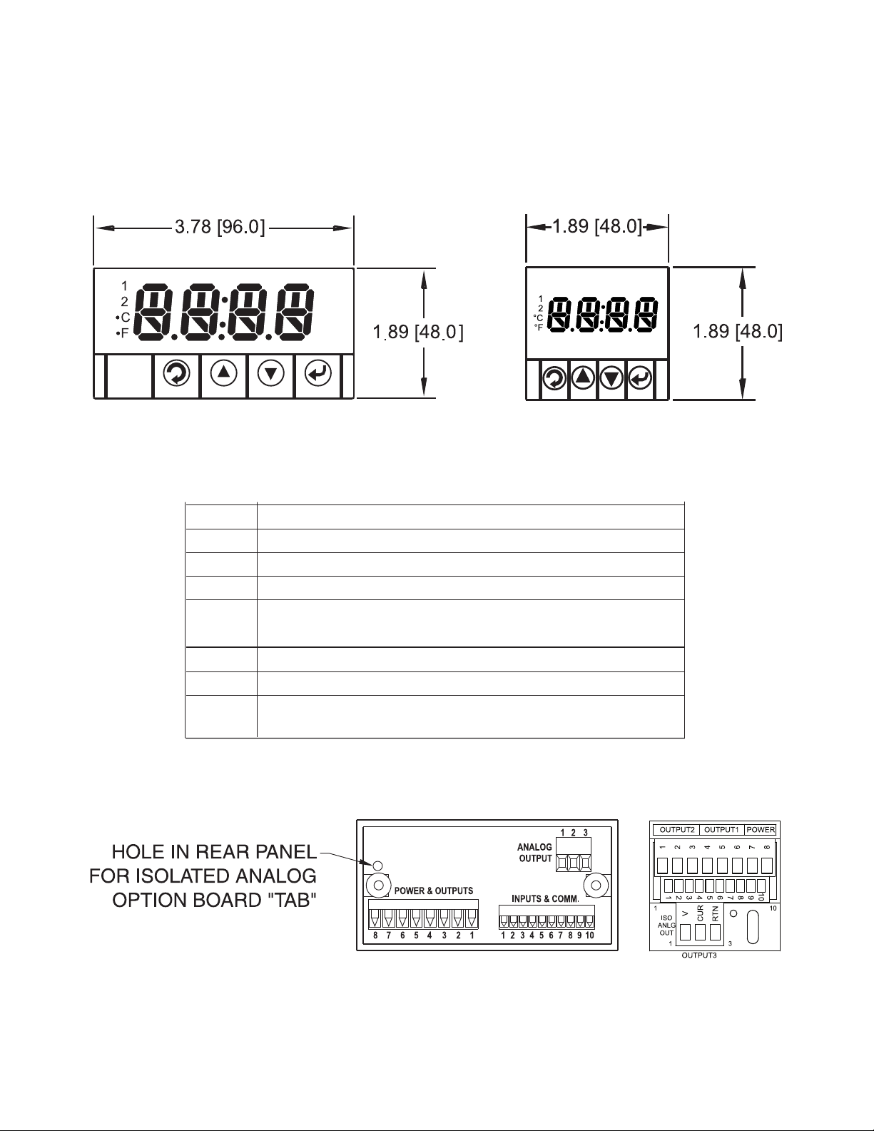
Figure 2.1
1
⁄8
and
1
⁄16
DIN Front Panel Display
Table 2.1 Front Panel Annunciators
1 Output 1/Setpoint 1/ Alarm 1 indicator
2 Setpoint 2/ Alarm 2 indicator
°C °C unit indicator
°F °F unit indicator
a
Changes display to Configuration Mode and
advances through menu items*
b
Used in Program Mode and Peak Recall*
c
Used in Program Mode and Valley Recall*
d
Accesses submenus in Configuration Mode
and stores selected values*
* See Part 3 Operation: Configuration Mode
Figure 2.2
1
⁄8
and
1
⁄16
DIN Rear View
5
Page 10
2.2
1
⁄8
DIN Rear Panel Connections
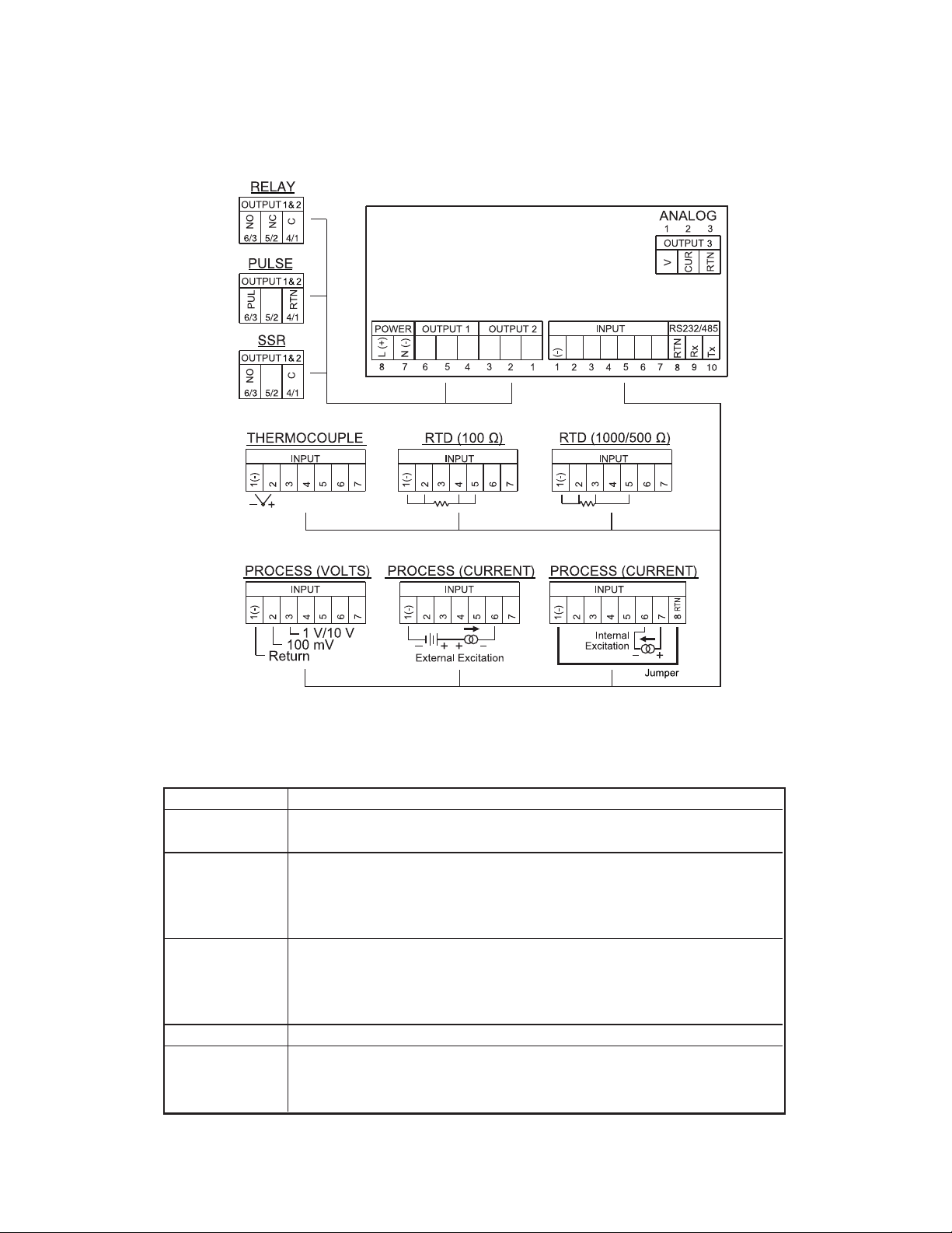
The rear panel connections are shown in Figure 2.3.
Figure 2.3
1
⁄8
DIN Rear Panel Input Connections
Table 2.2
1
⁄8
DIN Rear Panel Connector
POWER AC/DC Power Connector: All models
INPUT
Input Connector: All models TC, PR (Process), RTD
OUTPUT 1 Based on one of the following models:
Relay SPDT
Solid State Relay
Pulse
OUTPUT 2 Based on one of the following models:
(Alarm 2) Relay SPDT
Solid State Relay
Pulse
OUTPUT 3 Isolated Analog (Output Voltage and Current)
OPTION
Based on one of the following models:
RS232C or RS485 programmable
Excitation
6
Page 11
2.3
1
⁄16
DIN Rear Panel Connections
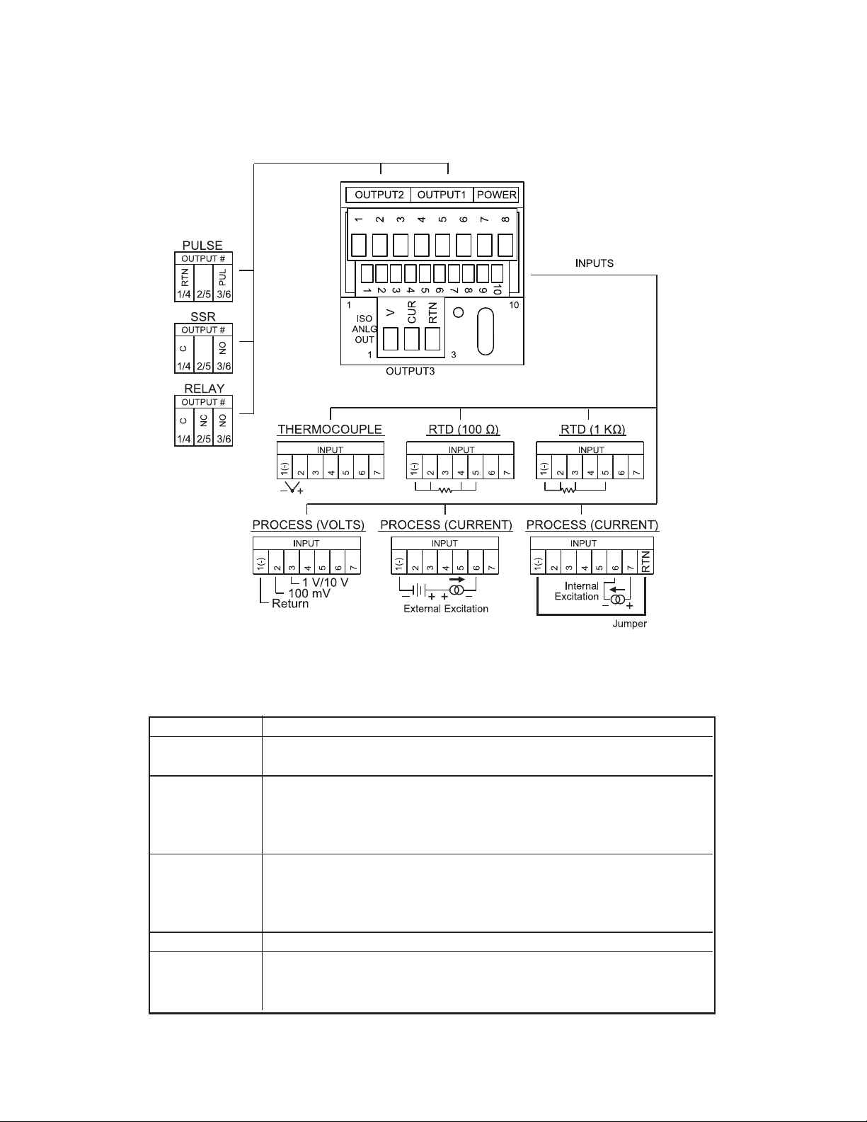
The rear panel connections are shown in Figure 2.3.
Figure 2.4
1
⁄16
DIN Rear Panel Input Connections
Table 2.3
1
⁄16
DIN Rear Panel Connector
POWER AC/DC Power Connector: All models
INPUT
Input Connector: All models TC, PR (Process), RTD
OUTPUT 1 Based on one of the following models:
Relay SPDT
Solid State Relay
Pulse
OUTPUT 2 Based on one of the following models:
(Alarm 2) Relay SPDT
Solid State Relay
Pulse
OUTPUT 3 Isolated Analog (Output Voltage and Current)
OPTION
Based on one of the following models:
RS232C or RS485 programmable
Excitation
7
Page 12
8
2.4 Electrical Installation
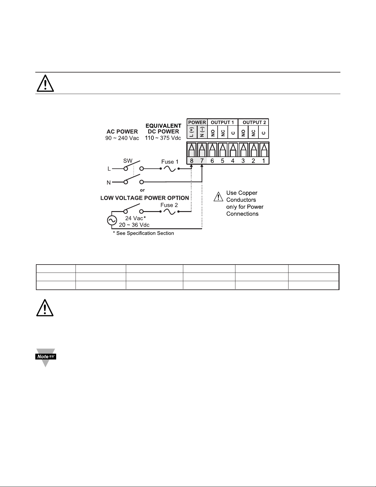
2.4.1 Power Connections
Caution: Do not connect power to your device until you have completed all
input and output connections. Failure to do so may result in injury!
Connect the main power connections as shown in Figure 2.4.
Figure 2.5 Main Power Connections
Table 2.4 Fuse Requirement (see Specifications)
FUSE Connector Output Type For 115Vac For 230Vac DC
FUSE 1 Power N/A 100 mA(T) 63 mA(T) 63 mA(T)
FUSE 2 Power N/A N/A N/A 400 mA(T)
For the low voltage power option, in order to maintain the same degree of
protection as the standard high voltage input power units (90 - 240 Vac),
always use a Safety Agency Approved DC or AC source with the same
Overvoltage Category and pollution degree as the standard AC unit
(90 - 240 Vac).
The Safety European Standard EN61010-1 for measurement, control,
and laboratory equipment requires that fuses must be specified based on
IEC127. This standard specifies for a Time-lag fuse, the letter code “T”.
The above recommended fuses are of the type IEC127-2-sheet III. Be
aware that there are significant differences between the requirements
listed in the UL 248-14/CSA 248.14 and the IEC 127 fuse standards. As a
result, no single fuse can carry all approval listings. A 1.0 Amp IEC fuse
is approximately equivalent to a 1.4 Amp UL/CSA fuse. It is advised to
consult the manufacturer’s data sheets for a cross-reference.
Page 13
9
2.4.2 Thermocouple
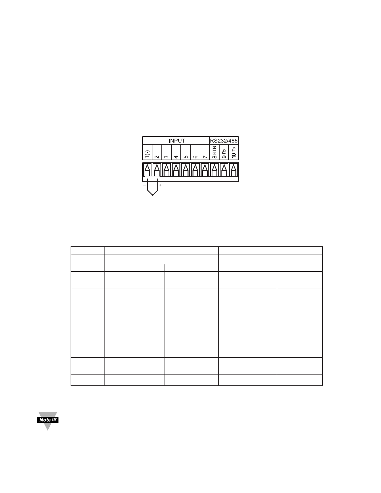
The figure below shows the wiring hookup for any thermocouple type. For
example, for Type K hookup, connect the yellow wire to the "2" terminal and the
red wire to the "1(-)" terminal.
When configuring your controller, select Thermocouple and Thermocouple
Type in the Input Type menu (see Part 3).
Figure 2.6 Thermocouple Wiring Hookup
If the input wires of the meter get disconnected or broken, it will display
+OPN “Input (+) Open” message. For safety purpose you may want to set
up your alarm to be triggered when input is open. Be sure to set your
Alarm correctly (see Alarm 1 & 2 chapters for details).
TYPE Input Connector Jacket (external insulation)
Terminal 1 (-) Terminal 2 (+) Extension Grade
J Red White dark-Brown Black
K Red Yellow dark-Brown Yellow
T Red Blue dark-Brown Blue
E Red Purple dark-Brown Purple
N Red Orange dark-Brown Brown
R Red Black - Green
S Red Black - Green
B Red Gray - Black
Table 2.5 TC Wire Color Chart
Page 14
10
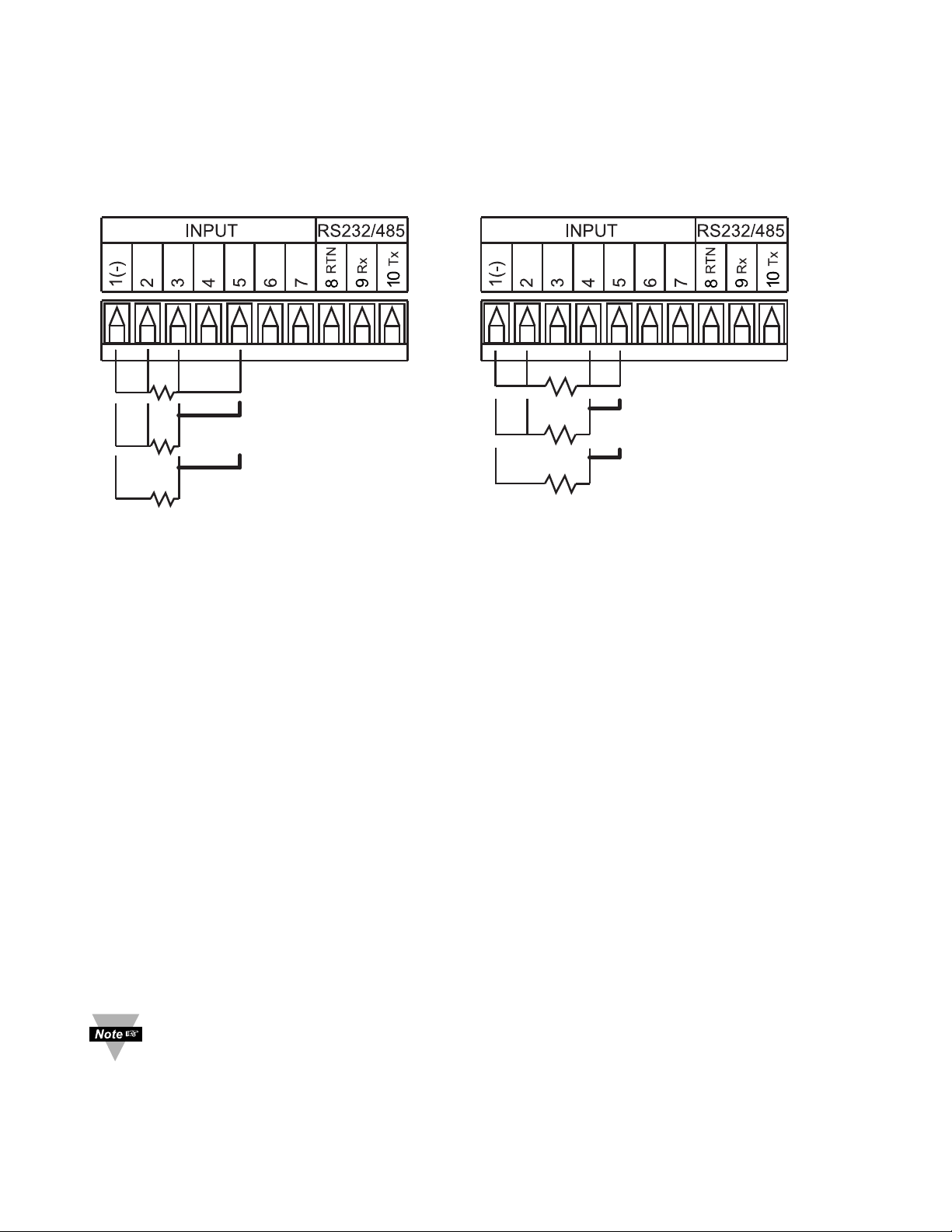
2.4.3 Two/Three/Four-Wire RTD
The figures below show the input connections and input connector jumpers
(shown in bold lines) required to hookup a 2-, 3- or 4-wire RTD.
Figure 2.7 a) RTD-1000 ohm and b) RTD-100 ohm Wiring Hookup
500 ohm Wiring Hookup
The two-wire connection is simplest method, but does not compensate for
lead-wire temperature change and often requires calibration to cancel lead-wire
resistance offset.
The three-wire connection works best with RTD leads closely equal in
resistance. The controller measures the RTD, plus upper and lower lead drop
voltage and the subtracts twice the measured drop in the lower supply current
lead producing excellent lead-resistance cancellation for balanced
measurements.
The four-wire RTD hookup is applicable to unbalanced lead resistance and
enables the device to measure and subtract the lead voltage, which produces
the best lead-resistance cancellation.
When configuring your controller, select RTD type and RTD value in the
Input Type menu (see Part 3).
If the input wires of the meter get disconnected or broken, it will display
+OPN “Input (+) Open” message except in case of 500/1000 Ω 2-wire
RTD. In this case the display shows -OPN “Input (-) Open” message. For
safety purpose you may want to set up your alarm to be triggered when
input is open. Be sure to set your Alarm correctly (see Alarm 1 & 2
chapters for details).
RTD (1000/5001) 4-Wire
RTD (1000/5001) 3-Wire
RTD (1000/5001) 2-Wire
RTD (1001) 4-Wire
RTD (1001) 3-Wire
RTD (1001) 2-Wire
Page 15
11
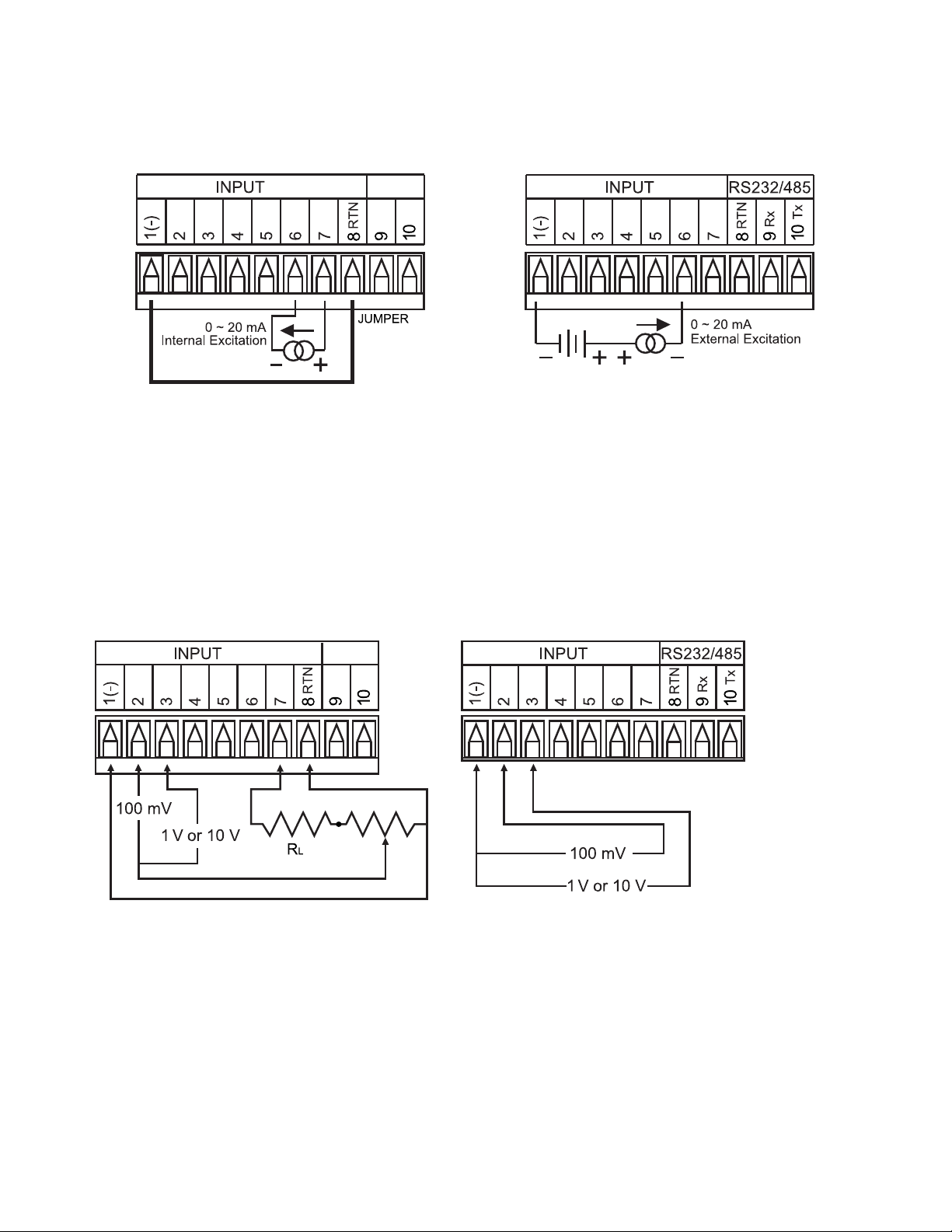
2.4.4 Process Current
The figure below shows the wiring hookup for Process Current 0 – 20 mA.
Figure 2.8 Process Current Wiring Hookup
(Internal and External Excitation)
When configuring your instrument, select Process Type in the Input Type
Menu (see Part 3).
2.4.5 Process Voltage
The figure below shows the wiring hookup for Process Voltage 0 – 100 mV,
0 – 1 V, 0 – 10 V.
Figure 2.9
a) Process Voltage Wiring Hookup b) Process Voltage Wiring Hookup
with Sensor Excitation without Sensor Excitation
RL - Voltage limited resistor, which allows to convert 24 Vdc internal excitation
voltage to the appropriate process input value. For instance: if the potentiometer
value is equal to 10 kΩ, the minimum RL is 14 kΩ for 10 V process input.
When configuring your instrument, select Process Type in the Input Type
Menu (see Part 3).
Page 16
12
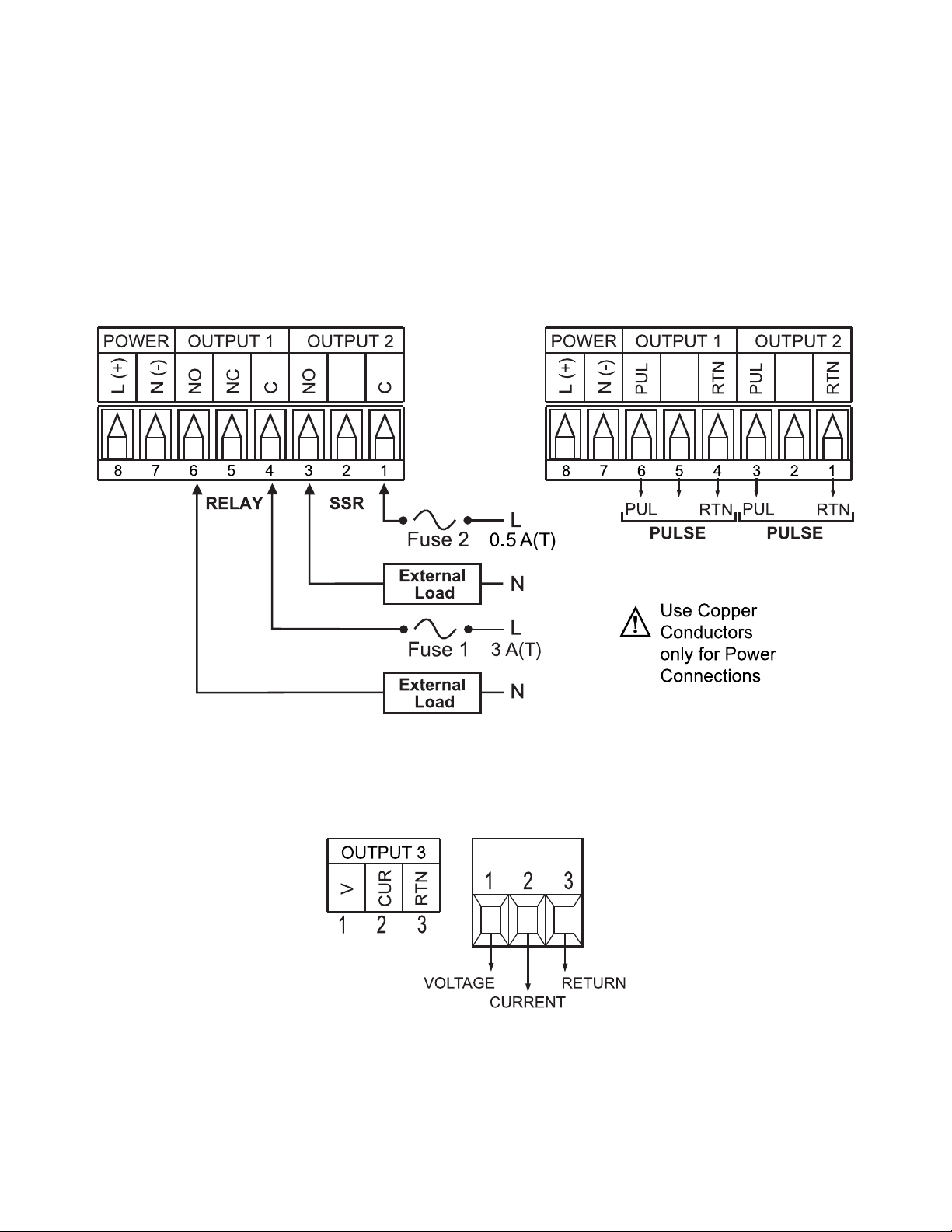
2.4.6 Wiring Outputs
Th
is meter has three factory installed outputs.
The Output 1 can be configured as Control Output or Alarm Output with SPDT
Mechanical Relay, SPST Solid State Relay or Pulse.
The Output 2 is Alarm Output with SPDT (Mechanical Relay, SPST Solid State
Relay or Pulse.
The Output 3 is Isolated Analog Output (retransmission) Voltage and Current
Output connnections are shown below.
Figure 2.10
a) Mechanical Relay and SSR b) Pulse Outputs Wiring
Outputs Wiring Hookup Hookup
Figure 2.11 Analog Output Wiring Hookup
Page 17
13
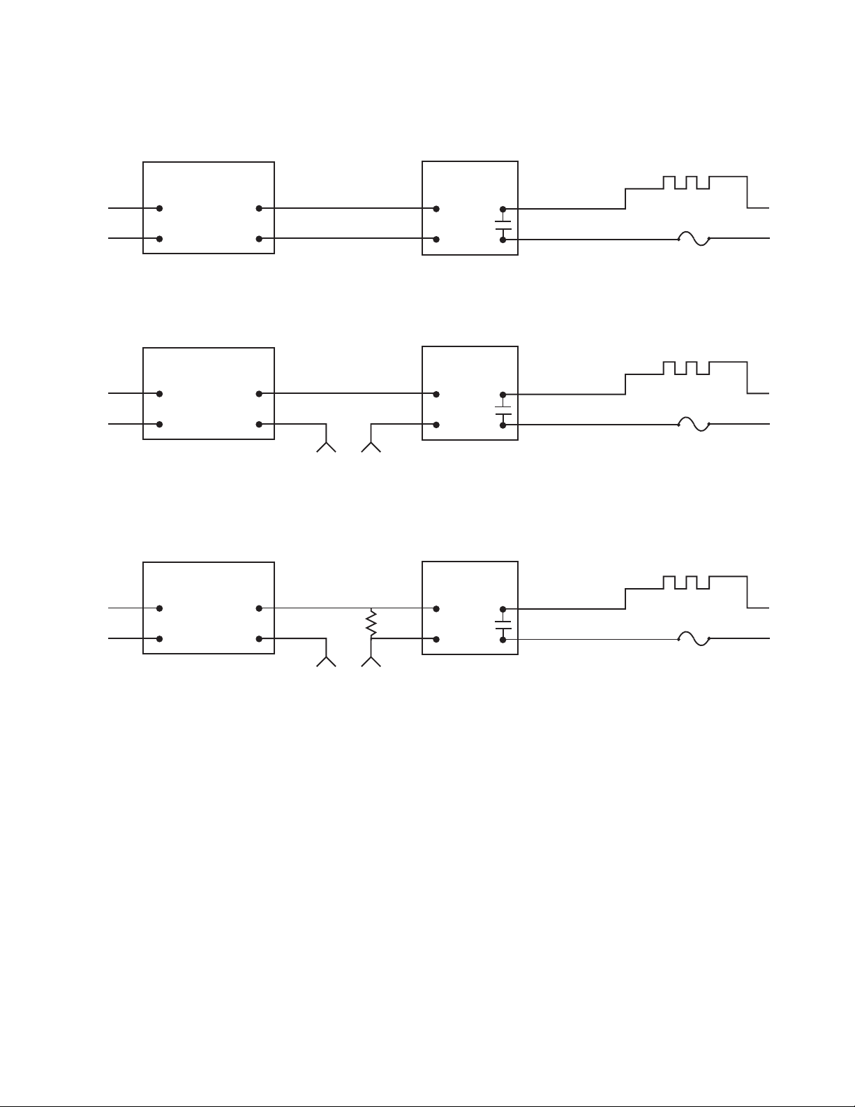
2.4.6 Wiring Outputs (continued)
Figure 2.12 Typical Applications
TEMPERATURE
CONTROLLER
CONTROL
SIDE
dc INPUT
SSR
ac INPUT
SSR
ac INPUT
SSR
LOAD
SIDE
HEATER
Vac
Vac
dc CONTROLLED SSR USED WITH TEMPERATURE CONTROLLER WITH dc VOLTAGE SSR DRIVER OUTPUT
FAST BLOW
FUSE
0 or 5 Vdc,
TYPICALLY
4
3
1
2
TEMPERATURE
CONTROLLER
CONTROL
SIDE
LOAD
SIDE
HEATER
Vac
Vac
ac CONTROLLED SSR USED WITH TEMPERATURE CONTROLLER WITH MECHANICAL RELAY OUTPUT
FAST BLOW
FUSE
Vac
DRIVING
SSR
4
3
1
2
TEMPERATURE
CONTROLLER
CONTROL SIDE
LOAD
RESISTOR
LOAD
SIDE
HEATER
Vac
Vac
ac CONTROLLED SSR USED WITH TEMPERATURE CONTROLLER WITH TRIAC OUTPUT
FAST BLOW
FUSE
Vac
DRIVING
SSR
4
3
1
2
Page 18
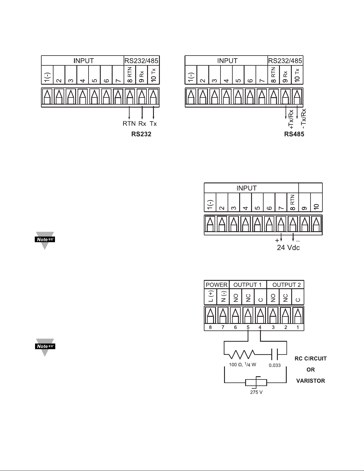
This device may also have a programmable communication output. The RS232
and RS485 Output Connection are shown below.
Figure 2.13
a) RS232 Output Wiring Hookup b) RS485 Output Wiring Hookup
This meter is capable of supplying 24 Vdc
sensor excitation. The excitation output
connection is shown below. This option is not
available for low voltage power supply.
I
f your meter has an excitation option,
then communication is not available.
Figure 2.14 Excitation Output
This meter has snubber circuits
designed to protect the contacts of
the mechanical relays when it
switches inductive loads (i.e.
solenoids, relays). These snubbers
are internally connected between the
Common (C) and Normally Open
(NO) relay contacts of Output 1 and
Output 2.
If you have an inductive load
connected between Common (C) and
Normally Closed (NC) contacts of the
mechanical relays and you want to
protect them from the rush current
during the switching period, you have
to connect an external snubber circuit
between Common (C) and
Normally Closed (NC) contacts as
indicated in the figure below.
14
Figure 2.15
Snubber Circuits Wiring Hookup
Page 19
15
PART 3
OPERATION: Configuration Mode
3.1 Introduction
The instrument has two different modes of operation. The first, Run Mode, is
used to display values for the Process Variable, and to display or clear Peak
and Valley values. The other mode, Menu Configuration Mode, is used to
navigate through the menu options and configure the controller. Part 3 of this
manual will explain the Menu Configuration Mode. For your instrument to
operate properly, the user must first "program" or configure the menu options.
Turning your Contro ller On for the Firs t Time
The device becomes active as soon as it is connected to a power source. It
has no On or Off switch. The device at first momentarily shows the software
version number, followed by reset
RST
, and then proceeds to the Run Mode
For first-time users: Refer to the QuickStart Manual for basic operation
and set-up instructions.
If you have the Serial Communications Option you can easily configure
the controller on your computer.
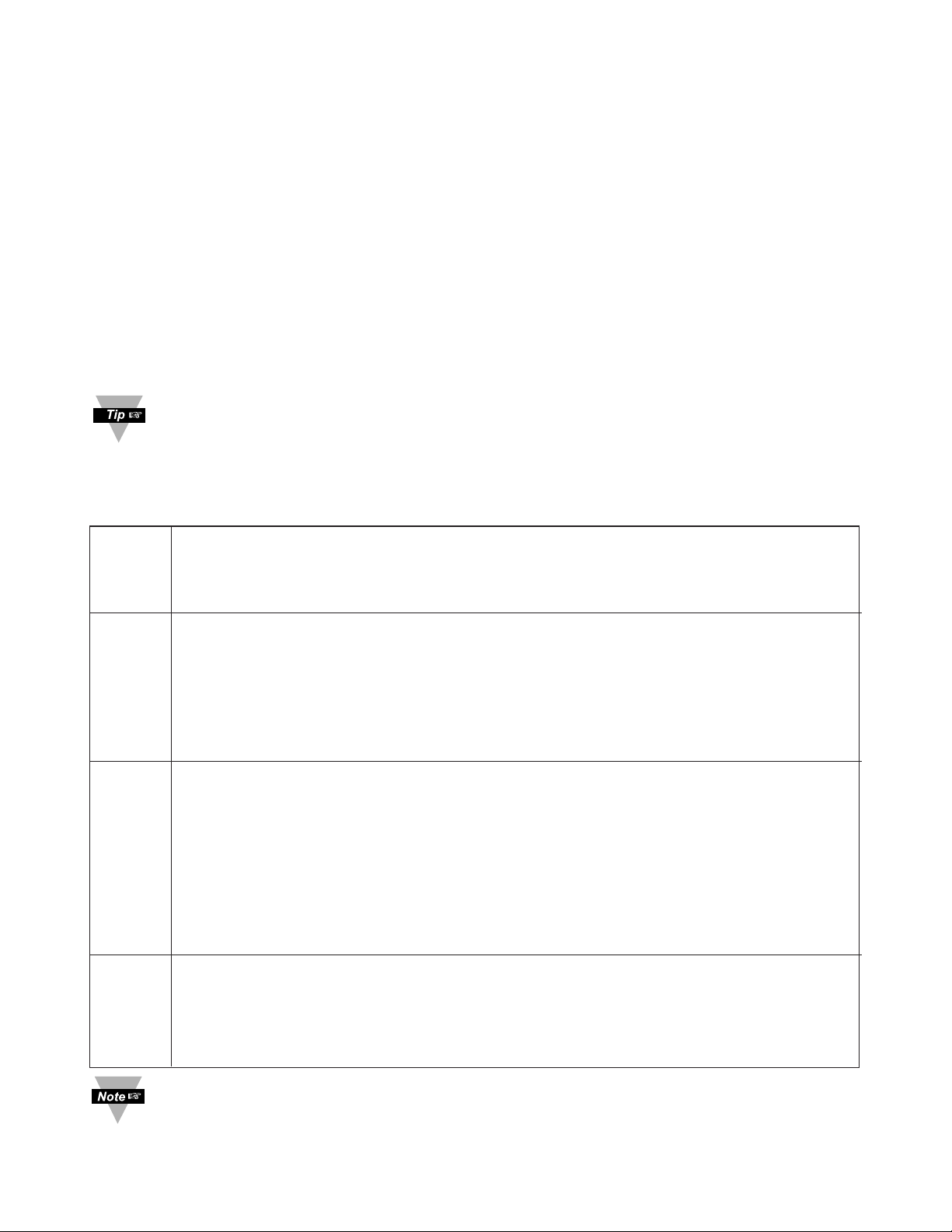
Table 3.1 Bu tton Fu nction in Configurat ion Mod e
•To enter the Menu, the user must first press abutton.
•Use this button to advance/navigate to the next menu item. The user can
navigate through all the top level menus by pressing a.
•While a parameter is being modified, press ato escape without saving the parameter.
•Press the up bbutton to scroll through “flashing” selections. When a numerical
value is displayed press this key to increase value of a parameter that is
currently being modified.
•Holding the bbutton down for approximately 3 seconds will speed up the rate at
which the set point value increments.
•In the Run Mode press bcauses the display to flash the PEAK value – press
again to return to the Run Mode.
•Press the down cbutton to go back to a previous Top Level Menu item.
•Press this button twice to reset the controller to the Run Mode.
•When a numerical value is flashing (except set point value) press cto scroll
digits from left to right allowing the user to select the desired digit to modify.
•When a setpoint value is displayed press cto decrease value of a setpoint that
is currently being modified. Holding the cbutton down for approximately 3
seconds will speed up the rate at which the setpoint value is decremented.
•In the Run Mode press c causes the display to flash the VALLEY value – press
again to return to the Run Mode.
•Press the enter d button to access the submenus from a Top Level Menu item.
•Press d to store a submenu selection or after entering a value — the display will
flash a
STRD
message to confirm your selection.
•To reset flashing Peak or Valley press d.
•In the Run Mode, press d twice to enable Standby Mode with flashing
STBY
.
Reset: Except for Alarms, modifying any settings of the menu configuration
will reset the instrument prior to resuming Run Mode.
a
MENU
b
(UP)
c
(DOWN)
d
ENTER
Page 20
16
3.2 Menu Configuration
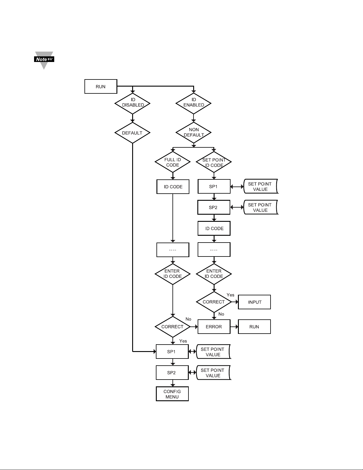
It is required that you put the controller in the Standby Mode for any
configuration change other than Setpoints & Alarms.
Figure 3.1 Flow Chart for ID and Set Points
Page 21
17
3.2.1 ID Number
SEE ID MENU SELECTION IN CONFIGURATION SECTION FOR
ENABLE/DISABLE OR CHANGE ID CODE.
If ID Code is Disabled or set as Default (0000) the menu will skip ID step
to Set Point Menu.
If ID Code is set to Full Security Level and user attempts to enter the
Main Menu, they will be prompted for an ID Code.
If ID Code is set to Setpoint/ID Security Level and user attempts to enter
the Configuration Menu, they will be prompted for an ID Code.
ENTERING YOUR NON-DEFAULT FULL SECURITY ID NUMBER.
Press a 1) Display shows ID.
Press d 2) Display advances to
____
.
Press b & c 3) Press bto increase digit 0-9. Press cto activate next digit
(flashing).
Continue to use band c to enter your 4-digit ID code.
Press d 4) If the correct ID code is entered, the menu will advance to the
Setpoint 1 Menu, otherwise an error message
ERRo
will be
displayed and the instrument will return to the Run Mode.
To change ID Code, see ID Menu in the Configuration section.
ENTERING YOUR NON-DEFAULT SETPOINT/ID SECURITY ID NUMBER.
Press a 5) Display shows
SP1
Setpoint 1 Menu.
Press a 6) Display shows
SP2
Setpoint 2 Menu.
Press a 7) Display shows
ID
ID Code Menu.
Press d 8) Display advances to
____
.
Press b & c 9) Use b and c to change your ID Code.
Press d 10) If correct ID Code is entered, the display will advance to the
INPT
Input Menu, otherwise the error message
ERRo
will be
displayed and the controller will return to the Run Mode.
To prevent unauthorized tampering with the setup parameters, the
controller provides protection by requiring the user to enter the ID Code
before allowing access to subsequent menus. If the ID Code entered
does not match the ID Code stored, the controller responds with an error
message and access to subsequent menus will be denied.
Use numbers that are easy for you to remember. If the ID Code is
forgotten or lost, call customer service with your serial number to access
and reset the default to
0000
.
Page 22
18
3.2.2 Set Points
SETPOINT 1:
Press a 1) Press a, if necessary until
SP1
prompt appears.
Press d 2) Display shows previous value of “Setpoint 1” with 1
st
digit
flashing.
Press b & c 3) Press b and c to increase or decrease Setpoint 1
respectively.
Holding b & c buttons down for approximately 3 seconds will speed up the
rate at which the set point value increments or decrements.
Press b & c 4) Continue to use b and c to enter your 4-digit Setpoint 1 value.
Press d 5) Display shows
STRD
stored message momentarily and then
advance to
SP2
only, if a change was made, otherwise press a
to advance to
SP2
Setpoint 2 Menu.
SETPOINT 2:
Press d 6) Display shows previous value of “Setpoint 2” with 1
st
digit
flashing.
Press b & c 7) Press b and c to increase or decrease Setpoint 2
respectively.
Holding b & c buttons down for approximately 3 seconds will speed up
the rate at which the setpoint value increments or decrements.
Press d 8) Display shows
STRD
stored message momentarily and then
advances to
CNFG
only, if a change was made,
otherwise press
a to advance to
CNFG
Configuration Menu.
Page 23
19
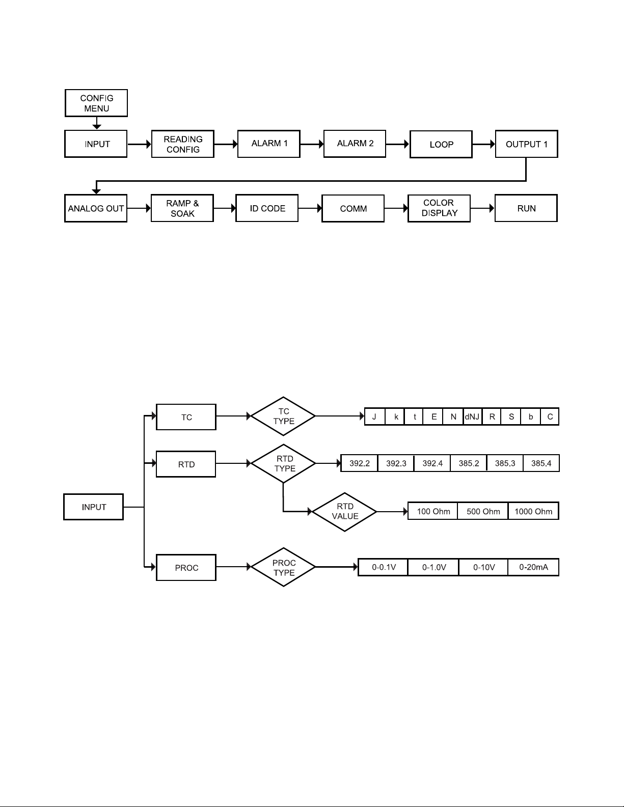
3.2.3 Configuration Menu
Figure 3.2 Flow Chart for Configuration Menu
Enter Configuration Menu:
Press a 1) Press a, if necessary, until
CNFG
prompt appear.
Press d 2) Display advance to
INPT
Input Menu.
Press a 3) Pressing and releasing a to scroll through all available
menus of Configuration section.
3.2.4 Input Type Menu
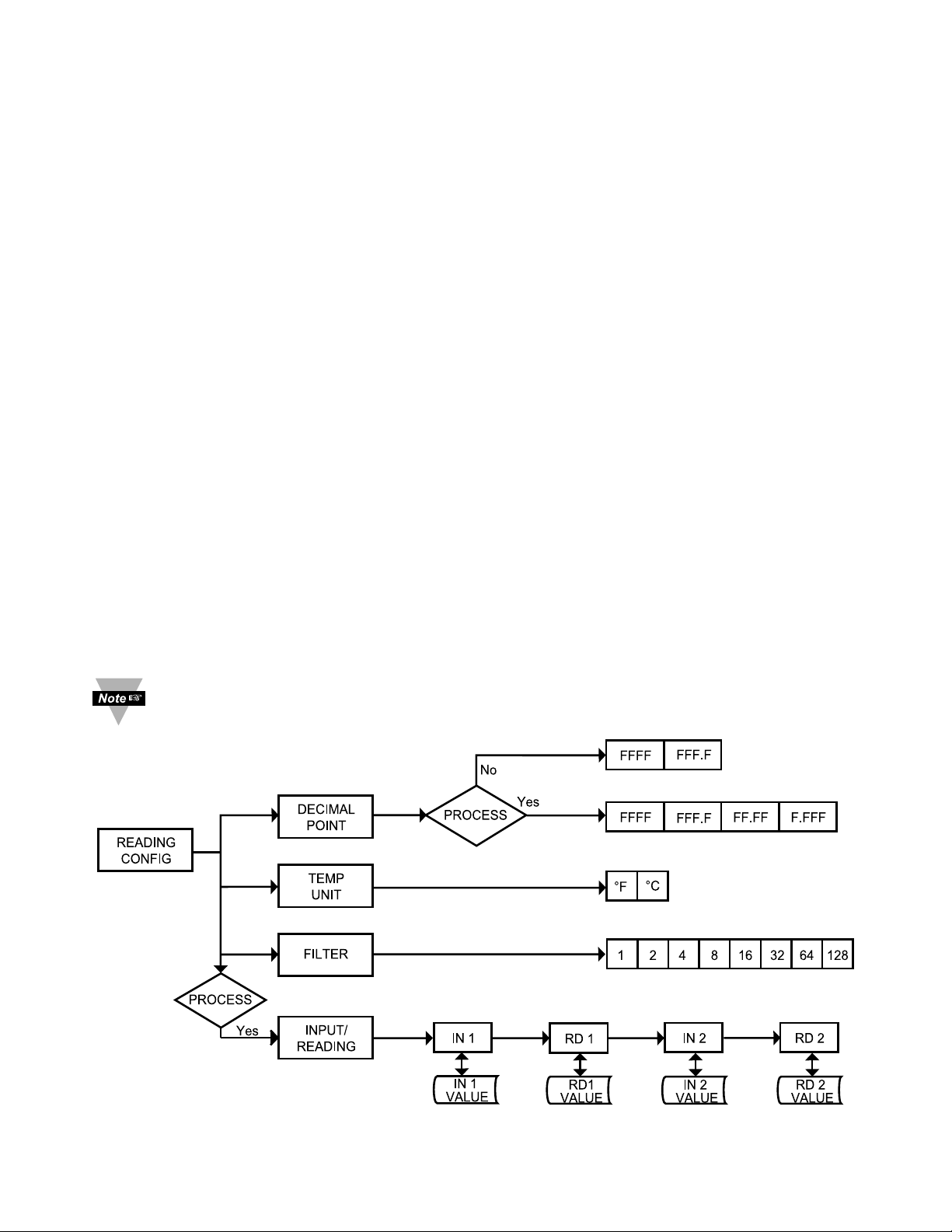
Figure 3.3 Flow Chart for Input Type Menu
Page 24

20
Input Type (Thermocouple)
ENTER INPUT TYPE MENU:
Press a 1) Press a, if necessary, until
CNFG
prompt appears.
Press d 2) Display advance to
INPT
Input Menu.
Press d 3) Display flashes
T.ç, RTD
or
PROC
(Thermocouple, RTD or
Process). If the displayed input type is
T.ç
, press a to skip to
step 6 (
T.ç
stops flashing).
THERMOCOUPLE SUBMENU:
Press b 4) Scroll through the available selection to
T.ç
(flashing).
Press d 5) Display shows
STRD
stored message momentarily and then
T.ç
(not flashing).
Press d 6) Display flashes previous thermocouple type selection. i.e.
J
(see below for types).
Press b 7) Scroll through the available thermocouple types to the
selection of your choice.
Press d 8) Display shows
STRD
stored message momentarily and then
advances to the
RDG
Reading Configuration Menu.
Use the Input Type (Thermocouple) (RTD) or (Process) and verify your
Electrical Installation (see Section 2.3). See the following pages for (TC),
(RTD), (Process) menus.
Thermocouple Types: J, K, T, E, N, DIN J, R, S, B, C
Display:
JKTEN DNJ RSBC
Page 25

21
Input Type (RTD)
ENTER INPUT TYPE MENU:
Press a 1) Press a, if necessary, until
CNFG
prompt appears.
Press d 2) Display advances to
INPT
Input Menu.
Press d 3) Display flashes
T.ç
,
RTD
or
PROC
(Thermocouple, RTD or
Process). If the displayed input type is
RTD
, press a to skip to
step 6 (
RTD
stops flashing).
RTD SUBMENU:
Press b 4) Scroll through the available selection to
RTD
(flashing).
Press d 5) Display shows
STRD
stored message momentarily and then
RTD
(not flashing).
Press d 6) Display flashes previous RTD type selection i.e.
392.2
(see below for RTD types selection).
Press b 7) Scroll through the available RTD types to the selection of
your choice.
Press d 8) Display shows
STRD
stored message momentarily and then
advances to
RTD
RTD value.
RTD Types: 392 385 Two, Three or Four-wire
Display:
392.2,392.3,392.4,385.2,385.3,385.4
Last digit indicates: 2-, 3- or 4-wire input.
RTD VALUE SUBMENU:
Press d 9) Display flashes previous RTD value selection i.e.
100_
(see below for RTD value selection).
Press b 10) Scroll through the available RTD values to the selection of
your choice.
Press d 11) Display shows
STRD
stored message momentarily and then
advances to
RDG
Reading Configuration Menu.
RTD Values: 100 ohm 500 ohm 1000 ohm
Display:
100_ 500_ 1000
Page 26
22
Input Type (Process)
ENTER INPUT TYPE MENU:
Press a 1) Press a, if necessary, until
CNFG
prompt appears.
Press d 2) Display advance to
INPT
Input Menu.
Press d 3) Display flashes
T.ç, RTD
or
PROC
(Thermocouple, RTD or
Process). If the displayed input type is
PROC
, press a to skip to
step 6 (
PROC
stops flashing).
PROCESS SUBMENU:
Press b 4) Scroll through the available selection to
PROC
(flashing).
Press d 5) Display shows
STRD
stored message momentarily and then
PROC
(not flashing).
Press d 6) Display flashes previous Process type selection. i.e.
0-10
(see below for Process types selection).
Press b 7) Scroll through the available Process types to the selection of
your choice.
Press d 8) Display shows
STRD
stored message and then advances to
RDG
Reading Configuration Menu.
Process Types: 100 mV 1 V 10 V 0 – 20 mA
Display:
0-0.1 0-1.0 0-10 0-20
For 4-20 mA Input select 0-20 mA and adjust the Input/Reading accordingly.
To adjust 4-20 mA input, see example under Input/Reading Submenu.
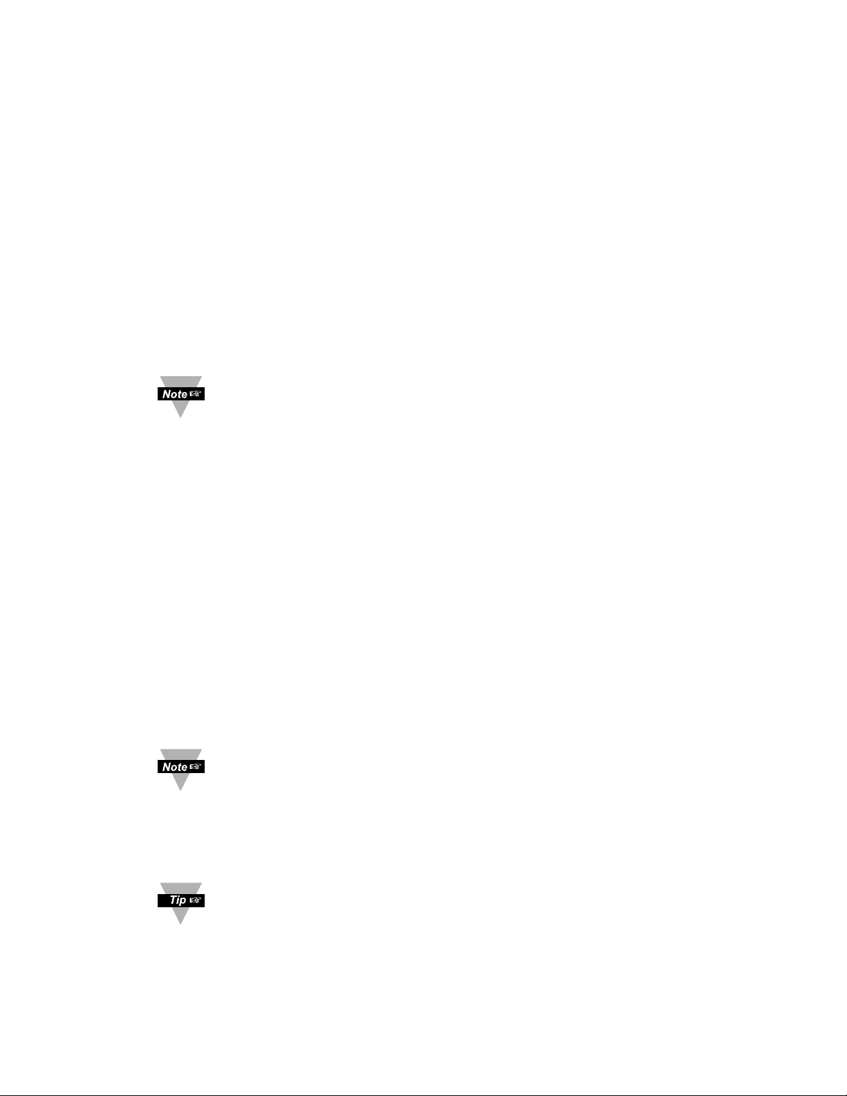
3.2.5 Reading Configuration Menu
Figure 3.4 Flow Chart for Reading Configuration Menu
It is required that you put the controller in the Standby Mode for any
configuration change other than Set Points & Alarms.
Page 27
23
ENTER READING CONFIGURATION MENU:
Press
a
1) Press a, if necessary, until
CNFG
prompt appears.
Press
d
2) Display advances to
INPT
Input Menu.
Press
a
3) Display advances to
RDG
Reading Configuration Menu.
Press
d
4) Display advances to
DEC
Decimal Point.
DECIMAL POINT SUBMENU:
Press
d
5) Display flashes previous selection for Decimal location.
Press
b
6) Scroll though the available selections and choose Decimal
location:
FFFF
or
FFF.F
(also
FF.FF
and
F.FFF
— if
PROC
Process type was selected in the Input Type Menu).
Press
d
7) Display shows
STRD
stored message momentarily and then
advances to
TEMP
Temperature Unit.
Decimal Point for Process Input Type is passive.
TEMPERATURE UNIT SUBMENU:
Press
d
8) Display flashes previous Temperature Unit selection.
Press
b
9) Scroll though the available selections to the Temperature Unit
of your choice: °For °C.
Press
d
10) Display shows
STRD
stored message momentarily and then
advances to
FLTR
Filter Constant.
FILTER CONSTANT SUBMENU:
Press
d
11) Display flashes previous selection for Filter Constant.
Press
b
12) Scroll though the available selections:
0001,0002,0004
,
0008,0016,0032,0064,0128
. - Default is
0004
Press
d
13) Display shows
STRD
stored message momentarily only, if a
change was made, otherwise press ato advance to the next menu.
If Process was selected in the Input Type Menu the display will
advance to
IN.RD
Input/Reading Submenu, otherwise the
display advances to the
ALR1
Alarm 1 Menu.
The Filter Constant Submenu allows the user to specify the
number of readings stored in the Digital Averaging Filter.
For PID control select filter value 0001-0004. A filter value of 2 is
approximately equal to 1 second RC low pass time constant.
Page 28
24
Reading Configuration (If Process was selected)
INPUT/READING (SCALE AND OFFSET) SUBMENU:
Input Voltage or Current can be converted or scaled into values appropriate for
the process or signal being measured. So, a reading may be displayed, for
example, in units of weight or velocity instead of in amperes or volts.
The instrument determines Scale and Offset values based on two user-provided
input values entered with the corresponding readings. Note that “In1” Input 1 and
“In2” Input 2 are represented and entered as a product of the input
voltage/current and the conversion number from the Table 3.2.
The following instructions include details for a specific scenario in which a
4-20 mA input (in the 20 mA Process Mode) is to be represented as a
measurement of 0-100 percent.
Press
d
14) Press dat the
IN.RD
prompt. Display shows
IN1
Input 1
Submenu.
Press
d
15) Display shows Input 1 value with 1
st
digit flashing.
Press b&
c
16) Use band cbuttons to enter
IN1
value.
The
IN1
value = min. input value * conversion number.
Disregard the position of the decimal point (2000 counts may
actually appear as “2000”, “200.0”, “20.00”, or “2.000”).
Example: 4 mA as 4(mA) x 500 = 2000.
Press
d
17) Display advances to
RD1
Reading 1 Submenu.
Press b&
c
18) Use band cbuttons to enter
RD1
value.
This value represents
IN1
in terms of some meaningful
engineering units. To show the 4 mA as zero percent enter
RD1
value = 0000.
Example
:
RD1
value = 0000.
Press
d
19) Display
IN2
Input 2 Submenu.
Press
d
20) Display shows Input 2 value with 1stdigit flashing.
The
IN2
value = max. input value * conversion number.
Example
: 20(mA) x 500 = 10000 (9999).
Press b&
c
21) Use band cbuttons to enter
IN2
value.
Press
d
22) Display advances to
RD2
Reading 2 Submenu.
Press b&
c
23) Use band cbuttons to enter
RD2
value.
Example
:
RD2
value = 0100.
Press
d
24) Display flashes
STRD
stored message momentarily and
then advances to
ALR1
only, if change was made, otherwise
press dto advance to
ALR1
Alarm 1 Menu.
Page 29
25
Conversion number is a coefficient of conversion between input values
and real full display range (10000 counts, shown as 9999). See Table 3.2
below for proper conversion number.
Table 3.2 Conversion Table
RANGE CONVERSION NUMBER
100 mV 10000 / (100 x 1) = 100
1 V 10000 / (1000 x 1) = 10
10 V 10000 / (1000 x 10) = 1
0 -20 mA 10000 / (20 x 1) = 500
Example =
0 - 1 V = 0 - 100.0
In 1 = 0
Rd 1 = 0
Inp 2 = 9999
Rd 2 = 100.0
Page 30
26
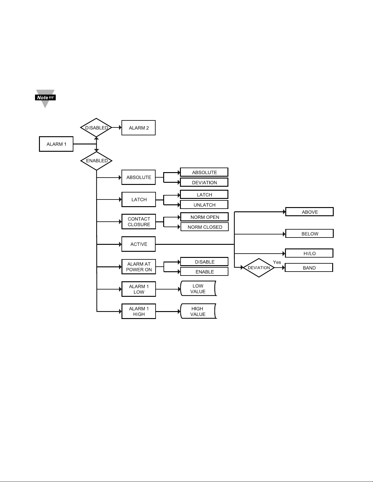
3.2.6 Alarm 1
This unit is equipped with three physical outputs that can only be configured as
follows:
a) Alarm 1, Alarm 2 & Analog Output
b) Output 1, Alarm 2 & Analog Output
Alarm must be DISABLED if Ramp is ENABLED.
Figure 3.5 Flow Chart for Alarm 1
ENTER ALARM 1 MENU:
Press a 1) Press a, if necessary, until
CNFG
prompt appears.
Press d 2) Display advances to
INPT
Input Menu.
Press a 3) Press a, if necessary, until Display advances to
ALR1
Alarm 1
Menu.
Press d 4) Display advances to Alarm 1
ENBL
Enable or
DSBL
Disable
Submenu and flashes the previous selection.
Page 31

27
ALARM 1 ENABLE/DISABLE SUBMENU:
Press b 5) Scroll though the available selection until
ENBL
displays to
use Alarm 1.
Press d 6) Display shows
STRD
stored message momentarily and then
advances to
ABSo
only, if it was changed, otherwise press a to
advance to
ABSo
Alarm 1 Absolute/Deviation Submenu.
If
DSBL
Alarm 1 Disabled was selected, all submenus of Alarm
1 Menu will be skipped and meter advances to
ALR2
Alarm 2
Menu. If
ENBL
Alarm 1 Enabled was selected, Output 1 would
be automatically disabled, and reassigned as Alarm 1.
ALARM 1 ABSOLUTE/DEVIATION SUBMENU:
Press
d
7) Display flashes previous selection. Press bto
ABSo
Absolute or
_DEV
Deviation.
Press
d
8) Display shows
STRD
stored message momentarily and then
advances to
LTçH
only, if it was changed, otherwise press a to
advance to
LTçH
Alarm 1 Latch/Unlatch Submenu.
Absolute Mode allows Alarm 1 to function independently from Setpoint 1. If the
process being monitored does not change often, then "Absolute" Mode is
recommended.
Deviation Mode allows changes to Setpoint 1 to be made automatically to
Alarm 1. Deviation Mode is typically the ideal mode if the process temperature
changes often. In Deviation Mode, set Alarm 1 a certain number of degrees or
counts away from Setpoint 1 — this relation remains fixed even if Setpoint 1 is
changed.
ALARM 1 LATCH/UNLATCH SUBMENU:
Press
d
9) Display flashes previous selection. Press bto
LTçH
Latched
or
UNLT
Unlatched.
Press
d
10) Display shows
STRD
stored message momentarily and then
advances to
CT.CL
only, if it was changed, otherwise press a to
advance to
CT.CL
Contact Closure Submenu.
Latched Mode: Relay remains "latched" until reset. To reset already latched
alarm, select Alarm Latch and press Max twice (i.e. Unlatch and then back to
Latch) or from a Run Mode, push dtwice to put the controller in Standby Mode
and then push done more time to return to the Run Mode.
Unlatched Mode: Relay remains latched only as long as the alarm condition is
true.
Page 32

28
CONTACT CLOSURE SUBMENU:
Press
d
11) Display flashes previous selection. Press b to
N.ç
. Normally
Closed or
N.o.
Normally Open.
Press
d
12) Display shows
STRD
stored message momentarily and then
advances to
AçTV
only, if it was changed, otherwise press ato
advance to
AçTV
Active Submenu.
Normally Open: If this feature is selected, then the relay is "energized" only
when an alarm condition occurs.
Normally Closed: "Fail Safe" Mode. Relay is energized under "normal"
conditions and becomes de-energized during alarm or power failure.
ACTIVE SUBMENU:
Press
d
13) Display flashes previous selection. Press bto scroll through
the available selections:
ABoV
Above,
BELo
Below,
HI.Lo
HI/Low and
BAND
Band. (Band is active if
_DEV
Deviation was
selected).
Press
d
14) Display shows
STRD
stored message momentarily and then
advances to
A.P.oN
only, if it was changed, otherwise press a to
advance to
A.P.oN
Alarm Enable/Disable at Power On Submenu.
Above: Alarm 1 condition triggered when the process variable is greater than the
Alarm Hi Value (Low value ignored).
Below: Alarm 1 condition triggered when the process variable is less than the
Alarm Low Value (Hi value ignored).
Hi/Low: Alarm 1 condition triggered when the process variable is less than the
Alarm Low Value or above the Hi Value.
Band: Alarm 1 condition triggered when the process variable is above or below
the "band" set around Setpoint 1. Band equals Hi Value (Low Value ignored). A
"band" is set around the Setpoint by the instrument only in the "Deviation" Mode.
The Band for the AL 1 would be following the Setpoint 1 value
The Band for the AL 2 would be following the Setpoint 2 value.
The Band or the Deviation Value should be entered under:
AL1 High (if they want Alarm 1)
AL2 High (if they want Alarm 2)
AL Low value is ignored in the Band mode.
Example: if customer requires a Deviation Value of ±10 degrees around a
setpoint (using Output 2 as alarm)
Alarm 2: - Deviation
Contact Closure type: Deviation---Band
AL2 High: 10 (Band they want around Setpoint 2)
Then the Band Value is to be entered under AL2 HI: 10 not 80+10 = 90
Page 33

29
ALARM ENABLE/DISABLE AT POWER ON:
Press
d
15) Display flashes previous selection. Press bto
ENBL
enable
or
DSBL
disable.
Press d 16) Display shows
STRD
stored message. momentarily and
then advances to
ALR.L
only, if it was changed, otherwise press
a
to advance to the
ALR.L
Alarm 1 Low Value Submenu.
If the alarm is enabled at Power On, the alarm will be active right after
reset. If the alarm is disabled at Power On, the alarm will become
enabled when the process value enters the non alarm area. The alarm is
not active while the process value is approaching Setpoint 1.
ALARM 1 LOW VALUE SUBMENU:
Press
d
17) Display flashes 1
st
digit of previous value. Use band cto
enter new value.
Press b& c18) Use band cto enter Alarm 1 Low Value.
Press
d
19) Display shows
STRD
storage message momentarily and
then advances to
ALR.H
only, if it was changed, otherwise press
a to advance to
ALR.H
Alarm 1 Hi Value Submenu.
ALARM 1 HI VALUE SUBMENU:
Press
d
20) Display flashes 1stdigit of previous value. Use band cto
enter new value.
Press b& c21) Use band cto enter Alarm1 Hi Value.
Press
d
22) Display shows
STRD
stored message momentarily and then
advances to the next menu only, if it was changed, otherwise
press ato advance to the next menu.
Page 34
30
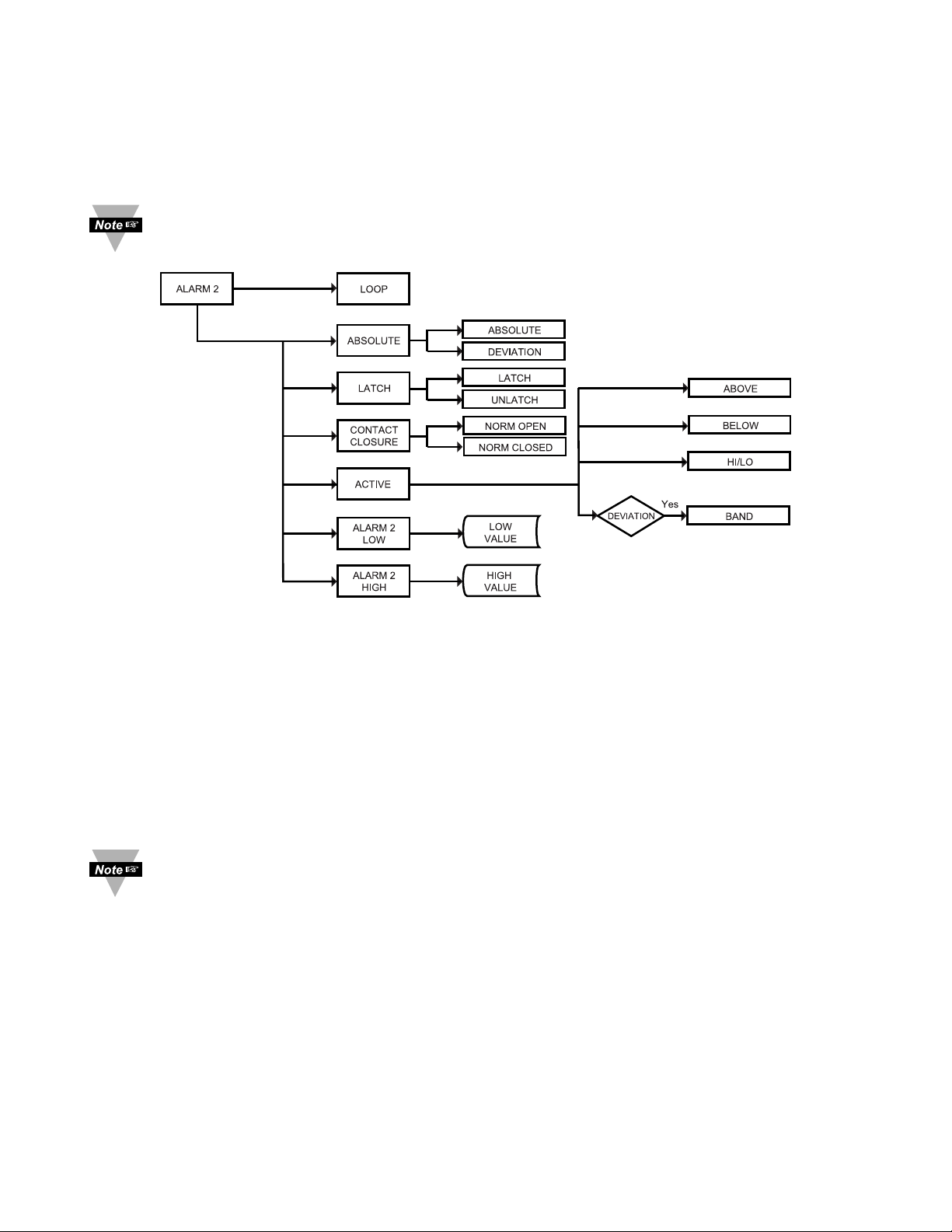
3.2.7 Alarm 2
This unit is equipped with three physical outputs that can only be configured as:
a) Alarm 1, Alarm 2 & Analog Output
b) Output 1, Alarm 2 & Analog Output
Alarm must be DISABLED if Ramp is ENABLED.
Figure 3.6 Flow Chart for Alarm 2
ENTER ALARM 2 MENU:
Press
a
1) Press a, if necessary, until
CNFG
prompt appears.
Press
d
2) Display advances to
INPT
Input Menu.
Press
a
3)
Press a, if necessary, until Display advances to
ALR2
Alarm 2
Menu.
Press
d
4) Display advances to
ABSo
Absolute/Deviation Submenu.
Alarm 2 menu items are identical to Alarm 1 Menu, except Alarm 2 does
not have Alarm enable/disable at Power On submenu item. Modifying
Alarm Settings will not reset the instrument.
Page 35
31
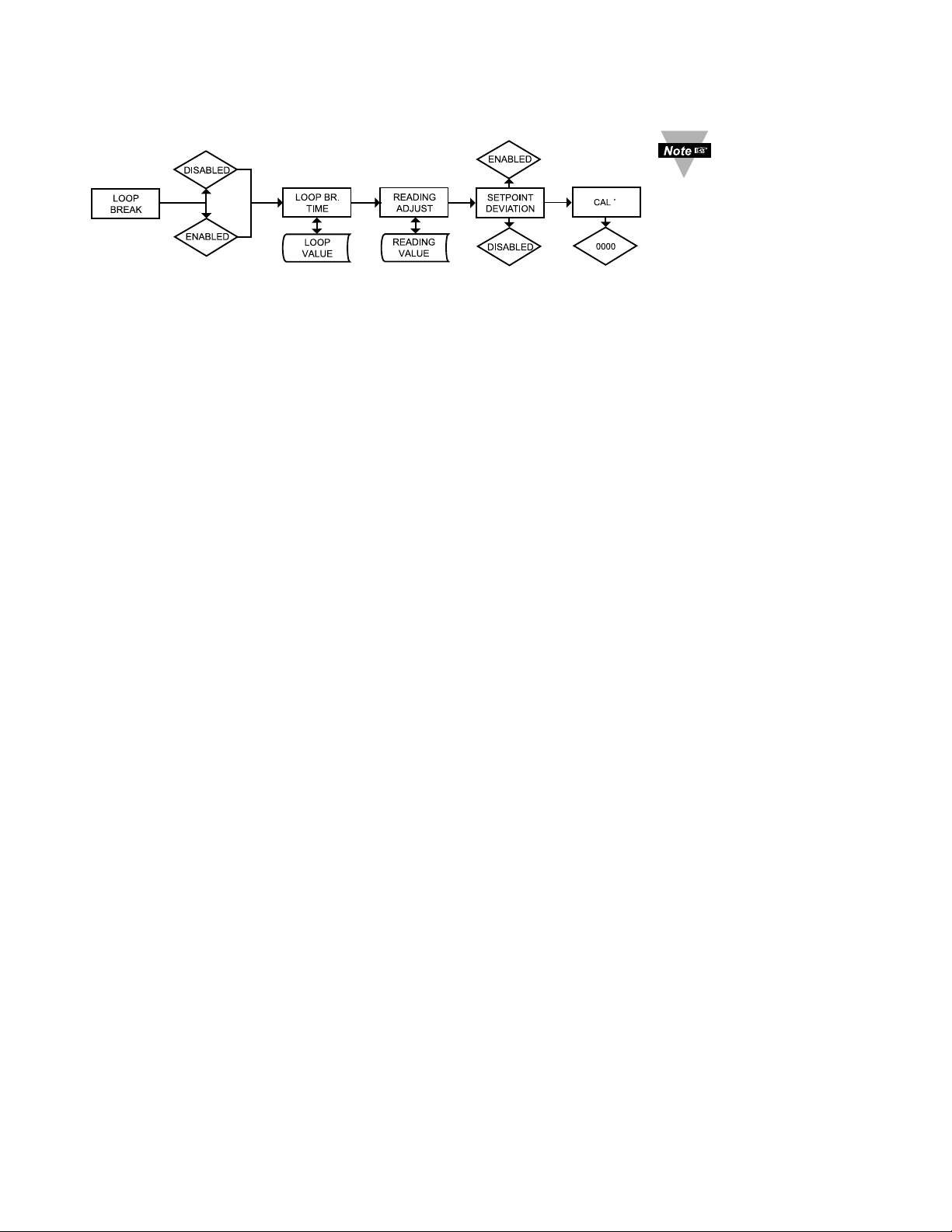
3.2.8 Loop Break Time/Field Calibration
Figure 3.7 Flow Chart for Loop Break Time/Field Calibration
ENTER LOOP BREAK TIME MENU:
Press
a
1) Press a, if necessary, until
CNFG
prompt appears.
Press
d
2) Display advances to
INPT
Input Menu.
Press
a
3) Press a, if necessary, until Display advances to
LOOP
Loop
Break Time Menu.
Press
d
4) Display advances to Loop Break Time
ENBL
Enable or
DSBL
Disable Submenu and flashes the previous selection.
LOOP BREAK ENABLE/DISABLE SUBMENU:
Press b 5) Scroll through the available selections:
ENBL
or
DSBL
.
Press
d
6) Display shows
STRD
stored message momentarily and then
advances to
B.TIM
Loop Break Time Value Submenu.
Loop Break is an additional safety feature intended to monitor the rate of change of the
process value, while approaching the SP1. It is strictly intended as an additional warning
system, therefore its use is entirely optional. An active Loop Break will cause the Process
Value digits to blink in a rotating pattern. If the process value reaches the set point the
blinking will stop and
B.TIM
is completed successfully, otherwise
BR.AL
Break Alarm
warning will flash, and Output 1 will be turned off.
LOOP BREAK TIME VALUE SUBMENU:
Press
d
7) Display flashes 1stdigit of previous Loop Value.
Press b& c8)
Press band cbuttons to enter a new Loop Value
(0 to 99.59).
Press
d
9) Display shows
STRD
stored message momentarily and then
advances to
R.ADJ
Reading Adjust Submenu.
Loop Break Time Value allows the user to determine the time interval in MM:SS (from
zero to 99 minutes and 59 seconds) that the Process Value changes at least 10 counts
or if the Input Type is either RTD or Thermocouple, the value changes 4° Fahrenheit or
2° Celsius. At the specified time interval, if the process value change is less than the
stated rate, flashing
B.TIM
will be displayed, the output 1 will be de-energized, and
Alarm 1 energized. Loop break time will be disabled when the Process Value (PV) enters
the control band.
It is required
that you put
the controller
in the Standby Mode
for any configuration
change other than Set
Points & Alarms.
Page 36
32
READING ADJUST SUBMENU:
Press
d
10) Display flashes 1stdigit of previous reading adjust value.
Press b& c11) Press band cbuttons to enter a new Reading Adjust value
(-1999 to 9999).
Press
d
12) Display shows
STRD
stored message momentarily and then
advances to
SP.DV
Setpoint Deviation Menu.
Reading Offset Adjust allows the user to fine tune a minor error of the transducer,
however some applications may require a large offset adjust.
(Displayed Process Value = Measured Process Value ± R.ADJ).
Reading Adjust is adjustable between -1999 to 9999. Note: For Temperature reading
only, not Process.
SETPOINT DEVIATION ENABLE/DISABLE SUBMENU:
Press
d
13) Display advances to Setpoint Deviation
ENBL
Enable or
DSBL
Disable Submenu and flashes the previous selection.
Press
b
14) Scroll through the available selections:
ENBL
or
DSBL
.
Press
d
15) Display shows
STRD
stored message momentarily and then
advances to the
CAL1
Menu.
Setpoint Deviation Submenu, if “enabled”, allows changes to Setpoint 1 to be made
automatically to Setpoint 2. This mode is very helpful if the Process Value changes often.
In Setpoint Deviation Mode, set SP2 a certain number of degrees or counts away from
SP1 - this relation remains fixed when SP1 is changed. For instance: Setting SP1=200
and SP2=20 and enabling
SP.DV
means that the absolute value of SP2=20. Moving SP1
to 300, the absolute value of SP2 becomes 320.
THERMOCOUPLE FIELD CALIBRATION SUBMENU:
RTD and Process are perfectly calibrated. This section is applicable to
Thermocouple (TC) calibration only.
Be sure that the TC being used to calibrate the meter is of the type
selected in the TC submenu. Place the TC in an ice-bath (or other
0°C / 32°F environment). In ambient temperature conditions: connect the
TC to the meter, apply power to the meter.
CAUTION: Do not proceed with TC calibration unless the above conditions
have been in effect for at least one hour.
Press
a
16) Display shows
CAL1
.
Press
d
17) Display shows flashing
0000
.
Press
a
18) Display will still show flashing
0000
.
Press
d
19) Display shows
OUT1
(meaning Calibration is complete)
*If you accidently engage the flashing
0000
(CAL° alert) simply re-press
the last button you pressed, to avoid unintentionally mis-calibrating your meter.
°
CAUTION: Do not perform the following steps until you fully
understand this entire section.
°
Page 37
33
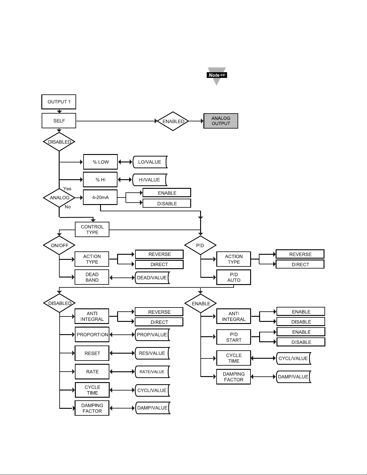
3.2.9 Output 1
This unit is equipped with three physical outputs that can only be configured as
follows:
a) Alarm 1, Alarm 2 & Analog Output
b) Output 1, Alarm 2 & Analog Output
Figure 3.8 Flow Chart for Output 1
It is required that you put
the controller in the
Standby Mode for any
configuration change other
than Set Points & Alarms.
Page 38

34
ENTER OUTPUT 1 MENU:
Press
a
1) Press a, if necessary, until
CNFG
prompt appears.
Press
d
2) Display advances to
INPT
Input Menu.
Press
a
3) Press a, if necessary, until Display advances to
OUT1
Output
1Menu.
Press
d
4) Display advances to
SELF
Self Submenu.
SELF SUBMENU:
The Self Option allows the output of the instrument to be controlled manually
from the front panel.
Press
d
5) Display flashes the current setting of Self,
ENBL
Enabled or
DSBL
Disabled.
Press
b
6) Press the bbutton to select between Enable and Disable.
Press
d
7) If Self
ENBL
Enabled was selected, display shows
STRD
stored message momentarily and then advances to the next
menu (Output 1 setting is completed).
The output is now under the direct control of the operator and
can be adjusted in the Run Mode (
M00.0
to
M99.9
), by
pressing the band cbuttons, where M calls for the Manual
(Self) Control. For example, setting of
M50.0
of an Analog
Output of
0 to 10 Vdc would produce roughly 5 Vdc at the output.
8) If Self
DSBL
Disabled was selected, display shows
STRD
stored message momentarily and then advances to
oPLO
Minimum/Percent Low Submenu of Output 1 Menu.
There is a shorter way to Enable or Disable Self Mode. From a Run
Mode, press dand then press a. Self Mode is Enabled now. Press bor
c
to display MXX.X. To disable Self, press dand then press a. Display
goes to the Run Mode. Self Mode is Disabled now.
MINIMUM/PERCENT LOW SUBMENU:
Specify in percent, the minimum value (0000) for control output. If the output is
analog proportional (Current or Voltage), then the minimum voltage or current, in
percent, is specified. If the output is time proportional (Relay, SSR or Pulse),
then the minimum duty-cycle, in percent, is specified.
Press
d
9) Display flashes 1st digit of previous “Percent Low” setting.
Press b& c10) Use band cbuttons to enter a new value for “Percent Low”.
Press
d
11) Display shows
STRD
stored message momentarily and then
advances to
oPHI
Maximum/Percent High Submenu.
Page 39

35
MAXIMUM/PERCENT HIGH SUBMENU:
Specify in percent, the maximum value (99) for control output. If the output is
analog proportional (Current or Voltage), then the maximum voltage or current, in
percent, is specified. If the output is time proportional (Relay, SSR, or Pulse),
then the maximum duty-cycle, in percent, is specified.
Press
d
12) Display flashes 1
st
digit of previous “Percent High” setting.
Press b& c13) Use band cbuttons to enter a new value for “Percent High”.
Press
d
14) Display shows
STRD
stored message momentarily and then
advances to
CTRL
Control Type Submenu.
Example: On an Analog Output of 0~10 Vdc, a setting of %LO = 10 and %HI = 90,
cause the minimum on the control output to be 1 V and the maximum on the
control output to be 9 V. The same setting on a time proportional output, will
cause 10% duty cycle for the minimum control output and 90% duty cycle for
maximum control output. To disable %LO/HI, set LO to 00 and HI to 99. If
%LO/HI
is at other values than the default (%LO = 00, %HI = 99),
SOAK
is disabled.
CONTROL TYPE OUTPUT:
(Relay, SSR, or Pulse)
Press
d
15) Display flashes
ON.OF
On/Off or
PID
Proportional, Integral,
Derivative.
Press
b
16) Scroll through the available selections: “ON/OFF” or “PID”.
Press
d
17) Display flashes
STRD
stored message momentarily and
then advances to
AçTN
only, if it was changed, otherwise press
a to advance to
AçTN
Action Type Submenu.
The ON/OFF control is a coarse way of controlling the process. The “Dead
Band” improves the cycling associated with the On/Off control.
The PID control is best for processes where the set point is continuously
changing and/or a tight control of the process variable is required. PID control
requires tuning and adjustment of the "Proportional", "Integral or Reset" and
"Derivative or Rate" terms by a trial-and-error method.
The instrument provides an "Auto Tuning" feature making the tuning process
automatic, possibly optimum.
Page 40
36
ACTION TYPE SUBMENU:
The error that results from the measurement of the Process Variable may be
positive or negative since it may be greater or smaller than the Setpoint. If a
positive error should cause the instrument output to increase (i.e. cooling), it would
be called Direct Acting. If a negative error should cause the output to increase
(i.e. heating), it would be called Reverse Acting.
Press
d
18) Display flashes
DRçT
Direct or
RVRS
Reverse.
Press
b
19) Scroll through the available selections: “Direct” or “Reverse”.
Press
d
20) Display shows
STRD
stored message momentarily and then
advances to
AUTo
only, if it was changed, otherwise press ato
advance to
AUTo
Auto PID Submenu (if PID Control Type was
selected).
If “ON/OFF” was selected in the Control Type, the display skips
to the Dead Band Submenu.
AUTO PID SUBMENU:
Press
d
21) Display flashes
ENBL
or
DSBL
.
Press
b
22)
Scroll through the available selections: “Enable” or “Disable”.
Press
d
23) Display shows
STRD
stored message momentarily and then
advances to
ANTL
only, if it was changed, otherwise press ato
advance to
ANTL
Anti Integral Submenu.
If “Enabled”, the controller can determine, by enabling Start PID, the
optimum values for the three adjustments — Proportional, Reset and
Rate corresponding to P, I, and D. These values may be changed once
the Auto Tuning is complete.
If “Disabled” is selected, the user will manually enter these three
adjustment values. If you want the instrument to do the Auto PID and the
P , PI or PID, first select Auto Disable and enter 0000 for unwanted
parameter. i.e. for PI enter 0000 for the rate.
ANTI INTEGRAL SUBMENU:
Press
d
24) Display flashes
ENBL
or
DSBL
.
Press
b
25) Scroll through the available selections: “Enable” or “Disable”.
Press
d
26) Display shows
STRD
stored message momentarily and then
advances to
STRT
only, if it was changed, otherwise press ato
advance to
STRT
to Start Auto Tune PID Submenu (If Auto PID
was Enabled).
If Auto PID was disabled display advances to
PRoP
Proportional Band Submenu.
Page 41
37
If Anti Integral (Anti Windup) Submenu “Enabled”, this feature allows
the error term outside the proportional band to be calculated and
accumulated for integration. This may be an important feature in
applications where fast response time is desirable.
START AUTO TUNE PID:
Press
d
27) Display flashes
ENBL
or
DSBL
.
Press
b
28) Scroll through the available selections: “Enable” or “Disable”.
Press
d
29) Display shows
STRD
stored message momentarily and then
advances to
CYCL
only, if it was changed, otherwise press ato
advance to
CYCL
Cycle Time Submenu.
If “Enabled”, the controller is ready to calculate P, PI or PID parameters.
The instrument performs this by activating the output and observing the
delay and rate at which the Process Value changes. The setpoints must
be at least 18°F or 10°C above the (PV) Process Value in order to
perform Auto Tune, otherwise an error message will be displayed.
To start Auto Tune PlD select PID, enable Auto PID and enable Start PID.
Sometimes Auto PID parameter needs fine tuning i.e. for each 5°F over
shoot increase the Proportional Band (PB) by 15% and for each ±1°F
fluctuation at the Setpoint (SP) increase reset by 20%.
Once started, display shows A.TUN with letters blinking in the rotating
pattern. When auto tune stops, display will show process value. Do not
perform any operations or settings before first stopping Auto Tune. Any
alarms or other output is disabled during Auto Tune.
If “AUTO PID” was “DISABLED”, the display will show the following
three submenus. This allows the user to manually enter values for
Proportional, Reset and Rate terms corresponding to P, I, and D. It also
can be used for Auto PID for disabling unwanted parameter i.e. PI enter
0000 for Rate.
PROPORTIONAL BAND SUBMENU:
Press
d
30) Display flashes 1
st
digit of the previous P
PRoP
Proportional
band value.
Press b& c31) Press band cbuttons to enter a new “Proportional Band”
value.
Press
d
32) Display shows
STRD
stored message momentarily and then
advances to
REST
only, if it was changed, otherwise press ato
advance to
REST
Reset Setup Submenu.
Proportional Band is in degrees of temperature or counts of process. Proportional
Band is defined, as the change in the instrument input to cause a 100% change
in the controller output.
Page 42

38
RESET SETUP SUBMENU:
Press
d
33) Display flashes 1
st
digit of the previous I
REST
Reset value.
Press b& c34) Press band cbuttons to enter a new “Reset” value.
Press
d
35) Display shows
STRD
stored message momentarily and then
advances to
RATE
only, if it was changed, otherwise press ato
advance to
RATE
Rate Setup Submenu.
Reset unit is in seconds 0-3999.
RATE SETUP SUBMENU:
Press
d
36) Display flashes 1
st
digit of previous D
RATE
Rate value.
Press b& c37) Press band cbuttons to enter a new
RATE
value.
Press
d
38) Display shows
STRD
stored message momentarily and then
advances to the
CYCL
only, if it was changed, otherwise press
a
to advance to
CYCL
Cycle Time submenu for RTD and
Thermocouple types.
Rate unit is in seconds 000.0-399.9.
If the Output 1 is Analog Option the display skips to Damping
Factor.
CYCLE TIME SUBMENU:
Press
d
39) Display flashes 1
st
digit of the previous
CYCL
Cycle Time
value.
Press b& c40) Press band cbuttons to enter a new “Cycle Time” value.
(1 to 199 seconds)
Press
d
41) Display shows
STRD
stored message momentarily and then
advances to
DPNG
only, if it was changed, otherwise press ato
advance to
DPNG
Damping Factor Submenu.
A Cycle Time selected between 1 and 199 seconds determines the total On/Off
time of each proportional cycle. For example, a 15 second cycle time means that
every 15 seconds the output will turn on for part or all of the cycle. For Relay
control outputs, do not select a cycle time of less than 7 seconds or the relays’
lifetime will be shortened. For a cycle time of less than 7 seconds select SSR or
DC pulse. Use an external SSR with the DC pulse option for higher currents
(higher than 1 Amp).
Page 43

39
DAMPING FACTOR SUBMENU:
Press
d
42) Display flashes the previous “Damping Factor” selection.
Press
b
43) Scroll through the available selections:
0000,0001,0002
,
0003,0004,0005,0006,0007
.
Press
d
44) Display flashes
STRD
stored message and then advances
to
ANLG
only, if it was changed, otherwise press ato advance
to
ANLG
Analog Output Menu.
Damping Factor is a measure of speed, overshoot, and undershoot in which the
process variable responds to the output changes of the instrument, which were
used during the Auto Tune. This value is typically set to the ratio of Rate to
Reset. This Default value is (0003). For fast response time, this value should be
decreased while for slow response time it should be increased.
The "DEADBAND" Submenu will only appear if "ON/OFF" was
selected from the "Control Type" Menu.
DEADBAND SUBMENU:
Press
d
45) Display flashes 1
st
digit of the previous
DEAD
Deadband
value.
Press b& c46) Press band cbuttons to enter a new “Deadband” value.
Press
d
47) Display shows
STRD
stored message and then advances to
ANLG
only, if it was changed, otherwise press ato advance to
ANLG
Analog Output Menu.
Dead Band units are the same as Proportional Band units.
The Dead Band or neutral zone is the number of degrees or counts
(if Input Type is Process) around the set point which the Process Variable
must pass above or below the set point, before the output changes state.
Page 44
40
3.2.10 Analog Output (Retransmission)
This unit is equipped with three physical outputs that can only be configured as
follows:
a) Alarm 1, Alarm 2 & Analog Out
b) Output 1, Alarm 2 & Analog Out
Analog Output is available only if the Analog Output option board is factory
installed.
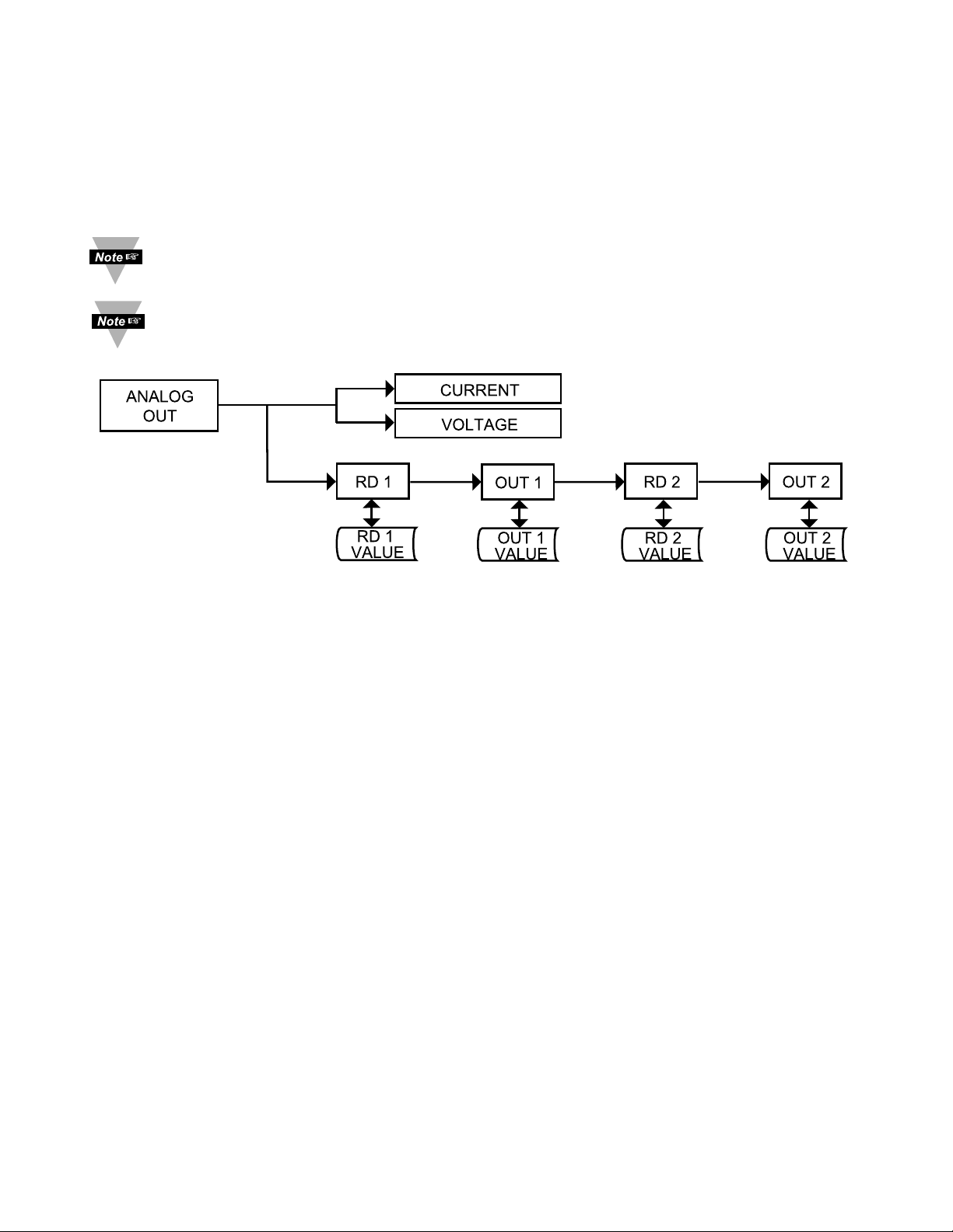
Figure 3.9 Flow Chart for Analog Output (Retransmission)
ENTER ANALOG OUTPUT MENU:
Press
a
1) Press a, if necessary, until
CNFG
prompt appears.
Press
d
2) Display advances to
INPT
Input Menu.
Press
a
3) Press a, if necessary, until Display advances to
ANLG
Analog Output Menu.
Press
d
4) Display advances to Analog Output
CURR
or
VoLT
Current/Voltage Submenu and flashes the previous selection.
CURRENT/VOLTAGE SUBMENU:
Press
d
5) Display flashes
CURR
Current or
VoLT
Voltage.
Press
b
6) Scroll through the available selection: Current or Voltage.
(Example
VoLT
).
Press
d
7) Display shows
STRD
stored message momentarily and then
advances to
RD1
Submenu only if it was changed, otherwise
press ato advance to
RD1
Reading 1 Submenu.
It is required that you put the controller in the Standby Mode for any
configuration change other than Set Points & Alarms.
Page 45

41
READING 1:
Press
d
8) Display flashes 1
st
digit of previous “Reading 1” value.
Press b& c9) Enter “Reading 1” value. (Example 0000).
Press
d
10) Display advances to
OUT.1
Out 1 Submenu.
OUT 1:
Press d 11) Display flashes 1
st
digit of previous “Out 1” value.
Press b & c 12) Enter “Out 1” value. (Example 00.00).
Press d 13) Display advances to
RD2
Reading 2 Submenu.
READING 2:
Press
d
14) Display flashes 1
st
digit of previous “Reading 2” value.
Press b& c15) Enter “Reading 2” value. (Example 9999).
Press
d
16) Display advances to
OUT.2
Out 2 Submenu.
OUT 2:
Press
d
17) Display flashes 1
st
t
digit of previous “Out 2” value.
Press b& c18) Enter “Out 2” value. (Example 10.00)
Press
d
19) Display advances to the
ALR2
Alarm 2 Menu.
The above example is for 0-10 V of the entire range of the Process Input
and Analog Output. For 0-20 mA output you need to set “Analog Type” to
Current and OUT 2 to 20.00.
Page 46
42
3.2.11 Ramp & Soak
Alarm must be DISABLED if Ramp is ENABLED.
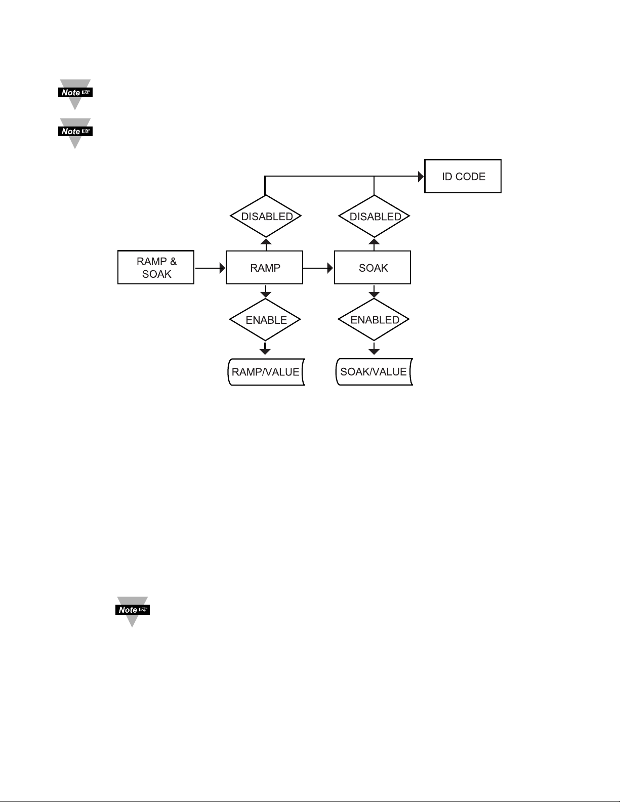
Figure 3.10 Flow Chart for Ramp and Soak
ENTER RAMP AND SOAK MENU:
Press
a
1) Press a, if necessary, until
CNFG
prompt appears.
Press
d
2) Display advances to
INPT
Input Menu.
Press
a
3) Press a, if necessary, until Display advances to
RAMP
Ramp
and
SOAK
Soak Menu.
RAMP ENABLE/DISABLE SUBMENU:
Press
d
4) Display advances to “Ramp Enable/Disable” Submenu and
flashes
ENBL
or
DSBL
.
Press
b
5) Scroll through the available selections: “Enable” or “Disable”.
Press
d
6) Display shows
STRD
stored message momentarily and then
advances to
SOAK
Soak Enable/Disable Menu.
If
RAMP
Disable was selected, display skips to the next menu
item (ID Code).
SOAK ENABLE/DISABLE SUBMENU:
Press
d
7) Display flashes
ENBL
or
DSBL
.
Press
b
8) Scroll through the available selections: “Enable” or “Disable”.
Press
d
9) Display shows
STRD
stored message momentarily and then
advances to “Ramp Value” Submenu.
It is required that you put the controller in the Standby Mode for any
configuration change other than Set Points & Alarms.
Page 47

43
Ramp & Soak provides users with the flexibility to slowly bring the Process
Variable (PV) to the desired setpoint. Ramp & Soak values are specified in
HH.MM format. The Ramp value indicates the time specified to bring the process
variable to Setpoint 1 (SP1). Once the set point is reached, the PID takes over
and the Process Variable will be controlled at the desired set point indefinitely. If
Soak is enabled, PID will control the Process Variable at the specified Setpoint
for the duration of Soak time and then will turn off Output 1. To start a new
Ramp/Soak cycle, reset the instrument by pressing aand then cbutton.
An active Ramp/Soak will change SP1 one degree above the PV and will cause
the most significant digit to blink. The SP1 will be incremented by one degree
until it reaches the original SP1. The minimum Ramp time must be at least twice
the time that it will take the PV to reach the Setpoint Value (SV) with OUT 1 fully
ON.
RAMP VALUE SUBMENU:
Press
d
10) Display flashes 1
st
digit of previous stored “Ramp Value”.
Press b& c11) Press band cbuttons to enter a new “Ramp Value”.
Press
d
12) Display shows
STRD
stored message momentarily and then
advances to “Soak Value” Submenu.
SOAK VALUE SUBMENU:
Press
d
13) Display flashes 1
st
digit of previous stored “Soak Value”.
Press b& c14) Press band cbuttons to enter a new “Soak Value”.
Press
d
15) Display shows
STRD
stored message and advances to the
ID
ID Code Menu.
The Ramp and Soak time is 00:00 to 99:59 i.e. HH.MM. (from zero to 99 hours
and 59 minutes) During Ramp & Soak do not perform any operations or settings
before first stopping it. Any alarms or other output are disabled during this time.
To stop Ramp & Soak first put instrument into Standby Mode, then go to Ramp &
Soak Menu and disable it.
Page 48
44
3.2.12 ID CODE
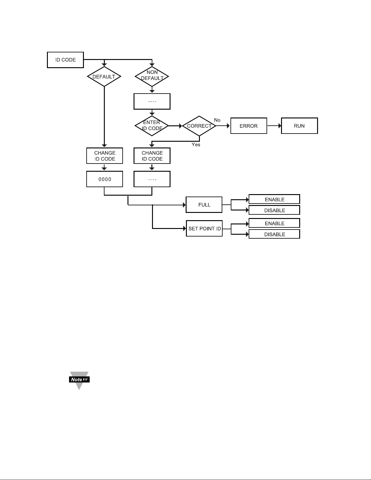
Figure 3.11 Flow Chart for ID Code
ENTER ID CODE MENU:
Press
a
1) Press a, if necessary, until
CNFG
prompt appears.
Press d 2) Display advances to
INPT
Input Menu.
Press
a
3) Press a, if necessary, until Display advances to
ID
ID Code
Menu.
ENTERING OR CHANGING YOUR (NON-DEFAULT) ID CODE:
Press d 4) Display advances to
____
with 1
st
under score flashing.
Press b& c5) Press band cto enter your 4-digit “ID Code” number.
Press d 6) Display advances to
CH.ID
Change ID Code Submenu.
If entered “ID Code” is incorrect display shows
ERRo
Error
message momentarily and then skips to the Run Mode.
Press
d
7) Display flashes the first digit of previous entered “ID Code”
number.
Press b& c8) Press band cbuttons to enter your new “ID Code” number.
Press
d
9) Display shows
STRD
stored message momentarily and then
advances to the
FULL
Full Security Submenu.
Page 49
45
ENTERING OR CHANGING YOUR (DEFAULT) ID CODE:
Enter
ID
menu (Repeat steps from 1 to 3).
Press
d
10) Display advances to
CH.ID
Change ID Code Submenu.
Press
d
11) Display shows
0000
message with flashing 1
st
digit.
If you want to change your default “ID Code” you can do it now,
otherwise press aand menu will skip to
FULL
Full Security
Submenu.
Press b& c12) Press band cbuttons to enter your new “ID Code” number.
Press
d
13) Display shows
STRD
stored message momentarily and then
advances to the
FULL
Full Security Submenu.
FULL SECURITY LEVEL SUBMENU:
Press
d
14) Display flashes
ENBL
Enable or
DSBL
Disable.
Press
b
15) Scroll through the available selections: “Enable” or “Disable”.
Press
d
16) Display shows
STRD
stored message momentarily and then
advances to
SP.ID
Setpoint/ID Submenu.
If "Full" Security Level is "Enabled" and the user attempts to
enter the Main Menu, they will be prompted for an ID Code. The
ID Code should be correct to enter the instrument Menu item.
SETPOINT/ID SECURITY LEVEL SUBMENU:
This Security Level can be functional only if
FULL
Security
Level is Disabled.
Press
d
17) Display flashes
ENBL
Enable or
DSBL
Disable.
Press
b
18) Scroll through the available selections: “Enable” or “Disable”.
Press
d
19) Display shows
STRD
stored message momentarily and then
advances to
COMM
Communication Submenu.
If "Setpoint/ID" Security Level is "Enabled" and the user
attempts to advance into the
CNFG
Configuration Menu, he will
be prompted for ID Code number. The ID Code should be
correct to proceed into the Configuration Menu, otherwise
display will show an Error and skip to the Run Mode.
If “Full” and “Setpoint/ID” Security Levels are "Disabled", the
ID code will be “Disabled” and user will not be asked for ID
Code to enter the Menu items (“ID” Submenu will not show up in
“ID/Setpoint” Menu).
Page 50
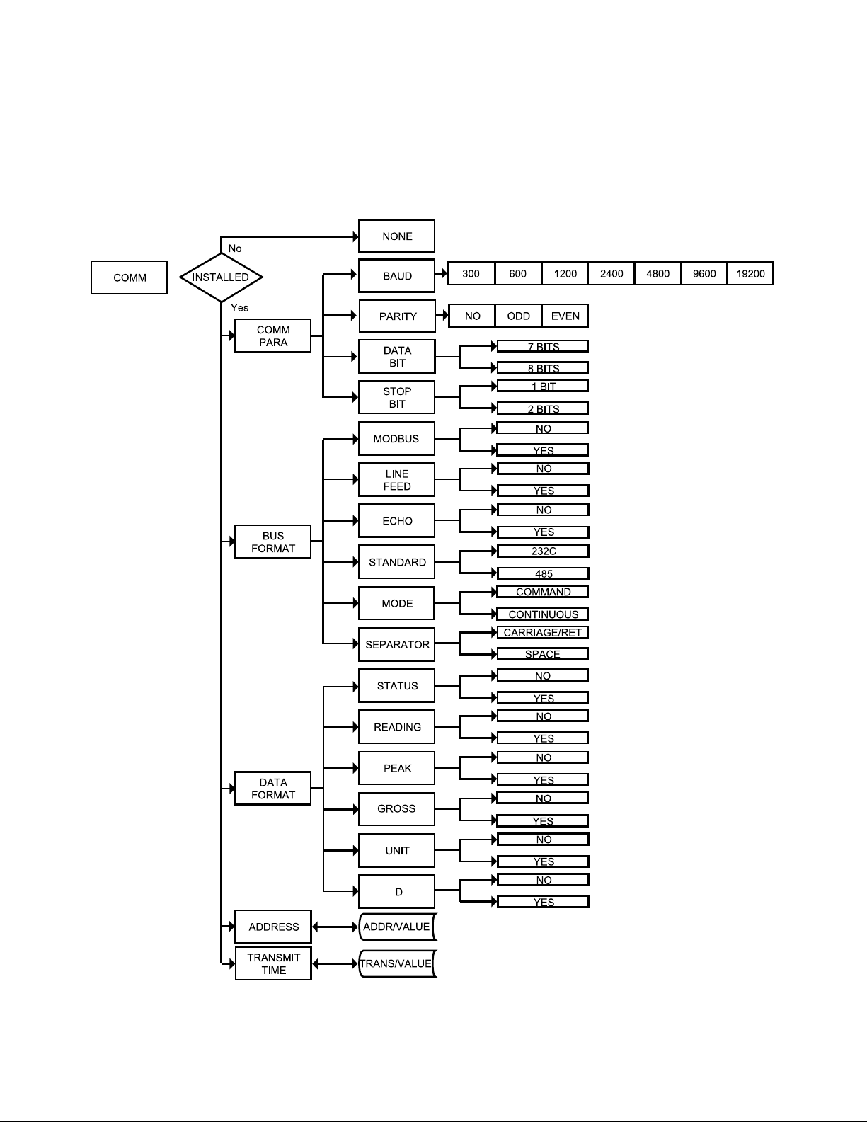
46
3.2.13 COMMUNICATION OPTION
Purchasing the controller with Serial Communications permits an instrument to be
configured or monitored from an IBM PC compatible computer using software
available at the website listed on this manual or on the CD-ROM enclosed with
your shipment. For complete instructions on the use of the Communications
Option, refer to the Serial Communications Reference Manual.
Figure 3.12 Flow Chart for Communication Option
Page 51

47
ENTER COMMUNICATION OPTION MENU:
Press
a
1) Press a, if necessary, until
CNFG
prompt appears.
Press
d
2) Display advances to
INPT
Input Menu.
Press
a
3) Press a, if necessary, until Display advances to
COMM
Communication Options Menu.
Press
d
4) Display advances to
C.PAR
Communication Parameters
Submenu.
If Communication Option is not installed, the display shows
NONE
and skips to the Color Display Menu.
COMMUNICATION PARAMETERS SUBMENU:
Allows the user to adjust Serial Communications Settings of the instrument.
When connecting an instrument to a computer or other device, the
Communications Parameters must match. Generally the default settings
(as shown in Section 5) should be utilized.
Press
d
5) Display advances to
BAUD
Baud Submenu.
BAUD SUBMENU:
Press
d
6) Display flashes previous selection for
BAUD
value.
Press
b
7) Scroll through the available selections:
300_, 600_, 1200
,
2400, 4800
,
9600, 19.2K
.
Press
d
8) Display shows
STRD
stored message momentarily and then
advances to
PRTY
only, if it was changed, otherwise press ato
advance to
PRTY
Parity Submenu.
PARITY SUBMENU:
Press
d
9) Display flashes previous selection for “Parity”.
Press
b
10) Scroll through the available selections: NO, ODD, EVEN.
Press
d
11) Display shows
STRD
stored message momentarily and then
advances to
DATA
only, if it was changed, otherwise press ato
advance to
DATA
Data Bit Submenu.
DATA BIT SUBMENU:
Press
d
12) Display flashes previous selection for “Data Bit”.
Press
b
13) Scroll through the available selections: 7-BIT, 8-BIT.
Press
d
14) Display shows
STRD
stored message and then advances to
STOP
only, if it was changed, otherwise press ato advance to
STOP
Stop Bit Submenu.
Page 52

48
STOP BIT SUBMENU:
Press
d
15) Display flashes previous selection for “Stop Bit”.
Press
b
16) Scroll through the available selections:
1-BIT, 2-BIT
.
Press
d
17) Display shows
STRD
stored message momentarily and then
advances to
BUS.F
only, if it was changed, otherwise press ato
advance to
BUS.F
Bus Format Submenu.
BUS FORMAT SUBMENU:
Determines Communications Standards and Command/Data Formats for
transferring information into and out of the controller via the Serial
Communications Bus. Bus Format submenus essentially determine how and
when data can be accessed via the Serial Communications of the device.
Press
d
18) Display advances to
M.BUS
Modbus Submenu.
MODBUS PROTOCOL SUBMENU:
Press
d
19) Display flashes previous selection for
M.BUS
.
Press
b
20) Scroll through the available selections: NO, YES.
Press
d
21) Display shows
STRD
stored message momentarily and then
advances to
_LF_
only, if it was changed, otherwise press ato
advance to
_LF_
Line Feed submenu.
To select iSeries Protocol, set Modbus submenu to “No”.
To select Modbus Protocol, set Modbus submenu to “Yes”.
If Modbus Protocol was selected, the following Communications
Parameters must be set as: No Parity, 8-bit Data Bit, 1-Stop Bit. Do not
attempt to change these parameters.
LINE FEED SUBMENU:
Determines if data sent from the instrument will have a Line Feed appended to
the end - useful for viewing or logging results on separate lines when displayed
on communications software at a computer.
Press
d
22) Display flashes previous selection for “Line Feed”.
Press
b
23) Scroll through the available selections: NO, YES.
Press
d
24) Display shows
STRD
stored message momentarily and then
advances to
ECHO
only, if it was changed, otherwise press ato
advance to
ECHO
Echo Submenu.
ECHO SUBMENU:
When valid commands are sent to the instrument, this determines whether the
command will be echoed to the Serial Bus. Use of echo is recommended in most
situations, especially to help verify that data was received and recognized by the
controller.
Page 53

49
Press
d
25) Display flashes previous selection for “Echo”.
Press
b
26) Scroll through the available selections: NO, YES.
Press
d
27) Display flashes
STRD
stored message momentarily and then
advances to
STND
only if it was changed, otherwise press ato
advance to
STND
Communication Standard Submenu.
COMMUNICATION INTERFACE STANDARD SUBMENU:
Determines whether device should be connected to an RS232C serial port
(as is commonly used on IBM PC-compatible computers) or via an RS485 bus
connected through appropriate RS232/485 converter. When used in RS485
Mode, the device must be accessed with an appropriate Address Value as
selected in the Address Submenu described later.
Press
d
28) Display flashes previous selection for “Standard”.
Press
b
29) Scroll through the available selections: 232C, 485.
Press
d
30) Display shows
STRD
stored message momentarily and then
advances to
MoDE
only, if it was changed, otherwise press ato
advance to
MoDE
Data Flow Mode Submenu.
DATA FLOW MODE SUBMENU:
Determines whether the instrument will wait for commands and data requests
from the Serial Bus or whether the instrument will send data automatically and
continuously to the Serial Bus. Devices configured for the RS485
Communications Standard operate properly only under Command Mode.
Press
d
31) Display flashes previous selection for “Mode”.
Press
b
32) Scroll through the available selections:
CMD_
“Command”,
CoNT
“Continuous”.
Press
d
33) Display shows
STRD
stored message momentarily and then
advances to
SEPR
only, if it was changed, otherwise press ato
advance to
SEPR
Data Separation Submenu.
DATA SEPARATION CHARACTER SUBMENU:
Determines whether data sent from the device in Continuous Data Flow Mode
will be separated by spaces or by Carriage Returns.
Press
d
34) Display flashes previous selection for “Separation” Submenu.
Press
b
35) Scroll through the available selections:
SPCE
“Space” or
_çR_
“Carriage Return”.
Press
d
36) Display shows
STRD
stored message momentarily and then
advances to
DAT.F
only, if it was changed, otherwise press ato
advance to
DAT.F
Data Format Submenu.
Page 54

50
DATA FORMAT SUBMENU:
Preformatted data can be sent automatically or upon request from the controller.
Use the Data Format Submenus to determine what data will be sent in this
preformatted data string. Refer to the iSeries Communications Manual for more
information about the data format. At least one of the following suboptions must
be enabled and hence output data to the Serial Bus.
This menu is applicable for Continuous Mode of RS232 communication.
Press
d
37) Display advances to
STAT
Alarm Status Submenu.
ALARM STATUS SUBMENU:
Includes Alarm Status bytes in the data string.
Press
d
38) Display flashes previous selection for “Status” (alarm status).
Press
b
39) Scroll through the available selections: NO, YES.
Press
d
40) Display shows
STRD
stored message momentarily and then
advances to
RDNG
only, if it was changed, otherwise press ato
advance to
RDNG
Reading Submenu.
MAIN READING SUBMENU:
Includes Main Reading in the data string.
Press
d
41) Display flashes previous selection for “Reading”.
Press
b
42) Scroll through the available selections: NO, YES.
Press
d
43) Display shows
STRD
stored message momentarily and then
advances to
PEAK
only, if it was changed, otherwise press ato
advance to
PEAK
Peak Submenu.
PEAK VALUE SUBMENU:
Includes Peak Value in the data string.
Press
d
44) Display flashes previous selection for
PEAK
Submenu.
Press
b
45) Scroll through the available selections: NO, YES.
Press
d
46) Display shows
STRD
stored message momentarily and then
advances to
VALY
only, it was changed, otherwise press ato
advance to
VALY
Valle y Submenu.
VALLEY VALUE SUBMENU:
Includes Valley Value in the data string.
Press
d
47) Display flashes previous selection for “Valley”.
Press
b
48) Scroll through the available selections: NO, YES.
Press
d
49) Display shows
STRD
stored message momentarily and then
advances to
UNIT
only, if it was changed, otherwise press ato
advance to
UNIT
Te mpe rat ure Un it Sub men u.
Page 55
51
TEMPERATURE UNIT SUBMENU:
Includes a byte in the data string to indicate whether reading is in Celsius or
Fahrenheit.
Press
d
50) Display flashes previous selection for
UNIT
.
Press
b
51) Scroll through the available selections: NO, YES.
Press
d
52) Display shows
STRD
stored message momentarily and then
advances to
ADDR
only, if it was changed, otherwise press ato
advance to
ADDR
Address Setup Submenu.
ADDRESS SETUP SUBMENU:
This menu is applicable to the RS485 Option only.
Press
d
53) Display advances to “Address Value” (0000 to 0199) Submenu.
ADDRESS VALUE SUBMENU:
Press
d
54) Display flashes 1
st
digit of previously stored Address Value.
Press b& c55) Press band cto enter new “Address Value”.
Press
d
56) Display shows
STRD
stored message momentarily and then
advances to
TR.TM
only, if it was changed, otherwise press ato
advance to
TR.TM
Transmit Time Interval Submenu.
TRANSMIT TIME INTERVAL SUBMENU:
This menu is applicable if “Continuous” Mode was selected in the “Data
Flow Mode” Submenu and the device is configured as an RS232C
Standard device. Also, one or more options under the Data Format
Submenu must be enabled.
Press
d
57) Display advances to “Transmit Time Value” Submenu.
TRANSMIT TIME INTERVAL VALUE SUBMENU:
Determines the interval at which data will be emitted to the RS232 Serial Bus
when the instrument is in Continuous Data Flow Mode.
Press
d
58) Display flashes 1
st
digit of previous “Transmit Time Value” in
seconds.
Press b& c59) Press band cto enter new “Transmit Time Value”, e.g.
0030 will send the data every 30 seconds in Continuous Mode.
Press
d
60) Display shows
STRD
stored message momentarily and then
advances to
COLR
only, if it was changed, otherwise press ato
advance to
COLR
Color Display Selection Menu.
For more details, refer to the Communication Manual available at the
website listed on the cover page of this manual or on the CD-ROM
enclosed with your shipment.
Page 56
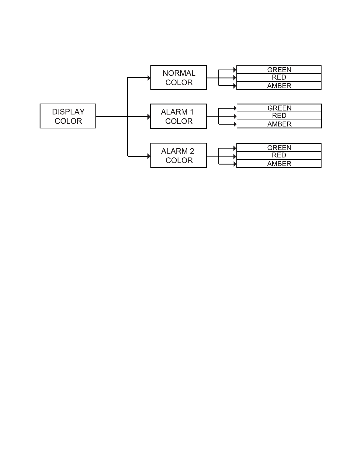
52
3.2.14 DISPLAY COLOR SELECTION
This submenu allows the user to select the color of the display.
Figure 3.13 Flow Chart for Display Color Selection
ENTER DISPLAY COLOR SELECTION MENU:
Press
a
1) Press a, if necessary, until
CNFG
prompt appears.
Press
d
2) Display advances to
INPT
Input Menu.
Press
a
3)
Press a, if necessary, until Display advances to
COLR
Display Color Selection Menu.
Press
d
4) Display advances to
N.CLR
Normal Color Submenu.
NORMAL COLOR DISPLAY SUBMENU:
Press
d
5) Display flashes the previous selection for “Normal Color”.
Press
b
6) Scroll through the available selections:
GRN, RED
or
AMBR
.
Press
d
7) Display shows
STRD
stored message momentarily and then
advances to
1.CLR
only, if it was changed, otherwise press ato
advance to
1.CLR
Alarm 1 Display Color Submenu.
The menu below allows the user to change the color of display when alarm is
triggered.
ALARM 1 DISPLAY COLOR SUBMENU:
Press
d
8)
Display flashes previous selection for “Alarm 1 Color Display”.
Press
b
9) Scroll through the available selections:
GRN, RED
or
AMBR
.
Press
d
10) Display shows
STRD
stored message momentarily and then
advances to
2.CLR
only, if it was changed, otherwise press ato
advance to
2.CLR
Alarm 2 Display Color Submenu.
Page 57

53
ALARM 2 DISPLAY COLOR SUBMENU:
Press
d
11) Display flashes previous selection for “Alarm 2 Color Display”.
Press
b
12) Scroll through the available selections:
GRN, RED
or
AMBR
.
Press
d
13) Display shows
STRD
stored message momentarily and then
momentarily shows the software version number, followed by
RST
Reset, and then proceeds to the Run Mode.
IN ORDER TO DISPLAY ONE COLOR, SET THE SAME DISPLAY
COLOR ON ALL THREE SUBMENUS ABOVE.
If user wants the Display to change color every time when both Alarm 1
and Alarm 2 are triggered, the Alarm values should be set in such a way
that Alarm 1 value is always on the top of Alarm 2 value, otherwise value
of Alarm 1 will overwrite value of Alarm 2 and Display Color would not
change when Alarm 2 is triggered.
Example 1:
Output 1 & Alarm 2
: SSR
Alarm Setup: Absolute, Above, Alarm 2 HI Value “ALR.H” = 200, Alarm 1
HI Value “ALR.H” = 400
Color Display Setup: Normal Color “N.CLR” = Green, Alarm 1 Color
“1.CLR” = Amber, Alarm 2 Color “2.CLR” = Red
Display Colors change sequences:
GREEN RED AMBER
•--!
------------------------------•-----------------------------•------------------------------
!
0 AL2.H = 200 AL1.H = 400
Example 2:
Output 1 & Alarm 2
: Pulse
Alarm Setup: Absolute, Below, Alarm 2 Low Value “ALR.L” = 300, Alarm 1
Low Value “ALR.L” = 100
Color Display Setup: "N.CLR" = Green, "1.CLR" = Amber, "2.CLR" = Red
Display Colors change sequences:
AMBER RED GREEN
•
--------------•----------------------------------•------------------------------------------- --
•
0 AL1.L = 100 AL2.L = 300
! !
Page 58

54
Example 3:
Output 1: Relay, Setpoint 1: 200
Alarm 2: Relay, Setpoint 2: 200
Alarm 1 Setup
: Deviation, Band, “ALR.H” = 20
Alarm 2 Setup: Deviation, Hi/Low, “ALR.H” = 10, “ALR.L” = 5
Color Display Setup: “N.CLR” = Green, “1.CLR” = Amber, “2.CLR” = Red
Display colors change sequences:
AMBER RED GREEN GREEN RED AMBER
•--!
---------------•----------------•-------------•--------------•-------------•---------------------
!
0 180 195 200 210 220
Reset: The instrument automatically resets after the last menu of the
Configuration Mode has been entered. After the instrument resets, it
advances to the Run Mode.
Page 59

!!
Thermocouple+Lead+Resistance
"##$%&'$'()
RTD+Input+(ITS+68)
"##*!##*"###$ż +,$-./-%01$
231$43$%0$53670.8$
#9##4:!$%0$#9##4;2$<=0>.
Voltage+Input
#$,%$"##$'?1$#$,%$"$? 1$#$,%$"#$?@<
Input+Impedance
"#$Aż B%0$"##$'?
"$Aż B%0$"$%0$"#$?@<
Current+Input
#$,%$2#$'C$D!$%&'$E%(@F
Configuration
G7/HE.3./@.@
Polarity
I/7J%E(0
Step+Response
#9K$-.<$B%0$;;9;L
Decimal+Selection
M%/.1$#9"$B%0$,.'J.0(,=0.
M%/.1$#9"1$#9#"$%0$#9##"$B%0$J0%<.--$
Setpoint+ Adjustment
3";;;$,%$N;;;;$<%=/,-
Span+Adjustment
#9##"$,%$;;;;$<%=/,-
Offset+Adjustment
3";;;$,%$N;;;;
CONTROL
C<,7%/
O.>.0-.$D&.(,F$%0$@70.<,$D<%%EF
PART+4
SPECIFICATIONS
Accuracy+at+25ºC
P#9!QR$,.'J$/%'7/(E
$#9#4L$0@H$P#9#4L$0(/H.$J0%<.-(/@$-,0(7/
Resolution
"Q*#9"Q8$"#$S?$J0%<.--
Temperature+Stability
"F$OTUV$#9#5QR*QR
2F$TR$W$2!QR$DKKQXFV$#9#!QR*QR$
R%E@$Y=/<,7%/$R%'J./-(,7%/
4F$+0%<.--V$!#$JJ'*QR
NMRR
Z#$@[
CMRR
"2#$@[
A/D+Conversion
U=(E$-E%J.
Reading+Rate
4$-('JE.-$J.0$-.<%/@
Digital+Filter
+0%H0(''(\E.
Display
53@7H7,1$;3-.H'./,$]^U1
2"$''$D#9:4_F
1
¼8
DIN
"#92$''$D#95#`F
1
¼16
DIN
0.@1$H0../$(/@$('\.0$J0%H0(''(\E.
<%E%0-$B%0$J0%<.--$>(07(\E.1$-.,$J%7/,
(/@$,.'J.0(,
=0.$=/7,-
Warm+up+to+Rated+ Accuracy
4#$'7/9
INPUT
Input+T ypes
T&.0'%<%=JE.1$OTU1$C/(E%H$?%E,(H.1
C/(E%H$R=00./,
Thermocouple+T ype+(ITS90)
Y1$a1$T1$^1$O1$G1$[1$R1$M1$]
Page 60

56
ALARM 2
Relay
SPDT type, 250 Vac or 30 Vac @ 3 A
(Resistive Load)
SSR
20-265 Vac @ 0.05-0.5 A
(Resistive Load); continuous
DC Pulse
Non-Isolated; 10 Vdc @ 20 mA
OUTPUT 3
ANALOG OUTPUT (programmable)
Isolated, Retransmission 0 to 10 Vdc or
0 to 20 mA, 500 Ωmax. Accuracy is 1% of
FS, for Scaling Gain from 0.03 to
100 mV per count
Isolation is 1000 Vdc
Linearity is 0.2%
COMMUNICATIONS
(Optional in place of excitation)
RS232/RS422/RS485/MODBUS:
Selectable from menu; both ASCII and
modbus protocol selectable from menu.
Programmable 300 to 19.2 K baud;
complete programmable setup capability;
program to transmit current display, alarm
status, min/max, actual measured input
value and status.
RS485
Addressable from 0 to 199
ALARM 1 & 2 (programmable):
Type
Same as Output 1 & 2
Operation
High/low, above/below, band,
latch/unlatch, normally open/normally
closed and process/deviation; front panel
configurations
Modes
Time and Amplitude Proportional Control
Modes; selectable Manual or Auto PID,
Proportional, Proportional with Integral,
Proportional with Derivative with Antireset Windup and ON/OFF
Rate
0 to 399.9 seconds
Reset
0 to 3999 seconds
Cycle Time
1 to 199 seconds; set to 0 for ON/OFF
operation
Gain
0.5 to 100% of span; Setpoints 1 or 2
Damping
0000 to 0008
Soak
00.00 to 99.59 (HH:MM), or OFF
Ramp to Setpoint
00.00 to 99.59 (HH:MM), or OFF
Auto Tune
Operator initiated from front panel
CONTROL OUTPUT 1
Configurable as Alarm 1, On/Off, PID
and Ramp and Soak
Relay
SPDT type, 250 Vac or 30 Vac @ 3 A
(Resistive Load);
SSR
20-265 Vac @ 0.05-0.5 A
(Resistive Load); continuous
DC Pulse
Non-Isolated; 10 Vdc @ 20 mA
Page 61

57
EXCITATION
(optional in place of Communication)
24 Vdc @ 25 mA
Not available for Low Power Option
INSULATION
Power to Input/Output
2300 Vac per 1 min. test
1500 Vac per 1 min. test
(Low Voltage/Power Option)
Power to Relays/SSR Outputs
2300 Vac per 1 min. test
Relays/SSR to Relay/SSR Outputs
2300 Vac per 1 min. test
RS232/485 to Inputs/Outputs
500 Vac per 1 min. test
Approvals
FM, UL, C-UL, and
see CE Approval Section
GENERAL
Line Voltage/Power
90-240 Vac +/-10%, 50-400 Hz*
110-3 75 Vdc, equivalent voltag e
5 W, power consumption
* No CE compliance above 60 Hz
Low Voltage/Power Option
20-36 Vdc, 4 W
**, power consumption
External power source must meet Safety
Agency Approvals.
**
Units can be powered safely with 24 Vac
but, no Certification for CE/UL are claimed.
External Fuse Required
Time-Delay, UL 248-14 listed:
100 mA/250 V
400 mA/250 V
(Low Voltage/Power Option)
Time-Lag, IEC 127-3 recognized:
100 mA/250 V
400 mA/250 V
(Low Voltage/Power Option)
Environmental Conditions
0 to 55°C (32 to 131°F),
90% RH non-condensing
0 to 50°C (32 to122°F) for UL only.
90% RH non-condensing
Protection
NEMA 1(Type 1) front bezel
1
⁄8
DIN
NEMA 4 (IP65) front bezel
1
⁄16
DIN
Dimensions
48 H x 96 W x 127 mm D
(1.89 x 3.78 x 5")
1
⁄8
DIN
48 H x 48 W x 127 mm D
(1.89 x 1.89 x 5")
1
⁄16
DIN
Panel Cutout
45 H x 92 W mm
(1.772" x 3.622 ")
1
⁄8
DIN
45 mm (1.772") square
1
⁄16
DIN
Weight
295 g (0.65 lb)
1
⁄8
DIN
159 g (0.35 lb)
1
⁄16
DIN
Page 62
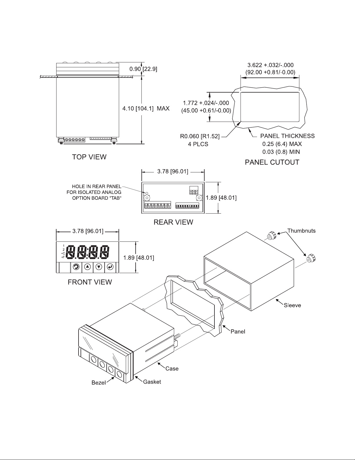
4.1
1
⁄8
DIN Mounting
58
Page 63
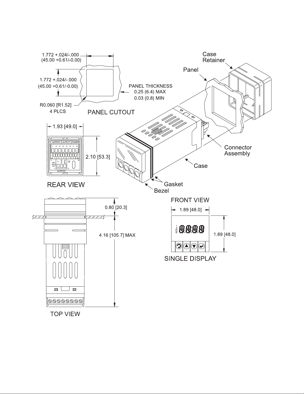
4.2
1
⁄16
DIN Mounting
59
Page 64
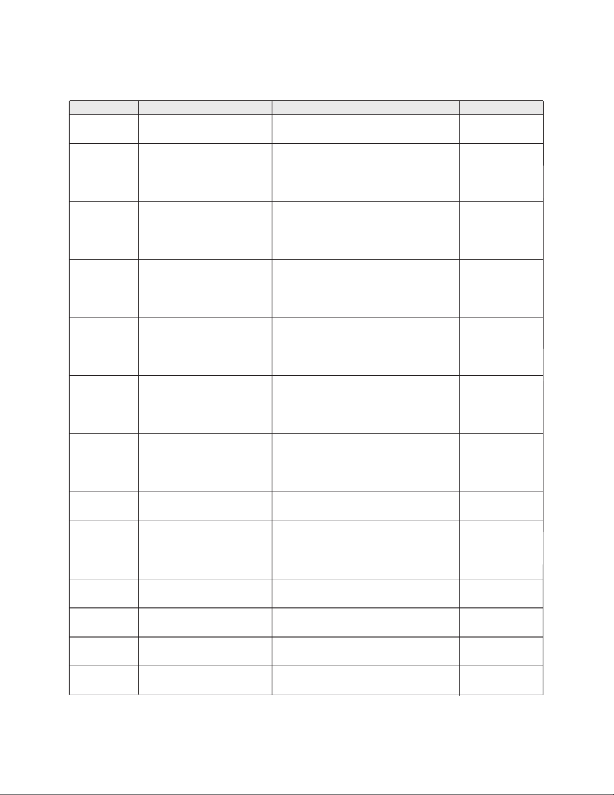
!
!
"
#
$
%
&
'
(
)
*
%#+
#,-./012304567809:;6/:8</=
>?@,:7@@A/B5,%/6?# 0 8 765 4(#
#$%&'(%&)*+&*+& ',"-.*%./!-0( -120(
'32!.*%."2--04 -1/04
',/-.*%.'"!-0( "1-0(
(56789:;
<
' '"!-.*%."3/,0( -120(
;=789:;
<
'2>2.*%.',>!04 "1?04
',>!.*%.,>-,04 -1/04
',/-.*%.'"@-0( "1-0(
(%AAB$'(%&)*+&*+& '"@-.*%.2--0( -120(
'2>2.*%.'3"-04 "1?04
'3"-.*%./>,04 -1/04
',/-.*%.',,-0( "1-0(
(56789:;' ',,-.*%."---0( -120(
(%&)*+&*+& '2>2.*%.'3!204 "1?04
'3!2.*%."?3,04 -1/04
'>-.*%.2-0( "1-0(
C*D"3E6F'C* 2-.*%."/??0( -1>0(
'>?.*%."-204 "1?04
"-2.*%.3,>-04 -1@04
'>-.*%."--0( "1-0(
C*D"-E6F'C* "--.*%."/!?0( -1>0(
'>?.*%.,",04 "1?04
,",.*%.3,"204 -1@04
,--.*%.!2-0( "1-0(
3-E6F'C*D !2-.*%."?,-0( -1>0(
!E6F'C* ,",.*%.""?204 "1?04
""?2.*%.33-?04 -1@04
>E6B'GD -.*%.,3>20( -120(
,!E6B'G 3,.*%.2,>304 -1/04
',>-.*%.'"--0( "1-0(
HIJ$%)IK'HI)IK '"--.*%."3--0( -120(
'2"?.*%.'"2?04 "1?04
'"2?.*%.,3/,04 -1/04
(0 2 1 -(0 --@ . % * . --, 'L
M#H '3,?.*%."!>,04 -1/04
C*N-1--3?>N."--.
',--.*%.?>-O(.D
'3,?.*%."!>,O4
P-1>O(.
P-1-,E.$QR
%#+
C*N.-1--3?>N.>--.%FS
',--.*%.?>-O(.D.
'3,?.*%."!>,O4
P-1!O(
P-1,E.$QR
%#+
C*N.-1--3?>N."---.%FS
',--.*%.?>-O(.D
'3,?.*%."!>,O4
P-1>O(
P-1-,E.$QR
Page 65
!"#
!"#
"$%&'()*+(,-./0(123.'204'5(673-04-/'89
:;7$2/77<'=-$!'.;"(0/.-,>"
!"#$%&%%'()#$*%%$+,-
.)%%$"+$/0%12$3
.')/$"+$*04)56
$
.)%%$"+$/0%52$3
.')/$"+$*40)56
!"#
.)%%$"+$/0%52$3$
.')/$"+$*40)56
7%&052$
7%&)8$9:;
!"#$%&%%'()#$0%%$+,-
!"#$%&%%'()#$*%%%$+,-
7%&/852
7%&/852
7%&*8$9:;
!9+<=>>
!9+<=>>
?+@"A;=
2B99=C"
%$"+$*%%$-?#$%$"+$*$?#
%$"+$*%$?:<
%$"+$)%$-D#$E$"+$)%$-D
%&%'8$9:;$7%&%'8$9AC;=$
%&%'8$9:;$7%&%'8$9AC;=$
%&%'8$9:;
Page 66
61
PART 5
FACTORY PRESET VALUES
Table 5.1 Factory preset value
MENU ITEMS FACTORY PRESET VALUES NOTES
Set Point 1 (SP1) 000.0
Set Point 2 (SP2) 000.0
Input:
Input Type (INPT) TC, type K
Reading Configuration (RDG):
Decimal Point (DEC.P) FFF.F
Temperature unit (TEMP) °F
Filter value (FLTR) 0004
Alarm 1 & 2
:
Alarm 1 (ALR1) Disable (DSBL)
Alarm 2 (ALR2) Enable (ENBL)
Absolute/Deviation (ABSO/DEV) Absolute (ABSO)
Latch/Unlatch (LTCH/UNLT) Unlatch (UNLT)
Contact Closure (CT.CL) Normally Open (N.O.)
Active (ACTV) Above (ABOV)
Alarm At Power On (A.P.ON) Disable (DSBL) Alarm 1 only
Alarm Low (ALR.L) -100.0
Alarm High (ALR.H) 400.0
LOOP:
Loop Break Time (LOOP) Disable (DSBL)
Loop Value (B.TIM) 00:59
Reading Adjust Value (R.ADJ) 000.0
Setpoint Deviation (SP.dV) Disable (DSBL)
OUTPUT 1:
Self (SELF) Disabled (DSBL)
% Low Value (%LO) 0000
% High Value (%HI) 0099
Control Type (CTRL) On/Off
Action Type (ACTN) Reverse (RVRS)
Dead Band (DEAD) 020.0
PID Auto (AUTO) Disable (DSBL)
Anti Integral (ANTI) Disable (DSBL)
Proportion Value (PROP) 020.0
Reset Value (REST) 0180
Rate Value (RATE) 0000
Cycle Value (CYCL) 0007
Damping Factor (DPNG) 0003
ANALOG OUTPUT (Retransmission)
Analog Output (ANLG) Enabled (ENBL)
Current/Voltage (CURR/VOLT) Voltage (VOLT)
Scale and Offset Reading: 0 - 999.9 cts, Output: 0 - 10 V
Page 67
62
MENU ITEMS FACTORY PRESET VALUES NOTES
Ramp & Soak (RAMP)
:
Ramp (RAMP) Disable (DSBL)
Soak (SOAK) Disable (DSBL)
Ramp Value (RAMP) 00:00
Soak Value (SOAK) 00:00
ID
:
ID Value 0000
Full ID (FULL) Disable (DSBL)
Set Point ID (ID.SP) Disable (DSBL)
Communication Parameters:
Baud Rate (BAUD) 9600
Parity (PRTY) Odd
Data bit (DATA) 7 bit
Stop Bit 1 bit
Modbus Protocol (M.BUS) No
Line Feed (LF) No
Echo (ECHO) Yes
Standard Interface (STND) RS232 (232C)
Command Mode (MODE) Command (CMD)
Separation (SEPR) Space (SPCE)
Alarm Status (STAT) No
Reading (RDNG) Yes
Peak No
Valley (VALY) No
Units (UNIT) No
Multipoint Address (ADDR) 0001
Transmit Time (TR.TM) 0016
Display Color (COLR):
Normal Color (N.CLR) Green (GRN)
Alarm 1 Color (1.CLR) Red (RED)
Alarm 2 Color (2.CLR) Amber (AMBR)
Page 68

63
PART 6
CE APPROVALS INFORMATION
This product conforms to the EMC directive 89/336/EEC amended by
93/68/EEC, and with the European Low Voltage Directive 72/23/EEC.
Electrical Safety EN61010-1:2001
Safety requirements for electrical equipment for measurement, control and laboratory.
Double Insulation
Pollution Degree 2
Dielectric withstand Test per 1 min
• Power to Input/Output: 2300Vac (3250Vdc)
• Power to Input/Output: 1500Vac (2120Vdc)
(Low Voltage dc Power Option*)
• Power to Relays/SSR Output: 2300Vac (3250Vdc)
• Ethernet to Inputs: 1500Vac (2120Vdc)
• Isolated RS232 to Inputs: 500Vac (720Vdc)
• Isolated Analog to Inputs: 500Vac (720Vdc)
• Analog/Pulse to Inputs: No Isolation
Measurement Category I
Category I are measurements performed on circuits not directly connected to the
Mains Supply (power). Maximum Line-to-Neutral working voltage is 50Vac/dc.
This unit should not be used in Measurement Categories II, III, IV.
Transients Overvoltage Surge (1.2 / 50uS pulse)
• Input Power: 2500V
• Input Power: 1500V
(Low Voltage dc Power Option*)
• Ethernet: 1500V
• Input/Output Signals: 500V
Note: *Units configured for external low power dc voltage, 20-36Vdc
EMC EN61326:1997 + and A1:1998 + A2:2001
Immunity and Emissions requirements for electrical equipment for measurement,
control and laboratory.
• EMC Emissions Table 4, Class B of EN61326
• EMC Immunity** Table 1 of EN61326
Note: **I/O signal and control lines require shielded cables and these cables
must be located on conductive cable trays or in conduits. Furthermore,
the length of these cables should not exceed 30 meters
Refer to the EMC and Safety installation considerations (Guidelines) of this manual
for additional information.
Page 69

NOTES
Page 70

NOTES
Page 71

NOTES
Page 72

WARRANTY/DISCLAIMER
OMEGA ENGINEERING, INC. warrants this unit to be free of defects in materials and workmanship for a
period of 13 months from date of purchase. OMEGA’s WARRANTY adds an additional one (1) month
grace period to the normal one (1) year product warranty to cover handling and shipping time. This
ensures that OMEGA’s customers receive maximum coverage on each product.
If the unit malfunctions, it must be returned to the factory for evaluation. OMEGA’s Customer Service
Department will issue an Authorized Return (AR) number immediately upon phone or written request.
Upon examination by OMEGA, if the unit is found to be defective, it will be repaired or replaced at no
charge. OMEGA’s WARRANTY does not apply to defects resulting from any action of the purchaser,
including but not limited to mishandling, improper interfacing, operation outside of design limits,
improper repair, or unauthorized modification. This WARRANTY is VOID if the unit shows evidence of
having been tampered with or shows evidence of having been damaged as a result of excessive corrosion;
or current, heat, moisture or vibration; improper specification; misapplication; misuse or other operating
conditions outside of OMEGA’s control. Components in which wear is not warranted, include but are not
limited to contact points, fuses, and triacs.
OMEGA is pleased to offer suggestions on the use of its various products. However,
OMEGA neither assumes responsibility for any omissions or errors nor assumes liability for
any damages that result from the use of its products in accordance with information provided
by OMEGA, either verbal or written. OMEGA warrants only that the parts manufactured by the
company will be as specified and free of defects. OMEGA MAKES NO OTHER WARRANTIES OR
REPRESENTATIONS OF ANY KIND WHATSOEVER, EXPRESSED OR IMPLIED, EXCEPT THAT OF
TITLE, AND ALL IMPLIED WARRANTIES INCLUDING ANY WARRANTY OF MERCHANTABILITY
AND FITNESS FOR A PARTICULAR PURPOSE ARE HEREBY DISCLAIMED. LIMITATION OF
LIABILITY: The remedies of purchaser set forth herein are exclusive, and the total liability of
OMEGA with respect to this order, whether based on contract, warranty, negligence,
indemnification, strict liability or otherwise, shall not exceed the purchase price of the
component upon which liability is based. In no event shall OMEGA be liable for
consequential, incidental or special damages.
CONDITIONS: Equipment sold by OMEGA is not intended to be used, nor shall it be used: (1) as a “Basic
Component” under 10 CFR 21 (NRC), used in or with any nuclear installation or activity; or (2) in medical
applications or used on humans. Should any Product(s) be used in or with any nuclear installation or
activity, medical application, used on humans, or misused in any way, OMEGA assumes no responsibility
as set forth in our basic WARRANTY/DISCLAIMER language, and, additionally, purchaser will indemnify
OMEGA and hold OMEGA harmless from any liability or damage whatsoever arising out of the use of the
Product(s) in such a manner.
RETURN REQUESTS/INQUIRIES
Direct all warranty and repair requests/inquiries to the OMEGA Customer Service Department.
BEFORE RETURNING ANY PRODUCT(S) TO OMEGA, PURCHASER MUST OBTAIN AN AUTHORIZED
RETURN (AR) NUMBER FROM OMEGA’S CUSTOMER SERVICE DEPARTMENT (IN ORDER TO AVOID
PROCESSING DELAYS). The assigned AR number should then be marked on the outside of the return
package and on any correspondence.
The purchaser is responsible for shipping charges, freight, insurance and proper packaging to prevent
breakage in transit.
FOR WARRANTY RETURNS, please have the
following information available BEFORE contacting
OMEGA:
1. Purchase Order number under which the product
was PURCHASED,
2. Model and serial number of the product under
warranty, and
3. Repair instructions and/or specific problems
relative to the product.
OMEGA’s policy is to make running changes, not model changes, whenever an improvement is possible. This affords
our customers the latest in technology and engineering.
OMEGA is a trademark of OMEGA ENGINEERING, INC.
© Copyright 2019 OMEGA ENGINEERING, INC. All rights reserved. This document may not be copied, photocopied,
reproduced, translated, or reduced to any electronic medium or machine-readable form, in whole or in part, without the
prior written consent of OMEGA ENGINEERING, INC.
FOR NON-WARRANTY REPAIRS,
OMEGA for current repair charges. Have
the following information available BEFORE
contacting OMEGA:
1. Purchase Order number to cover the COST
of the repair,
2. Model and serial number of the product, and
3. Repair instructions and/or specific problems
relative to the product.
consult
Page 73

Where Do I Find Everything I Need for
Process Measurement and Control?
OMEGA…Of Course!
Shop online at omega.com
TEMPERATURE
MU
Thermocouple, RTD & Thermistor Probes, Connectors, Panels & Assemblies
MU
Wire: Thermocouple, RTD & Thermistor
MU
Calibrators & Ice Point References
MU
Recorders, Controllers & Process Monitors
MU
Infrared Pyrometers
PRESSURE, STRAIN AND FORCE
MU
Transducers & Strain Gages
MU
Load Cells & Pressure Gages
MU
Displacement Transducers
MU
Instrumentation & Accessories
FLOW/LEVEL
MU
Rotameters, Gas Mass Flowmeters & Flow Computers
MU
Air Velocity Indicators
MU
Turbine/Paddlewheel Systems
MU
Totalizers & Batch Controllers
pH/CONDUCTIVITY
MU
pH Electrodes, Testers & Accessories
MU
Benchtop/Laboratory Meters
MU
Controllers, Calibrators, Simulators & Pumps
MU
Industrial pH & Conductivity Equipment
DATA ACQUISITION
MU Communications-Based Acquisition Systems
MU Data Logging Systems
MU Wireless Sensors, Transmitters, & Receivers
MU Signal Conditioners
MU Data Acquisition Software
HEATERS
MU
Heating Cable
MU
Cartridge & Strip Heaters
MU
Immersion & Band Heaters
MU
Flexible Heaters
MU
Laboratory Heaters
ENVIRONMENTAL
MONITORING AND CONTROL
MU
Metering & Control Instrumentation
MU
Refractometers
MU
Pumps & Tubing
MU
Air, Soil & Water Monitors
MU
Industrial Water & Wastewater Treatment
MU
pH, Conductivity & Dissolved Oxygen Instruments
M3565/0119
 Loading...