

Page 1
NOTES
WARRANTY/DISCLAIMER
OMEGA ENGINEERING, INC. warrants this unit to be free of defects in materials and
workmanship for a period of 13 months
adds an additional one (1) month grace period to the normal one (1) year product warranty
to cover handling and shipping time. This ensures that OMEGA’s customers receive
maximum coverage on each product.
If the unit malfunctions, it must be returned to the factory for evalua-tion. OMEGA’s Customer
Service Department will issue an Authorized Return (AR) number immediately upon phone or
written request. Upon examination by OMEGA, if the unit is found to be defective, it will be
repaired or replaced at no charge. OMEGA’s WARRANTY does not apply to defects resulting from
any action of the purchaser, includ-ing but not limited to mishandling, improper interfacing,
operation outside of design limits, improper repair, or unauthorized modifica-tion. This
WARRANTY is VOID if the unit shows evidence of having been tampered with or shows
evidence of having been damaged as a result of excessive corrosion; or current, heat, moisture or
vibration; improper specification; misapplication; misuse or other operating conditions
outside of OMEGA’s control. Components in which wear is not warranted, include but are not
limited to contact points, fuses, and triacs.
OMEGA is pleased to offer suggestions on the use of its vari-ous products. However,
OMEGA neither assumes responsibil-ity for any omissions or errors nor assumes
liability for any damages that result from the use if its products in accordance with
information provided by OMEGA, either verbal or writ-ten. OMEGA warrants only
that the parts manufactured by the company will be as specified and free of defects.
OMEGA MAKES NO OTHER WARRANTIES OR REPRESENTATIONS OF ANY KIND
WHATSOEVER, EXPRESSED OR IMPLIED, EXCEPT THAT OF TITLE, AND ALL IMPLIED
WARRANTIES INCLUDING ANY WARRANTY OF MERCHANTABILITY AND
FITNESS FOR A PARTICULAR PURPOSE ARE HEREBY DISCLAIMED. LIMITATION
OF LIABILITY: The remedies of purchaser set forth herein are exclusive, and the
total liability of OMEGA with respect to this order, whether based on contract, warranty, negligence, indemnification, strict liability or otherwise, shall not exceed the
purchase price of the component upon which liability is based. In no event shall
OMEGA be liable for consequential, incidental or special damages.
CONDITIONS: Equipment sold by OMEGA is not intended to be used, nor shall it be used: (1) as a
“Basic Component” under 10 CFR 21 (NRC), used in or with any nuclear installation or activity; or (2) in
medical appli-cations or used on humans. Should any Product(s) be used in or with any nuclear
installation or activity, medical application, used on humans, or misused in any way, OMEGA assumes
no responsibility as set forth in our basic WARRANTY/DISCLAIMER language, and, additionally,
purchaser will indemnify OMEGA and hold OMEGA harmless from any liability or damage
whatsoever arising out of the use of the Product(s) in such a manner.
from date of purchase. OMEGA’s WARRANTY
RETURN REQUESTS/INQUIRIES
Direct all warranty and repair requests/inquiries to the OMEGA Customer Service
Department. BEFORE RETURNING ANY PRODUCT(S) TO OMEGA, PURCHASER
MUST OBTAIN AN AUTHORIZED RETURN (AR) NUMBER FROM OMEGA’S CUSTOMER
SERVICE DEPARTMENT (IN ORDER TO AVOID PROCESSING DELAYS). The assigned AR
number should then be marked on the outside of the return package and on any
correspondence.
FOR WARRANTY RETURNS, please have
the following information available
BEFORE contacting OMEGA:
1. Purchase Order number under which the
product was PURCHASED,
2. Model and serial number of the
product under warranty, and Repair
3.
instructions and/or specific problems
relative to the product.
OMEGA’s policy is to make running changes, not model changes, whenever an improvement is
possible. This affords our customers the latest in technology and engineering.
OMEGA is a trademark of OMEGA ENGINEERING, INC.©
Copyright 2019 OMEGA ENGINEERING, INC. All rights reserved. This document may not be
copied, photocopied, reproduced, translated, or reduced to any electronic medium or machinereadable form, in whole or in part, without the prior written consent of OMEGA ENGINEERING, INC.
FOR NON-WARRANTY REPAIRS,
OMEGA for current repair charges. Have the
following information available BEFORE
contacting OMEGA:
1. Purchase Order number to cover
the COST of the repair or calibration,
2.3.Model and serial number of the product, and
Repair instructions and/or specific problems
relative to the product.
consult
M5730/0119
______________________________________________________________________
______________________________________________________________________
______________________________________________________________________
______________________________________________________________________
______________________________________________________________________
______________________________________________________________________
______________________________________________________________________
______________________________________________________________________
______________________________________________________________________
______________________________________________________________________
______________________________________________________________________
______________________________________________________________________
______________________________________________________________________
______________________________________________________________________
______________________________________________________________________
______________________________________________________________________
______________________________________________________________________
______________________________________________________________________
______________________________________________________________________
______________________________________________________________________
______________________________________________________________________
______________________________________________________________________
______________________________________________________________________
______________________________________________________________________
______________________________________________________________________
______________________________________________________________________
______________________________________________________________________
______________________________________________________________________
______________________________________________________________________
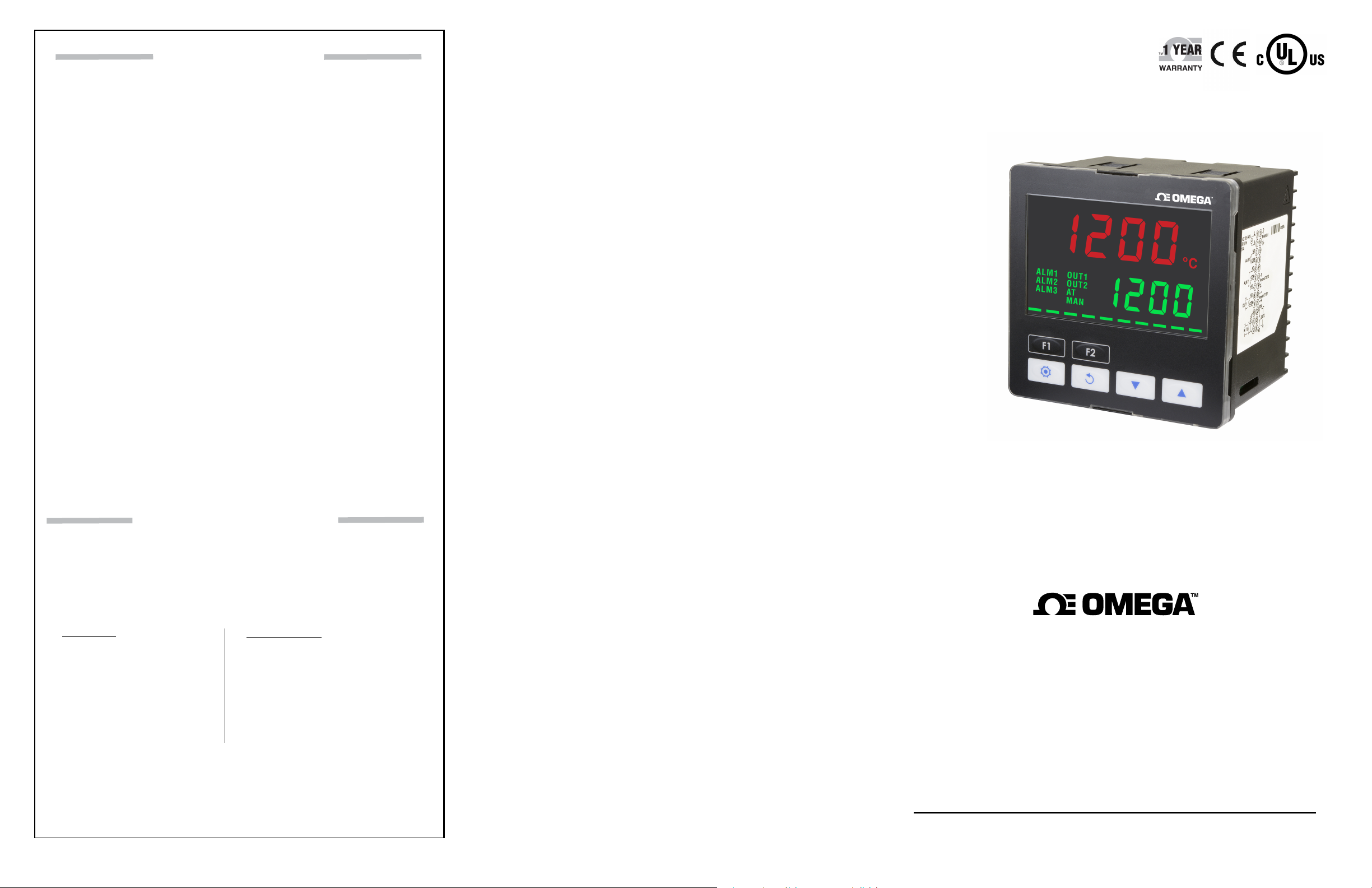
CND3 Series
Temperature Controller
omega.com [email protected]
Servicing North America:
U.S.A.
Headquarters:
The information contained in this document is believed to be correct, but
OMEGA accepts no liability for any errors it contains, and reserves the right to
alter specifications without notice.
Omega Engineering, Inc.
800 Connecticut Ave, Suite 5N01, Norwalk, CT 06854
Toll-Free: 1-800-826-6342 (USA & Canada only)
Customer Service: 1-800-622-2378 (USA & Canada only)
Engineering Service: 1-800-872-9436 (USA & Canada only)
Tel: (203) 359-1660 Fax: (203) 359-7700
e-mail: [email protected]
For Other Locations Visit omega.com/worldwide
Page 2
START HERE
CND3 Series Temperature Controller
Warning
DANGER! Caution! Electric Shock! When the power is on, DO NOT touch the AC terminals in case
an electric shock may occur. Make sure the power is disconnected when you check the input power
supply.
1. Prevent dust or metallic debris from falling into the controller and cause malfunctions. DO NOT modify or uninstall
the controller.
2. CND3 controller is an open-type device. Make sure it is installed in an enclosure free of dust and humidity in case of
an electric shock.
3. Wait for one minute after the power is switched off to allow the capacitor to discharge. DO NOT touch the internal
wiring within this period of time.
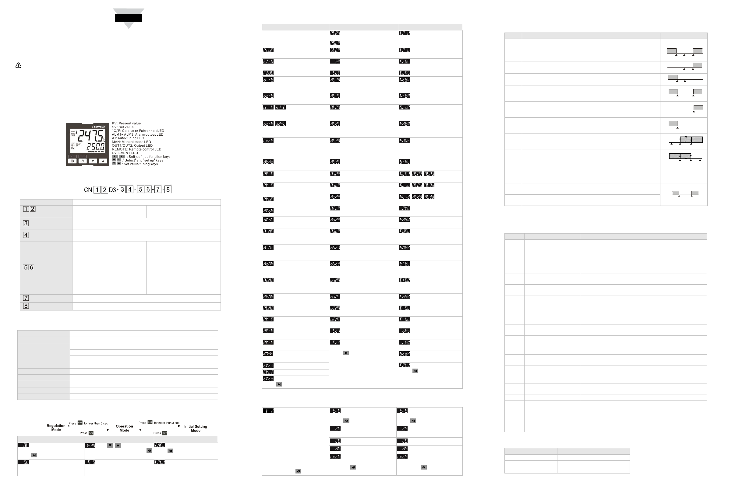
Display, LED & Keys
Ordering Information
Series Omega CND3 series temperature controller
04: 1/4 DIN
Panel size
Output 1
Output 2
08: 1/8 DIN
R: Relay M: Linear mA
S: Voltage Pulse L: Linear voltage
R: Relay M: Linear mA blank: none
S: Voltage Pulse L: Linear voltage
1U: 1 User input
2U: 2 User inputs
1C: 1 CT input
Option 1
2C: 2 CT inputs
RT: Retransmission output
RS: Remote Setup Input
UC: User input + CT input
Option 2
Power
CM: RS-485 Communication blank: none
AC: AC 100 to 240V DC: DC 24V
Specifications
Input power supply AC 100 to 240 V, 50/60Hz, DC 24 V ±10%
Display method LCD. Present temperature: yellow, Set temperature: green
Thermocouple: K, J, T, E, N, R, S, B, L, U, TXK
Input sensors
Platinum RTD: Pt100, JPt100
Resistance: Cu50, Ni120
Analog input: 0 to 5 V, 0 to 10 V, 0 to 20 mA, 4 to 20 mA, 0 to 50 mV
Control modes PID, PID programmable, Fuzzy, Self-tuning, manual, ON/OFF
Display accuracy 0 or 1 digit to the right of the decimal point
Sampling rate Analog input: 0.1s, Thermocouple or platinum RTD: 0.1s
Ambient temperature 0 to +50°C
Ambient humidity 35 to 80% RH (non-condensing)
Parameters Operation
Regulation Mode Operation Mode Initial Setting Mode
Auto-tuning (Set in PID
control and RUN mode)
Press
Self-tuning switch (set
when in PID control and the
TUNE parameter = ST)
Use to set up target
temperature Press
Control loop RUN or
STOP
16: 1/16 DIN
RR: Retrainsmission + Remote
Setup input
UR: User input + Retransmission
output
US: User input + Remote Setup
input
CR: CT input + Retrainsmission
output
CS: CT input + Remote Setup input
blank: none
Set up input type
Press
Set up temperature unit
(not displayed when in analog
input)
Regulation Mode Operation Mode Initial Setting Mode
Select the nth (n = 0 ~ 5)
PID. When n = AUTO, PID is
auto-selected.
Set up PID control offset
Set up Fuzzy gain value
Set up start pattern (when in
PID programmable control and
)
Set up start step (when in
programmable control)
Set up the position of
decimal point
Set up upper temperature
limit
Set up lower temperature
limit
Select control modes
Set up Fuzzy Deadband Lock the keys Select SV control modes
Adjust Output 1 hysteresis
(when in ON/OFF control)
Set up upper limit of Alarm 1
Set up waiting
temperature (when in
programmable control)
Adjust Output 2 hysteresis
(when in ON/OFF control)
Control cycle for
Output 1 (except in ON/OFF
Set up lower limit of Alarm 1
Set up upper limit of Alarm 2
Set up waiting time (when
in programmable control)
Set up start slope (when
in programmable control)
control)
Output 2
Control cycle for
Set up lower limit of Alarm 2 Select pattern to be edited
(except in ON/OFF control)
Ratio of Output 1 against
Set up upper limit of Alarm 3 Select AT or ST
Output 2 when in dual output
control (set when in PID and dual
output control)
Set up deadband
(when in dual output)
Set up input filter factor
Set up input filter range
Adjust input compensation
Adjust input gain
Set up rising slope (when
CRTS = SLOP)
Adjust upper limit
compensation for analog Output
Set up lower limit of Alarm 3
Record highest
temperature of Alarm 1
Record lowest
temperature of Alarm 1
Record highest
temperature of Alarm 2
Record lowest
temperature of Alarm 2
Record highest
temperature of Alarm 3
Record lowest
temperature of Alarm 3
Select heating, cooling or
dual output heating and cooling
Set up Alarm
1 mode
Set up Alarm
1 options
Set up Alarm
1 delay
PV color change
2PID Switch temperature
2PID Reset temperature
1*
Adjust lower limit
compensation for analog Output
Display and adjust Output 1
volume
Set up Remote type
1*
Adjust upper limit
compensation for analog Output
Display and adjust Output 2
volume
Select auxiliary function 1
2*
Adjust lower limit
compensation for analog Output
Set up percentage of upper
limit for Output 1
Select auxiliary function 2
2*
Adjust upper limit
compensation for Retransmission*
Adjust lower limit
compensation for Retransmission*
Adjust Remote gain
Adjust Remote
compensation
Remote lower limit
adjustment
Remote higher limit
adjustment
Set up EVENT1 function
Set up EVENT2 function
Set up EVENT3 function
Set up percentage of lower
limit for Output 1
Set up percentage of upper
limit for Output 2
Set up percentage of lower
limit for Output 2
Display current measured at
CT1
Display current measured at
CT2
Press to return to set up
target
temperature
Enable/disable
communication write-in
Select ASCII or RTU
format
Set up communication
address
Set up baudrate
Set up data length
Set up stop bit
Set up parity bit
Press to return to set up
input type
Press to return to auto-tuning
*1 scale = 2μA; 1scale = 1mV
PID mode: Any of the 6 PID groups can be selected. When n = AUTO, the program will automatically select
the PID group that is the closest to the target temperature.
Select the nth PID (n = 0 ~
5)
Press 0 ~ 5
Set up the 0th PID
temperature value
Press
Set up the 0th proportional
band value
Set up the 0
Set up the 0
Set up the 0th PID integral
deviation
th
Press to return to PID
PID
th
Ti value Set up the 5th Ti value
th
Td value Set up the 5th Td value
deviation
Set up the 5th PID
temperature value
Press
Set up the 5th proportional
band value
Set up the 5th PID integral
deviation
Press to return to PID
deviation
Alarm Outputs
CND3 offers 3 alarm outputs, and each alarm output has 20 alarm modes to choose from in the initial setting mode.
When the target temperature exceeds or falls below the set point, the alarm output will be enabled.
SV Alarm mode Alarm output operation
0 No alarm
Alarm output will be enabled when the temperature reaches upper or
1
lower limit: The alarm will be enable when the PV exceeds SV + AL-H
or falls below SV – AL-L.
Alarm output will be enabled when the temperature reaches the upper
2
limit: The alarm will be enabled when the PV exceeds SV + AL-H.
Alarm output will be enabled when the temperature reaches the lower
3
limit: The alarm will be enabled when the PV falls below SV – AL-L.
Alarm output will be enabled when the temperature reaches the
4
absolute value of the upper or lower limit: The alarm will be enabled
when the PV exceeds AL-H or falls below AL-L.
Alarm output will be enabled when the temperature reaches the
5
absolute value of the upper limit: The alarm will be enabled when the
PV exceeds AL-H.
Alarm output will be enabled when the temperature reaches the
6
absolute value of the lower limit: The alarm will be enabled when the
PV falls below AL-L.
Upper limit hysteresis alarm: The alarm will be enabled when the PV
7
exceeds SV + AL-H. The alarm will be disabled when the PV falls
below SV + AL-L.
Lower limit hysteresis alarm: The alarm will be enabled when the PV
8
falls below SV – AL-H. The alarm will be disabled when the PV
exceeds SV – AL-L.
Offline alarm: The alarm will be enabled when the input sensor is not
9
correct or offline.
ON
OFF
SV-(AL-L) SV SV+(AL-H)
ON
OFF
ON
OFF
ON
OFF
ON
OFF
ON
OFF
ON
OFF
ON
OFF
SV SV+(AL-H)
SV
SV-(AL-L)
AL-L AL-H
AL-L
SV SV+(AL-L) SV+(AL-H)
SV-(AL-H) SV-(AL-L) SV
AL-H
10 Timing alarm
CT1 alarm: The alarm will be enabled when the CT1 value falls below
11
AL-L or exceeds AL-H.
CT2 alarm: The alarm will be enabled when the CT2 value falls below
12
AL-L or exceeds AL-H.
ON
OFF
AL-L
AL-H
¾ RS485 Communication
CND3 supports baudrate 2,400 to 38,400 bps, Modbus ASCII/RTU protocol, function code 03H and reads
maximum 8 words from the register.
Address Content Definition
Measuring unit: 0.1 scale. The following values read mean
error occurs.
1000H Present value (PV)
8002H: Temperature not yet acquired
8003H: Not connected to sensor
8004H: Incorrect sensor
1001H Set value (SV) Measuring unit: 0.1 scale.
1002H
1003H
Upper limit of temp.
range
Lower limit of temp.
range
Cannot exceed the default value
Cannot fall below the default value
1005H Control mode 0: PID, 1: ON/OFF, 2: Manual, 3: FUZZY
Heating/cooling control 0: Heating/ Heating, 1: Cooling/ Heating, 2: Heating/cooling, 3:
1006H
1st heating/cooling control
1007H
cycle
2nd heating/cooling control
1008H
cycle
Cooling/ Cooling
0.1 ~ 99.0 sec.
0.1 ~ 99.0 sec.
1009H Proportional band (PB) 0.1 ~ 999.9
100AH Ti value 0 ~ 9,999
100BH Td value 0 ~ 9,999
1012H
1013H
Read/write Output 1
volume
Read/write Output 2
volume
Unit: 0.1%, only valid in manual control mode
Unit: 0.1%, only valid in manual control mode
1016H Regulated temp. value -99.9 ~ +99.9, Unit: 0.1
102AH Read/write LED status
b0: ALM3, b1: ALM2, b2: °F, b3: °C, b4: ALM1, b5: OUT2, b6:
OUT1, b7: AT
102BH Read/write key status b0: Set, b1: Select, b2: Up, b3: Down, 0: Press it
102CH Panel lockup status 0: Normal, 1: Fully locked, 2: SV adjustable
102DH CT value Unit: 0.1A
103BH AT setting
103CH Control RUN/STOP
setting
0:OFF(default), 1:ON
0 : STOP, 1:RUN (default), 2 : END (program), 3 : HOLD
(program)
Panel Cutout
Model Panel cutout ( W × H )
1/16 DIN 45mm × 45mm
1/8 DIN 44.5mm × 91.5mm
1/4 DIN 91mm × 91mm
 Loading...