

Page 1

COMMERCIAL IN CONFIDENCE
OMEGA Engineering, Inc.
BD9-PROTOCOL
CN9300/CN9400/CN9500/CN9600
MODBUS RTU PROTOCOL
COMMUNICATIONS GUIDE
ISSUE 1.10
Page 2

COMMERCIAL IN CONFIDENCE
1. DESCRIPTION
This document describes the interaction between Omega Controllers with the BD-C2 or BD-C4
communications option and a PC/PLC attached to the bus and acting in a command mode.
There are fundamental limitations placed on the interactions. These arise from the intrinsic properties
of the controllers, with just three control buttons and a multi-level menu with increment or decrement
value change process.
The standalone controllers currently perform a verification on each change to ensure that illegal values
(e.g. ones outside the limit range for a particular thermocouple, etc.) are not accepted. The PC
application needs to replicate the verification checks that the controllers would perform before
transmitting the new data out over the bus to the instrument. The controllers assume that the values
they receive have been checked against limits and are valid - no further verification is carried out.
Upon receipt of the new values and an exit program mode sequence the controllers write the new
values to memory and then restart.
?Copyright 2001 OMEGA Engineering, Inc. All rights strictly reserved. No part of this documentation
shall be reproduced, stored in a retrieval system, or copied in any form, without prior written permission
from OMEGA Engineering, Inc. Every effort has been taken to ensure the accuracy of this specification
but OMEGA Engineering, Inc accepts no liability for any errors it contains. Due to our policy of
continuous development to improve our products, this could without notice, result in amendments or
omissions to this document. Neither is any liability assumed for damage, injury, loss, or expenses
resulting from the use of this document.
Page 3

COMMERCIAL IN CONFIDENCE
1. MEMORY MAP OF PARAMETERS
WARNING:- As with any computer system writing to any unauthorised memory address will
inevitably cause malfunction and may put the instrument in an indeterminate or dangerous state. It is
the users responsibility to ensure correct use.
The instruments use an 8051 type processor. This has two types of RAM: the internal 256 bytes and
the ‘external’ 256 bytes, data is also stored in EEPROM (non-volatile ram). Each data area requires a
different access method internally.
Data can be accessed as either one byte or a two-byte word - the word need not necessarily lie on an
even address boundary. To simplify ModBus messages the unit decodes the MSB of the ModBus
address to select which type of memory to access - thus all memory looks the same to the end user.
Decoding is as follows:
bit 7 bit 6 bit 5 bit 4 bit 3 bit 2 bit 1 bit 0
always 0 always 0 always 0 1=security always 0 1=NVram 1=external 1=one byte
so that the following addresses specify the given memory areas:
• 00xxH references internal memory - two bytes wide
• 01xxH references internal memory - one byte wide
• 02xxH references external memory - two bytes wide
• 03xxH references external memory - one byte wide
• 04xxH references NV memory - two bytes wide
• 05xxH references NV memory - one byte wide
Note that messages with both bits 1 and 2 set are misleading and should not occur, however, they will
be interpreted as if bit 2 was 0. Bit 4 is used to indicate reserved messages - see the section Security
Messages below.
Two types of bit value may exist:
• those which can be set and cleared as a single operation (i.e. directly addressable) are
defined as type bit.
• those which must be set or cleared by reading a byte, masking the bit, then writing the
byte.
Bit addresses are represented by both the absolute hex address and also by bit number (in decimal) if
the bit is directly addressable. Note that, in this document, the bit number is one based (1..128) which
matches the usual representation of ModBus.
The byte and word addresses given are the absolute HEX locations in the instrument.
Depending on the type of ModBus driver being used, these may need to be converted to a
decimal address, plus 1, since some ModBus drivers subtract 1 from the address given. Thus to
access the Baud Rate (03D6) a ModBus driver would need decimal address 983 (982 + 1).
Shaded sections denote contiguous address space which may be read and written as multiple
registers if the remote software can handle this. NOTE that due to space limitations the current
implementation does not allow multiple address access - only one word can be accessed per
message.
To facilitate easy reading, the following tables are listed in address order, not the order on the menus.
Extreme care must be taken to write only to those locations indicated. Writing to any other
locations WILL corrupt the instrument, but the effects may not necessarily be immediately
noticed.
Page 4
COMMERCIAL IN CONFIDENCE
1.1 Internal data formats
The instrument stores data in a variety of ways to allow a full range of values to be held in the
minimum space possible. Most are represented by a multiple of the displayed value - this is given as a
scale factor in the table below: for instance, temperatures are stored in 10ths of a degree, so a
displayed value of 123.4 degrees is stored as 1234 - this is shown in the tables as temp * 10. Some
time values are stored in 40ms units so a time of 1 second would be stored as 25. A few parameters mainly the times - have different scale factors and offsets depending on their current value - these are
detailed individually.
Parameters are incremented/decremented by fixed step sizes depending on their current value within
limits which may change depending on the current value of other parameters. Many parameters
increment and decrement in the same manner - this is referred to in the tables as normal inc/dec - in
these cases parameters move in 0.1 steps between –9.9 and 9.9, otherwise in steps of 1. Note that
when incrementing or decrementing, the internal storage format must be taken into account and also
whether the display is in hi-res mode - values sent to the instrument must match the current mode.
Note also that in the CN9600 instrument parameters marked with [LIN] are stored in degrees*10 when
the selected input is a thermocouple or RTD and units of 1 when the selected input is linear. Also note
that while linear input is selected the display of values on the instrument is effected by the setting in
DECP not Disp.
The instrument provides no error checking on values transmitted to it - the user must ensure that new
values are checked for consistency before uploading.
1.2 Variables not on menu structure
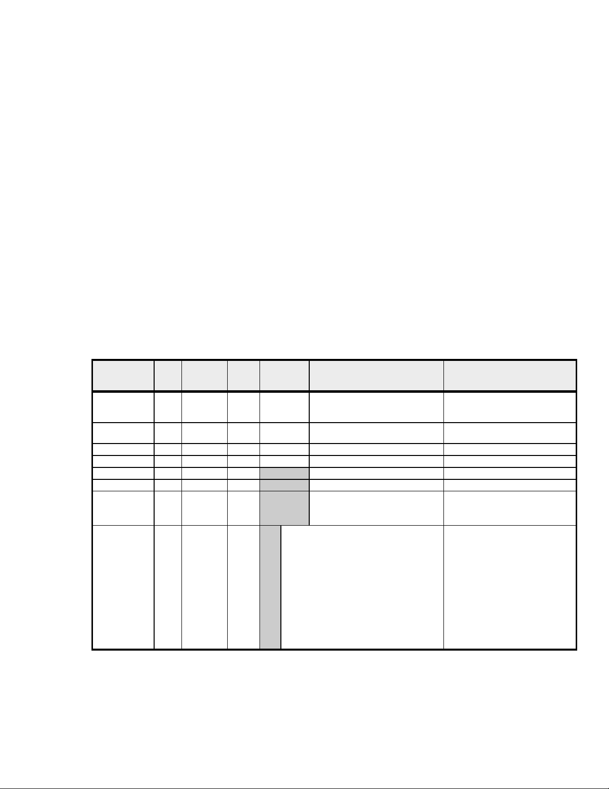
Parameter
Name
SP1 2 007F RW 3/6 Degrees * 10 [LIN]
Setpoint
safety check
Temperature 2 001C R 3/6 Degrees * 10 [LIN] stored as 10ths of deg C
security byte 1 0300 W 6 no scaling see 2.3 for security messages
Ramp Byte 1 0305 R 3 no scaling see 1.2.2 below for bit meanings
Display Byte 1 0306 R 3 no scaling see 1.2.3 below for interpretation
Display State 2 0205 R 3 no scaling a word read enables Ramp byte
Model
(Type of inst
and output
configuration)
Size Address
(hex)
1 0125 RW 3/6 see note 1.2.1 below for correct
2 04FC R 3 0X01 CN9512/9312 RLY/dc Pulse
R/W Modbus
Function
read/write
0X02 CN9522/9322 dc Pulse/dc Pulse
0X03 CN9511/9311 RLY/RLY
0X07 CN9412 RLY/dc Pulse
0X08 CN9422 dc Pulse/dc Pulse
0X09 CN9411 RLY / RLY
0x10 CN96211 dc Pulse/RLY/RLY
0x11 CN96221 dc Pulse/dc Pulse/RLY
0x12 CN96111 RLY/RLY/RLY
0x13 CN96(*)11 ANLG/RLY/RLY
0x14 CN96(*)21 ANLG/dc Pulse/RLY
Internal Storage, Step rate in
Internal units
step 1 from LoSc to HiSc
Comments
The setpoint required. See 1.2.1
below regarding initialising a new
instrument
usage of this byte
and Display Byte to be read with a
single message
Type of instrument and output
configuration are determined by
the hardware, but can be read
from the address 04FC
(*)Analog options: 4 = 4-20mA, 5 = 0–5V, 6 = 0–10V
The Ramp and Display bytes have been kept together so that a single word read at address 0x0205
can be used to obtain full information about the state of the instrument display.
Page 5

COMMERCIAL IN CONFIDENCE
1.2.1 Initialising the Setpoint
The instrument is provided with a safety lock to prevent it from controlling until the setpoint has been
set. This lock is automatically released the first time that the setpoint is changed from the instrument
front panel. If it is required to initialise a new instrument (or after the parameters have been reset), this
lock may be released remotely by performing the following sequence:
tempbyte = (read byte at ModBus address 0125 hex)
tempbyte = tempbyte OR 0x02 {i.e. set bit 1}
(write tempbyte back to ModBus address 0125 hex)
Note that this sequence is only required to unlock the instrument from its reset state - it is not
necessary to perform this sequence each time the setpoint is changed. The other bits within this byte
are used internally and must not be modified.
1.2.2 Ramp Byte
The Ramp Byte holds bits which show what stage of a ramp/soak sequence is currently active:
• bit 1 set = in ramp phase, display periodically flashing “SPr”
• bit 2 set = in soak phase, display periodically flashing “Soak”
• bit 3 set = sequence finished, control dormant, display flashes “Stop”
• bit 6 set = Holdback LED on front display lit (CN9600 only)
Note that these bits are mutually exclusive (except the holdback bit), and the flashing display is of
lower priority than the displays recorded by the Display Byte. If no bit is set, the instrument is not in a
ramp/soak sequence. If the unit has finished a ramp but no soak time is specified (SOAK=’- -‘) bit 2
will remain set.
The other bits in the Ramp Byte are used internally by the instrument. The Ramp Byte must not be
written to - unpredictable and possibly dangerous instrument behaviour will result.
1.2.3 Display Byte
The Display Byte records the message currently being shown on the instrument display, and also
mirrors the state of the SP LED’s - note that although these may be read by a remote program, their
values may change rapidly in real time. Due to the time lag in processing communications messages it
may not be possible to exactly mimic the display on a remote screen - particularly for short cycle times.
The hi nibble conveys the following meanings:
• Bit 7 set = SP2 LED lit
• Bit 6 set = SP1 LED lit
• Bit 5 set = add FAIL display to other indications
• Bit 4 set = SP3 LED lit (CN9600 only)
The low nibble of the Display Byte indicates the current alternating message being displayed, thus
after the top 2 bits are masked off, the following values indicate the display message:
0x01 = PARK / temp
0x02 = -AL- / temp
0x03 = TUNE / temp
0x23 = TUNE / FAIL
0x04 = TUNE / ATSP / temp
0x05 = HAND / heat power ratio
0x25 = HAND / FAIL
0x26 = INPT / FAIL
0x27 = DATA / FAIL
These messages take display precedence over any others. If one of the Display Byte messages is
indicated, the remote program must ignore the state of the Ramp Byte.
Page 6

COMMERCIAL IN CONFIDENCE
1.3 Level C - parameters in address order
Parameter
Name
Addr 1 03D5 RW 3/6 0..255 valid range 1..247
Baud 1 03D6 RW 3/6 0=1200, 1=2400, 2=4800, 3=9600,
Data 1 03D7 RW 3/6 0=18n1, 2=18e1, 3=18o1,
Dbg 1 03D8 RW 3/6 0=off, 1=on
Size Address
(hex)
R/W ModBus
Function
read/write
Internal Storage, Step rate in
Internal units
4=19200
Comments
Note that all changes to the communications level parameters take effect immediately on leaving the
menu, or on receipt of the exit program mode command. The dbg feature may be set on or off. When
on, the right-most digit will flash 3 horizontal segments on receipt of a character when a
communications board is fitted, the left-most digit will flash on transmission of a character.
1.4 Level 1 - parameters in address order
Parameter
Name
Set.2 2 0081 RW 3/6 Degrees * 10 [LIN]
Ofst 2 0083 RW 3/6 Degrees * 10 [LIN]
Band 2 0085 RW 3/6 Degrees * 10 [LIN]
Bnd.2 2 0087 RW 3/6 Degrees * 10 [LIN]
Tune 1 0189 RW 3/6 0=off, 1=on, 2=park, 3=at Setpoint
Dac 1 018A RW 3/6 stored as value*2 so 0.5 is stored as 1
Int.t 1 018B RW 3/6 intt * 10 up 10.0, then intt+90
Der.t 1 018C RW 3/6 1 – 200 in 1 sec steps
Cyc.t 1 018D RW 3/6 Cyct * 10 up 10.0, then Cyct+90
Cyc.2 1 018E RW 3/6 Cyc2 * 10 up 10.0, then Cyc2+90
SP.lk bit 0028 RW 1/5 0=off, 1=on
SPrr 2 02D0 RW 3/6 Stored as SPrr
Soak 2 02D2 RW 3/6 0xFF00 = ‘- -‘, 0=off, otherwise Soak * 10
SPrn 1 03D4 RW 3/6 0=off, 1=on, 2=hold CN9600 See Level
Size Address
(hex)
R/W ModBus
Function
read/write
Internal Storage, Step rate in Internal units,
Limits
Step 0.1 or 1 depending on disp selection
min=LoSc, max=HiSc
normal inc/dec
see separate details for limits
normal inc/dec
min=0.1 max=25% of Sensor Maximum
normal inc/dec
see separate details for limits
step by 0.5
Min=0.5 max=5.0
normal inc/dec
0=off min=0.1, max=60
normal inc/dec
0=off min=0.1, max=81
normal inc/dec
0=off min=0.1, max=81
if <100 step by 1, if <1000 step by 5 else step by
10
min=0 max=9990
Step by 1 up to 120, then 5 up to 300 then by 10
min = 1, max=1440
Comments
CN9600 max is
100% of sensor
maximum
CN9600 display
effected by DECP
when LIN input
selected
P section for notes
on starting a
program
Page 7

COMMERCIAL IN CONFIDENCE
1.5 Level 2 - parameters in address order
Parameter
Name
SP1.P
SP1_ontime
SP1_proptime22
Disp bit 002A RW 1/5 0=low res, 1= high res
Hand 1 018F RW 3/6 No scaling
PL.1 1 0190 RW 3/6 No scaling
PL.2 1 0191 RW 3/6 No scaling
SP2.A 1 0192 RW 3/6 0=none, 1=dvhi, 2=dvlo, 3=band,
SP2.b 1 0193 RW 3/6 0=none, 1=ltch, 2=hold, 3=ltho,
Hi.SC 2 0094 RW 3/6 HiSc * 10 [LIN]
Lo.SC 2 0096 RW 3/6 LoSc * 10 [LIN]
Inpt 1 0198 RW 3/6 0=none, 1=Tcb, 2=Tce, 3=Tcj,
Unit 1 0199 RW 3/6 0=none, 1=C, 2=F, 3=bar, 4=PSI,
Size Address
(hex)
0062
0078
R/W ModBus
Function
read/write
R
3
R
3
Internal Storage, Step rate in
Internal units, Limits
not stored must be computed as
step by 1
min 0=off, max=100
step by 1
min=0, max=100
step by 1
min=0, max=100
4=fshi, 5=fslo, 6=cool
4=nlin
step by 0.1 or 1
min=Sensor Min, max=Sensor Max
step by 0.1 or 1
min=Sensor Min, max=Sensor Max
4=Tck, 5=Tcl, 6= Tcn, 7=TcR,
8=Tcs, 9=Tct, 10=RTD, 11=lin1
12=lin2, 13=lin3, 14=lin4, 15=lin5
5=Ph, 6=Rh, 7=set
Comments
SP1_ontime/SP1_proptime
*100%
CN9600 7=EOP
CN9600
11=lin
12-15 unused
Page 8
COMMERCIAL IN CONFIDENCE
1.6 Level 3 - parameters in address order
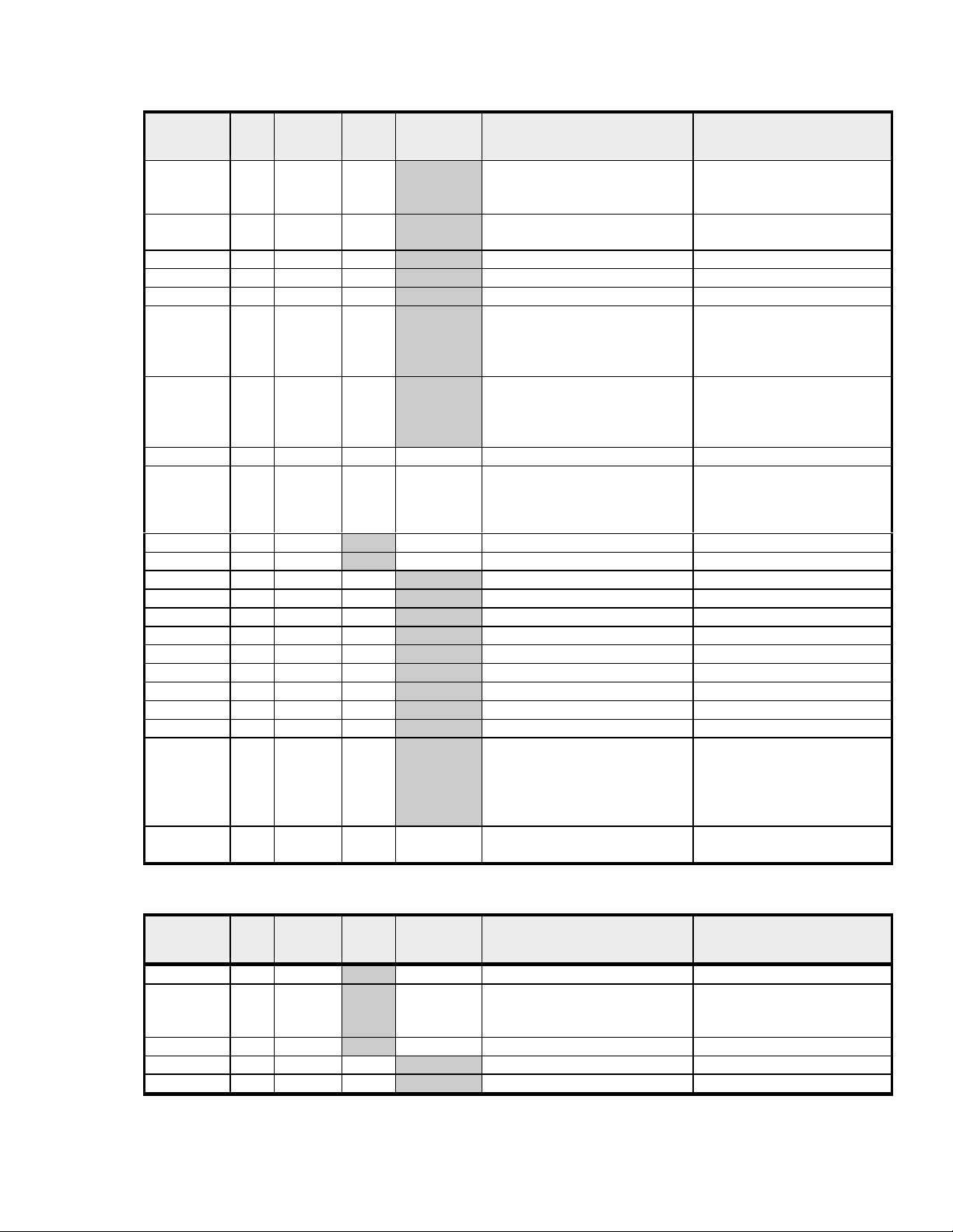
Parameter
Name
SP1.d 1 019D R 3/6 0=none, 1=rly, 2=ssd, 3=rly1,
SP2.d N/A N/A N/A N/A Not stored Inverse of SP1.d
Burn 1 019E RW 3/6 0=upsc, 1=dnsc, 2=1u2d, 3=1d2u
Rev.d 1 019F RW 3/6 0=1r2d, 1=1d2d, 2=1r2r, 3=1d2r
Rev.l 1 01A0 RW 3/6 0=1n2n, 2=1l2n, 3=1n2l, 4=1l2l
Span 2 00A1 RW 3/6 Span * 10 [LIN]
Zero 2 00A3 RW 3/6 Zero * 10 [LIN]
Chek bit 0026 RW 1/5 0=off, 1=on
Read (var) 2 computed from 2 vars (below)
Read (hi) 2 007A R 3 Read(hi) * 10 [LIN]
Read (lo) 2 007C R 3 Read(lo) * 10 [LIN]
Data (Ct A) 2 0432 R 3 CtA * 25
Data (Ct B) 2 0434 R 3 CtB * 25
Data (Ct 1) 2 0436 R 3 Ct1 * 25
Data (Ct 2) 2 0438 R 3 Ct2 * 25
Data (Ct 3) 2 043A R 3 Ct3 * 25
Data (Ct 4) 2 043C R 3 Ct4 * 25
Data (Os 1) 2 043E R 3 Os1 * 10 [LIN]
Data (us) 2 0440 R 3 Us * 10 [LIN]
Data (Os 2) 2 0442 R 3 Os2 * 10 [LIN]
Ver
(S/W ver)
Rset bit 0027 RW 1/5 0=none, 1=all
Size Address
(hex)
2 04FD R 3 0xFFFF/ 0x01 means ver 391
R/W ModBus
Function
read/write
Internal Storage, Step rate in
Internal units, Limits
4=rly2
5=ssd1(ssd2)
normal inc/dec
min = -0.25 * Sensor Min
max = 0.25 * Sensor Max
normal inc/dec
min = -0.25 * Sensor Min
max = 0.25 * Sensor Max
0x02 means ver 392
0x03 means ver 941
0x04 means ver 951
0X05 means ver 952
Comments
CN9600
0=none 1,3,4,10=ssd
2,5,6,8=rly 7,9=anlg
Read(hi) - Read(lo) with
degC to decF if required (if
unit=1)
CN9300/CN9500 ver 1
CN9300/CN9500 ver2
CN9400 ver 1
CN9600 ver 1
CN9600 ver 2
1.7 Level 4 - parameters in address order
Parameter
Name
Der.S 1 019A RW 3/6 Ders * 10
Dis.S 1 019B RW 3/6 0=dir, then 1..32
Lock 1 019C RW 3/6 0 = none, 1=lev3, 2=lev2, 3=all
Prog bit 002D 1/5 0 = auto, 1=stay
No.Al bit 002E RW 1/5 0 = off, 1=on
Size Address
(hex)
R/W ModBus
Function
read/write
Internal Storage, Step rate in
Internal units, Limits
step by 1
min=0, max=32
Comments
Page 9
COMMERCIAL IN CONFIDENCE
1.8 Level A – parameters in address order (CN9600 only)
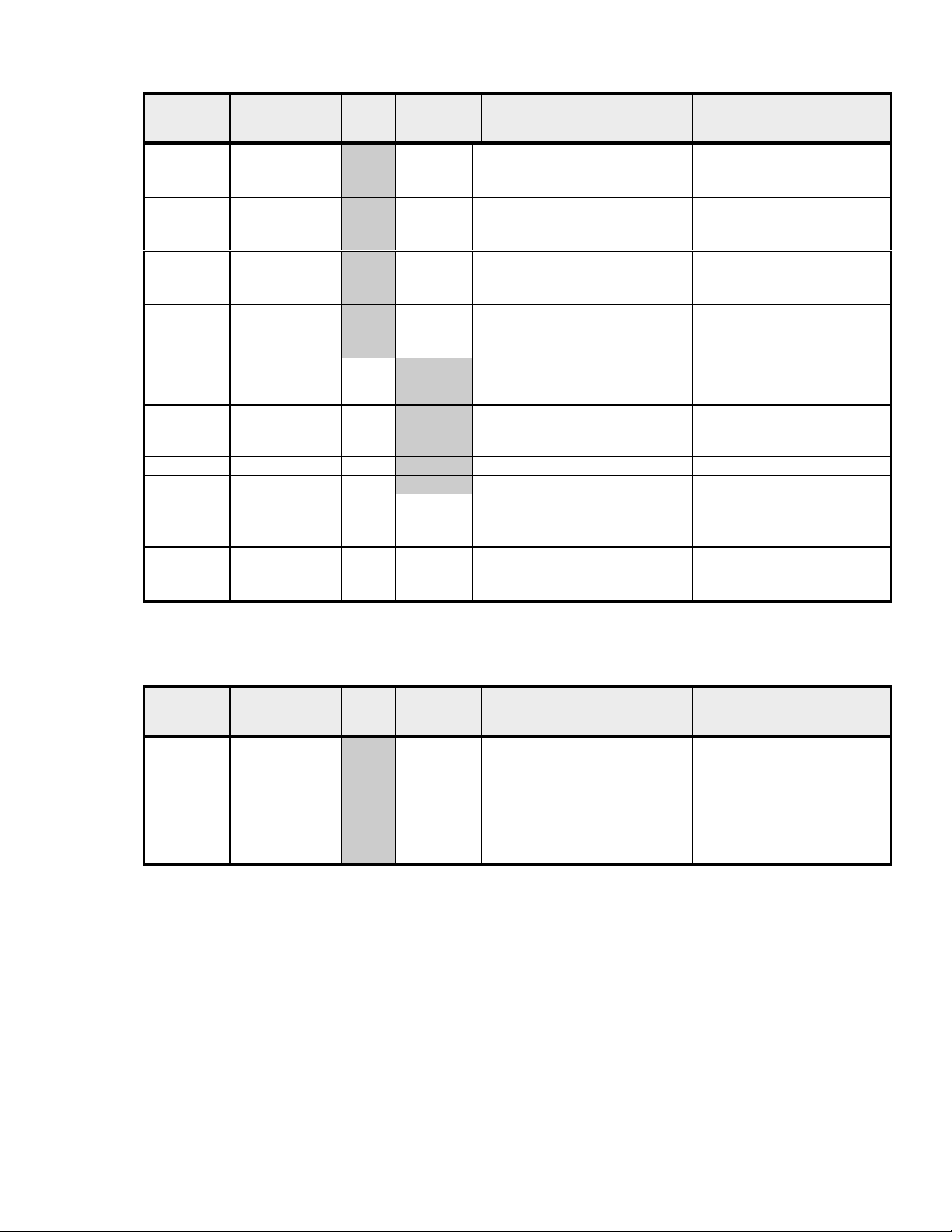
Parameter
Name
An.Hi 2 02D9 RW 3/6 AnHi
An.Lo 2 02DB RW 3/6 AnLo
Hi.In 2 02DD RW 3/6 HiIn * 10
Lo.In 2 02DF RW 3/6 LoIn * 10
DECP 1 03E1 RW 3/6 0=0000, 1=000.0, 2=00.00 Decp over-rides the Disp setting
SP3.A 1 03E2 RW 3/6 0=none, 1=dvhi, 2=dvlo, 3=band,
SP3.B 1 03E3 RW 3/6 0=none, 1=ltch, 2=hold, 3=ltho
Brn.3 1 03E4 RW 3/6 0=upsc, 1=dnsc
Rev.3 1 03E5 RW 3/6 0=3d, 1=3r
Set.3 2 02E8 RW 3/6 Degrees * 10 [LIN]
Hys.3 2 02EA RW 3/6 Hys3 * 10 [LIN]
Size Address
(hex)
R/W ModBus
Function
read/write
Internal Storage, Step rate in
Internal units, Limits
Step=1
min=-1999, max=9999
Step=1
min=-1999, max=9999
step=0.1
min=0.1, max 50.0
step=0.1
min=0.0, max 49.9
4=fshi, 5=fslo
step=0.1
min=0.0, max=2500
step=0.1
min=0.1, max=100% of HiSc
Comments
HiIn must always be 0.1 above
the LoIn setting
in level 2 while linear input
selected
CN9600 7=EOP
When LIN sensor selected
max=9999
Note: The level A menu is only available in the CN9600 instrument.
1.9 Level P – parameters in address order (CN9600 only)
Parameter
Name
MaxProg 1 033A R 3 Maximum Program Number Generated by the instrument, do
Prog 1 036C RW 3/6 Program Number
Note: The level P menu is only available in the CN9600 instrument.
Note: The other elements of the programmer (Level P) menu are unavailable from the communications
interface.
Size Address
(hex)
R/W ModBus
Function
read/write
Internal Storage, Step rate in
Internal units, Limits
min=1, max=MaxProg
Comments
not write to this location.
To start a program write the
number of the program to run
and then set the value of
Sprn(Level 1) to ON or HOLD
Note: the program will not start
until after the exit program mode
Page 10

COMMERCIAL IN CONFIDENCE
2. ACTIONS REQUIRED TO COMMUNICATE WITH THE
INSTRUMENTS
These versions of the instruments have ModBus functions codes 1,3,5,6 and 16 implemented. Note
that although function code 16 (write multiple registers) is recognised, this cannot deal with more than
a single 2 byte register write and will return an error if more registers are attempted. There is no facility
to read multiple registers, nor to read or write multiple bits.
2.1 Notes
• Un-implemented function codes do not yet return error code 01.
• Function code 15 (read multiple registers) is not implemented.
2.2 Implementation restrictions
A number of restrictions are made :
• Multiple register reads are not implemented, since the opportunity to use them is very
limited and there is not sufficient memory to buffer long messages.
• Multiple bit reads and writes are not implemented, since we do not have any consecutive
bits available to the user.
2.3 Security Messages
To allow communications to safely manipulate the instrument a number of security messages
have been implemented. OMEGA Engineering, Inc see these as important safety features,
which offer a number of advantages, especially when configuring a safety critical application.
The messages to enter program mode only have to be sent once to access the Internal
parameters of the instrument and then any number of adjustments can be made. The advantage
this offers is that sending the enter program mode message, causes the push buttons on the
instrument to be locked out. This feature prevents potentially dangerous conditions arising
from simultaneous adjustment of the instrument locally whilst adjustments are being sent over
the communications link.
The messages to exit program mode causes the instrument to write back any internal
parameter changes to the NVram, and then use these settings. This means that any changes
made will not take effect until the instrument has received the exit program mode message. The
advantage this offers is that all adjustments take place at the same time. If for instance you are
configuring alarm functions you will not get false alarms due to setting the alarm mode before a
valid alarm set point has been programmed, also all PID terms are implemented together,
whereas separate adjustment of PID functions may cause greater control instability.
To prevent inadvertent changes a security byte must be set immediately before any security message
is transmitted - this byte is automatically reset after each message.
Each security message is numbered 1 to 6, this number must be set into the security byte immediately
prior to the message, if the security byte does not match the security message number, the message
will be ignored and no response will be issued. Messages 1 to 4 are implemented but currently have
no direct use.
Note: The CN9600 does not require the security byte messages to be sent to enter and exit
program mode, the messages not required are noted below.
The correct sequence to set new parameters into the instrument is as follows:
Page 11

COMMERCIAL IN CONFIDENCE
1. Write the security byte with value 5 (CN9600 – Not Required)
2. Send message number 5 (enter program mode)
3. Send messages as required to change desired parameters
4. Write the security byte with value 6 (CN9600 – Not Required)
5. Send message number 6 (exit program mode)
It is possible to write to parameters without using this sequence, but the unit will simply
hold new values in the menu structure, and will not apply the new values to the
process control variables. However, if new parameters are uploaded and then the
menu entered from the front panel, any uploaded parameters will be effective on
leaving the menu. When using communications the enter program mode / exit
program mode message sequence must be sent to cause any new values to be
applied to the controller.
2.3.1 Enter Program Mode
Byte No Meaning Value
1 Slave address xx
2 ModBus Function code (write register) 06
3 Security message function marker (1=security, 5=function 5) 15
4 not used (any value may be sent) xx
5 not used (any value may be sent) xx
6 not used (any value may be sent) xx
7 CRC lo byte ??
8 CRC hi byte ??
The security byte must be set to 5 prior to this message (not required for CN9600). If
the instrument is successfully set into remote program mode, and the keyboard is
successfully locked, the response will be the same as the message. If the instrument
is currently in manual menu entry mode, an error response code 6 (device busy) will
be returned. This command may be repeated while already in remote program mode
with no ill effect.
2.3.2 Exit Program Mode
Byte No Meaning Value
1 Slave address xx
2 ModBus Function code (write register) 06
3 Security message function marker (1=security, 6=function 6) 16
4 not used (any value may be sent) xx
5 not used (any value may be sent) xx
6 not used (any value may be sent) xx
7 CRC lo byte ??
8 CRC hi byte ??
The security byte must be set to 6 prior to this message (not required for CN9600). The response will
be the same as the message if the instrument is currently in remote program mode, and a restart will
be initiated, otherwise an error response code 1 (illegal function) will be returned.
Page 12

COMMERCIAL IN CONFIDENCE
2.4 ModBus Message Construction.
The following message function codes are implemented in the instrument. Where a value of xx is
shown, substitute the correct value for your installation and the data item required. All CRCs are shown
as ?? since must be automatically generated according to the data contained in the message.
2.4.1 Read Coil Status (single bit read)
Byte No Meaning Value (hex)
1 Slave address xx
2 ModBus Function code (read coil status) 01
3 Starting Address MSB, always 00
4 Starting Address LSB xx
5 No of points MSB 00
6 No of points LSB 01
7 CRC lo byte ??
8 CRC hi byte ??
Note that in this implementation, only one bit may be read per message, so the number of
points should always be set to 1, but in fact this value is ignored anyway. If the address is not a
valid readable bit, an error response code 2 (invalid address) is returned, otherwise the
following response is sent:
Byte No Meaning Value (hex)
1 Slave address xx
2 ModBus Function code (read coil status) 01
3 Byte count 01
4 Bit value (01 if bit is set, 00 if not) 00 or 01
5 CRC lo byte ??
6 CRC hi byte ??
2.4.2 Read Holding Registers
Byte No Meaning Value (hex)
1 Slave address xx
2 ModBus Function code (read holding register) 03
3 Starting Address MSB xx
4 Starting Address LSB xx
5 No of registers MSB 00
6 No of registers LSB 01
7 CRC lo byte ??
8 CRC hi byte ??
Note that the only one register may be read per message, so the number of registers should be 1
(although this value is ignored in this implementation). The normal response will be:
Byte No Meaning Value (hex)
1 Slave address xx
2 ModBus Function code (read register) 03
3 Byte count (always 2, even though the register may be only 1
byte wide)
4 Data MSB (will be 0 if a single byte register) xx
5 Data LSB xx
6 CRC lo byte ??
7 CRC hi byte ??
02
Page 13

COMMERCIAL IN CONFIDENCE
2.4.3 Force Single Coil (write single bit)
Byte No Meaning Value (hex)
1 Slave address xx
2 ModBus Function code (force coil) 05
3 Starting Address MSB, always 00, all bits are in internal
memory
4 Starting Address LSB xx
5 Force Data MSB (FF sets the bit, 00 clears it) FF or 00
6 Force Data LSB (always 00) 00
7 CRC lo byte ??
8 CRC hi byte ??
00
An error response code 2 (illegal address) will be returned if the bit is not a valid writeable bit,
otherwise the response is the same as the above message.
2.4.4 Preset Single Register
Byte No Meaning Value (hex)
1 Slave address xx
2 ModBus Function code (write register) 06
3 Starting Address MSB xx
4 Starting Address LSB xx
5 Data MSB xx
6 Data LSB xx
7 CRC lo byte ??
8 CRC hi byte ??
The normal response is the same as the message. An error response code 2 (illegal address)
will be returned if the address is not within the processor bounds.
2.4.5 Preset Multiple Registers
Byte No Meaning Value (hex)
1 Slave address xx
2 ModBus Function code (write register) 10
3 Starting Address MSB xx
4 Starting Address LSB xx
5 Number of registers MSB 00
6 Number of registers LSB 01
7 Number of bytes to follow 02
8 Data MSB xx
9 Data LSB xx
10 CRC lo byte ??
11 CRC hi byte ??
note that this function is a subset of the normal ModBus function code 16 in that only one register of up
to 2 bytes may be written. Thus byte numbers 5, 6 and 7 must be as shown, otherwise an error
response with error code 1 (illegal request) will be returned.
Page 14

COMMERCIAL IN CONFIDENCE
2.5 Exception Code Responses
There are 5 possible responses to received messages:
2.5.1.1 Broadcast message
There is never any response to a broadcast message (one with slave address 0). The
message will be acted on if possible, any errors will go unreported.
2.5.1.2 Slave receives incomplete or corrupt message
No response is returned.
2.5.1.3 Slave receives full message but CRC is incorrect
No response is returned
2.5.1.4 Slave receives message correctly, and acts on it correctly
The normal response as detailed under each message heading is returned.
2.5.1.5 Slave receives full message correctly, but cannot act on it
An error response, as detailed under each message heading, is returned as follows
Byte No Meaning Value
1 Slave address xx
2 Original ModBus Function code but with top bit set 8x
3 Error code xx
4 CRC lo byte ??
5 CRC hi byte ??
The following error codes are implemented :
• 01 - illegal function - not fully implemented in these versions except for
exit program mode when not in program mode, and for function code 16.
In future releases will be returned on receipt of any function code not
implemented.
• 02 - illegal data address
• 04 - slave device failure - not currently implemented in these versions ,
but will be returned if the NVram causes problems when reading or writing
• 06 - slave busy - returned if the keyboard is in use when an enter
program mode request is received.
Page 15

COMMERCIAL IN CONFIDENCE
2.6 CRC calculation
NOTE that the CRC algorithm published in the Modicon ModBus Protocol Guide (PI-MBUS-300
Rev G, Nov 1994) IS WRONG!!!! However, the quick C program using the lookup tables is correct.
The correct algorithm is given here
1. Load a 16 bit register with FFFF (all 1’s). Call this the CRC register.
2. Exclusive OR the first 8 bit byte of the message with the low-order byte of the 16 bit CRC
register, putting the result back into the CRC register
3. Look at the Least Significant Bit of the CRC register and remember it. Call it the LastBit
4. Shift the CRC register one bit right, putting 0 in the top bit
5. If the LastBit was 1, Exclusive OR the CRC register with value A001h (1010 0000 0000
0001)
6. Repeat steps 3,4,5 until 8 shifts have been performed
7. Repeat from step 2 for the next byte of the message until all bytes have been processed
8. The final contents of the CRC register is the CRC value to use
9. When the CRC is placed in the message, the Least Significant Byte is sent first, then the
Most Significant Byte
2.6.1 CRC calculation in C code
There are two ways to implement the CRC, one uses the above algorithm, the other uses precomputed lookup tables which make for a faster calculation. This is given correctly in the ModBus
guide, and can be downloaded from the Internet (search for ModBus and CRC and Generation) and is
not repeated here. The long winded way is as follows (where mess[] holds the message):
unsigned short crc;
unsigned short thisbyte;
unsigned short shift;
unsigned char highbyte, lowbyte;
unsigned char lastbit, i;
crc=0xffff;
for (i=0; i<len(mess); i++)
{
thisbyte= mess[i];
crc = crc^thisbyte;
for (shift=1; shift<=8; shift++)
{
lastbit = crc & 1;
crc = (crc >> 1) & 0x7fff;
if (lastbit==1)
{
crc = crc^0xA001 ;
}
}
}
highbyte=(crc>>8)&0xff;
lowbyte=crc&0xff;
Page 16

COMMERCIAL IN CONFIDENCE
Reading the Controllers Setpoint
An 8 byte message must be transmitted to the Controller as follows:
byte 0 : Slave address xx
byte 1 : Read Register Function code 03 hex
byte 2 : High Byte of Register address 00 hex
byte 3 : Low byte of Register address 7F hex
byte 4 : Number of Registers to read (high byte) 00 hex
byte 5 : Number of Registers to read (low byte) 01 hex
byte 6 : CRC lo byte xx
byte 7 : CRC hi byte xx
Note that the CRC must be transmitted with the lo byte first. Bytes must be transmitted in a single
burst, without gaps between each byte - any gap of longer than 1.5 times a character width will cause
the Controller to ignore the message.
The following example shows how to construct a message to read the setpoint, the various sections of
this code would normally be held in separate functions, and would be optimised for better speed, but
this example shows the thought process involved (note also that C uses zero based arrays):
unsigned char mess[8], reply[8];
void BuildMessageToReadSetPoint()
{ unsigned char highbyte,lowbyte;
unsigned short crc,thisbyte,i,shift,lastbit; /* 16 bit word values */
mess[0] = 0x01; /* slave address */
mess[1] = 0x03; /* read function */
mess[2] = 0x00; /* address hi byte */
mess[3] = 0x7F; /* address lo byte */
mess[4] = 0x00; /* number of data points hi byte */
mess[5] = 0x01; /* number of data points lo byte */
/* compute the CRC over the first 6 chars of the message */
crc=0xffff;
for (i=0; i<=5; i++)
{ thisbyte = mess[i];
crc = crc ^ thisbyte;
for (shift = 1; shift <= 8; shift++)
{ lastbit = crc & 0x0001;
crc = (crc >> 1) & 0x7fff;
if (lastbit == 0x0001)
{ crc = crc ^ 0xa001 ;
}
}
}
highbyte = (crc >> 8) & 0xff;
lowbyte = crc & 0xff;
mess[6] = lowbyte;
mess[7] = highbyte;
}
the 8 characters in the message can now be transmitted to the communications port.
Page 17

COMMERCIAL IN CONFIDENCE
After a short delay (approx. 10ms), the Controller will respond with a 7 byte reply. Assuming the
Setpoint to be 200 degrees this would be:
byte 0 : Slave address xx
byte 1 : Function code 03 hex
byte 2 : Number of data bytes to follow 02 hex
byte 3 : High byte of Setpoint value 07 hex
byte 4 : Low byte of Setpoint value D0 hex
byte 5 : Low byte of CRC value ?? hex
byte 6 : High byte of CRC value ?? hex
These characters should be stored in a reply array, and the CRC computed (as above) over the first 5
characters and compared with bytes 5 and 6, the reply should be accepted only if they match. If there
are any errors in the transmitted message, the reply will be missing altogether or the reply will be an
error response. Either way, only accept the reply if the Function code is 03 and the CRC is correct.
The Controller stores the Setpoint internally in 10th degree units, so the value can be computed as:
setpoint = ((reply[3] << 8) + reply[4]) / 10 ;
or, in a language other than C:
setpoint = ((reply[3] * 256) + reply[4]) / 10 ;
Reading the temperature
Exactly the same method is used as above, except replace byte 2 and 3 of the message with the
register address of the Temperature thus:
byte 2 : High byte of Temperature address 00 hex
byte 3 : Low byte of Temperature address 1C hex
The temperature will be returned in bytes 3 and 4 of the reply, exactly as the example for Setpoint, and
this must also be divided by 10 to bring it to degrees. Note that the temperature is always returned in
Centigrade, so any Fahrenheit conversion must be made by the PC.
A typical message would be:
[01][03][00][1C][00][01][45][CC]
A typical reply would be:
[01][03][02][00][C4][B9][D7]
which shows the temperature to be 00C4 hex, 196 decimal, which is 19.6 degrees centigrade.
Page 18

COMMERCIAL IN CONFIDENCE
Writing the Setpoint
Writing to the Controller requires a three stage process which prevents simultaneous access from the
front panel. To prevent accidental changes caused by unreliable communications, a sequence of
messages must be sent in strict order.
1. Lock the keypad - a sequence referred to as enter program mode
2. Write new values to the Controller
3. Unlock the keypad and restart with the new values - a sequence referred to as exit program
mode
1. Enter Program Mode
To enter the programming mode of the Controller, two messages must be transmitted - both must be
recognised, in strict sequence, as valid for the operation to be successful. The first message informs
the controller that the next message is a security locking message, if the second message is not
acknowledged correctly, the whole sequence must be re-started from message 1.
1st Message:
byte 0 : Slave address xx
byte 1 : Function code (write register) 06 hex (always)
byte 2 : Register Address high byte 03 hex (always)
byte 3 : Register Address low byte 00 hex (always)
byte 4 : Register Value high byte 00 hex (always)
byte 5 : Register Value low byte 05 hex (always)
byte 6 : CRC low byte ??
byte 7 : CRC high byte ??
The controller should reply with an identical response, if not, this message should be re-
transmitted until the response is correct.
Note: the CN9600 does not require the security message to be sent.
2nd Message:
byte 0 : Slave address xx
byte 1 : Function code (write register) 06 hex (always)
byte 2 : Register Address high byte 15 hex (always)
byte 3 : Register Address low byte 00 hex (always)
byte 4 : Register Value high byte 00 hex (always)
byte 5 : Register Value low byte 00 hex (always)
byte 6 : CRC low byte ??
byte 7 : CRC high byte ??
The Controller should reply with an identical response, if not, the message pair is lost and the
sequence must be repeated from message 1.
Page 19

COMMERCIAL IN CONFIDENCE
2. Write the Setpoint value
The setpoint value must be sent in the same units as are currently displaying on the controller, that is,
in Degrees Fahrenheit, if selected, otherwise in Centigrade. The value to be transmitted must be an
integer number of 10ths of a degree. For example, to transmit a value of 432.1 degrees, the setpoint
register must be set to 4321 (decimal) which is 10E1 (hex). The following message writes the setpoint,
in this example xx would be 10 (hex) and yy would be E1 (hex).
byte 0 : Slave address xx
byte 1 : Function code (write register) 06 hex (always)
byte 2 : Register Address high byte 00 hex (always)
byte 3 : Register Address low byte 7F hex (always)
byte 4 : Setpoint Value high byte xx
byte 5 : Setpoint Value low byte yy
byte 6 : CRC low byte ??
byte 7 : CRC high byte ??
3. Exit program mode
A two part sequence, similar to the enter program mode sequence is required to accept the new values
and unlock the controller keypad. Similarly, both messages must be present in strict sequence for the
values to take effect.
1st Message:
byte 0 : Slave address xx
byte 1 : Function code (write register) 06 hex (always)
byte 2 : Register Address high byte 03 hex (always)
byte 3 : Register Address low byte 00 hex (always)
byte 4 : Register Value high byte 00 hex (always)
byte 5 : Register Value low byte 06 hex (always)
byte 6 : CRC low byte ??
byte 7 : CRC high byte ??
The controller should reply with an identical response, if not, this message should be retransmitted until the response is correct.
Note: the CN9600 does not require the security message to be sent.
2nd Message:
byte 0 : Slave address xx
byte 1 : Function code (write register) 06 hex (always)
byte 2 : Register Address high byte 16 hex (always)
byte 3 : Register Address low byte 00 hex (always)
byte 4 : Register Value high byte 00 hex (always)
byte 5 : Register Value low byte 00 hex (always)
byte 6 : CRC low byte ??
byte 7 : CRC high byte ??
The Controller should reply with an identical response, if not, the message pair is lost and the
exit program mode sequence must be repeated from message 1.
Any changes made will only take effect on receipt of a valid exit program mode sequence - if the
controller is de-powered before this sequence is completed, the previously stored values will be used.
Page 20

COMMERCIAL IN CONFIDENCE
3.0 VALUE / LIMIT CHECKING
The purpose of this section of the document is to lay down the allowable range of adjustment for all
functions addressable over the communications link.
LEVEL C
Function Values / Limits
ADR 1 – 247
BAUD 1200 2400 4800 9600 19200
DATA 18N1 18E1 18O1
DBUG OFF ON
LEVEL 1
Function Values / Limits
TUNE OFF ON PARK AT.SP
BAND 0.1 – 9.9 10 – 25% of the selected sensors full scale, deg C or F
(CN9600 - 100% of the selected sensors full scale, deg C or F)
INT.T OFF 0.1 – 9.9 10 – 60 Minutes
DER.T OFF 1 – 200 Seconds
DAC 0.5 – 5.0 ( In 0.5 steps)
CYC.T A-- ON.OF 0.1 – 9.9 10 – 81 Seconds
OFST Detailed later dependant on other functions.
SP.LK OFF ON
SPRR 0 – 9990 Deg / Hr
SPRN ON OFF HOLD
SOAK -- 0 – 1440 Min
SET.2 Detailed later dependant on other functions.
BND.2 Detailed later dependant on other functions.
CYC.2 ON.OF 0.1 – 9.9 10 – 81 Seconds.
LEVEL 2
Function Values / Limits
SP1.P 0 - 100 % ( Read only )
HAND OFF 1 – 100 %
PL1 100 – 0 %
PL2 100 – 0 %
SP2.A NONE DV.HI DV.LO BAND FS.HI FS.LO COOL E.OP (9500P)
SP2.B NONE LT.CH HOLD LT.HO NLIN
DISP 1 Deg 0.1 Deg
HI.SC Detailed later dependant on other functions.
LO.SC Detailed later dependant on other functions.
INPT NONE B E J K L N R S T RTD LIN1 LIN2 LIN3 LIN4 LIN5
(CN9600 – LIN1-5 replaced by LIN )
UNIT NONE *C *F BAR PSI PH RH SET
LEVEL 3
Function Values / Limits
SP1.D NONE RLY SSD RLY1 RLY2 SSD1
(CN9600 – NONE RLY SSD ANLG depending on hardware present)
SP2.D NONE RLY SSD RLY1 RLY2 SSD2 (CN9600 as above)
BURN UP.SC DN.SC 1U.2D 1D.2U
REV.D 1R.2D 1D.2D 1R.2R 1D.2R
REV.L 1N.2N 1I.2N 1N.2I 1I.2I
SPAN Detailed later dependant on other functions.
ZERO Detailed later dependant on other functions.
READ VAR* HI* LO* ( Read only ).
TECH CTA CTB CT1 CT2 CT3 CT4 OS1 US OS2 (Read only ).
VER 391 392 941 951 952 ( Read only ).
RSET NONE ALL
Page 21

COMMERCIAL IN CONFIDENCE
LEVEL 4
Function Values / Limits
LOCK NONE LEV.3 LEV.2 ALL
PROG AUTO STAY
NO.AL OFF ON
DIS.S DIR 1 - 32
DER.S 0.1 – 1.0
LEVEL A
Function Values / Limits
AN.HI -1999 - 9999
AN.LO -1999 - 9999
HI.IN 0.1 – 50.0
LO.IN 0.0 – 49.9
DECP 0000 000.0 00.00
SP3.A NONE DV.HI DV.LO BAND FS.HI FS.LO E.OP (9500P)
SP3.B NONE LTCH HOLD LT.HO
BRN.3 UPSC DNSC
REV.3 3D 3R
SET.3 Detailed later dependant on other functions.
HYS.3 0.1 – 100 % of HISC
FUNCTIONS DEPENDANT ON OTHER SETTINGS - ADJUSTABLE LIMITS
This section details the valid limits of adjustment for functions that are inter dependant on each other.
Flow diagrams are used to demonstrate the order in which the functions should be checked to obtain
valid limits. Also included in this section are tables of maximum and minimum adjustment limits for
each sensor and the default HI.SC and LO.SC settings.
Note: that the checks for “> INPT = LIN” apply to the CN9600 only.
SP1 > INPT = LIN > HISC > LOSC > SP.LK > DECP
SP1 > INPT = Others > UNIT > DISP > HISC > LOSC > SP.LK
So set point 1 is adjustable between the current high and low scale settings, as long as the setpoint
lock is off.
OFST > INPT = LIN > CYC.T = ON.OF > 0.0 to 25% of sensor full scale > DECP
= 0.1 to 81 > 0.0 to 50% of BAND setting > DECP
= Others > CYC.T = ON.OF > UNIT > DISP > 0.0 to 25% of sensor full scale
= 0.1 to 81 > DISP > 0.0 to 50% of BAND setting
So OFST is adjustable between +/- 0.0 and 50 % of SP1 proportional band setting or +/- 25 % of
sensors full scale max setting ( see tables 1 and 2 for sensor scales ).Resolution of adjustment is
dependant on DISP setting.
SET.2 > INPT = LIN > SP2.A = FSHI FSLO > -1999 to 9999 > DECP
= DVHI BAND > 0 to 2500 > DECP
= DVLO > 0 to –2500 > DECP
= COOL > -1999 to 2500 > DECP
= Others > SP2.A = DVHI BAND > DISP > 0 - 250
= DVLO > DISP > 1 > 0 to -250
> 0.1 > 0 to -199.9
= FSHI FSLO > UNIT > DISP > sensor full scale min to max
= COOL > DISP > 1 > -250 to 250
> 0.1 > -199.9 to 250.0.
If you change SP2.A at any time then the value of SET.2 defaults to zero.
BND.2 > SP2.A = DVHI to FSLO > INPT > UNIT > DISP > 0.1 to sensor full scale.
So BND.2 is adjustable between 0.1 and the selected sensors full scale, except when you select
COOL mode then you have an upper limit of 25% of the selected sensors full scale.
= COOL > INPT > UNIT > DISP > 0.1 to 25% of sensor full scale.
Page 22

COMMERCIAL IN CONFIDENCE
HISC > INPT = LIN > 1 to 9999 > DECP
= Others > UNIT > DISP > sensor full scale min to max
LOSC > INPT = LIN > 0 to 9999 > DECP
= Others > UNIT > DISP > sensor full scale min to max
So the limits of both of these functions is defined by the type of sensor , C or F , and 1* or 0.1*.
Note that the value of LOSC must be below the value of HISC.
SPAN > INPT = LIN > 0 to 2500 > DECP
= Others > UNIT > DISP > +/- 25% of sensor full scale
So this function is adjustable from –25% to +25% of sensor full scale , in what ever units are selected,
adjustment is in 0.1 increments between –9.9 and 9.9 after this it is in 1 degree increments.
ZERO > This function has the same adjustment range as SPAN.
SPRR > INPT = LIN > 0 to 9995 > DECP
= Others > DISP > 0 to 9995
READ > INPT = LIN > value > DECP
= Others > DISP >value
TECH > INPT = LIN > value > DECP
= Others > DISP >value
CN9600 specific functions and values
LOIN > HIIN
The value of LOIN must always be 0.1 less that the value of HIIN
ANLO > -1999 to 9999 > DECP
ANHI > -1999 to 9999 > DECP
HYS.3 > INPT =LIN > HISC > 1 – HISC > DECP
=Others > HISC > UNIT > DISP > 0.1 – HISC
The value of HYS.3 ranges from 0.1 up to HISC
SET.3 > INPT = LIN > SP3.A = FSHI FSLO > -1999 to 9999
= DVHI BAND > 0 to 2500
= DVLO > 0 to -2500
= Others >SP3.A = FSHI FSLO > UNIT > DISP > sensor full scale min to max
= DVHI BAND > 0 to 250.0
= DVLO > DISP > 1 > 0 to -250
> 0.1 > 0 to –199.9
If you change SP3.A at any time then the value of SET.3 defaults to zero.
There are a number of functions which when changed can have an effect on the values of other
functions, the rules relating to these will be covered in this section.
1/ As mentioned earlier changing SP2.A will cause SET.2 to default to zero.
2/ Changing the value of DISP will cause the resolution of SET.2 . HISC . LOSC . and set point 1 to
change, and also values above 1000 will default to 999.9 if selecting hi- resolution.
3/ If you move set point one to a point outside the limits of HISC or LOSC , then set point 1 will default
to the value of the function it is closest to.
4/ If you select a different INPT sensor this will cause the HISC and LOSC values to change to the
default values of the newly selected sensor. Then obviously the new HISC and LOSC values need to
check that set point 1 is still within these limits. For default values of HISC and LOSC see tables 3 / 4.
5/ The UNIT function has a number of options, but *C and *F are the options we need to consider here,
all other options PH ,RH ,PSI, etc. are treated the same as *C. A number of functions change their
values when you change UNIT and it depends which function you’ve changed as to what type of
conversion is performed. The two types of conversion are absolute and relative.
Note that the CN9600 instrument with a linear input selected ignores the setting of the UNIT
function.
Page 23

COMMERCIAL IN CONFIDENCE
The absolute conversion uses the formula TempF abs = 32 +(TempCabs X 1.8 ) for converting *C to *F
And
TempC abs = TempF abs – 32 / 1.8 for converting *F to *C
The relative conversion uses the formula TempF rel =TempC rel X 1.8 for converting *F to *C
And
TempC rel = TempF rel / 1.8 for converting *C to *F
Here is a list of the functions that are effected by a *C to *F conversion, and if a relative or absolute
conversion is needed.
FUNCTION CONVERSION NOTES
Set point 1 Absolute
HISC Absolute
LOSC Absolute
OFST Relative
BAND Relative
BND.2 Relative
ZERO Relative
SPAN Relative
READ Relative
TECH Relative Conversion only performed on
OS1 US OS2
SET.2 Absolute/Relative Absolute – FSHI FSLO
Relative – DVHI DVLO BAND COOL
SET.3 Absolute/Relative Absolute – FSHI FSLO
Relative – DVHI DVLO BAND
HYS.3 Relative
Page 24

COMMERCIAL IN CONFIDENCE
TABLE 1 MIN/MAX SENSOR FULL SCALE DEGREE C
SENSOR
MIN
MAX
MIN 0.1
MAX 0.1
B01800
0.0
999.9
E0600
0.0
600.0
J0800
0.0
800.0
K
- 50
1200
- 50.0
999.9
L0800
0.0
800.0
N
- 50
1200
- 50.0
999.9
R01600
0.0
999.9
S01600
0.0
999.9
T
- 200
250
- 199.9
250.0
RTD
- 200
400
- 199.9
400.0
LIN1
0
400
0.0
400.0
LIN2
- 25
400
- 25.0
400.0
LIN3
0
3000
0.0
999.9
LIN4
- 250
3000
- 199.9
999.9
LIN5
0
3000
0.0
999.9
LIN (CN9600
)
0
9999
N/A
N/A
SENSOR
MIN
MAX
MIN 0.1
MAX 0.1
B323272
32.0
999.9
E321112
32.0
999.9
J321472
32.0
999.9
K
- 58
2192
- 58.0
999.9
L321472
32.0
999.9
N
- 58
2192
- 58.0
999.9
R322912
32.0
999.9
S322912
32.0
999.9
T
- 273
482
- 199.9
482.0
RTD
- 273
752
- 199.9
752.0
LIN1
N/A
LIN2
N/A
LIN3
N/A
LIN4
N/A
LIN5
N/A
LIN (CN9600
)
N/A
TABLE 2 MIN/MAX SENSOR FULL SCALE DEGREE F
Page 25

COMMERCIAL IN CONFIDENCE
TABLE 3 HI.SC / LO.SC DEFAULT SETTINGS DEGREE C
SENSOR
DEFAULT LOSC
DEFAULT HISC
DEFAULT LOSC
DEFAULT HISC
B01800
0.0
999.9
E0600
0.0
600.0
J0800
0.0
800.0
K01200
0.0
999.9
L0800
0.0
800.0
N01200
0.0
999.9
R01600
0.0
999.9
S01600
0.0
999.9
T0250
0.0
250.0
RTD
0
400
0.0
400.0
LIN1
0
400
0.0
400.0
LIN2
0
400
0.0
400.0
LIN3
0
3000
0.0
999.9
LIN4
0
3000
0.0
999.9
LIN5
0
3000
0.0
999.9
LIN (CN9600
)
0
9999
N/A
N/A
SENSOR
DEFAULT LO.SC
DEFAULT HI.SC
DEFAULT
DEFAULT HI.SC
B323272
32.0
999.9
E321112
32.0
999.9
J321472
32.0
999.9
K322192
32.0
999.9
L321472
32.0
999.9
N322192
32.0
999.9
R322912
32.0
999.9
S322912
32.0
999.9
T32482
32.0
482.0
RTD
32
752
32.0
752.0
LIN1
N/A
LIN2
N/A
LIN3
N/A
LIN4
N/A
LIN5
N/A
LIN (CN
9600
)
N/A
TABLE 4 HI.SC / LO.SC DEFAULT SETTINGS DEGREE F
 Loading...