

Page 1

CN32Pt, CN16Pt, CN16PtD, CN8Pt, CN8PtD, CN8EPt
Temperature & Process Controllers
Page 2

omega.com [email protected]
Servicing North America:
U.S.A. Omega Engineering, Inc.
Headquarters: Toll-Free: 1-800-826-6342 (USA & Canada only)
Customer Service: 1-800-622-2378 (USA & Canada only)
Engineering Service: 1-800-872-9436 (USA & Canada only)
Tel: (203) 359-1660 Fax: (203) 359-7700
e-mail: [email protected]
For Other Locations Visit omega.com/worldwide
The information contained in this document is believed to be correct, but OMEGA accepts no liability for any errors it contains, and reserves
the right to alter specifications without notice.
Page 3

PLATINUMTM Series Controllers User’s Guide
3
Introduction
Table of Contents, Figures and Tables
1. Introduction .......................................................................................................................................... 8
1.1 Description .................................................................................................................................... 8
2. Safety Considerations ........................................................................................................................... 9
3. Wiring Instructions ............................................................................................................................. 10
3.1 Back Panel Connections .............................................................................................................. 10
3.2 Connecting Power ....................................................................................................................... 11
3.3 Connecting Inputs ....................................................................................................................... 12
3.4 Connecting Outputs .................................................................................................................... 14
4. PLATINUMTM Series Navigation .......................................................................................................... 16
4.1 Description of Button Actions ..................................................................................................... 16
4.2 Menu Structure ........................................................................................................................... 16
4.3 Level 1 Menu ............................................................................................................................... 17
4.4 Circular Flow of Menus ............................................................................................................... 17
5. Complete Menu Structure .................................................................................................................. 18
5.1 Initialization Mode Menu (INIt) .................................................................................................. 18
5.2 Programming Mode Menu (PRoG) ............................................................................................. 22
5.3 Operating Mode Menu (oPER) .................................................................................................... 25
6. Reference Section: Initialization Mode (INIt) ..................................................................................... 27
6.1 Input Configuration (INIt > INPt) ................................................................................................. 27
6.1.1 Thermocouple Input Type (INIt > INPt > t.C.) ..................................................................... 27
6.1.2 Resistance Temperature Detector (RTD) Input Type (INIt > INPt > Rtd) ............................ 28
6.1.3 Thermistor Input Type Configuration (INIt > INPt > tHRM) ................................................ 28
6.1.4 Process Input Type Configuration (INIt > INPt > PRoC) ....................................................... 29
6.2 TARE (INIt > tARE) ....................................................................................................................... 34
6.3 LINR (INIt > LINR) ......................................................................................................................... 34
6.4 Display Reading Formats (INIt > RdG) ......................................................................................... 36
6.4.1 Decimal Point Format (INIt > RdG > dEC.P) ......................................................................... 36
6.4.2 Temperature Units (INIt > RdG > °F°C) ................................................................................ 36
6.4.3 Display Rounding (INIt > RdG > d.RNd) ............................................................................... 37
6.4.4 Filter (INIt > RdG > FLtR) ...................................................................................................... 37
6.4.5 Annunciator Settings (INIt > RdG > ANN.1/ANN.2) ............................................................. 38
6.4.6 Normal Color (INIt > RdG > NCLR) ....................................................................................... 38
6.4.7 Brightness (INIt > RdG > bRGt) ............................................................................................ 38
6.5 Excitation Voltage (INIt > ECtN) .................................................................................................. 39
6.6 Communication (INIt > CoMM) ................................................................................................... 39
6.6.1 Protocol (INIt > CoMM > USb, EtHN, SER > PRot) ............................................................... 39
6.6.2 Address (INIt > CoMM > USb, EtHN, SER > AddR) ............................................................... 40
6.6.3 Serial Communications Parameters (INIt > CoMM > SER >C.PAR) ..................................... 41
6.7 Safety Features (INIt > SFty) ........................................................................................................ 42
6.7.1 Power On Confirmation (INIt > SFty > PwoN) ..................................................................... 42
6.7.2 Operating Mode Confirmation (INIt > SFty > oPER) ............................................................ 42
6.7.3 Setpoint Limits (INIt > SFty > SP.LM) ................................................................................... 43
6.7.4 Loop Break Timeout (INIt > SFty > SEN.M > LPbk) .............................................................. 43
6.7.5 Open Circuit (INIt > SFty > SEN.M > o.CRk) ......................................................................... 43
6.7.6 Sensor Error Latch (INIt > SFty > SEN.M > E.LAT) ................................................................ 43
6.7.7 Output Break detection (INIt > SFty > OUT.M > o.bRK) ...................................................... 44
M5451 Omega Engineering | www.omega.com
Page 4

PLATINUMTM Series Controllers User’s Guide
4
Introduction
6.7.8 Output Error Latch (INIt > SFty > OUT.M > E.LAT) .............................................................. 44
6.8 Manual Temperature Calibration (INIt > t.CAL) .......................................................................... 44
6.8.1 No Manual Temperature Calibration Adjustment (INIt > t.CAL > NoNE)............................ 45
6.8.2 Manual Temperature Calibration Offset Adjustment (INIt > t.CAL > 1.PNt) ...................... 45
6.8.3 Manual Temperature Calibration Offset and Slope Adjustment (INIt > t.CAL > 2.PNt) ...... 45
6.8.4 Temperature Ice Point Calibration (INIt > t.CAL > ICE.P) .................................................... 46
6.9 Save Current Configuration for All Parameters to a File (INIt > SAVE) ....................................... 46
6.10 Load a Configuration for All Parameters from a File (INIt > LoAd) ............................................. 46
6.11 Display Firmware Revision Number (INIt > VER.N) ..................................................................... 46
6.12 Update Firmware Revision (INIt > VER.U) ................................................................................... 47
6.13 Reset to Factory Default Parameters (INIt > F.dFt) ..................................................................... 47
6.14 Password-Protect Initialization Mode Access (INIt > I.Pwd) ....................................................... 47
6.15 Password-Protect Programming Mode Access (INIt > P.Pwd) .................................................... 47
7. Reference Section: Programming Mode (PRoG) ................................................................................ 48
7.1 Setpoint 1 Configuration (PRoG > SP1) ....................................................................................... 48
7.2 Setpoint 2 Configuration (PRoG > SP2) ....................................................................................... 48
7.3 Alarm Mode Configuration (PRoG > ALM.1, ALM.2)................................................................... 49
7.3.1 Alarm Type (PRoG > ALM.1, ALM.2 > tyPE)......................................................................... 49
7.3.2 Absolute or Deviation Alarm (PRoG > ALM.1, ALM.2 > tyPE > Ab.dV) ................................ 50
7.3.3 Alarm High Reference (PRoG > ALM.1, ALM.2 > tyPE > ALR.H) .......................................... 50
7.3.4 Alarm Low Reference (PRoG > ALM.1, ALM.2 > tyPE > ALR.L) ............................................ 51
7.3.5 Alarm Color (PRoG > ALM.1, ALM.2 > A.CLR) ...................................................................... 51
7.3.6 Alarm High High / Low Low Offset Value (PRoG > ALM.1, ALM.2 > HI.HI) ......................... 51
7.3.7 Alarm Latching (PRoG > ALM.1, ALM.2 > LtCH) .................................................................. 52
7.3.8 Alarm Normally Closed, Normally Open (PRoG > ALM.1, ALM.2 > CtCL) ........................... 52
7.3.9 Alarm Power-On Behavior (PRoG > ALM.1, ALM.2 > A.P.oN) ............................................. 52
7.3.10 Alarm on Delay (PRoG > ALM.1, ALM.2 > dE.oN) ................................................................ 52
7.3.11 Alarm Off Delay (PRoG > ALM.1, ALM.2 > dE.oF) ............................................................... 53
7.4 Output Channel 1–6 Configuration (PRoG > oUt.1–oUt.6) ......................................................... 53
7.4.1 Output Channel Mode (PRoG > oUt1–oUt6 > ModE) ......................................................... 54
7.4.2 Output Cycle Pulse Width (PRoG > oUt1–oUt6 > CyCL) ...................................................... 56
7.4.3 Analog Output Range (PRoG > oUt1–oUt6 > RNGE) ........................................................... 57
7.5 PID Configuration (PRoG > PId.S) ................................................................................................ 58
7.5.1 Action Response (PRoG > PId > ACtN) ................................................................................ 58
7.5.2 Autotune Timeout (PRoG > PId > A.to) ............................................................................... 58
7.5.3 Autotune (PRoG > PId > TUNE) ........................................................................................... 58
7.5.4 PID Gain Settings (PRoG > PId > GAIN) ................................................................................ 59
7.5.5 Relative Cool Gain (PRoG > PId > rCg) ................................................................................. 60
7.5.6 Control Offset (PRoG > PId > oFst) ...................................................................................... 60
7.5.7 Deadband (PRoG > PId > dEAd) ........................................................................................... 60
7.5.8 Low Output Clamping Limit (PRoG > PId > %Lo) ................................................................. 60
7.5.9 High Output Clamping Limit (PRoG > PId > %HI) ................................................................ 61
7.5.10 Adaptive Tuning (PRoG > PId > AdPt) ................................................................................. 61
7.6 PID.2 Configuration (PRoG > PId.2) ............................................................................................. 61
7.7 Remote Setpoint Configuration (PRoG > RM.SP) ........................................................................ 61
7.7.1 Cascade Control using Remote Setpoint ............................................................................. 63
7.8 Multi-Ramp/Soak Mode Parameters (PRoG > M.RMP) .............................................................. 64
7.8.1 Multi-Ramp/Soak Mode Control (PRoG > M.RMP > R.CtL) ................................................. 64
M5451 Omega Engineering | www.omega.com
Page 5

PLATINUMTM Series Controllers User’s Guide
5
Introduction
7.8.2 Select Program (PRoG > M.RMP > S.PRG) ........................................................................... 65
7.8.3 Multi-Ramp/Soak Tracking (PRoG > M.RMP > M.tRk) ........................................................ 65
7.8.4 Time Format (PRoG > M.RMP > tIM.F) ............................................................................... 65
7.8.5 Program End Action (PRoG > M.RMP > E.ACT) ................................................................... 66
7.8.6 Number of Segments (PRoG > M.RMP > N.SEG) ................................................................. 66
7.8.7 Segment Number for Editing (PRoG > M.RMP > S.SEG) ..................................................... 66
7.8.8 More on Multi-Ramp/Soak Programming .......................................................................... 67
8. Reference Section: Operating Mode (oPER) ....................................................................................... 69
8.1 Normal Run Mode (oPER > RUN) ................................................................................................ 69
8.2 Change Setpoint 1 (oPER > SP1) .................................................................................................. 69
8.3 Change Setpoint 2 (oPER > SP2) .................................................................................................. 70
8.4 Manual Mode (oPER > MANL) .................................................................................................... 70
8.5 Pause Mode (oPER > PAUS) ........................................................................................................ 71
8.6 Stop Process (oPER > StoP) ......................................................................................................... 71
8.7 Clear Latched Alarms (oPER > L.RSt) ........................................................................................... 71
8.8 Display Valley Reading (oPER > VALy) ......................................................................................... 71
8.9 Display Peak Reading (oPER > PEAk) ........................................................................................... 72
8.10 Standby Mode (oPER > Stby) ...................................................................................................... 72
8.11 Standby Mode (oPER > tARE) ...................................................................................................... 72
9. Specifications ...................................................................................................................................... 73
9.1 Inputs .......................................................................................................................................... 73
9.2 Control ........................................................................................................................................ 73
9.3 Outputs ....................................................................................................................................... 74
9.4 Communications (USB Standard, Optional Serial and Ethernet) ................................................ 74
9.5 Isolation....................................................................................................................................... 74
9.6 General ........................................................................................................................................ 75
10. Approvals Information ........................................................................................................................ 77
Figure 1 – CN8Pt, CN8DPt and CN8EPt Models: Back Panel Connections
(No Isolated Output Expansion Board Installed) ...................................................................... 10
Figure 2 – CN8Pt, CN8DPt and CN8EPt Models: Back Panel Connections
(With Isolated Output Expansion Board) ................................................................................... 10
Figure 3 – CN16Pt and CN32Pt Models: Back Panel Connections .............................................................. 11
Figure 4 – Main Power Connections ........................................................................................................... 11
Figure 5 – RTD Wiring Diagram ................................................................................................................. 13
Figure 6 – Process Current Wiring Hookup with Internal and External Excitation ............................... 13
Figure 7 – Process Voltage Wiring Hookup with optional Ratiometric Voltage connection. .............. 13
Figure 8 – PLATINUM Series Displays (CN8DPt and CN8EPt Shown) .......................................................... 16
Figure 9 – Circular Flow of Menus. ........................................................................................................... 17
Figure 10 – Alarm Range Option Diagram ................................................................................................ 50
Figure 11 – Alarm HI.HI parameter. ............................................................................................................ 51
M5451 Omega Engineering | www.omega.com
Page 6

PLATINUMTM Series Controllers User’s Guide
6
Introduction
Figure 12 – Generic Cascade Control Diagram ....................................................................................... 63
Figure 13 – Heat Exchanger with Cascade Control .................................................................................. 63
Figure 14 – Ramp & Soak Process Variable Period of Time. ....................................................................... 67
Figure 15 – Ramp & Soak Current Process Variable. .................................................................................. 68
M5451 Omega Engineering | www.omega.com
Page 7

PLATINUMTM Series Controllers User’s Guide
7
Introduction
Table 1 – 10-Pin Input Connector Wiring Summary ................................................................................... 12
Table 2 – Interfacing Sensors to the Input Connector ................................................................................ 12
Table 3 – Output Type Designations for Base Output Connector. ............................................................. 14
Table 4 – 8 Pin Output/Power Connector Wiring Summary by Configuration. .......................................... 14
Table 5 – 6 Pin Output Expansion Board Connector Wiring Summary by Configuration. .......................... 15
Table 6 – Definitions for Abbreviations in Table 4. ..................................................................................... 15
Table 7 – Alarm Range Option Comparison ................................................................................................ 50
Table 8 – Ranges and Accuracies for Supported Inputs ......................................................................... 76
Table 9 – Error Code Descriptions .............................................................................................................. 76
Using This Manual
Section 3 of the manual will cover the back panel connections and wiring instructions. A quick overview
of how to navigate the PLATINUMTM Series menu structure follows in Section 4. This is followed in
Section 5 by the complete PLATINUMTM Series meter menu tree. Remember, not all commands and
parameters in that menu tree will show up on your unit, as those that are not available with your
configuration are automatically hidden. Repetitive menu structures are highlighted in gray and only
shown once but are used multiple times; examples include scaling process inputs for the different
process input ranges, setting up the data communications protocol for each of the communications
channels, configuration for multiple outputs, etc.
The Reference Section—encompassing Initialization Mode in Section 6, Programming Mode in Section 7,
and Operating Mode in Section 8—will provide more detail on what parameter and command
preferences; such as how they operate, and why to choose a specific value.
M5451 Omega Engineering | www.omega.com
Page 8

PLATINUMTM Series Controllers User’s Guide
8
Introduction
1. Introduction
1.1 Description
The PLATINUMTM Series Controller offers unparalleled flexibility in process measurement. While the
controller is extremely powerful and versatile, great care has gone into designing a product that is easy
to set up and use. Automatic hardware configuration recognition eliminates the need for jumpers. The
PLATINUMTM Series Controller displays only the menu items associated with the system’s custom
configuration.
Each unit allows the user to select the input type from 9 thermocouple types (J, K, T, E, R, S, B, C, and N),
Pt RTDs (100, 500, or 1000 Ω, with a 385, 392, or 3916 curve), thermistors (2250 Ω, 5K Ω, and 10K Ω), DC
voltage, or DC current. The analog voltage inputs may be single ended bipolar, differential absolute or
differential ratiometric, and both voltage, and current are fully scalable using a single point or 10-point
linearization to virtually all engineering units with a selectable decimal point that is perfect for use with
pressure, flow, or other process inputs.
Control is achieved using the PID, on/off, or heat/cool control strategy. PID control can be optimized
with an Autotune feature; and in addition, a fuzzy logic Adaptive Tuning Mode allows the PID algorithm
to be continuously optimized. The instrument offers up to 16 Ramp and Soak segments per Ramp and
Soak program (eight each), with auxiliary event actions available with each segment. Up to 99 Ramp and
Soak programs can be stored, and multiple Ramp and Soak programs can be chained, creating
unmatched ramp and soak programming capability. Multiple Alarms can be configured for above,
below, hi/lo, and band triggering using either absolute or deviation Alarm trigger points.
The PLATINUMTM Series controller features a large, three-color, programmable display with the
capability to change color every time the Alarm is triggered. Various configurations of mechanical relay,
SSR, DC pulse, and isolated or non-isolated analog voltage or current outputs are available. Every unit
comes standard with USB communications for firmware updates, configuration management, and data
transfer. Optional Ethernet and RS-232 / RS-485 Serial communications are also available. The Analog
Output is fully scalable and may be configured as a proportional controller or retransmission to follow
your input signal. The universal power supply accepts 90–240 Vac. The low-voltage power option
accepts 24 Vac or 12–36 Vdc.
Additional features usually found only on more expensive controllers make these the most powerful
products in their class. Some additional standard features are remote Setpoint for cascaded control
setups, High-high/Low-low Alarm functionality, external latch reset, external Ramp and Soak program
initiation, combination Heat/Cool Control Mode, configuration save and transfer, and configuration
password protection.
M5451 Omega Engineering | www.omega.com
Page 9

PLATINUMTM Series Controllers User’s Guide
9
Safety Considerations
2. Safety Considerations
This device is marked with the international caution symbol. It is important to read this manual before
installing or commissioning this device as it contains important information relating to Safety and EMC
(Electromagnetic Compatibility).
This instrument is a panel mount device protected in accordance with EN 61010-1:2010, electrical safety
requirements for electrical equipment for measurement, control, and laboratory use. Installation of this
instrument should be done by qualified personnel.
In order to ensure safe operation, the following instructions must be followed and warnings
observed:
This instrument has no power-on switch. An external switch or circuit-breaker must be included in the
installation as a disconnecting device. It must be marked to indicate this function, and it must be in close
proximity to the equipment within easy reach of the operator. The switch or circuit-breaker must
comply with the relevant requirements of IEC 947–1 and IEC 947-3 (International Electro technical
Commission). The switch must not be incorporated in the main supply cord.
Furthermore, to provide protection against excessive energy being drawn from the main supply in case
of a fault in the equipment, an overcurrent protection device must be installed.
Do not exceed the voltage rating on the label located on the top of the instrument housing.
Always disconnect the power before changing the signal and power connections.
Do not use this instrument on a work bench without its case for safety reasons.
Do not operate this instrument in flammable or explosive atmospheres.
Do not expose this instrument to rain or moisture.
Unit mounting should allow for adequate ventilation to ensure that the instrument does not
exceed the operating temperature rating.
Use electrical wires with adequate size to handle mechanical strain and power requirements.
Install this instrument without exposing the bare wire outside the connector to minimize
electrical shock hazards.
EMC Considerations
Whenever EMC is an issue, always use shielded cables.
Never run signal and power wires in the same conduit.
Use signal wire connections with twisted-pair cables.
Install Ferrite Beads on signal wires close to the instrument if EMC problems persist.
Failure to follow all instructions and warnings is at your own risk and may result in property
damage, bodily injury and/or death. Omega Engineering is not responsible for any damages or
loss arising or resulting from any failure to follow any and all instructions or observe any and all
warnings.
M5451 Omega Engineering | www.omega.com
Page 10

PLATINUMTM Series Controllers User’s Guide
10
Wiring Instructions
Ethernet Communications Status
USB Connector (on side,
8-Pin Power / Base Outputs Connector
10-Pin Input Connector
Ethernet Connector if EIP Option Installed
10-Pin Input Connector
8-Pin Power / Base Outputs Connector
USB Connector (on
side, not visible here)
Ethernet Communications Status
LEDs if EIP Option Installed
Ethernet Connector if EIP Option Installed
Optional Isolated Output Expansion
Connector
3. Wiring Instructions
3.1 Back Panel Connections
LEDs if EIP Option Installed
Figure 1 – CN8Pt, CN8DPt and CN8EPt Models: Back Panel Connections
(No Isolated Output Expansion Board Installed)
shown with cable stub)
Figure 2 – CN8Pt, CN8DPt and CN8EPt Models: Back Panel Connections
M5451 Omega Engineering | www.omega.com
(With Isolated Output Expansion Board)
Page 11
PLATINUMTM Series Controllers User’s Guide
11
Wiring Instructions
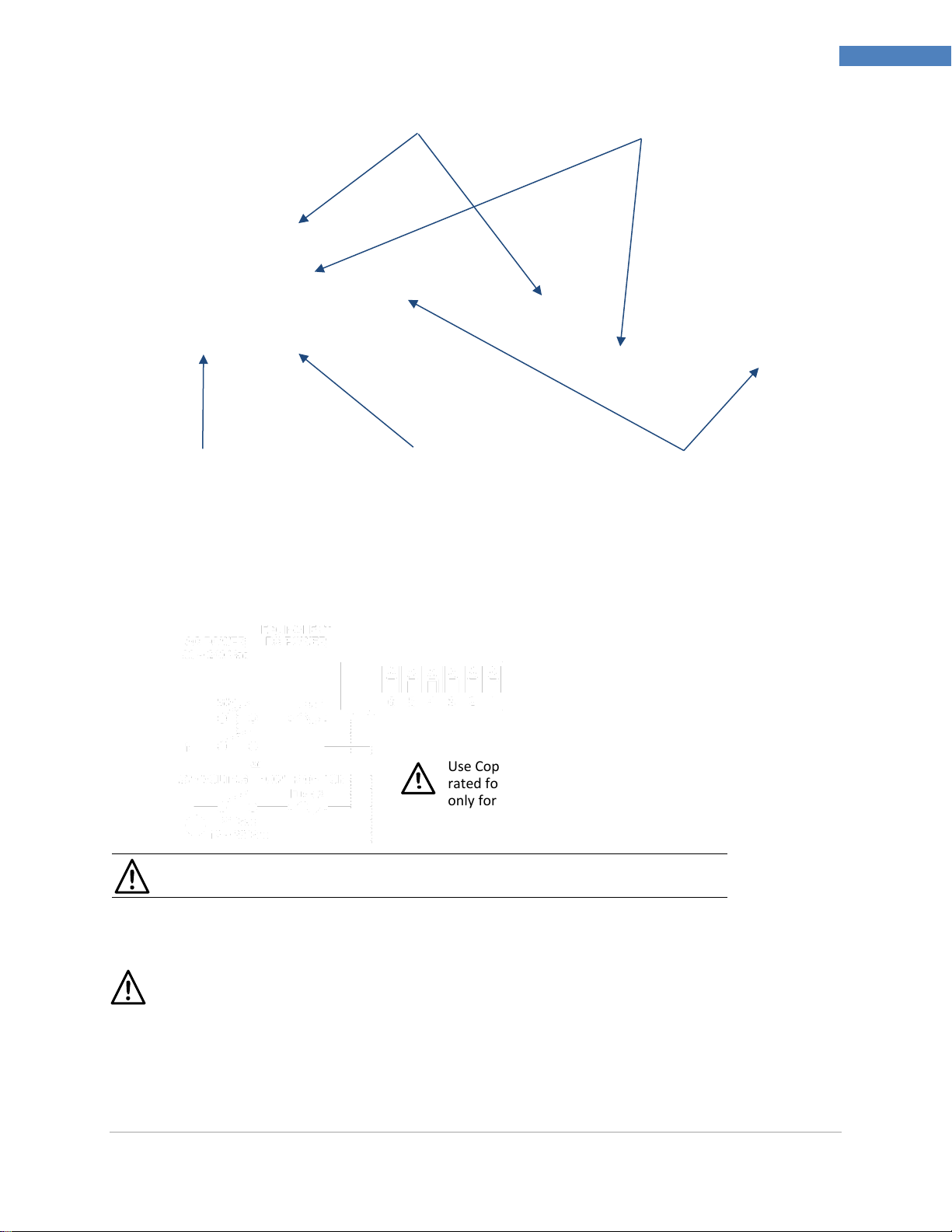
Caution: Do not connect power to your device until you have completed all input
and output connections. Failure to do so may result in injury!
Use Copper Conductors
rated for 75
only for Power Connections
Ethernet Communications Status
LEDs if EIP Option Installed
Ethernet Connector if EIP
Option Installed
8-Pin Power / Outputs Connector
10-Pin Input Connector
USB Connector (on side,
cable stub shown)
110 ~ 300 Vdc
Figure 3 – CN16Pt and CN32Pt Models: Back Panel Connections
3.2 Connecting Power
Connect the main power connections to pins 7 and 8 of the 8-pin power / output connector as shown in
Figure 4.
Figure 4 – Main Power Connections
For the low-voltage power option, maintain the same degree of protection as the standard highvoltage input power units (90–240 Vac) by using a Safety Agency Approved DC or AC source with
the same Overvoltage Category and pollution degree as the standard AC unit (90–300 Vac).
The Safety European Standard EN61010-1 for measurement, control, and laboratory equipment
requires that fuses must be specified based on IEC127. This standard specifies the letter code “T”
for a Time-lag fuse.
C min
M5451 Omega Engineering | www.omega.com
Page 12

PLATINUMTM Series Controllers User’s Guide
12
Wiring Instructions
Pin No.
Code
Description
1
ARTN
Analog return signal (analog ground) for sensors and remote Setpoint
2
AIN+
Analog positive input
3
AIN-
Analog negative input
4
APWR
Analog power currently only used for 4-wire RTDs
5
AUX
Auxiliary analog input for remote Setpoint
6
EXCT
Excitation voltage output referenced to ISO GND
7
DIN
Digital input signal (latch reset, etc.), Positive at > 2.5V, ref. to ISO GND
8
ISO GND
Isolated ground for serial communications, excitation, and digital input
9
RX/A
Serial communications receive
10
TX/B
Serial communications transmit
Pin
Number
Diff
Voltage
Process
Voltage
Process
Current
Thermo-
couple
2-Wire
RTD
3-Wire
RTD
4-Wire
RTD
Thermistor
Remote
Setpoint
1 Rtn
**
RTD2-
RTD2+
Rtn(*)
2
Vin +/-
Vin +/-
I+
T/C+
RTD1+
RTD1+
RTD1+
TH+ 3
Vd +/-
I-
T/C-
RTD2-
TH- 4
RTD1-
RTD1-
RTD1-
5
V/I In
3.3 Connecting Inputs
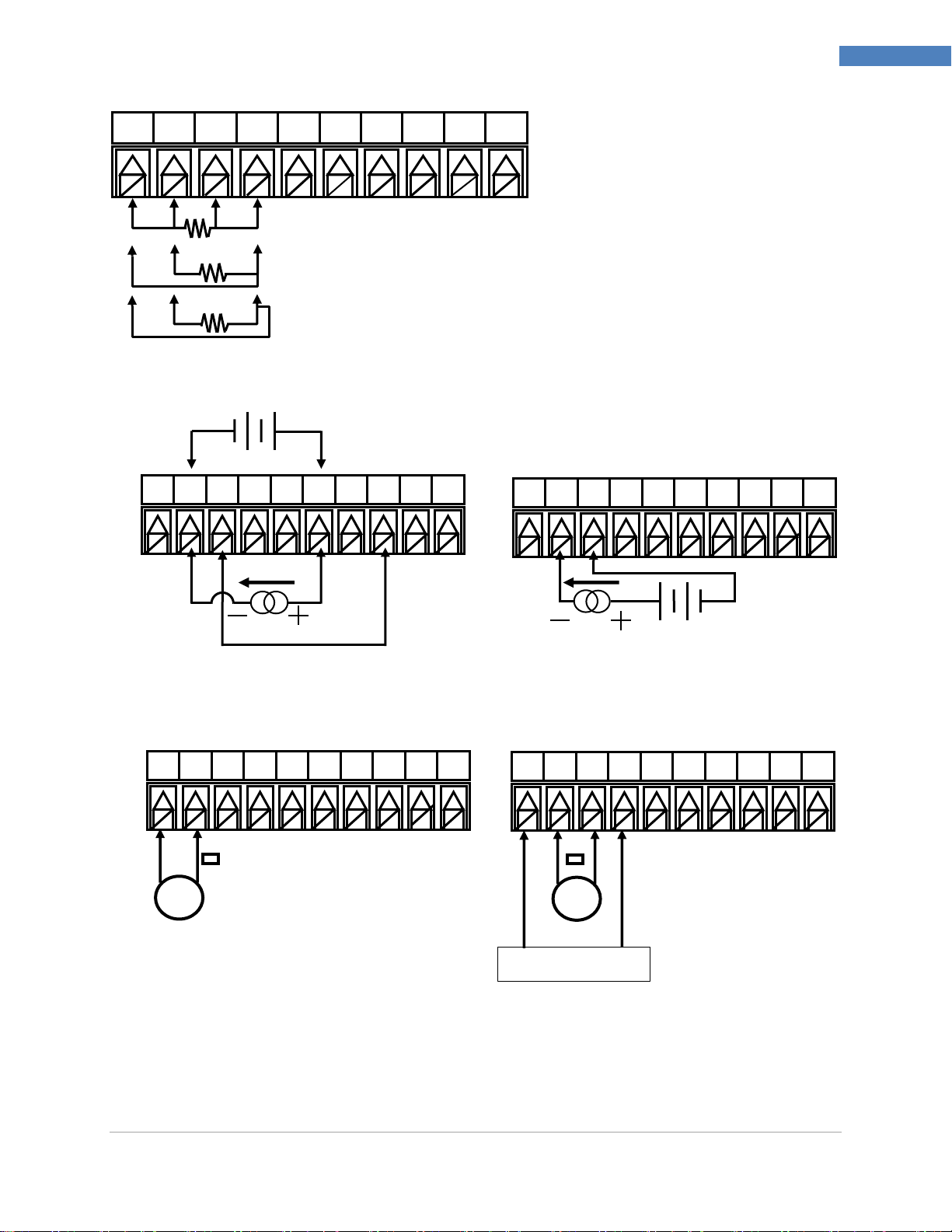
The 10-pin universal input connector assignments are summarized in Table 1. Table 2 provides detail for
the specific types of sensors supported. All sensor selections are firmware-controlled (see 4.1 Input
Configuration (INIt > INPt)) and no jumper settings are required when switching from one type of sensor
to another. Figure 5 provides more detail for connecting RTD sensors. Figure 6 shows the connection
scheme for process current input with either internal or external excitation. Figure 7 shows the
connections for Single Ended and Differential input voltages.
Table 1 – 10-Pin Input Connector Wiring Summary
Table 2 – Interfacing Sensors to the Input Connector
*For Remote Setpoint with an RTD, Pin 1 on the Output Connector must be used for the RtN instead of Pin 1 on the
Input Connector. Remote Setpoint is not available if using an RTD sensor and have an SPDT (Type 3) Output
installed.
** Requires external connection to pin 4
M5451 Omega Engineering | www.omega.com
Page 13
PLATINUMTM Series Controllers User’s Guide
13
Wiring Instructions
External
Excitation
Internal
1
2 3 4 5 6 7 8
9
10
1 2 3 4 5 6 7 8 9
10
RTD (100 Ω) 4-WIRE
RTD (100 Ω) 3-WIRE
RTD (100 Ω) 2-WIRE (requires
pin 1 to be jumped to pin 4)
1 2 3 4 5 6 7 8 9
10
0–24 mA
Excitation
1 2 3 4 5 6 7 8 9
10
1 2 3 4 5 6 7 8 9
10
+/- 10, +/- 1 and +/- 0.1
Single End Voltage
+/- 0.1and +/- .05 Differential /
Ratiometric Voltage
Reference Voltage
Figure 5 – RTD Wiring Diagram
Internal
Figure 6 – Process Current Wiring Hookup with Internal and External Excitation
Figure 7 – Process Voltage Wiring Hookup with optional Ratiometric Voltage connection.
M5451 Omega Engineering | www.omega.com
Page 14
PLATINUMTM Series Controllers User’s Guide
14
Wiring Instructions
Code
Output Type
1
3A Mechanical single pole, single throw (SPST) mechanical relay
2
1A Solid state relay (SSR)
3
3A Mechanical single pole, double throw (SPDT) mechanical relay
4
DC pulse for connecting to an external SSR
5
Analog current or voltage
6
Isolated Analog current or voltage (only on output expansion board for 1/8 DIN models)
7
Isolated DC pulse (“IDC” only on output expansion board for 1/8 DIN models)
Power
Output Pin Number
Config.
Description
8 7 6 5 4 3 2
1
330
SPDT, SPDT
AC+
or
DC+
AC-
or
DC-
N.O
Com
N.C
N.O
Com
N.C
304
SPDT, DC pulse
N.O
Com
N.C V+
Gnd
305
SPDT, analog
N.O
Com
N.C
V/C+
Gnd
144
SPST, DC pulse, DC pulse
N.O
Com
V+
Gnd
V+
Gnd
145
SPST, DC pulse, analog
N.O
Com
V+
Gnd
V/C+
Gnd
220
SSR, SSR
N.O
Com
N.O
Com
224
SSR, SSR, DC pulse
N.O
Com
N.O
Com
V+
Gnd
225
SSR, SSR, analog
N.O
Com
N.O
Com
V/C+
Gnd
440
DC pulse, DC pulse
V+
Gnd
V+
Gnd
444
DC pulse, DC pulse, DC pulse
V+
Gnd
V+
Gnd
V+
Gnd
445
DC pulse, DC pulse, analog
V +
Gnd
V+
Gnd
V/C+
Gnd
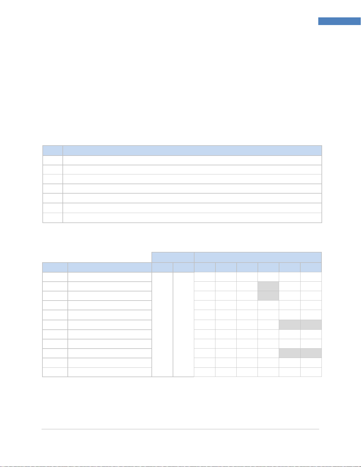
3.4 Connecting Outputs
The PLATINUMTM Series supports 7 different types of outputs with the model number numeric
designations summarized in Table 3. The unit comes preconfigured with up to 3 outputs (up to 6 outputs
with 1/8 DIN models). Table 3 shows the base output connector connections for the different
configurations offered. The base output configuration is the 3 numeric digits following the first dash in
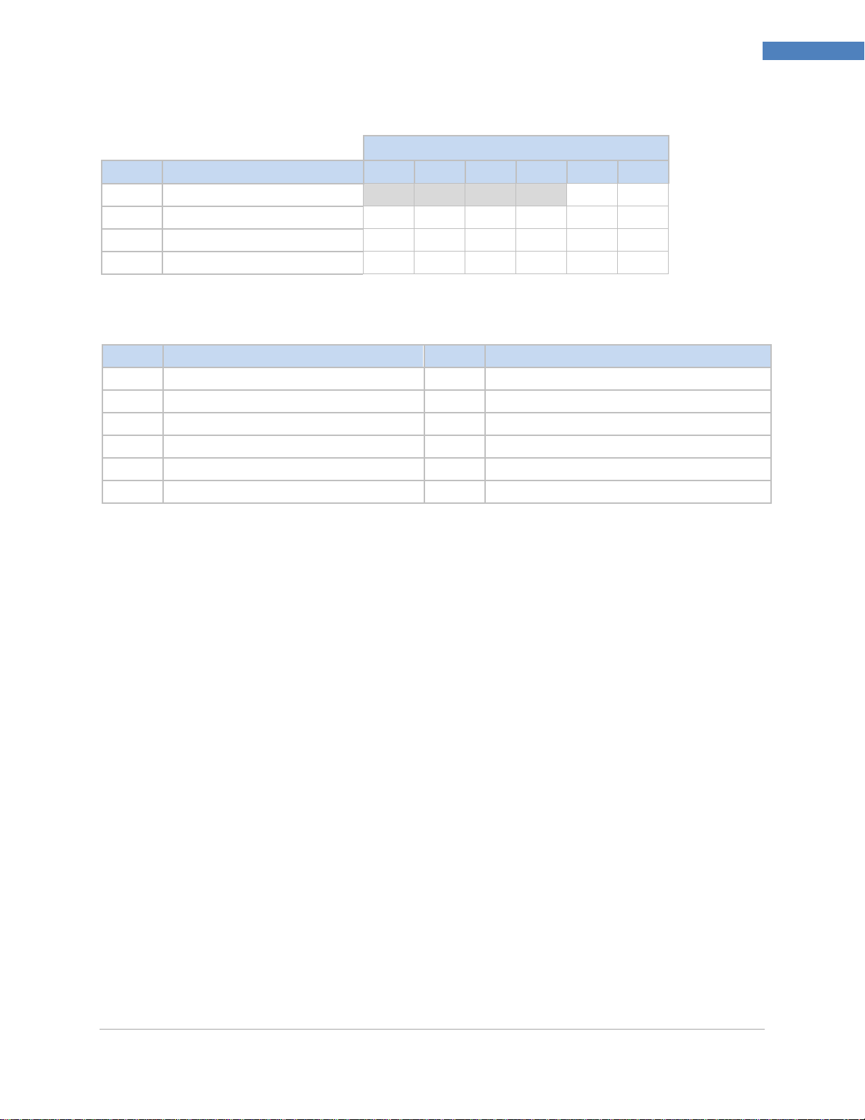
the model number. The optional isolated output expansion board offered on 1/8 DIN models can add 1
or 3 additional isolated outputs with the numeric codes and connection positions shown in Table 3.
Table 4 defines the abbreviated codes used in Tables 5 and 6. Please note that the SPST and SPDT
mechanical relays have snubbers built in but only on the normally open contact side.
Table 3 – Output Type Designations for Base Output Connector.
Table 4 – 8 Pin Output/Power Connector Wiring Summary by Configuration.
M5451 Omega Engineering | www.omega.com
Page 15
PLATINUMTM Series Controllers User’s Guide
15
Wiring Instructions
Output Expansion Board Pin Number
Config.
Description
6 5 4 3 2
1
006
Isolated Analog
V/C+
Gnd
776
IDC, IDC, Isolated Analog
V+
Gnd
V+
Gnd
V/C+
Gnd
116
SPST, SPST, Isolated Analog
N.O
Com
N.O
Com
V/C+
Gnd
226
SSR, SSR, Isolated Analog
N.O
Com
N.O
Com
V/C+
Gnd
Code
Definition
Code
Definition
N.O.
Normally open relay/SSR load
AC-
AC power neutral in pin
Com
Relay Common/SSR AC power
AC+
AC power hot in pin
N.C.
Normally closed relay load
DC-
Negative DC power in pin
Gnd
DC Ground
DC+
Positive DC power in pin
V+
Load for DC pulse
V/C+
Load for analog
Table 5 – 6 Pin Output Expansion Board Connector Wiring Summary by Configuration.
Table 6 – Definitions for Abbreviations in Table 4.
M5451 Omega Engineering | www.omega.com
Page 16
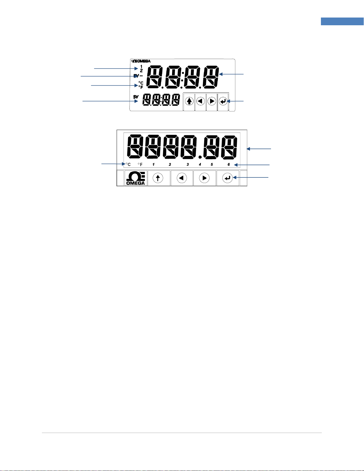
PLATINUMTM Series Controllers User’s Guide
16
PLATINUMTM Series Navigation
Alarm Annunciators
Negative Sign
Temperature Units
Setpoint Value
Process Value
Program Buttons
The UP button moves up a level in the menu structure. Pressing and holding the UP
button navigates to the top level of any menu (oPER, PRoG, or INIt). This can useful if
you get lost in the menu structure.
The LEFT button moves across a set of menu choices at a given level (up in the Section 4
menu structure tables). When changing numerical settings, press the LEFT button to
make the next digit (one digit to the left) active.
The RIGHT button across a set of menu choices at a given level (down in the Section 4
menu structure tables. The RIGHT button also scrolls numerical values up with overflow
to 0 for the flashing digit selected.
The ENTER button selects a menu item and goes down a level, or it enters a numerical
value or parameter choice.
Program Buttons
Process Value
Temperature Units
Alarm Annunciators
4. PLATINUM
TM
Series Navigation
Figure 8 – PLATINUM Series Displays (CN8DPt and CN8EPt Shown)
4.1 Description of Button Actions
4.2 Menu Structure
The menu structure of the PLATINUMTM Series is divided into 3 main Level 1 groups, which are
Initialization, Programming, and Operating. They are described in Section 4.3. The complete menu
structure for levels 2 to 8 for each of the three Level 1 groups is detailed in Section 5.1, 5.2, and 5.3.
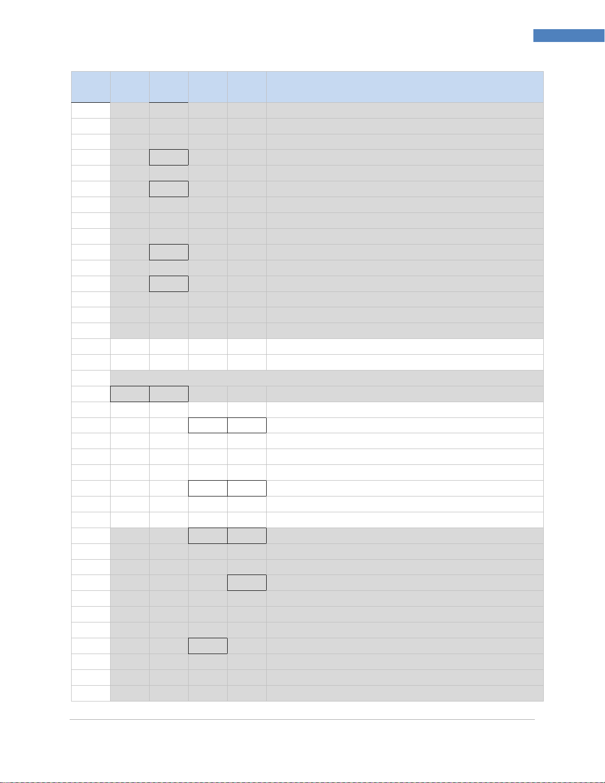
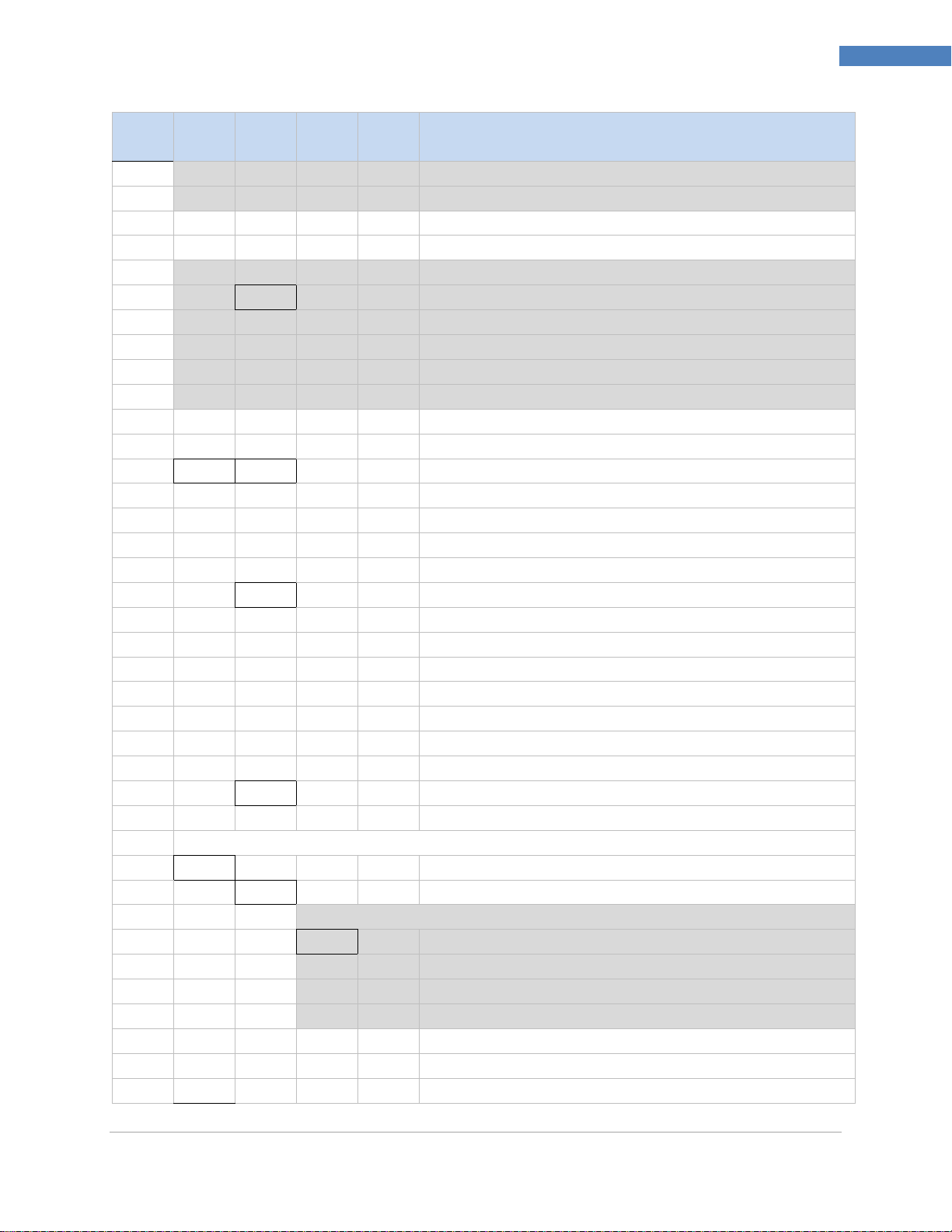
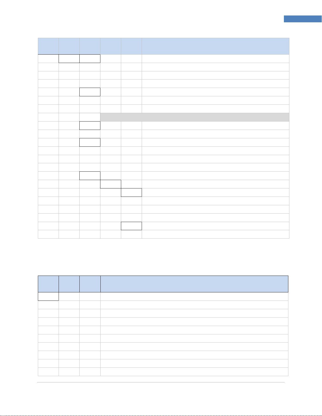
Levels 2 through 8 represent sequentially deeper levels of navigation. Values with a dark box around
them are default values or submenu entry points. Blank lines indicate user-provided information. Some
menu items include links to reference information elsewhere in this user manual. The information in the
Notes column defines each menu choice.
M5451 Omega Engineering | www.omega.com
Page 17

PLATINUMTM Series Controllers User’s Guide
17
PLATINUMTM Series Navigation
Initialization Mode: These settings are rarely changed after initial setup. They include
transducer types, calibration, etc. These settings can be password-protected.
Programming Mode: These settings are frequently changed. They include Set points,
Control Modes, Alarms, etc. These settings can be password-protected.
Operating Mode: This mode allows users to switch between Run Mode, Standby Mode,
Manual Mode, etc.
INIt
PRoG
oPER
4.3 Level 1 Menu
4.4 Circular Flow of Menus
The following diagram shows how to use the LEFT and RIGHT buttons to navigate around a menu.
Figure 9 – Circular Flow of Menus.
M5451 Omega Engineering | www.omega.com
Page 18
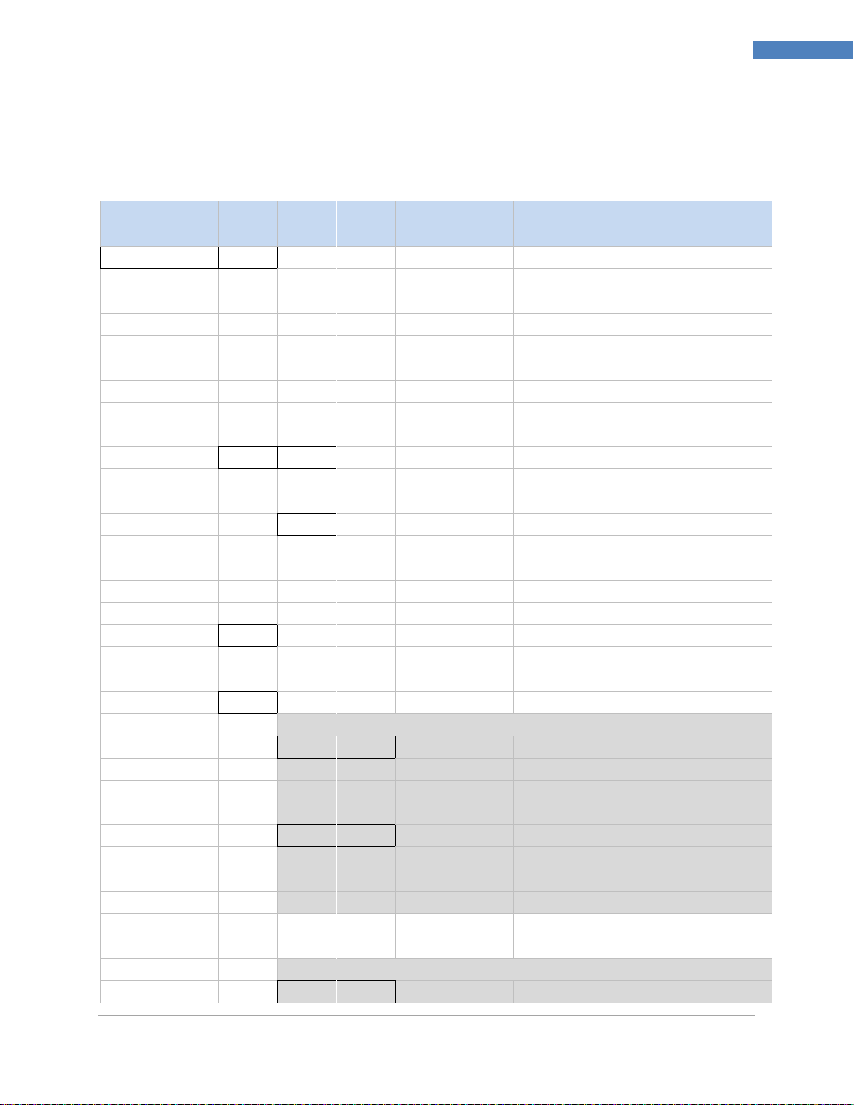
PLATINUMTM Series Controllers User’s Guide
18
Complete Menu Structure
Level
2
Level
3
Level
4
Level
5
Level
6
Level
7
Level
8
Notes
INPt
t.C. k Type K thermocouple
J
Type J thermocouple
t
Type T thermocouple
E
Type E thermocouple
N
Type N thermocouple
R
Type R thermocouple
S
Type S thermocouple
b
Type B thermocouple
C
Type C thermocouple
Rtd
N.wIR
3 wI 3-wire RTD
4 wI 4-wire RTD
2 wI 2-wire RTD
A.CRV
385.1 385 calibration curve, 100 Ω
385.5 385 calibration curve, 500 Ω
385.t 385 calibration curve, 1000 Ω
392 392 calibration curve, 100 Ω
391.6 391.6 calibration curve, 100 Ω
tHRM
2.25k
2250 Ω thermistor
5k
5000 Ω thermistor
10k
10,000 Ω thermistor
PRoC
4–20
Process input range: 4 to 20 mA
Note: This Manual and Live Scaling submenu is the same for all PRoC ranges.
MANL
Rd.1
____
Low display reading
IN.1
____
Manual input for Rd.1
Rd.2
____
High display reading
IN.2
____
Manual input for Rd.2
LIVE
Rd.1
____
Low display reading
IN.1
____
Live Rd.1 input, ENTER for current
Rd.2
____
High display reading
IN.2
____
Live Rd.2 input, ENTER for current
0–24
Process input range: 0 to 24 mA
+-10
Process input range: -10 to +10 V
Note: +- 1.0 and +-0.1 support SNGL, dIFF and RtIO tYPE
+-1
tYPE
SNGL
Process input range: -1 to +1 V
5. Complete Menu Structure
5.1 Initialization Mode Menu (INIt)
The following table maps the Initialization Mode (INIt) navigation:
M5451 Omega Engineering | www.omega.com
Page 19
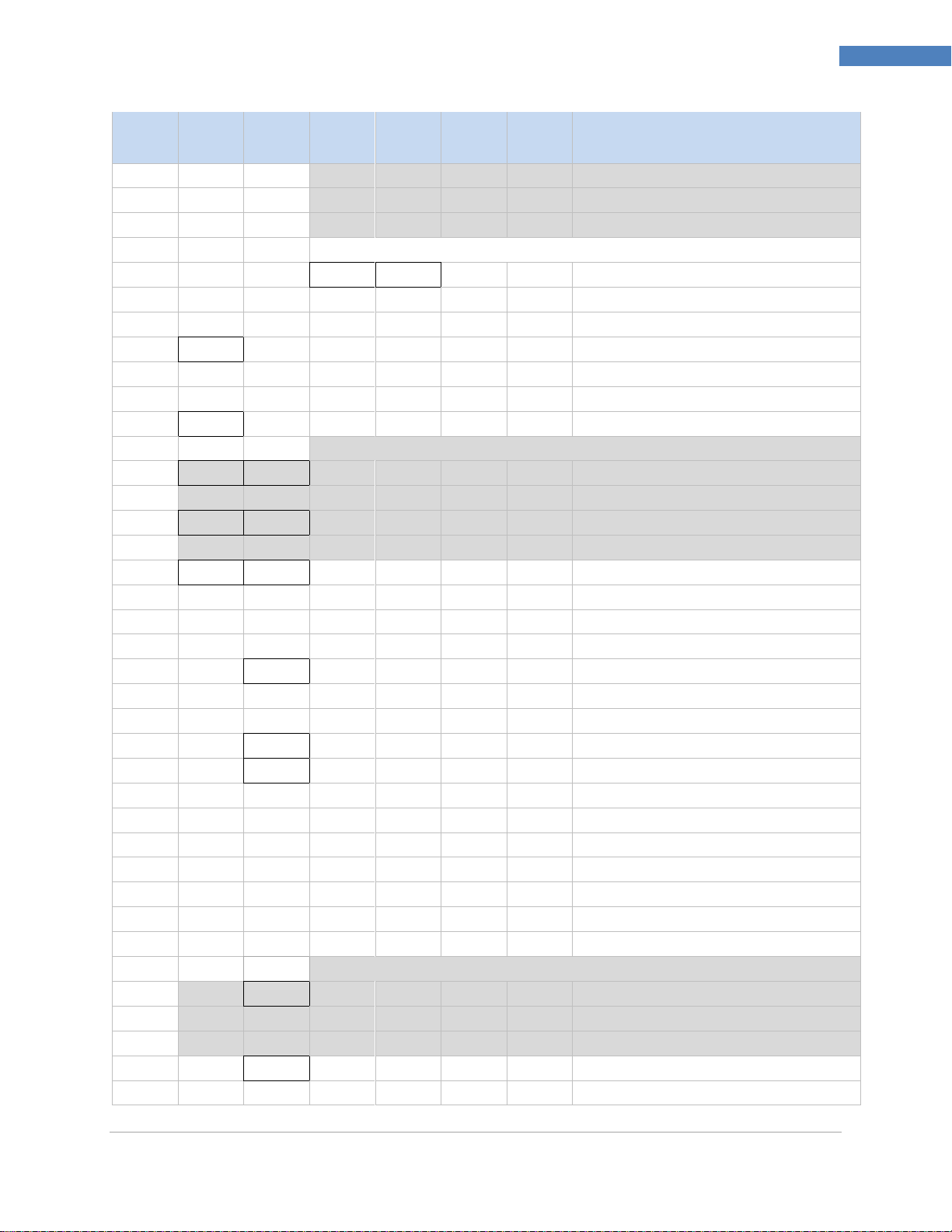
PLATINUMTM Series Controllers User’s Guide
19
Complete Menu Structure
Level
2
Level
3
Level
4
Level
5
Level
6
Level
7
Level
8
Notes
dIFF
Differential between AIN+ and AIN-
RtLO
Ratiometric between AIN+ and AIN-
+-0.1
Process input range: -0.1 to +0.1 V
Note: The +- 0.05 input supports dIFF and RtIO tYPE
+-.05
tYPE
dIFF
Differential between AIN+ and AIN-
RtLO
Ratiometric between AIN+ and AIN-
Process input range: -0.05 to +0.05 V
tARE
dSbL Disable tARE feature
ENbL Enable tARE on oPER menu
RMt Enable tARE on oPER and Digital Input
LINR
N.PNt
_____
Specifies the number of points to use
Note: The Manual / Live inputs repeat from 1..10, represented by n
MANL
Rd.n
____ Low display reading
IN.n
____ Manual input for Rd.n
LIVE
Rd.n
____ Low display reading
IN.n
____ Live Rd.n input, ENTER for current
RdG
dEC.P
FFF.F
Reading format -999.9 to +999.9
FFFF
Reading format -9999 to +9999
FF.FF
Reading format -99.99 to +99.99
F.FFF
Reading format -9.999 to +9.999
°F°C
°C
Degrees Celsius annunciator
°F
Degrees Fahrenheit annunciator
NoNE
Turns off for non-temperature units
d.RNd
_____
Display Rounding
FLtR 8 Readings per displayed value: 8
16
16
32
32
64
64
128
128 1 2 2 3 4 4
Note: Four digit displays offer 2 annunciators, Six digit displays offer 6
ANN.n
ALM.1
Alarm 1 status mapped to “1”
ALM.2
Alarm 2 status mapped to “1”
oUt#
Output state selections by name
NCLR
GRN
Default display color: Green
REd
Red
M5451 Omega Engineering | www.omega.com
Page 20

PLATINUMTM Series Controllers User’s Guide
20
Complete Menu Structure
Level
2
Level
3
Level
4
Level
5
Level
6
Level
7
Level
8
Notes
AMbR
Amber
bRGt
HIGH
High display brightness
MEd
Medium display brightness
Low
Low display brightness
ECtN
5 V Excitation voltage: 5 V
10 V 10 V 12 V 12 V
24 V 24 V 0 V Excitation off
CoMM
USb Configure the USB port
Note: This PRot submenu is the same for USB, Ethernet, and Serial ports.
PRot
oMEG
ModE
CMd
Waits for commands from other end
CoNt
____
Transmit continuously every ###.# sec
dAt.F
StAt
No
yES
Includes Alarm status bytes
RdNG
yES
Includes process reading
No
PEAk
No
yES
Includes highest process reading
VALy
No
yES
Includes lowest process reading
UNIt
No yES
Send unit with value (F, C, V, mV, mA)
_LF_
No
yES
Appends line feed after each send
ECHo
yES
Retransmits received commands
No
SEPR
_CR_
Carriage Return separator in CoNt
SPCE
Space separator in CoNt Mode
M.bUS
RtU
Standard Modbus protocol
ASCI
Omega ASCII protocol
AddR
____ USB requires Address
EtHN
PRot
Ethernet port configuration
AddR
____ Ethernet “Telnet” requires Address
SER
PRot
Serial port configuration
C.PAR
bUS.F
232C
Single device Serial Comm Mode
485
Multiple devices Serial Comm Mode
bAUd
19.2
Baud rate: 19,200 Bd
M5451 Omega Engineering | www.omega.com
Page 21

PLATINUMTM Series Controllers User’s Guide
21
Complete Menu Structure
Level
2
Level
3
Level
4
Level
5
Level
6
Level
7
Level
8
Notes
9600
9,600 Bd
4800
4,800 Bd
2400
2,400 Bd
1200
1,200 Bd
57.6
57,600 Bd
115.2
115,200 Bd
PRty
odd
Odd parity check used
EVEN
Even parity check used
NoNE
No parity bit is used
oFF
Parity bit is fixed as a zero
dAtA
8bIt
8 bit data format
7bIt
7 bit data format
StoP
1bIt
1 stop bit
2bIt
2 stop bits gives a “force 1” parity bit
AddR
____ Address for 485, placeholder for 232
SFty
PwoN
RSM
RUN on power up if not previously faulted
wAIt
Power on: oPER Mode, ENTER to run
RUN
RUN’s automatically on power up
RUN.M
dSbL
ENTER in Stby, PAUS, StoP runs
ENbL
ENTER in modes above displays RUN
SP.LM
SP.Lo
____ Low Setpoint limit
SP.HI
____ High Setpoint limit
SEN.M Sensor Monitor
LPbk
dSbL Loop break timeout disabled
ENbL Loop break timeout value (MM.SS)
o.CRk
ENbl Open Input circuit detection enabled
dSbL Open Input circuit detection disabled
E.LAt
ENbl Latch sensor error enabled
dSbL Latch sensor error disabled
OUT.M
Output Monitor
oUt1
oUt1 is replaced by output type
o.bRk Output break detection
dSbL
Output break detection disabled
ENbl
P.dEV
____
Output break process deviation
P.tME
____
Output break time deviation
oUt2
oUt2 is replaced by output type
oUt3
oUt3 is replaced by output type
E.LAt
ENbl Latch output error enabled
M5451 Omega Engineering | www.omega.com
Page 22
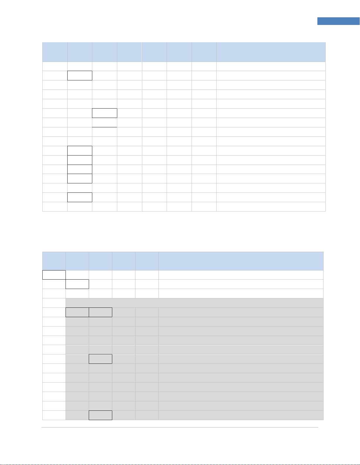
PLATINUMTM Series Controllers User’s Guide
22
Complete Menu Structure
Level
2
Level
3
Level
4
Level
5
Level
6
Level
7
Level
8
Notes
dSbL Latch output error disabled
t.CAL
NoNE Manual temperature calibration
1.PNt Set offset, default = 0
2.PNt
R.Lo
Set range low point, default = 0
R.HI
Set range high point, default = 999.9
ICE.P
ok?
Reset 32°F/0°C reference value
dSbL
Clears the ICE.P offset value
SAVE
____ Download current settings to USB
LoAd
____ Upload settings from USB stick
VER.N
1.00.0 Displays firmware revision number
VER.U
ok? ENTER downloads firmware update
F.dFt
ok? ENTER resets to factory defaults
I.Pwd
No No required password for INIt Mode
yES
____
Set password for INIt Mode
P.Pwd
No No password for PRoG Mode
yES
____
Set password for PRoG Mode
Level
2
Level
3
Level
4
Level
5
Level
6
Notes
SP1
____ Process goal for PID, default goal for oN.oF
SP2
ASbo Setpoint 2 value can track SP1, SP2 is an absolute value
dEVI SP2 is a deviation value
ALM.1
Note: This submenu is the same for all other Alarm configurations.
tyPE
oFF
ALM.1 is not used for display or outputs
AboV
Alarm: process value above Alarm trigger
bELo
Alarm: process value below Alarm trigger
HI.Lo.
Alarm: process value outside Alarm triggers
bANd
Alarm: process value between Alarm triggers
Ab.dV
AbSo
Absolute Mode; use ALR.H and ALR.L as triggers
d.SP1
Deviation Mode; triggers are deviations from SP1
d.SP2
Deviation Mode; triggers are deviations from SP2
CN.SP
Tracks the Ramp & Soak instantaneous setpoint
ALR.H
____
Alarm high parameter for trigger calculations
ALR.L
____
Alarm low parameter for trigger calculations
A.CLR
REd
Red display when Alarm is active
5.2 Programming Mode Menu (PRoG)
The following table maps the Programming Mode (PRoG) navigation:
M5451 Omega Engineering | www.omega.com
Page 23
PLATINUMTM Series Controllers User’s Guide
23
Complete Menu Structure
Level
2
Level
3
Level
4
Level
5
Level
6
Notes
AMbR
Amber display when Alarm is active
GRN
Green display when Alarm is active
dEFt
Color does not change for Alarm
HI.HI
oFF
High High / Low Low Alarm Mode turned off
oN
____
Offset value for active High High / Low Low Mode
LtCH
No
Alarm does not latch
yES
Alarm latches until cleared via front panel
botH
Alarm latches, cleared via front panel or digital input
RMt
Alarm latches until cleared via digital input
CtCL
N.o.
Output activated with Alarm
N.C.
Output deactivated with Alarm
A.P.oN
yES
Alarm active at power on
No
Alarm inactive at power on
dE.oN
____
Delay turning off Alarm (sec), default = 1.0
dE.oF
____
Delay turning off Alarm (sec), default = 0.0
ALM.2
Alarm 2
oUt1
oUt1 is replaced by output type
Note: This submenu is the same for all other outputs.
ModE
oFF
Output does nothing
PId
PID Control Mode
ACtN
RVRS
Reverse acting control (heating)
dRCt
Direct acting control (cooling)
RV.DR
Reverse/Direct acting control (heating/cooling)
PId.2
PID 2 Control Mode
ACtN
RVRS
Reverse acting control (heating)
dRCt
Direct acting control (cooling)
RV.DR
Reverse/Direct acting control (heating/cooling)
oN.oF
ACtN
RVRS
Off when > SP1, on when < SP1
dRCt
Off when < SP1, on when > SP1
dEAd
____
Deadband value, default = 5
S.PNt
SP1
Either Setpoint can be used of on/off, default is SP1
SP2
Specifying SP2 allows two outputs to be set for heat/cool
ALM.1
Output is an Alarm using ALM.1 configuration
ALM.2
Output is an Alarm using ALM.2 configuration
RtRN
Rd1
____
Process value for oUt1
oUt1
____
Output value for Rd1
Rd2
____
Process value for oUt2
oUt2
____
Output value for Rd2
M5451 Omega Engineering | www.omega.com
Page 24
PLATINUMTM Series Controllers User’s Guide
24
Complete Menu Structure
Level
2
Level
3
Level
4
Level
5
Level
6
Notes
RE.oN
Activate during Ramp events
SE.oN
Activate during Soak events
SEN.E
Activate if any sensor error is detected
OPL.E
Activate if any output is open loop
CyCL
____
PWM pulse width in seconds
RNGE
0-10
Analog Output Range: 0–10 Volts
0-5
0–5 Volts
0-20
0–20 mA
4-20
4–20 mA
0-24
0–24 mA
oUt2
oUt2 is replaced by output type
oUt3
oUt3 is replaced by output type (1/8 DIN can have up to 6)
PId
ACtN
RVRS
Increase to SP1 (i.e., heating)
dRCt
Decrease to SP1 (i.e., cooling)
RV.DR
Increase or Decrease to SP1 (i.e., heating/cooling)
A.to
____
Set timeout time for autotune
tUNE
StRt
Initiates autotune after StRt confirmation
GAIN
_P_
____
Manual Proportional Band setting
_I_
____
Manual Integral Factor setting
_d_
____
Manual Derivative Factor setting
rCg
____
Relative Cool Gain (heating/cooling mode)
oFst
____
Control Offset
dEAd
____
Control Dead band/Overlap band (in process unit)
%Lo
____
Low clamping limit for Pulse, Analog Outputs
%HI
____
High clamping limit for Pulse, Analog Outputs
AdPt
ENbL
Enable fuzzy logic adaptive tuning
dSbL
Disable fuzzy logic adaptive tuning
PId.2
Note: This menu is the same for PID menu.
RM.SP
oFF Use SP1, not remote Setpoint
oN
4–20
Remote analog Input sets SP1; range: 4–20 mA
Note: This submenu is the same for all RM.SP ranges.
RS.Lo
____
Min Setpoint for scaled range
IN.Lo
____
Input value for RS.Lo
RS.HI
____
Max Setpoint for scaled range
IN.HI
____
Input value for RS.HI
0–24
0–24 mA
0–10
0–10 V
0–1
0–1 V
M5451 Omega Engineering | www.omega.com
Page 25
PLATINUMTM Series Controllers User’s Guide
25
Complete Menu Structure
Level
2
Level
3
Level
4
Level
5
Level
6
Notes
M.RMP
R.CtL
No
Multi-Ramp/Soak Mode off
yES
Multi-Ramp/Soak Mode on
RMt
M.RMP on, start with digital input
S.PRG
____
Select program (number for M.RMP program), options 1–99
M.tRk
RAMP
Guaranteed Ramp: soak SP must be reached in ramp time
SoAk
Guaranteed Soak: soak time always preserved
CYCL
Guaranteed Cycle: ramp can extend but cycle time can’t
Note: tIM.F does not appear for 6 digit display that use a HH:MM:SS format
tIM.F
MM:SS
“Minutes : Seconds” default time format for R/S programs
HH:MM
“Hours : Minutes” default time format for R/S programs
E.ACt
StOP
Stop running at the end of the program
HOLd
Continue to hold at the last soak setpoint at program end
LINk
____
Start the specified ramp & soak program at program end
N.SEG
____
1 to 8 Ramp/Soak segments (8 each, 16 total)
S.SEG
____
Select segment number to edit, entry replaces # below
MRt.#
____
Time for Ramp number, default = 10
MRE.#
oFF
Ramp events on for this segment
oN
Ramp events off for this segment
MSP.#
____
Setpoint value for Soak number
MSt.#
____
Time for Soak number, default = 10
MSE.#
oFF
Soak events off for this segment
oN
Soak events on for this segment
Level
2
Level
3
Level
4
Notes
RUN
Normal Run Mode, process value displayed, SP1 in optional secondary display
SP1
____
Shortcut to change Setpoint 1, current Setpoint 1 value in main display
SP2
____
Shortcut to change Setpoint 2, current Setpoint 2 value in main display
MANL
M.CNt
____
Manual Mode, the RIGHT and LEFT buttons control output, displays M##.#
M.INP
____
Manual Mode, the RIGHT and LEFT buttons simulate the input for testing
PAUS
Pause and hold at current process value, display flashes
StoP
Stop controlling, turn off outputs, process value rotating flash, Alarms remain
L.RSt
Clears any latched Alarms; Alarms menu also allows digital input reset
VALy
Displays the lowest input reading since the VALy was last cleared
PEAk
Displays the highest input reading since the PEAk was last cleared
5.3 Operating Mode Menu (oPER)
The following table maps the Operating Mode (oPER) navigation:
M5451 Omega Engineering | www.omega.com
Page 26

PLATINUMTM Series Controllers User’s Guide
26
Complete Menu Structure
Level
2
Level
3
Level
4
Notes
Stby
Standby Mode, outputs, and Alarm conditions disabled, displays Stby
tARE
TARE option - only available if enabled in INPt
M5451 Omega Engineering | www.omega.com
Page 27
PLATINUMTM Series Controllers User’s Guide
27
Reference Section: Initialization Mode (INIt)
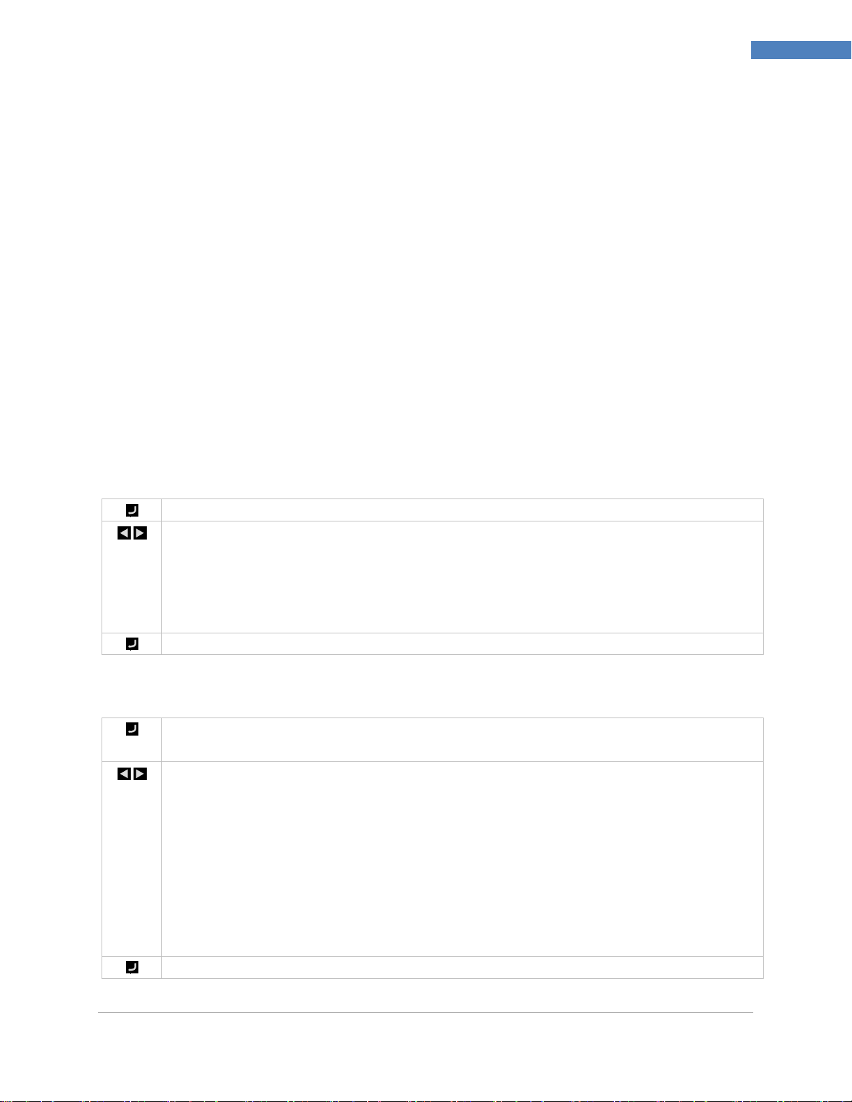
Select the Input parameter (INPt) to configure the input.
Navigate to the correct setting. Settings include the following:
t.C. – Thermocouple Temperature Sensor (entry point)
Rtd – Resistance Temperature Detector (RTD)
tHRM – Thermistor Temperature Sensor
PRoC – Process Voltage or Current Input
Select the indicated setting.
Select Thermocouple (t.C.) as the input type (factory default). Then specify a specific type of
thermocouple or the last selected type will be used.
Navigate to the installed thermocouple type. Supported types are as follows:
k – Type K (factory default)
J – Type J
t – Type T
E – Type E
N – Type N
R – Type R
S – Type S
b – Type B
C – Type C
Select the indicated type.
6. Reference Section: Initialization Mode (INIt)
Use Initialization Mode to set the following parameters and perform the following functions:
6. Reference Section: Initialization Mode (INIt) ..................................................................................... 27
6.1 Input Configuration (INIt > INPt) ................................................................................................. 27
6.2 TARE (INIt > tARE) ....................................................................................................................... 34
6.3 LINR (INIt > LINR) ......................................................................................................................... 34
6.4 Display Reading Formats (INIt > RdG) ......................................................................................... 36
6.5 Excitation Voltage (INIt > ECtN) .................................................................................................. 39
6.6 Communication (INIt > CoMM) ................................................................................................... 39
6.7 Safety Features (INIt > SFty) ........................................................................................................ 42
6.8 Manual Temperature Calibration (INIt > t.CAL) .......................................................................... 44
6.9 Save Current Configuration for All Parameters to a File (INIt > SAVE) ....................................... 46
6.10 Load a Configuration for All Parameters from a File (INIt > LoAd) ............................................. 46
6.11 Display Firmware Revision Number (INIt > VER.N) ..................................................................... 46
6.12 Update Firmware Revision (INIt > VER.U) ................................................................................... 47
6.13 Reset to Factory Default Parameters (INIt > F.dFt) ..................................................................... 47
6.14 Password-Protect Initialization Mode Access (INIt > I.Pwd) ....................................................... 47
6.15 Password-Protect Programming Mode Access (INIt > P.Pwd) .................................................... 47
6.1 Input Configuration (INIt > INPt)
6.1.1 Thermocouple Input Type (INIt > INPt > t.C.)
M5451 Omega Engineering | www.omega.com
Page 28
PLATINUMTM Series Controllers User’s Guide
28
Reference Section: Initialization Mode (INIt)
Select Rtd as the input type. Factory default configuration settings are three-wire, 100 Ω,
using the European standard 385 curve. Note that the 392 and 3916 curves are only available
for 100 Ω RTDs. If Rtd is selected and a specific configuration is not changed, the last saved
configuration will be used.
Navigate to the desired configuration parameter:
N.wIR – Firmware selection of the number of wires for RTD connection (no jumpers
needed)
A.CRV – Calibration curve covering both the international standard and the
resistance of the RTD
Select the option.
Navigate to the desired setting. Settings include the following:
3 wI – Three-wire RTD (factory default)
4 wI – Four-wire RTD
2 wI – Two-wire RTD
Select the indicated option.
Navigate to the desired setting. Settings include the following:
385.1 – European and most common standard at the conventional
resistance of 100 Ω (factory default)
385.5 – European curve for 500 Ω
385.t – European curve for 1000 Ω
392 – Old US standard (rarely used), at 100 Ω only
3916 – Japanese standard, at 100 Ω only
Select the indicated option.
Select Thermistor (tHRM) as the input type. This sets up the unit for thermistor-based
temperature measurement and then the specific thermistor type can be specified. If no
thermistor type is specified, the last selected type is used.
Navigate to the correct setting. Settings include the following:
2.25k – 2,250 Ω thermistor (factory default)
5k – 5,000 Ω thermistor
10k – 10,000 Ω thermistor
Select the indicated option.
6.1.2 Resistance Temperature Detector (RTD) Input Type (INIt > INPt >
Rtd)
6.1.2.1 Number of RTD Wires (INIt > INPt > Rtd >
N.wIR)
6.1.2.2 Calibration Curve (INIt > INPt > Rtd > A.CRV)
6.1.3 Thermistor Input Type Configuration (INIt > INPt > tHRM)
M5451 Omega Engineering | www.omega.com
Page 29

PLATINUMTM Series Controllers User’s Guide
29
Reference Section: Initialization Mode (INIt)
Select Process (PRoC) as the input type. Then select the process input range and scale it. If
stopped after selecting the PRoC input type, the last selected input range and scaling is used.
Navigate to the voltage or current range of the process input. Any signal input outside of the
specified hardware input range will result in an “out-of-range” error (code E009). Input range
choices include the following:
4–20 – 4 mA to 20 mA (factory default)
0–24 – 0 mA to 24 mA
+–10 – -10 V to +10 V
+–1 – -1 V to +1 V
+–0.1 – -100 mV to +100 mV
+–.05 – -50 mV to +50 mV
Select the desired range.
The (tYPE) option is only displayed for +- 1.0, +-0.1 and +- .05 inputs and allows selecting
between Single Ended, Differential and Ratiometric inputs. The +- .05 input only supports dIFF
and RtIo input types.
SNGL – Bipolar Single Ended voltage between A+ and ARTN connections
dIFF – Differential voltage between A+ and A- connections
RTIo – Ratiometric reading between A+ and A- connections.
Select the desired type.
Choose either manual or live scaling. The scaling functions translate process values to
engineering units and are available for all process input ranges. The defaults for each input
range are the hardware minimum and maximum. Scaling methods include the following:
MANL – User manually enters all four scaling parameters
LIVE – User manually enters the low and high display values (RD.1 and RD.2) but
reads the input signal directly to set the low and high input values (IN.1 and IN.2)
Using either MANL or LIVE to set up scaling, scaled values are then calculated as:
Scaled Value = Input * Gain + Offset, where:
Gain = (Rd.2 – Rd.1) / (IN.2 – IN.1)
Offset = Rd.1 – (Gain * IN.1)
Therefore scaling can be done over a subset of the applicable range as this scaling calculation
linearly extrapolates in both directions.
Select the scaling method to be used.
6.1.4 Process Input Type Configuration (INIt > INPt > PRoC)
M5451 Omega Engineering | www.omega.com
Page 30
PLATINUMTM Series Controllers User’s Guide
30
Reference Section: Initialization Mode (INIt)
Navigate to the desired scaling parameter. Options include the following:
Rd.1 – Reading low value corresponding to IN.1 signal
IN.1 – Input signal corresponding to RD.1
Rd.2 – Reading high value corresponding to IN.2 signal
IN.2 – Input signal corresponding to RD.2
In Manual Mode, IN.1 and IN.2 are entered manually for scaling;, in Live Mode, IN.1 and IN.2
activate a read of the input signal for scaling.
Select the scaling parameter to change.
For manual inputs, set the selected scaling parameter to the desired value.
Confirm the value for the selected scaling parameter in Manual Mode (MANL), or read and
accept the input signal for either IN.1 or IN.2 in Live Mode (LIVE).
ARTN
V
AIN +
Max
Voltage
V
AIN +
Reference
Common
Voltage
AIN -
ARTN
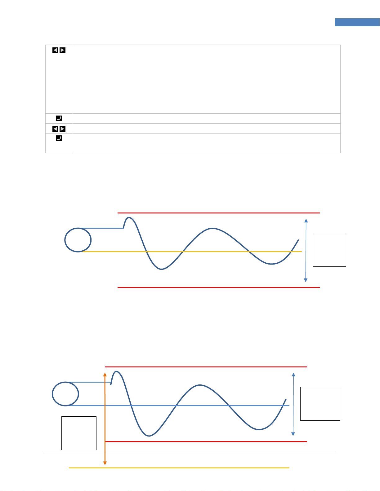
6.1.4.1 Single Ended Inputs
Single Ended inputs measure the voltage on the Analog Input terminal (AI+) with respect to the analog
ground (ARTN) terminal.
Input
6.1.4.1 Differential Inputs
Differential inputs measure the voltage difference between the AIN+ and AIN- terminals. An internal
2.048 reference voltage (Vref) is used and determines the maximum voltage difference. The analog
voltages must be within +/- 2.0 volts of the analog ground (ARTN) voltage level, referred to as the
Common Mode Voltage.
Mode
M5451 Omega Engineering | www.omega.com
Voltage
Page 31
PLATINUMTM Series Controllers User’s Guide
31
Reference Section: Initialization Mode (INIt)
V
Reference
Common
Voltage
ARTN
AIN +
AIN -
Measured Signal as %
of Reference Voltage
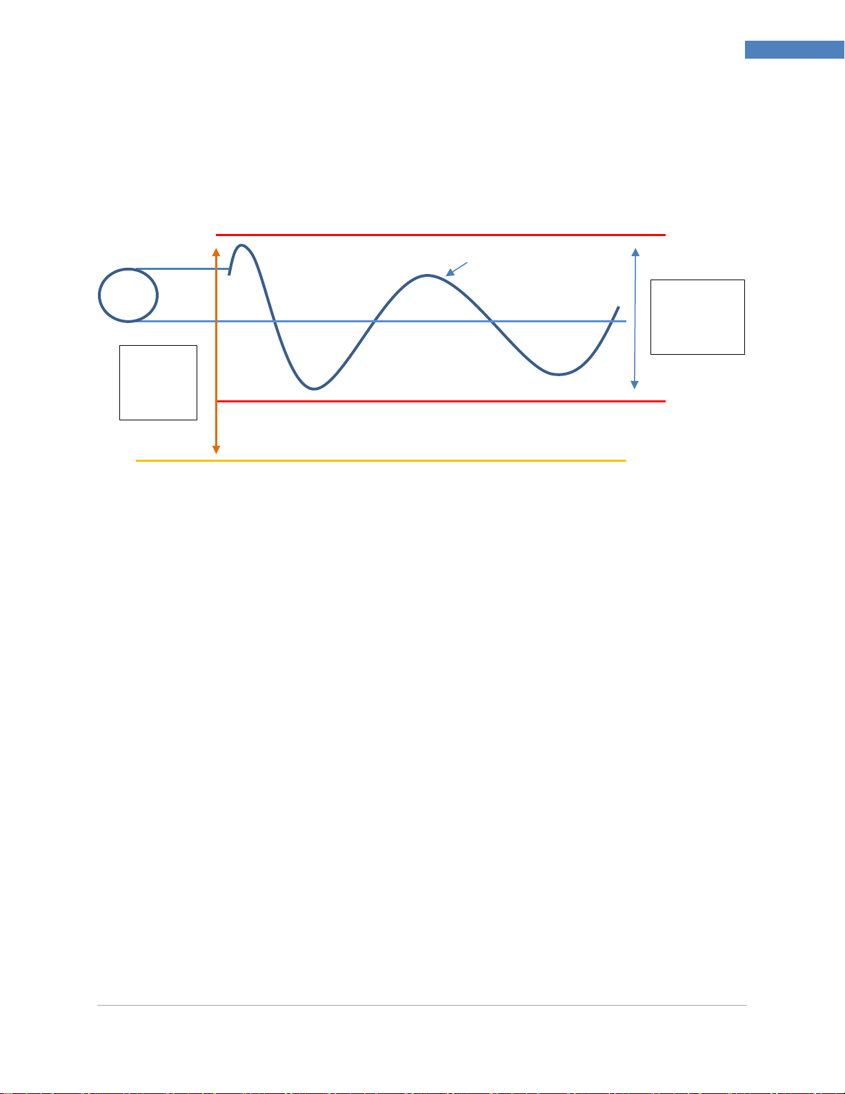
6.1.4.1 Ratiometric Inputs
Ratiometric inputs allow applying an external reference voltage (Vref) used by the Analog / Digital
converter and the measured signal level directly proportional to the reference voltage. The external
reference voltage must be in the range of 1.5 – 2.5 Vdc and applied between APWR and ARTN. An
internal 2.0 k ohm resistor is applied between the APWR and ARTN terminals.
Mode
Voltage
M5451 Omega Engineering | www.omega.com
Page 32
PLATINUMTM Series Controllers User’s Guide
32
Reference Section: Initialization Mode (INIt)
Bridge Element
1 2 3 4 5 6 7 8 9
R1
R2
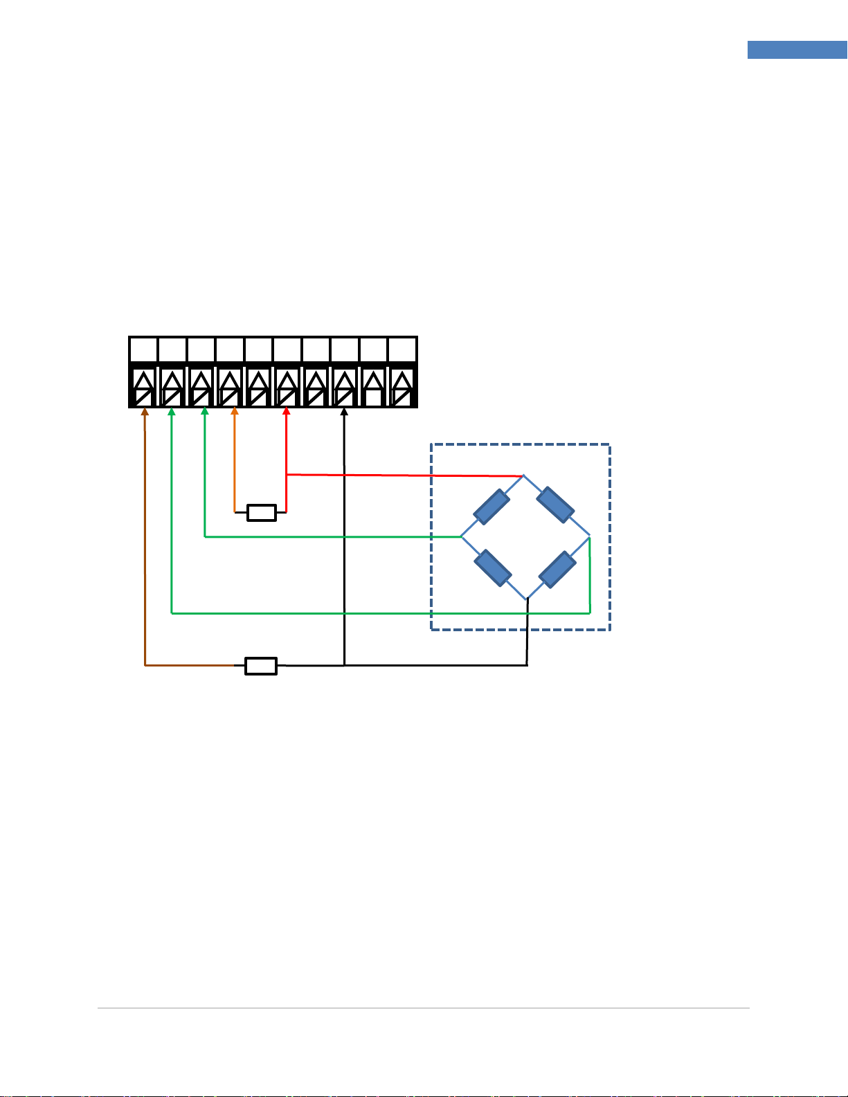
6.1.4.2 Bridge Inputs
Ratiometric inputs are widely used for bridge inputs as found in load cell and pressure sensors because
any fluctuations in the excitation voltage are eliminated in the final reading.
The input is configured as a ratiometric input, where the voltage difference between terminals 2 (AIN+)
and 3 (AIN-) is measured with respect to the externally applied voltage reference applied between
terminal 1 (ARTN) and terminal 4 (APWR).
The Excitation voltage, set to 5 or 10 Vdc is used to power the external bridge sensor. Two external
resistors provide a divider circuit to ensure that the differential inputs are biased at ½ of the voltage
generated by the on-board Excitation Voltage.
10
Resistors (R1, R2): ~ 4.7 k ohms.
NOTE: An internal 2.0 k ohms resistor is connected between terminal 1 (ARTN) and terminal 4
(APWR).
M5451 Omega Engineering | www.omega.com
Page 33

PLATINUMTM Series Controllers User’s Guide
33
Reference Section: Initialization Mode (INIt)
X
6.1.4.3 Bridge (Ratiometric) Input Scaling
To calibrate to a specific bridge device, the user must provide two known loads and enter the
corresponding values. This allows the device to calculate a straight line correction:
Weight = Input Reading X Gain + Offset
Scaling operations allow translating source (input) signals to scaled output signal using a linear
translation defined by a SLOPE (or gain) and an OFFSET. As shown below, (X1, Y1) and (X2, Y2) define
two points on a line that has a certain SLOPE and OFFSET. Knowing the SLOPE and OFFSET allows
determining the OUTPUT value for any given INPUT value using the equation:
Output = Input X SLOPE + OFFSET, where
GAIN = (Y2 - Y1) / (X2 - X1)
OFFSET = Y1 - (GAIN * X1).
The Input reading is expressed in terms of full scale, which is directly dependent on the applied
reference voltage which is in turn derived from the excitation voltage. Due to the ratiometric design the
absolute value of the Excitation voltage and exact resistor values do not enter into the weight
calculation.
If (X2 - X1) == 0, the GAIN is set to 1 and the OFFSET is set to 0.
M5451 Omega Engineering | www.omega.com
Page 34

PLATINUMTM Series Controllers User’s Guide
34
Reference Section: Initialization Mode (INIt)
Select TARE (tARE) to configure the tare option.
Navigate to the desired setting. Settings include the following:
dSbL – No TARE option is enabled
ENbL – TARE option may be activated from RUN menu
RMt – TARE option may be activated from RUN menu or by digital input
The Tare option is only available for process inputs. If enabled (ENbL or RMt) the OPERATING
menu is expanded to include a TARE option that allows zeroing the reading value when the
unit is in the RUN mode.
If the remote option is selected the reading may be zeroed using either the panel button or
the digital input while in the RUN mode.
When activated, the TARE process applies an offset adjustment to the current reading such
that the adjusted reading will be zero.
Select the indicated setting.
Select 10 Point Linearization option. The 10 point linearization allows entering up to 10
Reading/Input value pairs used to internally calculate 10 gain/offset parameters. The LINR
option is only available on Process inputs.
Select the Number of Points (N.PNt
The N.Pts option determines how many of the Reading/Input pairs are processed. To disable
the Linearization function set the Number of points to 0.
Select the indicated setting.
Choose either manual or live inputs. The defaults for each input pair 100.0 Reading and 100.0
Input Scaling methods include the following:
MANL – User manually enters both parameters
LIVE – User manually enters the display values (RD.n) but the signal level is read
from the input set the input values (IN.n)
Using either MANL or LIVE linearization Gain/Offset pairs are calculated as:
Gain = (Rd.n – Rd.n-1) / (IN.n – IN.n-1)
Offset = Rd.n-1 – (Gain * IN.n-1)
During processing the input level is compared to the set of input levels stored to determine
which gain/offset pair to apply.
Select the linearization method to be used.
Navigate to the desired scaling parameter. Options include the following:
Rd.n – Reading low value corresponding to IN.1 signal
IN.n – Input signal corresponding to RD.1
In Manual Mode, IN.n is entered manually. In Live Mode, the IN.n option displays the current
input signal.
Select the scaling parameter to change.
6.2 TARE (INIt > tARE)
6.3 LINR (INIt > LINR)
M5451 Omega Engineering | www.omega.com
Page 35
PLATINUMTM Series Controllers User’s Guide
35
Reference Section: Initialization Mode (INIt)
Ptx
Raw Input
Output Value
Level = Gain2 X Weight + Offset2
Level = Gain
X Weight + Offset
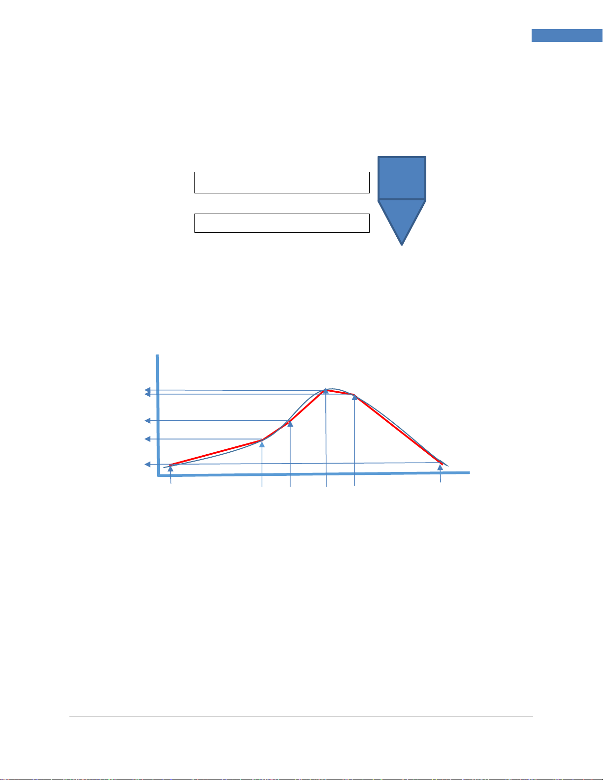
In many applications a single Gain and Offset as provided by the Scaling adjustment on process inputs
can be used that supports a direct linearization between the input signal and the required reading. For
more complex applications, the relationship between the input value and the desired reading is not
linear across the entire range of inputs. A common example is found when converting a measured
weight of an irregular shaped hopper to the equivalent level.
A 10-point linearization table is provided, allowing for piecewise linearization of complex profiles. This
feature is often used to transform weight values into volume or to transform primary measurements
into derived measurements such as rate of change in temperature to air flow.
The internal process sequentially checks each Point (IN.x) value against the raw input and uses the
associated Gain (GN.x) value to calculate the transfer function.
Combined Scaling/Linearization
The Scaling and 10-point Linearization may be combined. The output of the Scaling adjustment is
applied as the input to the 10-point linearization.
The use of Live Scaling and Live Linearization is mutually exclusive. If Live scaling is selected the Live
Linearization option is disabled and if Live Linearization is selected the Live Scaling option is disabled.
M5451 Omega Engineering | www.omega.com
Page 36
PLATINUMTM Series Controllers User’s Guide
36
Reference Section: Initialization Mode (INIt)
Select Reading Formats (RdG) to configure the front panel display.
Navigate to the desired setting. Settings include the following:
dEC.P – Decimal-point format (entry point)
°F°C – Temperature units
d.RNd – Display Rounding
FLtR – Filter (readings displayed per second)
ANN.n – Annunciator 1..n setting, number determined by 6 digit display type
NCLR – Normal color (default display color)
bRGt – Display brightness
Select the indicated setting.
Select Decimal Point (dEC.P) and then select the desired decimal-point format. Only the FFF.F
and FFFF formats work for temperature inputs but all four can be used with process inputs.
While this parameter sets the default format, the numeric display will auto range
(automatically shift the decimal point) if necessary.
Navigate to the desired setting. Settings include the following:
FFF.F – One decimal place (factory default)
FFFF – Zero decimal places
FF.FF – Two decimal places (not a choice with temperature inputs)
F.FFF – Three decimal places (not a choice with temperature inputs)
Select the indicated format.
Select the Temperature Units (°F°C) parameter, and the current temperature unit selection is
then displayed.
Navigate to the desired setting. Settings include the following:
°C – Degrees Celsius (factory default), °C annunciator turned on
°F – Degrees Fahrenheit, °F annunciator turned on
NoNE – Default for INPt = PRoC, both temp unit annunciators turned off; if the
process level input signal corresponds to a temperature (temperature transmitters for
example), the appropriate temperature type annunciator can be chosen.
Select the indicated option.
6.4 Display Reading Formats (INIt > RdG)
6.4.1 Decimal Point Format (INIt > RdG > dEC.P)
6.4.2 Temperature Units (INIt > RdG > °F°C)
M5451 Omega Engineering | www.omega.com
Page 37

PLATINUMTM Series Controllers User’s Guide
37
Reference Section: Initialization Mode (INIt)
Select the Display Rounding (d.Rnd) option.
The Display Rounding parameter determines the minimum change in value required to cause
the display to update.
For example, if the d.RNd value is set to 5.0, the displayed values will be 0, 5, 10….
The D.RND value only affects the value being displayed. It does not affect the absolute value
being read or the value(s) used for control functions.
Select the indicated option.
Select the Filter (FLtR) parameter. Filtering averages multiple input analog to digital
conversions, which can suppress noise in the input signal. This should be set to an appropriate
value depending on the response time of the input.
Navigate to the desired setting corresponding to the number of readings per displayed value.
Settings include the following (calculated times between display value updates are shown for
each setting as well):
8 – 0.4 s (factory default)
16 – 0.8 s
32 – 1.6 s
64 – 3.2 s
128 – 6.4 s
1 – 0.05 s
2 – 0.1 s
4 – 0.2 s
Select the indicated option.
6.4.3 Display Rounding (INIt > RdG > d.RNd)
6.4.4 Filter (INIt > RdG > FLtR)
M5451 Omega Engineering | www.omega.com
Page 38

PLATINUMTM Series Controllers User’s Guide
38
Reference Section: Initialization Mode (INIt)
Select the Annunciator 1 (ANN.1) parameter. This controls which Alarm or output status
activates the “1” annunciator on the front display. In general, the default values for both
annunciators should be used (status for Alarm configuration 1 for annunciator 1 and status for
Alarm configuration 2 for annunciator 2). However, it can be useful during troubleshooting to
map the on/off status of one or two outputs to the annunciators.
The ANN.1 and ANN.2 parameters work the same way except that they control the “1” and
the “2” front display annunciators, respectively, and have different default values.
Navigate to the desired setting. Settings include the following:
ALM.1 – The configuration defined by PRoG > ALM.1 determines the state of the
annunciator. The annunciator turns on when the Alarm condition exists (factory
default for ANN.1).
ALM.2 – The configuration defined by PRoG > ALM.2 determines the state of the
annunciator (factory default for ANN.2).
oUt# – “oUt#” is replaced by a list of the names of all outputs that are not analog
outputs. For example, the output choices dtR.1 and dC.1 are listed for a “145”
configuration, and ANG.1 is not listed.
Select the indicated option.
Select the Normal Color (NCLR) parameter. This controls the default display color, which can
then be overridden by Alarms.
Navigate to the desired setting. Settings include the following:
GRN – Green (factory default)
REd – Red
AMbR – Amber
Select the indicated option.
Select the Brightness (bRGt) parameter.
Navigate to the desired setting. Settings include the following:
HIGH – High display brightness (factory default)
MEd – Medium display brightness
Low – Low display brightness
Select the indicated option.
6.4.5 Annunciator Settings (INIt > RdG > ANN.1/ANN.2)
6.4.6 Normal Color (INIt > RdG > NCLR)
6.4.7 Brightness (INIt > RdG > bRGt)
M5451 Omega Engineering | www.omega.com
Page 39
PLATINUMTM Series Controllers User’s Guide
39
Reference Section: Initialization Mode (INIt)
Select the Excitation Voltage (ECtN) parameter.
Navigate to the correct setting. Settings include the following:
5 V – 5 Volt excitation voltage (factory default)
10 V – 10 Volt excitation voltage
12 V – 12 Volt excitation voltage
24 V – 24 Volt excitation voltage
0 V – Excitation turned off
Select the indicated option.
Select the Communication Type (CoMM) to configure. Only installed communications options
show up for configuration (USB is always present). If more than one communications option is
installed, any or all of them can be configured for simultaneous operation.
Navigate to the correct option. Options include the following:
USb – Universal Serial Bus (USB) communications
EtHN – Ethernet communications configuration
SER – Serial (either RS232 or RS485) communications configuration
Select the indicated option.
Navigate to the desired parameter submenu. Options include the following:
PRot – Protocol
AddR – Address
Note: The serial communications (SER) option above also includes the following parameter:
C.PAR – Communications parameters only applicable to serial communications
Select the indicated option.
Select the Protocol (PRot) parameter.
Navigate to the desired setting. Settings include the following:
oMEG – (factory default) Omega’s Protocol, using standard ASCII encoding. Further
detail on this format is covered in the Communications Manual.
M.bUS – Modbus protocol, available as Modbus RTU (RtU, default) or
Modbus/ASCII (ASCI). The Ethernet option supports Modbus/TCPIP. More detail on
using this protocol can be found in the Communications Manual.
Select the desired setting.
6.5 Excitation Voltage (INIt > ECtN)
6.6 Communication (INIt > CoMM)
6.6.1 Protocol (INIt > CoMM > USb, EtHN, SER > PRot)
M5451 Omega Engineering | www.omega.com
Page 40
PLATINUMTM Series Controllers User’s Guide
40
Reference Section: Initialization Mode (INIt)
Select oMEG to configure Omega ASCII mode communications parameters. These
configuration settings are the same for USB, Ethernet, and Serial communications.
Navigate to the desired parameter. Parameters and sub-parameters include the
following:
ModE – Choose the Mode for initiating ASCII data transfer:
o CMd – Data is sent after receiving a prompt command from the
connected device (factory default).
o CoNt – Data is sent as it is collected; setting the seconds between
data sends (###.#), default = 001.0. In Continuous Mode, sending a
CTRL/Q to the unit suspends transmission and sending a CTRL/S
restarts transmission.
dAt.F – Data Format; select yES or No for the following settings:
o StAt – Alarm status bytes are sent with the data
o RdNG – Sends the process reading
o PEAk – Sends the highest process reading so far
o VALy – Sends the lowest process reading so far
o UNIt – Sends the unit with the value (F, C, V, mV, mA)
_LF_ – Select yES or No; yES sends a line feed between each data block to
format the output in a more readable fashion.
ECHo – Select yES or No; yES echoes each received command to allow
verification.
SEPR – Determines the separation character between each data block:
o _CR_ – A carriage return sent between data blocks (factory
default).
o SPCE – A space character is sent between each data block.
Select the indicated option, and manage submenus and parameters as required.
Select the Address (AddR) parameter.
Set the Address value. The Modbus protocol requires an address field to correctly identify the
selected device. The Omega protocol supports an optional address field which is required for
Serial channels configured for RS485.
Accept the entered value.
6.6.1.1 ASCII Parameters (INIt > CoMM > USb, EtHN, SER
> PRot > oMEG)
M5451 Omega Engineering | www.omega.com
6.6.2 Address (INIt > CoMM > USb, EtHN, SER > AddR)
Page 41
PLATINUMTM Series Controllers User’s Guide
41
Reference Section: Initialization Mode (INIt)
Select C.PAR. Then, select individual parameters to configure the serial communications.
Navigate to the correct setting. Settings include the following:
bUS.F – Specify RS232 or RS485 serial communications
bAUd – Baud rate (transmission rate)
PRty – Parity (used for transmission error checking)
dAtA – Number of bits per data point
StoP – Number of stop bits between data points
Select the desired setting.
Select the Bus Format (bUS.F) parameter.
Navigate to the desired setting. Settings include the following:
232C – Allows one-to-one serial communications (factory default)
485 – Allows multiple devices to operate on a single pair of wires
Select the indicated option.
Select the Baud Rate (bAUd) parameter. The device being communicated to
determines how fast to set the Baud Rate.
Navigate to the desired setting for Baud rate (bits per second):
19.2 – 19,200 Baud (factory default)
9600 – 9,600 Baud
4800 – 4,800 Baud
2400 – 2,400 Baud
1200 – 1,200 Baud
57.6 – 57,600 Baud
115.2 – 115,200 Baud
Select the indicated option.
Select the Parity (PRty) parameter.
Navigate to the desired setting. Settings include the following:
odd – Odd parity used to verify communications (factory default)
EVEN – Even parity used to verify communications
NoNE – Parity is not used to verify communications
Select the indicated option.
6.6.3 Serial Communications Parameters (INIt > CoMM > SER >C.PAR)
6.6.3.1 Serial Bus Format (INIt > CoMM > SER > C.PAR >
bUS.F)
6.6.3.2 Baud Rate (INIt > CoMM > SER > C.PAR > bAUd)
6.6.3.3 Parity (INIt > CoMM > SER > C.PAR > PRty)
M5451 Omega Engineering | www.omega.com
Page 42
PLATINUMTM Series Controllers User’s Guide
42
Reference Section: Initialization Mode (INIt)
Select the number of Data Bits (dAtA).
Navigate to the desired setting. Settings include the following:
8bIt – 8 bits used per data character (factory default)
7bIt – 7 bits used per data character
Select the indicated option.
Select the number of Stop Bits (StoP).
Navigate to the desired setting. Settings include the following:
1bIt – 1 stop bit (factory default)
2bIt – 2 stop bits (provides a “force 1” parity bit)
Select the indicated option.
Select Safety Features (SFty).
Navigate to the desired parameter. Parameters include the following:
PwoN – Requires confirmation before running automatically at startup
oPER – User must select RUN when exiting from the Stby, PAUS, or StoP Modes
SP.LM – Setpoint limits can be set to limit the values that can be entered
LPbk – Loop break enable/disable and timeout value
o.CRk – Open circuit detection enable/disable
Select the indicated option.
Select Power On Confirmation (PwoN).
Navigate to the desired setting. Settings include the following:
RSM – Program runs automatically at startup if not previously in fault state
(factory default)
wAIt – The unit powers on and then displays RUN; press the ENTER button to run
the program
RUN – Program runs automatically at startup regardless of previous state
Select the desired setting.
Select the Operating Mode Confirmation (oPER) parameter.
Navigate to the desired setting. Settings include the following:
dSbL – Pressing the ENTER button in Stby, PAUS, or StoP Modes will start running
the current program immediately (factory default)
ENbL – Pressing the ENTER button in any Operating Menu Mode will display RUN;
pressing the ENTER button again will start running the current program
6.6.3.4 Data Bits (INIt > CoMM > SER > C.PAR > dAtA)
6.6.3.5 Stop Bits (INIt > CoMM > SER > C.PAR > StoP)
6.7 Safety Features (INIt > SFty)
6.7.1 Power On Confirmation (INIt > SFty > PwoN)
6.7.2 Operating Mode Confirmation (INIt > SFty > oPER)
M5451 Omega Engineering | www.omega.com
Page 43
PLATINUMTM Series Controllers User’s Guide
43
Reference Section: Initialization Mode (INIt)
Select the desired setting.
Select Setpoint Limits (SP.LM) to set limits on the values that can be used for the all Setpoints.
Navigate to the desired setting. Settings include the following:
SP.Lo – Set the minimum possible Setpoint value
SP.HI – Set the maximum possible Setpoint value
Select the desired setting.
Set the Setpoint limit value.
Confirm the value.
Select the loop break (LPbk) parameter. When enabled, this parameter specifies the amount
of time in Run Mode without a change in input value that would signify a sensor malfunction.
For example, if there were a problem in a thermocouple, the input would not change over
time.
Navigate to the desired setting. Settings include the following:
dSbL – No loop break timeout protection (factory default)
ENbL – Set loop break timeout value
Select the indicated setting.
If ENbL, Set the loop break timeout value in minutes and seconds (MM.SS)
Confirm the value.
Select the open circuit (o.CRk) parameter. When o.CRk is enabled, the unit will monitor
Thermocouples, RTD, and Thermistors for an open circuit condition.
Navigate to the desired setting. Settings include the following:
ENbL – Open circuit conditions will stop the program and display oPEN (factory
default)
dSbL – No open circuit protection (may be necessary when using high impedance
infrared thermocouples or thermistors).
Confirm the value.
Select the Error latch (E.LAT) parameter. When E.LAT is enabled, if any sensor error is
detected (open circuit, out of range, loop break), the unit will be put in fault mode. Manual
intervention is required to clear the error. When E.LAT is disabled, if the fault conditions no
longer exist, the unit will resume its previous running state.
6.7.3 Setpoint Limits (INIt > SFty > SP.LM)
6.7.4 Loop Break Timeout (INIt > SFty > SEN.M > LPbk)
6.7.5 Open Circuit (INIt > SFty > SEN.M > o.CRk)
6.7.6 Sensor Error Latch (INIt > SFty > SEN.M > E.LAT)
M5451 Omega Engineering | www.omega.com
Page 44
PLATINUMTM Series Controllers User’s Guide
44
Reference Section: Initialization Mode (INIt)
Navigate to the desired setting. Settings include the following:
ENbL – Enable sensor error latch. Manual intervention is required to clear the error.
dSbL – Disable sensor error latch. Unit automatically resumes if sensor errors are
cleared
Confirm the value.
Select the Output Break Detection (o.bRk) parameter. Output Break is detected when during
output saturation (i.e: PID is at 100%), the process value does not move the specified amount
of Process Deviation (P.dEV) in the specified amount of Time Deviation (T.dEV).
Navigate to the desired setting. Settings include the following:
ENbL – Enable Output break detection.
dSbL – Disable Output break detection
P.dEV – Process Deviation condition (in process units)
T.dEV – Time Deviation condition (in minutes)
Confirm the value.
Select the Error latch (E.LAT) parameter. When E.LAT is enabled, if any output error is
detected (output break detection), the unit will be put in fault mode. Manual intervention is
required to clear the error. When E.LAT is disabled, if the fault conditions no longer exist, the
unit will resume its previous running state.
Navigate to the desired setting. Settings include the following:
ENbL – Enable sensor error latch. Manual intervention is required to clear the error.
dSbL – Disable sensor error latch. Unit automatically resumes if sensor errors are
cleared
Confirm the value.
Select the Manual Temperature Calibration (t.CAL) submenu. This parameter allows manual
adjustment to the thermocouple, RTD, or Thermistor calibration curves provided with the
unit. Once a curve has been manually adjusted, this setting can be set to NoNE to disable the
manual adjustment (resetting to factory defaults will remove any manually adjustment
factors).
Navigate to the desired setting. Settings include:
NoNE – No manual calibration (factory default)
1.PNt – Manually create a 1-point calibration
2.PNt – Manually create a 2-point calibration
ICE.P – Manually create a 1-point calibration at 0oC
Select the indicated option.
6.7.7 Output Break detection (INIt > SFty > OUT.M > o.bRK)
6.7.8 Output Error Latch (INIt > SFty > OUT.M > E.LAT)
6.8 Manual Temperature Calibration (INIt > t.CAL)
M5451 Omega Engineering | www.omega.com
Page 45
PLATINUMTM Series Controllers User’s Guide
45
Reference Section: Initialization Mode (INIt)
Select NoNE to use the standard temperature sensor calibration curves. This mode will be
used by most users.
Select 1.PNt to manually adjust the offset of the calibration curve base on the current
reading.
Set the Manual Thermocouple Calibration Offset value in degrees.
Confirm the Offset value and pair it with the current input reading.
Select 2.PNt to use 2 points to manually adjust both the offset and slope of the calibration
curve.
Navigate to the desired setting. Settings include the following:
R.Lo – Set low point in degrees, default = 0, and associate with input reading
R.HI – Set high point in degrees, default = 999.9, and associate with input reading
Select the indicated setting.
Set the Temperature for R.Lo or R.HI.
Confirm the value and pair it with the current input reading.
6.8.1 No Manual Temperature Calibration Adjustment (INIt > t.CAL >
NoNE)
6.8.2 Manual Temperature Calibration Offset Adjustment (INIt > t.CAL
> 1.PNt)
6.8.3 Manual Temperature Calibration Offset and Slope Adjustment
(INIt > t.CAL > 2.PNt)
M5451 Omega Engineering | www.omega.com
Page 46
PLATINUMTM Series Controllers User’s Guide
46
Reference Section: Initialization Mode (INIt)
Select ICE.P to calibrate the zero point for the temperature sensor. This function basically
operates the same as a 1.PNT offset adjustment restricted to a measurement at the freezing
point of water.
Navigate to the ok? To set the ICE POINT value or DSBL to clear the previous ICE POINT offset.
Ok? – Offset is calculated, using assumed value of C.
dSbL– Clears the Ice Point offset value
Confirm the Ice Point set or reset.
Select Save Current Configuration Settings (SAVE) as the command to execute. If no thumb
drive is present the failure code E010 is displayed. Otherwise, a numeric designation for the
save file is then specified and confirmed before the SAVE command executes.
Important Note: The configuration file is a tab separated text file with a “.TXT” extension. It
can be loaded onto a PC, read into Excel then modified there. Once modified, save it back as
a tab separated .TXT file and it can then be loaded back into the unit using the INIt > LoAd
command. This capability can be especially useful for editing complex multi ramp and soak
programs. For more information on the configuration file format, see the “Load and Save File
Format Manual”.
Select a numeric file name from the range 0–99.
Confirm the SAVE command. This saves the configuration to the file number specified. If the
SAVE operation fails, the failure code w004 is displayed. If the SAVE operation is successful,
doNE is displayed.
Select the Load a Configuration (LoAd) command. If no thumb drive is present the failure code
E010 is displayed. Otherwise, a numeric designation for the file to be loaded is then specified
and confirmed before the LoAd command executes.
Select a numeric file name from the range 0–99.
Confirm the LoAd command. This loads the configuration from the file number specified. If
the LoAd operation fails, the failure code w003 is displayed. If the LoAd operation is
successful, doNE is displayed.
Select the Display Firmware Revision Number (VER.N) function. The currently installed version
number is displayed in the format 1.23.4 where “1” is the major revision number, “23” is the
minor revision number, and “4” is the bug fix update number.
6.8.4 Temperature Ice Point Calibration (INIt > t.CAL > ICE.P)
6.9 Save Current Configuration for All Parameters to a File (INIt > SAVE)
6.10 Load a Configuration for All Parameters from a File (INIt > LoAd)
6.11 Display Firmware Revision Number (INIt > VER.N)
M5451 Omega Engineering | www.omega.com
Page 47
PLATINUMTM Series Controllers User’s Guide
47
Reference Section: Initialization Mode (INIt)
Select the Update Firmware Revision (VER.U) function. Note that updating the firmware will
reset the unit to factory defaults. To keep all configuration settings, save them before
installing new firmware.
The LED display shows ok? and requires confirmation. Confirm the firmware update. New
firmware will then be read from a thumb drive connected to the USB port.
Select the Reset to Factory Default Parameters (F.dFt) function. The LED display shows ok?
and requires confirmation.
Confirm the parameter reset.
Select the Password Protect Initialization Mode Access (I.Pwd) function.
Navigate to the desired setting. Settings include the following:
No – Do not require a password for INIt Mode (factory default)
yES – Require a password for INIt Mode; users will be prompted for this password
when selecting INIt
Select the indicated setting.
If yES, set the numeric password from the range 0000–9999.
Confirm the password.
Select the Password Protect Programming Mode Access (P.Pwd) function.
Navigate to the desired setting. Settings include the following:
No – Do not require a password for PRoG Mode (factory default)
yES – Require a password for PRoG Mode; users will be prompted for this password
when selecting PRoG
Select the indicated setting.
If yES, set the numeric password from the range 0000–9999.
Confirm the password.
6.12 Update Firmware Revision (INIt > VER.U)
6.13 Reset to Factory Default Parameters (INIt > F.dFt)
6.14 Password-Protect Initialization Mode Access (INIt > I.Pwd)
6.15 Password-Protect Programming Mode Access (INIt > P.Pwd)
M5451 Omega Engineering | www.omega.com
Page 48

PLATINUMTM Series Controllers User’s Guide
48
Reference Section: Programming Mode (PRoG)
Select the Setpoint 1 (SP1) parameter.
Set the process goal value for PId or oN.oF control.
Confirm the value.
Select the Setpoint 2 (SP2) parameter. SP2 is used with Alarm functions and with on/off
control when setting up for Heat/Cool Control Mode.
Navigate to the desired setting. Settings include the following:
ASbo – The value for SP2 is specified in Absolute Mode (factory default)
dEVI – The value specified for SP2 indicates an offset (positive or negative) from
SP1; this allows SP2 to track any changes to SP1 automatically
Select the indicated setting.
Set the correct value.
Confirm the value.
7. Reference Section: Programming Mode (PRoG)
Use Programming Mode to set the following parameters and perform the following functions:
7. Reference Section: Programming Mode (PRoG) ................................................................................ 48
7.1 Setpoint 1 Configuration (PRoG > SP1) ....................................................................................... 48
7.2 Setpoint 2 Configuration (PRoG > SP2) ....................................................................................... 48
7.3 Alarm Mode Configuration (PRoG > ALM.1, ALM.2)................................................................... 49
7.4 Output Channel 1–6 Configuration (PRoG > oUt.1–oUt.6) ......................................................... 53
7.5 PID Configuration (PRoG > PId.S) ................................................................................................ 58
7.6 Remote Setpoint Configuration (PRoG > RM.SP) ........................................................................ 61
7.7 Multi-Ramp/Soak Mode Parameters (PRoG > M.RMP) .............................................................. 64
7.1 Setpoint 1 Configuration (PRoG > SP1)
7.2 Setpoint 2 Configuration (PRoG > SP2)
M5451 Omega Engineering | www.omega.com
Page 49

PLATINUMTM Series Controllers User’s Guide
49
Reference Section: Programming Mode (PRoG)
Select Alarm Configuration 1 (ALM.1) or Alarm Configuration 2 (ALM.2) in order to set up,
change, enable, or disable Alarms. Either or both Alarms can be assigned to trigger display
color changes, annunciators, and / or outputs. Either or both Alarm configurations can be
assigned to multiple outputs. The ALM.1 and ALM.2 configuration menus have all of the
same settings and function in the same manner.
Navigate to the Alarm setting to change. Settings include the following:
tyPE – Alarm type absolute or deviation
Ab.dV – Alarm references values (ALR.H and ALR.L) or deviation from SP1 or SP2
ALR.H – Alarm high parameter, used for Alarm trigger calculations
ALR.L – Alarm low parameter, used for Alarm trigger calculations
A.CLR – Alarm color indication
HI.HI – High High / Low Low offset value
LtCH – Alarm latching
CtCL – Alarm action (normally open or normally closed)
A.P.oN – Alarm power-on behavior
dE.oN – Time delay for Alarm trigger unless the condition persists, default = 1.0 s
dE.oF – Time delay for cancelling Alarms after being triggered; prevents Alarm
“chatter,” default = 0.0 s
Select the indicated setting.
Select the Alarm Type (tyPE) parameter. This parameter will control the basic behavior of the
selected alarm.
Navigate to the desired setting. Settings include the following:
oFF – Alarm is off (factory default)
AboV – Alarm is triggered when the process value exceeds ALR.H (Absolute Mode)
or the specified Setpoint plus ALR.H (Deviation Mode)
bELo – Alarm is triggered when the process value is less than ALR.L (Absolute
Mode) or the specified Setpoint minus ALR.L (Deviation Mode)
HI.Lo. – Alarm is triggered when the process value is outside the ALR.L–ALR.H range
(Absolute Mode) or the range defined by the band around the specified Setpoint as
determined by ALR.L and ALR.H (Deviation Mode)
bANd – Alarm is triggered when the process value is within the ALR.L–ALR.H range
(Absolute Mode) or within the band around the specified Setpoint as determined by
ALR.L and ALR.H (Deviation Mode)
Note: Table 5.1 compares the Alarm range options, and Figure 5.1 represents the Alarm range
options graphically.
Select the indicated setting.
7.3 Alarm Mode Configuration (PRoG > ALM.1, ALM.2)
7.3.1 Alarm Type (PRoG > ALM.1, ALM.2 > tyPE)
M5451 Omega Engineering | www.omega.com
Page 50
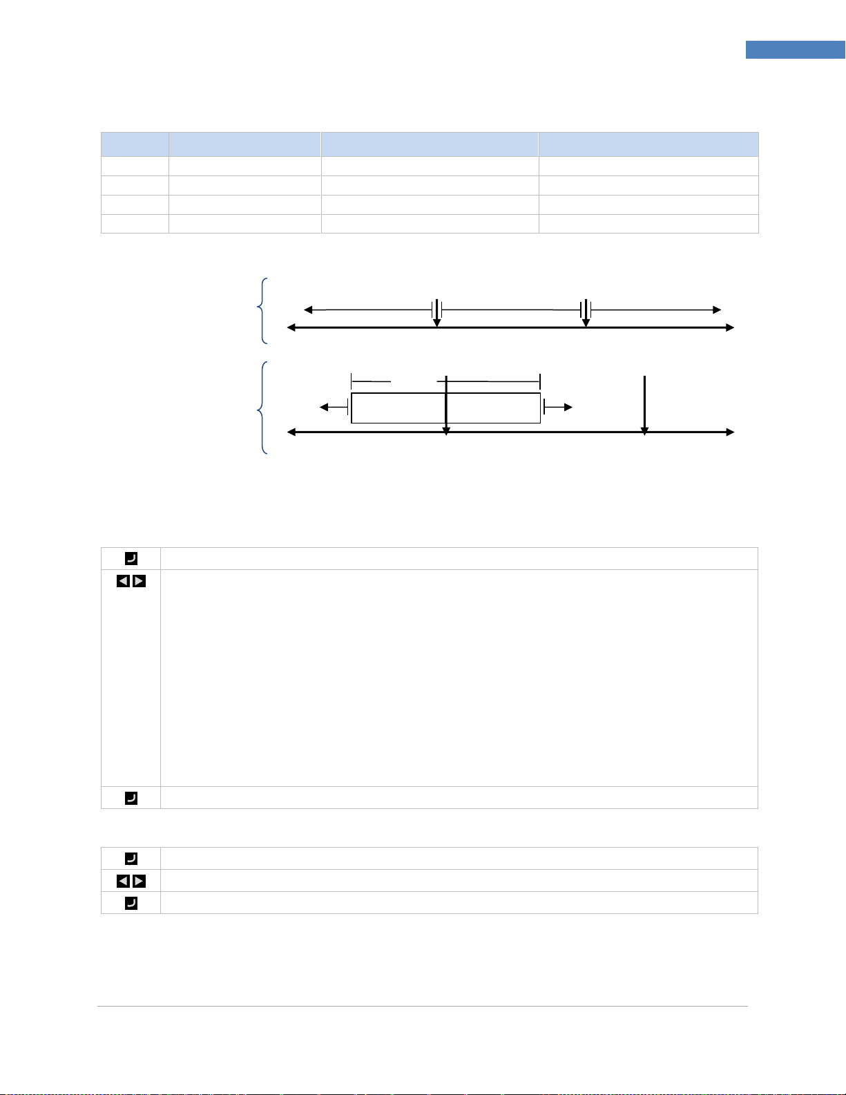
PLATINUMTM Series Controllers User’s Guide
50
Reference Section: Programming Mode (PRoG)
Setting
Absolute (AbSo)
Deviation (d.SP1)
Deviation (d.SP2)
AboV
> ALR.H
> SP1 + ALR.H
> SP2 + ALR.H
bELo
< ALR.L
< SP1 - ALR.L
< SP2 - ALR.L
HI.Lo.
< ALR.L or > ALR.H
< SP1 - ALR.L or > SP1 + ALR.H
< SP2 - ALR.L or > SP2 + ALR.H
bANd
> ALR.L and < ALR.H
> SP1 - ALR.L and < SP1 + ALR.H
> SP2 - ALR.L and < SP2 + ALR.H
Select the Absolute or Deviation Alarm (Ab.dV) parameter.
Navigate to the correct setting. Settings and sub settings include the following:
AbSo – Alarm is triggered using calculations based on the absolute values of ALR.H
or ALR.L used as specified by the tyPE parameter
d.SP1 – Alarm is triggered using calculations based on values relative to SP1 as
specified by the tyPE parameter
d.SP2 – Alarm is triggered using calculations based on values relative to SP2 as
specified by the tyPE parameter.
CN.SP – Alarm is triggered using calculations based on values relative to
instantaneous control setpoint generated by Ramp & Soak as specified by the tyPE
parameter.
Select the desired setting.
Select the Alarm High Reference (ALR.H) parameter.
Set the Alarm High Reference value.
Confirm the value.
bANd
AboV, HI.Lo.
bELo, HI.Lo.
Higher
Lower
ALR.L
ALR.H
(SP2 has the same
alarm options.)
SP1
SP2
bANd
Higher
Lower
ALR.L
bELo, HI.Lo.
ALR.H
AboV, HI.Lo.
Table 7 – Alarm Range Option Comparison
Absolute Mode (AbSo)
Deviation Mode (dEVI)
Figure 10 – Alarm Range Option Diagram
7.3.2 Absolute or Deviation Alarm (PRoG > ALM.1, ALM.2 > tyPE >
Ab.dV)
7.3.3 Alarm High Reference (PRoG > ALM.1, ALM.2 > tyPE > ALR.H)
M5451 Omega Engineering | www.omega.com
Page 51
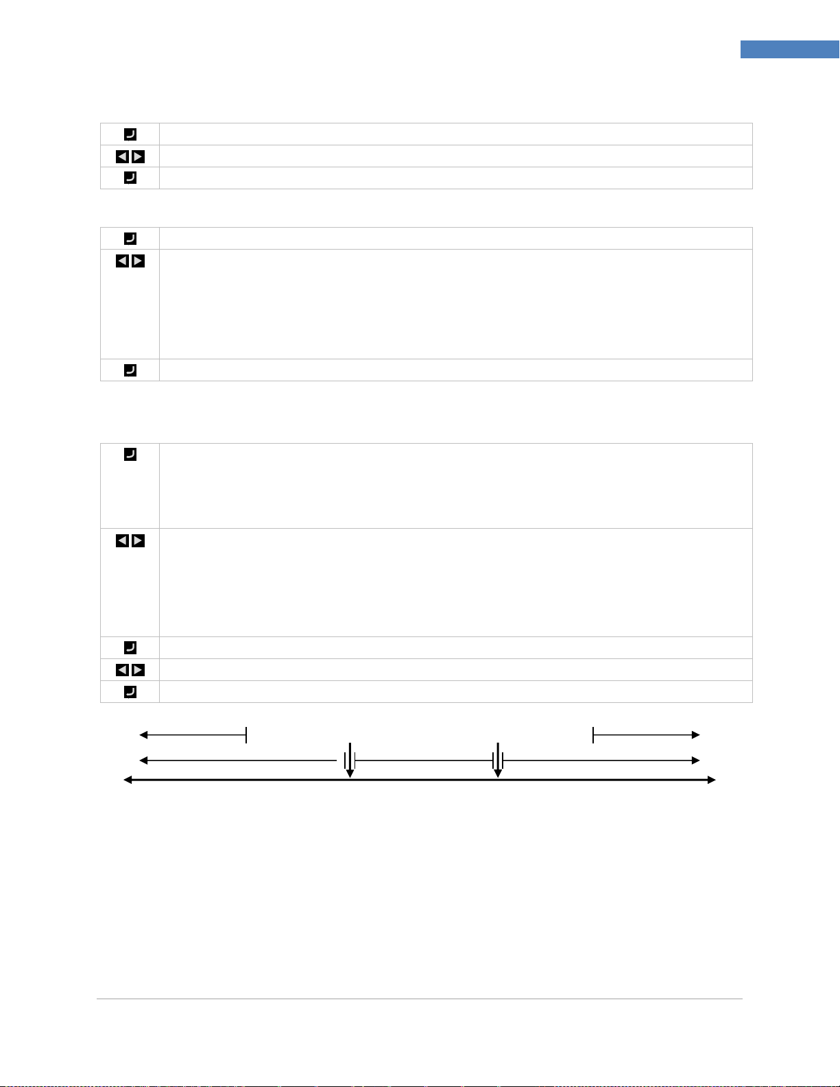
PLATINUMTM Series Controllers User’s Guide
51
Reference Section: Programming Mode (PRoG)
Select the Alarm Low Reference (ALR.L) parameter.
Set the Alarm Low Reference value.
Confirm the value.
Select the Alarm Color (A.CLR) parameter.
Navigate to the desired option. Options include the following:
REd – Alarm conditions are displayed in red (factory default)
AMbR – Alarm conditions are displayed in amber
GRN – Alarms conditions are displayed in green
dEFt – Alarms do not affect the default display color
Select the desired option.
Select the Alarm Offset Value (HI.HI) parameter. This parameter allows an offset to be added
to the Alarm trigger point(s) which will flash the display when exceeded. Depending on the
Alarm type the offset can apply above the trigger point, below it, or both. This is illustrated in
Figure 5.2. HI.HI works with both absolute and deviation Alarms.
Navigate to the correct option. Options include the following:
oFF – High High / Low Low function disabled (factory default)
oN – Display will flash in the color determined by the A.CLR parameter when the
Process Value is greater than the HI.HI offset value away from the Alarm condition
settings (in either direction)
Select the indicated option.
For oN, set the offset value.
Confirm the value.
Higher
Lower
bANd
AboV, HI.Lo.
bELo, HI.Lo.
ALR.L
ALR.H
Lo.Lo
HI.HI
7.3.4 Alarm Low Reference (PRoG > ALM.1, ALM.2 > tyPE > ALR.L)
7.3.5 Alarm Color (PRoG > ALM.1, ALM.2 > A.CLR)
7.3.6 Alarm High High / Low Low Offset Value (PRoG > ALM.1, ALM.2 >
HI.HI)
Figure 11 – Alarm HI.HI parameter.
M5451 Omega Engineering | www.omega.com
Page 52
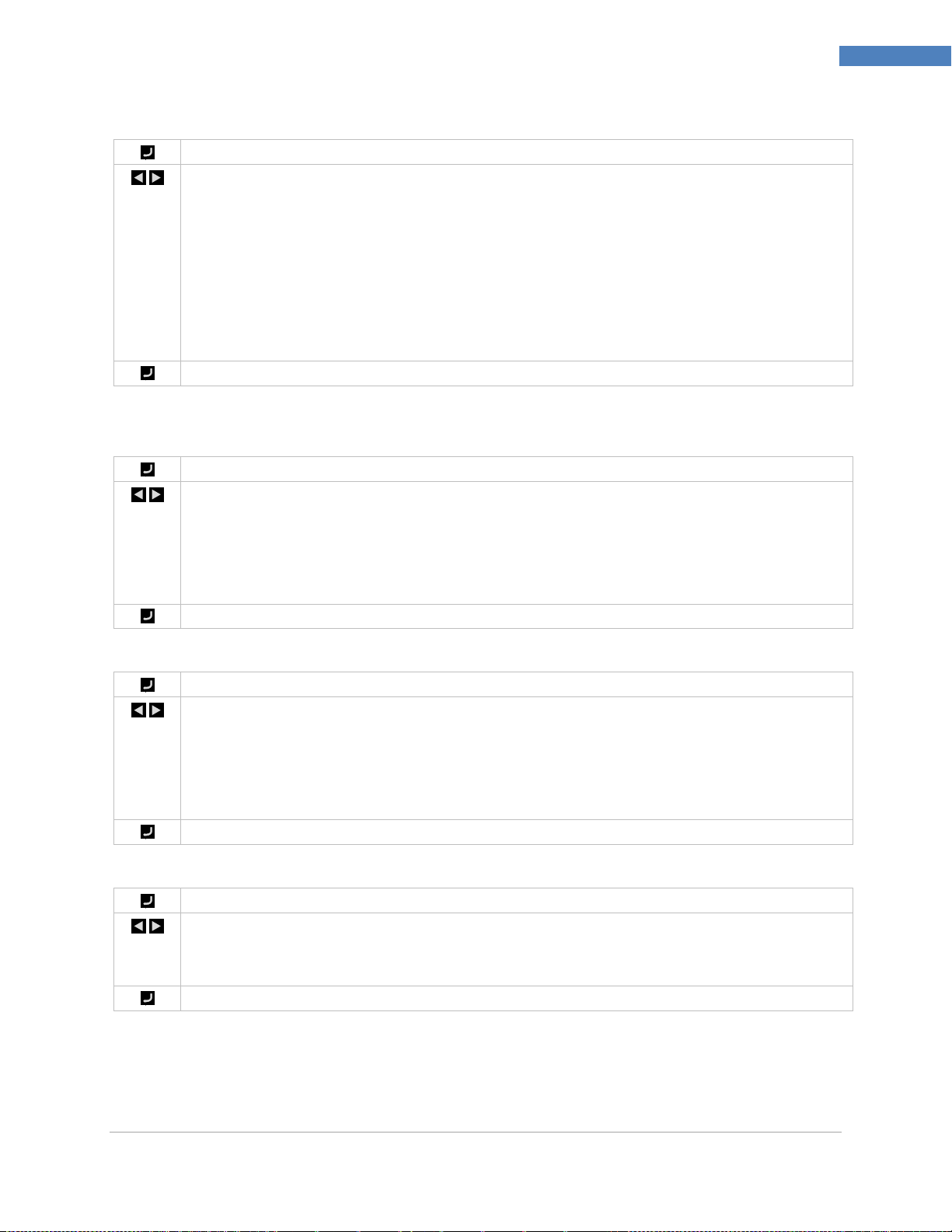
PLATINUMTM Series Controllers User’s Guide
52
Reference Section: Programming Mode (PRoG)
Select the Alarm Latching (LtCH) parameter.
Navigate to the desired option. Options include the following:
No – Alarm does not latch (factory default); the Alarm turns off when the Process
Value returns to a non-Alarm condition
yES – Alarm latches; even if the Process Value returns to a non-Alarm condition, the
Alarm condition remains active and must be unlatched using oPER > L.RSt
botH – Alarm latches and can be unlatched either by using oPER > L.RSt from the front
panel or via the digital input
RMt – Alarm latches and can be unlatched only via the digital input
Select the indicated option.
Select the Alarm Normally Open or Normally Closed (CtCL) parameter.
Navigate to the desired option. Options include the following:
N.o. – Normally open: output is activated when the Alarm condition is met (factory
default)
N.C. – Normally closed: output is activated in normal conditions, but turned off in
the Alarm condition
Select the indicated option.
Select the Alarm Power-On Behavior (A.P.oN) parameter.
Navigate to the desired option. Option include:
yES – Alarms are active at power-on and do not require crossing the Setpoint
(factory default)
No – Alarms are inactive at power-on; the process reading must cross the Alarm
condition before being activated
Select the indicated option.
Select the Alarm On Delay (dE.oN) parameter.
Set the number of seconds to delay triggering the Alarm. (The default is 0.) This setting can be
used to prevent false Alarm triggering when the Process Value only briefly enters an Alarm
condition.
Confirm the value.
7.3.7 Alarm Latching (PRoG > ALM.1, ALM.2 > LtCH)
7.3.8 Alarm Normally Closed, Normally Open (PRoG > ALM.1, ALM.2 >
CtCL)
7.3.9 Alarm Power-On Behavior (PRoG > ALM.1, ALM.2 > A.P.oN)
7.3.10 Alarm on Delay (PRoG > ALM.1, ALM.2 > dE.oN)
M5451 Omega Engineering | www.omega.com
Page 53

PLATINUMTM Series Controllers User’s Guide
53
Reference Section: Programming Mode (PRoG)
Select the Alarm Off Delay (dE.oF) parameter.
Set the number of seconds to delay cancelling the Alarm. (The default is 0.) This setting can be
used to prevent Alarm chatter.
Confirm the value.
Navigate to the desired output channel. The number and type of output channels on the
PLATINUMTM Series are automatically recognized by the device. The following output names
display, replacing the generic oUt.1 through oUt.6 references used in this document:
StR1 – Single Throw Mechanical Relay number 1
StR2 – Single Throw Mechanical Relay number 2
StR3 – Single Throw Mechanical Relay number 3
StR4 – Single Throw Mechanical Relay number 4
dtR1 – Double Throw Mechanical Relay number 1
dtR2 – Double Throw Mechanical Relay number 2
SSR1 – Solid State Relay number 1
SSR2 – Solid State Relay number 2
SSR3 – Solid State Relay number 3
SSR4 – Solid State Relay number 4
dC1 – DC Pulse output number 1
dC2 – DC Pulse output number 2
dC3 – DC Pulse output number 3
ANG1 – Analog output number 1
IdC1 – Isolated DC Pulse output number 1
IdC2 – Isolated DC Pulse output number 2
IAN1 – Isolated Analog output number 1
Note: All output channels have the same menu structure. However, only those parameters
that apply for the type of output being configured appear in that output’s menu.
Select the indicated output channel.
Navigate to the desired submenu. Submenus include the following:
ModE – Allows the output to be set up as a control, Alarm, retransmission, or
Ramp/Soak event output; the output can also be turned off
CyCL – PWM pulse width setting for DC pulse, mechanical relay, and solid state
relay outputs
RNGE – Sets the voltage or current range for analog outputs
Select the indicated setting.
7.3.11 Alarm Off Delay (PRoG > ALM.1, ALM.2 > dE.oF)
7.4 Output Channel 1–6 Configuration (PRoG > oUt.1–oUt.6)
M5451 Omega Engineering | www.omega.com
Page 54
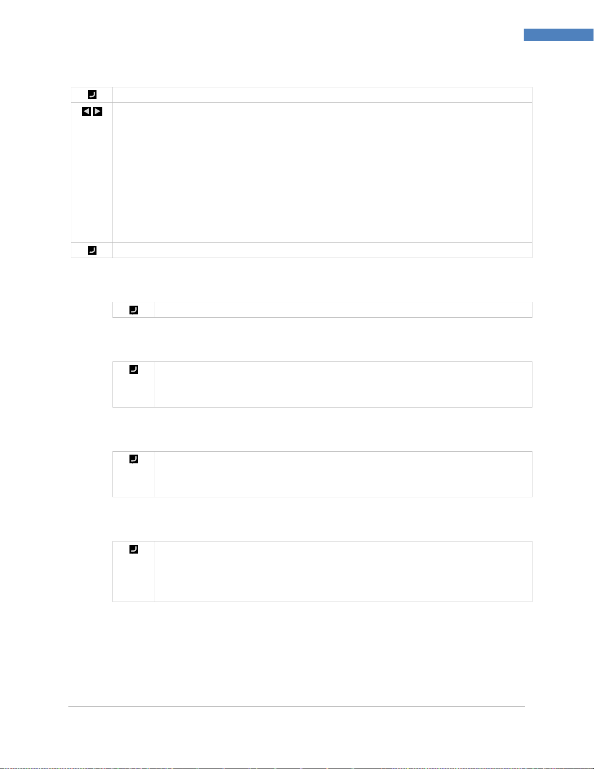
PLATINUMTM Series Controllers User’s Guide
54
Reference Section: Programming Mode (PRoG)
Select Output Channel Mode (ModE) to configure the specified output.
Navigate to the desired setting. Settings include the following:
oFF – Turn off the output channel (factory default)
PId – Set the output to Proportional-Integral-Derivative (PID) Control Mode
oN.oF – Set the output to On/Off Control Mode
ALM.1 – Set the output to be an Alarm using the ALM.1 configuration
ALM.2 – Set the output to be an Alarm using the ALM.2 configuration
RtRN – Set up the output for Retransmission
RE.oN – Turn on the output during Ramp events
SE.oN – Turn on the output during Soak events
Select the indicated setting.
Turn off this output (oFF).
Select PID Control Mode (PId) for this output (factory default). PID parameters are
set outside the specific output submenus, as more than one output can be used for
PID control at a time. See 7.5 PID Configuration (PRoG > PID).
Select PID Control Mode (PId.2) for this output. PID.2 parameters are set outside
the specific output submenus, as more than one output can be used for PID.2
control at a time. See 7.5 PID Configuration (PRoG > PID).
Select On/Off Control Mode (oN.oF) for this output. More than one output can be
set up for oN.oF control. For Heat / Cool control set the output connected to the
heater with ACtN equal to RVRS and the output connected to the cooling device
with ACtN set to dRCt.
7.4.1 Output Channel Mode (PRoG > oUt1–oUt6 > ModE)
7.4.1.1 Turn Off Output Channel (PRoG > oUt1–oUt6 >
ModE > oFF)
7.4.1.2 PID Control Mode (PRoG > oUt1–oUt6 > ModE >
PId)
7.4.1.3 PID 2 Control Mode (PRoG > oUt1–oUt6 > ModE
> PId.2)
7.4.1.4 On/Off Control Mode (PRoG > oUt1–oUt6 >
ModE > oN.oF)
M5451 Omega Engineering | www.omega.com
Page 55
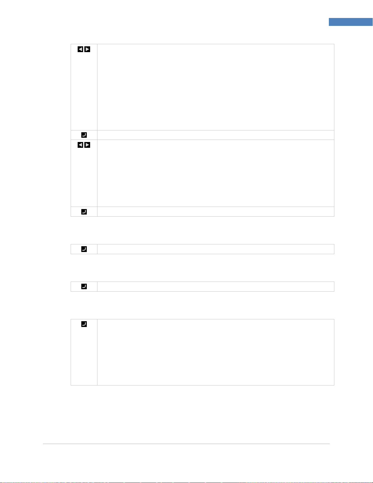
PLATINUMTM Series Controllers User’s Guide
55
Reference Section: Programming Mode (PRoG)
Navigate to the desired setting. Settings include the following:
ACtN – Determines the action direction for control
dEAd – Sets the deadband value; the deadband value is applied in the
same units as the process variable to one side of Setpoint as determined by
the ActN direction
S.PNt – Allows either Setpoint 1 or Setpoint 2 to be specified as the
target value; Setpoint 2 can be set to track Setpoint 1 using the deviation
(dEVI) option (7.2 Setpoint 2 (PRoG > SP2))—a useful feature when setting
up for heat/cool operation
Select the indicated setting.
For ACtN, select the correct setting. Settings include the following:
RVRS – Off when Process Value is > Setpoint, and on when Process Value
is < Setpoint (e.g., heating); deadband is applied below Setpoint (factory
default)
dRCt – Off when Process Value is < Setpoint, and on when Process Value
is > Setpoint (e.g., cooling); deadband is applied above Setpoint
For dEAd, set the desired value. (The default is 5.0.)
Select the indicated ACtN setting, or confirm the dEAd value.
Select this Output to be an Alarm using the Alarm 1 (ALM.1) configuration.
Select this Output to be an Alarm using the Alarm 2 (ALM.2) configuration.
Select Retransmission (RtRN) as the Operating Mode for the output. This option is
only available for analog outputs. Scaling is performed using absolute values—not
calculated counts. The retransmission signal type (voltage or current and range) is
set for this output using the 7.4.3 Analog Output Range (PRoG > oUt1–oUt6 > RNGE)
parameter. The retransmission signal is then scaled using the following 4
parameters. The unit will display the first scaling parameter, Rd1, after RtRN is
selected.
7.4.1.5 Output as Alarm 1 (PRoG > oUt1–oUt6 > ModE >
ALM.1)
7.4.1.6 Output as Alarm 2 (PRoG > oUt1–oUt6 > ModE >
ALM.2)
7.4.1.7 Retransmission (PRoG > oUt1–oUt6 > ModE >
RtRN)
M5451 Omega Engineering | www.omega.com
Page 56
PLATINUMTM Series Controllers User’s Guide
56
Reference Section: Programming Mode (PRoG)
Navigate to the desired setting. Settings include the following:
Rd1 – Process reading 1; the process reading that corresponds to the
output signal oUt1
oUt1 – The output signal that corresponds to the process value Rd1
Rd2 – Process reading 2; the process reading that corresponds to the
output signal oUt2
oUt2 – The output signal that corresponds to the process value Rd2
Select the indicated setting.
Set the desired value.
Confirm the value.
Activate Output to Ramp Event Mode (RE.oN) during Ramp segments in Ramp and
Soak programs when the Ramp Event flag is set for that Ramp segment. This can be
used to turn on auxiliary devices such as fans or stirrers, secondary heaters, etc.
Activate Output to Soak Event Mode (SE.oN) during Soak segments in Ramp and
Soak programs when the Soak Event flag is set for that Soak segment. This can be
used to turn on auxiliary devices such as fans or stirrers.
Activate Output to Sensor Error (SEN.E) Event Mode. The output will activate when
any sensor error is detected (i.e: open sensor, out of range, loop break). This can be
used to turn on an indicator or alarm to indicate the condition of sensor.
Activate Output to Open Loop Error (oPL.E) Event Mode. The output will activate
when output break is detected. See INIT > SFty > OUT.M for output monitor setup.
This can be used to turn on an indicator or alarm to indicate the condition of output
actuator.
Select the Output Cycle Pulse Width (CyCL) parameter. This parameter is used to set the
control signal pulse width in seconds for DC pulse, mechanical relay, and solid state relay
(SSR) outputs.
7.4.1.8 Set Output to Ramp Event Mode (PRoG > oUt1–
oUt6 > ModE > RE.oN)
7.4.1.9 Set Output to Soak Event Mode (PRoG > oUt1–
oUt6 > ModE > SE.oN)
7.4.1.10 Set Output to Sensor Error Event Mode (PRoG >
oUt1- oUt6 > ModE > SEN.E)
7.4.1.11 Set Output to Output Break Event Mode (PRoG >
oUt1 – oUt6 >ModE > O
7.4.2 Output Cycle Pulse Width (PRoG > oUt1–oUt6 > CyCL)
M5451 Omega Engineering | www.omega.com
Page 57
PLATINUMTM Series Controllers User’s Guide
57
Reference Section: Programming Mode (PRoG)
Set a value.
Note: For DC pulse and SSR outputs, choose a value between 0.1 and 199.0. (The default is
0.1s.) For mechanical relays, choose a value between 1.0 and 199.0. (The default is 5.0s.)
Confirm the value.
Select the Output Range (RNGE) parameter. This menu choice is only available for analog
outputs. The RNGE parameter is used for both Control and Retransmission Modes and
generally must be matched to the input range for whatever device the analog output is
driving.
Navigate to the desired setting. Settings include the following:
0–10 – 0 to 10 Volts (factory default)
0–5 – 0 to 5 Volts
0–20 – 0 to 20 mA
4–20 – 4 to 20 mA
0–24 – 0 to 24 mA
Select the desired range setting.
7.4.3 Analog Output Range (PRoG > oUt1–oUt6 > RNGE)
M5451 Omega Engineering | www.omega.com
Page 58
PLATINUMTM Series Controllers User’s Guide
58
Reference Section: Programming Mode (PRoG)
Select PId.S to configure the PID control settings. These settings apply to all outputs that have
had their Control Mode set to PID (7.4.1.2 PID Control Mode (PRoG > oUt1-oUt6 > ModE >
PId)). PID control can be optimized in a variety of ways. The suggested way is to initiate an
Autotune command (7.5.3 Autotune (PRoG > PId > AUto)) and then enable adaptive tuning
(7.5.7 Adaptive Tuning (PRoG > PId > AdPt)). The PID parameters may also be set manually or
manually adjusted after an Autotune command has been executed.
Navigate to the desired setting. Settings include the following:
ACtN – Action direction moves up or down to SP1
A.to – Autotuning Timeout sets a maximum amount of time for Autotuning
AUto – Initiates Autotuning
GAIN – Select the proportional, integral, and derivative factors for manual tuning
%Lo – Low clamping limit for Pulse and Analog outputs
%HI – High clamping limit for Pulse and Analog outputs
AdPt – Fuzzy logic adaptive tuning
Select the desired parameter.
Select the Direction (ACtN) parameter.
Navigate to the desired setting. Settings include the following:
RVRS – “Reverse Action”: Increase to SP1, such as heating (factory default)
dRCt – “Direct Action”: Decrease to SP1, such as cooling
RVRS/dRCt – Increase or Decrease to SP1, such as heating/cooling
Select the indicated setting.
Select the Autotune Timeout (A.to) parameter.
Set the amount of time before the Autotune process gives up and times out in Minutes and
Seconds (MM.SS). Slowly responding systems should have a longer time-out setting.
Select the indicated setting.
Select the Autotune (AUto) command. The unit displays StRt.
Confirm Autotune activation. The unit attempts to optimize the P, I, and d settings by
stimulating the system and measuring the response. If the A.to time out period expires before
the Autotune operation can complete, the unit displays a failure message E007. If the
Autotune operation completes successfully, the unit displays the message “doNE” and the
Run mode is switched to IDLE.
7.5 PID Configuration (PRoG > PId.S)
7.5.1 Action Response (PRoG > PId > ACtN)
7.5.2 Autotune Timeout (PRoG > PId > A.to)
7.5.3 Autotune (PRoG > PId > TUNE)
The Autotune function will select the tuning algorithm depending on the stability of current process and
the error difference between current process and the Control Setpoint (SP1). If the process is relatively
stable (i.e: at room temperature), a bump test will be performed to determine the plant characteristics.
M5451 Omega Engineering | www.omega.com
Page 59

PLATINUMTM Series Controllers User’s Guide
59
Reference Section: Programming Mode (PRoG)
Select Gain (GAIN) to manually adjust the PID factors. Setting I to zero sets the controller for
“PD” control, setting d to zero sets the controller for “PI” control, and setting both I and d to
zero sets the controller for “proportional” control. Most of the time use Autotune, and
adaptive tuning, and letting the system optimize its own PID factors. The P, I, and d factors
are used to calculate output power according to the following equation:
%On = P*e + I*SUM(e) + d*(de/dt)
%On = %Power for Analog Outputs or %On Width for PWM Outputs
e = Error Function = Setpoint – Process Value
SUM(e) = A summation of the Error Function over time
de/dt = The rate of change of the Error Function over time
The P, I, and d factors can initially be set using the Autotune function and then fine-tuned.
Time unit is in seconds.
Navigate to the desired manual parameter. Parameters include the following:
_P_ – Proportional Factor. The proportional factor amplifies the error function
(process value minus Setpoint) to accelerate progress towards to the Setpoint. (The
default value is 001.0.)
_I_ – Integral Factor. The integral term amplifies the integrated error function over
time and can increase the acceleration towards the Setpoint faster than the
Proportional factor (and potentially result in more “overshoot”). This factor is
sometimes referred to by its reciprocal, “Reset.”
_d_ – Derivative Factor. The derivative term (sometimes referred to by its
reciprocal, “Rate”) senses the rate of rise or fall of the input measurement and
throttles the PID algorithm accordingly. A higher value for this factor can speed up or
slow down the response of the system even faster than an increase in the Integral
Factor will.
Select the indicated setting.
Set the desired value.
Confirm the value.
If the process is hot, or if the process is within 10% of Control Setpoint, limit cycle oscillation will be
performed with the tuning setpoint taken at the process value when the Autotune function is triggered.
Autotuning may be performed as many times as needed or when the operating conditions (i.e: process
load, or setpoint) have changed significantly. To obtain good tuning results, ensure the process is stable
prior to triggering autotune function. The process is stable when it is at ambient temperature, or it is
tracking Control Setpoint (SP1) in auto mode.
7.5.4 PID Gain Settings (PRoG > PId > GAIN)
M5451 Omega Engineering | www.omega.com
Page 60
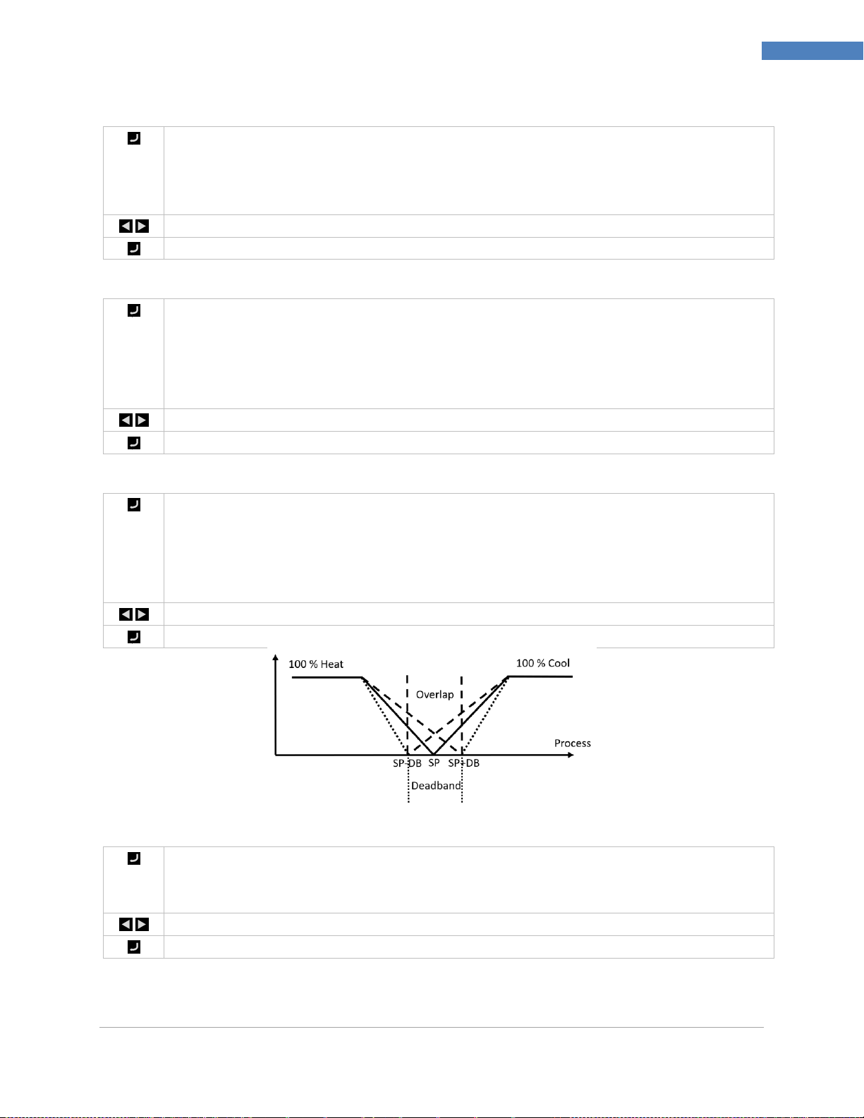
PLATINUMTM Series Controllers User’s Guide
60
Reference Section: Programming Mode (PRoG)
Select the Relative Cool Gain (rCg) parameter. The cooling output will be adjusted by this
multiplier. Valid only for Reverse/Direct (RVRS/dRCt ) control mode. Relative Cool Gain is
useful to restore heat/cool balance when heater and cooler of different power ratings are
used.
Set the desired value.
Confirm the value.
Select the Control Offset (oFst) parameter. Control Offset is a manual adjustment to the PID
output power. The parameter is effective when the PID output power is non-zero. Control
Offset is useful when the output power needs to start from a value other than zero (i.e: PWM
delivery to a motor fan)
%On = %PID + Offset
Set the desired value.
Confirm the value.
Select the Dead band/Overlap band (dEAd) parameter. A positive value sets a deadband and a
negative value sets an overlap band. Deadband parameter creates a band on both sides of
control setpoint in which the same output power is maintained. Overlap band parameter
creates a band on both sides of control setpoint in which both reverse and direct outputs that
are controlled by the same PID channel are activated.
Set the desired value.
Confirm the value.
Select the Low Output Clamping Limit (%Lo) parameter. This parameter sets the lower limit of
%Power applied to an analog output, or %On time for PWM (pulse width modulated) control
used with the other output types. (The default setting is -100.0%.)
Set the desired value.
Confirm the value.
7.5.5 Relative Cool Gain (PRoG > PId > rCg)
7.5.6 Control Offset (PRoG > PId > oFst)
7.5.7 Deadband (PRoG > PId > dEAd)
7.5.8 Low Output Clamping Limit (PRoG > PId > %Lo)
M5451 Omega Engineering | www.omega.com
Page 61

PLATINUMTM Series Controllers User’s Guide
61
Reference Section: Programming Mode (PRoG)
Select the High Output Clamping Limit (%HI) parameter. This parameter sets the upper limit
for %power to analog outputs or %on time for PWM control with the other output types. (The
default setting is 100.0%.)
Set the desired value.
Confirm the value.
Select the Adaptive Tuning (AdPt) parameter.
Navigate to the desired setting. When adaptive tuning is enabled, the PID parameters are
continually optimized based on the process input changes caused by the current output
control parameters. This is the easiest way to optimize the PID algorithm for a wide variety of
systems. Adaptive tuning minimizes overshoot and decreases settling time. Autotune is
recommended for setting up adaptive tuning feature.
Settings include the following:
ENbL – Enables fuzzy logic adaptive tuning (factory default)
dSbL – Disables fuzzy logic adaptive tuning
Select the indicated setting.
Note: PID.2 is an independent control channel with separate configuration parameters. Both
PID and PID.2 channels drive toward the same Control Setpoint. PID.2 channel is useful when
the process is being controlled by two actuators with completely different characteristics. To
minimize interactions between the two loops, consider adding a process deadband.
Select the Remote Setpoint Configuration (RM.SP) parameter.
Navigate to the desired setting. A remote signal can then be used to set and/or change the
Setpoint value using an analog input. This function can be used for a variety of applications
where direct access to the controller for Setpoint manipulation is a problem (hazardous
environments, lack of proximity, etc.). It can also be used to configure the controller in a
cascaded control scheme. Settings include the following:
oFF – Do not use a remote Setpoint (factory default)
oN – Remote Setpoint replaces Setpoint 1
Note: oFF has no sub-parameters, but oN requires scaling of the remote Setpoint input.
Select the indicated setting.
7.5.9 High Output Clamping Limit (PRoG > PId > %HI)
7.5.10 Adaptive Tuning (PRoG > PId > AdPt)
7.6 PID.2 Configuration (PRoG > PId.2)
7.7 Remote Setpoint Configuration (PRoG > RM.SP)
M5451 Omega Engineering | www.omega.com
Page 62
PLATINUMTM Series Controllers User’s Guide
62
Reference Section: Programming Mode (PRoG)
If oN, navigate to the desired input range. Options include the following:
4–20 – 4.00–20.00 mA input signal range
0–24 – 0.00–24.00 mA input signal range
0–10 – 0.00–10.00 V input signal range
0–1 – 0.00–1.00 V input signal range
Select the desired input signal range to proceed to the scaling parameters starting with RS.Lo.
Navigate to the desired setting. Settings include the following:
RS.Lo – Minimum Setpoint value (entry point). Setpoint 1 is set to this value when
the analog input signal is IN.Lo.
IN.Lo – Input value in mA or V for RS.Lo
RS.HI – Maximum Setpoint value. Setpoint 1 is set to this value when the analog
input signal is IN.HI.
IN.HI – Input value in mA or V for RS.HI
Select the indicated setting.
Set the desired value.
Confirm the value.
M5451 Omega Engineering | www.omega.com
Page 63
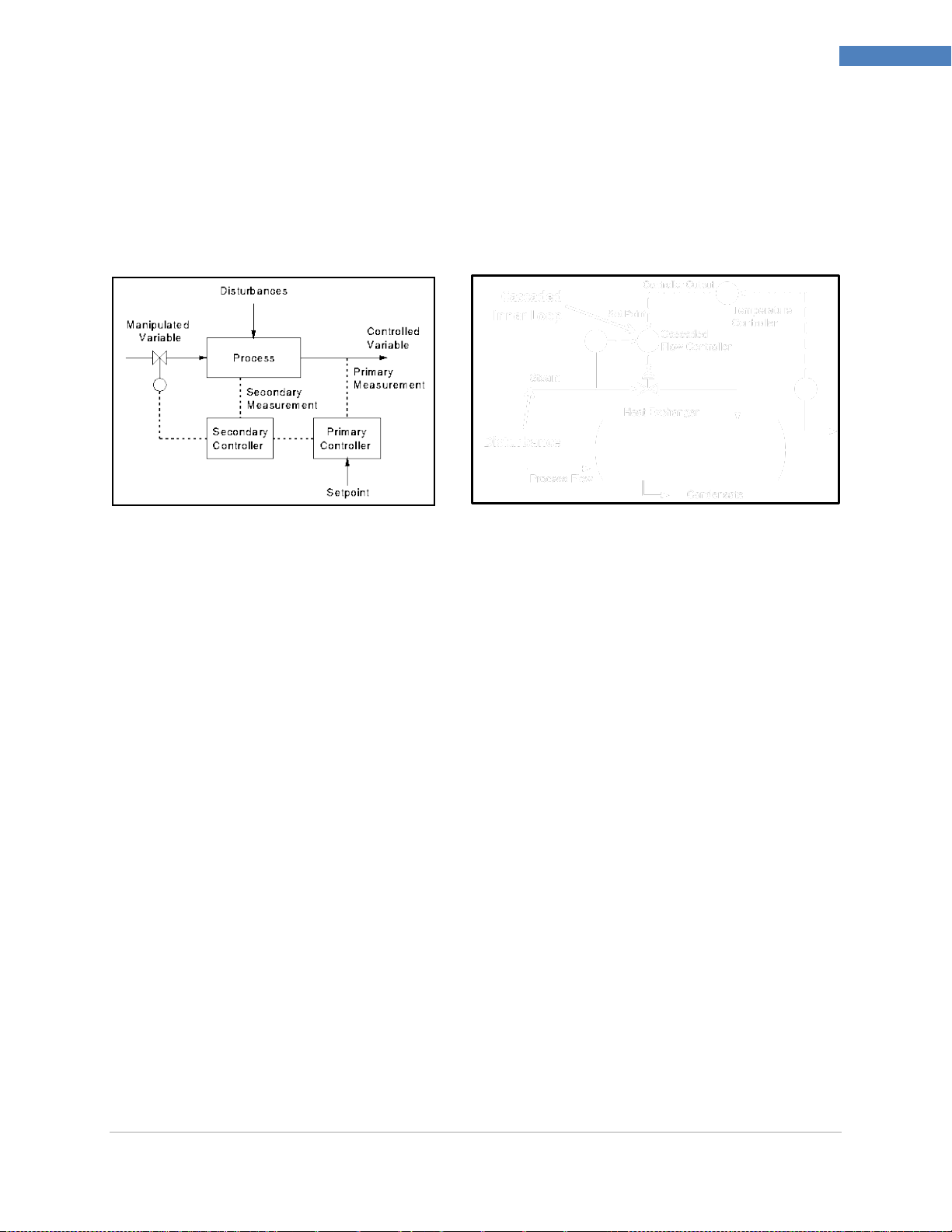
PLATINUMTM Series Controllers User’s Guide
63
Reference Section: Programming Mode (PRoG)
7.7.1 Cascade Control using Remote Setpoint
The remote Setpoint feature of the PLATINUMTM Series controllers can be used in a variety of
applications where Setpoints can be sent to the controllers from remote devices such as a manual pots,
transmitters, computers, etc. This feature can also be used to set up a “cascade control” system, where
the remote Setpoint input is generated by another controller. Figure 12 shows a generic diagram of a
cascade control system and Figure 13 shows a typical example, in this case a heat exchanger application.
Figure 12 Generic Cascade Control Diagram Figure 13 Heat Exchanger with Cascade Control
Cascade control schemes provide tighter control of a process when there are two linked variables, one
of which has a much slower (typically 4X or more) response than the other. The slower responding
variable is used as the input to the primary or master controller, and the faster responding variable is
used as the input to the secondary or slave controller. The output of the primary controller is scaled to
be used as the Setpoint for the secondary controller.
In the heat exchanger application in Figure 13, the primary goal of the application is to control the
temperature of the effluent. Therefore, the desired effluent temperature becomes the Setpoint for the
primary controller, which is a temperature controller (TC). The process input for the temperature
controller is the measured temperature of the effluent (TT). The output of the temperature controller is
the flow Setpoint for the secondary controller, which is a flow controller (FC). The process input for the
secondary (flow) controller is the flow rate of the steam that is used to heat the process flow through
the heat exchanger (FT). The output of the secondary (flow) controller is a control signal for the
proportional valve controlling the flow of the steam.
By isolating the slowly changing effluent temperature control loop from the rapidly changing flow
control loop, a more predictable, robust, and tighter control scheme results.
M5451 Omega Engineering | www.omega.com
Page 64

PLATINUMTM Series Controllers User’s Guide
64
Reference Section: Programming Mode (PRoG)
Select Multi-Ramp/Soak Mode (M.RMP) for activation and configuration to store, and load up
to 99 Ramp/Soak programs. Each program can have up to 8 Ramps and 8 Soaks including the
ability to activate auxiliary (non-control) outputs during any or all Ramp and Soak segments.
Any segment soak setpoint can be an increase or a decrease from the previous soak setpoint
and the unit will automatically determine the control direction (reverse or direct) for the
associated ramp. The end action (E.Act) can be defined as StOP, HOLd, or LINk. By using
LINk, one program can be specified to start at the end of the previous program, creating an
absolute capability to set up a program with 8*99 or 792 ramps and 792 soaks. In addition, a
program can be linked to itself to create a continuously cycling profile.
Configuration settings files can be edited on a PC in Excel and this can be especially useful
when creating / editing complex ramp and soak programs. See 6.9 INIt > SAVE for further
information on this.
For an overview of Ramp and Soak programming including examples see Section 7.7.8 More
on Multi-Ramp/Soak Programming.
Note: When setting up multidirectional ramp and soak programs, only one direction can use
PID control as PID control is set to reverse (heating) or direct (cooling) action for any and all
outputs assigned to MoDE > PID. PID Autotuning of the system under control will tune only
for the PID action direction as the optimum PID parameters for the other action direction may
be completely different. On/Off control must be used to set up any output(s) for the other
action direction.
Navigate to the desired setting. Settings include the following:
R.CtL – Activate Multi-Ramp/Soak Mode
S.PRG – Program number
M.tRk – Multi-Ramp/Soak tracking setting
tIM.F – Time format for Ramp/Soak programs
N.SEG – Number of segments
S.SEG – Segment number for editing
E.Act – Determines what happens at the end of a program
Select the indicated setting.
Select the Multi-Ramp/Soak Mode Control (R.CtL) parameter.
Navigate to the desired setting. Settings include the following:
No – Multi-Ramp/Soak Mode off
yES – Multi-Ramp/Soak Mode on; must be started from front panel
RMt – Multi-Ramp/Soak Mode on; front panel or digital input to start
Select the indicated setting.
7.8 Multi-Ramp/Soak Mode Parameters (PRoG > M.RMP)
M5451 Omega Engineering | www.omega.com
7.8.1 Multi-Ramp/Soak Mode Control (PRoG > M.RMP > R.CtL)
Page 65
PLATINUMTM Series Controllers User’s Guide
65
Reference Section: Programming Mode (PRoG)
Select the Select Program (S.PRG) parameter. The current profile for the selected program
number will be loaded and can be used as is or modified.
Set the number (1–99) corresponding to the Ramp/Soak profile to be loaded for use or
editing. (The default is 1)
Confirm the value.
Select the Multi-Ramp/Soak Tracking (M.tRk) parameter. This parameter has three settings
that allow for different ways to manage ramp and soak program tracking.
Navigate to the desired setting. Settings include the following:
RAMP – Guaranteed Ramp Mode. If the soak setpoint is not reached within the
specified Ramp Time, the Ramp and Soak cycle will terminate, the outputs are
disabled, and a failure message (E008) will be displayed.
SoAK – Guaranteed Soak Mode. If the soak setpoint is not reached within the
specified Ramp Time the system will continue to Ramp and not transition to the Soak
Mode until the Soak point is reached. The full specified Soak time is preserved.
CYCL – Guaranteed Cycle Mode. If the soak setpoint is not reached within the
specified Ramp Time, the unit will continue to ramp until that setpoint is reached.
The additional ramp time required is subtracted from the soak time so that the
specified cycle time (ramp time + soak time) is preserved. If the soak setpoint is still
not reached at the end of total cycle time, the ramp and soak program will terminate,
the outputs are disabled, and the failure message (E0008) will be displayed.
Select the indicated setting.
Select the default Ramp and Soak Time Format (tIM.F) parameter for the current program.
The default format can be overridden to create mixed time mode Ramp and Soak programs.
NOTE: The time format option does not appear in 6 digit display units, which always show
time as HH:MM:SS
Navigate to the desired setting. Settings include the following:
MM.SS – Time specified in minutes and seconds (factory default)
HH.MM – Time specified in hours and minutes. Indicated by turning on the
negative sign to differentiate from MM.SS format when adjusting the MRT.# and
MST.# parameters for a given segment.
Select the indicated option. Note that the default time format can be overridden for any
given segment time by pressing the left arrow with that time showing until it sequences
through each digit and then the entire time flashes. Pressing the right arrow at that point will
change the setting for that segment to the other time format.
7.8.2 Select Program (PRoG > M.RMP > S.PRG)
7.8.3 Multi-Ramp/Soak Tracking (PRoG > M.RMP > M.tRk)
7.8.4 Time Format (PRoG > M.RMP > tIM.F)
M5451 Omega Engineering | www.omega.com
Page 66

PLATINUMTM Series Controllers User’s Guide
66
Reference Section: Programming Mode (PRoG)
Select the End Action (E.ACT) parameter.
Navigate to the desired setting. Settings include the following:
StOP – Enter standby mode displaying RUN at the completion of this program.
HOLd – Hold at the final soak setpoint at the completion of this program.
LINk – Link to another stored ramp & soak program at the completion of this
program.
o ## – Specify the Program Number to start at the completion of this
program (1 to 99). Specifying 0 will repeat the program specified by S.PRG
which can provide for cycling through a series of linked programs. Specifying
100 will restart the last program run in a sequence of linked programs.
Select the indicated setting.
Select the Number of Segments (N.SEG) parameter.
Set the number of segments (1–8). (The default is 1.)
Confirm the value.
Select the Segment Number for Editing (S.SEG).
Set the segment number to edit for the Program Number. This segment number selection will
replace the “#” digit in all of the ramp and soak control parameters for that segment listed
below (MRt.#, MSt.#, etc.), as viewed on the unit’s display. This will help keep track when
programming multiple ramp and soak segments from the front panel.
Confirm the segment number.
Navigate to the desired setting. Settings include the following:
MRt.# – Time for Ramp number # (the default is 10). Ramp and Soak times can be
as long as either 99 minutes and 59 seconds or 99 hours and 59 minutes. The default
format is controlled by the tIM.F parameter setting for this program. The default can
be overridden for any segment time as described under tIM.F.
MRE.# – Determine whether to activate Ramp-event-enabled outputs:
o oFF – Disable Ramp events for this segment (factory default)
o oN – Enable Ramp events for this segment. At least one output must be set
to MoDE = RE.oN for an enabled ramp event to actually do anything.
MSP.# – Setpoint value for Soak cycle #
MSt.# – Time for the Soak cycle (the default is 10). See MRT.# for more info.
MSE.# – Determine whether to activate Soak-event-enabled outputs:
o oFF – Disable Soak events for this segment (factory default)
o oN – Enable Soak events for this segment. At least one output must be set
to MoDE = RE.oF for an enabled soak event to actually do anything.
Select the indicated setting.
7.8.5 Program End Action (PRoG > M.RMP > E.ACT)
7.8.6 Number of Segments (PRoG > M.RMP > N.SEG)
7.8.7 Segment Number for Editing (PRoG > M.RMP > S.SEG)
M5451 Omega Engineering | www.omega.com
Page 67
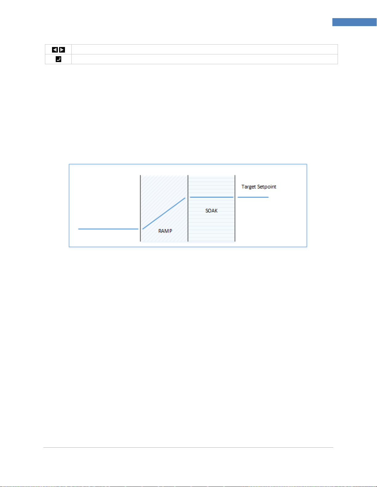
PLATINUMTM Series Controllers User’s Guide
67
Reference Section: Programming Mode (PRoG)
Navigate to the correct setting, or set the desired value.
Select the indicated setting, or confirm the value.
7.8.8 More on Multi-Ramp/Soak Programming
7.8.8.1 Overview
A key feature of the Ramp and Soak mechanism is provided by the ability to ‘link’ ramp/soak segments
together to create a chain of sequences. This allows sequences of up to 792 Ramp/Soak pairs to be
defined. A Ramp/Soak segment is defined as a specified increase or decrease (Ramp) of the process
variable over a set period of time, followed by holding (Soak) the process variable at a fixed level for a
fixed period of time.
Figure 14. Ramp & Soak Process Variable Period of Time.
M5451 Omega Engineering | www.omega.com
Page 68

PLATINUMTM Series Controllers User’s Guide
68
Reference Section: Programming Mode (PRoG)
LINK parameter
N
Where N is the number of
the current program
Allows continuous cycling of a single program
0
Reload the S.PRG program
Allows continuous process cycling using
multiple linked programs
1..99
Load the specified program
Allows linking to a specified program
100
Reload the current program
Allows cycling of the last program in a linked
chain of programs
These controllers provide a multi-segment/multi-profile Ramp and Soak mechanism with the additional
ability to link multiple profiles together to implement extended sequences.
Although the term ‘RAMP’ is used to indicate the process variable change, there is no restrictions on the
direction of change. The Target Setpoint may be above or below the Current process variable for each
cycle within a sequence.
Figure 15. Ramp & Soak Current Process Variable.
The Ramp and Soak times are provided in 1-second increments and may span from 1 second to 99
hours, 59 minutes, 59 seconds. Internally, the time values are tracked within 0.1 second intervals.
The Ramp and Soak function attempts to provide a controlled increase to the process variable such that
the target setpoint is reached within the specified time. Options are provided to track the specified
RAMP time, the specified SOAK time or the overall CYCLE time.
7.8.8.2 Ramp / Soak Program Linking
M5451 Omega Engineering | www.omega.com
Page 69

PLATINUMTM Series Controllers User’s Guide
69
Reference Section: Operating Mode (oPER)
Select Normal Run Mode (RUN). The ENTER button starts the unit operating according to the
current input, output, and communications settings. Run Mode will automatically be entered
and activated at unit power-on if the Power on Confirmation (6.7.1 Power On Confirmation
(INIt > SFty > PwoN)) parameter is set to dSbL. The process value is displayed in the main
display, and if the unit uses dual displays, the current Setpoint value is displayed in the
secondary display. With the unit remaining active, the oPER menu selections can be navigated
to using the LEFT and RIGHT buttons.
Select the Change Setpoint 1 (SP1) parameter. This function allows Setpoint 1 to be changed
while remaining in Run Mode. Pressing the ENTER button after changing a Setpoint while in
RUN Mode returns to RUN Mode with no interruption in monitoring, control, or
communications operations. If remote Setpoint is enabled, Setpoint 1 cannot be changed
here and the display will flash.
Set the desired value for Setpoint 1. When changing the Setpoints from the operating mode
menu, the left arrow decreases the value with acceleration and the right arrow increases the
value with acceleration. This is different from the decimal place switching numeric change
control in other places as changes made here are usually limited.
Confirm the value.
8. Reference Section: Operating Mode (oPER)
Operating Mode is used to activate the unit’s monitoring and controlling functions. It also allows
shortcut access to the Setpoint parameters while still running. Use Operating Mode to set the following
parameters and perform the following functions:
8. Reference Section: Operating Mode (oPER) ....................................................................................... 69
8.1 Normal Run Mode (oPER > RUN) ................................................................................................ 69
8.2 Change Setpoint 1 (oPER > SP1) .................................................................................................. 69
8.3 Change Setpoint 2 (oPER > SP2) .................................................................................................. 70
8.4 Manual Mode (oPER > MANL) .................................................................................................... 70
8.5 Pause Mode (oPER > PAUS) ........................................................................................................ 71
8.6 Stop Process (oPER > StoP) ......................................................................................................... 71
8.7 Clear Latched Alarms (oPER > L.RSt) ........................................................................................... 71
8.8 Display Valley Reading (oPER > VALy) ......................................................................................... 71
8.9 Display Peak Reading (oPER > PEAk) ........................................................................................... 72
8.10 Standby Mode (oPER > Stby) ...................................................................................................... 72
8.11 Standby Mode (oPER > tARE) ...................................................................................................... 72
8.1 Normal Run Mode (oPER > RUN)
8.2 Change Setpoint 1 (oPER > SP1)
M5451 Omega Engineering | www.omega.com
Page 70
PLATINUMTM Series Controllers User’s Guide
70
Reference Section: Operating Mode (oPER)
Select the Change Setpoint 2 (SP2) parameter. This function allows Setpoint 2 to be changed
while remaining in RUN Mode. The current value for Setpoint 2 flashes in the main display.
Setpoint 2 is only used for Alarms and as the cooling Setpoint in Heat/Cool Control Mode. See
7.1 Change Setpoint 1 (oPER > SP1) for additional information.
Set the desired value for Setpoint 2.
Confirm the value.
Select the Manual Operating Mode (MANL). This mode allows for control output levels or the
process input value to be manually changed.
Navigate to the desired Manual Operating Mode. The choices are as follows:
M.CNt – Manually vary the control output(s)
M.INP – Manually simulate change in the process input
Select the desired Manual Operating Mode.
Vary the Output or Input manually with the left and right arrows.
For M.CNt, the % On value is displayed instead of the process input value. With analog
outputs, the % On value specifies the output current or voltage as a percentage of the total
scaled range. With DC Pulse and Relay outputs, the % On value controls the width of the PWM
(pulse-width modulated) signal.
For M.INP, the process input value continues to be displayed but the value can be changed up
or down using the RIGHT and LEFT buttons, respectively. This is a “simulated value” and it can
be used to test out Alarm configurations, retransmission scaling, etc.
Exit Manual Mode and return to Run Mode.
8.3 Change Setpoint 2 (oPER > SP2)
8.4 Manual Mode (oPER > MANL)
M5451 Omega Engineering | www.omega.com
Page 71
PLATINUMTM Series Controllers User’s Guide
71
Reference Section: Operating Mode (oPER)
Select the Pause Operating Mode (PAUS) to pause the controller and hold the process input
at its current value. If in a Multi-Ramp/Soak program, the timer for the current Ramp or Soak
segment is paused as well. The current process value display will flash while in pause mode.
Return to RUN Mode or to displaying “RUN” depending on the Operating Safety parameter
setting (6.7.2 Operating Mode Confirmation (INIt > SFty > oPER)).
Select the Stop Operating Mode (StoP) to turn off all control outputs. The current process
value remains with flashing digits in this mode. Alarm conditions are maintained.
Return to RUN Mode or to displaying “RUN” depending on the Operating Safety parameter
setting (6.7.2 Operating Mode Confirmation (INIt > SFty > oPER)).
Select the Clear Latched Alarms command (L.RSt) to clear currently latched Alarms.
Alternatively, use digital input to activate the L.RSt command if configured in the PRoG menu
as explained in 7.3.7 Alarm Latching (PRoG > ALM.1, ALM.2 > LtCH).
Return to RUN Mode or to displaying “RUN” depending on the Operating Safety parameter
setting (6.7.2 Operating Mode Confirmation (INIt > SFty > oPER)).
Select Display Valley Reading (VALy) to change the process value displayed to the lowest
reading since VALy was last cleared.
Clear the VALy reading buffer. Return to RUN Mode or to displaying “RUN” depending on the
Operating Safety parameter setting (6.7.2 Operating Mode Confirmation (INIt > SFty > oPER)).
Note: Using the other buttons to navigate away from VALy does not clear the VALy reading
buffer.
8.5 Pause Mode (oPER > PAUS)
8.6 Stop Process (oPER > StoP)
8.7 Clear Latched Alarms (oPER > L.RSt)
8.8 Display Valley Reading (oPER > VALy)
M5451 Omega Engineering | www.omega.com
Page 72
PLATINUMTM Series Controllers User’s Guide
72
Reference Section: Operating Mode (oPER)
Select Display Peak Reading (PEAk) to change the process value displayed to the highest
reading since PEAk was last cleared.
Clear the PEAk reading buffer. Return to RUN Mode or to displaying “RUN” depending on the
Operating Safety parameter setting (6.7.2 Operating Mode Confirmation (INIt > SFty > oPER)).
Note: Using the other buttons to navigate away from PEAk does not clear the PEAk reading
buffer.
Select Standby Mode (Stby) to disable outputs and Alarm conditions. Stby is displayed until
navigating elsewhere. Navigate to any desired initialization or programming settings to
change them or to adjust the process.
Return to RUN Mode or to displaying “RUN” depending on the Operating Safety parameter
setting (6.7.2 Operating Mode Confirmation (INIt > SFty > oPER)).
Select Standby Mode (tARE) to allow zeroing the current input value. Available only if enabled
in the INIt menu. The tARE will adjust the input offset to show zero.
Return to RUN Mode or to displaying “RUN” depending on the Operating Safety parameter
setting (6.7.2 Operating Mode Confirmation (INIt > SFty > oPER)).
8.9 Display Peak Reading (oPER > PEAk)
8.10 Standby Mode (oPER > Stby)
8.11 Standby Mode (oPER > tARE)
M5451 Omega Engineering | www.omega.com
Page 73

PLATINUMTM Series Controllers User’s Guide
73
Specifications
Input Types
Thermocouple, RTD, Thermistor, Analog Voltage, Analog Current
Current Input
4 to 20 mA, 0 to 24 mA Scalable
Voltage Input
-50 to + 50 mV, -100 to 100 mV, -1 to 1 V, -10 to 10 Vdc Single Ended Scalable
+/- 50 and +/- 100 mV differential and ratiometric inputs, scalable
Thermocouple Input
(ITS 90)
K, J, T, E, R, S, B, C, N
RTD Input (ITS 90)
100/500/1000 Ω Pt sensor, 2-, 3- or 4-wire; 0.00385 (100 Ω only), 0.00392
(100 Ω only), or 0.003916 (100 Ω only) curves
Configuration
Differential
Polarity
Bipolar
Accuracy
Refer to Table 8
Resolution
0.1°F/°C temperature; 10 µV process
Input Impedances
Process Voltage: 10 MΩ for +/- 100 mV
Process Voltage: 1 MΩ for other voltage ranges
Process Current: 5 Ω
Thermocouple: 10 KΩ max
Temperature
Stability
RTD: 0.04°C/°C
TC at 25°C (77°F): 0.05°C/°C (cold junction compensation)
Process: 50 ppm/°C
A/D Conversion
24 bit Sigma Delta
Reading Rate
20 samples per second
Digital Filter
Programmable from 0.05 seconds (filter = 1) to 6.4 seconds (filter = 128)
CMRR
120 dB
Excitation
Firmware selectable (no jumpers to set) to 5, 10, 12, and 24 Vdc @ 25 mA
Setpoint Adjustment
-9999 to +9999 counts
Warm Up to Rated
Accuracy
30 min
Action
Reverse (heat), direct (cool), or heat / cool
Autotune
Operator initiated from front panel
Adaptive Tune
User selectable; fuzzy logic continuous PID tuning optimization
Control Modes
On/off or the following time/amplitude Proportional Control Modes:
selectable Manual or Auto PID, Proportional, Proportional with Integral,
Proportional with Derivative
Cycle Time
0.1–199 seconds
9. Specifications
9.1 Inputs
9.2 Control
M5451 Omega Engineering | www.omega.com
Page 74

PLATINUMTM Series Controllers User’s Guide
74
Specifications
Ramp and Soak
Up to 99 Saved Ramp and Soak programs
Up to 8 Ramp and 8 Soak segments with individually selectable
events per program
Definable End Actions include program linking
Ramp and Soak segment times: 00.00 to 99.59 (for HH:MM and
MM:SS)
Analog
Non-Isolated, Proportional 0–10 Vdc or 0–20 mA; 500 Ω max. Programmable
for control or retransmission. Accuracy is 0.1% of full scale.
DC Pulse
Non-Isolated; 10 Vdc at 20 mA
SPST Relay
Single pole, single throw mechanical relay, 250 Vac or 30 Vdc at 3 A (Resistive
Load)
SPDT Relay
Single pole, double throw mechanical relay, 250 Vac or 30 Vdc at 3 A
(Resistive Load)
SSR
20–265 Vac at 0.05–0.5 A (Resistive Load); continuous
Isolated DC Pulse
Isolated; 10 Vdc at 20 mA
Isolated Analog
Isolated, Proportional 0–10 Vdc or 0–20 mA; 500 Ω max. Programmable for
control or retransmission. Accuracy is 0.1% of full scale.
Connection
USB: Female Micro-USB, Ethernet: Standard RJ45, Serial: Screw terminals
USB
USB 2.0 Host or Device
Ethernet
Standards Compliance IEEE 802.3 10/100 Base-T Auto-switching, TCP/IP, ARP,
HTTPGET
Serial
Software Selectable RS/232 or RS/485. Programmable 1200 to 115.2 K baud.
Protocols
Omega ASCII, Modbus ASCII / RTU
Approvals
UL, C-UL, and CE (8. Approvals Information)
Power to
Input/Output
2300 Vac per 1 min test
1500 Vac per 1 min test (Low-Voltage/Power Option)
Power to Relays/SSR
Outputs
2300 Vac per 1 min test
Relays/SSR to
Relay/SSR Outputs
2300 Vac per 1 min test
RS-232/485 to
Inputs/Outputs
500 Vac per 1 min test
9.3 Outputs
9.4 Communications (USB Standard, Optional Serial and Ethernet)
9.5 Isolation
M5451 Omega Engineering | www.omega.com
Page 75

PLATINUMTM Series Controllers User’s Guide
75
Specificaons
Display
4-digit, 9-segment LED; red, green, and amber programmable colors for process
• 21 mm (0.83”) and 10.2 mm (0.40”): 8DPt (Dual Display)
Dimensions
• 8Pt Series: 48 H x 96 W x 127 mm D, (1.89 x 3.78 x 5")
• 32Pt Series: 25.4 H x 48 W x 127 mm D, (1.0 x 1.89 x 5")
Panel Cutout
• 32Pt Series: 22.5 H x 45 mm W (0.886" x 1.772"), 1/32 DIN
Environmental
All Models: 0–50°C (32–122°F), 90% RH non-condensing
External Fuse
Time-Delay, UL 248-14 listed:
400 mA/250 V (Low-Voltage Opon)
Line Voltage/Power
90–300 Vac +/-10%, 50-400 Hz1
• 5 W: power for 8DPt, 8EPt, 16DPt Models
Low-Voltage/Power
External power source must meet Safety Agency Approvals. Units can be
20–36 Vdc: 4 W power for 8DPt, 8EPt, 16DPt
Protecon
NEMA-4x/Type 4x/IP65 front bezel: 32Pt, 16Pt, 16DPt
• NEMA-1/Type 1 front bezel: 8Pt, 8DPt, 8EPt
Weight
• 8Pt Series: 295 g (0.65 lb)
32Pt Series: 127 g (0.28 lb)
9.6 General
variable, Setpoint, and temperature units
• 10.2 mm (0.40"): 32Pt, 16Pt, 16DPt (Dual Display)
• 21 mm (0.83"): 8Pt, 8EPt
• 16Pt Series: 48 H x 48 W x 127 mm D, (1.89 x 1.89 x 5")
8Pt Series: 45 H x 92 mm W (1.772" x 3.622"), 1/8 DIN
•
Condions
• 16Pt Series: 45 mm (1.772") square, 1/16 DIN
Required
Opon
• 100 mA/250 V
• 400 mA/250 V (Low-Voltage Opon)
Time-Lag, IEC 127-3 recognized:
• 100 mA/250 V
•
•
• 110–375 Vdc, equivalent voltage
• 4 W: power for 8Pt, 16Pt, 32Pt Models
powered safely with 24 Vac power, but no cerficaon for CE/UL is claimed.
• 12–36 Vdc: 3 W power for 8Pt, 16Pt, 32Pt
•
•
• 16Pt Series: 159 g (0.35 lb)
•
1
No CE compliance above 60 Hz
M5451 Omega Engineering | www.omega.com
Page 76

PLATINUMTM Series Controllers User’s Guide
76
Specifications
Input Type
Description
Range
Accuracy
Process
Process Voltage
+/- 50 mV, +/-100 mV, +/-1, +/10 Vdc
0.03% FS
Process
Process Current
Scalable within 0 to 24 mA
0.03% FS
J Type T/C
Iron-Constantan
-210 to 1200°C / -346 to 2192°F
0.4°C / 0.7°F
K Type T/C
CHROMEGA®-ALOMEGA®
-270 to -160°C / -454 to -256°F
1.0°C / 1.8°F
-160 to -1372°C / -256 to 2502°F
0.4°C / 0.7°F
T Type T/C
Copper-Constantan
-270 to -190°C / -454 to -310°F
1.0°C / 1.8°F
-190 to 400°C / -310 to 752°F
0.4°C / 0.7°F
E Type T/C
CHROMEGA®-Constantan
-270 to -220°C / -454 to -364°F
1.0°C / 1.8°F
-220 to 1000°C / -364 to 1832°F
0.4°C / 0.7°F
R Type T/C
Pt/13%Rh-Pt
-50 to 40°C / -58 to 104°F
1.0°C / 1.8°F
40 to 1788°C / 104 to 3250°F
0.5°C / 0.9°F
S Type T/C
Pt/10%Rh-Pt
-50 to 100°C / -58 to 212°F
1.0°C / 1.8°F
100 to1768°C / 212 to 3214°F
0.5°C / 0.9°F
B Type T/C
30%Rh-Pt/6%Rh-Pt
100 to 640°C / 212 to 1184°F
1.0°C / 1.8°F
640 to 1820°C / 1184 to 3308°F
0.5°C / 0.9°F
C Type T/C
5%Re-W/26%Re-W
0 to 2320°C / 32 to 4208°F
0.4°C / 0.7°F
N Type T/C
Nicrosil-Nisil
-250 to -100°C / -418 to -148°F
1.0°C / 1.8°F
-100 to 1300°C / -148 to 2372°F
0.4°C / 0.7°F
RTD
Pt, 0.00385, 100 Ω, 500 Ω, 1000 Ω
-200 to 850°C / -328 to 1562°F
0.3°C / 0.5°F
RTD
Pt, 0.003916, 100 Ω
-200 to 660°C / -328 to 1220°F
0.3°C / 0.5°F
RTD
Pt, 0.00392, 100 Ω
-200 to 660°C / -328 to 1220°F
0.3°C / 0.5°F
Thermistor
2252 Ω
-40 to 120C / -40 to 248F
0.2°C / 0.35°F
Thermistor
5K Ω
-30 to 140C / -22 to 284F
0.2°C / 0.35°F
Thermistor
10K Ω
-20 to 150C / -4 to 302F
0.2°C / 0.35°F
Code
Error Code Descriptions
Code
Error Code Descriptions
E001
File not found during load operation
E010
Communications device not ready (USB,
Serial, etc.)
E002
Bad file format during load operation
E011
Communications install error
E003
File read error during load operation
E012
Failed attempt to open a
communications device
E004
File write error during save operation
E013
Failed attempt to read from a
communications device
E005
Device not found for read or write
operation
E014
Failed attempt to write to a
communications device
E006
Loop break timeout
E015
Bad reboot, attempt to reboot from an
unknown source
E007
Autotune timeout
E016
Can’t auto tune because input signal is
on wrong side of setpoint
E008
Ramp and Soak program tracking
error
E017
Signal too unstable to perform autotune
E009
Input signal out of range
E01D
Autotune measurement error
Table 8 – Ranges and Accuracies for Supported Inputs
Table 9 – Error Code Descriptions
M5451 Omega Engineering | www.omega.com
Page 77

PLATINUMTM Series Controllers User’s Guide
77
Approvals Information
10. Approvals Information
This product conforms to the EMC: 2014/30/EU (EMC Directive).
Electrical Safety: 2014/35/EU (Low Voltage Directive)
Safety requirements for electrical equipment for measurement, control, and laboratory
Double Insulation; Pollution Degree 2
Dielectric withstand Test per 1 min
Power to Input/Output: 2300 Vac (3250 Vdc)
Power to Input/Output2: 1500 Vac (2120 Vdc)
Power to Relays/SSR Output: 2300 Vac (3250 Vdc)
Ethernet to Inputs: 1500 Vac (2120 Vdc)
Isolated RS232 to Inputs: 500 Vac (720 Vdc)
Isolated Analog to Inputs: 500 Vac (720 Vdc)
Analog/Pulse to Inputs: No Isolation
Measurement Category I
Category I includes measurements performed on circuits not directly connected to the Mains Supply
(power). Maximum Line-to-Neutral working voltage is 50Vac/dc. This unit should not be used in
Measurement Categories II, III, and IV.
Transients Overvoltage Surge (1.2 / 50uS pulse)
Input Power: 2500 V
Input Power3: 1500 V
Ethernet: 1500 V
Input/Output Signals: 500 V
ADDITIONAL INFORMATION:
FCC: This device complies with Part 15, Subpart B, Class B of the FCC rules, for option –EIP only.
RoHS II: The above product has been declared by the original supplier as Compliant. The manufacturer
of this item declares that the product complies with the EEE RoHS II Directive 2011/65/EC.26
UL File Number: E209855
2
Low-voltage DC power option: Units configured for external low power DC voltage, 12–36Vdc.
3
Ibid.
M5451 Omega Engineering | www.omega.com
Page 78

WARRANTY/DISCLAIMER
OMEGA ENGINEERING, INC. warrants this unit to be free of defects in materials and workmanship for a
period of 61 months from date of purchase. OMEGA’s WARRANTY adds an additional one (1) month grace
period to the normal five (5) year product warranty to cover handling and shipping time. This ensures
that OMEGA’s customers receive maximum coverage on each product.
If the unit malfunctions, it must be returned to the factory for evaluation. OMEGA’s Customer Service
Department will issue an Authorized Return (AR) number immediately upon phone or written request.
Upon examination by OMEGA, if the unit is found to be defective, it will be repaired or replaced at no
charge. OMEGA’s WARRANTY does not apply to defects resulting from any action of the purchaser,
including but not limited to mishandling, improper interfacing, operation outside of design limits,
improper repair, or unauthorized modification. This WARRANTY is VOID if the unit shows evidence of
having been tampered with or shows evidence of having been damaged as a result of excessive corrosion;
or current, heat, moisture or vibration; improper specification; misapplication; misuse or other operating
conditions outside of OMEGA’s control. Components in which wear is not warranted, include but are not
limited to contact points, fuses, and triacs.
OMEGA is pleased to offer suggestions on the use of its various products. However,
OMEGA neither assumes responsibility for any omissions or errors nor assumes liability for
any damages that result from the use of its products in accordance with information provided
by OMEGA, either verbal or written. OMEGA warrants only that the parts manufactured by the
company will be as specified and free of defects. OMEGA MAKES NO OTHER WARRANTIES OR
REPRESENTATIONS OF ANY KIND WHATSOEVER, EXPRESSED OR IMPLIED, EXCEPT THAT OF
TITLE, AND ALL IMPLIED WARRANTIES INCLUDING ANY WARRANTY OF MERCHANTABILITY
AND FITNESS FOR A PARTICULAR PURPOSE ARE HEREBY DISCLAIMED. LIMITATION OF
LIABILITY: The remedies of purchaser set forth herein are exclusive, and the total liability of
OMEGA with respect to this order, whether based on contract, warranty, negligence,
indemnification, strict liability or otherwise, shall not exceed the purchase price of the
component upon which liability is based. In no event shall OMEGA be liable for
consequential, incidental or special damages.
CONDITIONS: Equipment sold by OMEGA is not intended to be used, nor shall it be used: (1) as a “Basic
Component” under 10 CFR 21 (NRC), used in or with any nuclear installation or activity; or (2) in medical
applications or used on humans. Should any Product(s) be used in or with any nuclear installation or
activity, medical application, used on humans, or misused in any way, OMEGA assumes no responsibility
as set forth in our basic WARRANTY/DISCLAIMER language, and, additionally, purchaser will indemnify
OMEGA and hold OMEGA harmless from any liability or damage whatsoever arising out of the use of the
Product(s) in such a manner.
RETURN REQUESTS/INQUIRIES
Direct all warranty and repair requests/inquiries to the OMEGA Customer Service Department. BEFORE
RETURNING ANY PRODUCT(S) TO OMEGA, PURCHASER MUST OBTAIN AN AUTHORIZED RETURN (AR)
NUMBER FROM OMEGA’S CUSTOMER SERVICE DEPARTMENT (IN ORDER TO AVOID PROCESSING
DELAYS). The assigned AR number should then be marked on the outside of the return package and on any
correspondence.
The purchaser is responsible for shipping charges, freight, insurance and proper packaging to prevent
breakage in transit.
FOR WARRANTY RETURNS, please have the
following information available BEFORE contacting
OMEGA:
1. Purchase Order number under which the product
was PURCHASED,
2. Model and serial number of the product under
warranty, and
3. Repair instructions and/or specific problems
relative to the product.
OMEGA’s policy is to make running changes, not model changes, whenever an improvement is possible. This affords our
customers the latest in technology and engineering.
OMEGA is a registered trademark of OMEGA ENGINEERING, INC.
© Copyright 2017 OMEGA ENGINEERING, INC. All rights reserved. This document may not be copied, photocopied,
reproduced, translated, or reduced to any electronic medium or machine-readable form, in whole or in part, without the prior
written consent of OMEGA ENGINEERING, INC.
FOR NON-WARRANTY REPAIRS, consult
OMEGA for current repair charges. Have
the following information available BEFORE
contacting OMEGA:
1. Purchase Order number to cover the COST
of the repair,
2. Model and serial number of the product, and
3. Repair instructions and/or specific problems
relative to the product.
Page 79

Where Do I Find Everything I Need for
Process Measurement and Control?
OMEGA…Of Course!
Shop online at omega.com
TEMPERATURE
MU
Thermocouple, RTD & Thermistor Probes, Connectors,
Panels & Assemblies
MU
Wire: Thermocouple, RTD & Thermistor
MU
Calibrators & Ice Point References
MU
Recorders, Controllers & Process Monitors
MU
Infrared Pyrometers
PRESSURE, STRAIN AND FORCE
MU
Transducers & Strain Gages
MU
Load Cells & Pressure Gages
MU
Displacement Transducers
MU
Instrumentation & Accessories
FLOW/LEVEL
MU
Rotameters, Gas Mass Flowmeters & Flow Computers
MU
Air Velocity Indicators
MU
Turbine/Paddlewheel Systems
MU
Totalizers & Batch Controllers
SM
pH/CONDUCTIVITY
MU
pH Electrodes, Testers & Accessories
MU
Benchtop/Laboratory Meters
MU
Controllers, Calibrators, Simulators & Pumps
MU
Industrial pH & Conductivity Equipment
DATA ACQUISITION
MU
Communications-Based Acquisition Systems
MU
Data Logging Systems
MU
Wireless Sensors, Transmitters, & Receivers
MU
Signal Conditioners
MU
Data Acquisition Software
HEATERS
MU
Heating Cable
MU
Cartridge & Strip Heaters
MU
Immersion & Band Heaters
MU
Flexible Heaters
MU
Laboratory Heaters
ENVIRONMENTAL
MONITORING AND CONTROL
MU
Metering & Control Instrumentation
MU
Refractometers
MU
Pumps & Tubing
MU
Air, Soil & Water Monitors
MU
Industrial Water & Wastewater Treatment
MU
pH, Conductivity & Dissolved Oxygen Instruments
M5451/0817
 Loading...