

Page 1
omega.com
TM
®
User’s Guide
Page 2
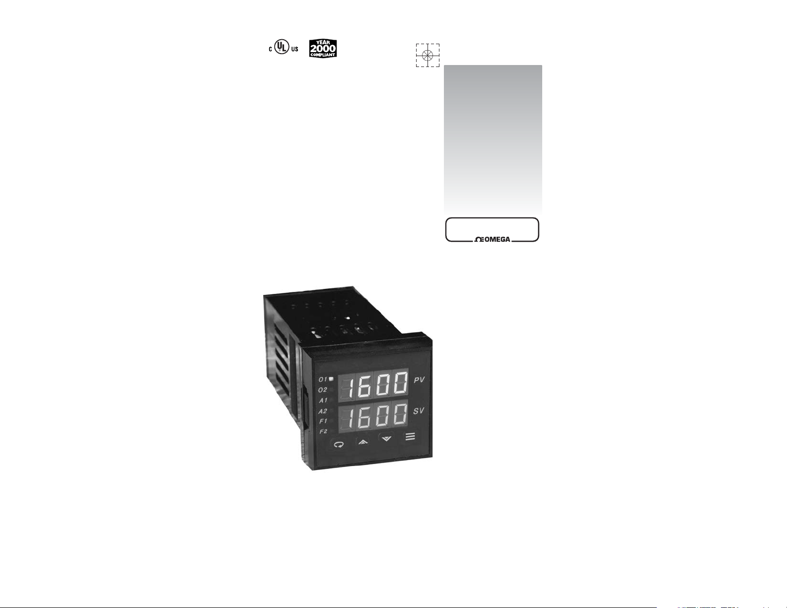
Features
Field-Selectable Thermocouple, RTD, Current or Voltage Input
On/Off Through Full PID Operation
Autotuning - Heat or Cool
Eight-Segment Ramp/Soak
On/Off Output with Adjustable Hysteresis and Deadband
Dual Output Capability
Field-Configurable Process or Deviation Alarms
Bumpless, Auto-Manual Transfer
NEMA 4X Front Panel, “Watertight”
Dual 4-Digit (0.36"), 7-Segment Alphanumeric Display
Selectable Ramp to Setpoint
Alarm Inhibit
Loop Break Alarm Capability
Available Options Include Serial Communications, Contact/
Digital Input, Remote Analog Setpoint, Transducer Excitation,
Auxiliary Output, Dual Alarms, or Electromechanical Relay
Alarm.
Approvals: UL, cUL, CE
OMEGAnet®On-Line Service Internet e-mail
www.omega.com [email protected]
omega.com
TM
®
It is the policy of OMEGA to comply with all worldwide safety and EMC/EMI regulations that apply. OMEGA is constantly pursuing certification of
its products to the European New Approach Directives. OMEGA will add the CE mark to every appropriate device upon certification.
The information contained in this document is believed to be correct, but OMEGA Engineering, Inc. accepts no liability for any errors it contains, and
reserves the right to alter specifications without notice.
WARNING: These products are not designed for use in, and should not be used for, patient-connected applications.
Benelux:
Postbus 8034, 1180 LA Amstelveen
The Netherlands
TEL: +31 (0)20 6418405 FAX: +31 (0)20 6434643
Toll Free in Benelux: 0800 0993344
e-mail: [email protected]
Czech Republic:
Rude´arma´dy 1868, 733 01 Karvina´ 8
TEL: +420 (0)69 6311899 FAX: +420 (0)69 6311114
Toll Free in Czech Republic: 0800-1-66342
e-mail: [email protected]
France:
9, rue Denis Papin, 78190 Trappes
TEL: +33 (0)130 621 400 FAX: +33 (0)130 699 120
Toll Free in France: 0800-4-06342 e-mail: [email protected]
Servicing Europe:
USA and Canada:
Sales Service: 1-800-826-6342 / 1-800-TC-OMEGA
®
Customer Service: 1-800-622-2378 / 1-800-622-BEST
®
Engineering Service: 1-800-872-9436 / 1-800-USA-WHEN® TELEX:
996404 EASYLINK: 62968934 CABLE: OMEGA
USA: ISO 9001 Certified
One Omega Drive, P.O. Box 4047
Stamford CT 06907-0047
TEL: (203) 359-1660
FAX: (203) 359-7700
e-mail: [email protected]
Servicing North America:
For immediate technical or application assistance:
Mexico:
TEL: (001) 800-826-6342
FAX: (001) 203-359-7807
En Espan~ol: (001) 203-359-7803
e-mail: [email protected]
[email protected]
Germany/Austria:
Daimlerstrasse 26, D-75392
Deckenpfronn, Germany
TEL: +49 (0)7056 3017 FAX: +49 (0)7056 8540
Toll Free in Germany: 0800 TC-OMEGA
SM
e-mail: [email protected]
United Kingdom: ISO 9002 Certified
One Omega Drive
River Bend Technology Centre
Northbank, Irlam
Manchester M44 5EX United Kingdom
TEL: +44 (0)161 777 6611 FAX: +44 (0)161 777
6622
Toll Free in United Kingdom: 0800488488
e-mail: [email protected]
Canada:
976 Bergar
Laval (Quebec) H7L 5A1
TEL: (514) 856-6928
FAX: (514) 856-6886
e-mail: [email protected]
Page 3
In addition to presenting a potential fire hazard, high
voltage and high temperature can damage equipment
and cause severe injury or death. When installing or using
this instrument, follow all instructions carefully and use
approved safety controls. Electrical connections and wiring
should be performed only by suitably trained personnel.
Do not locate this instrument where it is subject to excessive
shock, vibration, dirt, moisture, oil, or other liquids. The safe
operating temperature range for this unit is 32°F to 140°F
(0°C to 60°C).
This unit has been tested and found to be compliant with
“NEMA Type 4X Enclosure - For Indoor Use Only.” When
properly installed, this controller will maintain the integrity of
a NEMA enclosure and remain “Watertight.” This rating is
only applicable when the controller is properly installed into a
suitably rated NEMA Type 4X housing.
Safety Warning
Table of
Contents
Installation
1
Dimensions and Mounting 2
Wiring 3
Output Types 6
Operation
7
Front Panel Controls 7
Power On 8
Security Levels 8
Operating Modes 10
Menu System Overview 11
Initial Setup Sequence 15
Parameter/Menu Descriptions
17
Input Menu 18
Temperature Input 20
Process (Linear) Input 20
Display Menu 20
Output Menu 21
PID Output and Control Menus 22
On/Off Output and Control Menus 23
Alarm Outputs 25
Autotune Damping 26
Ramp and Soak Menu 26
Supervisor Menu 28
Calibration Menu 29
Options Menu 29
AutoTuning
30
Manual Tuning
32
Error Codes
33
Technical Specifications
34
Ordering Codes
37
Recalibration Procedures
38
Quick– Helps
39
Glossary
42
Quick Setup Instructions
44
For information and
operating instructions
related to installed
options and digital
communications, refer
to the Series CN8200
options and communications manual supplied
with your controller.
Page 4
1
Installation
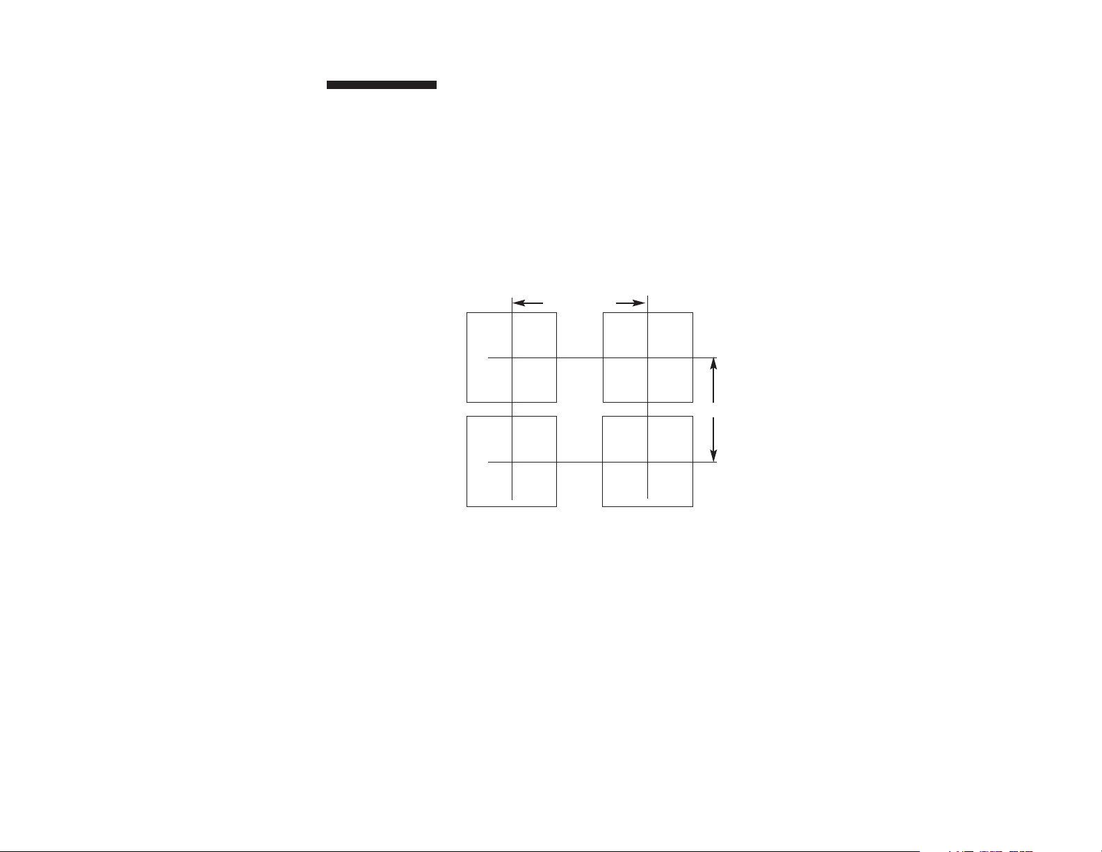
Measurements betw een
centerlines of panel
cutouts are the minimum
recomm ended.
Unpacking and Inspection
1. Inspect shipping carton for obvious signs of mishandling.
2. After removing the controller from the shipping carton,
inspect it carefully for damage. Never attempt to install
and use a damaged unit.
3. Verify that the ordering code number indicated on the side
of the controller matches what was ordered.
Figure 1.
Recommended Panel Layout for Multiple Controllers
C
L
C
L
C
L
C
L
2.850" (72.4 mm)
2.150" (54.6 mm)
Page 5
3
Wiring
IMPORTANT: All electrical wiring connections should be made
only by trained personnel, and in strict accordance with the
National Electrical Code and local regulations.
The Series CN8200 controller has built-in circuitry to reduce
the effects of electrical noise (RFI) from various sources.
However, power and signal wires should always be kept
separate. We recommend separating connecting wires into
bundles: power; signal; alarms; and outputs. These bundles
should then be routed through individual conduits. Shielded
sensor cables should always be terminated at one end only.
If additional RFI attenuation is required, noise suppression
devices such as an R.C. snubber at the external noise source
may be used.
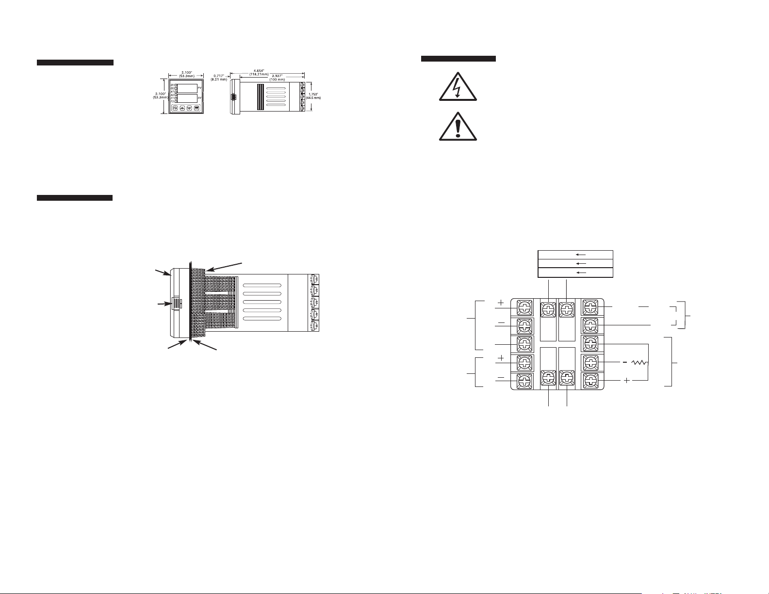
Figure 4. Contact Identification
2
Mounting
Dimensions
Figure 2. Case Dimensions
Prior to mounting the Series CN8200 in your panel, make
sure that the cutout opening is of the right size, 1.771" x
1.771" (45 mm x 45 mm), and deburred to enable a smooth
fit. A minimum of 4" (100 mm) of depth behind the panel is
required.
Figure 3. Series CN8200 Mechanical Components
Insert the Series CN8200 through the front panel cutout and
slide the mounting collar back onto the unit from behind the
panel. Push the mounting collar up tight to the back of the
mounting panel.
Bezel
Case Clip
Grips
Gasket
Customer Panel
When properly installed
through a NEMA
enclosure, the integrity
of the enclosure will be
maintained and will
remain “Watertight.”
ALARM & COMM.
N.O.
RCV
B (-)
COM
XMT
A (+)
A1
RS 232
RS 485
OUTPUT 1
C
N.C.
N.O.
N.O.
OUTPUT 2
C
1
2
13
3
11
4
5
L1 L2
100 - 250 V 50/60 Hz
100 - 250 Vdc (Auto Polarity)
24 Vac/Vdc (Auto Polarity)
6
7
14
8
12
9
10
232/485
GND
T/C
COM
N.O.
RTD
A2
SENSOR
INPUT
ALARM
&
COMM.
Page 6
5
Wiring
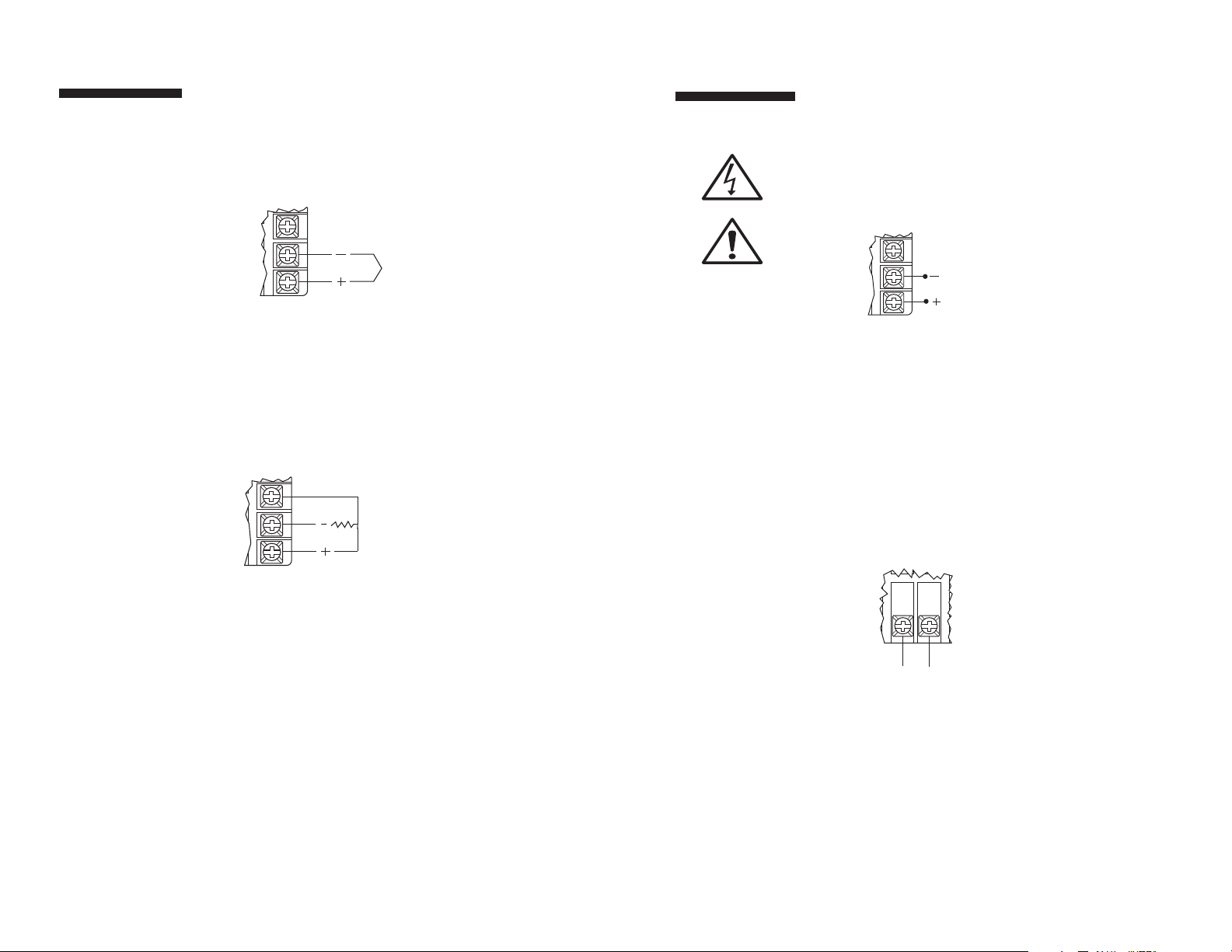
Figure 7. Process and Linear Input Wiring
Voltage Inputs: Connect the positive voltage input to contact
#10; the negative input to contact #9. Current Inputs: Connect
the positive current input to contact #10; the negative input to
contact #9.
The Series CN8200 power supply accepts 100 to 250 Vac and
100 to 250 Vdc line power without any switch settings or
polarity considerations. All connections should be made in
accordance with the National Electrical Code and local
regulations, using only NEC Class 1 wiring for all power
terminals.
It is advisable, but not necessary, to fuse one leg of the
incoming power line, contact #11, with a 2AG, 0.5 amp rated
fuse.
It is recommended that instrument power and load
power be fused independently.
Figure 8. Power Wiring Connection
100 - 250 V 50/60 Hz
100 - 250 Vdc (Auto Polarity)
8
9
10
(CURRENT
and VOLTAGE)
4
Wiring
Figure 5. Thermocouple Input Wiring
Make sure that you are using the appropriate thermocouple
and extension wire. Connect the negative lead (generally
colored red in ISA-type thermocouples) to contact #9;
connect the positive lead to contact #10. Extension wires
must be the same polarity as the thermocouple.
Figure 6. RTD Wiring
The Series CN8200 accepts input from 2- or 3-wire, 100 ohm
platinum resistance temperature detectors (RTDs). Connect
2-wire RTDs to contacts #9 and #10, with a jumper across
contacts #8 and #10. Keep leads short and use heavy gauge
copper extension wire, if necessary, to minimize lead
resistance. For long runs, 3-wire RTDs should be used.
Thermocouple circuit
resistance should not
exceed 100 ohms for
rated accuracy; errors
will occur at higher
resistance values.
If shielded thermocouple wire is used,
terminate the shield
only at one end.
Note: For 2-Wire RTD
Jumper 8 & 10
8
9
10
T/C
8
9
10
RTD
3
4
5
8
11
12
9
10
L1 L2
Page 7
7
Output Type Description
R 5 A (120/240 Vac) relay, normally open,
used for switching resistive loads. If an “R”
output is selected, order CNQUENCHARC. If
relays or solenoids are to be driven, select
the “T” output.
DC 20 Vdc pulsed output for solid-state relays.
T 1 A @ 120/240 Vac, solid-state relay, zero
voltage-switched and optically isolated from
drive signal. Only resistive loads to 1A may
be controlled directly. Larger loads may be
controlled using an external contactor.
F 4-20 mA, full output to load with 500 ohm
impedance max. (suppressed).
FH High impedance 4-20 mA (1000 ohm max).
6
Output Types
The Type “R” output
is a mechanical device
and subject to wear.
To extend the life of
the relay, set the Cycle
Time for the relay
output to the longest
duration that still
affords good control.
When you ordered your Series CN8200 controller specific
output types were specified, designated as “R”, “DC”, “T”,
“F”, or “FH”. You also had the option of configuring your
controller with either one or two output actions. The numbers
below are suggested for most typical applications.
For Control Output Type — Select Cycle Time
(in seconds)
R >15
DC 0.2
T 15*
F 0.2
FH 0.2
*“T” outputs directly driving non-inductive loads (small heaters) can have
cycle times as low as 0.2 seconds.
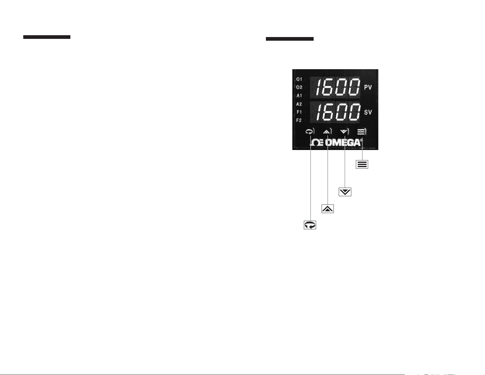
Mode/Enter Key
Used to enter Parameter
selections, access operating
modes, release latched alarms,
and index through menu items.
Lower Key
Used to decrease values.
(Hold for fast-step progression)
Raise Key
Used to increase values.
(Hold for fast-step progression)
Menu Access Key
Used to enter or exit the menu system, index to the next
menu, and enter the Security Level menu.
Operation
Figure 9. Front Panel Controls and Indicators
Page 8
9
Power On
When power is first applied to the Series CN8200, all
segments of the LED displays will be momentarily illuminated
while the instrument goes through a series of diagnostic
checks to verify proper operation. A software version number
will then
appear in the lower display, followed by a configuration code (upper display) and the communications protocol
which is supported (lower display).
IMPORTANT:
On initial startup, there is a possibility that
outputs may be activated. We recommend placing the unit
in Standby mode until you have configured the controller
according to your application requirements. To place the
controller in Standby, follow this procedure:
1) Press and hold Mode/Enter key until
a menu label appears in upper display
(approximately three seconds).
2) Press Raise or Lower key until
appears in the lower display.
3) Press Mode/Enter key. (The upper display will
alternate between and process value.)
Operations Overview
The user interface of the Series CN8200 allows you to use
menus to set up the instrument, set the desired security level,
change the setpoint, and conveniently change operating
modes. Figure 10 on page 20 provides a functional representation of the user interface and the key presses necessary to
perform the basic functions.
The Series CN8200
controller's functional
hierarchy is organized
into three distinct userprogramm able
groupings: Security
Level, Menu S ystem,
and Operating Mode.
Please provide the
software version
number, communications protocol, and
the controller’s full
model number, when
contacting us regarding
your controller.
8
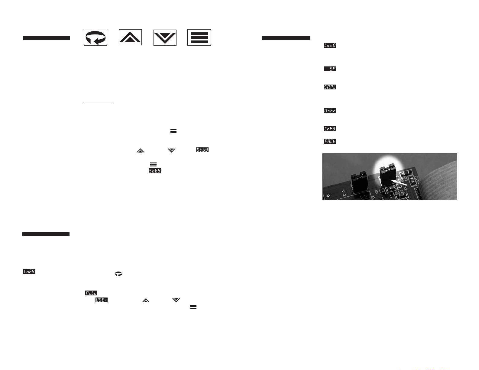
Security Levels
The security level feature allows you to limit access to the
menus, setpoint, and operating mode selection according to
the needs of your application. The security levels provided
are Key Lockout, Setpoint, Setpoint plus Mode, User,
Configuration, and Factory. To view or change security
level from the Process Variable display, press and hold the
Menu Access key for approximately 10 seconds.
(Ignore the menu label that will appear in the upper display
after approximately three seconds.) The controller will display
(Access Level) and the current security level label,
e.g., . Use the Raise or Lower keys to index
through the security levels. Press the Mode/Enter key
once to select the new security level desired and return to the
Process Value display.
The controller’s initial
security level, set at the
factory, is Configuration
. When you have
completed configuring
the instrument, we
recomm end the security
level be set to the most
restrictive level suitable
for your application.
Security Levels
Security Levels and Access Restrictions
Key Lockout Highest security level. No access to any
controller functions. To escape, follow
instructions above for changing security
levels.
Setpoint No access to menus. Only allows setpoint
value or output percentage (manual mode)
to be changed.
Setpoint
plus Mode No access to menus. Only allows setpoint
value, output percentage (manual mode),
or operating mode to be changed.
User All “Setpoint” level privileges as well as
access to Operating Mode, Autotune, and
Control menus.
Configuration All “User” level privileges as well as Input,
Output, Display, and Supervisor menus
Factory All “Configuration” level privileges as well
as access to Calibration menu.
NOTE:
Removing this jumper on the microcontroller board disables
the keypad, thus preventing any operator access.
JMPØ3
Page 9
11
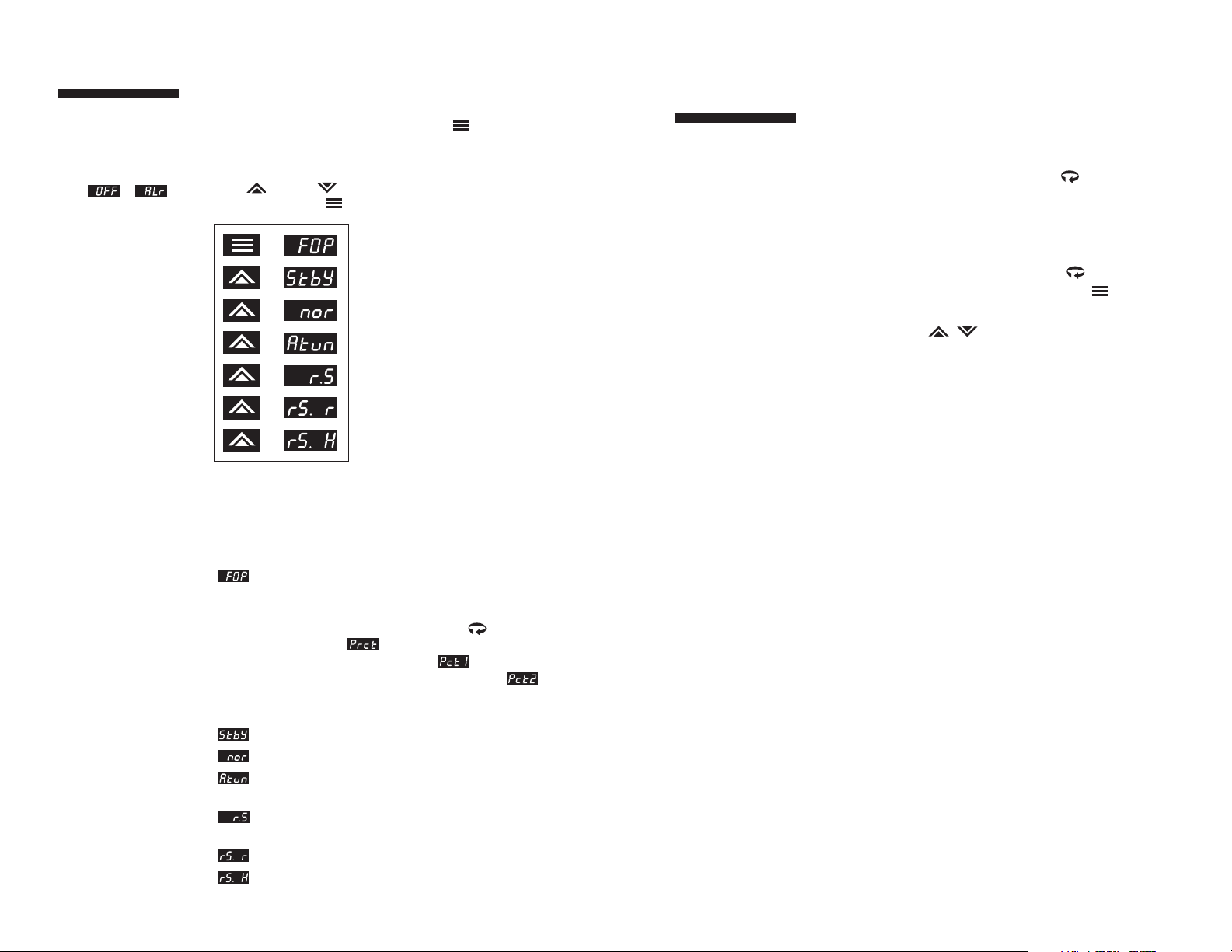
Manual Used to set control output percentage
(Fixed Output Percentage) independent
of Process Value. To set percentage,
use the Menu Access key to select
and the Raise or Lower keys
to set the value. is displayed if
Output 1 is a control output.
is
displayed if Output 2 is a control
output
.
Standby Used to disable control outputs.
Normal Normal automatic control.
Autotune Used to initiate the autotuning
sequence (from Standby only).
Ramp/Soak Used to start ramp/soak recipe mode.
Recipe
Run Used to enable Run function
Hold Used to enable Hold function
Manual operating mode
overrides automatic
control, allowing you to
control the outputs
using a fixed ercentage
of output power,
regardless of the process
variable or setpoint.
If current automatic
control is PID, transfer
to Manual mode is
“bumpless.”
Operating Modes
The Series CN8200’s operating modes are: Manual, Standby,
Normal, Autotune, Ramp/Soak Recipe, Run and Hold. To select a
different operating mode, press the Mode/Enter key for three
seconds.
The operating mode that the controller is currently in will be
displayed. To index through the available operating modes, press the
Raise or Lower keys. When the desired mode is displayed,
press the Mode/Enter key once to select the mode.
Remember to press the
Mode/Enter key after
making your selection.
If both outputs are
set to or ,
the Series CN8200 will
function as a noncontrolling indicator.
Control outputs will be
disabled and the
Operating Modes will
not be displayed.
Manual
Standby
Normal
Autotune
(Only available when unit is placed in Standby mode
and one output is PID.)
Start Ramp/Soak R ecipe
(Only when programmed.)
Run
(Only available when recipe is active.)
Hold
(Only available when recipe is active.)
A description of the available operating modes
is provided on the next page.
Menu System
Overview
The Parameter Menu System is organized into ten basic
menus: Input, Display, Output, Control, Alarm, Tune,
Recipe, Supervisor, Calibration, and Option. To access the
Menus, press and hold the Menu Access key for approximately 3 seconds until a menu label appears in the upper
display. There are additional menus presented when an option
is selected under the Option menu; however, the options
are non-functional unless the appropriate option board has
been installed. Pressing the Menu Access key indexes
from menu to menu. Pressing the Mode/Enter key
indexes through the parameters in a particular menu. The
Raise and Lower keys are used to modify the
visible menu parameter.
Each menu contains a logical group of parameters related
to one another. Furthermore, the sequence of the menus
has been carefully chosen to put the most important setup
menus first.
If a key press is not
sensed within five
minutes, the controller
automatically exits the
Menu System and
reverts to the Process
Value display.
10
Page 10
13
Menu System
Overview
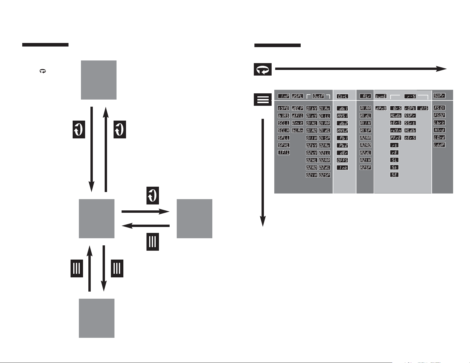
Figure 10. Series CN8200 Functional Diagram
for 3 seconds
Menu
System
To return to Process
Value at any time,
press and hold Menu
Access key f or
three seconds
for 3 seconds
12
Security
Levels
Process
Variable
Display
Mode
Selection
for 10 seconds
for 3 seconds
once
once
Menu System
Overview
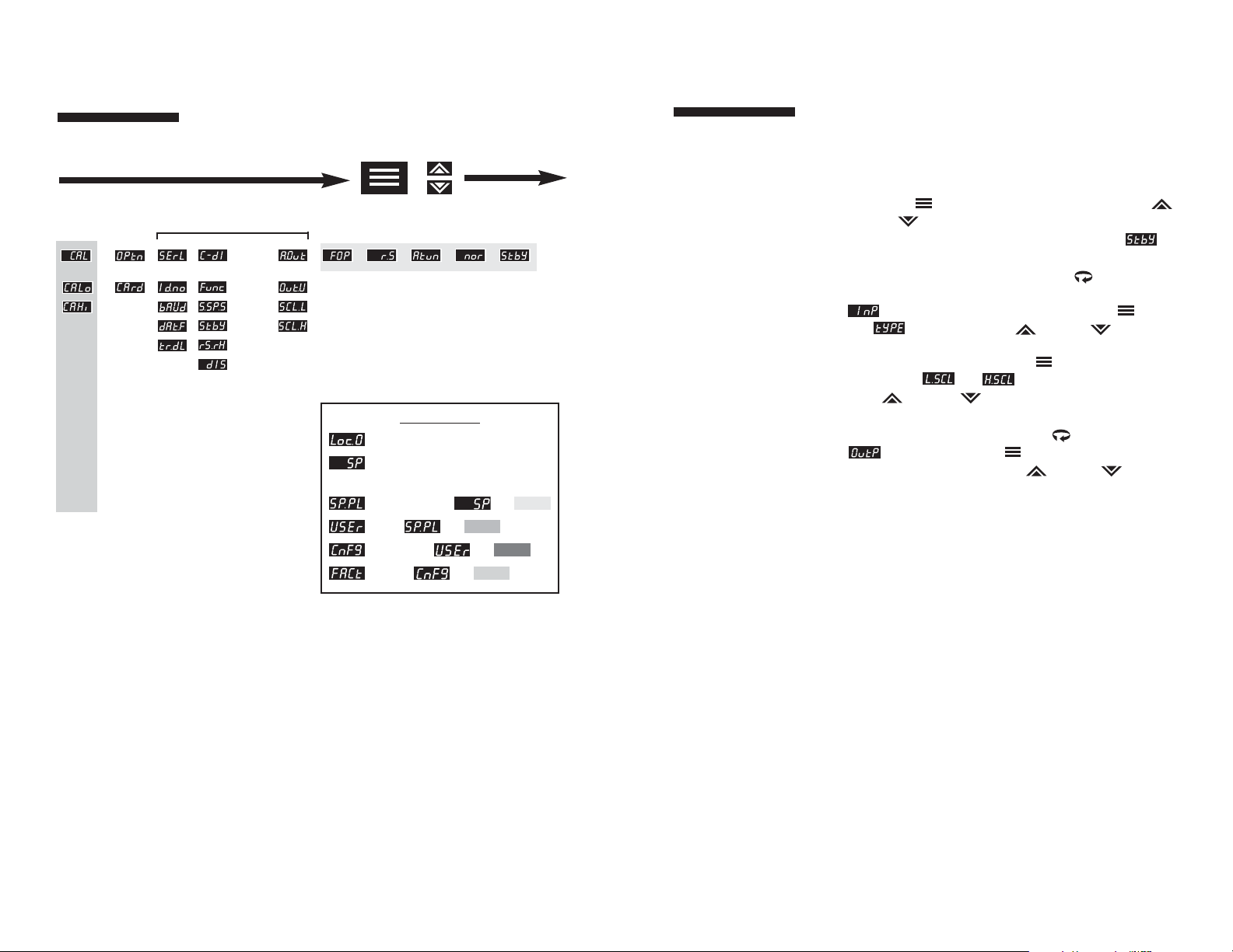
Figure 11. Chart of Series CN8200 Menu System and
Security Levels
(CONTINUED TO NEXT PAGE)
Mode/
Enter Key
Menu
Access Key
(number)
(number)
(number)
(number)
(number)
NOTE:
Parameter labels displayed will vary, depending
upon the controller’s configuration.
Page 11
15
Initial Setup
Sequence
If a key press is not
sensed within five
minutes, the Menu
System is automatically
exited and the
controller reverts to the
Operating Mode/
Process Value display.
These setup instructions
apply to PID-type
control outputs.
Many of the menu parameters you will need to set up the
controller for your application are interdependent. We
recommend following the steps below when configuring
your Series CN8200.
1) Place the unit in Standby Mode as follows. Press the
Mode/Enter key for three seconds. Press the Raise
or Lower key to select Standby. Press the Mode key
again and the upper display will alternate between
and the process value.
2) Input Type. Press and hold Menu Access key for three
seconds to access the menu system. The Input menu
will be displayed. Then press Mode/Enter key
until appears. Use Raise or Lower key to
select Input Type. If Input Type is set to one of the linear
input options, use the Mode/Enter key to scroll to
scaling limits, and
,
before proceeding. Use the
Raise or Lower key to set low and high scaling
limits.
3) Output Type. Press the Menu Access key to display
. Use the Mode/Enter key to index to the Output
Type parameter. Using the Raise or Lower keys,
select the correct Output Type for your application. Follow
these steps (using the Mode/Enter and Raise or Lower
keys) to set the Output Action, Cycle Time, and Limit
parameters for PID outputs. Alarm or on/off output
settings and displays will be different. Refer to Output
menu description on page 31.
14
Mode/
Enter Key
(three seconds)
Functional When Option Card Installed*
Raise/
Lower Key
Security Levels
(Key Lockout) = No Access
(Setpoint) = Setpoint Value or Output
Percentage (Manual Mode)
(Setpoint plus Mode) = Plus
(User) = Plus
(Configuration) = Plus
(Factory) = Plus
*See options manual for
parameter selections.
Figure 11. Chart of Series CN8200 Menu System and
Security Levels
(CONTINUED TO FROM PREVIOUS PAGE)
Menu System
Overview
Page 12
17
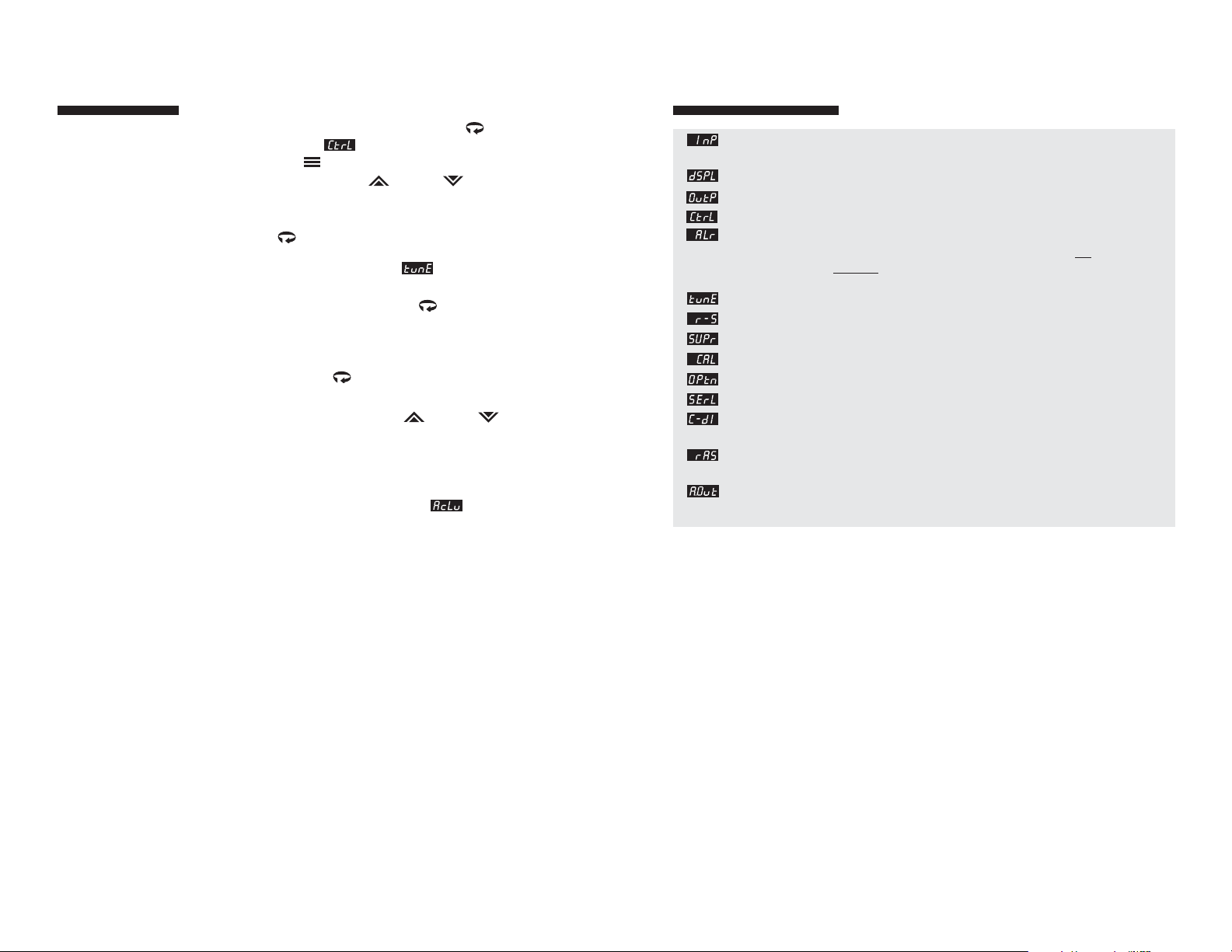
Input Used to select sensor-related parameters, such as input type,
limits, and scaling.
Display Used to set or change decimal position and display units.
Output Used to specify output usage, control methods, and alarms.
Control Used to select parameters associated with the control methods.
Alarm Used to select alarm parameters .
Note: This menu is also functional for controllers
not
equipped
with alarm hardware; however, alarm indication
will be only visual via the A1 and A2 LEDs on the front panel.
Tune Used to set the autotune damping parameter.
Recipe Used to set ramp and soak parameters.
Supervisor Used to set fail-safe and supervisory parameters.
Calibration Used to recalibrate input.
Option Used to select installed option.
Communications (Option) Used to set serial communications parameters.
Contact/Digital
Input
(Option) Used to select switch input functions.
Remote Analog
Setpoint
(Option) Used to enter remote analog setpoint parameters.
Auxiliary Output (Option) Used to set auxiliary output parameters.
Menus and Parameter
Descriptions
Menus and Parameters
16
Initial Setup
Sequence
4) If manual tuning the controller, set Control Menu
parameters by pressing the Menu Access key
repeatedly until is displayed. Then, use the
Mode/Enter key to index through the available
selections and the Raise or Lower keys to select
the appropriate setting. Otherwise, proceed to Step 6.
5) If autotuning the controller, press and hold the Menu
Access key for three seconds to access the menu
system. Press the Menu Access key repeatedly until the
Autotune Damping parameter is displayed. Make
sure the Damping parameter is set properly (see page 37).
Press and hold the Menu Access key for three
seconds to return to the Process Variable display and
proceed to Step 4 on page 43.
6) Return to Process Variable Display. Press and hold
the Menu Access key for three seconds to return
to PV display.
7) Adjust setpoint. Use the Raise or Lower key to
enter the desired setpoint. Wait for process to stabilize
before proceeding, e.g., in the case of a heating process,
return to ambient temperature.
8) Security Level. Press and hold the Menu Access key
for approximately 10 seconds until is displayed.
Using the Raise or Lower keys, set the most restrictive
level suited to your application. See page 16.
IMPORTA NT: Upon
entering a new value,
you MUST either press
the Mode/Enter key, the
Menu A ccess key, or
index to a different
parameter in order for
the new value to register.
The controller will N OT
accept new values
without a key press.
Page 13
19
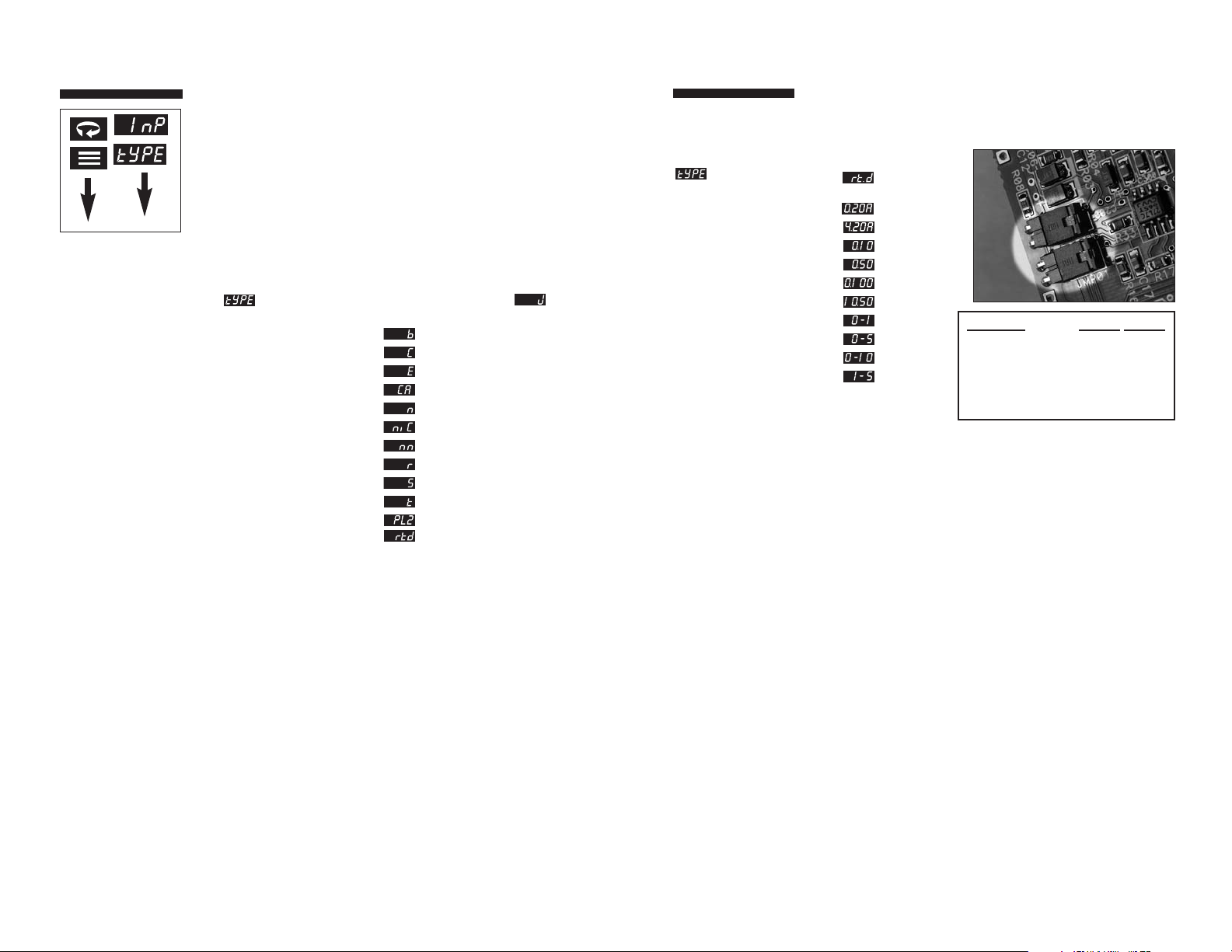
Input Type JMPØ1 JMPØ2
Thermocouple Out Out
RTD Out Out
Voltage <100 mV Out Out
Voltage >100 mV In Out
Current Process In In
Input Menu
JMPØ2
Input Menu (continued)
Display Parameter Selection
Input Type 100 ohm
compressed RTD
0-20 mA
4-20 mA
0-10 mV
0-50 mV
0-100 mV
10-50 mV
0-1 V
0-5 V
0-10 V
1-5 V
Input Jumper Settings
18
NOTE: FOR A MORE DETAILED DESCRIPTION OF MENU
PARAMETERS, REFER TO THE GLOSSARY
WHICH BEGINS ON PAGE 42.
The first parameter that needs to be set is Input Type. The remaining
Input Menu parameters will change, depending upon whether a linear
input type or a temperature input type is selected. Other menu
parameters related to the sensor range may also change. After
selecting your Input Type, refer to the corresponding section on page
20 for the remainder of the Input Menu parameters.
Input Menu
Display Parameter Selection
Input Type
Type J thermocouple
Type B thermocouple
Type C thermocouple
Type E thermocouple
Type K thermocouple
Type N thermocouple
Type NIC thermocouple
Type NNM thermocouple
Type R thermocouple
Type S thermocouple
Type T thermocouple
Platinel II thermocouple
100 ohm
platinum RTD
Input Menu
Page 14
21
Output Menu
The first parameter that needs to be set in the Output Menu is the
Output Type.There are three possible Output Type configurations:
PID, On/Off, Alarm, or Off. (If you are not sure which Output Type is
best for your particular application, refer to the Glossary for an
explanation of Output Types.) The remaining menu parameters in the
Output Menu will change, depending on the Output Type selected.
The Control Menu will also change, depending on the Output Type
selected. If you ordered two outputs, you can select two different
Output Types. After setting your Output Type, refer to the corresponding sections below for the remaining Output Menu parameters.
For simplification purposes, the following sections assume the same
Output Type for both outputs. If you selected different Output Types,
refer to both of those sections.
Output Type
Display Parameter Selection
Output 1 Type
Output 2 Type
20
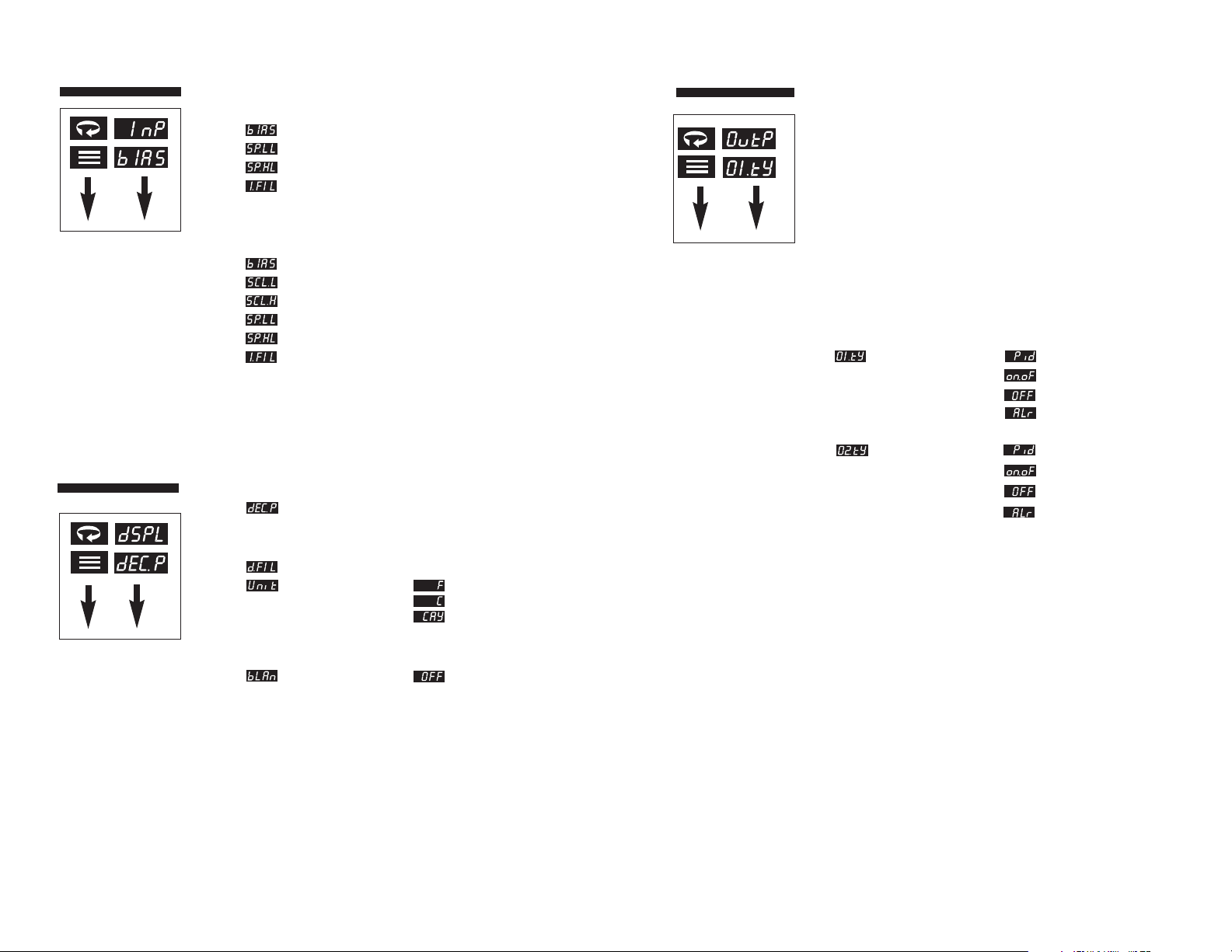
Temperature Input Type
Display Parameter Selection
Bias -100 to 100
Lower Setpoint Limit Span of Sensor
Upper Setpoint Limit Span of Sensor
Filtering 0.1-10.0 sec.
Linear Input Type
Display Parameter Selection
Bias -100 to 100
Low Scale -1999 to 9999
High Scale -1999 to 9999
Lower Setpoint Limit Span of Sensor
Upper Setpoint Limit Span of Sensor
Filtering 0.1-10.0 sec.
Input Menu
Display Menu
Display Parameter Selection
Decimal Position 0-3 Linear Inputs
0-1 TC/RTD
Filter 0.1-10.0 sec
Units* Fahrenheit
Celsius
Kelvin
*NOTE:
Does not appear for linear inputs.
Blanking
,
0-9999 sec
Page 15
Output Menu
Control Menu
Display Parameter Selection
Output 1 Action (Reverse-acting)
(Direct-acting)
Output 2 Action (Reverse-acting)
(Direct-acting)
Display Parameter Selection
Deadband 1 Negative span of sensor to
positive span of sensor
Hysteresis Output 1 1...to span of sensor
Deadband 2 Negative span of sensor to
positive span of sensor
Hysteresis Output 2 1...to span of sensor
If both outputs are set to in the Output Type Menu, the
controller will function as a non-controlling indicator. Control
outputs will be disabled and the Operating Modes will not be
displayed.
On/Off Output Type
On/Off Output Type
23
Control Menu
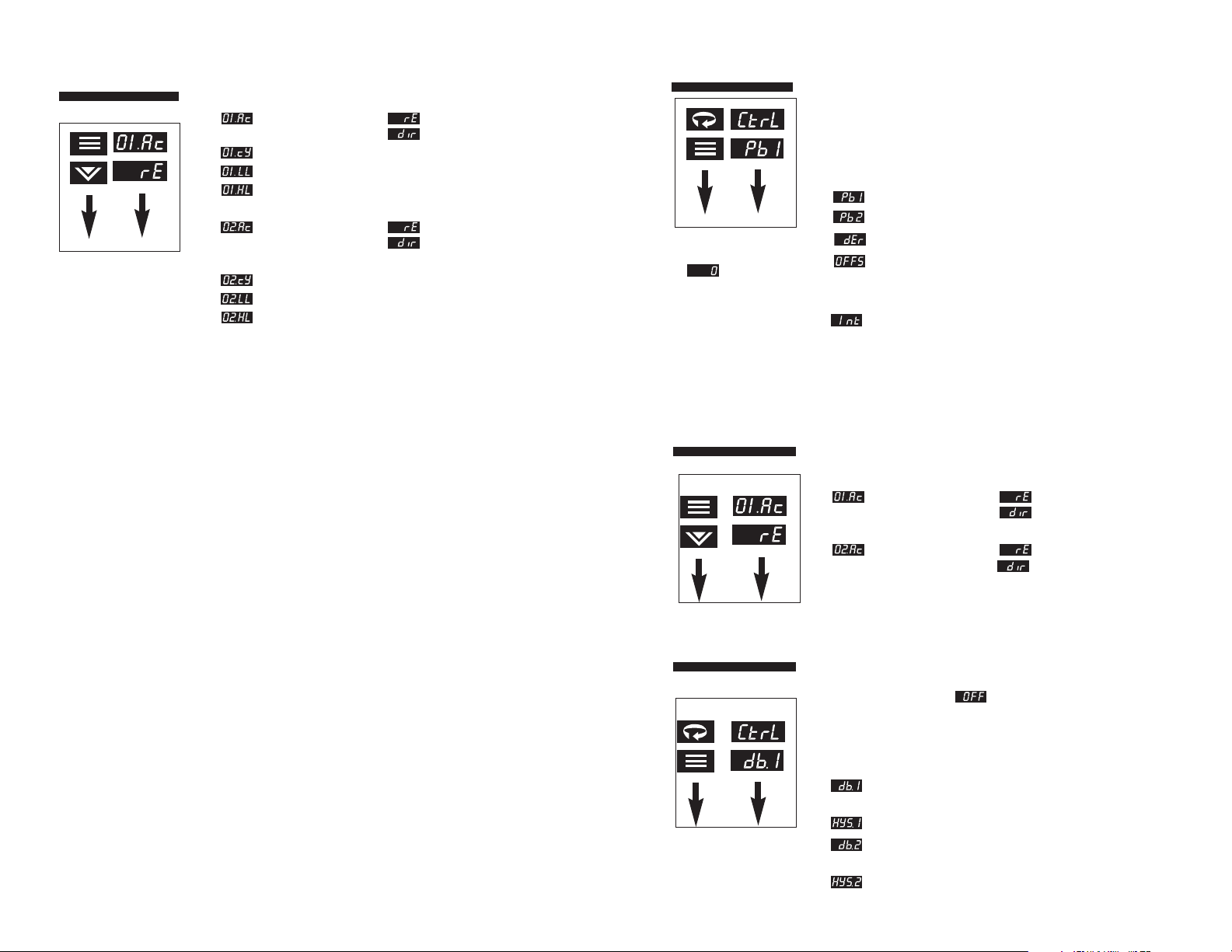
As with the Output Menu, the Control Menu will change, depending
upon the Output Type selected.
Note: These parameters are automatically set during the autotune procedure. We do not recommend
altering the value of these control parameters unless your process
requires manual tuning.
Setting Derivative (R ate)
or Integral (Reset)
to disables that
aspect of PID control.
If BOTH outputs are set
to direct-acting or
BOTH outputs are set
to reverse-acting, then
only one proportional
band selection will
be displayed.
Display Parameter Selection
Proportional Band 1 1...to span of sensor
Proportional Band 2 1...to span of sensor
Derivative Action (Rate) 0 to 2400 seconds
Manual Reset OFF, -100% to 100%
NOTE: The Integral Action (Auto Reset) parameter appears only if OFF
is selected in the Manual Reset parameter.
Integral Action (Auto Reset) 0 to 9600 seconds
PID Output Type
22
Output Menu
Output 1 Action (Reverse-acting)
(Direct-acting)
Output 1 Cycle Time* 0.2; 1 to 120 seconds
Output 1 Low Limit 1-100%
Output 1 High Limit 1-100%
Output 2 Action (Reverse-acting)
(Direct-acting)
Output 2 Cycle Time* 0.2; 1 to 120 seconds
Output 2 Low Limit 1-100%
Output 2 High Limit 1-100%
*Recommended Cycle Time Settings
Output Type Recommended Setting (seconds)
R (relay, 5A/3A) 15 to 120
DC (pulsed 20 Vdc) 0.2
F (4-20 mA) MUST be set to 0.2
FH (4-20 mA) MUST be set 0.2
T (S.S. relay) 15 to 120**
**“T” outputs directly driving non-inductive loads (small heaters) can have
cycle times as low as 0.2 seconds.
PID Output Type
Page 16
25
Output Menu
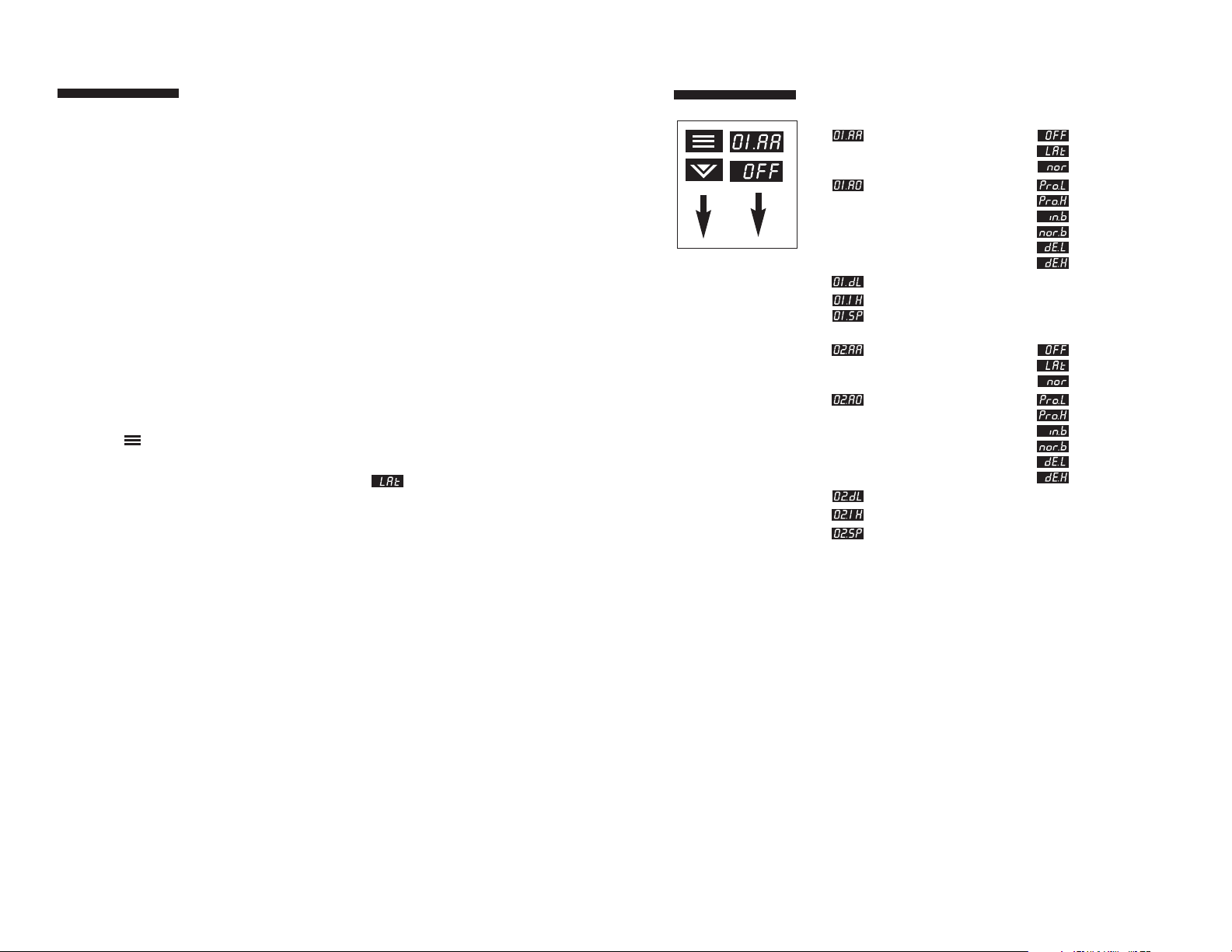
Display Parameter Selection
Output 1 Alarm Action
(Latching)
(Normal)
Output 1 Alarm Operation (Process Low)
(Process High)
(Inverse Band)
(Normal Band)
(Deviation Low)
(Deviation High)
Output 1 Alarm Delay 0-9999 sec
Output 1 Alarm Inhibit 0-9999 sec
Output 1 Alarm Setpoint Span of Sensor
Output 2 Alarm Action
(Latching)
(Normal)
Output 2 Alarm Operation (Process Low)
(Process High)
(Inverse Band)
(Normal Band)
(Deviation Low)
(Deviation High)
Output 2 Alarm Delay 0-9999 sec
Output 2 Alarm Inhibit 0-9999 sec
Output 2 Alarm Setpoint Span of Sensor
Note: The Control
Menu does not apply to
an Alarm Output Type;
therefore, the Control
Menu does not appear.
Alarm Output Type
24
Notes On Alarms
Four types of alarms are available: Process, Deviation,
Inverse Band, and Normal Band. All alarms may be
configured to be inhibited on power-up for a configurable
time duration.
Process Alarm: Activates at preset value, independent
of setpoint. “High” process alarm
activates at and above alarm setting.
“Low” process alarm activates at and
below alarm setting.
Deviation Alarm: Activates at a preset deviation value
from setpoint. “High” or “Low” deviation
alarm activates above or below setpoint
according to the preset deviation value.
Inverse Band Alarm: Activates when the process is within
a specified band centered around the
setpoint.
Normal Band Alarm: Activates when the process exceeds
a specified band centered around the
setpoint.
Latching Alarms
The Series CN8200’s alarms may also be configured as
latching alarms by selecting in the Alarm Action
parameter selection.
Deviation, Inverse
Band, and Normal
Band Alarms track
with setpoint.
When a latching alarm
has been activated and
the alarm condition has
been remov ed, the
Mode/Enter key
must be pressed to
unlatch the alarm.
Page 17
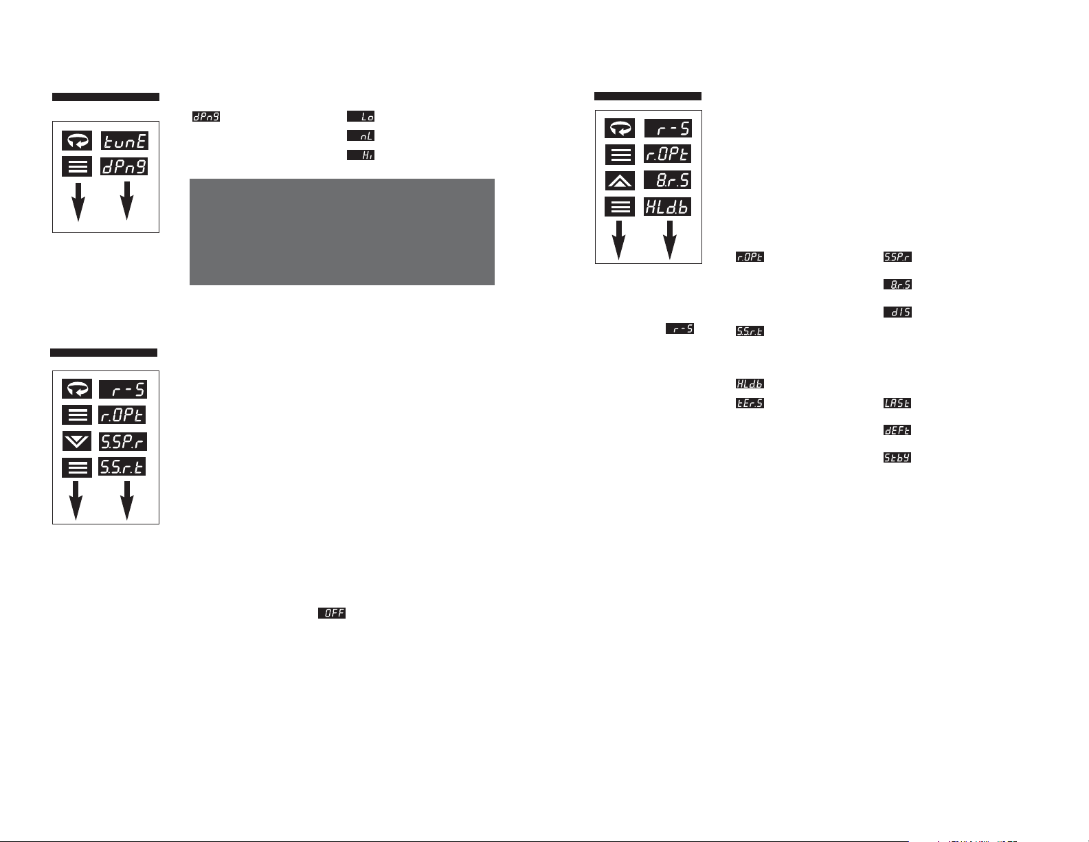
27
Recipe (Ramp/
Soak) Menu
Power Fail Resume
Setting this parameter to On will cause the control to resume
a recipe which was active when a power failure occurred. The
recipe will resume at the start of the last active ramp or soak
segment.
Ramp/Soak Events (1-8)
(If alarms are configured as ramp/soak events.)
Ramp/Soak events occur at the beginning of their designated
segment. All events are terminated once the recipe has been
completed or terminated.
Display Parameter Selection
Recipe Option Single-Setpoint
Ramp
Multi-Step Ramp
Disabled
Single-Setpoint 1-9999 mins.
Ramp Time*
*NOTE:
Only available when single-setpoint ramp is selected.
Holdback Band Off-100
Termination State Last Setpoint
Default Setpoint
Recipe to Standby
If a ramp/soak error
condition occurs, the
upper display will
toggle between
and the numeric error
code for three seconds
before the recipe
terminates. Possible
error codes are:
02 = Recipe Empty
(i.e. no non-zero ramp
times)
05 = Insufficient
Setpoint-Process Value
Deviation
Recipe (Ramp/
Soak) Menu
Single Setpoint Ramp Time
This selection will cause the controller to ‘ramp’ the
process from the starting point (current process value)
to the setpoint in the time specified. This ramp will take
place at startup when selected from the Ramp/Soak menu.
The setpoint must be at least ±0.2% of sensor span for the
ramp to be employed.
Multi-Step Ramp
This selection will enable the programming of a recipe (make all
ramp/soak recipe variables visible). Recipes can be resumed on
startup if interrupted by a power failure or initiated, held, and
terminated from the front panel via the Mode Menu or with the
logic input option (initiate and held/resumed only).
Holdback Band
Specifies the maximum number of degrees above or below
setpoint that the process can be for the segment timer to keep
going. The timer will hold while the process settles back into the
band and then continue. If this feature is not desired, this
parameter should be set to which will disable it.
Termination State
This parameter determines what the control will do at the
completion of a recipe. Last Setpoint refers to the last
temperature specified in the ramp/soak recipe. Default
Setpoint refers to the standard setpoint which was in effect prior
to recipe initiation.
Recycle Number
Specifies the number of times after the first time that the recipe
is run before the program terminates.
26
Display Parameter Selection
Damping Low
Normal
High
Autotune
Damping Menu
Note: The damping parameter specifies how aggressively the
controller performs its autotuning. The “Normal” setting is a
compromise between the fast recovery and overshoot. The
“Low” setting provides faster recovery, but with the possibility
of overshoot; the “High” setting a slower recovery, but with
minimum or no overshoot.
Page 18
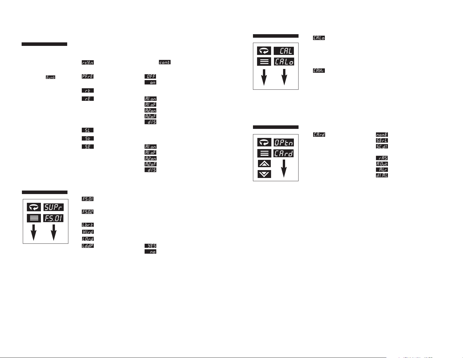
29
Toggles with the temperature value that should be input to
perform the low calibration operation.
The low calibration operation is triggered by pressing the
up arrow key.
Toggles with the temperature value that should be input to
perform the high calibration operation.
The high calibration operation is triggered by pressing the
up arrow key.
Calibration Menu
Options Menu
Display Parameter Selection
Installed Card
Serial Communications
Serial Communications
with Switch Input
Remote Analog Setpoint
Auxiliary Output
Alarm
Switch Input with Alarm
Supervisor Menu
Display Parameter Selection
Output 1 0 to 100%
Failsafe State of output
Output 2 0 to 100%
Failsafe State of output
Loop Break Time Off, 4-9600 sec
Highest Reading n/a
Lowest Reading n/a
Load Default
Parameters
Choosing “Yes” to Load Default Param eters resets all menu
parameters to factory settings.
The Failsafe State is
only enforced when a
problem is detected
with the process input.
It is not reliably
enforceable in
instances of internal
circuitry failure such as
EEPROM problems.
Output % High Limits
are ignored when the
unit enters a Failsafe
State.
28
NOTE:
The following seven parameters are only available when
multi-step ramp is selected.
Display Parameter Selection
Recycle Number 0-99,
(Recipe Executions)
Power Fail Resume Off
On
Ramp Times 1-8 0-9999 mins.
Ramp Events 1-8 Alarm 1 On
Alarm 1 Off
Alarm 2 On
Alarm 2 Off
Disabled
Soak Levels 1-8 Display Units, FS
Soak Times 1-8 0-9999 mins.
Soak Events 1-8 Alarm 1 On
Alarm 1 Off
Alarm 2 On
Alarm 2 Off
Disabled
Recipe (Ramp/
Soak) Menu
For Ramp Events and
Soak Events to be
employed, Alarm 1 or
Alarm 2 m ust be set for
event usage in
the Alarm Menu.
Page 19

31
Flashes
Autotuning
If a tune error condition occurs, the upper display will toggle
between and a numeric error code for three seconds
before the tune process terminates. The controller will then
automatically go into Standby mode when a tuning error
occurs. Possible error codes are:
02 = No PID Device Configured
03 = Incorrect Output Action
05 = Insufficient Setpoint-Process Value Deviation
08 = Invalid Tune Results
09 = Tune Timeout
Autotuning Procedure Diagram
Note: Keep in mind that the setpoint value must be at least
1% of span above or below the initial setpoint, and that the
process value must be stable prior to initiating the tune.
Hold for
three
seconds
Press
Press
Once
Current
Mode
Standby
Mode
Flashes
Hold for
three
seconds
Press until
appears
Press
Once
Controller is
now autotuning
Standby
Mode
Autotune
Mode
30
Autotuning
To place the controller in Autotune mode:
1) Configure the controller by following the directions for
Initial Setup Sequence through Step 3 on page 16. Set
damping parameter. (See page 26.)
2) If the controller is not already in Standby mode, place it
in Standby now as follows. Press and hold the
Mode/Enter key for three seconds. Display will
indicate your current operating mode. Press the Raise
key or Lower key to select Standby. Press Mode key
again and the display will alternate between and
the process value. This will deactivate all outputs.
3) If Setpoint Value has not been entered, adjust setpoint
now by using the Raise or Lower key to set the desired
setpoint.
4) Wait for process to stabilize before proceeding, e.g., in
the case of a heating and cooling process, return to
ambient temperature.
5) Initiate Autotuning. Press and hold the Mode/Enter key
again for three seconds, then press the Raise or Lower
key repeatedly until appears. Finally, press the
Mode/Enter key again. The display will alternately indicate
and process value as the controller “learns” the
proper proportional band, derivative, and integral values
for the process. If unacceptable overshoot occurs on
restart, shut down the process and increase the damping
setting. If sluggish response is observed, shut down the
process and decrease the damping setting.
In order for the controller
to autotune properly, the
setpoint value must be at
least 1% of span above or
below the initial process
value. Make sure that the
Setpoint Target Time
parameter is set to OFF.
Tuning accuracy increases
as the spread between
ambient and setpoint
value increases.
Tuning should be
performed with system
in equilibrium (no latent
energy remaining).
Page 20
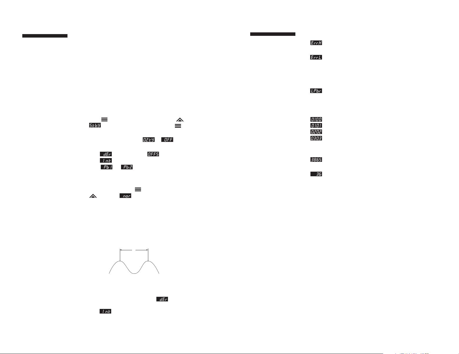
33
Error Codes
If an error code cannot
be cleared by using
the actions provided,
contact factory.
Display Problem Actions
Open Sensor Check sensor,
wiring, and Input.
Reversed Sensor Check the type
selection in
the Input menu,
and check sensor
polarity.
Loop Break Correct problem
and reset
controller.
Checksum Error Press any key
RAM Error to perform a
Defaults Loaded soft reset and
EEPROM Write Failure reinitialize
controller.
Power Fail Resume No further resume
Feature Disabled actions available.
Plus other Unexpected or Reset
2-Digit Invalid Interrupt controllers
Code
7) While monitoring the recording device, decrease the
proportional band value by repeatedly halving the value
until a small, sustained temperature oscillation is
observed. Measure the period of one cycle of oscillation
(“T” on the diagram below).
8) Divide the period of oscillation (T) by eight. The resulting
number is the correct Derivative time in seconds.
Multiply this number by four. This is the correct Integral
time in seconds.
9) Multiply the bandwidth value obtained in Step 7 by 1.66
and enter this as the new proportional band value.
Manual Tuning
Manual Tuning Procedure
(Zeigler-Nichols PID Method)
This tuning method may be used for non-temperature control
processes or if the spread between ambient temperature and
process operating temperature is small. For best results, the
use of a recording device is required when tuning with this
method.
1) For temperature control processes, disable any cooling
device used.
2) With the power off and the controller NOT in the Key
Lockout security level, apply power and immediately put
the controller in Standby mode by pressing the Mode/
Enter key for three seconds, the Raise key until
appears and press the Mode/Enter key again.
3) If you have a direct-acting output, it must be disabled
before proceeding further = .
4) Under the Control menu, make sure that the derivative
term , the offset term , and the integral
term are all set to zero, and the proportional
band or is set to the maximum setting.
5) Adjust setpoint to the desired value with the Raise/Lower
keys.
6) Press the Mode/Enter key for four seconds, the Raise
key twice , and the Mode/Enter key again to
return the controller to normal operation.
While some processes
other than heat or cool
applications may
respond successfully to
autotuning procedures,
the controller may need
to be manually tuned
for non-temperature
processes.
32
T
Page 21

35
Integral 0 to 9600 Seconds
Derivative 0 to 2400 Seconds
Cycle Time 200 ms; 1 to 120 sec
Control Hysteresis 1 to Span of Sensor
Autotune Operator Initiated from
Front Panel
Manual Control Operator Initiated from
Front Panel
Mechanical Characteristics
Display Dual, 4-digit 0.36" (9.2 mm)
LED display
Process Value: Orange
Setpoint Value/Menu: Green
Numeric Range -1999 to 9999
Front-Panel Cutout 1.771" x 1.771"
(45 mm x 45 mm)
Depth Behind Panel 3.937" (100 mm)
Front Panel Rating NEMA 4X
Operating Temperature 32 to 140° F (0 to 60° C)
Humidity Conditions 90% R.H. max.,
non-condensing
Parameter Retention Solid-state, non-volatile
memory
Connections Input and output via barrier
strip with locking terminals
Contacts Twin bifurcated
Technical
Specifications
34
Technical
Specifications
Operating Limits
Ambient Temperature 32°F to 140°F (0°C to 60°C)
Relative Humidity Tolerance 90%, Non-Condensing
Power 100 to 250 V
50/60 Hz (Single-Phase)
100 to 250 Vdc
24 Vac/dc
Power Consumption Less than 6 VA
Performance
Accuracy ±0.20% of Full Scale
(±0.10% Typical), ±1 Digit
Setpoint Resolution 1 Count / 0.1 Count
Repeatability ±1 Count
Temperature Stability 5 µV /°C (Maximum)
TC Cold-End Tracking 0.05°C /°C Ambient
Noise Rejection >100 dB Common Mode,
>70 dB Series Mode
Process Sampling 10 Hz (100 ms)
Control Characteristics
Setpoint Limits Automatically Adjust to
Selected TC/RTD
Alarms Adjustable for High/Low;
Selectable Process, Deviation,
or Band Alarms
Proportional Band 1 to Span of Sensor
Page 22

37
CN8200
Ordering Codes
Ordering Number Description
CN8201 1/16 DIN Single output
CN8202 1/16 DIN Dual output
Output Type - Ordering Suffix
First Output Second Output
Relay -R1 -R2
dc Pulse -DC1 -DC2
1A SSR -T1 -T2
4-20 mA (500 ohm max.) -F1 -F2
4-20 mA (1000 ohm max.) -FH1 -FH2
Optional Power Supply
24 Vac/Vdc -LV
Additional Options (cannot be field-installed)
Description Ordering Suffix
Single alarm relay -AL1
Dual alarms, ac SSR -AL2
Dual alarms, DC 24V -AL3
RS-232 communications -C2
RS-485 communications -C4
RS-485 w/Digital input, switch closed -C4-DIC
RS-485 w/Digital input, switch open -C4-DIO
RS-485 w/Digital input, 5V -C4-DIV
RS-485 communications, MODBUS -C4-MOD
RS-485 MODBUS w/Digital input, switch closed -C4-MOD-DIC
RS-485 MODBUS w/Digital input, switch open -C4-MOD-DIO
RS-485 MODBUS w/Digital input, 5V -C4-MOD-DIV
Process output, 4 to 20 mA -PVSV1
Process output, 0 to 5 Vdc -PVSV2
Digital input, switch closed w/1 alarm -RSP1
Digital input, switch open w/1 alarm -RSP2
Digital input, 5V w/1 alarm -RSP3
Transducer power supply, 15 Vdc -XP1
Transducer power supply, 12 Vdc -XP2
Transducer power supply, 10 Vdc -XP3
Transducer power supply, 5 Vdc -XP4
36
Technical
Specifications
Input Type
Thermocouple B, C, E, J, K, N, NIC, NNM, R, S, T, Platinel II
Maximum lead resistance 100 ohms
for rated accuracy
RTD Platinum 2- and 3-wire, 100 ohms at
0° C, DIN curve standard (0.00385)
1000 ohms available
Linear 0-50 mV/10-50 mV, 0-5 V/1-5 V
0-20 mA/4-20 mA, 0-100 mV, 0-10 V
Output Device
R 5 A (120/240 Vac) relay, normally
open, used for switching resistive loads.
If an “R” output is selected, order
CNQUENCHARC. If relays or solenoids
are to be driven, select the “T” output.
DC 20 Vdc pulsed output for solid-state relays.
T 1 A @ 120/240 Vac , solid-state relay, zero
voltage-switched and optically isolated from
drive signal. Only resistive loads to 1A may
be controlled directly. Larger loads may be
controlled using an external contactor.
F 4-20 mA, full output to load with 500 ohm
impedance max.
FH High impedance 4-20 mA (1000 ohms max.)
Page 23
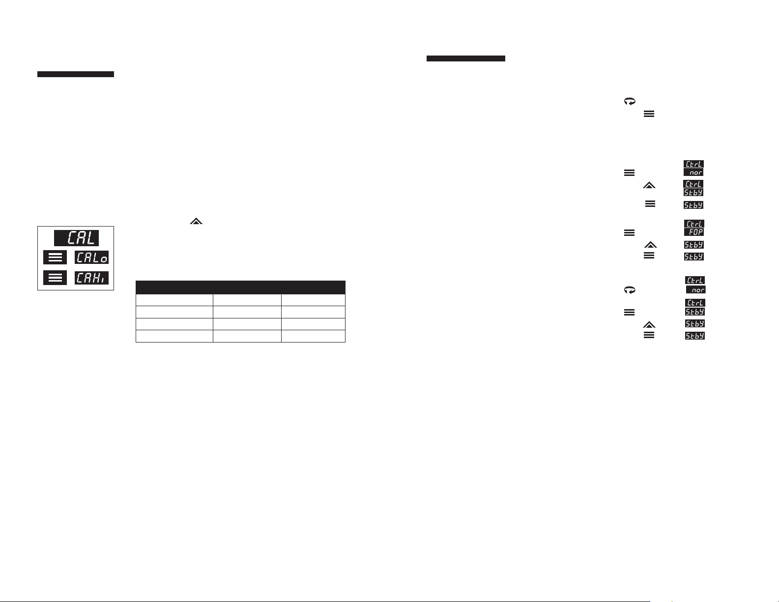
39
Quick-Helps
1. To return the unit to last operating mode
(Normal, Standby, FOP, or Tune):
Action Display
From Menu System: Press and hold PV + SV + Mode
for 3 sec.
From Security Level Menu: Press PV+ SV + Mode
2. To enter Standby
operating mode:
Action Display
From Normal Press and hold
operating mode:
for 3 sec.
Press
Press + PV + SV
From FOP (Manual) Press and hold
operating mode:
for 3 sec.
Press
Press + PV + SV
From Menu System: Press and hold
for 3 sec.
Press and hold
for 3 sec.
Press
Press + PV + SV
38
The Series CN8200
controller is precalibrated at the factory.
Under normal circumstances, the factory
calibration should be
valid for the life of
the instrument. If
recalibration should
be required, allow
the controller to warm
up for 15 minutes
and follow these steps
carefully.
Recalibration
Procedures
1) Remove power from the controller and disconnect all
output devices. Disconnect input. Attach an appropriate
calibrator to the input terminals.
2) Apply power to the calibrator, making sure that the
displayed value is not outside the range of the controller.
Then, apply power to the controller.
3) Index to the Calibration Low menu item in the Calibration
Menu.
(You must have Security Level set to “Factory” to access this menu.)
4) Dial Calibrator to prompted value on the controller’s
display. See chart below for RTD resistance vs.
temperature values.
5) Allow the controller to settle for at least one minute.
6) Press Raise Key.
7) Repeat Steps 4, 5, and 6 for the Calibration High setting.
8) Press the Menu Access key for three seconds to return to
the Process Value display.
RTD Calibration Values
Degrees (C) Degrees (F) Ohms
0°
768°
328°
32°
1414°
622.4°
100 Ω
366 Ω
222 Ω
Page 24
41
IEC
Requirements
The maximum supply current is line voltage dependent:
230 mA for a 24 Vac/dc input fuse rating=700 mA
60 mA for an 85-250 Vac input fuse rating=100 mA
Output Specifications
Output Type Max current Voltage Leakage
R 5 A 250 Vac 1000 M ohms
T 1 A 250 Vpk 1 mA
DC 20 mA 5 V NA
CLEANING INSTRUCTIONS
1. Remove power from the unit prior to any cleaning operation.
2. Use a cotton cloth to gently and sparingly apply isopropyl
alcohol only. Do not use cleaners or other solvents as they may
damage the unit.
3. Allow the unit to dry completely prior to reapplying power.
USE OF THIS EQUIPMENT IN A MANNER NOT SPECIFIED BY
THE MANUFACTURER MAY IMPAIR PROTECTION PROVIDED
BY THE EQUIPMENT!
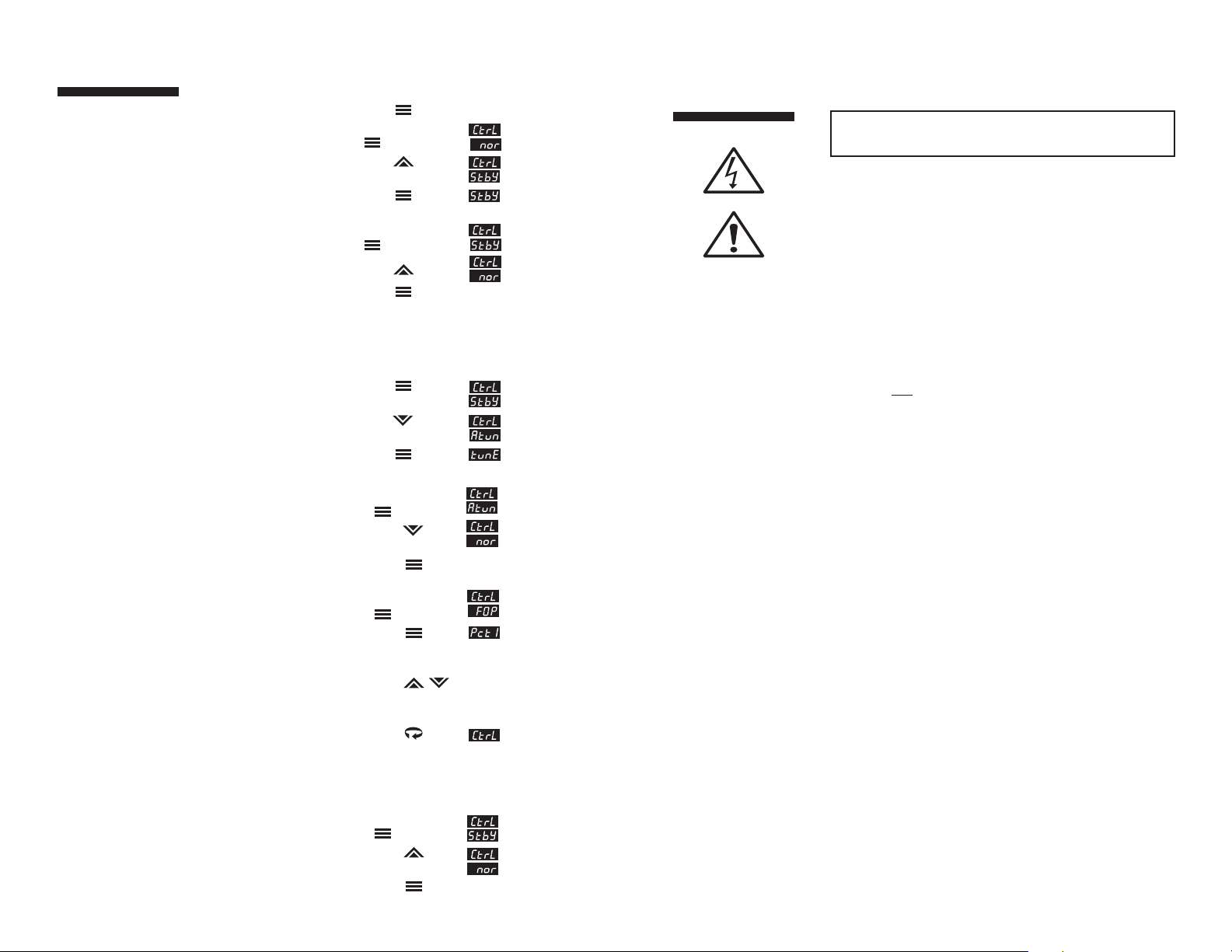
5. To abort Autotuning Action Display
and return to normal Press and hold
operation: for 3 sec.
Press
Press PV + SV
6. To enter FOP (Manual) Action Display
operating mode:
Press and hold
for 3 sec.
Press + PV +
% of Power
Value
Press
to set new
% of Power Value
Press to + PV +
set % of Power % of Power
for Output 2 Value
if desired.
7. To escape from FOP Action Display
(Manual) operating mode:
Press and hold
for 3 sec.
Press
Press PV + SV
40
Quick-Helps
2. To enter Standby operating mode: (cont.)
From Security Level Menu: Press PV + SV
Press and hold
for 3 sec.
Press
Press + PV + SV
3. To escape from Standby Action Display
operating mode:
Press and hold
for 3 sec.
Press
Press PV + SV
4. To initiate Autotuning: Action Display
Enter Standby
operating mode
(See Quick-Help #2)
Press
Press
Press + PV + SV
Page 25

43
Loop Break Time - the time interval from when the controller detects a loop
break condition and the initiation of the failsafe state.
Lowest Reading - records the lowest process value read by the controller. May
be reset to zero by using the Raise or Lower arrow keys.
Lower Setpoint Limit - prohibits users from adjusting the setpoint lower than
the selected value.
Manual Reset - an adjustment that moves the Proportional Band up or down by
a fixed percentage so that more or less power is applied at setpoint. It is used
to eliminate offset error.
On/Off Output Type - In a heating application, the controller applies 100%
output power if the process temperature is below the setpoint and 0% at the
setpoint. For a cooling application, the controller applies 100% output power if
the process temperature is above the setpoint and 0% output power at the
setpoint. There are only two output states: fully on and fully off.
Applications for On/Off Control:
1. When temperature oscillation is acceptable.
2. When constant cycling of mechanical devices is
prohibited (Compressors, Blowers, etc.)
3. Under-powered processes
Output Low Limit % - Prohibits the controller’s output from going
below the specified percentage.
Output High Limit % - Prohibits the controller’s output from going above the
specified percentage.
PID Output Type (Proportional - Integral - Derivative) - The controller
modulates output power by adjusting the output power percentage within a
proportional band. Power is proportionally reduced as the process temperature
gets closer to the setpoint temperature. PID control helps reduce overshoot on
start-up, enhances stability, and compensates for process lag. The PID
parameters are automatically calculated for a particular application during the
autotune procedure.
Applications for PID Control:
1. Where process temperature lags exist
2. When load changes are present
3. When overshoot is prohibited
4. When very accurate control is required
Proportional Band - the band (expressed in degrees of temperature) in which
the controller modulates its power percentage.
Temperature Lag - The product of thermal resistance and thermal capacity.
Also defined as delay of the transmission of heat from the controlled element
to the sensor caused by thermal mass of the process material and/or process
container, or the distance between the control element and the sensor.
Upper Setpoint Limit - prohibits users from adjusting the setpoint higher than
the selected value.
42
Alarm Delay - the time delay between the detection of the alarm condition and
the initiation and indication of the output action.
Alarm Inhibit - prevents low setpoint alarm activation during cold startup
applications.
Bias - allows the operator to compensate for any difference between sensor
temperature and the point to be measured. The process display and setpoint
will be offset by the value entered in the Bias parameter in the input menu. Ex:
Desired temperature is 150 degrees. Sensor is adjacent to heater and reads 50
degrees higher than the actual process temperature. Enter bias of -50. Enter
setpoint of 150. Process will display 150 even though sensor will be
measuring 200 degrees.
Blanking - controls the time the setpoint value display remains on. After the set
time, the setpoint value display turns off. Pressing any button causes the
setpoint value display to reappear for the selected time interval.
Cycle Time - The period of time in which the controller’s output completes an
on-off cycle (Proportional Output Type only).
Example: Output type = Mechanical relay
Cycle time = 10 seconds
Output power = 50%
Controller output = 5 seconds closed,
5 seconds open
Deadband - In On/Off temperature control, it is the band above or below the
setpoint where there is no output action. It has the effect of moving the
apparent setpoint.
Derivative (rate) - Adjusts the controller gain quickly in response to load
changes.
Failsafe State - designates the percentage of power output that the controller
defaults to after it detects a loop break condition and after the loop break time
has elapsed.
Filter (in Display menu) - changes the filtering speed for the process value
display only. It does not affect control. This parameter is mainly used to slow
down the flickering of the display when the decimal position chosen is greater
than zero.
Filtering (in Input menu) - sets the time period over which the process value is
averaged.
Highest Reading - records the highest process value read by the controller. It
may be reset to zero by using the Raise or Lower arrow keys.
Hysteresis - In On/Off temperature control, hysteresis represents the band
where the output changes state from deactivated to activated. It prevents
chattering around the setpoint and prevents rapid output cycling.
Integral (automatic reset) - slowly adjusts the position of the Proportional
Band (range of power output) to eliminate offset error.
Loop Break - a condition where the input is not changing or responding
properly to the output action. This could be caused by a thermocouple or input
failure, or a heater or load failure.
Glossary Glossary
Page 26

45
5. Press again to display the Output 1 Cycle Time parameter. Select the desired cycle time according to
the output device used. If unsure, refer to the ordering code on page 37 of the instruction manual and compare
it to the number on the label.
Recommended cycle times are:
For Control Output Device — Select Cycle Time (in seconds)
R 15 to 120
F 0.2
FH 0.2
DC 0.2
T 15 to 120
IMPORTANT: IF ONLY ONE OUTPUT IS
PID
, SET THE OTHER OUTPUT TO EITHER
ON/OFF, ALARM
, OR
OFF
.
6. Press the key to display the next output parameter, and select the desired value using the or keys.
7. Press to select other Output Type following steps 4 to 6.
8. Press the repeatedly until is displayed, then press and make sure autotune damping
parameter is set to the proper setting for your application. See page 37 for more information.
9. Press and hold key for approximately 3 seconds until upper display flashes and Process Value.
10. Press the or keys adjust setpoint to desired value.
11. Press and hold key for 3 seconds. Lower display will indicate . Press or key until
is displayed. Press to initiate autotuning. Display will flash . After autotune is complete,
the display stops flashing, and the controller will revert to Process Value display and begin controlling the
process.
12. If unacceptable overshoot occurs, change damping setting to high , or if response is sluggish, change
damping setting to low .
Quick Setup Instructions - Series CN8200 Temperature Controller
Experienced users, already familiar with the Series CN8200, and using the
controller with PID outputs, may follow these condensed instructions to
autotune the controller and get started quickly once the instrument is properly
mounted and wired, and the Security Level is set to . Once setup is
complete, we recommend changing the Security Level back to the most
restrictive level suitable for your application.
These quick setup instructions are not meant as a substitute for reading the full
instruction manual supplied with the controller. Please be sure to read through the manual for specific
details of operation and, most importantly, for safety precautions. If you have any questions, or
experience problems with setting up your controller, consult the full instruction manual first and, if
you still need assistance, contact Omega at 1-800-622-2378.
Menu Access Raise Lower Mode/Enter
1. Apply power. After self-check display stops, place controller in Standby mode by pressing and holding the
Mode/Enter key for 3 seconds, the or key until appears, and then the key again.
will flash, alternating with the Process Value.
2. Press and hold the Menu Access key for 3 seconds until is displayed. Press key once until
appears, then use or keys to select sensor input type.
3. Press to display . Then press once to display . Use or to select .
4. Press the key until Output 1 Action is displayed. Select the desired output action using the
or keys. (Reverse = Heating)
44
Page 27

M2942/121905
Where Do I Find Everything I Need for
Process Measurement and Control?
OMEGA…Of Course!
Shop online at www.omega.com
TEMPERATURE
3
Thermocouple, RTD & Thermistor Probes, Connectors,
Panels & Assemblies
3
Wire: Thermocouple, RTD & Thermistor
3
Calibrators & Ice Point References
3
Recorders, Controllers & Process Monitors
3
Infrared Pyrometers
PRESSURE, STRAIN AND FORCE
3
Transducers & Strain Gages
3
Load Cells & Pressure Gages
3
Displacement Transducers
3
Instrumentation & Accessories
FLOW/LEVEL
3
Rotameters, Gas Mass Flowmeters & Flow Computers
3
Air Velocity Indicators
3
Turbine/Paddlewheel Systems
3
Totalizers & Batch Controllers
pH/CONDUCTIVITY
3
pH Electrodes, Testers & Accessories
3
Benchtop/Laboratory Meters
3
Controllers, Calibrators, Simulators & Pumps
3
Industrial pH & Conductivity Equipment
DATA ACQUISITION
3
Data Acquisition & Engineering Software
3
Communications-Based Acquisition Systems
3
Plug-in Cards for Apple, IBM & Compatibles
3
Datalogging Systems
3
Recorders, Printers & Plotters
HEATERS
3
Heating Cable
3
Cartridge & Strip Heaters
3
Immersion & Band Heaters
3
Flexible Heaters
3
Laboratory Heaters
ENVIRONMENTAL
MONITORING AND CONTROL
3
Metering & Control Instrumentation
3
Refractometers
3
Pumps & Tubing
3
Air, Soil & Water Monitors
3
Industrial Water & Wastewater Treatment
3
pH, Conductivity & Dissolved Oxygen Instruments
46
OMEGA’s poli cy is to mak e r unni ng ch anges, not mod el chan ge s, whe ne ver an impr ovem en t is poss ible .
This affords our customers the latest in technology and engineering.
OMEGA is a registered trademark of OMEGA ENGINEERING, INC.
© Copyright 2004 OMEGA ENGINEERING, INC. All rights reserved. This document may not be copied, photocopied,
reproduced, translated, or reduced to any electronic medium or machine-readable form, in whole or in part, without the
prior written consent of OMEGA ENGINEERING, INC.
WARRANTY/DISCLAIMER
OMEGA ENGINEERING, INC. warrants this unit to be free of defects in materials and workmanship for
a period of 13 months from date of purchase. OMEGA’s Warranty adds an additional one (1) month
grace period to the normal one (1) year product warranty to cover handling and shipping time. This
ensures that OMEGA’s customers receive maximum coverage on each product.
If the unit malfunctions, it must be returned to the factory for evaluation. OMEGA’s Customer Service
Department will issue an Authorized Return (AR) number immediately upon phone or written request.
Upon examination by OMEGA, if the unit is found to be defective, it will be repaired or replaced at no
charge. OMEGA’s WARRANTY does not apply to defects resulting from any action of the purchaser,
including but not limited to mishandling, improper interfacing, operation outside of design limits,
improper repair, or unauthorized modification. This WARRANTY is VOID if the unit shows evidence of
having been tampered with or shows evidence of having been damaged as a result of excessive
corrosion; or current, heat, moisture or vibration; improper specification; misapplication; misuse or
other operating conditions outside of OMEGA’s control. Components which wear are not warranted,
including but not limited to contact points, fuses, and triacs.
OMEGA is pleased to offer suggestions on the use of its various products. However, OMEGA neither
assumes responsibility for any omissions or errors nor assumes liability for any damages that result
from the use of its products in accordance with information provided by OMEGA, either verbal or
written. OMEGA warrants only that the parts manufactured by it will be as specified and free of defects.
OMEGA MAKES NO OTHER WARRANTIES OR REPRESENTATIONS OF ANY KIND WHATSOEVER,
EXPRESS OR IMPLIED, EXCEPT THAT OF TITLE, AND ALL IMPLIED WARRANTIES INCLUDING ANY
WARRANTY OF MERCHANTABILITY AND FITNESS FOR A PARTICULAR PURPOSE ARE HEREBY
DISCLAIMED. LIMITATION OF LIABILITY: The remedies of purchaser set forth herein are exclusive,
and the total liability of OMEGA with respect to this order, whether based on contract, warranty,
negligence, indemnification, strict liability or otherwise, shall not exceed the purchase price of the
component upon which liability is based. In no event shall OMEGA be liable for consequential,
incidental or special damages.
CONDITIONS: Equipment sold by OMEGA is not intended to be used, nor shall it be used: (1) as a
“Basic Component” under 10 CFR 21 (NRC), used in or with any nuclear installation or activity; or (2)
in medical applications or used on humans. Should any Product(s) be used in or with any nuclear
installation or activity, medical application, used on humans, or misused in any way, OMEGA assumes
no responsibility as set forth in our basic WARRANTY / DISCLAIMER language, and, additionally,
purchaser will indemnify OMEGA and hold OMEGA harmless from any liability or damage whatsoever
arising out of the use of the Product(s) in such a manner.
RETURN REQUESTS/INQUIRIES
Direct all warranty and repair requests/inquiries to the OMEGA Customer Service Department. BEFORE
RETURNING ANY PRODUCT(S) TO OMEGA, PURCHASER MUST OBTAIN AN AUTHORIZED RETURN (AR) NUMBER
FROM OMEGA’S CUSTOMER SERVICE DEPARTMENT (IN ORDER TO AVOID PROCESSING DELAYS). The
as si gne d AR number sho uld the n be mar ked on the out si de of the retur n pa cka ge and on any
correspondence.
The purchaser is responsible for shipping charges, freight, insurance and proper packaging to prevent
breakage in transit.
FOR WARRANTY
RETURNS, please have the
following information available BEFORE
contacting OMEGA:
1. Purchase Order number under which
the product was PURCHASED,
2. Model and serial number of the product under
warranty, and
3. Repair instructions and/or specific
problems relative to the product.
FOR NON-WARRANTY REPAIRS,
consult OMEGA for
current repair charges. Have the following
information available BEFORE contacting OMEGA:
1. Purchase Order number to cover the
COST of the repair,
2. Model and serial number of the
product, and
3. Repair instructions and/or specific problems
relative to the product.
 Loading...