

Page 1
omega.com
®
®
User’s Guide
www.omega.com
e-mail: [email protected]
CN8200 SERIES
Communications & Options Guide
TM
Page 2

omega.com
®
®
TM
OMEGAnet® On-Line Service
USA: ISO 9001 Certified
One Omega Drive, Box 4047
Stamford CT 06907-0047
Tel: (203) 359-1660
FAX: (203) 359-7700
e-mail: [email protected]
www.omega.com [email protected]
Internet e-mail
Canada:
976 Bergar
Laval (Quebec) H7L 5A1
Tel: (514) 856-6928
FAX: (514) 856-6886
e-mail: [email protected]
For immediate technical or application assistance:
USA and Canada:
Sales Service: 1-800-826-6342 / 1-800-TC-OMEGA
Customer Service: 1-800-622-2378 / 1-800-622-BEST
Engineering Service: 1-800-872-9436 / 1-800-USA-WHEN
TELEX: 996404 EASYLINK: 62968934 CABLE: OMEGA
®
®
Mexico:
Tel: (001) 800-826-6342
FAX: (001) 203-359-7807
®
En Espan~ol: (001) 203-359-7803
e-mail: [email protected]
Servicing Europe:
Benelux:
Postbus 8034, 1180 LA Amstelveen
The Netherlands
Tel: (31) 20 6418405 FAX: (31) 20 6434643
Toll Free in Benelux: 0800 0993344
e-mail: [email protected]
Czech Republic:
Rudé armády 1868, 733 01 Karviná 8
Tel: 420 (69) 6311899 FAX: 420 (69) 6311114
Toll Free: 0800-1-66342 e-mail: [email protected]
France:
9, rue Denis Papin, 78190 Trappes
Tel: (33) 130-621-400 FAX: (33) 130-699-120
Toll Free in France: 0800-4-06342
e-mail: [email protected]
It is the policy of OMEGA to comply with all worldwide safety and EMC/EMI regulations that apply. OMEGA is constantly pursuing certification of
its products to the European New Approach Directives. OMEGA will add the CE mark to every appropriate device upon certification.
The information contained in this document is believed to be correct, but OMEGA Engineering, Inc. accepts no liability for any errors it contains,
and reserves the right to alter specifications without notice.
WARNING: These products are not designed for use in, and should not be used for, patient-connected applications.
2
Germany/Austria:
Daimlerstrasse 26, D-75392
Deckenpfronn, Germany
Tel: 49 (07056) 3017 FAX: 49 (07056) 8540
Toll Free in Germany: 0800 TC-OMEGA
e-mail: [email protected]
United Kingdom: ISO 9002 Certified
One Omega Drive
River Bend Technology Centre
Northbank, Irlam
Manchester M44 5EX England
Tel: +44 (0)161 777 6611
FAX: +44 (0)161 777 6622
Freephone: 0800-488-488
e-mail: [email protected]
SM
Table of
Contents
For information and
instructions related to
basic operations, refer
to the Series CN8200
operator’s manual
supplied with your
controller.
Options Wiring Diagrams
Dual Alarm Outputs (Options -AL2) 4
Dual 24 Volt DC Alarm Outputs (Option -AL3) 5
Relay, N.O. Alarm Output (Option -AL1) 6
RS-232 Communications (Option -C2) 7
RS-485 Communications (Option -C4) 8
Contact/Digital Input with Alarm
(Options -RSP1, -RSP2, -RSP3 ) 10
Transducer Excitation (Options XP1, -XP2,
-XP3, -XP4) 12
Process Output (Options -PVSV1, -PVSV2) 13
Guide to Digital Communications
Remote Communications Options 15
Omega+ Protocol 17
- Message Format 19
- Sample Commands 24
- Request Messages 25
- Response Messages 29
- Communications Parameter List 33
- Auxiliary Commands 37
- Communications Error Codes 40
3
Page 3
5
Dual Alarm
1 AMP FUSE
LOAD
3
1
2
4
5
6
7
8
9
10
13 14
1211
1 AMP FUSE
LOAD
20 - 240 VAC
TYPICAL
OUTPUT
CONNECTION
20 - 30 VAC
FIELD CONNECTIONS
3
1
2
4
5
6
7
8
9
10
13 14
1211
TYPICAL
CONNECTION
USING PIEZOELECTRIC
AUDIBLE ALARM DEVICE
FIELD
CONNECTIONS
MANUFACTURED WITH DUAL
24 VDC ALARM
OPTION BOARD.
PART #785A270U02
13 7
14
6
CONTROLLER 24V OUTPUT
CONFIGURATION
25 V
1K
SONALERT
LED
INDICATOR
TYPICAL CONNECTION
USING LED INDICATOR
WITHOUT LIMITING
RESISTOR
Outputs
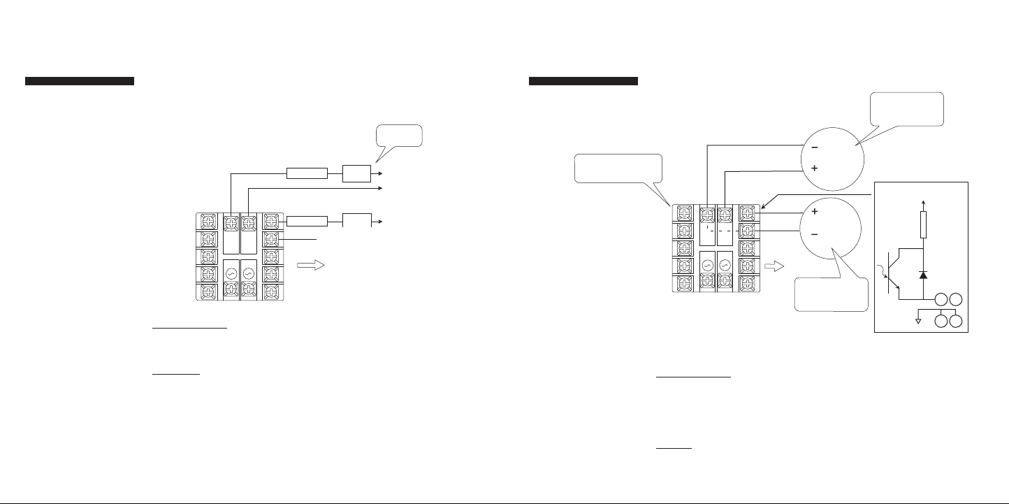
Option -AL2: Dual Alarm Output, N.O.
This optional hardware module provides two alarm drive outputs. LED indicators A1 and A2 are used to indicate alarm conditions as configured in the Alarm
Menu.
Dual 24 Vdc
Alarm Outputs
Option -AL3: Dual 24 Vdc Alarm Outputs
4
Option Description:
Option -AL2: Dual alarm, N.O.
Load Limits:
Max. Load Current 1 A rms
Min. Load Current 0.5 mA rms
Power Factor Range 0.2 to 1.0 (can drive small
motors, solenoids, valves, and
contactors)
Max. Surge Current
Non-repeating for 1 second 7.5 A
Max. I2T for fusing (0.01 sec) 4.5 amp-squared seconds (1 A -
ABC1 typical fuse)
Option Description: Dual 24 V outputs with clamping diodes
Pins 13 & 7 are connected internally
Source current is limited to 25 mA (1000 ohm
resistor)
Open circuit voltage is 25 volts
Isolation: Isolation 300 volts ac/dc either output to
instrument
Page 4
6
7
Relay, N.O.
3
1
2
4
5
6
7
8
9
10
13 14
1211
5 AMP FUSE
LOAD
SUPPLY
VOLTAG
E
FIELD CONNECTIONS
3
1
2
4
5
6
7
8
9
10
13 14
1211
FIELD CONNECTIONS
COMPUTER
2 TX
3 RX
7
50 FEET OR LESS
D-SUB STYLE 25 PIN MALE
RX
TX
GND
Alarm Output
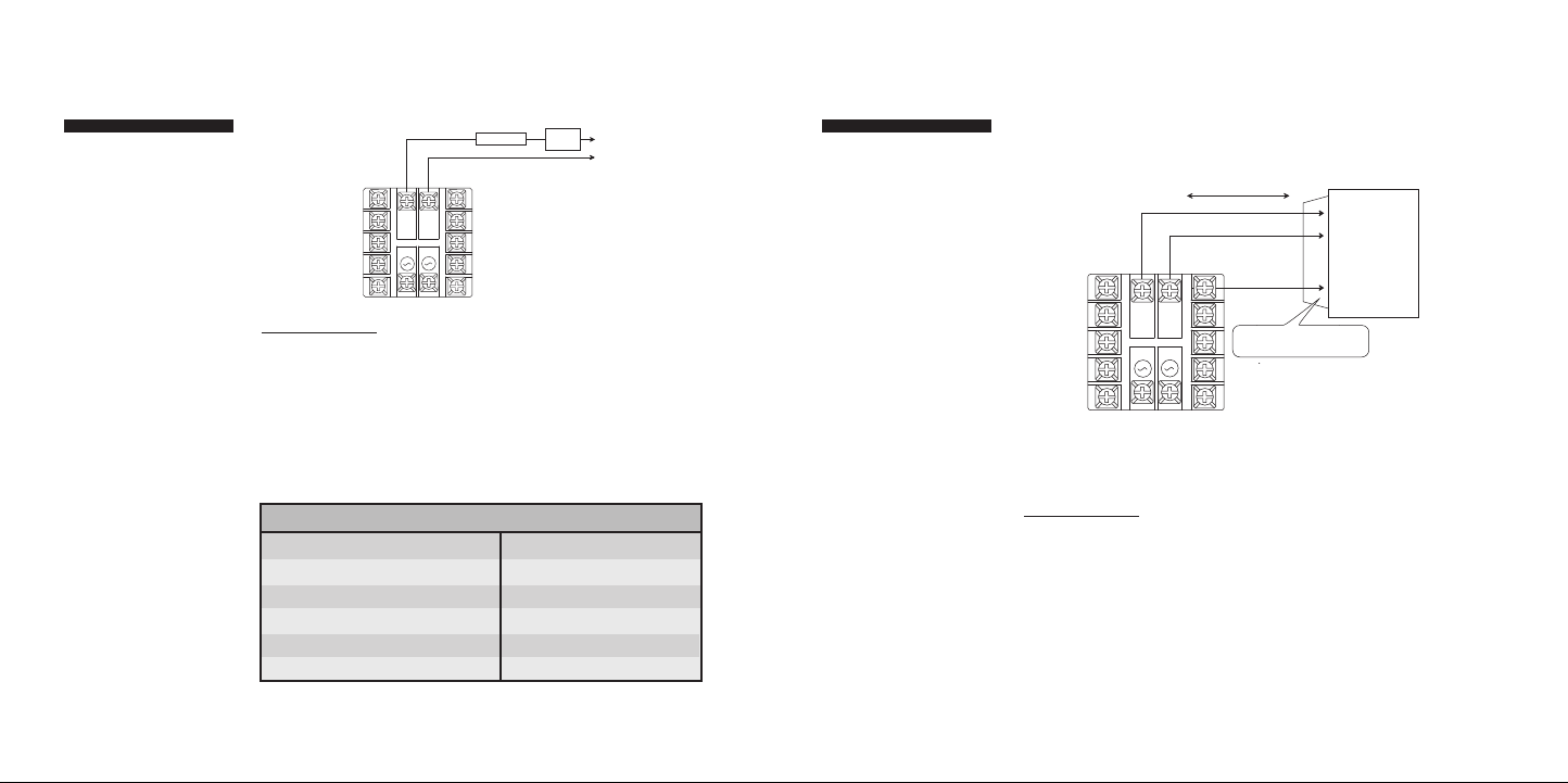
Option -AL1: Relay, N.O. Alarm Output
*
*
Option Description: NO (Normally open) relay contact is closed when
either alarm is active. Jumpers on the board can be
removed to activate the output for a single alarm only:
JP1 - Alarm A1
JP2 - Alarm A2
The relay life is greater than 100,000 operations at 5 operations per second
switching full load.
Connect load and supply voltage per the following table:
*
Load Type 5 Amp Voltage Limit
Resistive DC 30 Vdc
Inductive DC (L/R = 7 ms) 20 Vdc
Resistive AC 250 Vac
Inductive AC (pF = 0.4) 150 Vac
Motor, AC, 1/6 hp 250 Vac
Tungsten Lamp, 360 W 120 Vac
RS-232
Communications
Option -C2: RS-232 (one-to-one)
Communications
Option Description: Provides a one-to-one connection between
the controller and an RS-232 port.
Computers, PLCs, or dumb terminals may
be used to set and access controller data.
Page 5
8
9
RS-485
3
1
2
4
5
6
7
8
9
10
13 14
1211
FIELD CONNECTIONS
COMPUTER
UP TO 4000 FEET
DATA CABLE ASSEMBLY
DB25 MALE/MALE
RS- 485/ RS-2 32
CON VERT ER ( Athe na
P/N 223 C001 U03 )
*
TO CONTROLLER TERMINAL 13
TO
CONTROLLER TERMINAL 14
(-)
(+)
D-SUB STYLE 25 PIN FEMALE
SOLDER PIN CONNECTOR
13 14
13 14
13 14
120 OHMS
TO
PINS 13 AND 14
LAST CONTROLLER TERMINATION
(UP TO 32 CONTROLLERS)
2
5
14
7
OPTION 42
3
1
2
4
5
6
7
8
9
10
13 14
1211
FIELD CONNECTIONS
3
1
2
4
5
6
7
8
9
10
13 14
1211
20 - 240 Vac
1 AMP FUSE ALARM LOAD
OPTIONS 40 AND 41
OR
5V @ 10 mA max.
(-)
(+)
Communications
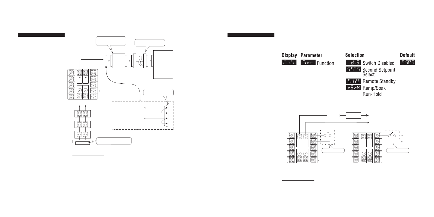
Option -C4: RS-485 (one-to-many)
Communications
Option Description: Provides one-to-many communications.
If run exceeds 1000 ft., terminate the controller furthest from the computer by
connecting a 120-ohm, 1/4-watt resistor between terminals 13 and 14.
*Converter is supplied with a wallplug-mount power transformer.
Contact/Digital
Contact/Digital
Input with Alarm
Input with Alarm
Options -RSP1, -RSP2, -RSP3 Remote Setpoint
Switch, with Alarm (Contact Digital Input)
Input Option Menu
Option Description: Dual function board (functions unrelated)
a. Output alarm is energized when either A1
b. Digital input controls Remote Standby, Ramp-
or A2 is active.
Soak Run/Hold, OR Second Setpoint Select.
Page 6
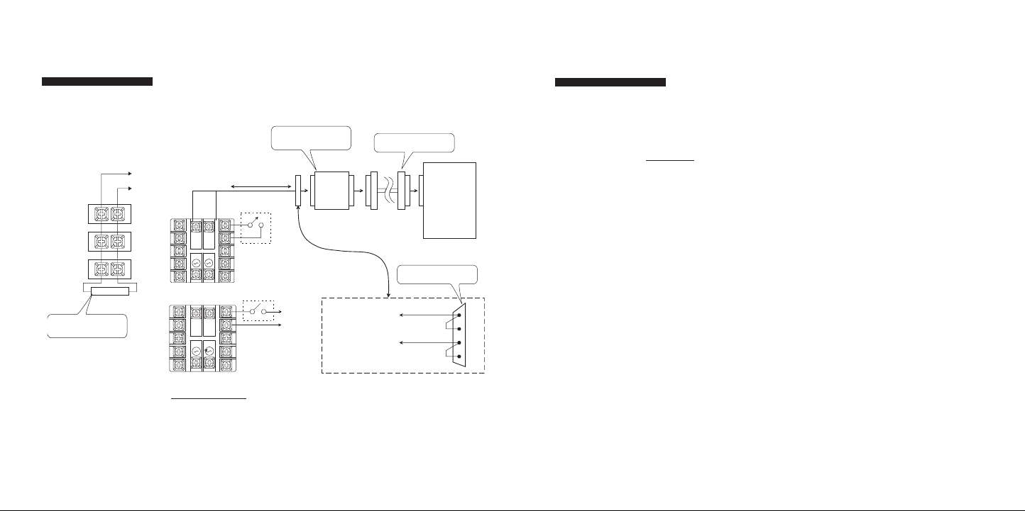
10
RS-485
COMPUTER
UP TO 4000 FEET
RS232
DATA
CABLE ASSEMBLY
DB25 MALE/MALE
RS- 485/ RS- 232
CON VERT ER
*
TO CONTROLLER TERMINAL 13
TO
CONTROLLER TERMINAL 14
(-)
(+)
D-SUB STYLE 25 PIN FEMALE
SOLDER PIN CONNECTOR
13 14
13 14
13 14
120 OHMS
TO
PINS 13 AND 14
2
5
14
7
LAST CONTROLLER TERMINATION
(UP TO 32 CONTROLLERS)
3
1
2
4
5
6
7
8
9
10
13 14
1211
3
1
2
4
5
6
7
8
9
10
13 14
1211
5V @ 10 mA max.
(-)
(+)
OR
Communications
Options -C4-DIC, -C4-DIO, -C4-DIV, -C4-MOD,
-C4-MOD-DIC, -C4-MOD-DIO, -C4-MOD-DIV:
Digital Input plus RS-485 Communications
Options -C4-DIC, -C4-DIO,
-C4-MOD-DIC, -C4-MOD-DIO
Contact/Digital
Contact/Digital
Input with Alarm
Input with Alarm
Option -RSP1: Active when switch closed.
Option -RSP2: Active when switch open.
Option -RSP3: Active when 5 V input present
Load Limits:
Max. Load Current: 1 A rms
Min. Load Current: 0.5 mA rms
Power Factor Range: 0.2 to 1.0 (can drive small motors, solenoids, valves,
and contactors)
Max. Surge Current,
Non-Repeating for
1 second: 7.5 A
Max. I2T for fusing (0.01 sec): 4.5 amp-squared secs (1A - ABC1
typical fuse)
Note: See previous
page for control input menu selections
Options -C4-DIV,
Option Description: Provides one-to-many communications.
If run exceeds 1000 ft., terminate the controller furthest from the computer by
connecting a 120-ohm, 1/4-watt resistor between terminals 13 and 14.
*Converter is supplied with a wallplug-mount power transformer.
-C4-MOD-DIV
11
Page 7
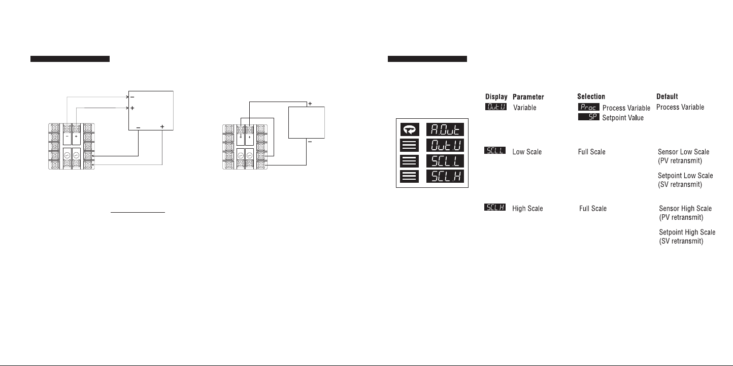
Transducer
3
1
2
4
5
6
7
8
9
10
13 14
1211
RELATIVE
HUMIDITY
SENSOR
(6 - 30 Vdc INPUT)
0 - 1 VOLT OUT
Excitation
Option -XP1, -XP2, -XP3, -XP4: Transducer
Excitation
OR
Auxiliary OutputAuxiliary Output
Option -PVSV1, -PVSV2: Process Output
Option Menu
Option Description: The transducer excitation option provides power to
remote transducers. The transducer outputs, in turn,
provide a signal to the controller input which can be
scaled in the appropriate engineering units.
Option -XP1: 15 Vdc
Option -XP2: 12 Vdc
12
Option -XP3: 10 Vdc
Option -XP4: 5 Vdc
All options will provide at least 20 mA. The transducer circuitry is thermally
protected from short circuits.
13
Page 8
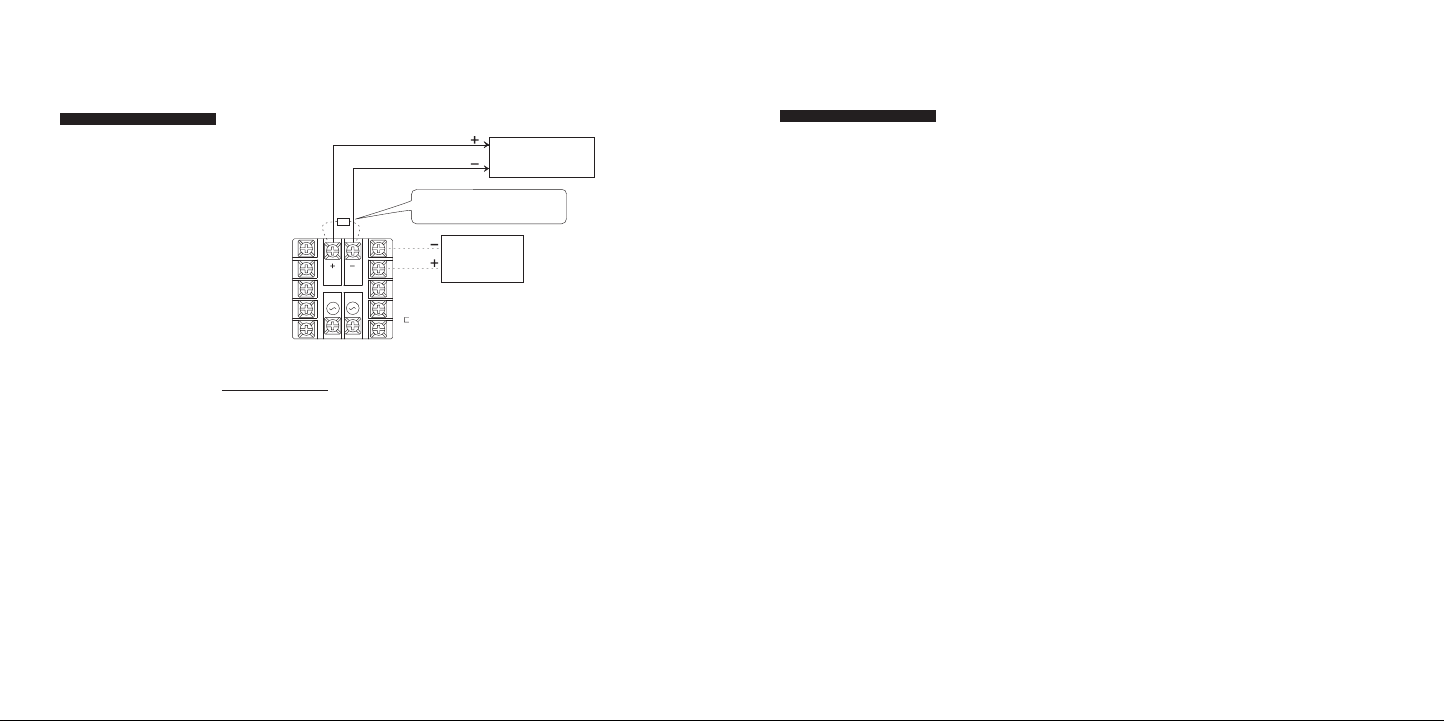
14
15
Auxiliary OutputAuxiliary Output
3
1
2
4
5
6
7
8
9
10
13 14
1211
FIELD CONNECTIONS
4/20 mA REMOTE INDICATOR
0/20 mA REMO
TE INDICATOR
(OPTION 60 AND 62)
200 OHM RESISTOR MUST BE
CONNECTED BETWEEN PINS 13 & 14
FOR VOLTAGE OPTIONS (OPTIONS 61 & 63)
1 - 5 V INDICATOR
0 - 5 V INDICATOR
(OPTION 61 & 63)
Option -PVSV1, -PVSV2: Auxiliary Output
(Option -PVSV1)
(Option -PVSV1)
Option Description: The Setpoint Variable or Process Variable is
Option -PVSV1: 4-20 mA
Option -PVSV2: 0-5 V
The output signal is scalable in the Auxiliary Output Menu. Multiple remote
indicators may be driven by the controller.
For current (mA) options, the remote indicators are connected in series. The
sum of the input resistance for all remote indicators must be less than 400
ohms. For voltage options, the remote indicators are connected in parallel.
The sum of the currents for all remote indicators must be less than 10 mA.
transmitted to a remote device (chart recorders,
indicators, data recorders, computers, process
controllers, etc.) with 1 of 4 different interfaces:
Digital
Communications
Option
Three remote communications options
are available for the
CN8200 which allow
interfacing to remote
devices utilizing the
most common industry
standards: RS232 and
RS485.
Remote Communications Options
RS-232
This method allows bidirectional data transfer via a threeconductor cable consisting of signal ground, receive input
and transmit output. It is recommended for communication
distances less than 50 feet between the computer terminal
and the instrument. Note: Multiple instruments cannot be
connected to the same port.
The RS232 port is optically isolated to eliminate ground
loop problems. Typically, “Data Out” of the computer/
terminal connects to the “RCV” terminal. “Data In” connects
to the “XMT” terminal. If shielded cable is used, it should be
connected to the frame ground at one end only. Signal ground
is to be connected at appropriate ground terminals (refer to
wiring diagram on next page).
RS-485
The RS485 multipoint capability allows up to 32 controllers to
be connected together in a half-duplex network or up to 100
controllers with an appropriate communications repeater.
Page 9
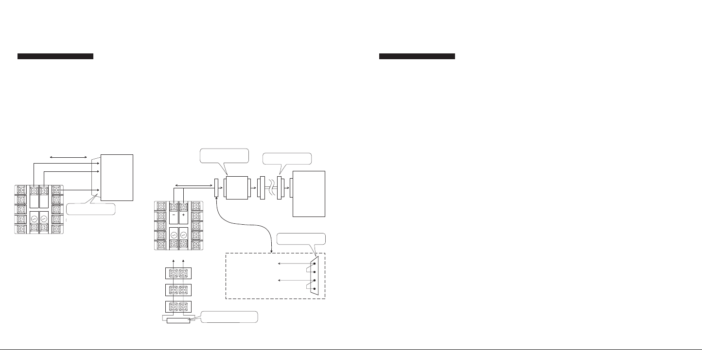
16
17
Digital
3
1
2
4
5
6
7
8
9
10
13 14
1211
FIELD CONNECTIONS
COMPUTER
2 TX
3 RX
7
50 FEET OR LESS
D-SUB STYLE 25 PIN MALE
RX
TX
GND
3
1
2
4
5
6
7
8
9
10
13 14
1211
FIELD CONNECTIONS
COMPUTER
UP TO 4000 FEET
DATA CABLE ASSEMBLY
DB25 MALE/MALE
RS- 485/ RS-2 32
CON VERT ER ( Athe na
P/N 223 C001 U03 )
*
TO CONTROLLER TERMINAL 13
TO CONTROLLER TERMINAL 14
(-)
(+)
D-SUB STYLE 25 PIN FEMALE
SOLDER PIN CONNECTOR
13 14
13 14
13 14
120 OHMS
TO
PINS 13 AND 14
LAST CONTROLLER TERMINATION
(UP TO 32 CONTROLLERS)
2
5
14
7
Communications
Option
Note: Call factory for
a recommended RS485
converter.
Figure 1a. Wiring diagram for
RS-232 digital communications.
This method allows bidirectional data transfer over a twisted pair cable. The
twisted pair cable is a transmission line; therefore, terminating resistors are
required at the most distant ends of the line to minimize reflections (typically
120 ohms at each end). The RS485 circuit is fully optically isolated, eliminating
ground loop problems. Parallel drops from the transmission lines should be
kept as short as possible; however, the line may be daisy-chained at each controller. The polarity of the line is important and each device will specify an “A”
(+) and “B” (-) connection.
Figure 1b. Wiring diagram for
RS-485 digital communications.
Digital
Communications
Option
Omega+ Protocol
The Omega+ Protocol provides an easy way to query and
modify controller parameters using a personal computer and
the optional digital communications option of the CN8200.
In this manual, the word “host” refers to the personal com-
puter that’s communicating with the controllers in the serial
link, and the word “slave” refers to the controllers themselves.
All transactions between the host and the slaves are done
with messages consisting of only printable ASCII characters.
There are only two primary types of messages: Requests
and Responses. Messages coming from the host are called
requests and messages coming from the slaves are called
responses.
With the exception of a broadcast request, for every request
sent from the host, the slave will send back a response. If
a slave does not respond within 100 milliseconds, then the
request can be considered lost.
A broadcast request is a request having an ID of ‘00’ (see
Message Formats on next page). It is used to address all
slaves on the network. All slaves on the network will perform
the actions requested in a broadcast message. However, a
response message will not be returned. Therefore, the host
can only broadcast Write or Auxiliary Command Requests. All
slaves will ignore all Read Broadcast Requests.
Page 10
18
19
Communications
Option Menu
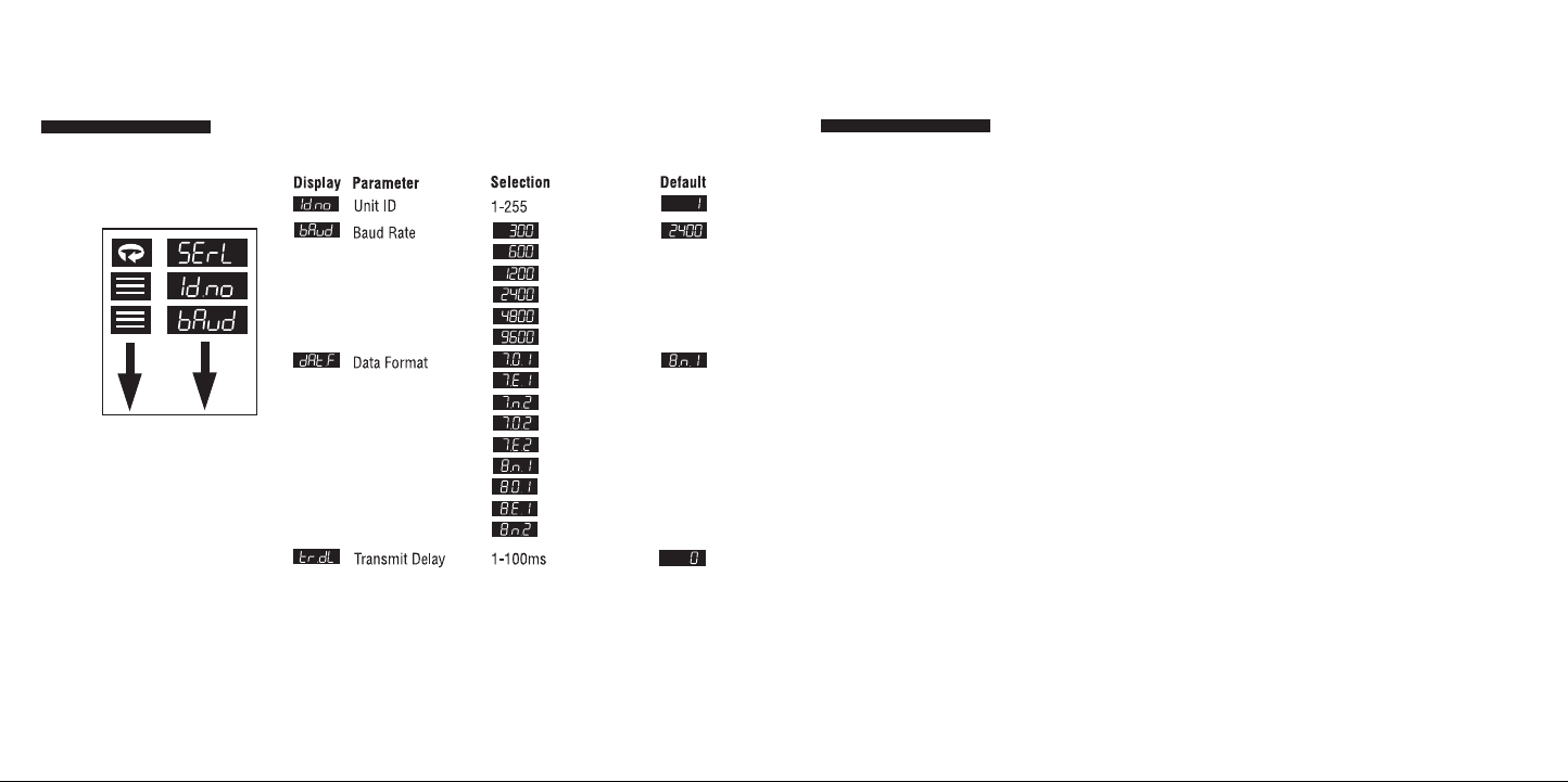
Omega+ Protocol (Standard)
Dened as 1 start bit / N# data
bits / Parity odd, even, none /
N# stop bits
Digital
Communications
Option
Message Formats
All Omega+ messages adhere to the general format of:
[START CHAR][ID][ZONE][TYPE][PARAM][ERROR]
[DATA][CHKSUM][END CHAR]
START CHAR
This is a single character which designates the start of the
message. For a Request message, this character is the ASCII
‘$’ and for a Response message, this character is the ASCII ‘%’.
ID
This is a two-character ID identifying the receiving controller.
Controller IDs go from 1-255 inclusively and all slaves in the
network must have unique IDs. The ID number of ‘00’, when
used in a request, designates a broadcast message that is
used to address all controllers in the network. See the section
Request Message for an explanation of the broadcast message.
In order to represent 255 with just two ASCII characters,
a number system known as the Message Code Numbering
System is used. In this system, the most significant digit is
represented with the numbers 0-9 and the letters A-Z and the
least significant digit is represented with the numbers 0-9.
Page 11

20
Digital
Communications
Option
The numbers 0-9 have the same values as their decimal
counterparts and the letters A-Z have the values of 100 - 350
inclusively in increments of 10.
Digital
Communications
Option
Type
This is a single character identifying the type of message.
The following table lists the type characters for all messages.
Example:
Message Code Value = Decimal Value
00 0 + 0 = 00
99 90 + 9 = 99
A0 100 + 0 = 100
A2 100 + 2 = 102
B8 110 + 8 = 118
P5 250 + 5 = 255
TYPE character Message Type
R Read Request or Read
Response Returning a
Positive Result
r Read Response Returning a
Negative Result
W Write Positive Value Request
and Response
w Write Negative Value Request
and Response
A Auxiliary Command
Zone
This is a two character ID identifying the Zone number in
multi-zone capable controllers. For the CN8200, this number
must be 01.
For further information, see following sections on the
different message types.
21
Page 12

23
Digital
Communications
Option
22
PARAM
This is a two character, message specific, parameter ID. For a
Read/Write Request or Response message, this ID identifies
the controller parameter. For an Auxiliary Command Request
or Response message, this ID specifies the command.
STATUS
This is a single-character field used in all response messages,
containing a status code specifying the status of the request
message received.
DATA
This field contains the ASCII representation of the value of the
parameter. For the Auxiliary Request or Response messages,
this field either contains the ASCII representation of a numeric
value or just ASCII data. The length of this field depends on
the message type. The discussion on the specific message
types gives the exact requirements for this field.
All ASCII representations of numeric values must be done
using the characters ‘0’-‘9’, and ‘.’. Any use of other ASCII
characters, including‘ ‘ and ‘-’ will result in a bad message.
Negative numbers CANNOT be represented by preceding the
number with ‘-’ character. Instead, a special message type is
used. See subsequent sections for more information.
Digital
Communications
Option
IMPORTANT: The data field in the Read and Write Request
and Response messages must and will only contain the
characters ‘0’-’9’, and the decimal point ‘.’. All other characters are considered illegal. When the data field is listed
as Unused or Ignored in an auxiliary command, it does
not mean that the field can be skipped when sending in the
request message. Instead, this field must be padded with
any 10 alphanumeric (only letters and numbers are allowed)
ASCII characters.
Page 13

24
25
Digital
Communications
Option
Examples of valid numeric representations for a
6 character data field:
Numeric Value ASCII Representation
3 3.0000
000003
003.00
100 100.00
0100.0
000100
3.2 003.20
0003.2
Digital
Communications
Option
CHKSUM
This is a two character Message Code Numbering System,
representing the sum of all the ASCII values of all the characters (excluding the START, CHAR, the END CHAR, and the
CHKSM themselves) in the message. The sum is computed
using the following formula:
CHKSM = SUM(All Message Characters)%256
% represents the modulus operator.
END CHAR
This is a single character designating the end of the message.
For all messages, the character used is <CR>, the carriage
return.
Examples of invalid numeric representations for 6 character
data field: (B represents a blank, or a space, character)
Numeric Value Bad ASCII Representation Why?
3 BBBBB3 Leading blanks
are not allowed.
3.0BBBB Trailing blanks
are not allowed.
-3.2 -3.20000 ‘-’ is not
allowed.
Request Messages:
Request Messages are sent from the host to the slaves.
Each request will have an ID identifying the intended recipient of the request. If the ID is ‘00’ (zero), then the request
is a broadcast message. All slaves will perform the action
requested in the broadcast request. However, a response
message will not be returned. Therefore, it only makes sense
to send Write or Auxiliary Command Requests as broadcast
requests. There are three types of Request Messages: Read,
Write, and Auxiliary Commands.
Page 14

26
27
Digital
Communications
Option
The Read Request:
The Read Request is used to query parameter values and it
has the following message format:
[START CHAR][ID][ZONE][TYPE][PARAM][CHKSUM][END CHAR]
Field Description: TYPE Must contain the uppercase letter ‘R’.
Request Message Description
$Ø1Ø1RØ5C1<CR> Queries the value of the Process Variable
of Controller #1.
$Ø1Ø1RØ9C5<CR> Queries the value of the EEPROM
Setpoint 1 of Controller #1
$Ø2Ø1RØ9C6<CR> Queries the value of the EEPROM
Setpoint 1 of Controller #2.
END CHAR
CHKSUM
PARAM
TYPE
ZONE
ID
START CHAR
Examples of the responses to these requests are given
in later sections on Response Messages.
Digital
Communications
Option
The Write Request:
The Write Request is used to modify parameter values and
it has the following message format: [START CHAR][ID][ZONE]
[TYPE][PARAM][DATA][CHKSUM][END CHAR]
Field Description: TYPE This field must contain one of the following
two characters.
W– Value in DATA is a positive value.
w– Value in DATA is a negative value.
DATA A six-character ASCII representation of a
Request Message Description
$Ø1Ø1WØ91Ø.123G7<CR> Change both the RAM and EEPROM
copies of Setpoint #1 in controller #1
to the value of 10.123
$Ø1Ø1w1Ø1Ø.123J1<CR> Change only the RAM copy of
setpoint #1 in controller #1 to
the value of -10.123 (notice the
lowercase ‘w’).
END CHAR
CHKSUM
DATA
PARAM
TYPE
ZONE
ID
START CHAR
numeric value.
Page 15

28
29
Digital
Communications
Option
The Auxiliary Command Request:
The Auxiliary Command Request is used to issue commands
to the controllers and it has the following message format:
Field Description: TYPE This field must contain the uppercase
letter ‘A’
DATA A ten-character ASCII representation of a
numeric value or 10 alphanumeric ASCII
characters.
Request Message Description
$Ø1Ø1AØ1XXXXXXXXXXL2<CR> Tell controller #1 to load
all parameters with their
defaults. The 10 X’s are
padding characters.
$Ш2Ш1AШ2ШШШ1.ШШШШШ69<CR> Tell controller #2 to
perform a low RTD
calibration.
END CHAR
CHKSUM
DATA
PARAM
TYPE
ZONE
ID
START CHAR
Digital
Communications
Option
Response Messages:
Response Messages are replies to the requests sent from the
host. For each request received, the slave will reply back with
a response.
For all requests, the Omega+ Protocol specifies a maximum
response time of 100 milliseconds. If a response is not
received after 100 milliseconds, that request can be
considered lost.
There are three types of Response Messages: Read, Write,
and Auxiliary Commands.
Page 16

30
31
Digital
Communications
Option
The Read Response:
The Read Response will be sent in response to a Read
Request. Some examples:
Request Message Description
%Ø1Ø1RØ5Ø21.123K8<CR> The value of the Process
Variable is 21.123 Degrees C.
%Ø2Ø1R1Ø1G7<CR> A serial transmission has
occurred: Framing Error
%Ø1Ø1rØ9Ø21.ØØØN8<CR> The value of the EEPROM
setpoint #1 is -21 Degrees C
(notice the lowercase ‘r’).
END CHAR
CHKSUM
DATA
STATUS
PARAM
TYPE
ZONE
ID
START CHAR
Digital
Communications
Option
The Write Response:
The Write Response will be sent in response to a Write
Request. Some examples:
Request Message Description
%Ø1Ø1WØ93I1<CR> A serial transmission error
has occurred: Parity error.
Write failed.
%Ø1Ø1w1ØØK2<CR> RAM copy of setpoint #1
modified successfully.
END CHAR
CHKSUM
STATUS
PARAM
TYPE
ZONE
ID
START CHAR
Page 17

32
33
Digital
Communications
Option
The Auxiliary Command Response:
The Auxiliary Command Response will be sent in response to
an Auxiliary Command Request.
Some examples are:
Request Message Description
%Ø1Ø1AØ1ØXXXXXXXXXXØ4<CR> Default load all para-
meters has started.
%Ш2Ш1AШ2ШШ.ШШШШШШШШB6<CR> RTD low calibration
on controller #2 has
started.
END CHAR
CHKSUM
DATA
STATUS
PARAM
TYPE
ZONE
ID
START CHAR
Digital
Communications
Option
Table 1. Communications Parameter List (Omega+ Protocol)
Parameter Parameter
Number Description Number Description
1 Controller Type 19 Manual Control
2 Software Version 2 Percentage
3 Communications 2Ø Output 1 Deadband
Version 21 Output 1 Hysteresis
4 Status Byte 22 Output 1 Proportional
5 Process Value Band
6 Operating Mode 23 Output 2 Proportional
7 Access Level Band
8 Contact/Digital 3Ø Rate/Derivative Action
Input State 32 Reset/Integral Action
9 Setpoint - RAM, 34 Manual Reset/
EEPROM Internal Action
1Ø Setpoint - RAM 37 Output 2 Deadband
Only 38 Output 2 Hysteresis
11 Second Setpoint - 39 Autotune Damping
RAM, EEPROM 4Ø Recipe Option
12 Second Setpoint - 41 Single Setpoint Ramp
RAM Only Time
13 Remote Analog 42 Ramp Time 1
Setpoint 43 Ramp Time 2
14 Recipe Setpoint 44 Ramp Time 3
16 Output 1 Percentage 45 Ramp Time 4
17 Output 2 Percentage 46 Ramp Time 5
18 Manual Control 47 Ramp Time 6
1 Percentage 48 Ramp Time 7
Page 18

34
35
Digital
Communications
Option
Table 1. Continued
Parameter Parameter
Number Description Number Description
49 Ramp Time 8 73 Soak Time 8
5Ø Ramp Event 1 74 Soak Event 1
51 Ramp Event 2 75 Soak Event 2
52 Ramp Event 3 76 Soak Event 3
53 Ramp Event 4 77 Soak Event 4
54 Ramp Event 5 78 Soak Event 5
55 Ramp Event 6 79 Soak Event 6
56 Ramp Event 7 8Ø Soak Event 7
57 Ramp Event 8 81 Soak Event 8
58 Soak Level 1 82 Recycle Number
59 Soak Level 2 83 Holdback Band
6Ø Soak Level 3 84 Termination State
61 Soak Level 4 85 Power Resume
62 Soak Level 5 86 Input Bias
63 Soak Level 6 87 Input Low Scale
64 Soak Level 7 88 Input High Scale
65 Soak Level 8 89 Lower Setpoint Limit
66 Soak Time 1 9Ø Upper Setpoint Limit
67 Soak Time 2 91 Input Filter
68 Soak Time 3 92 Input Type
69 Soak Time 4 94 Output 1 Type
7Ø Soak Time 5 95 Output 1 Action
71 Soak Time 6 96 Output 1 Alarm
72 Soak Time 7 Action
Digital
Communications
Option
Table 1. Continued
Parameter
Number Description
97 Output 1 Alarm Operation
98 Output 1 Alarm Delay
99 Output 1 Alarm Inhibit
AØ Output 1 Process
Alarm Setpoint
A1 Output 1 Deviation
Alarm Setpoint
A2 Output 1 Cycle Time
A3 Output 1 Low Limit
A4 Output 1 High Limit
A5 Output 2 Type
A6 Output 2 Action
A7 Output 2 Alarm
Action N/A
A8 Output 2 Alarm Operation
A9 Output 2 Alarm
Delay N/A
BØ Output 2 Alarm Inhibit
B1 Output 2 Process
Alarm Setpoint
B2 Output 2 Deviation
Alarm Setpoint
B3 Output 2 Cycle Time
B4 Output 2 Low Limit
B5 Output 2 High Limit
Parameter
Number Description
B6 TC/RTD Decimal Position
B7 Linear Decimal Position
B8 Display Filter
B9 Display Units
C1 Display Blanking
C2 Alarm 1 Action
C3 Alarm 1 Operation
C4 Alarm 1 Delay
C5 Alarm 1 Inhibit
C6 Alarm 1 Process Setpoint
C7 Alarm 1 Deviation Setpoint
C8 Alarm 2 Action
C9 Alarm 2 Operation
DØ Alarm 2 Delay
D1 Alarm 2 Inhibit
D2 Alarm 2 Process Setpoint
D3 Alarm 2 Deviation Setpoint
D4 Communication Protocol
D5 Communication ID
D6 Communication Baud Rate
D7 Communication Data Format
D8 Communication
Transmit Delay
E1 Output 1 Failsafe %
E2 Output 2 Failsafe %
Page 19

36
37
Digital
Communications
Option
Table 1. Continued
Parameter
Number Description
E3 Loop Break Time
E4 Highest Reading
E5 Lowest Reading
E8 Option Selection N/A
E9 TC Zero Calibration
FØ TC Span Calibration
F1 RTD Zero Calibration
F2 RTD Span Calibration
F3 Low-Voltage Zero
Calibration
F4 Low-Voltage Span
Calibration
F5 High-Voltage Zero
Calibration
F6 High-Voltage Span
Calibration
F7 Current Zero Calibration
F8 Current Span Calibration
G1 Auxiliary Output Variable
G2 Auxiliary Output
Scale Low
G3 Auxiliary Output
Scale High
G5 RAS Scale Low
G6 RAS Scale High
Parameter
Number Description
G7 Contact/Digital
Switch Function
H2 Autotune State
H3
H5 Current Recipe
Segment
H6 Active Setpoint
H7 Resume Exhaustion
Flag
F4 Low-Voltage Span
H8 LED Status Indicator
H9 RTD (with decimal
support) Zero Calibration
IØ RTD (with decimal
support) Span Calibration
Recipe
State
Digital
Communications
Option
Auxiliary Commands:
Command: Load Parameter Defaults
Parameter #: 01
Description Restore all menu parameters to their
default values.
Request Data Field: Ignored.
Response Data Field: Ignored.
Command: Perform Process Low Calibration
Parameter #: 02
Description: Performs a Low Calibration. The
data field in the request message
specifies the process. Make sure the
prerequisite for the calibration is
satisfied before issuing a calibration
command. For instance, the RTD
calibration command must only be
used when the input sensor type is
chosen as RTD or RTD w/ Decimal.
Page 20

38
39
Digital
Communications
Option
Request Data Fields: A 10 character ASCII representation
of a numeric value specifying what
to calibrate.
0 - Thermocouple
1 - RTD, Resistive Thermal Device
2 - Linear
3 - RAS, Remote Analog Setpoint
Response Data Field: Ignored.
Command: Perform Process High Calibration
Parameter #: 03
Description: Performs a High Calibration. The data
field in the request message specifies
the process. Make sure the prerequi site for the calibration is satisfied
before issuing a calibration command
For instance, the RTD calibration
command must only be used when the
input sensor type is chosen as RTD or
RTD w/ Decimal.
Request Data Field: A 10 character ASCII representation
of a numeric value specifying what
to calibrate.
Digital
Communications
Option
0 - Thermocouple
1 - RTD, Resistive Thermal Device
2 - Linear
3 - RAS, Remote Analog Setpoint
Command: Retrieve Display
Parameter #: 05
Description: Retrieves the string currently dis-
played on the slave’s display. The data
field in the request message specifies
which display and the data field in the
response message contains the string.
Request Data Field: A 10 character ASCII representation
of a numeric value specifying which
display to retrieve data from.
0 - Lower Display
1 - Upper Display
Response Data Field: The ASCII string.
Command: Clear Latched Alarms
Parameter #: 10
Description: Clear all latched alarms.
Request Data Field: Ignored.
Response Data Field: Ignored.
Page 21

40
Digital
Communications
Option
Table 2. Communications Error Codes Returned.
Notes
Code Description
0 No error.
1 Framing error.
2 Hardware error.
3 Parity error.
4 Bad character in the TYPE field.
5 Bad message. Message cannot be understood.
6 Bad checksum. The checksum received did not
match the checksum of the message.
7 Bad zone ID.
8 Bad auxiliary command ID. The auxiliary command
is not supported in this controller.
9 Bad parameter ID. The parameter is not supported
in this controller.
A Bad data. Bad representation in the data field or
data is out of range.
B Attempt to write to a read only parameter.
C Cannot write to a parameter because it’s in use.
41
Page 22

Notes
42
OMEGA ENGINEERING, INC. warrants this unit to be free of defec ts in materials and workmanship for a period of 25 months
WARRANTY/ DISCLAIMER
from date of purchase. OMEGA Warranty adds an additional one (1) month grace period to the normal two (2) year product
warranty to cover handling and shipping time. This ensures that OMEGA’s customers receive maximum coverage on each prod-
uct.
If the unit malfunctions, it must be returned to the factory for evaluation. OMEGA’s Customer Service Department will issue an
Authorized Return (AR) number immediately upon phone or written request. Upon examination by OMEGA, if the unit is found to be
defective it will be repaired or replaced at no charge. OMEGA’s WARRANTY does not apply to defects resulting from any action of
the purchaser, including but not limited to mishandling, improper interfacing, operation outside of design limits, improper repair, or
unauthorized modification. This WARRANTY is VOID if the unit shows evidence of having been tampered with or shows evidence of
having been damaged as a result of excessive corrosion; or current, heat, moisture or vibration; improper specification; misapplication;
misuse or other operating conditions outside of OMEGA’s control. Components which wear are not warranted, including but not limited
to contact points, fuses, and triacs.
OMEGA is pleased to offer suggestions on the use of its various products. However, OMEGA neither assumes
responsibility for any omissions or errors nor assumes liability for any damages that result from the use of
its products in accordance with information provided by OMEGA, either verbal or written. OMEGA warrants
only that the parts manufactured by it will be as specified and free of defects. OMEGA MAKES NO OTHER
WARRANTIES OR REPRESENTATIONS OF ANY KIND WHATSOEVER, EXPRESS OR IMPLIED, EXCEPT THAT OF
TITLE, AND ALL IMPLIED WAR RANTIES INCLUDING ANY WARRANTY OF MERCHANTABILITY AND FITNESS
FOR A PARTICU LAR PUR POS E ARE HEREBY DISCLA IMED. LIMITAT ION OF LIABIL ITY: The reme dies of
purchaser set forth herein are exclusive, and the total liability of OMEGA with respect to this order, whether
based on contract , warra nty, neglig ence, indemnifica tion, strict liabilit y or otherw ise, sha ll not exceed
the purchase price of the component upon which liability is based. In no event shall OMEGA be liable for
consequential, incidental or special damages.
CONDITIONS: Equipment sold by OMEGA is not intended to be used, nor shall it be used: (1) as a “Basic Component” under 10
CFR 21 (NRC), used in or with any nuclear installation or activity; or (2) in medical applications or used on humans. Should any
Product(s) be used in or w ith any nuclear installation or activity, medical application, used on humans, or misused in any way,
OMEGA assumes no responsibility as set for th in our basic WARRANTY/ DISCLAIMER language, and, additionally, purchaser
will indemnify OMEGA and hold OMEGA harmless from any liability or damage wha tsoever arising out of the use of the
Product(s) in such a manner.
Direct all warranty and repair requests/inquir ies to the OMEGA Customer Ser vice Department. BEFORE RETURNING ANY
PRODUCT(S) TO OMEGA, PURCHASER MUST OBTAIN AN AUTHORIZED RETURN (AR) NUMBER FROM OMEGA’S CUSTOMER
SERVICE DEPARTMENT (IN ORDER TO AVOID PROCESSING DELAYS). The assigned AR number should then be marked on the
outside of the return package and on any correspondence.
The purchaser is responsible for shipping charges, freight, insurance and proper packaging to prevent breakage in transit.
FOR WARRANTY RETURNS, please have the
following information available BEFORE contac ting
OMEGA:
1. Purchase Order number under which the
product was PURCHASED,
2. Model and serial number of the product under
warrant y, and
3. Repair instructions and/or specific problems
relative to the product.
OMEGA’s policy is to make running changes, not model changes, whenever an improvement is possible. This affords our customers the
latest in technology and engineering.
OMEGA is a registered trademark of OMEGA ENGINEERING, INC.
© Copyright 2004 OMEGA ENGINEERING, INC. All rights reserved. This document may not be copied, photocopied, reproduced, translated, or reduced
to any electronic medium or machine-readable form, in whole or in part, without the prior written consent of OMEGA ENGINEERING, INC.
RETURN REQUESTS/ INQUIRIES
FOR NON-WARRANTY REPAIRS,
for current repair charges. Have the following
information available BEFORE contacting OMEGA:
1. Purchase Order number to cover the COST
of the repair,
2. Model and serial number of the product, and
3. Repair instructions and/or specific problems
relative to the product.
consult OMEGA
Page 23

Where Do I Find Everything I Need for
Process Measurement and Control?
OMEGA…Of Course!
TEMPERATURE
• Thermocouple, RTD & Thermistor
Probes, Connectors, Panels & Assemblies
• Wire: Thermocouple, RTD & Thermistor
• Calibrators & Ice Point References
• Recorders, Controllers & Process Monitors
• Infrared Pyrometers
PRESSURE, STRAIN
AND FORCE
•
Transducers & Strain Gages
•
Load Cells & Pressure Gages
•
Displacement Transducers
•
Instrumentation & Accessories
FLOW/LEVEL
•
Rotameters, Gas Mass Flowmeters
& Flow Computers
•
Air Velocity Indicators
•
Turbine/Paddlewheel Systems
•
Totalizers & Batch Controllers
pH/CONDUCTIVITY
•
pH Electrodes, Testers & Accessories
•
Benchtop/Laboratory Meters
•
Controllers, Calibrators, Simulators
& Pumps
•
Industrial pH & Conductivity Equipment
DATA ACQUISITION
•
Data Acquisition &
Engineering Software
•
Communications-Based
Acquisition Systems
•
Plug-in Cards for Apple, IBM
& Compatibles
•
Datalogging Systems
•
Recorders, Printers & Plotters
HEATERS
•
Heating Cable
•
Cartridge & Strip Heaters
•
Immersion & Band Heaters
•
Flexible Heaters
•
Laboratory Heaters
ENVIRONMENTAL
MONITORING AND CONTROL
•
Metering & Control Instrumentation
•
Refractometers
•
Pumps & Tubing
•
Air, Soil & Water Monitors
•
Industrial Water & Wastewater
Treatment
•
pH, Conductivity & Dissolved
Oxygen Instruments
M3396/0699
 Loading...