

Page 1

Page 2

Page 3
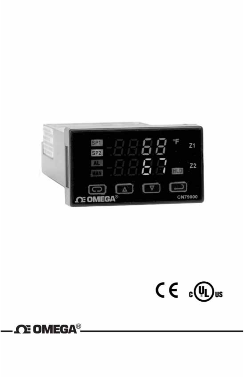
INSTRUCTIONS FOR THE CN79000
1/32 DIN DUAL ZONE MICROPROCESSOR BASED
TEMPERATURE/PROCESS CONTROL
OMEGA Engineering
One Omega Drive
Stamford, Connecticut 06907-0047
P.O. Box 4047
Telephone: 800/848-4286; 203/359-1660
Fax: 203/359-7700
Page 4

Contents
INSTALLATION . . . . . . . . . . . . . . . . . . . . . . . . . . . . . . . . . . . . . . . . . . .3
WIRING . . . . . . . . . . . . . . . . . . . . . . . . . . . . . . . . . . . . . . . . . . . . . . . . . .5
Wiring for Optional Inputs and Outputs . . . . . . . . . . . . . . . . . . . . . . . . .6
Wiring for 4 to 20mA Transmitter inputs . . . . . . . . . . . . . . . . . . . . . . . . .7
FRONT PANEL KEY FUNCTIONS . . . . . . . . . . . . . . . . . . . . . . . . . . . . .8
NOTATION CONVENTIONS FOR THE MENUS . . . . . . . . . . . . . . . . .10
THE HOME DISPLAY . . . . . . . . . . . . . . . . . . . . . . . . . . . . . . . . . . . . . .10
ALARM TYPE AND ACTION . . . . . . . . . . . . . . . . . . . . . . . . . . . . . . . .11
OPERATION OF SELF TUNE® FUNCTION . . . . . . . . . . . . . . . . . . . .12
Theory of Operation . . . . . . . . . . . . . . . . . . . . . . . . . . . . . . . . . . . . . . .12
Program Setup and Operation . . . . . . . . . . . . . . . . . . . . . . . . . . . . . . .13
OPERATION AND PROGRAMMING OF OPTIONS . . . . . . . . . . . . . .13
Option C4, Serial Communication . . . . . . . . . . . . . . . . . . . . . . . . . . . .13
FACTORY DEFAULT PROCEDURE . . . . . . . . . . . . . . . . . . . . . . . . . .14
MENU SELECTIONS . . . . . . . . . . . . . . . . . . . . . . . . . . . . . . . . . . . . . .14
PRIMARY MENU . . . . . . . . . . . . . . . . . . . . . . . . . . . . . . . . . . . . . . . . .14
SECONDARY MENU . . . . . . . . . . . . . . . . . . . . . . . . . . . . . . . . . . . . . .15
SECURE MENU . . . . . . . . . . . . . . . . . . . . . . . . . . . . . . . . . . . . . . . . . .25
SPECIFICATIONS . . . . . . . . . . . . . . . . . . . . . . . . . . . . . . . . . . . . . . . .35
DIAGNOSTIC ERROR MESSAGES . . . . . . . . . . . . . . . . . . . . . . . . . .37
DIAGNOSTIC ERROR MESSAGES . . . . . . . . . . . . . . . . . . . . . . . . . .38
DIMENSIONS . . . . . . . . . . . . . . . . . . . . . . . . . . . . . . . . . . . . . . . . . . . .40
Page 2 of 40
Page 5

CN790
MODEL IDENTIFICATION
Output
2 = Switched
Output A
2 = Switched Voltage 5
VDC
3 = Relay
5 = Current
3 = Relay
Voltage 5VDC
Options
C4 = RS485
LV = Low Voltage
Options:
C4 RS-485 Serial Communications. Allows remote computer to read
and write all control parameters.
LV 12-24 Vdc/Vac 50-400Hz power supply (control operates on low
voltage equipment).
INSTALLATION
All models are designed for mounting in an enclosed panel. Select the
position desired for the instrument on the panel. If more than one instrument is required, maintain the minimum of spacing requirements as shown
on the drawing opposite. Closer spacing will structurally weaken the panel,
and invalidate the IP66, UL type 4 rating of the panel.
Page 3 of 40
It is not necessary to remove the instrument chassis from
the housing for installation. If the instrument chassis is
removed from the housing, you must follow the ANSI/IPCA-610 standard for handling electronic assemblies to avoid
damage from Electro-Static Discharge (ESD). Failure to
properly handle the instrument may cause damage to the
instrument.
Page 6
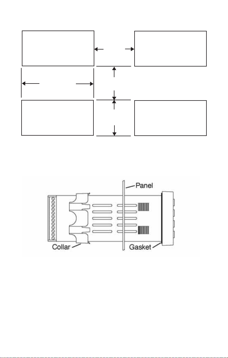
Prepare the panel by cutting and deburring the required opening(s).
25.4
(1.00)
45 + 0.6
(1.772 + 0.02)
20.5
(0.807)
22.2 + 0.3
(0.874 + 0.012)
From the front of the panel, slide the housing through the cutout. The housing gasket should be flat against the housing flange before installing.
From the rear of the panel slide the mounting collar over the housing. Hold
the housing with one hand and using the other hand, push the collar evenly against the panel until the spring loops are slightly compressed. The
ratchets will hold the mounting collar and housing in place. To remove,
gently lift the ratchets and slide a piece of heavy paper or mylar sheet
under each ratchet (a business card works well). Slide the collar off of the
housing.
Page 4 of 40
Page 7

WIRING
WARNING: The inputs of the instrument are not isolated from each other. The input sources must be isolated from each other. Thermocouples MUST be of the
isolated junction type. Process inputs may not share a
common external ground.
FAILURE TO OBSERVE THIS WARNING MAY CAUSE
DANGEROUS OR LETHAL VOLTAGES TO BE PRESENT IN THE INSTRUMENT WHICH MAY CAUSE SERIOUS INJURY OR DEATH.
DO NOT RUN SIGNAL (CLASS 2) WIRING IN THE
SAME CONDUIT OR CHASE AS THE POWER WIRING.
ERRATIC OPERATION OR DAMAGE TO THE INSTRUMENT CIRCUITRY WILL RESULT.
Maintain separation between wiring of sensor auxiliary
in or out, and other wiring. See the “Secure Menu” for
input selection.
For thermocouple input always use extension leads of the same type
designated for your thermocouple.
For supply connections use No. 18 AWG wires rated for at least 75°C.
Use copper conductors only. All line voltage outputs circuits must
have a common disconnect and be connected to the same pole of
disconnect.
Input wiring for thermocouple is rated CLASS 2.
Page 5 of 40
Page 8
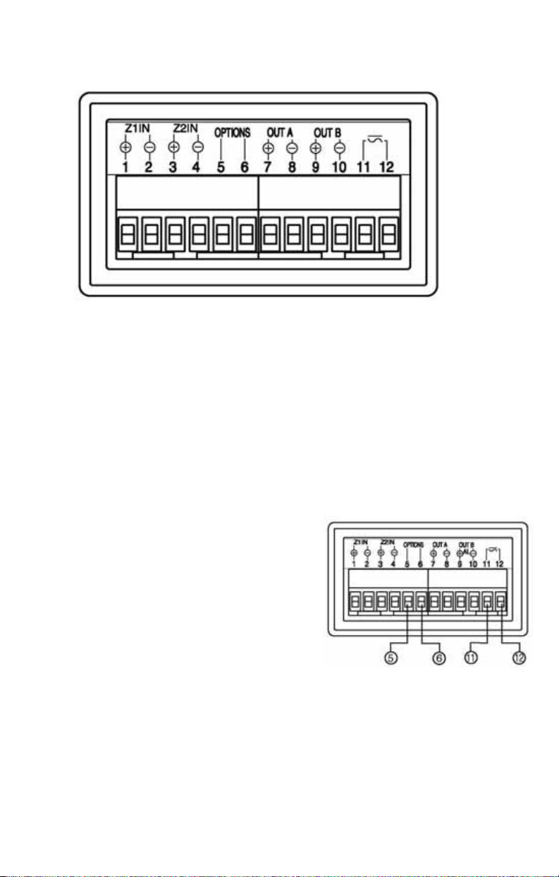
Control wiring is as shown
Zone 1 Zone 2
Input Input Output A* Output B* Power
*Output A is assigned to Zone 1 Input and Output B is assigned to Zone 2 Input. If necessary, the input/output relationships may be revised. See
SP1o in Secure Menu.
The wiring terminals for the CN79000 are compression type. To open the
wiring terminal, turn the screw for the terminal counterclockwise. Slide the
wire into the terminal space. While holding the wire in place, turn the screw
clockwise to tighten. Maximum torque is 0.424 N m (3.75 in. lb.). Do not
overtighten. The wire should be held snugly in place.
Wiring for Optional Inputs and Outputs
Wire power and outputs as shown. Wiring for options is shown
below. All wiring shown below is Class 2. Shielded twisted pair is
required for Option C4.
Option C4: Terminal 5 is line A (-)
Terminal 6 is line B (+)
Last control in chain must have 120 ohm ±1%
resistor across 5 and 6.
Option LV: Connect 12 to 24 Volta ac or
dc power to terminals 11 and
12. No polarity.
Note: Industry standard designation for RS-485 lines is A and B. Some equipment manufacturers use a non-standard designation of plus and minus. The association of A to minus
and B to plus is based on a sample of devices marked as plus and minus and is not intended to represent ALL such labeled devices. Final responsibility for correct identification of
leads and terminals rests with the user/installer and the manufacturer of the other device(s)
installed in the system.
Page 6 of 40
Page 9
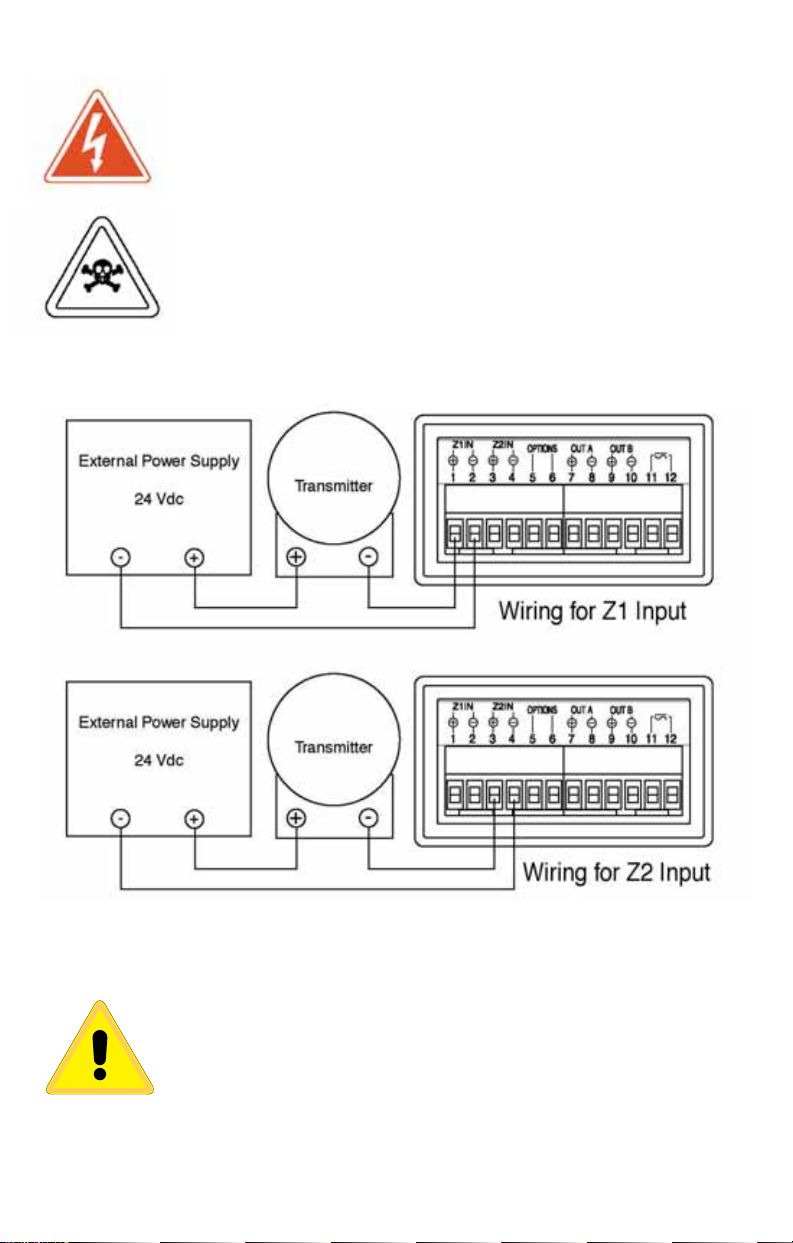
Wiring for 4 to 20mA Transmitter inputs
WARNING: The inputs of the instrument are not isolated from each other. The input sources must be isolated from each other. Process inputs may not share a
common external ground.
FAILURE TO OBSERVE THIS WARNING MAY CAUSE
DANGEROUS OR LETHAL VOLTAGES TO BE PRESENT IN THE INSTRUMENT WHICH MAY CAUSE SERIOUS INJURY OR DEATH.
Wire power and outputs as shown above. Two-wire transmitters wire as
shown below.
For three or four wire transmitters follow the wiring instructions provided
with your transmitter.
DO NOT WIRE THE 24 VOLT POWER SUPPLY
ACROSS THE INPUT OF THE CONTROL. DAMAGE TO
THE INSTRUMENT INPUT CIRCUITRY WILL RESULT.
Page 7 of 40
Page 10
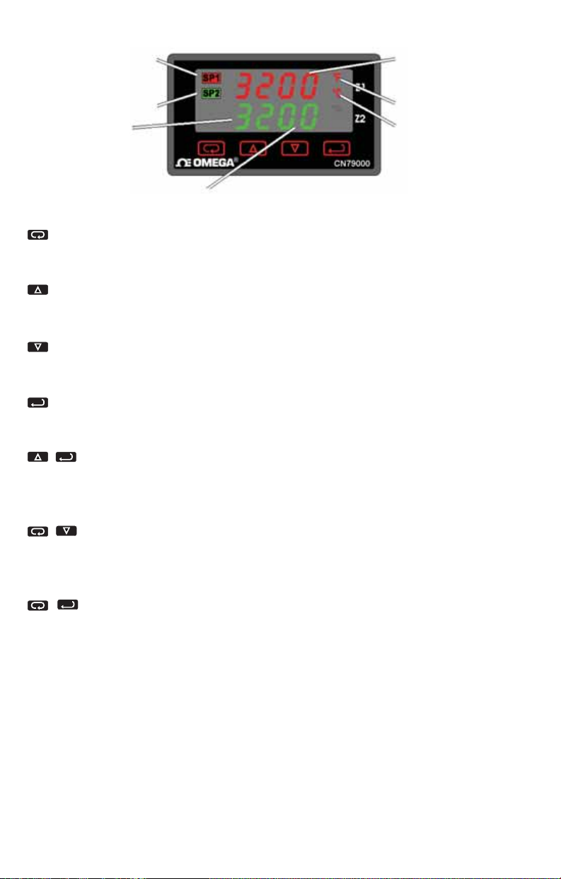
FRONT PANEL KEY FUNCTIONS
Set Point 1 Lamp
Set Point 2 Lamp
SP2 Process
Display
The decimal point flashes when Self-Tune is operating.
INDEX: Pressing the INDEX key advances the display to the next
menu item. May also be used in conjunction with other keys as noted
below.
UP ARROW: Increments a value, changes a menu item, or selects the
item to ON. The maximum value obtainable is 9999 regardless of decimal
point placement.
DOWN ARROW: Decrements a value, changes a menu item, or
selects the item to OFF. The minimum value obtainable is -1999 regardless of decimal point placement.
ENTER: Pressing ENTER stores the value or the item changed. If not
pressed, the previously stored value or item will be retained. The display
will flash once when ENTER is pressed.
UP ARROW & ENTER: Pressing these keys simultaneously
brings up the secondary menu starting at the alarm, tune, or cycle item
(depending on programming). Pressing these keys for 5 seconds will bring
up the secure menu.
INDEX & DOWN ARROW: Pressing these keys simultaneously
will allow backing up one menu item, or if at the first menu item they will
cause the display to return to the primary menu. If an alarm condition has
occurred, these keys may be used to reset the alarm.
INDEX & ENTER: Pressing these keys simultaneously and holding them for 5 seconds allows recovery from the various error messages.
The following menu items will be reset:
SP1 Process
Display
Scale Lamp ˚F
Scale Lamp ˚C
OPEn InP: Input error message bAd InP: Input error message
CHEC CAL: Check calibration error
Correct the problems associated with the above conditions before using
these reset keys. More than one error could be present. Caution is advised
since several items are reset at one time.
While in the Primary or Secondary Menu, if no key is pressed for a period of 30 seconds, the display will return to the HOME position displaying
Page 8 of 40
Page 11
the temperature value. While in the Secure Menu, if no key is pressed for
a period of 60 seconds, the display will return to the HOME position displaying the temperature value. Outputs are disabled (turn off) when the
Secure Menu is active.
NOTE: To move to the Primary Menu quickly from any other menu, press
the UP ARROW & ENTER keys followed by pressing the INDEX & DOWN
ARROW keys.
SECURITY LEVEL SELECTION
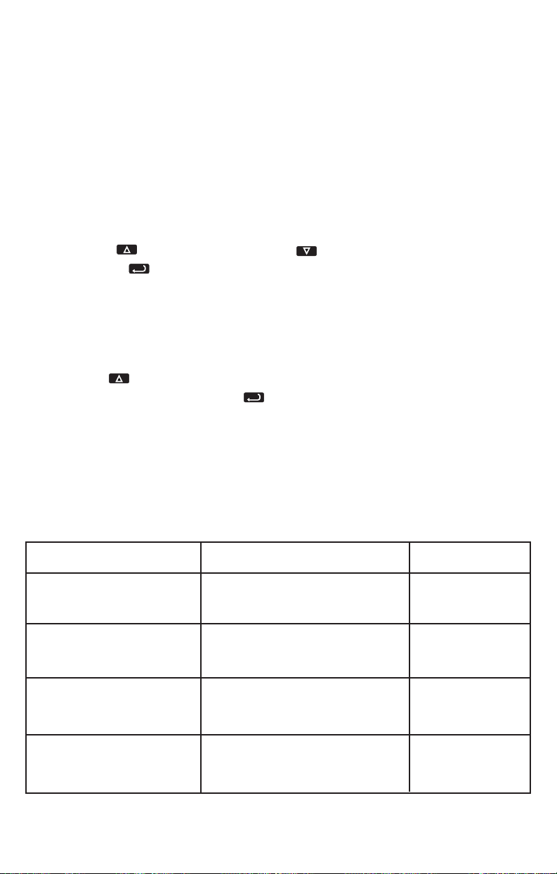
Four levels of security are provided. The display shows the current
security level. To change security levels change the password value
using the UP ARROW and DOWN ARROW keys and
pressing the ENTER key. Refer to the password table (following) for the correct value to enter for the security level desired. The
SEC1 or SEC2 menu items security level may be viewed or changed
at any time regardless of the present security level.
To set the access level to, for example, 2, at the SEC1 menu item
press the UP ARROW key until the upper display shows the
password,
1101. Press the ENTER key. The display will blink,
and return with the level value, 2, in the upper display.
The password values shown in the table cannot be altered, so retain
a copy of these pages for future reference. The is the only reference
made to password values in this instruction book.
PASSWORD TABLE
Menu Security Level
Status
Primary Locked
Secondary Locked
Secure Locked
Primary Unlocked
Secondary Locked
Secure Locked
Primary Unlocked
Secondary Unlocked
Secure Locked
Primary Unlocked
Secondary Unlocked
Secure Unlocked
Page 9 of 40
Displayed Value
When Viewed
1
2
3
4
Password Value
To Enter
1110
1101
1011
111
Page 12

NOTATION CONVENTIONS FOR THE MENUS
Because of the number of features available in this control, information is
included that may not apply to your specific control. All usable features are
included in this book, but may not be used in your process. To increase
clarity the following conventions are used:
1. Certain features, Menu Items, and functions shown in this book may or
may not appear on your control, depending on other Menu Item selections.
At various places in the Menus there are notes identifying Menu Items that
“control” or “direct” other menu items. If you are looking for a particular
menu item and can’t find it, check the menu item that is its “control” for
proper setting.
2. The “#” symbol is used in two ways. It is used inside a group of characters to indicate which set point function (SP1 or SP2) is being affected. It
is also used before a group of characters of a menu item to indicate that
there may be more than one selection or value for that menu item.
3. Features that apply only to Options will be printed in Italics.
THE HOME DISPLAY
The home display is the normal display while the control is operating. If no
errors or functions are active, the HOME display ill indicate the Process
Variable for Set Point 1 on the top display and the Process variable for Set
Point 2 on the bottom.
THE MENU EDIT FUNCTION
The Menu Edit function (
Edit) allows quick access to operational and set
up menu items for either or both of the zones. The Edit menu item appears
at the top of the Secondary Menu and allows selection of the set point
parameters. Setting
PEA2), Valley (UAL1 and UAL2), Local/Remote (L rE), and address
Addr) menu items.
(
Setting
Edit for either 1 or 2 allows access to the Secondary and Secure
Edit to 0 allows access to only the Peak (PEA1 and
Menus for the zone selected.
Setting
Edit for 3 allows access to both the Secondary and Secure
Menus for both Zone 1 and Zone 2. Each menu presents the menu items
for Zone 1 first, followed by the menu items for Zone 2, followed by any
common menu items that may be present.
Page 10 of 40
Page 13

Menu items that are dedicated to either Zone 1 or Zone 2 will have either
a 1 or 2 in them for identification.
Edit is set to any value other than 0, the setting will be retained for a
If
period of five minutes to allow handy, repeated access to that zone’s
menus. After five minutes of keypad inactivity, the
0, giving an added layer of security to prevent inadvertent changes to
to
Edit setting will revert
the instrument.
PROGRAMMING SET POINTS FOR ALARM FUNCTIONS
CAUTION: In any critical application where failure
could cause expensive product loss or endanger per-
sonal safety, a redundant limit controller is required.
The CN74000 Series allows Zone 1 and / or Zone 2 to operate as limit or
alarm type outputs. This function is available on both outputs. To enable a
zone output to act as an alarm or limit,
Zone 2) should be set for
0n0F.
0ut 1 (for Zone 1) or 0ut 2 (for
When
0ut 1 and / or 0ut 2 are set to 0n0F, then the alarm function menu
items will appear in the Secure Menu for the selected zone(s).
When Set Point Power interrupt (
Reset (
S#rE) is programmed for HoLd, the alar m will automatically reset
S#Pi) is programmed 0n and Set Point
after a power failure and on subsequent power restoration if no alarm condition is present.
If Set Point Inhibit (
power up until the process value passes through the alarm set point once. Alarm
inhibit can be restored as if a power up took place by pressing both the INDEX
and ENTER keys for 5 seconds.
S#iH) is selected 0n, an alarm condition is suspended upon
Warning: If inhibit is on and a power failure occurs during a
high alarm, on restoration of power inhibit will suppress the
alarm. Do not use the Set Point Inhibit feature if a hazard
may be created by this action. Be sure to test all combina-
tions of high and low set point inhibit actions before placing
control into operation.
Page 11 of 40
Page 14

Set Point 2 Tracking
Some applications will call for Set Point 2 to follow or ‘track’ the setting for
Set Point 1. This can be done by changing the
Menu (
Edit set for 2 or 3). For a tracking SP2, set 52t to dE.
52t setting in the Secure
The Factory Default setting for
pendent of
When setting
52t = dE), set the difference in value from the Set Point 1 (SP1) desired.
(
SP1.
SP2 value when Set Point 2 is programmed as a deviation
For example if Set Point 2 required to be 5 degrees below the
SP2 to -5. If Set Point 2 is required 20 degrees above the SP1, then
set
5P2 to 20. If SP1 is charged, the SP2 setting will continue to hold the
set
52t is Ab5, making S 2 completely inde-
SP1, then
same relationship as originally set.
®
OPERATION OF SELF TUNE
FUNCTION
Self Tune® allows automatic selection of the necessary parameters to
achieve best control operation from your CN74000 Series control. If you
are using the control output as a simple on-off function (e.g.
0n0F), none of the following will apply.
0ut 1 set for
Theory of Operation
The Self Tune function calculates the
under the
P1d2tunE selection, the Fbd1 and Frt1 parameters, and the Fbd2
the
P1d1tunE selection, Pb2, rES2, and rtE2 parameters under
Pb1, rES1, and rtE1 parameters
and Frt2 parameters, as shown in the Secondary Menu. These values
are determined by measuring the response of the process connected to
the control. When Self Tune is started, the control temporarily acts as an
on-off control. While in this mode the control measures the overshoot and
undershoot of the process, and the period of the process (the time from
peak value to the next peak value). These measurements are collected
over a period that lasts three periods of overshoot and undershoot. The
data collected over this time is then compared and calculated into final PID
and Fuzzy Logic values. The effect of Fuzzy Logic on the process is still
controlled by the
0, the Fbd1, Frt1, Fbd2, and Frt2 will be calculated, but will have no
Fi1 and Fi 2 (fuzzy intensity) settings. If Fi1 or Fi 2 is
effect.
The calculations for Zone 1 and Zone 2 are completely independent. Each
zone has separate Self Tune and Fuzzy Logic parameters.
Page 12 of 40
Page 15

The calculations for the PID values are the same as used in the standard
Ziegler - Nichols equations that have been recognized as standard for
decades.
The only modification to the application of the Ziegler - Nichols equations
is controlled by the
trol the amount or rate (derivative) that is applied. A
3 (factory default) or less allows for less damping. A dFC1 or dFC2
of
dFC1 and dFC2 menu items. These menu items con-
dFC1 or dFC2 setting
setting of 4 allows for critical damping as set forth in Ziegler - Nichols. A
dFC1 or dFC2 setting of 5 or more allows over damping of the process.
Program Setup and Operation
In the secondary menu
to make sure that
Lrn1/Lrn2 and set to YES. The control will begin the Self Tune function.
tun1 or tun2 to SELF. Skip Lrn1/Lrn2 and check
dFC1/dFC2 is (are) set to the desired value. Back up to
While the Self Tune function is active, the right hand decimal point on the
lower display will blink. When Self Tune is complete, the blinking will stop.
OPERATION AND PROGRAMMING OF OPTIONS
Option C4, Serial Communication.
The serial communications option allows the control to be written to and
read from a remote computer or other similar digital device.
Communication is allowed through RS-485 (Option C4) port.
See Wiring for Optional Inputs and Outputs for information on wiring the
communication lines. Wiring for the RS-485 is run from control to control in
a daisy chain fashion with a termination resistor (120 ohms) across the
transmit and receive terminals of the last control in the chain.
Select the control address and communication baud rate with the
Addr
and bAUd menu items in the Secure Menu. The address for Zone 1 will be
the address selected. The address for Zone 2 will be the address selected
for Zone 1 plus one. For example, if
will be addressed through address
addressed through address
Page 13 of 40
1F.
Addr is set to 1E, Zone 1 parameters
1E and Zone 2 parameters will be
Page 16

THE BAUD RATE AND ADDRESS MENU ITEMS WILL TAKE EFFECT
ON THE NEXT POWER UP OF THE CONTROL. BE SURE TO POWER
CYCLE THE CONTROL BEFORE USING THE NEW BAUD RATE AND
ADDRESS.
In operation, you have the option of preventing a write command from the
host computer. To prevent the host from writing to the control change the
L0rE menu item in the Secondary Menu to L0C. To allow the host to write
commands to the control set
to change the
L0rE state, but is not automatic.).
L0rE to rE. (The host does have the ability
If your system depends on constant reading or writing to and from the host,
you may wish to set the NO Activity Timer (
of the control. When the
other than
0FF, the control will expect to be addressed on a regular basis.
L0rE is set to rE and the nAt is set to any value
nAt) to monitor the addressing
If the control is not addressed in the time set by the value of nAt, then the
control will display the error message
L0rE to L0C.
set
CHEC L0rE. To clear the message
FACTORY DEFAULT PROCEDURE
If for any reason you wish to restore the factory settings use the following
procedure.
1. Turn off power to control.
2. Turn on power to control.
3. While control is performing
SELF tESt, press and hold the
INDEX and ENTER keys.
4. The control will display the ROM ID code. Press INDEX.
5. The control will display
FACt dFLt. If you wish to just restore
factory settings, Press ENTER and DOWN ARROW at
the same time. The control will be reset to the original factory
settings.
6. Press INDEX to display
0Pt. If your control is equipped with
an option, press the UP ARROW to display the option number.
If the number is flashing, press ENTER. An enabled option
does not flash.
7. Press INDEX to display
YES Changes are accepted and control re-boots.
no Changes are discarded and control re-boots.
ACPt. Select YES or no.
8. Press ENTER.
The control will re-initialize with Factory Default settings.
Page 14 of 40
Page 17

MENU SELECTIONS
PRIMARY MENU
Press INDEX to advance to the next menu item. Press UP ARROW or
DOWN ARROW to change the value in the display. Press ENTER to retain
the value.
SP1 Set Point 1 Adjust, Control Point 1.
SP2 Set Point 2 Adjust, Control Point 2.
SECONDARY MENU
Hold UP ARROW & ENTER. Press INDEX to advance to the next menu
item. Press UP ARROW or DOWN ARROW to change the value in the
display. Press ENTER to retain the value.
Edit Edit Set Point parameters: Select 0, 1, 2, 3.
0 Edit function is off.
1 Edit Secondary and Secure Menus for Set Point 1.
2 Edit Secondary and Secure Menus for Set Point 2.
3 Edit Secondary and Secure Menus for both Set Points in
sequence (menu items for Set Point 1 followed by menu
items for Set Point 2).
Edit is set to 0, begin.
IF
Edit is set to 1 or 3, jump to 0ut1 on page 17.
If
Edit is set to 2, jump to 0ut2 on page 21.
If
PEA1 The Peak feature stores the highest input the control has measured
for Zone 1 since the last reset or Power On. At Power On,
reset to the present input value. To manually reset the value
PEA1 is
PEA1
must be in the lower display. Press the ENTER key to reset. PEA1
will be reset and display the present input value.
UAL1 The Valley feature stores the lowest input the Instrument has
measured for Zone 1 since the least reset or Power On. At Power
UAL1 is reset to the present input. To manually reset the value
On,
UAL1 must be in the lower display. Press the ENTER key. UAL1
will be reset and display the present input value.
PEA2 The Peak feature stores the highest input the control has measured
for Zone 2 since the last reset or Power on. At Power On,
reset to the present input. To manually reset the value
Page 15 of 40
PEA2 is
PEA2 must
Page 18

be in the lower display. Press the ENTER key to reset. PEA2 will
be reset and display the present input value.
UAL2 The Valley feature stores the lowest input the Instrument has
measured for Zone 2 since the last reset or Power On. At Power
UAL2 is reset to the present input. To manually reset the value
On,
UAL2 must be in the lower display. Press the ENTER key. UAL2
will be reset and display the present input value.
L0rE (Option C4, Serial Communications) Local / Remote Status:
L0C
Select
or rE.
L0C
The host computer is advised not to send remote
commands. Any write commands sent to the controls will
be rejected.
rE
The host computer is allowed to send write commands. If
the control is not addressed within the time set in the
(No Activity Timer, see Secure Menu) the
message will be displayed.
Addr
(Option C4, Serial Communications) Control Address: Set from
to
3FF
. This number (hexadecimal, base 16) must match the
address number used by the host computer. Viewed only in this
menu. The value displayed is for Zone 1. The address for Zone 2
is the value for Zone 1 plus one. To change this parameter, see
Addr
in the Secure Menu.
End of Secondary Menu when
Edit is set to 0.
CHEC LorE
nAt
error
1
Page 16 of 40
Page 19
If Edit is set to 1 or 3, begin.
Edit is set to 2, jump to 0ut2 on page 20.
If
0ut1 Output selection: Select 0n0F, 1tP, or 1PuL.
0n0F A setting of 0n0F allows the control to operate as a simple
on/off mode. This setting forces the control to turn off at
set point, and on at the set point plus the differential
SP1d). When selected, the 0ut1/0n0F menu item is
(
followed by ####/
0FS1, rtE1, and Ar51 selections in the Secondary menu
and the
510L and 510H selections in the Secure menu
SP1d, and the tun1, Pb1, rES1,
are suppressed.
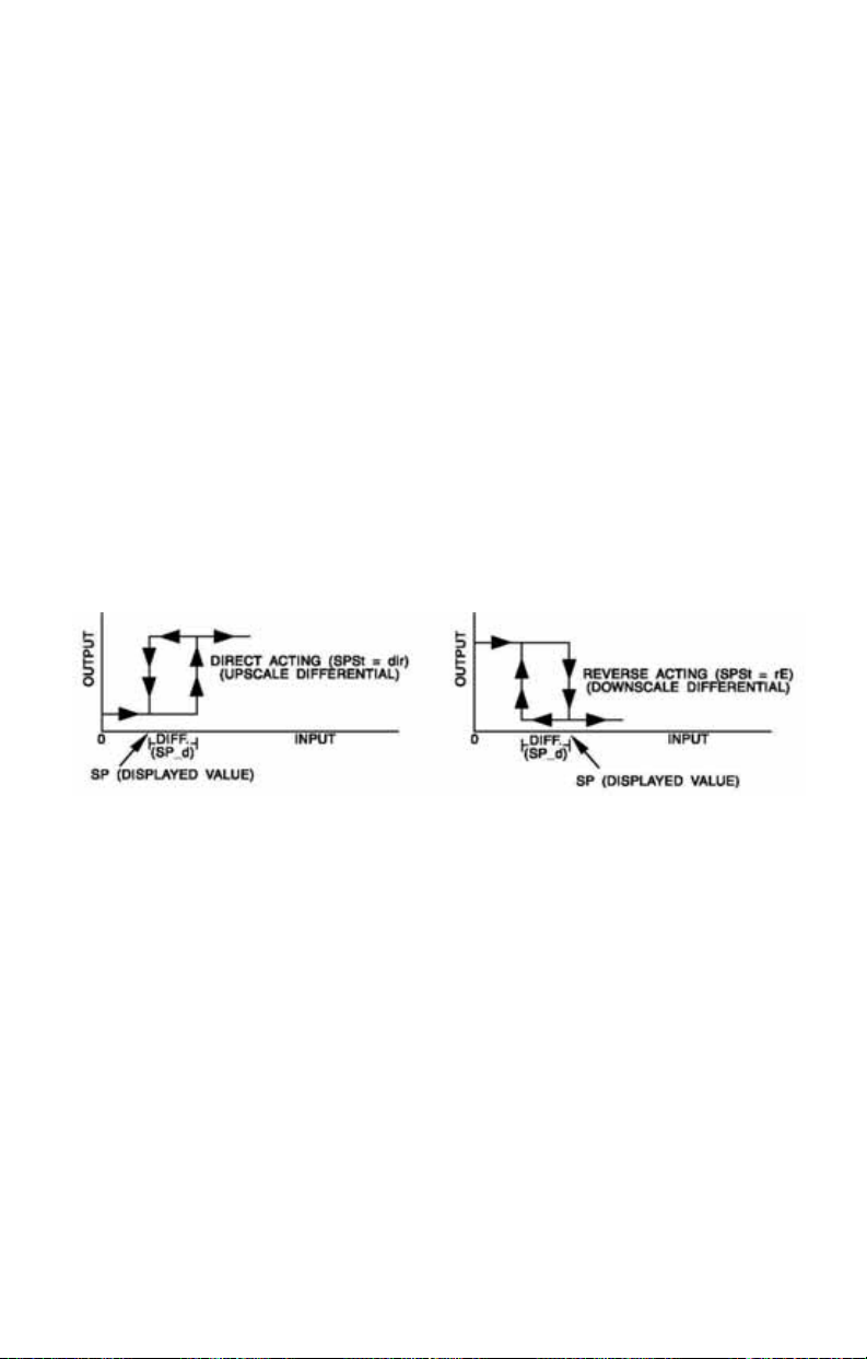
SP1d Set Point On-Off Differential (hysteresis). Select 1
to 9999 (direct acting), or -1 to -9999 (reverse
acting). This value will be negative for reverse
acting set points, and positive for direct acting
outputs. Set the value for the amount of difference
between the turn off point (set point) and the turn
on point. The following drawing shows output
behavior for reverse and direct action.
tP Time Proportioning Cycle Time. Select 1tP to 80tP.
##
1tP A setting of 1tP is recommended for solid state
outputs (SSR, DC SSR, or 5VDC).
2tP to 80tP Time Proportioning Control is adjustable in 1
second steps. Recommended for mechanical
outputs (relays, solenoids, etc.). For best contact
life, a time should be selected as long as possible
without causing the process to wander.
PuL Pulsed Time Proportioning Output: Select 1PuL to
#
7PuL. 1PuL = Linear and 7PuL = most nonlinear.
Changes output linearity for use in cooling
applications or for an extremely fast response
processes. At the center of the proportional band,
a pulse value of 1 provides an output of one
second on and one second off (50% output)l. A
Page 17 of 40
Page 20

pulse value of 2 provides an output of one second
on and two seconds off (33% output). Output at
center of band equals one second on, 2
seconds off.
ProP For Current (Code 5) outputs only.
tun1 Tuning Choice: Select SELF, Pid, SL0, nor, or FASt.
SELF The instrument will evaluate the Process and select the
PID values to maintain good control.
Active for SP1 only.
Lrn1 Select YES or no
YES Start Learning the Process. After the
process has been learned the menu item
will revert to no.
no Learning will stay in present mode.
dFC1 Damping factor, Select 0FF, 1 to 7. Sets the ratio
of Rate to Reset for the
SELF tunE mode. 7 =
most Rate. Factory set to 3. For a fast response
process the value should be lowered (less Rate).
For a slower process the value should be
increased (more Rate).
Pid Manually adjust the PID values. PID control consists of
three basic parameters, Proportional Band (Gain), Reset
Time (Integral), and Rate Time (Derivative).
Pb1 Proportional Band (Bandwidth). Select 1 to
9999 ˚F, ˚C, or counts.
rES1 Automatic Reset Time. Select 0FF, 0.1 to 99.9
minutes. Select 0FF to switch to 0FS1.
0F51 Manual Offset Correction Select 0FF, 0.1 to
99.9%. Select 0FF to switch to rES1.
rtE1 Rate Time. Select 0FF, 0.01 to 99.99 minutes,
Derivative.
SL0 PID values are preset for a slow response process.
nor PID values are preset for a normal response process.
FASt PID values are present for a fast response process.
(pulse value -1)
ArS1 Anti-Reset Windup Feature: Select 0n or 0FF.
0n Reset Offset value will be cleared to 0% when the process
input is not within the Proportional Band.
0FF Reset Offset Value is retained in memory when the
process input is not within the Proportional Band.
Page 18 of 40
Page 21

Art1 Approach Rate Time: Select 0FF, 0.01 to 99.99 minutes. The
function defines the amount of Rate applied when the input is out
side of the Proportional band. The
Art1 time and the rtE1 time
are independent and have no effect on each other. To increase
damping effect and reduce overshoot set the approach rate time
for a value greater than the natural rise time of the process
(natural rise time = process value time to set point).
Fi1 Fuzzy Logic Intensity: Select 0 to 100%. 0% is OFF (disables
Fuzzy Logic). The function defines the amount of impact Fuzzy
Logic will have on the output. If
Fi1 is set to 0, Fbd1 and Frt1
below will not appear.
Fbd1 Fuzzy Logic Error Band: Select 0 to 4000 ˚F, ˚C, or counts. Sets
the bandwidth of the Fuzzy Logic. Set
proportional band (
Pb1) for best results. Self Tune, when used,
calculates this value. Will not appear if
Frt1 Fuzzy Logic Rate of Change: Select 0.00 to 99.99
Fbd1 equal to PID
Fi1 is 0.
counts/second. For best initial setting, find the count/second
change of process value near Set Point 1 with output ON (100%
output). Multiply this value by 3. Set
Frt1 to this calculated value.
Self Tune, when used, calculated this value. Will not appear if
Fi1 is 0.
PEA1 The Peak feature stores the highest input the control has
measured for Zone 1 since the last reset or Power On. At Power
PEA1 is reset to the present input value. To manually reset
On,
the value
key to reset.
PEA1 must be in the lower display. Press the ENTER
PEA1 will be reset and display the present input
value.
UAL1 The Valley feature stores the lowest input the Instrument has
measured for Zone 1 since the last reset or Power On. At Power
UAL1 is reset to the present input. To manually reset the
On,
UAL1 must be in the lower display. Press the ENTER key.
value
UAL1 will be reset and display the present input value.
Page 19 of 40
Page 22

1nC1 Input Correction: Select -500 to 500 ˚F, ˚C, or counts.
This feature allows the input value to be changed to agree with
an external reference or to compensate for sensor error.
Note: 1nC1 is reset to zero when the input type is changed, or
when decimal position is changed.
iL1 Digital Filter: Select 0FF, 1 to 99. In some cased the time
F
constant of the sensor, or noise could cause the display to jump
enough to be unreadable. A setting of
provide enough filtering for most cases, (
2 is usually sufficient to
2 represents
approximately a 1 second time constant). When the 0.1 degree
resolution is selected this should be increased to
4. If this value is
set too high, controllability will suffer.
LPb1 Loop Break Protection: Select 0FF, 1 to 9999 seconds. If, during
operation, the output is minimum (0%) or maximum (100%), and
the input moves less than 5˚F (3˚C) or 5 counts over the time set
LPb1, the L00P bAd message will appear. The loop break
for
error can be reset by pressing the ENTER key when at the
LPb1
menu item. The INDEX & ENTER keys may also be used.
Page 20 of 40
Page 23
If Edit is set to 1, jump to LorE on page 24.
Edit is set to 3, continue.
If
Edit is set to 2, begin.
If
0ut2 Output selection: Select 0n0F, 1tP, or 1PuL.
0n0F A setting of 0n0F allows the control to operate as a
simple on/off mode. This setting forces the control to turn off at
set point, and on at the set point plus the differential (
When selected, the
SP2d, and the tun2, Pb2, rES2, 0F52, rtE2, and
####/
Ar52 selections in the Secondary menu and the 520L and
520H selections in the Secure menu are suppressed.
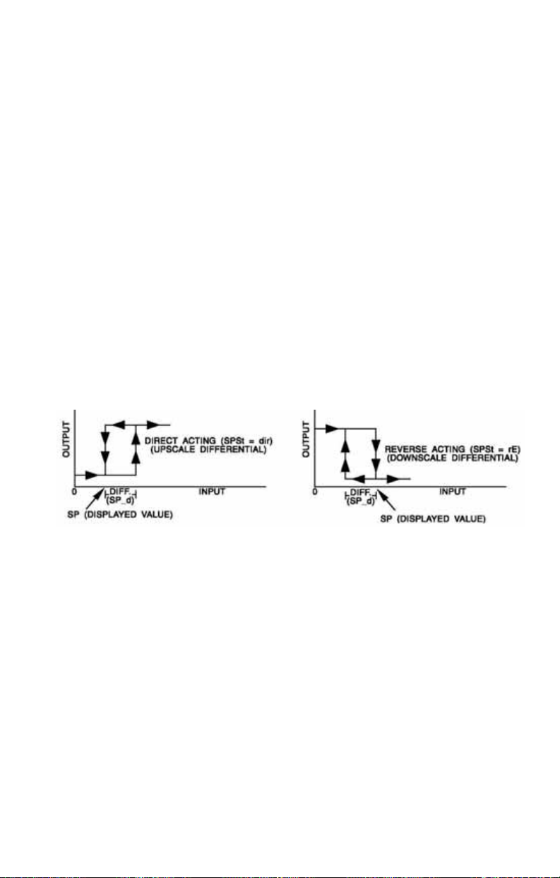
SP2d Set Point On-Off Differential (hysteresis). Select 1 to
9999 (direct acting), or -1 to -9999 (reverse acting).
0ut2/0n0F menu item is followed by
This value will be negative for reverse acting set points,
and positive for direct acting outputs. Set the value for the
amount of difference between the turn off point (set point)
and the turn on point. The following drawing shows output
behavior for reverse and direct action.
SP2d).
tP Time Proportioning Cycle Tine. Select 1tP to 80tP.
##
1tP A setting of 1tP is recommended for solid state outputs
(SSR, DC SSR, or 15VDC).
2tP to 80tP Time Proportioning Control is adjustable in 1
second steps. Recommended for mechanical outputs
(relays, solenoids, etc.). For best contact life, a time
should be selected as long as possible with causing the
process to wander.
PuL Pulsed Time Proportioning Output: Select 1PuL to 7PuL.
#
1PuL = Linear and 7PuL = most nonlinear. Changes
output linearity for use in cooling applications or for an
extremely fast response processes. At the center of the
proportional band, a pulse value of 1 provides an output of
one second on and one second off (50% output). A pulse
Page 21 of 40
Page 24

value of 2 provides an output of one second on and two
seconds off (33% output). Output at center of band equals
one second on, 2
tun2 Tuning Choice: Select SELF, Pid, SL0, nor, or FASt.
SELF The Controller will evaluate the Process and select the
(pulse value -1)
seconds off.
PID values to maintain good control.
Lrn2 Select YES or no
YES Start Learning the Process. After the
process has been learned the menu item
will revert to
no Learning will stay in present mode.
dFC2 Damping factor, Select 0FF, 1 to 7. Sets the ratio
of Rate to Reset for the
most Rate. Factory set to
no.
SELF tunE mode. 7 =
3. For a fast response
process the value should be lowered (less Rate).
For a slower process the value should be
increased (more Rate).
Pid Manually adjust the PID values. PID control consists of
three basic parameters, Proportional Band (Gain), Reset
Time (Integral), and Rate Time (Derivative).
Pb2 Proportional Band (Bandwidth). Select 1 to
9999 ˚F, ˚C, or counts.
rES2 Automatic Reset Time. Select 0FF, 0.1 to 99.9
minutes. Select 0FF to switch to 0F52.
0F52 Manual Offset Correction Select 0FF, 0.1 to
99.9%. Select 0FF to switch to rES2.
rtE2 Rate Time. Select 0FF, 0.01 to 99.99 minutes,
Derivative.
SL0 PID values are preset for a slow response process.
nor PID values are preset for a normal response process.
FASt PID values are preset for a fast response process.
Ar52 Anti-Reset Windup Feature: Select 0n or 0FF.
0n Reset Offset value will be cleared to 0% when the process
input is not within the Proportional Band.
0FF Reset Offset Value is retained in memory when the
process input is not within the Proportional Band.
Page 22 of 40
Page 25

Art2 Approach Rate Time: Select 0FF, 0.01 to 99.99 minutes. The
function defines the amount of Rate applied when the input is out
side of the Proportional Band. The Art2 time and the rtE2 time are
independent and have no effect on each other. To increase
damping effect and reduce overshoot set the approach rate time
for a value greater than the natural rise time of the process
(natural rise time = process value time to set point).
Fi 2 Fuzzy Logic Intensity: Select 0 to 100%. 0% is OFF (disables
Fuzzy Logic). The function defines the amount of impact Fuzzy
Logic will have on the output. If
F ı 2 is set to 0, Fbd2 and Frt2
below will not appear.
Fbd2 Fuzzy Logic Error band: Select 0 to 4000 ˚F, ˚C, or counts. Sets
the bandwidth of the Fuzzy Logic. Set
proportional band (
Pb2) for best results. Self Tune, when used,
calculates this value automatically. Will not appear if
0.
Frt2 Fuzzy Logic Rate of Change: Select 0.00 to 99.99
Fbd2 equal to PID
F ı 2 is set to
counts/second. For best initial setting, find the count/second
change of process value near set point 1 with output ON (Output
is 100%). Multiply the value by 3. Set
Frt2 to this calculated
value. Self Tune, when used, calculates this value automatically.
Will not appear if
Fi2 is set to 0.
PEA2 The Peak feature stores the highest input the control has
measured for Zone 2 since the last reset or Power On. At Power
PEA2 is reset to the present input. To manually reset the
On,
PEA2 must be in the lower display. Press the ENTER key
value
to reset.
UAL2 The Valley feature stores the lowest input the Instrument has
PEA2 will be reset and display the present input value.
measured for Zone 2 since the last reset or Power On. At Power
UAL2 is reset to the present input. To manually reset the
On,
UAL2 must be in the lower display. Press the ENTER key.
value
UAL2 will be reset and display the present input value.
Page 23 of 40
Page 26

1nC2 Input Correction: Select -500 to 500 ˚F, ˚C, or counts. This
feature allows the input value to be changed to agree with an
external reference or to compensate for sensor error. Note:
1nC2
is reset to zero when the input type is changed, or when decimal
position is changed.
FiL2 Digital Filter: Select 0FF, 1 to 99. In some cases the time
constant of the sensor, or noise could cause the display to jump
enough to be unreadable. A setting of
provide enough filtering for most cases, (
2 is usually sufficient to
2 represents
approximately a 1 second time constant). When the 0.1 degree
resolution is selected this should be increased to
4. If this value is
set too high, controllability will suffer.
LPb2 Loop break Protection: Select 0FF, 1 to 9999 seconds. If, during
operation, the output is minimum (0%) or maximum (100%), and
the input moves less than 5˚F (3˚C) or 5 counts over the time set
for LPb2, the
error can be reset by pressing the ENTER key when at the
L00P bAd message will appear. The loop break
LPb2
menu item. The INDEX & ENTER keys may also be used.
The following Menu Items operate on the entire instrument. There is
no Zone or Set Point distinction. They will appear in the
Edit2, and Edit3 menus.
Edit1,
L0rE
L0C
(Option C4, Serial Communications) Local / Remote Status: Select
or rE.
L0C
The host computer is advised not to send remote
commands. Any write commands sent to the controls will
be rejected.
rE
The host computer is allowed to send write commands. If
the control is not addressed within the time set in the
(No Activity Timer, see Secure Menu) the
CHEC LorE
error message will be displayed.
Addr (Option C4, Serial Communications) Control Address: Read value
3FF
from 1 to
. This number (hexadecimal, base 16) must match
the address number used by the host computer. Viewed only in
this menu. The value displayed is for Zone 1. The address for
17
Zone 2 is the value for Zone 1 plus one (e.g. if Addr is set to
Zone 1 is assigned to address
address
Page 24 of 40
17
and Zone 2 is assigned to
18
). To change this parameter, see
Addr
in the Secure Menu.
,
nAt
Page 27

SECURE MENU
Hold UP ARROW & ENTER for 5 Seconds. Press INDEX to advance to
the next menu item. Press UP ARROW or DOWN ARROW to change
the value in the display. Press ENTER to retain the value. OUTPUTS
ARE DISABLED (TURNED OFF) WHILE THE INSTRUMENT IS IN
SECURE MENU.
Edit is set to 0, begin.
If
Edit is set to 1 or 3, jump to SEC1 on page 26.
If
Edit is set to 2, jump to SEC2 on page 29.
If
Note: There are no standard menu items for the Secure Menu when
Edit is set to 0.
Addr (Option C4, Serial Communications) Control Address: Select
1
to
3FE
from
. This number (hexadecimal, base 16) must match
the address number used by the host computer. The value
displayed is for Zone 1. The address for Zone 2 is the value for
Zone 1 plus one (e.g. if
17
address
100, 200
and Zone 2 is assigned to address 18). Addresses
, and
300
are reserved for Factory use.
Addr
is set to 17, Zone 1 is assigned to
bAUd
(Option C4, Serial Communications) Communication Baud
Rate: Select
300, 1200, 2400, 4800, 9600
, or
19200
. This
number must match the baud rate used by the host computer.\
nAt (Option C4, Serial Communications) No Activity Timer: Set from
0FF
or 1to 99minutes.
1-99
0FF
End of Secure Menu when
Page 25 of 40
Maximum time between host computer accesses. If timer
counts to 0,
CHEC LorE
will be displayed.
No Activity Timer function is disabled.
Edit is set to 0.
Page 28

If Edit is set to 1 or 3, begin.
Edit is set to 2, jump to SEC2 on page 30.
If
SEC1 Security Code: See the Security Level Selection and the Password
Table in this manual, in order to enter the correct password.
1nP1 Input Type: Select one of the following. Refer to the Input wiring
selection for the proper wiring.
J-1C Type “J” Thermocouple
CA Type “K” Thermocouple
Input Group 1
0SP1 Zero Suppression: Select 0n or 0FF. Only with Current and
E- Type “E” Thermocouple
L- Type “L” Thermocouple
n- Type “N” Thermocouple
Voltage input types
0FF The input range will start at 0 (zero) Input.
0n The input range will start at 4.00 mA or 2.00 V.
Unt1 F, C or nonE
F
˚F lamp is On and temperature inputs will be displayed in
degrees Fahrenheit.
C ˚C lamp is On and temperature inputs will be displayed in
degrees Celsius.
nonE Both the ˚F and ˚C lamps will be Off. This selection is only
available with Current and Voltage Inputs.
Page 26 of 40
Page 29

Note: If both Set Point 1 and Set Point 2 are set for temperature inputs,
they must both be set for the same scale. While it is possible to set one
input as degrees F and the other degrees C, as there is only one
descriptor, one of the displays is likely to be mis-read. If one Set Point is
set for process input, you may select to display either the temperature
descriptor or neither (nonE).
dPt1 Decimal Point Positioning: Select 0, 0.0, 0.00, or 0.000. On
temperature type inputs this will only effect the Process Value,
SP1 and 1nC1. For Current and Voltage Inputs all Menu Items
related to the Input will be affected.
0 No decimal Point is selected. This is available for all Input
Types.
0.0 One decimal place is available for Type J, K, E, T, L,
RTD’s, Current and Voltage Inputs.
0.00 Two decimal places is only available for Current and
Voltage Inputs.
0.000 Three decimal places is only available for Current and Voltage
inputs.
1nt1 Input Fault Timer: Select 0FF, 0.1 to 540.0 minutes. Whenever
an Input is out of range (
UFL or 0FL displayed), shorted, or open
the timer will start. When the time has elapsed, the instrument will
disable the output(s) and display
bAd 1nP. If 0FF is selected, the
Input Fault Timer will not be recognized (time = infinite).
SEn1 Sensor Rate of Change: Select 0FF, 1 to 4000 ˚F, ˚C, or counts
per 1 second period. This value is usually set to be slightly
greater than the fastest process response expected during a 1
second period, but measured for at least 2 seconds. If the
process is faster than this setting, the
SEn1 bAd error message
will appear. The outputs will then be turned off. This function can
be used to detect a run away condition, or speed up detection of
an open thermocouple. Use the INDEX & ENTER keys to reset.
SCL1 Scale Low: Select 100 to 9999 counts below SCH1. The total
span between
Maximum setting range is
SCL1 and SCH1 must be within 11998 counts.
-1999 to 9999 counts. Minimum
span is 100 counts. For Current and Voltage inputs, this will set
the low range end. Viewable only for Thermocouple and RTD
ranges.
Page 27 of 40
Page 30

SCH1 Scale High: Select 100 to 9999 counts above SCL1. The total
span between
Maximum setting range is
SCL1 and SCH1 must be within 11998 counts.
-1999 to +9999 counts. Minimum
span is 100 counts. For Current and Voltage inputs, this will set
the high range end. Viewable only for Thermocouple and RTD
ranges.
SPL1 Set Point Low: Select from the lowest input range value to SPH1
value. This will set the minimum SP1 value that can be entered.
The value for SP1 will not stop moving when this value is reached.
Attempting to set a value for
CHEC SP1 error. The value will not be accepted.
SPH1 Set Point High: Select from the highest input range value to SPL1
SP1 lower than SPL1 will result in a
value. This will set the maximum SP1 value that can be entered.
The value for
Attempting to set a value for
CHEC SP1 error. The value will not be accepted.
515t Set Point State: Select dir or rE.
dir Direct Action. As the input increase the output will increase.
SP1 will not stop moving when this value is reached.
SP1 higher than SPH1 will result in a
Most commonly used in cooling processes.
rE Reverse Action. As the input increases the output will
decrease. Most commonly used in heating processes.
0ut1 is set for ##tP, #PUL, or ProP, then S10L and S10H (following)
If
appear. If
510L Set Point Output Low Limit: Select 0 to 90% but not greater than
0ut1 is set for 0n0F, then skip to 51rE.
510H. This item limits the lowest output value. This is useful for
adding a bias to the process when needed. Factory set to
put codes 1, 2, 3, and 8. Factory set to
20 for output code 5 (20%
0 for out
output equals 4 mA output).
510H Set Point Output High Limit: Select 10 to 100% but not less than
510L for output codes 1, 2, 3, or 8. Select 10 to 102% but not less
than S10L for output code 5. This item allows setting the maximum
output limit. This is useful with processes that are over powered.
Adjustment to
102% allows setting current output to force a full on
condition for output devices which do not have bias adjustments.
Factory set to
Page 28 of 40
100 for all output codes.
Page 31

If 0ut1 is set for ##tP, #PUL, or ProP, then skip to 51LP.
51rE Set Point Reset. Select 0n0F or HoLd.
0n0F Control will automatically reset when process passes back
through
HoLd Manual Reset. Reset (acknowledge) by simultaneously pressing
the INDEX & DOWN ARROW keys for 5 seconds.
SP1d.
S1Pi
Set Point Power Interrupt. Select 0n or 0FF.
0n Alarm Power Interrupt is 0n. Control will automatically
reset on power-up if no alarm condition exists.
0FF Alarm Power Interrupt is 0FF. Control will power-up in
alarm condition regardless of condition of process.
51iH Set Point Inhibit: Select 0n or 0FF.
0n Alarm Inhibit is 0n. Alarm action is suspended until the
process value first enters a non-alarm condition.
0FF Alarm Inhibit is 0FF.
S1LP Set Point Lamp: Select O on or OoFF.
0on Lamp ON when Output on 0n.
0oFF Lamp OFF when Output is 0n.
If
Edit is set to 1, jump to Addr on page 33.
If
Edit is set to 3, continue.
Page 29 of 40
Page 32

If Edit is set to 1, Jump to SP1o on page 33.
Edit is set to 3, continue.
If
Edit is set to 2, begin.
If
SEC2 Security Code: See the Security Level Selection and the Password
Table in this manual, in order to enter the correct password.
1nP2 Input Type: Select one of the following. Refer to the Input wiring
selection for the proper wiring.
J-1C Type “J” Thermocouple
CA Type “K” Thermocouple
Input Group 1
Unt2 F, C or nonE
F ˚F lamp is On and temperature inputs will be displayed in
E- Type “E” Thermocouple
L- Type “L” Thermocouple
n- Type “N” Thermocouple
degrees Fahrenheit.
C ˚C lamp is On and temperature inputs will be displayed in
degrees Celsius.
nonE Both the ˚F and ˚C lamps will be Off. The selection is only
available with Current and Voltage Inputs.
Page 30 of 40
Page 33

Note: If both Set Point 1 and Set Point 2 are set for temperature inputs,
they must both be set for the same scale. While it is possible to set one
input as degrees F and the other degrees C, since there is only one
descriptor, one of the displays is likely to be mis-read. If one Set Point is
set for process input, you may select to display either the temperature
descriptor or neither (nonE).
dPt2 Decimal Point Positioning: Select 0, 0.0. This will only effect the
Process Value, SP1, SP2, and InC1llnC2.
0 No decimal Point is selected.
0.0 One decimal place is available for Type J, K, E, T, L, Inputs.
1nt2 Input Fault Timer: Select 0FF, 0.1 to 540.0 minutes. Whenever
an Input is out of range (
UFL or 0FL displayed), shorted, or open
the timer will start. When the time has elapsed, the instrument will
disable the output(s) and display
bAd 1nP. If 0FF is selected, the
Input Fault Timer will not be recognized (time = infinite).
SEn2 Sensor Rate of Change: Select 0FF, 1 to 4000 ˚F, ˚C, or counts
per 1 second period. This value is usually set to be slightly
greater than the fastest process response expected during a 1
second period, but measured for at least 2 seconds. If the
process is faster than this setting, the
SEn2 bAd error message
will appear. The outputs will then be turned off. This function can
be used to detect a run away condition, or speed up detection of
an open thermocouple. Use the INDEX & ENTER keys to reset.
SCL2 Scale Low: Select 100 to 9999 counts below SCH2. The total
span between
Maximum setting range is
SCL2 and SCH2 must be within 11998 counts.
-1999 to 9999 counts. Minimum
span is 100 counts. For Current and Voltage inputs, this will set
the low range end. Viewable only for Thermocouple and RTD
ranges.
Page 31 of 40
Page 34

SCH2
Scale High: Select 100 to 9999 counts above SCL2. The total
span between SCL2 and SCH2 must be within 11998 counts.
Maximum setting range is
-1999 to +9999 counts. Minimum
span is 100 counts. For Current and Voltage inputs, this will set
the high range end. Viewable only for Thermocouple and RTD
ranges.
SPL2 Set Point Low: Select from the lowest input range value to SPH1
value. This will set the minimum
The value for
SP2 will not stop moving when this value is reached.
Attempting to set a value for
CHEC SP2 error. The value will not be accepted.
SPH2 Set Point High: Select from the highest input range value to SPL2
SP2 value that can be entered.
SP2 lower than SPL2 will result in a
value. This will set the maximum SP1 value that can be entered.
The value for
Attempting to set a value for
CHEC SP2 error. The value will not be accepted.
525t Set Point State: Select dir or rE.
dir Direct Action. As the input increase the output will increase.
SP2 will not stop moving when this value is reached.
SP2 higher than SPH2 will result in a
Most commonly used in cooling processes.
rE Reverse Action. As the input increases the output will
decrease. Most commonly used in heating processes.
0ut2 is set for ##tP, or #PUL, then 520H and 520H (following) appear.
If
0ut2 is set for 0n0F, then skip to 52rE.
If
520L Set Point Output Low Limit: Select 0 to 90% but not greater than
520H. This item limits the lowest output value. This is useful for
adding a bias to the process when needed. Factory set to
put codes 1, 2, 3, and 8. Factory set to
20 for output code 5 (20%
0 for out
output equals 4 mA output).
520H Set Point Output High Limit: Select 10 to 100% but not less than
520L for output codes 1, 2, 3, or 8. Select 10 to 102% but not less
than S20L for output code 5. This item allows setting the maximum
output limit. This is useful with processes that are over powered.
Adjustment to
102% allows setting current output to force a full on
condition for output devices which do not have bias adjustments.
Factory set to
Page 32 of 40
100 for all output codes.
Page 35

If 0ut1 is set for ##tP, #PUL, or ProP, then skip to 51LP.
51rE Set Point Reset. Select 0n0F or HoLd.
0n0F Control will automatically reset when process passes back
through
HoLd Manual Reset. Reset (acknowledge) by simultaneously pressing
the INDEX & DOWN ARROW keys for 5 seconds.
SP2d.
S2Pi
Set Point Power Interrupt. Select 0n or 0FF.
0n Alarm Power Interrupt is 0n. Control will automatically
reset on power-up if no alarm condition exists.
0FF Alarm Power Interrupt is 0FF. Control will power-up in
alarm condition regardless of condition of process.
52iH Set Point Inhibit: Select 0n or 0FF.
0n Alarm Inhibit is 0n. Alarm action is suspended until the
process value first enters a non-alarm condition.
0FF Alarm Inhibit is 0FF.
S2LP Set Point Lamp: Select O on or OoFF.
0on Lamp ON when Output on 0n.
0oFF Lamp OFF when Output is 0n.
52t Set Point 2 type: Select Ab5 or dE.
Ab5 Absolute 5P2. 5P2 is independent of SP1, and may be set
anywhere between the limits of
dE Deviation 5P2. 5P2 is set as a deviation from SP1, and
allows
5P2 to retain its relationship with SP1 when SP1 is
SPL2 and SPH2.
changed.
Note: The
SPL1 and SPH1 settings. If not, a CHEC SP2 error may be generated by
a change of
SPL2 and SPH2 settings must be sent to correspond with the
SP1.
Page 33 of 40
Page 36

The following Menu Items operate on the entire Instrument. There is
no Set Point distinction. These items will appear in both the
Edit2, and Edit3 menus.
SP1o Set Point 1 Output Select: Select 0utA or 0utb.
0utA Set Point 1 is routed through Output A, Set Point 2 is
Edit1,
routed through Output B.
0utb Set point 1 is routed through Output B, Set Point 2 is
routed through Output A.
C0PY Copy Zone Parameters. Copies program parameters from one
zone to the other.
nonE No copy function is performed. Factory default.
1to2 Copies all parameters from Zone 1 to Zone 2.
2t01 Copies all parameters from Zone 2 to Zone 1.
Addr (Option C4, Serial Communications) control Address: Select from
1
to
3FE
. This number (hexadecimal, base 16) must match the
address number used by the host computer. The value displayed
for Zone 1. The address for Zone 2 is the value for Zone 1 plus one
(e.g. if
Addr
Zone 2 is assigned to address
300
are reserved for Factory use.
is set to 17, Zone 1 is assigned to address 17and
18
). Addresses
100, 200
, and
bAUd (Option C4, Serial Communications) Communication Baud Rate:
300
,
Select
1200, 2400, 4800, 9600
, or
19200
. This number
must match the baud rate used by the host computer.
nAt (Option C4, Serial Communications) No Activity Timer: Set from
0FF
or 1 to 99minutes.
1-99 Maximum time between host computer accesses. If timer
0FF No Activity Timer function is disabled.
Page 34 of 40
counts to
0, CHEC LorE
will be displayed.
Page 37

SPECIFICATIONS
Input: Thermocouple.
Input Impedance: Thermocouple = 3 megohms minimum.
Sensor Break Protection: De-energizes control output to protect system
after customer set time. (See InP1 and InP2 in Secondary Menu.)
Set Point Range: Selectable (See Range Chart Page 39).
Display: Two 4 digit, 7 segment 6.35 mm (0.25˝) high LEDs.
Control Action: Reverse (usually heating), Direct (usually cooling) selec-
table.
Proportional band: 1 to 9999 ˚F, ˚C, or counts.
Reset Time (Integral): Off or 0.1 to 99.9 minutes.
Rate Time (Derivative): Off or 0.01 to 99.99 minutes.
Cycle Rate: 1 to 80 seconds.
On-Off Differential: Adjustable 1˚F, 1˚C, or 1 count to full scale in 1˚F,
1˚C, or 1 count steps.
Fuzzy Percent: 0 to 100%
Fuzzy Band: Off or 1 to 4000 ˚F, ˚C, or counts.
Accuracy: ±0.25% of span, ±1 least significant digit.
Resolution: 1 degree or 0.1 degree, selectable.
Line Voltage Stability: ±0.05% over the supply voltage range.
Temperature Stability: 100 ppm / ˚C typical, 200 ppm / ˚C maximum.
Common Mode Rejection: 140 db minimum at 60 Hz.
Isolation:
Relay outputs: 1500 Vac to all other inputs and outputs
Supply Voltage: 100 to 240 Vac, nominal, +10-15%, 50 to 400 Hz. single
phase; 132 to 240 Vdc, nominal, +10-20%.
Supply Voltage (Option LV): 12 to 24 Vdc, Vac 40-400 Hz, ±20%.
Power Consumption: 5VA maximum.
Operating Temperature: -10 to +55 ˚C (+14 to 131 ˚F).
Page 35 of 40
Page 38

Storage Temperature: -40 to +80 ˚C (-40 to 176˚F).
Humidity Conditions: 0 to 90% up to 40 ˚C non-condensing, 10 to 50%
at 55 ˚C non-condensing.
Memory Backup: Nonvolatile memory. No batteries required.
Control Output Ratings:
Relay (Output A, Output B): SPST, 3A @ 240 Vac resistive;
1.5A @ 240 Vac inductive; 1/10 HP @ 120 Vac.
Switched Voltage (non-isolated, Output A, Output B):
5 Vdc @ 20 mA.
Current (Isolated): 0 to 20 mA across 600 ohms maximum.
Panel Cutout: 45.0 mm x 22.2 mm (1.772˝ x 0.874˝).
Depth Behind Mounting Surface: 111.6 mm (4.395˝).
Weight: 114 g (4 oz).
Agency Approvals: UL and C-UL, file #E83725; CE.
Front Panel Rating: IP66, Type 4.
Page 36 of 40
Page 39

DISPLAY
DIAGNOSTIC ERROR MESSAGES
MEANING
SP OUTPUTS
ACTION REQUIRED
No
display lighted
FA1L
tESt
CHEC SP1
CHEC SP2
CHEC SPL1
CHEC SPH1
or
CHEC SPL2
CHEC SPH2
Display is blank.
Instrument is not
getting power, or the
supply voltage is too
low.
Fail test appears upon
power up if the internal
diagnostics detect a
failure. This message
may occur during operation if a
failure is detected.
Displays flash.
This message will
appear upon power up
if SP1 is set outside of
the SPL1/SPH1
values or SP2 is set
outside the
SPL2/SPH2
values.
This message appears
at power up if SPL or
SPH values are
programmed
outside the input range
ends.
Setpoint
outputs inactive
Alarm inactive
Setpoint
outputs inactive
Alarm inactive
Setpoint
output(s)
inactive Alarm
active
Setpoint
output(s)
inactive
Alarm inactive
Check that the power supply is on,
or that the external fuses are good.
The display alternatives between
FA1L tESt and one of the following messages: FACt dFLt:
Memory may be corrupted. Press
the ENTER key and the DOWN
ARROW key to start the factory
default procedure. Recheck controller programming. rEtFACt:
Unrecoverable error, return to factory for service.
Correct the SP1, SP2. or adjust
the SPL1, SPL2, SPL2, or
SPH2 values by programming new
values.
Correct the SPL1, SPH1, SPL2, or
SPH2 values by programming new
values.
CHEC
LorE
SEnC
ArEA
(Alternates
with
PV when near)
Page 37 of 40
This message appears
if the Serial
Communications has
timed out.
Sensor Rate of
Change exceeded the
programmed limits set
for SEnC. Appears in
display of affected
zone.
This message appears
if the ambient temperature of the control is
near or out of range or
RJC sensor is broken.
Setpoint
outputs active
Alarm inactive
Setpoint
outputs active
Alarms active
Setpoint
outputs active
Alarms active
Restore the communications line
and switch the LorE to L0C.
Check for the cause of the error.
The value setting may be too slow
for the process, or the
sensor is intermittent. Correct the
problem and press INDEX and
ENTER to reset.
Correct the ambient temperature
conditions. Ventilate the area of the
cabinet or check for clogged filters.
If RJC broken, return to factory for
service.
Page 40

DISPLAY
DIAGNOSTIC ERROR MESSAGES
MEANING
SP OUTPUTS
ACTION REQUIRED
UFL*
or
0FL*
0PEn*
L00P*
CHEC SPL1
or
CHEC CAL2
Underflow or Overflow:
Process value has
exceeded input range
ends.
UFL or OFL will
sequence to display
one of these messages
if the InPt is set for a
time value.
For THERMOCOUPLE
inputs thermocouple is
open
The sensor may be
defective, heater
fuse open, heater
open, or the final
power output device
is bad.
Message appears
when input group is
selected other than
the one
provided from the
Factory
Setpoint
outputs active
Setpoint
output(s)
inactive.
Setpoint
output(s)
inactive.
Setpoint
output(s)
inactive
Alarm inactive
Input signals may normally go
above or below range ends. If not,
check input and correct.
To reset use the INDEX & ENTER
keys. When InPt (Input fault timer)
has been set for a time, the outputs
will be turned off after the set time.
Setting the timer to OFF causes the
outputs to remain active, however
UFL or OFL will still be displayed.
Correct or replace sensor. To reset
use the INDEX & ENTER keys.
Correct or replace sensor, or any
element in the control loop that may
have failed. Correct the problem,
and reset the control by pressing
the INDEX and ENTER keys, or
index to LPbr and press ENTER.
Calibrate the specified input before
putting Instrument in to service.
Check calibration
appears as an alternating
message if the
instrument
calibration nears tolerance edges.
Check calibration
appears as a
flashing meassage if
the instrument calibration exceeds
specifications.
Setpoint
outputs active
Alarm inactive
Set point
outputs active
Alarms active
Remove the instrument for
service and / or recalibration.
To reset use the INDEX &
ENTER keys.
Remove the instrument for
service and / or recalibration.
To reset use the INDEX & ENTER
keys.
* Message appears in the display of the affected zone. The output for that zone
will be inactive.
Page 38 of 40
Page 41

Input Ranges (Field Selectable)
Thermocouple Types
Input
Type
Range
1˚F
1˚C
Type J or L *
-100 to +1600
-73 to +871
Type K *
-200 to +2500
-129 to +1371
Type T *
-350 to +750
-212 to +398
Type E *
-100 to +1800
-73 to + 982
Page 39 of 40
Page 42
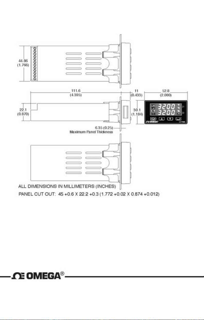
DIMENSIONS
Page 40 of 40
OMEGA Engineering
One Omega Drive
Stamford, Connecticut 06907-0047
P.O. Box 4047
Telephone: 800/848-4286; 203/359-1660
Fax: 203/359-7700
Page 43

Page 44
M4440/0207
CN 79000
FR# 08-195860-03 Rev. 2
 Loading...