

Page 1
User’s Guide
Shop online at
omega.com
e-mail: [email protected]
For latest product manuals:
www.omegamanual.info
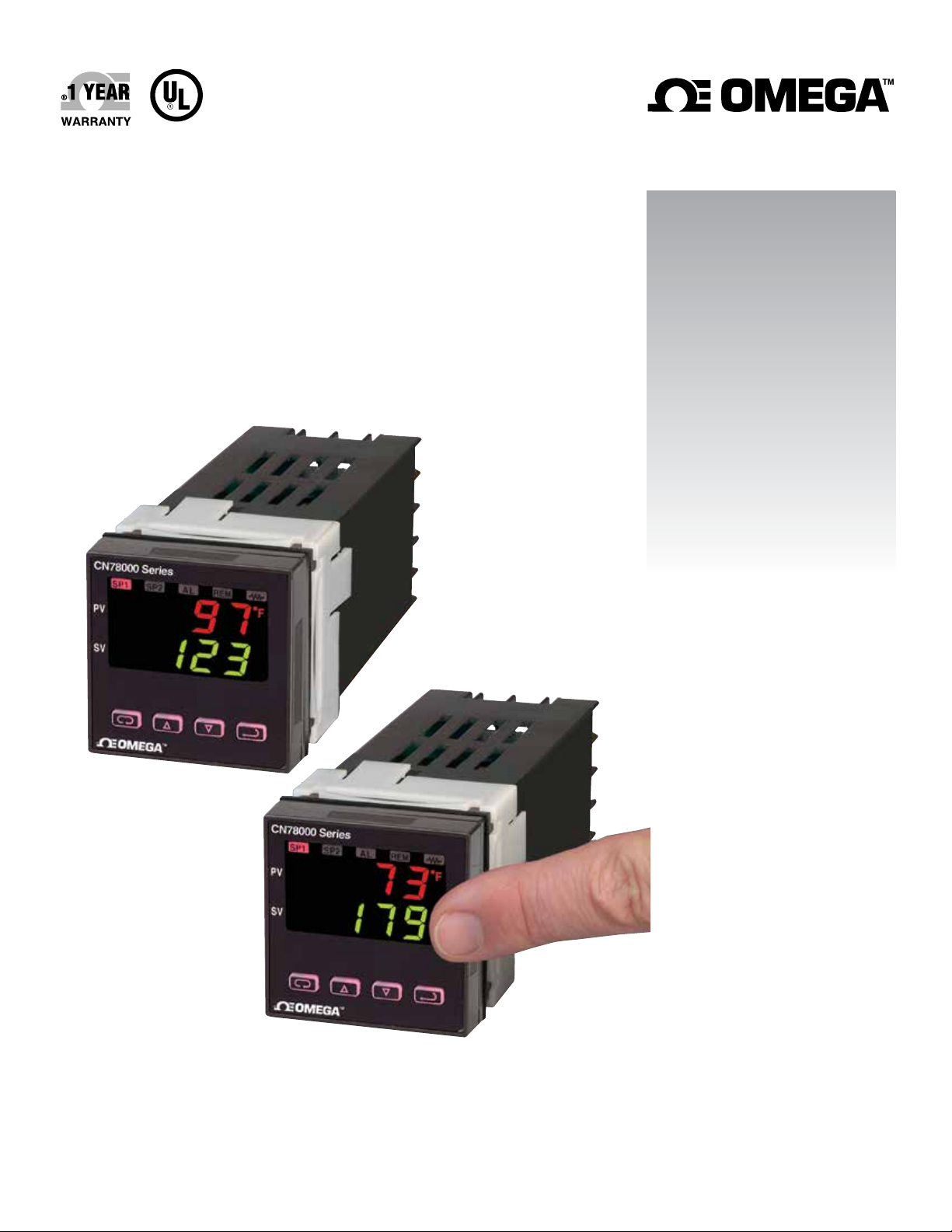
CN78000
1
⁄16 DIN Temperature/Process
Controllers with Fuzzy Logic
Page 2

omega.com [email protected]
Servicing North America:
U.S.A. Omega Engineering, Inc.
Headquarters: Toll-Free: 1-800-826-6342 (USA & Canada only)
Customer Service: 1-800-622-2378 (USA & Canada only)
Engineering Service: 1-800-872-9436 (USA & Canada only)
Tel: (203) 359-1660 Fax: (203) 359-7700
e-mail: [email protected]
For Other Locations Visit omega.com/worldwide
The information contained in this document is believed to be correct, but OMEGA accepts no liability for any errors it contains, and reserves
the right to alter specifications without notice.
Page 3

CONTENTS
GETTING STARTED . . . . . . . . . . . . . . . . . . . . . . . . . . . . . . . . . . . . . . . . . . . . . . .2
MODEL IDENTIFICATION . . . . . . . . . . . . . . . . . . . . . . . . . . . . . . . . . . . . . . . . . . .3
INSTALLATION . . . . . . . . . . . . . . . . . . . . . . . . . . . . . . . . . . . . . . . . . . . . . . . . . . .4
WIRING . . . . . . . . . . . . . . . . . . . . . . . . . . . . . . . . . . . . . . . . . . . . . . . . . . . . . . . . .5
Wiring for 4 to 20mA Transmitter Inputs . . . . . . . . . . . . . . . . . . . . . . . . . . . . . . . .6
Wiring for Optional Inputs and Outputs . . . . . . . . . . . . . . . . . . . . . . . . . . . . . . . . .6
FRONT PANEL KEY FUNCTIONS . . . . . . . . . . . . . . . . . . . . . . . . . . . . . . . . . . . . .8
Security Level Selection . . . . . . . . . . . . . . . . . . . . . . . . . . . . . . . . . . . . . . . . . . . . .9
NOTATION CONVENTIONS FOR THE MENUS . . . . . . . . . . . . . . . . . . . . . . . . . .10
THE HOME DISPLAY . . . . . . . . . . . . . . . . . . . . . . . . . . . . . . . . . . . . . . . . . . . . . .11
Program Setup and Operation . . . . . . . . . . . . . . . . . . . . . . . . . . . . . . . . . . . . . . .12
OPERATION AND PROGRAMMING OF OPTIONS . . . . . . . . . . . . . . . . . . . . . . .12
MENU SELECTIONS . . . . . . . . . . . . . . . . . . . . . . . . . . . . . . . . . . . . . . . . . . . . . .15
PRIMARY MENU . . . . . . . . . . . . . . . . . . . . . . . . . . . . . . . . . . . . . . . . . . . . . . . . .15
SECONDARY MENU . . . . . . . . . . . . . . . . . . . . . . . . . . . . . . . . . . . . . . . . . . . . . .15
SECURE MENU . . . . . . . . . . . . . . . . . . . . . . . . . . . . . . . . . . . . . . . . . . . . . . . . . .22
ALARM TYPE AND ACTION . . . . . . . . . . . . . . . . . . . . . . . . . . . . . . . . . . . . . . . .27
ERROR MESSAGES . . . . . . . . . . . . . . . . . . . . . . . . . . . . . . . . . . . . . . . . . . .31-33
SPECIFICATIONS . . . . . . . . . . . . . . . . . . . . . . . . . . . . . . . . . . . . . . . . . . . . . . . .34
DIMENSIONS . . . . . . . . . . . . . . . . . . . . . . . . . . . . . . . . . . . . . . . . . . . .Front Cover
GETTING STARTED
1. Install the control as described on page 4.
2. Wire your control following the instructions on page 5. If you are using a two-wire
transmitter as an input, see the drawing and instructions on page 6. Option wiring
instructions are on Page 7. Option descriptions and specific instructions start on
page 13.
3. Most controls do not need many (if any) program changes to work on your
process. For best results when changing the programming, make all the necessary
changes in the Secure Menu (page 22) before making changes to the Secondary
Menu (page 16). If error messages occur, check the Error Messages on page 31-33
for help.
Take the example of a Series CN78000 that comes from the factory pr ogrammed for
type J thermocouples. Suppose for this example you wish to change the input to a
100 ohm Platinum RTD and limit the set point range between 0° and 300°C.
First enter the Secure menu by pressing and holding the UP ARROW & ENTER keys
Page 2
Page 4

for 5 Seconds (see Page 22.) Press the INDEX key until the display shows 1nP
and press the DOWN ARROW until the display shows P385. Don’t forget to
press the ENTER key to retain your setting.
Next, press the INDEX key to display Unit. Press the DOWN ARROW
until the display shows C. Press ENTER.
Next, press the INDEX key until SPL is displayed (pass the dPt and 1nPt selections). Press the UP ARROW until the display shows 0. Press ENTER.
Finally, press INDEX key to display SPH. Press the DOWN ARROW until
the display shows 300. Press ENTER.
The necessary program changes are now complete. After 30 seconds the display will
switch back to the temperature reading. If you want to return faster, press the
UP ARROW and ENTER keys (at the same time) and then press the
DOWN ARROW and INDEX keys (again at the same time). This will ‘back
out’ of the menu and immediately display the temperature reading.
If you want to use Self Tune or Auto/Manual features, see the special sections on
these items. Page numbers for these are in the Contents section on the previous
page.
CN78
Alarm
0 = No
1 = Yes
Option Description
PV1* Analog Retransmission of Process Variable or Set Variable, 0 to 20 mAdc, scalable (may be
programmed for 1 to 5mA, 4 to 20 mA, etc).
PV2* Analog Retransmission of Process Variable or Set Variable, 0 to 10 Vdc, scalable.
C4* RS-485 Serial Communications, Lovelink™ protocol.
C2* RS-232 Serial Communications, Lovelink™ protocol.
LV* 12-24 Vdc/Vac 50-400 Hz power supply (control operates on low voltage equipment).
* These options may not be combined with each other.
Option LV may be combined with other options.
Output A
1 = SSR
2 = 15 VDC
3 = Relay
5 = Current
Output B
0 = None
1 = SSR
3 = Relay
Options
Pv1 = 0-20 mA
PV2 = 0-10 VDC
C4 = RS485
C2 = RS232
LV = Low Voltage
Page 3
Page 5
INSTALLATION
Mount the instrument in a location that will not be subject to excessive temperature,
shock, or vibration. All models are designed for mounting in an enclosed panel.
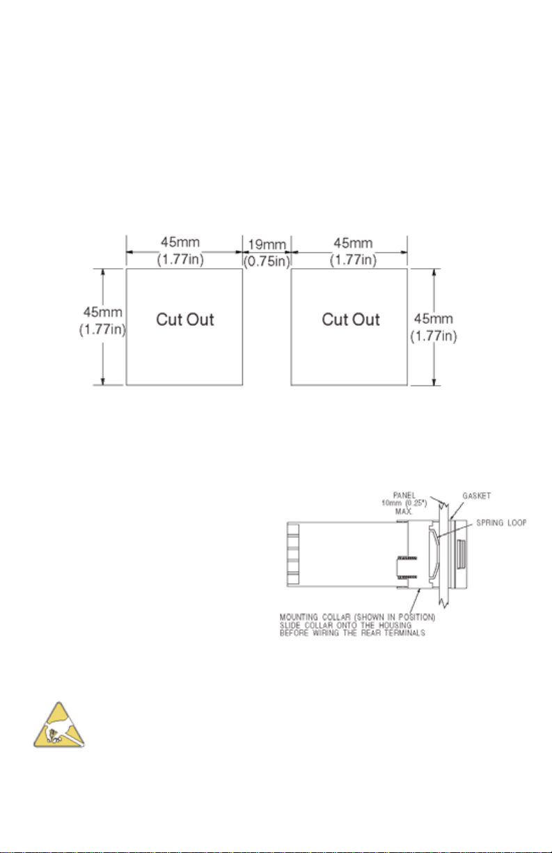
Select the position desired for the instrument on the panel. If more than one instrument is required, maintain the minimum of spacing requirements as shown on the
drawing below. Closer spacing will structurally weaken the panel, and invalidate the
IP66, UL type 4X rating of the panel.
Prepare the panel by cutting and deburring the required opening.
All Tolerances are -0.00 +0.60mm (-0.000 + 0.020 in.)
From the front of the panel, slide the housing through the cut out. The housing gasket should be against the housing flange before installing.
From the rear of the panel slide the mounting collar over the housing. Hold the housing with one hand and using the other
hand, push the collar evenly against the
panel until the spring loops are slightly
compressed. The ratchets will hold the
mounting collar and housing in place.
CAUTION: It is not necessary to remove the instrument chassis
from the housing for installation. If the instrument chassis is
removed from the housing, you must follow industry standard
practice for control and protection against Electro-Static
Discharge (ESD). Failure to exercise good ESD practices may
cause damage to the instrument.
Page 4
Page 6
WIRING
Do not run RTD, thermocouple, or other class 2 wiring in the same
conduit as power leads. Use only the type of thermocouple or
RTD probe for which the control has been programmed. Maintain
separation between wiring of sensor, optional inputs and outputs
and other wiring. See the “Secure Menu” for input selection.
For thermocouple inputs always use extension leads of the same type designated
for your thermocouple.
For supply connections use No. 16 AWG or larger wires rated for at least 75°C.
Use copper conductors only. All line voltage output circuits must hvave a common
disconnect and be connected to the same pole of the connect.
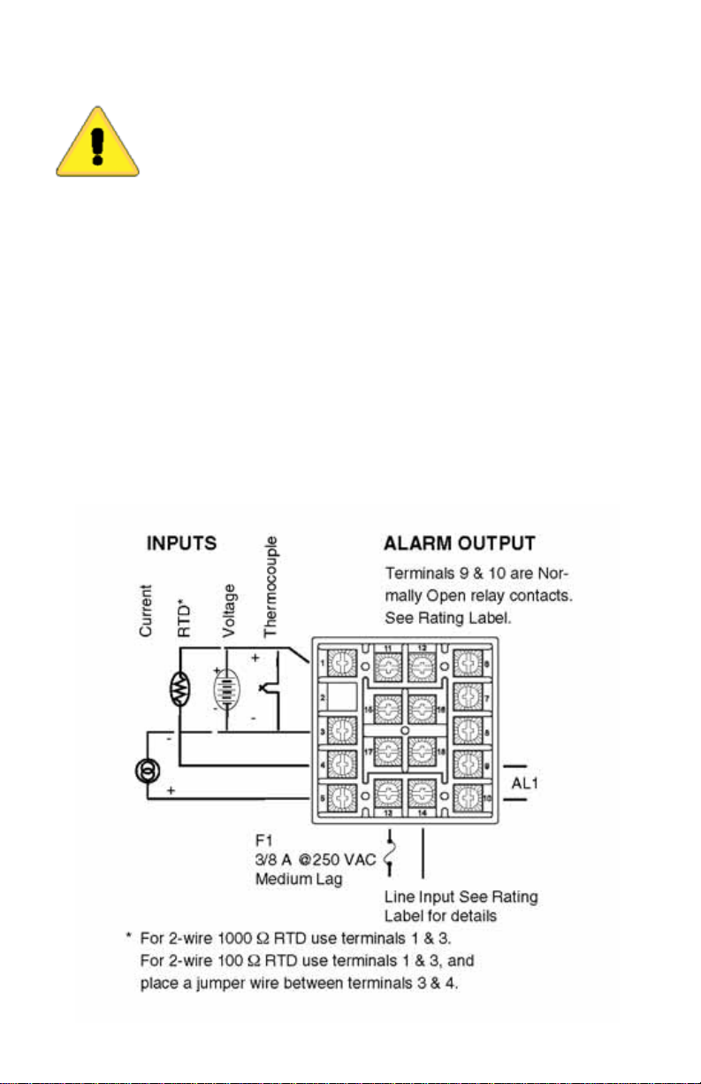
Input wiring for thermocouple, current, and RTD; and output wiring for current and
15 VDC is rated CLASS 2.
Control wiring is as shown (view is from the rear of instrument showing wiring terminals).
Page 5
Page 7
OUTPUTS
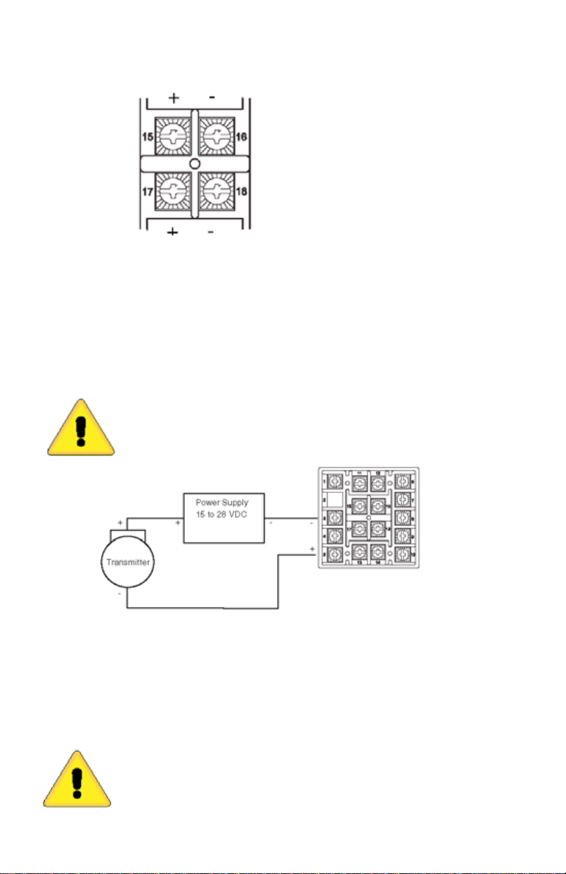
(Rear View showing center
Output A
For AC SSR or relay type outputs
(Output Codes 1 or 3), 15 & 16, and 17
& 18 are normally open. See Rating
Label for details.
Output B
Note: Factory default assigns Output A to Set Point 1 and Output B to Set Point 2.
If necessary, these realtionships may be reversed. See SP 10 in the Secure Menu.
For Pulsed DC, Current, or DC SSR
ouputs (Output codes 2, 4, or 8), 15 &
17 are positive, 16 & 18 are negative.
Wiring for 4 to 20mA Transmitter Inputs
Wiring power and ouputs as shown above. Two-wire transmitters wire as shown
below. View is of instrument as seen from the rear to show wiring terminals.
For three or four-wire transmitters, follow the wiring instructions provided with your
transmitter.
CAUTION: DO NOT WIRE THE 24 VOLT POWER SUPPLY
ACROSS THE INPUT OF THE CONTROL. DAMAGE TO THE
CONTROL INPUT CIRCUITRY WILL OCCUR.
Wiring for Optional Inputs and Outputs
Options are described on Page 3. Detailed option programming and operation
starts on Page 13. Wire power and outputs as shown on Pages 5 and 6. Wiring
for options is shown opposite. All wiring shown above is CLASS 2. Shielded twisted pair is required for Option C4. Shielded cable is required for Option C2.
CAUTION: DO NOT RUN SIGNAL WIRING IN THE SAME CONDUIT OR CHASE AS THE POWER WIRING. ERRATIC OPERATION
OR DAMAGE TO THE CONTROL CIRCUITRY WILL OCCUR.
Page 6
Page 8
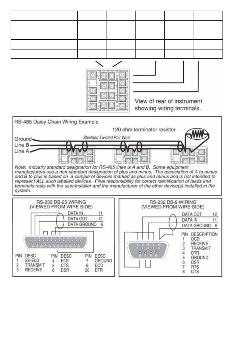
OPTION/TERMINALS
PV1 PV/SV Retransmission,
Current (e.g. 4-20 mA)
PV2 PV/SV Retransmission,
Voltage (e.g. 0-10V)
C4 RS-485 Serial Communications
C2 RS-232 Serial Communications Data In Data Out Signal Ground
11 12 6 7 8
+ + B A
na na na
na na na
na na na
na na
Page 7
Page 9
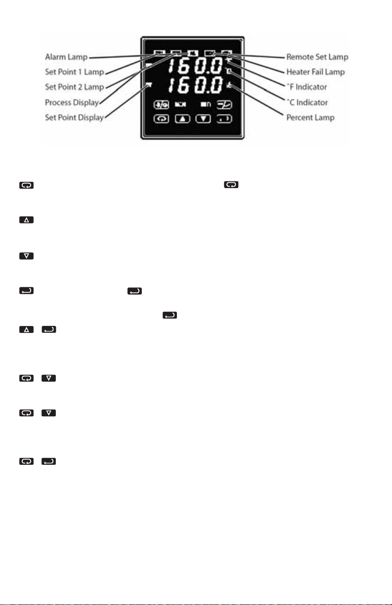
FRONT PANEL KEY FUNCTIONS
The decimal point flashes when Self Tune is operating.
Keys are illuminated when pressed. Key functions are as follows:
INDEX: Menu Navigation. Pressing the INDEX key advances the dis-
play to the next menu item. May also be used in conjunction with other
keys as noted below.
UP ARROW: Increments a value, changes a menu item, or selects the
item to ON. The maximum value obtainable is 9999 regardless of decimal
point placement.
DOWN ARROW: Decrements a value, changes a menu item, or selects
the item to OFF. The minimum value obtainable is -1999 regardless of
decimal point placement.
ENTER: Pressing ENTER stores the value or the item changed. If
not pressed, the previously stored value or item will be retained. The display will flash once when ENTER is pressed.
. UP ARROW & ENTER: Menu Access. Pressing these keys simultaneously brings up the secondary menu starting at the alarm, tune, or
cycle item (depending on programming). Pressing these keys for 5 seconds will bring up the secure menu.
. INDEX & DOWN ARROW: Menu navigation. Pressing these keys
simultaneously will allow backing up one menu item, or if at the first menu
item they will cause the display to return to the primary menu.
INDEX & DOWN ARROW: Alarm Reset. If an alarm condition has
occurred, press and hold these keys for three seconds to reset the alarm.
Note that the alarm condition will not reset if the alarm condition
still exists.
. INDEX & ENTER: ‘Global Reset’. Pressing these keys simultaneous-
ly and holding them for 5 seconds forces a ‘warm boot’, restarting the
Page 8
Page 10

control (similar to turning power off and on). ‘Global Reset’ will allow recovery from
errors and reset the following menu items:
AL iH: Alarm inhibit 0PEn 1nP: Input error
bA nP: Input err CHEC CAL: Check calibration
Correct the problems associated with the above conditions before using the reset
keys. More than one error could present. Caution is advised since several items are
reset at one time.
While in the Primary or Secondary Menu, if no key is pressed for a period of 30
seconds, the display will return to the HOME position displaying the temperature
value. While in the Secure Menu, if no key is pressed for a period of 60 seconds,
the display will return to HOME position displaying the temperature value. Outputs
are disabled (turned off) when the Secure Menu is active.
NOTE: To move the Primary Menu quickly from any other menu, press the
UP ARROW & ENTER keys followed by pressing the INDEX &
DOWN ARROW keys.
SECURITY LEVEL SELECTION
Four levels of security are provided. The display shows the current security level. To
change security levels, change the password value using the UP ARROW and
DOWN ARROW keys and press the ENTER key. Refer to the password
table for the correct value to enter for the security level desired. The SECr menu
item security level may be viewed or changed at any time regardless of the present
security level.
Example: To set security access level to 2, at the SECr menu item, press the
UP ARROW key until the upper display shows the password for level 2 access,
1101. Press the ENTER key. The display will blink and return with the level
value, 2, in the upper display.
The password values shown in the table cannot be altered, so retain a copy of
these pages for reference. This is the only reference made to password values in
this intruction book.
Page 9
Page 11

PASSWORD TABLE
Security Level
Menu Status
Displaying Value
When Viewed
Password Value To
Enter
Primary Locked
Secondary Locked
1 1110
Secure Locked
Primary Unlocked
Secondary Locked
2 1101
Secure Locked
Primary Unlocked
Secondary Unlocked
3 1011
Secure Locked
Primary Unlocked
Secondary Unlocked
4 111
Secure Unlocked
NOTATION CONVENTIONS FOR THE MENUS
Because of the number of features available in this control, information is included
that may not apply to your specific control. All usable features are included in this
book, but may not be used in your process. To increase clarity, the following conventions are used:
1. Certain features, menu items, and functions shown in this book may or may not
appear on your control, depending on other menu item selections. At various
places in the menu there are notes identifying menu items that “control” or “direct”
other menu items. If you are looking for a particular menu item and can’t find it,
check the menu item that is it’s “control” for proper setting
2. The “#” symbol is used in two ways. It is used inside group of characters to indicate which set point function (SP1 or SP2) is being affected. It is also used before
a group of characters of a menu item to indicate that there may be more than one
selection or value for that menu item. This is used for certain repeated items such
as in the Ramp/Soak Program section.
3. Features that apply only to Options will be printed in Italics.
Page 10
Page 12

THE HOME DISPLAY
The home display is the normal display while the control is operating. If no errors or
functions are active, the HOME display will indicate the Process Variable (the temperature, pressure, flow, RH, etc., that is being measured) on the top display and the
Set Variable (Set Point 1) on the bottom.
Items that can change the HOME display are the Auto/Manual function, the
Run/Hold function, the Pro9 function, the Pct0 function, and any error message.
Description of these special displays follows.
If the Auto/Manual key is pressed, the Manual indicator lights, and the home
display is changed. The upper display continues to show the Process Variable (PV),
but the lower display changes to show the percentage of output in tenths of a percent to 99.9% (0.0 to 99.9) or 100 if 100%. The display digit to the right of the number shows a flashing letter o to indicate that the value displayed is no longer the SV,
but percent output. The SP2 percent output is indicated by the use of an overline on
i
the o. Access to the SP2 value is made by the INDEX key. See Auto/ Manual
Operation on Page 14 for further information.
If Pro9 is tur ned 0n, the HOME display changes the SV display from SP1 to the
Present Set Variable as calculated by the Ramp/Soak Programmer function. See
Programming and Operation for Ramp/Soak Feature below for more information.
If Pct0 (Secondary Menu) is turned 0n, the lower display changes to show the active
percentage of output as required to maintain SP1. The display is similar to the
Auto/Manual display above, except that the percent indicators (o,o) do not flash, and
the output is displayed in whole percentages of output, not in tenths of a percent. If
the control has both SP1 and SP2, the lower display will alternate between the SP1
percent output and the SP2 percent output.
i
Error messages are listed on Pages 37-39.
Page 11
Page 13

OPERATION AND PROGRAMMING OF OPTIONS
Option PV1, PV2, Isolated Analog Retransmission
The analog retransmission option allows the process variable or the Set Variable to
be sent as an analog signal to an external device. The signal may be either 0 to 10
VDC (Option PV2) or o (or 4) to 20 mADC (option PV1). THe output may be changed
in the field from one to the other by the toggle switch located on the top printed circuit board.
Wire the output as shown on page 7.
To set up the analog retransmission, first determine the scale range that the analog
signal will represent. The maximum scale is 9999°F, 5530°C, or 9999 counts. In the
Secondary Menu set
P0L for the scale value that will be represented by the high end
of the analog signal (10 Volts or 20 mA).
If you require a suppressed scale or output, use the following equations to determine
the proper setting for P0L and P0H.
K = (Highest desired scale reading - Lowest desired scale reading) /
(Maximum desired analog signal - Minimum desired analog signal).
P0H = ((Maximum possible analog output - Maximum desired analog signal) * K) /
+ Highest desired analog reading.
P0L = Lowest desired scale reading - ((Minimum desired analog output) * K).
Next select whether you want the retransmission signal to follow the Process
Variable or the Set Variable. Usually the Process Variable is sent to recor ders or other
data acquisition devices. Usually the Set Variable is sent to other contr ols to be used
as an analog remote set point. If you want the analog retransmission signal to follow
the PV, in the Secondary Menu set P0Sr to 1nP. If you want the analog retransmission signal to follow the SV, set P0Sr to SPt.
Operation is automatic. There are no further programming steps required.
Option C2, C4, Serial Communication
The serial communications options allow the control to be written to and read from
a remote computer or other similar digital device. Communication is allowed either
through a RS-485 (Option C4) port, or a RS-232 (Option C2) port.
Wire the communication lines as shown on Page 7. Wiring for the RS-485 is run from
control to control in a daisy chain fashion with a termination resistor (120 ohms)
across the transmit and receive terminals of the last control in the chain.
Select the control address and communication baud rate with the Addr and bAUd
menu items in the Secure Menu.
Page 12
Page 14

NOTE: THE BAUD RATE AND ADDRESS MENU ITEM SETTINGS WILL TAKE
EFFECT ON THE NEXT POWER UP OF THE CONTROL. BE SURE TO TURN THE
POWER TO THE CONTROL OFF AND ON BEFORE USING THE NEW BAUD RATE
AND ADDRESS VALUES.
In operation, you have the option of preventing a write command from the host computer. To prevent the host from writing to the control change the
the Secondary Menu to L0C. To allow the host to write commands to the control set
L0rE to rE. (The host does have the ability to change the L0rE state, but it is not
automatic.)
If your system depends on constant reading or writing to and from the host, you may
wish to set the No Activity Timer (nAt) to monitor the addressing of the control. When
the L0rE is set to rE and the nAt is set to any value other than Off, the control will
expect to be addressed on a regular basis. If the control is not addr essed in the time
set by the value of nAt, then the control will display the error message CHEC L0rE.
To clear the message set L0rE to L0C.
L0rE menu item in
Serial Communications
Options and Non-volitile Memory
There are many different types of memory used in computer driven devices. The
terms RAM (random access memory) and ROM (read only memory) are a couple
with which you may be familiar.
RAM is used in computers to run programs and hold data for a short period of time.
This is the memory that is used primarily in PCs. RAM is very fast and can be read
and written to over and over again.
ROM is used in computers to hold the ‘permanent’ programming that allows a PC
to start. This memory is ‘burned in’ to the chip itself and can not be changed. Unlike
RAM, however, this memory is permanent. While it can not be changed, it can not
lose its programming when power is turned off.
There is a third type of memory that is now currently used to combine the characteristics of both RAM and ROM. This is known as EEPROM (electrically erasable programmable read only memory). While the name may be long and somewhat cryptic,
the EEPROM can be erased and re-written many times, and yet hold the programmed data even over long periods of time when the power is off. This is the type
of memory that all Omega products use to save the settings your program in your
control. The reliability and longevity of the data retention is what allows us to guarantee a 10 year data retention without power.
In normal operation, the control uses RAM, just as any other computerized device.
Whenever you make a change to one of the parameters in the control, the set point
for example, the new value is written into the EEPROM. This way, if power goes off
for whatever reason, when power resumes, the latest settings are preserved. When
Page 13
Page 15

power is turned on, the data is copied from the EEPROM to the RAM to begin operation.
If EEPROM is such a wonderful thing, you might ask, why bother with RAM? One
reason is that RAM is much faster than EEPROM. Faster speed gives you better performance in critical control functions.
Perhaps the most important reason is that EEPROM has a limit to the number of
times it can be erased and re-written. Current technology now sets that limit at about
one million erase/write cycles. In a dynamic control situation, it may be necessary to
update RAM every few milliseconds. EEPROM can not keep up to that pace, and,
even if it could, it would be ‘used up’ in a matter of days.
If you think about how long it would take a million changes to the control programming through the front key pad, you will see that it would take a very long time to get
to use up the life of the EEPROM.
Adding one of the computer communications options (e.g. 992, 993) changes the
picture. The speed of computer communications is such that hundreds of instructions can be made in less than a minute. In such a situation, the million erase/write
cycles could be used up in a couple of months causing the control to fail.
Usually in such a situation, the control is under close observation by the host computer. It may not be necessary, then to the data written to the EEPROM, as it is ‘transitory’ in nature (changing set points for a ramp/soak sequence for example).
All CN78000 Series controls with communications options made before April 2001
are only able to write to the EEPROM. Controls manufactured after this date have a
menu item in the Secure menu (Stor) that allows the serial communications to write
to RAM (Stor = no) with a special write command that allows to EEPROM to be
updated or written directly to EEPROM (protocol command 0442).
The factory default is ‘write to EEPROM’ (Stor = YES).
If your computer system will be making frequent changes to the control we strongly
recommend that you select the ‘write to RAM’ parameters (Stor = no). If you are primarily reading from the control, there is no need to change the setting.
Any instruments equipped with any Serial Communications are
limited to one million WRITE cycles to the EEPROM through the
Serial Communications Port. Exceeding this limit will generate a
FA1L tESt error. There is no limit to the number of times you
can READ from this instrument EEPROM.
Make sure that the software you use does not write too often to the instrument.
If you have any questions regarding how your software works with the instrument(s),
contact your System Administrator, Programmer, or Software Supplier.
Page 14
Page 16

MENU SELECTIONS
PRIMARY MENU
Press INDEX to advance to the next menu item. Press UP ARROW or
DOWN ARROW to change the value in the display. Press ENTER to
retain the value. If StAt, (Secondary Menu [16A3]), is 0n, the three program status
menu items shown on Page 14 will precede the folowing.
SP1 Set Point 1 Adjust, Control Point 1.
SP2 Set Point 2 Adjust (if equipped), Control Point 2.
SECONDARY MENU
Hold UP ARROW & ENTER. Press INDEX to advance to the next
menu item. Press UP ARROW or DOWN ARROW to change the value
in the display. Press ENTER to retain the value.
A1Lo Alarm 1 Low: The Low Alarm point is usually set below the Set Point. May
not appear depending on AL1 setting in Secure Menu.
A1Hi Alarm 1 High: The High Alarm Point is usually set above the Set Point. May
not appear depending on AL1 setting in Secure Menu.
Page 15
Page 17
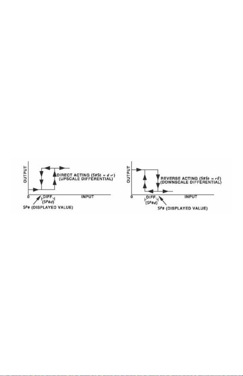
0ut1 Output selection: Select 0n0F, #tP, #PuL, or ProP.
0n0F A setting of 0n0F allows the control to operate in simple on/off
mode. This setting forces the control to turn off at set point, and
on at the set point plus the differential (SP1d). When selected,
the 0ut1 0n0F menu items is followed by #### SP 0d, and
the tunE, Pb, rES, 510L and 510H selections in the Secure
menu are suppressed.
SP1d Set Point On-Off Differential (hysteresis). Set for the
amount of difference between the turn off point and the
turn on point. Select 1 to 9999 (direct acting), or -1 to
-9999 (reverse acting). This value will be negative for
reverse acting set points, and positive for direct acting
outputs. The following drawings shows output behavior
for reverse and direct action. For reverse action note how
the output decreases as the input process variable
increases, e.g. heat power goes to zero as the
temperature increases to set point.
Page 16
##tP Time Proportioning Cycle Time. Select 1tP to 80tP.
1tP A setting of 1tP is recommended for solid state outputs
(SSR or 15VDC).
2tP to 80tP T ime Proportioning Control is adjustable in 1
second steps. Recommended for mechanical outputs
(relays, solenoids, etc.). For best contact life, a time
should be selected as long as possible without causing
the process to wander.
#PuL Pulsed Time Proportioning Output: Select 1PuL to
7PuL. 1PuL = Linear and 7PuL = most nonlinear. Changes
output linearity for use in cooling applications or for
extremely fast response processes. At the center of the
proportional band, a pulse value of 1 provides an output
of one second on and one second off (50% output). A
pulse value of 2 provides an output of one second on and
two seconds off (33% output). Output at center of band
equals one second on, 2
ProP For Current (Code 5) outputs only.
(pulse value-1)
seconds off.
Page 18

The following menu items apply only if your control is equipped with a second set point (last digit of model number is not zero). If your control does
not have a second set point, jump to the tunE menu on the next page.
0ut2 Output selection: Select OnOF, #tP, #PuL, or ProP.
0n0F A setting of 0n0F allows the control to operate in simple on/off
mode. This setting forces the control to turn off at set point, and
on at the set point plus the differential (SP2d). When selected,
the 0ut2/0n0F menu item is followed by #### SP2d, and the
Pb2 selection in the Secondary menu and the S20L and S20H
selections in the Secure menu are suppressed.
SP2d Set Point On-Off Differential (hysteresis). Select 1 to
9999 (direct acting), or -1 to -9999 (reverse acting).
See SP1d on the previous page.
##tP Time Proportioning Cycle Time. Select 1tP to 80tP.
1tP A setting of 1tP is recommended for solid state outputs
(SSR or 15VDC).
2tP to 80tP Time Proportioning Control is adjustable in 1
second steps. Recommended for mechanical outputs
(relays, solenoids, etc.). For best contact, life, a time
should be selected as long as possible without causing
the process to wander.
#PuL Pulsed Time Porpotioning Output: Select 1PuL to 7PuL.
1PuL = Linear and 7PuL = most nonlinear. Changes
output linearity for use in cooling applications or for
extremely fast response processes. At the center of the
proportional band, a pulse value of 1 provides an output
of one second on and one second off (50% output). A
pulse value of 2 provides an output of one second on and
two seconds off (33% output). Output at center of band
equals one second on, 2(pulse value -1) seconds off.
ProP For Current (Code 5) outputs only.
Page 17
Page 19

tunE Tuning Choice: Select SELF, Pid, SL0, nor, or FASt.
SELF The Controller will evaluate the Process and select the PID values to
maintain good control. Active for SP1 only.
LErn Select YES or no
YES Start Lear ning the Process. After the process has
been learned the menu item will revert to no.
no Learning will stay in present mode.
dFAC Damping factor, select 0FF, 1 to 7. Sets the ratio of Rate to
Rate for the SEL tunE mode. 7 = most Rate. Factory set
to 3. For a fast response process the value should be lowered (less Rate). For a slower process the value should be
increased (more Rate).
Pid Manually adjust the PID values. PID control consists of three basic
parameters, Proportional Band (Gain), Reset Time (Integral), and
Rate Time (Derivative).
Pb1 Proportional Band (Bandwidth). Select 1 to 9999°F, °C,
or counts.
Pb2 Proportional Band (Bandwidth). Select 1 to 9999°F, °C,
or counts. Appears only if control is equipped with second
set point and 0ut2 is NOT selected as 0n0F.
Page 18
Page 20

rES Automatic Reset Time. Select 0FF, 0.1 to 99.9 minutes.
Select 0FF to switch to 0FS.
0FS Manual Offset correction Select. Select 0FF, 0.1 to 99.9
percent. Select 0FF to switch to rES.
rtE Rate T ime. Select 0FF, 0.1 to 99.9 minutes. Derivative.
SL0 PID values are preset for a slow response process.
nor PID values are preset for a normal response process.
FASt PID values are preset for a fast response process.
Pid2 Linkage of PID parameters between SP1 and SP2: Select 0n or 0FF.
0n Applies SP1 rES, rtE, Fbnd, and FrtE terms to SP2 for heat/cool
applications
0FF SP2 functions without rES, rtE, Fbnd, and FrtE .
ArUP Anti- Reset Windup Feature: Select 0n or 0FF.
0n When ArUP is 0n the accumulated Reset Offset value will be
cleared to 0% when the process input is not within the Proportional
Band.
0FF When ArUP is 0FF, the accumulated Reset Offset value is retained
in memory when the process input is not within the Proportional
Band.
ArtE Approach Rate Time: Select 0FF, 0.01 to 99.99 minutes. The function
defines the amount of Rate applied when the input is outside of the
Proportional Band. The ArtE time and the rtE time are independent and
have no effect on each other. To increase damping effect and reduce overshoot set the approach rate time for a value greater than the natural rise time
of the process (natural rise time = process value time to set point).
Fint Fuzzy Logic Intensity: Select 0 to 100%. 0% is OFF (disables Fuzzy Logic).
The function defines the amount of impact Fuzzy Logic will have on the
output.
Fbnd Fuzzy Logic Error Band: Select 0 to 4000 °F, °C, or counts. Sets the band
width of the Fuzzy Logic. Set Fbnd equal to PID proportional band (Pb1) for
best results.
Page 19
Page 21

FrtE Fuzzy Logic Rate of Change: Select 0.00 to 99.99 counts/second. For best
initial setting, find the counts/second change of process value near Set Point
1 with output ON 100%. Multiply this value by 3. Set FrtE to this
calculated value.
PEA The Peak feature stores the highest input the control has measured since
the last reset or Power On. At Power On PEA is reset to the present input.
To manually reset the value PEA must be in the lower display. Press the
ENTER key to reset. PEA will be reset and display the present input value.
UAL The Valley feature stores the lowest input the Instrument has measured
since the last reset or Power On. At Power On UAL is reset to the present
input. To manually reset the value UAL must be in the lower display. Press
the ENTER key. UAL will be reset and display the present input value.
Pct0 Percent Output Feature: Select 0n or 0FF.
0n When selected 0n, the HOME lower display will indicate the output
of the controller in percent. An “o” will appear in the right hand side
of the lower display to indicate percent output for SP1. An “ ” will
~
o
appear on the right hand corner of the lower display to represent
percent output for SP2, if the control is so equipped. The display
will alternate between these values.
0FF Percent Output display is disabled.
Page 20
Page 22

1nPC Input Correction: Select -500 to 0 to 500 °F, °C, or counts. This feature
allows the input value to be changed to agree with an external reference or
to compensate for sensor error. Note: 1nPC is reset to zero when the input
type is changed, or when decimal position is changed. Factory default is 0.
FiLt Digital Filter: Select 0FF, 1 to 99. In some cases the time constant of the
sensor, or noise, could cause the display to jump enough to be unreadable.
A setting of 2 is usually sufficient filtering (2 represents approximately a 1
second time constant). When the 0.1 degree resolution is selected this
should be increased to 4. If this value is set too high, controllability will
suffer.
Page 21
Page 23

LPbr Loop Break Protection: Select 0FF, 1 to 9999 seconds. If, during operation,
the output is minimum (0%) or maximum (100%), and the input moves less
than 5°F (3°C) or 5 counts over the time set for LPbr, the L00P bAd message will appear. This condition can also be routed to an Alarm Condition if
alarms are present and turned On (see ALbr in the Secure Menu). The loop
break error can be reset by pressing the ENTER key when at the LPbr
menu item. The INDEX & ENTER keys may also be used.
L0rE (Option C2, C4, Serial Communications) Local / Remote Status: Select
L0C or rE. Does not affect other instruments on daisy chain.
L0C The host computer is advised that remote write commands will be
rejected. Any write commands sent to this control will be rejected.
All read commands are accepted.
rE The host computer is allowed to send write commands. If the
control is not addressed within the time set in nAt (No Activity
Timer in the Secure Menu) the CHEC LorE error message will be
displayed.
Addr (Option C4, C2 Serial Communications) Control
Address: Set from 1 to 3FF (Options C4 and C2) This number
(hexadecimal, base 16) must match the address number used
by the host computer.
Not settable in this menu. To change this parameter, see Addr in
the Secure Menu.
SECURE MENU
Hold UP ARROW & ENTER for 5 Seconds. Press INDEX to advance
to the next menu item. Press UP ARROW or DOWN ARROW to change
the value in the display. Press ENTER to retain the value.
OUTPUTS ARE DISABLED (TURNED OFF) WHILE CONTROL IS IN
SECURE MENU.
SECr Security Code: See the Security Level Selection and the Password
Table in this manual, in order to enter the correct password.
1nP Input Type: Select one of the following. Refer to the Wiring section
for the proper wiring.
Page 22
Page 24

J-1C Type “J” Thermocouple
CA Type “K” Thermocouple
E- Type “E” Thermocouple
t- Type “T” Thermocouple
L- Type “L” Thermocouple
n- Type “N” Thermocouple
r-13 Type “R” Thermocouple
S-10 Type “S” Thermocouple
b- Type “B” Thermocouple
C- Type “C” Thermocouple
P392 100 ohm Platinum (NIST 0.00392 / /°C)
n120 120 ohm Nickel
P385 100 ohm Platinum (IEC/DIN 0.00385 / /°C)
1P38 1000 ohm Platinum (IEC/DIN 0.00385 / /°C)
Curr DC Current Input 0.0 to 20.0 or 4.0 to 20.0 mA.
UoLt DC Voltage Input 0.0 to 10.0 or 1.0 to 10.0 volts.
diFF DC Voltage Input -10 to +10 mV.
- - - - Reserved
0SUP Zero Suppression: Select On or OFF. Only with Current and Voltage
input types.
0FF The input range will start at 0 (zero) Input.
0n The input range will start at 4.00 mA or 1.00 V.
Unit F, C or nonE.
F °F descriptor is On and temperature inputs will be displayed in
actual degrees Fahrenheit.
C °C descriptor is On and temperature inputs will be displayed in
actual degrees Celsius.
nonE °F and °C descriptors will be Off. This is only available with Current
and Voltage Inputs.
dPt Decimal Point Positioning: Select 0, 0.0, 0.00, 0.000, or .0000. On
temperature type inputs a change here will alter the Process Value, SP1,
SP2, ALLo, ALHi, and InPC. For current and voltage Inputs all Menu Items
related to the Input will be affected.
0 No decimal Point is selected. This is available for all Input Types.
0.0 One decimal place is available for Type J, K, E, T, L, RTD’s, Current
and Voltage Inputs.
0.00 Two decimal places is only available for Current and Voltage Inputs.
0.000 Three decimal places is only available for Current and Voltage
inputs.
.0000 Four decimal places is only available for Current and Voltage inputs.
Page 23
Page 25

1nPt Input Fault T imer: Select 0FF, 0.1 to 540.0 minutes. Whenever an Input is
out of range (UFL or 0FL displayed), shorted, or open, the timer will start.
When the time has elapsed, the controller will revert to the output condition
selected by 1nPb below. If 0FF is selected, the Input Fault Timer will not be
recognized (time = infinite).
SEnC Sensor Rate of Change: Select 0FF, 1 to 4000 °F, °C, or counts per 1
second period. This value is usually set to be slightly greater than the fastest
process response expected during a 1 second period, but measured for at
least 2 seconds. If the process is faster than this setting, the SEnC bAd
error message will appear. The outputs will then be turned off. This function
can be used to detect a runaway condition, or speed up detection of an
open thermocouple. Use the INDEX & ENTER keys to reset.
SCAL Scale Low: Select 100 to 11998 counts below SCAH. The total span
between SCAL and SCAH must be within 11998 counts. Maximum setting
range is -1999 to +9999 counts. For Current and V oltage inputs, this will set
the low range end. Value not adjustable for Thermocouple and RTD ranges.
SCAH Scale High: Select 100 to 11998 counts above SCAL. The total span
between SCAL and SCAH must be within 11998 counts. Maximum setting
range is -1999 to +9999 counts. For Current and V oltage inputs, this will set
the high range end. Value not adjustable for Thermocouple and RTD ranges.
SPL Set Point Low: Select from the lowest input range value to SPH value. This
will set the minimum SP1 or SP2 value that can be entered. The values for
SP1 or SP2 will stop moving when this value is reached.
SPH Set Point High: Select from the highest input range value to SPL value. This
will set the maximum SP1 or SP2 value that can be entered. The values for
SP1 or SP2 will stop moving when this value is reached.
SP10 Set Point 1 Output Select: Select 0utA or 0utb.
0utA Set Point 1 is routed through Output A, Set Point 2 (if equipped) is
routed through Output B.
0utb Set Point 1 is routed through Output B, Set Point 2 (if equipped) is
routed through Output A.
Page 24
Page 26

S St Set Point 1 state : Select dir or rE.
dir Direct Action. As the input increases the output will increase. Most
commonly used in cooling processes.
rE Reverse Action. As the input increases the output will decrease.
Most commonly used in heating processes.
If 0ut1 (Page 21) is set for ##tP, #PUL, or ProP, then S10L and S10L
appear. If 0ut1 is set for 0n0F, then skip S1rE.
S10L Set Point Output Low Limit. Select 0 to 100% but not greater than S10H.
This item limits the lowest output value. This is useful for adding a bias to
the process when needed. Factory set to 0 for output codes 1, 2, 3, 4,
and 8. Factory set to 20 for output code 5 (20% output equals 4 mA
output).
S10H Set Point 1 Output High Limit. Select 0 to 100% but not less than S10L
for output codes 1, 2, 3, 4, or 8. Select 0 to 102% but not less than
S10L for output code 5. This item allows setting the maximum output
limit. This is useful with processes that are over powered. Adjustment to
102% allows seeting current output to force a full on condition for output
devices which do not have bias adjustments. Factory set to 100 for all
output codes.
If 0ut1 is set for ##tP, #PUL, or ProP, then skip to S1LP below.
If 0ut1 is set to 0n0F (in Secondary Menu), then the next three menu items can
make the SP1 and SP1d settings act like a high or low alarm set point. See the
information on alarm settings and the cautions and warnings that apply to them on
Pages 30-31.
Note that when Set Point 1 Power Interrupt, S1P, is 0n, and Set Point 1 Reset,
S1rE, is programmed to HoLd, the SP1 output will automatically reset upon a
power failure and subsequent restoration, if the process is below SP1.
S1rE Set Point 1 Reset. Select 0n0F or HoLd.
0n0F Output will automatically reset when process passes back
through SP1d.
HoLd Manual Reset. Reset by simultaneously pressing the
INDEX & DOWN ARROW keys for 3 seconds.
Page 25
Page 27

S1Pi Set Point 1 Power Interrupt. Select 0n or 0FF.
0n Alarm Power Interrupt is 0n. Output will automatically
reset on power-up if no alarm condition exists.
0FF Alarm Power Interrupt is 0FF. Output will be in the
alarm condition on power-up regardless of condition of
process.
S1iH Set Point 1 Inhibit: Select 0n or 0FF.
0n Alarm Inhibit is On. Alarm action is suspended until the
process value first enters a non-alarm condition.
0FF Alarm Inhibit is OFF.
S1LP Set Point Lamp: Select 0onor 0oFF.
0on Lamp ON when Output is ON.
0oFF Lamp OFF when Output is ON.
If your control is not equipped with Set Point 2, then proceed to the
alarm section (next page).
S2t Set Point 2 type: Select Ab or dE.
AbS Absolute SP2. SP2 is independent of SP1, and may be
set anywhere between the limits of SPL and SPH.
dE Deviation SP2.SP2 is set as a deviation from SP1, and
allows SP2 to retain its relationship with
is changed (SP2 tracks SP1).
S2St Set Point 2 State: Select dir or rE.
dir Direct Action. As the input increases the output will
increase. Most commonly used in cooling processes.
rE Reverse Action. As the input increases the output will
decrease. Most commonly used in heating processes.
SP1 when SP1
If 0ut2 is set for ##tP, #PUL, or ProP, then S20L and S20H appear. If 0ut2
is set for 0n0F, then skip S20L and S20H.
S20L Set Point Output Low Limit: Select 0 to 100% but not greater than
S20H. This item limits the lowest output value. This is useful for
adding a bias to the process when needed. Factory set to 0 for
output codes 1,2, 3, 4, and 8. Factory set to 20 for output code 5
(20% output equals 4 mA output).
S20H Set Point 2 Output High Limit: Select 0 to 100% but not less than
S20L for output codes 1, 2, 3, 4, or 8. Select 0 to 102% but not
less than S20L for output code 5. This item allows setting the
maximum output limit. This is useful with processes that are over
powered. Adjustment to 102% allows setting current output to
Page 26
Page 28

force a full on condition for output devices which do not have bias
adjustments. Factory set to 100 for all output codes.
If 0ut2 is set to 0n0F (in the Secondary Menu), then the next three menu
items can make the SP2 and SP2d settings act like a high or low alarm set
point. See the information on alarm settings and the cautions and warnings
that apply to them on the next pages.
Note that when Set Point 2 Power Interrupt , S2Pi is On, and Set Point
2 Reset, S2rE, is programmed to Hold, the SP2 output will automatically
reset upon a power failure and subsequent restoration, if the process is
below SP2.
S2rE Set Point 2 Reset. Select 0n0F or Hold.
0n0F Output will automatically reset when process passes
back through SP2d.
HoLd Manual Reset. Reset (acknowledge) by simultaneously
pressing the INDEX & DOWN ARROW keys
for 3 seconds.
S2Pi Set Point 2 Power Interrupt. Select On or OFF.
0n Alarm Power Interrupt is On. Output will automatically
reset on power-up if no alarm condition exists.
0FF Alarm Power Interrupt is OFF. Output will be in the
alarm condition on power-up regardless of condition of
process.
S2iH Set Point 2 Inhibit: Select On or OFF.
0n Alarm Inhibit is On. Alarm action is suspended until the
process value fi rst enters a non-alarm condition.
0FF Alarm Inhibit is OFF.
S2LP Set Point 2 Lamp: Select O on or OoFF.
0on Lamp ON when Output is ON.
0oFF Lamp OFF when Output is ON.
ALARM TYPE AND ACTION (if alarm function is present)
Caution: In any critical application where failure could
cause expensive product loss or endanger personal safety,
a redundant limit controller is required.
When setting an alarm value for an absolute alarm (A1t = AbS), simply set
the value at which the alarm is to occur.
When setting the alarm value for a deviation alarm (A1t = dE), set the difference
in value from the Set Point desired. For example if a low alarm is
Page 27
Page 29
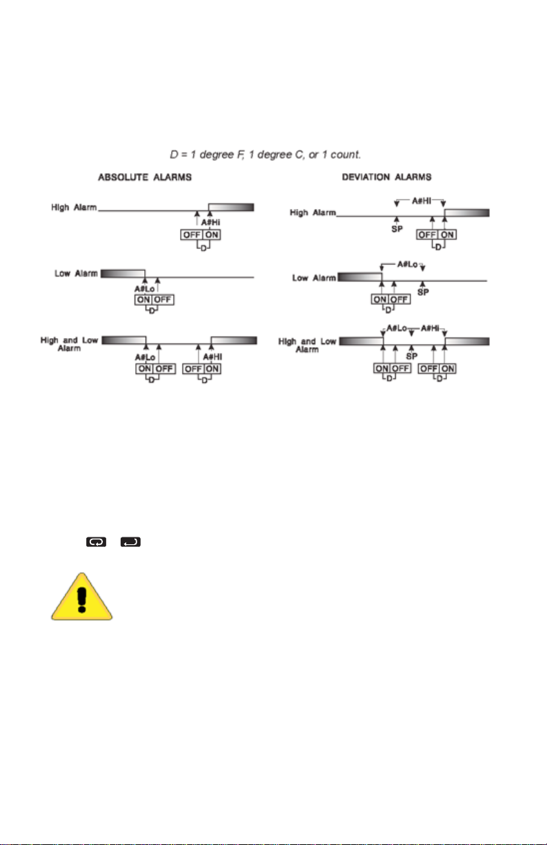
required to be 5 degrees below the Set Point, then set A1Lo to -5. If a high
alarm is required 20 degrees above the Set Point, then set A1Hi to +20. If
the Set Point is changed, the alarm will continue to hold the same relationship
as originally set.
The diagram below shows the action and reset functions for both absolute
and deviation alarms.
Note that when Alarm Power Interrupt, A1Pi, is programmed ON and Alarm
Reset, A1rE, is programmed for Hold, the alarm will automatically reset
upon a power failure and subsequent restoration if no alarm condition is
present.
If Alarm Inhibit, A1iH, is selected ON, an alarm condition is suspended
upon power up until the process value passes through the alarm set point
once. Alarm inhibit can be restored as if a power up took place by pressing
both the INDEX and ENTER keys for 3 seconds.
WARNING: IF INHIBIT IS ON AND A POWER FAILURE OCCURS
DURING A HIGH ALARM, RESTORATION OF POWER WILL NOT
CAUSE THE ALARM TO OCCUR IF THE PROCESS VALUE
DOES NOT FIRST DROP BELOW THE HIGH ALARM SETTING.
DO NOT USE THE ALARM INHIBIT FEATURE IF A HAZARD IS
CREATED BY THIS ACTION. BE SURE TO TEST ALL COMBINA
TIONS OF HIGH AND LOW ALARM INHIBIT ACTIONS BEFORE
PLACING CONTROL INTO OPERATION.
Page 28
Page 30

The following menu items apply only to the alarm.
AL1 Alarm 1 function: Select 0FF, Lo, Hi, or HiLo.
0FF Alarm 1 is disabled. No Alarm 1 menu items appear in the
Secondary or Secure menus.
Lo Low Alarm Only. A1Lo appears in the Secondary
Menu.
Hi High Alarm Only. A1Hi appears in the Secondary Menu.
HiLo High and Low Alarms. Both A1Lo and A1Hi appear in the
Secondary Menu, and share the same Alarm 1 Relay output.
If AL1 is set to 0FF and the control is not equipped with options, the Secure Menu
ends here. If AL1 is set to 0FF and the control is equipped with options, proceed to
Addr below.
A1t Alarm 1 Type: Select AbS or dE
AbS Absolute Alarm that may be set anywhere within the values of SCAL
and SCAH and is independent of SP1.
dE Deviation Alarm that may be set as an offset from SP1. As SP1 is
changed the Alarm Point will track with SP1.
A1rE Alarm 1 Reset: Select 0n0F or HoLd.
0n0F Automatic Reset.
HoLd Manual Reset. Reset (acknowledge) by simultaneously pressing the
INDEX & DOWN ARROW keys for 3 seconds.
A1Pi Alarm 1 Power Interrupt: Select 0n or 0FF.
0n Alarm Power Interrupt is 0n.
0FF Alarm Power Interrupt is 0FF.
A1iH Alarm 1 Inhibit: Select 0n or 0FF.
0n Alarm Inhibit is 0n. Alarm action is suspended until the process
value first enters a non-alarm condition.
0FF Alarm Inhibit is 0FF.
A1St Alarm 1 Output State: Select CL0S or 0PEn.
CL0S Closes Contacts at Alarm Set Point.
0PEn Opens Contacts at Alarm Set Point.
Page 29
Page 31

A1LP Alarm 1 Lamp: Select 0on or 0oFF.
0on Alarm Lamp is ON when alarm contact is closed.
0oFF Alarm Lamp is OFF when alarm contact is closed.
A1Lb Alarm 1 Loop Break. Select 0n or 0FF.
0n Loop Break Condition will cause an Alarm Condition.
0FF Loop Break will not affect the Alarm Condition.
Addr (Option C2, C4, Serial Communications) Control Address: Set from
to
3FF
for Options C4 and C2. This number (hexadecimal, base 16)
must match the address number used by the host computer. Power to
instrument must be turned off and on before change takes effect (see Page
14).
bAUd (Option C2, C4, Serial Communications) Communication Baud Rate:
Select
300,1200, 2400, 4800, 9600
(baud),
19.2
or
28.8
(kbaud).
This number must match the baud rate used by the host computer. Power
to instrument must be turned off and on before change takes effect (see
Page 14).
nAt (Option C2, C4, Serial Communications) No Activity Timer:
Select
1- 99 Maximum time between host computer accesses. If timer counts
0FF No Activity Timer function is disabled.
Stor (Option C2, C4, Serial Communications) Store to EEPROM:
Select
YES Menu Item changes made through the Serial Communications are
0FF
or 1 to 99minutes.
to 0,
CHEC LorE
YES
or no. (See additional information on page 18).
will be displayed.
stored directly to the EEPROM.
no Menu Item changes made through the Serial Communications are
stored in RAM.
1
Page 30
Page 32
ERROR MESSAGES
Any error message may be cleared by using the ‘Global Reset’ by pressing
and holding the INDEX & ENTER keys for five seconds.
DISPLAY MEANING
ArEA
(Alternates
with PV)
ArEA
This message
appears if the
ambient temperature
of the control
approaches the ends
of tolerance.
This message
appears
if the ambient
temperature of the
control is out of
range
or RJC sensor is
broken.
SP
OUTPUTS
Set point
outputs
active.
Alarm active.
Set point
outputs
active.
Alarm active.
ACTION
REQUIRED
Correct the ambient temperature
conditions. Ventilate the
area of the cabinet or
check for clogged filters.
If internal temperature
sensor is broken
(RJC located in terminal 2),
return to service.
Correct the ambient temperature
conditions. Ventilate the area of
the cabinet or
check for clogged filters.
If internal temperature
sensor is broken,
return for service.
Page 31
Page 33

ERROR MESSAGES
Any error message may be cleared by using the ‘Global Reset’ by pressing
and holding the INDEX & ENTER keys for fi ve seconds.
DISPLAY
UFL
or
0FL
bAd
1nP
0PEn
1nP
L00P
bAd
SEnC
bAd
MEANING SP OUTPUTS ACTION REQUIRED
Underflow or Overflow:
Process value has
exceeded input range
ends.
UFL or 0FL will
sequence to display
one of these messages
if the InPt is set for a
time value.
For RTD inputs RTD is
open or shorted. For
THERMOCOUPLE
inputs thermocouple
is open.
The sensor may be
defective, heater fuse
open, heater open, or
the final power output
device is bad.
Sensor Rate of
Change exceeded
the programmed
limits set for
SEnC.
Set point outputs
active.
Alarm active.
Set point outputs
inactive.
Alarm active.
Set point outputs
inactive.
Alarm active.
Set point outputs
inactive.
Alarm active.
May be normal if Input signals
go above or below range ends.
If not the case, check sensor,
input wiring and correct.
1nPt (input fault timer)
When
has been set for a time, the
outputs will be turned off after
the set time. Setting the time
0FF causes the outputs to
to
remain active, however
0FL will still be displayed.
Correct or replace sensor.
Clear with ‘Global Reset’.
Correct or replace sensor, or
any element in the control loop
that may have failed.
Correct the problem.
Check for the cause of the
error. The value setting may
be too slow for the process, or
the sensor is intermittent.
Correct the problem.
UFL or
CHEC
CAL
Page 32
Check calibration
appears as an
alternating message
if the instrument cali-
bration nears tolerance
edges.
Check calibration
appears as a flashing
message if the instru-
ment calibration
exceeds specification.
Set point outputs
inactive.
Alarm active.
Set point outputs
inactive.
Alarm active.
Remove the instrument for
service and / or recalibration.
Remove the instrument for
service and / or recalibration.
Page 34

ERROR MESSAGES
Any error message may be cleared by using the ‘Global Reset’ by pressing
and holding the INDEX & ENTER keys for fi ve seconds.
DISPLAY MEANING SP OUTPUTS
No display
lighted
FA1L
tESt
CHEC
SP1,
CHEC
SP2,
CHEC
1SP, ...,
CHEC
16SP
CHEC
SPL
or
CHEC
SPH
CHEC
rSPt
Display is blank.
Instrument is not getting
power, or the supply volt-
age is too low.
Fail test appears upon
power up if the internal
diagnostics detect a fail-
ure. This message may
occur during operation if
a failure is detected.
Displays flash.
Fail test may also occur
due to an EEPROM error.
This message will
appear upon power up
if SP1, SP2, #SP1, or
SP is set outside of
##
the SPL or SPH values.
This message appears
at power up if
values are programmed
outside the input range
SPL or SPH
ends.
This message appears
if the analog remote
set point signal is out
of range.
Set point outputs
inactive.
Alarm inactive
Set point outputs
inactive.
Alarm inactive
Set point outputs
inactive.
Alarm active
Set point outputs
inactive.
Alarm active
Set point outputs
inactive.
Alarm active
ACTION REQUIRED
Check that the power
supply is on, measure
supply voltage, check
that the external fuses
are good.
The display alternates
between
default settings. Recheck
controller programming.
FA1L tESt and
one of the following
messages:
FACt dFLt: Memory
may be corrupted.
Restore to the factory
rEt FACt:
Unrecoverable error.
Return to service.
Correct the SP1, etc.
or adjust the SPL or
SPH values by
programming
new values.
Correct the SPL or SPH
values by
programming
new values.
The control will revert to
SP1. Correction of the
analog signal or turning
rSPt clears the
off the
error message.
CHEC
LorE
This message
appears if the
Serial Communications
has timed out.
Set point outputs
inactive.
Alarm active
Change the LorE to
L0C. Restore the
communications line
and switch
LorE back
rE.
to
Page 33
Page 35

SPECIFICATIONS
Selectable Inputs: Thermocouple, RTD, DC Voltage, or DC Current selectable.
Input Impedance:
Sensor Break Protection: De-energizes control output to protect system after customer set
time. (See InPt in Secure Menu.)
Set Point Range: Selectable (See Input Ranges Page 43).
Display: Two 4 digit, 7 segment 0.3” high LEDs.
Control Action: Reverse (usually heating), Direct (usually cooling) selectable.
Proportional Band: 1 to 9999 °F, °C, or counts.
Reset Time (Integral): Off or 0.1 to 99.9 minutes.
Rate Time (Derivative): Off or 0.01 to 99.99 minutes.
Cycle Rate: 1 to 80 seconds.
On - Off Differential: Adjustable 1° F, 1° C, or 1 count to full scale in 1° F, 1° C, or 1 count
steps.
Alarm On - Off Differential: 1° F, 1° C, or 1 count.
Fuzzy Percent: 0 to 100%.
Fuzzy Rate: Off or 0.01 to 99.99 counts per second.
Fuzzy Band: Off or 1 to 4000 °F, °C, or counts.
Accuracy: ±0.25% of span, ±1 least signifi cant digit.
Resolution: 1 degree or 0.1 degree, selectable.
Line Voltage Stability: ±0.05% over the supply voltage range.
Temperature Stability: 4µV/°C (2.3 µV/°F) typical, 8 µV/°C (4.5 µV°F)
maximum (100 ppm / °C typical, 200 ppm / °C maximum).
Common Mode Rejection: 140 db minimum at 60 Hz.
Normal Mode Rejection: 65 db typical, 60 db at 60 Hz.
Isolation:
Supply Voltage: 100 to 240 Vac, nominal, +10 -15%, 50 to 400 Hz. single phase; 132 to 240
Vdc, nominal, +10 -20%.
Supply Voltage (Option 9502): 12 to 24 Vdc, Vac 40-400 Hz, ±20%.
Power Consumption: 5VA maximum.
Operating Temperature: -10 to +55 °C (+14 to 131 °F).
Storage Temperature: -40 to +80 °C (-40 to 176 °F).
Humidity Conditions: 0 to 90% up to 40°C non-condensing, 10 to 50% at 55°C
non-condensing.
Memory Backup: Nonvolatile memory. No batteries required.
Control Output Ratings:
Panel Cutout: 45 mm x 45 mm (1.775” x 1.775
Depth Behind Mounting Surface: 121.6 mm (4.79”) maximum.
Weight: 220 g (8 oz).
Agency Approvals: UL, C-UL E83725
Front Panel Rating: IP66, (UL Type 4X).
Thermocouple = 3 megohms minimum. RTD current = 200 µA.
Current = 10 ohms. Voltage = 5000 ohms.
Relay and SSR outputs: 1500 Vac to all other inputs and outputs.
SP1 and SP2 Current output: 500 Vac to all other inputs and outputs but not isolated
from each other.
SP1 and SP2 Switched Voltage output: 500 Vac to all other inputs and outputs, but
not isolated from each other.
Process Output (934, 936): 500 VAC to all other inputs and outputs.
SSR: 2.0 A combined outputs A & B @ 240 VAC at 25°C (77°F).
Derates to 1.0 A @ 55°C (130°F).
Relay: SPST, 3 A @ 240 VAC resistive; 1.5A @ 240 VAC inductive; Pilot
duty rating 240 VA, 2 A @ 120 VAC or 1 A 240 VAC.
Alarm Relay: SPST, 3 A @ 240 VAC resistive; 1/10 HP @ 120 VAC.
Current (isolated): 0 to 20 mA across 600 ohms maximum.
Switched Voltage (isolated): 15 VDC @ 20 mA.
DC SSR: 1.75 A @ 32 Vdc maximum.
”).
Page 34
Page 36

-PV1 Analog Retransmission of PV/SV (Programmable)
Output: 0 to 20 mADC into 600 Ohms, maximum.
Isolation: 500 VAC.
Scale: Programmable from 100 to 11998 counts, depending on PV range
selected.
-PV2 Analog Retransmission of PV/SV (Programmable)
Output: 0 to 10 VDC @ 20 mA maximum.
Isolation: 500 VAC.
Scale: Programmable from 100 to 11998 counts, depending on PV range
selected.
-C2 RS-485 Series Communications
Port Compliance: EIA-485.
Isolation: 500 VAC.
Protocol: Lovelinks™ II.
Address Range: 001H or 3FFH.
Baud Rates: 300, 1200, 2400, 4800, 9600, 19.2k, 28.8k, 57.6k,
Mode: Half duplex.
Character: 8 bits, 1 start, 1 stop, no parity.
1
Number of units on line/ports
: 32.
Cable Lengths1: 6,000 ft (1,828 m).
Termination: 120 Ohms, balanced.
-C4 RS-232 Series Communications
Port Compliance: RS-232C.
Isolation: 500 VAC.
Protocol: Lovelinks™ II.
Address Range: 001H or 3FFH.
Baud Rates: 300, 1200, 2400, 4800, 9600, 19.2k, 28.8k, 57.6k.
Mode: Half duplex.
Character: 8 bits, 1 start, 1 stop, no parity.
Number of units on line/ports: 1.
Cable Lengths1: 25 ft (7.6 m).
Page 35
Page 37

Termination: 120 Ohms, balanced.
1
Number can be increased through use of a repeater such as the Mother
Node™. Consult factory for details.
INPUT RANGES
INPUT TYPE RANGE °F RANGE °C
Type J or L1Thermocouple -100 to +1607 -73 to +871
Type K1 Thermocouple -200 to +2500 -129 to +1371
Type T1 Thermocouple -350 to +750 -212 to +398
Type E1 Thermocouple -100 to +1800 -73 to +982
Type R Thermocouple 0 to 3200 -17 to +1760
Type S Thermocouple 0 to 3200 -17 to +1760
Type B Thermocouple +75 to +3308 +24 to +1820
Type C Thermocouple 0 to 4208 -17 to +2320
Type N1 Thermocouple -100 to +2372 -73 to +1300
100 Ω Plt. 0.00385 DIN1RTD -328 to 1607 -200 to +875
100 Ω Plt. 0.00392 NIST1RTD -328 to 1607 -200 to +875
120 Ω Nickel 0.00628 US1 RTD -112 to +608 -80 to +320
1000 Ω Plt. 0.00385 DIN1RTD -328 to +1607 -200 to +875
Current/Voltage/∆Voltage
2
Scalable Units from -1999 to +9999
1
These Input Types can be set for 0.1°display. If temperature goes above
999.9°or less than -199.9°the display will return to whole degree resolution.
2
The 0 to 20 mADC, 4 to 20 mADC, 0 to 10 VDC, 2 to 10 VDC, and -10 to +10
mVDC inputs are fully scalable from a minimum of 100 counts span placed any
where within the within the range of -1999 to +9999. Decimal point position is
adjustable from the zero place (9999), tenths (999.9), hundredths (99.99), thousandths (9.999), or ten thousandths (.9999).
Page 36Page 36
Page 38

WARRANTY/DISCLAIMER
OMEGA ENGINEERING, INC. warrants this unit to be free of defects in materials and workmanship for a
period of 13 months from date of purchase. OMEGA’s WARRANTY adds an additional one (1) month grace
period to the normal one (1) year product warranty to cover handling and shipping time. This ensures
that OMEGA’s customers receive maximum coverage on each product.
If the unit malfunctions, it must be returned to the factory for evaluation. OMEGA’s Customer Service
Department will issue an Authorized Return (AR) number immediately upon phone or written request.
Upon examination by OMEGA, if the unit is found to be defective, it will be repaired or replaced at no
charge. OMEGA’s WARRANTY does not apply to defects resulting from any action of the purchaser,
including but not limited to mishandling, improper interfacing, operation outside of design limits,
improper repair, or unauthorized modification. This WARRANTY is VOID if the unit shows evidence of
having been tampered with or shows evidence of having been damaged as a result of excessive corrosion;
or current, heat, moisture or vibration; improper specification; misapplication; misuse or other operating
conditions outside of OMEGA’s control. Components in which wear is not warranted, include but are not
limited to contact points, fuses, and triacs.
OMEGA is pleased to offer suggestions on the use of its various products. However,
OMEGA neither assumes responsibility for any omissions or errors nor assumes liability for
any damages that result from the use of its products in accordance with information provided
by OMEGA, either verbal or written. OMEGA warrants only that the parts manufactured by the
company will be as specified and free of defects. OMEGA MAKES NO OTHER WARRANTIES OR
REPRESENTATIONS OF ANY KIND WHATSOEVER, EXPRESSED OR IMPLIED, EXCEPT THAT OF
TITLE, AND ALL IMPLIED WARRANTIES INCLUDING ANY WARRANTY OF MERCHANTABILITY
AND FITNESS FOR A PARTICULAR PURPOSE ARE HEREBY DISCLAIMED. LIMITATION OF
LIABILITY: The remedies of purchaser set forth herein are exclusive, and the total liability of
OMEGA with respect to this order, whether based on contract, warranty, negligence,
indemnification, strict liability or otherwise, shall not exceed the purchase price of the
component upon which liability is based. In no event shall OMEGA be liable for
consequential, incidental or special damages.
CONDITIONS: Equipment sold by OMEGA is not intended to be used, nor shall it be used: (1) as a “Basic
Component” under 10 CFR 21 (NRC), used in or with any nuclear installation or activity; or (2) in medical
applications or used on humans. Should any Product(s) be used in or with any nuclear installation or
activity, medical application, used on humans, or misused in any way, OMEGA assumes no responsibility
as set forth in our basic WARRANTY/DISCLAIMER language, and, additionally, purchaser will indemnify
OMEGA and hold OMEGA harmless from any liability or damage whatsoever arising out of the use of the
Product(s) in such a manner.
RETURN REQUESTS/INQUIRIES
Direct all warranty and repair requests/inquiries to the OMEGA Customer Service Department. BEFORE
RETURNING ANY PRODUCT(S) TO OMEGA, PURCHASER MUST OBTAIN AN AUTHORIZED RETURN (AR)
NUMBER FROM OMEGA’S CUSTOMER SERVICE DEPARTMENT (IN ORDER TO AVOID PROCESSING
DELAYS). The assigned AR number should then be marked on the outside of the return package and on any
correspondence.
The purchaser is responsible for shipping charges, freight, insurance and proper packaging to prevent
breakage in transit.
FOR WARRANTY RETURNS, please have the
following information available BEFORE contacting
OMEGA:
1. Purchase Order number under which the product
was PURCHASED,
2. Model and serial number of the product under
warranty, and
3. Repair instructions and/or specific problems
relative to the product.
OMEGA’s policy is to make running changes, not model changes, whenever an improvement is possible. This affords our
customers the latest in technology and engineering.
OMEGA is a registered trademark of OMEGA ENGINEERING, INC.
© Copyright 2017 OMEGA ENGINEERING, INC. All rights reserved. This document may not be copied, photocopied,
reproduced, translated, or reduced to any electronic medium or machine-readable form, in whole or in part, without the prior
written consent of OMEGA ENGINEERING, INC.
FOR NON-WARRANTY REPAIRS, consult
OMEGA for current repair charges. Have
the following information available BEFORE
contacting OMEGA:
1. Purchase Order number to cover the COST
of the repair,
2. Model and serial number of the product, and
3. Repair instructions and/or specific problems
relative to the product.
Page 39

Where Do I Find Everything I Need for
Process Measurement and Control?
OMEGA…Of Course!
Shop online at omega.com
TEMPERATURE
MU
Thermocouple, RTD & Thermistor Probes, Connectors,
Panels & Assemblies
MU
Wire: Thermocouple, RTD & Thermistor
MU
Calibrators & Ice Point References
MU
Recorders, Controllers & Process Monitors
MU
Infrared Pyrometers
PRESSURE, STRAIN AND FORCE
MU
Transducers & Strain Gages
MU
Load Cells & Pressure Gages
MU
Displacement Transducers
MU
Instrumentation & Accessories
FLOW/LEVEL
MU
Rotameters, Gas Mass Flowmeters & Flow Computers
MU
Air Velocity Indicators
MU
Turbine/Paddlewheel Systems
MU
Totalizers & Batch Controllers
pH/CONDUCTIVITY
MU
pH Electrodes, Testers & Accessories
MU
Benchtop/Laboratory Meters
MU
Controllers, Calibrators, Simulators & Pumps
MU
Industrial pH & Conductivity Equipment
DATA ACQUISITION
MU
Communications-Based Acquisition Systems
MU
Data Logging Systems
MU
Wireless Sensors, Transmitters, & Receivers
MU
Signal Conditioners
MU
Data Acquisition Software
HEATERS
MU
Heating Cable
MU
Cartridge & Strip Heaters
MU
Immersion & Band Heaters
MU
Flexible Heaters
MU
Laboratory Heaters
ENVIRONMENTAL
MONITORING AND CONTROL
MU
Metering & Control Instrumentation
MU
Refractometers
MU
Pumps & Tubing
MU
Air, Soil & Water Monitors
MU
Industrial Water & Wastewater Treatment
MU
pH, Conductivity & Dissolved Oxygen Instruments
M4441/1017
 Loading...