

Page 1
FM
APPROVED
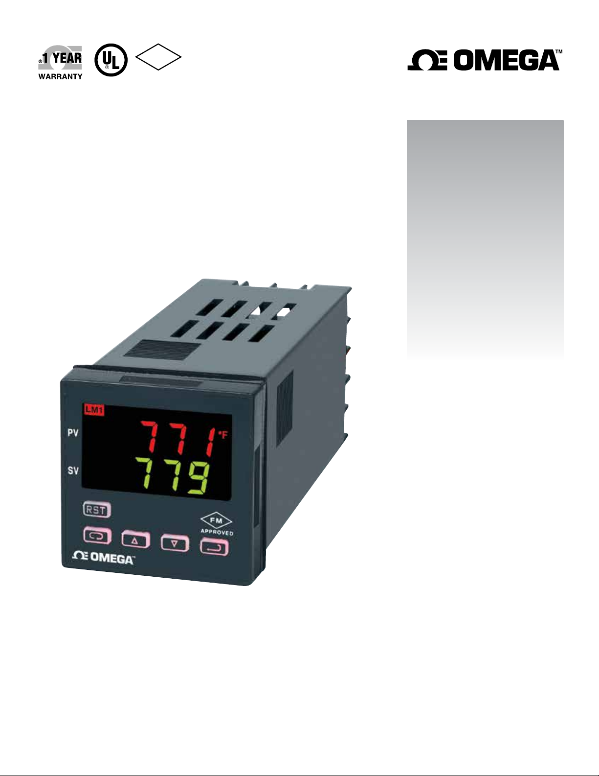
User’s Guide
Shop online at
omega.com
e-mail: [email protected]
For latest product manuals:
www.omegamanual.info
CN7400
1
⁄16 DIN Temperature/
Process Limit Controllers
Page 2

omega.com [email protected]
Servicing North America:
U.S.A. Omega Engineering, Inc.
Headquarters: Toll-Free: 1-800-826-6342 (USA & Canada only)
Customer Service: 1-800-622-2378 (USA & Canada only)
Engineering Service: 1-800-872-9436 (USA & Canada only)
Tel: (203) 359-1660 Fax: (203) 359-7700
e-mail: [email protected]
For Other Locations Visit omega.com/worldwide
The information contained in this document is believed to be correct, but OMEGA accepts no liability for any errors it contains, and reserves
the right to alter specifications without notice.
Page 3
CONTENTS
MODEL IDENTIFICATION.....................................................................2
GETTING STARTED.............................................................................3
INSTALLATION.....................................................................................4
WIRING................................................................................................5
Wiring for 4 to 20mA Transmitter inputs.....................................6
Wiring for Optional Inputs and Outputs......................................6
FRONT PANEL KEY FUNCTIONS........................................................8
NOTATION CONVENTIONS FOR THE MENUS..................................10
THE HOME DISPLAY..........................................................................11
OPERATION AND PROGRAMMING OF OPTIONS.............................11
PRIMARY MENU................................................................................13
SECONDARY MENU..........................................................................13
SECURE MENU.................................................................................15
DIAGNOSTIC ERROR MESSAGES....................................................20
SPECIFICATIONS...............................................................................22
DIMENSIONS.....................................................................................24
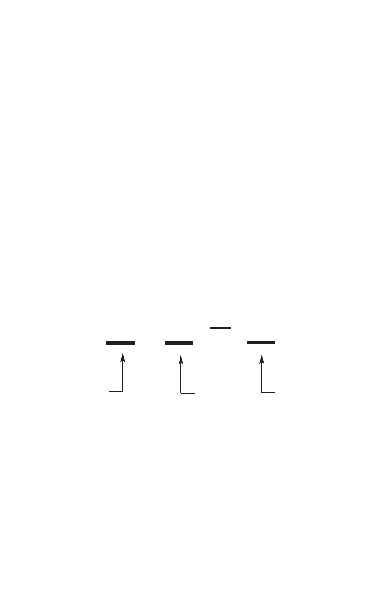
MODEL IDENTIFICATION
CN74
Output A
3 = N.O. Relay
Output B
0 = None
4 = N.C. Relay
Options
PV1 = 0-20 mA
Options:
PV1 Analog Retransmission of Process Variable, 4 to 20 mAdc.
LV 12 - 24 Vdc/Vac 50 - 400 Hz power supply (control operates on
low voltage equipment).
Page 2 of 25
Page 4

GETTING STARTED
1. Install the control as described on page 4.
2. Wire your control following the instructions on page 5. If you are using a
two-wire transmitter as a input, see the drawing and instructions on page 6.
Option wiring instructions are on page 7. Option descriptions are specific
instructions start on page 16.
3. Most controls do not need many (if any) program changes to work on your
process. For best results when programming changes are necessary, make all
the necessary changes in the Secure Menu (page 26) before making changes
to the Secondary Menu (page 19). If error messages occur, check the
Diagnostic Error Messages on page 35 for help.
Take the example of a Model CN7430 that comes from the factory
programmed for type J thermocouples. Suppose for this example you wish to
change the input to type K and limit the set point range between 0° and
1000°C.
First, enter the Secure menu as instructed on Page 5. Press the INDEX key
until the display shows
shows
CCAA
. Don’t forget to press the ENTER key to retain your setting.
IInnpp
and press the DOWN ARROW until the display
Next, press the INDEX key to display
display shows CC. Press ENTER.
Next, press the INDEX key until
selections). Press the UP ARROW until the display shows 00. Press ENTER.
Finally, press INDEX key to display
display shows
The necessary program changes are now complete. After 30 seconds the
display will switch back to the temperature reading. If you want to return faster,
press the UP ARROW and ENTER keys (at the same time) and then press the
DOWN ARROW and INDEX keys (again at the dame time). This will ‘back out’
of the menu and immediately display the temperature reading.
11000000
. Press ENTER.
UUnniitt
. Press the DOWN ARROW until the
SSPPLL
is displayed (pass the
SSPPHH
. Press the DOWN ARROW until the
Page 3 of 25
ddPPtt
and
IInnPPtt
Page 5
INSTALLATION
Mount the instrument in a location that will not be subject to excessive
temperature, shock, or vibration. All models are designed for mounting in an
enclosed panel.
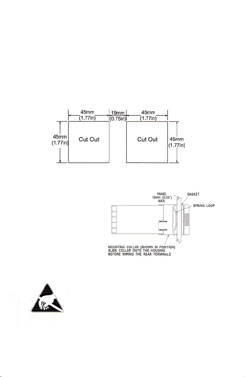
Select the position desired for the instruments on the panel. If more that one
instrument is required, maintain the minimum of spacing requirements as
shown on the drawing below. Closer spacing will structurally weaken the
panel, and invalidate the IP66, UL type 4 rating of the panel.
Prepare the panel by cutting and deburring the required opening.
From the front of the panel, slide the housing through the cut out. The housing
gasket should be against the housing flange before installing.
From the rear of the panel slid the
mounting collar over the housing.
Hold the housing with one hand
and using the other hand, push
the collar evenly against the panel
until the spring loops are slightly
compressed. The ratchets will
hold the mounting collar and
housing in place.
CCaauuttiioonn:: IItt iiss nnoott nneecceessssaarryy ttoo rreemmoovvee tthhee iinnssttrruummeenntt
cchhaassssiiss ffrroomm tthhee hhoouussiinngg ffoorr iinnssttaalll
cchhaassssiiss iiss rreemmoovveedd ffrroomm tthhee hhoouussiinngg,, yyoouu mmuusstt ffoollllooww
iinndduussttrryy ssttaannddaarrdd pprra
aaggaaiinnsstt EElleeccttrroo--SSttaattiicc DDiisscchhaarrggee ((EESSDD)).. FFaaiilluurree ttoo
eexxeerrcciissee ggoooodd E
iinnssttrruummeenntt..
Page 4 of 25
Page 6
WIRING
Do not run thermocouple or other class 2 wiring in the same conduit as power
leads. Use only the type of thermocouple or RTD probe for which the control
has been programmed. Maintain separation between wiring of sensor, auxiliary
in or out, and other wiring. See the “Secure Menu” for input selection.
For thermocouple input always use extension leads of the same type
designated for your thermocouple.
For supply connections use No. 16 AWG or larger wires rated for at least 75°C.
Use copper conductors only. All voltage output circuits must have a common
disconnect and be connected to the same pole of the disconnect.
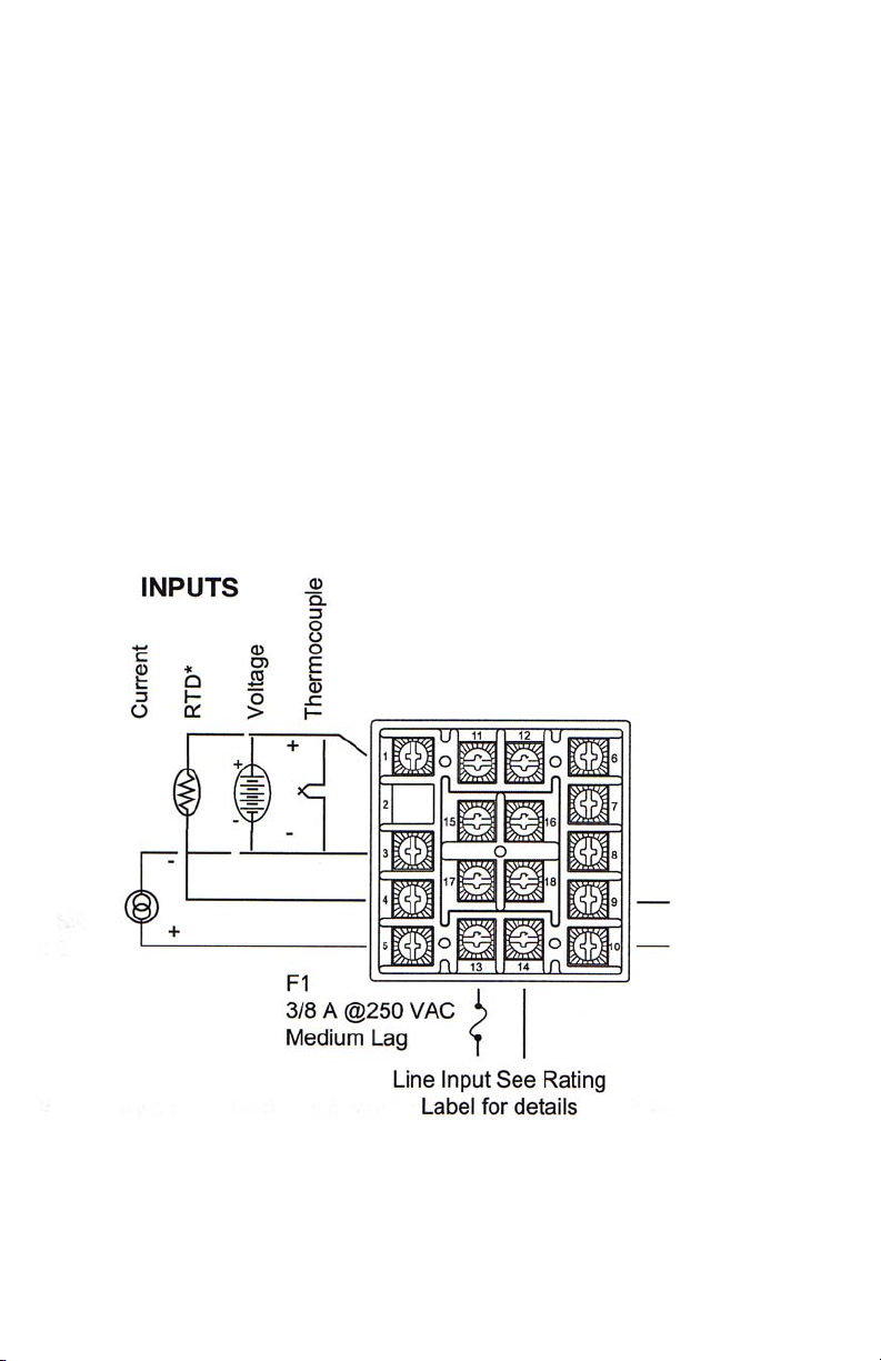
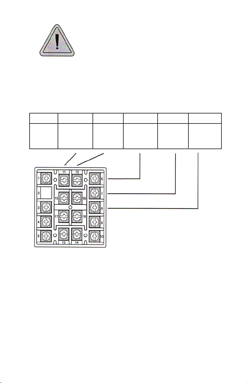
Input wiring for thermocouple, current, and RTD; limit reset function; and output
wiring for the 15VCD is rated CLASS 2.
Control wiring is as shown.
Alarm Reset
An external
normally open
contact may be
wired across
terminals 9 and
10 for remote
reset.
Multiple units
can not share
common
contacts.
Terminals 9 and
10 share a
common
ground with the
input.
• For 2-wire RTD use terminals 1 & 3 and place a jumper wire between
terminal 3 & 4.
Page 5 of 25
Page 7
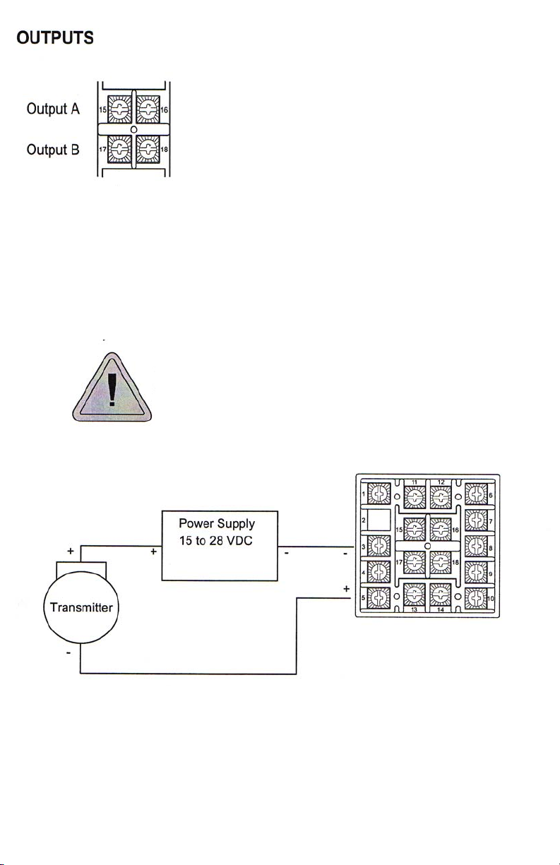
Output A Relay (N.O.) wires to terminals 15 & 16.
Output B Relay (N.C.) wires to terminal 17 & 18.
Wiring for 4 to 20mA Transmitter inputs
Wire power and outputs as shown above. Two-wire transmitters wire as shown
below.
For three of four wire transmitters follow the wiring instructions provided with
your transmitter.
CAUTION: DO NOT WIRE THE 24 VOLT POWER
SUPPLY ACROSS THE INPUT OF THE CONTROL.
DAMAGE TO THE CONTROL INPUT CIRCUITRY WILL
RESULT
Wiring for Optional Inputs and Outputs
Wire power outputs as shown on page 5 and 6. Wiring for options is shown
opposite. All wiring shown below is Class 2.
Page 6 of 25
Page 8
CAUTION: DO NOT RUN SIGNAL WIRING IN THE
SAME CONDUIT OR CHASE AS THE POWER
WIRING. ERRATIC OPERATION OR DAMAGE TO
THE CONTROL CIRCUITRY WILL RESULT.
OPTION
PV1
11
+
12
-
6
NA
7
NA
8
NA
Page 7 of 25
Page 9
FRONT PANEL KEY FUNCTIONS
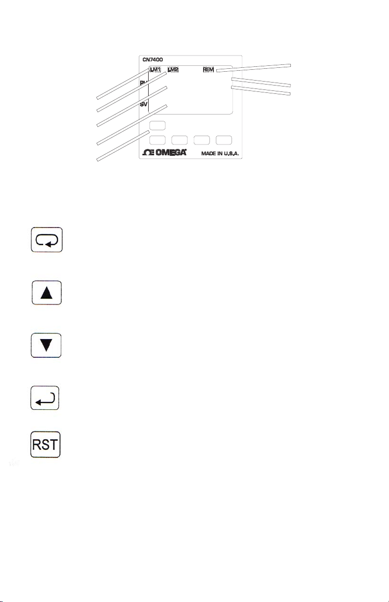
Remote Indicator
°F Indicator
Limit 1 Lamp
Limit 2 Lamp
Process Display
Set Point Display
Limit Reset Key
*Limit Reset key flashes when limit condition is present
Keys are illuminated when pressed. Key functions are as follows.
IINNDDEEXX
: Pressing the INDEX key advances the display to the next
menu item. May also be used in conjunction with other keys as
noted below.
°C Indicator
UUPP AARRRROOWW
: Increments a value, changes a menu item, or selects
the item to ON. The maximum value obtained is 9999 regardless
of decimal point placement.
DDOOWWNN AARRRROOWW
: Decrement a value, changes a menu item, or
selects the item to OFF. The minimum value obtained is -1999
regardless of decimal point placement.
EENNTTEERR
: Pressing ENTER stores the value or the item changed. if
not pressed, the previous stored value or item will be retained. The
display will flash once when ENTER is pressed.
LLIIMMIITT RREESSEETT
: This key resets the limit when the limit condition has
been removed. Press and hold for three seconds to activate.
UUPP AARRRROOWW && EENNTTEERR
sseeccoonndd mmeennuu
starting at the
seconds will bring up the
IINNDDEEXX && DDOOWWNN AARRRROOWW
: Pressing these keys simultaneously brings up the
SSPP11dd
sseeccuurree m
menu item. Pressing these keys for 5
.
: Pressing these keys simultaneously will allow
backing up one menu item, or if at the first menu item they will cause the
display to return to the
pprriimmaarryy mmeennuu
.
Page 8 of 25
Page 10

IINNDDEEXX && EENNTTEERR
seconds allows recovery from the various error messages. The following menu
items will be reset:
: Pressing these keys simultaneously and holding them for 5
SS11iiHH
: Set Point 1 limit inhibit
OOPPEEnn IInnPP
CCoorrrreecctt tthhee pprroobblleemm aassssoocciiaatteedd wwiitthh tthhee aabboovvee ccoonnddiit
rreesseett kkeeyyss
several items are reset at one time.
While in the
seconds, the display will return to HOME position displaying the temperature
value. While in the
seconds, the display will return to the HOME position displaying the
temperature value. Outputs are disabled (turned off) when the
active.
NNOOTTEE
: To move to the
UUPP AARRRROOWW && EENNTTEERR
keys.
: Input error message
. More than one error could be present. Caution is advised since
PPrriimmaarryy ooff SSeeccoonnddaarryy MMeennuu
SSeeccuurree MMeennuu
P
keys followed by pressing the
SS22iiHH
: Set Point 2 limit inhibit
CCHHEECC CCAALL
, if no key is pressed for a period of 30
, if no key is pressed for a period of 60
quickly from any other menu, press the
: Check calibration error
SSeeccuurree MMeennuu
IINNDDEEXX && DDOOWWNN AARRRROOWW
SECURITY LEVEL SELECTION
Four levels of security are provided. The Display shows the current security
level. To change security levels change the password value using the
DDOOWWNN AARRRROOWW
table (following) for the correct value to enter for the security level desired. The
SSEECCrr
regardless of the present security level.
menu item security level may be viewed or changed at any time
keys and pressing the
EENNTTEERR
key. Refer to the password
UUPP &&
is
To set the access level to, for example, 22, at the
AARRRROOWW
EENNTTEERR
upper display.
The password value shown in the table cannot be altered, so retain a copy of
these pages for future reference. This is the only reference made to password
values in this instruction book.
key until the upper display show the password,
key. THe display will blink, and return with the level value, 22, in the
Page 9 of 25
SSEECCrr
menu item press the
11110011
. Press the
UUPP
Page 11

Security Level
Menu Status
PrimaryLocked
Secondary Locked
Secure Locked
PrimaryUnlocked
Secondary Locked
Secure Locked
PrimaryUnlocked
Secondary Unlocked
Secure Locked
Primary Unlocked
Secondary Unlocked
Secure Unlocked
Displayed Value
When Viewed
1
2
3
4
NOTATION CONVENTIONS FOR THE MENUS
Password Value
To Enter
1110
1101
1011
111
Because the number of features available in this control, information is included
that may not apply to your specific control. All usable features are included in
this book, but may not be used in your progress. To increase clarity the
following conventions are used:
1. Certain features, Menu Items, and functions shown in this book may or may
not appear on your control, depending on other Menu item selections. At
various places in the Menus there are notes identifying Menu Items that
“control” or “direct” other menu items. If you are looking for a particular menu
item and can’t find it, check the menu item that is its “control” for proper
setting.
2. The “#” symbol is used in two ways. It is used inside a group of characters
to indicate which set point function (SP1 or SP2) is being affected. It is also
used before a group of characters of a menu item to indicate that there may be
more than one selection or value for that menu.
3. Features that apply only to Options will be printed in Italics.
Page 10 of 25
Page 12

THE HOME DISPLAY
The home display is the normal display while the control is operating. The
HOME display may be programmed to operate in one of three different ways.
This is controlled by the
ddiiSSPP
menu item in the Secure menu.
ddiiSSPP
If
temperature, pressure, flow, RH, etc., that is being measured) on the top
display with the bottom display blank. If
will show only the Set Variable (Set Point 1) on the top display with the bottom
display blank. If
Variable on the top display and the Set Variable on the bottom.
If no errors of functions are active, the HOME display as programmed will be
shown.
is set for
PPrroo
, the home display will show only the Process Variable (the
ddiiSSPP
is set for
ddiiSSPP
is set for
bbootthh
, the HOME display will indicate the Process
SSPPtt
, the home display
OPERATION AND PROGRAMMING OF OPTIONS
Options PV1 isolated Analog Retransmission.
The analog retransmission option allows the Process Variable or the Set
Variable to be sent as an analog signal to an external device. The signal 0 (or
4) to 20 mADC. The output may be changed in the field from one to the other
by the toggle switch located on the top printed circuit board.
Wire the output as shown on page 7.
Set up the analog retransmission, first determine the scale range that the
analog signal will represent. The maximum scale is 9999°F, 5530°C, or 9999
counts. In the Secondary Menu set
represented by the low end of the analog signal (0 Volts or 0 mA). Set
the scale value that will be represented by the high end of the analog signal (10
Volts or 20 mA).
PPOOLL
for the scale value that will be
PPOOHH
for
If you require a suppressed scale or output, you may use the following
equations to determine the proper settings for
KK
= (Highest desired scale reading-Lowest desired scale reading)/
(maximum desired analog signal-Minimum desired analog signal).
PPOOHH
= ((Maximum possible analog output-Maximum desired analog signal) *K)
+ Highest desired analog reading.
Page 11 of 25
PPOOLL
and
PPOOHH
.
Page 13

PPOOLL
= Lowest desired scale reading - ((Minimum desired analog output) *K).
Next select whether you want the retransmission signal to follow the Process
Variable or the Set Variable. Usually the Process Variable is sent to recorders
or other data acquisitions devices. Usually the Set Variable is sent to other
controls to be used as an analog remote set point. If you want the analog
retransmission signal to follow the PV, in the Secondary Menu set
If you want the analog retransmission signal to follow the SV, set
PPOOSSrr
PPOOSSrr
to
to
IInnPP
SSPPtt
Operation is automatic. There are no further programming steps required.
.
.
Page 12 of 25
Page 14
Primary Menu
IINNDDEEXX
Press
DDOOWWNN AARRRROOWW
the value.
SSPP11
to advance to the next menu item. Press
Set Point 1 Adjust, Limit Point 1
Menu Selection
UUPP AARRRROOWW
to change the value in the display. Press
EENNTTEERR
or
to retain
SSPP22
Set Point 2 Adjust (if equipped), Limit Point 2
Secondary Menu
UUPP AARRRROOWW && EENNTTEERR
Hold
UUPP AARRRROOWW
Press
EENNTTEERR
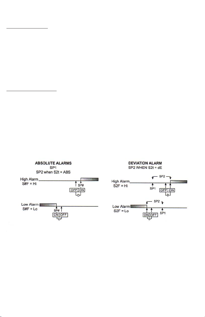
SP1d Set Point On-Off Differential (hysteresis). Select 11to
SS11FF==LLoo
differences between the turn on point (Set Point 1 and the turn off point. See
the following chart.
to retain the value.
) or
--11
to
or
--99999999
. Press
DDOOWWNN AARRRROOWW
(when
IINNDDEEXX
SS11FF==HHii
to advance to the next menu item.
to change the value in the display. Press
99999999
). Set the value for the amount of
(when
TThhee ffoolllloow
ssoott ppooiinnttss ((llaasstt ddiiggiitt ooff mmooddeell
aa sseeccoonndd sseett ppooiinntt,, jjuummpp ttoo tthhee ““SSPP”” mmeennuu iitteemm bbeellooww..
SSPP22dd
Set Point On-Off Differential (hysteresis). Select 11to
SS22FF==LLoo
of difference between the turn on point (Set Point 2) and the turn off
point. See chart above.
) or
--11
to
--99999999
(when
SS22FF==HHii
Page 13 of 25
). Set the value for the amount
99999999
(when
Page 15

PPEEAA
The Peak feature stores the highest input the control has measured
since the last reset or Power On. At Power on
lower display. press the
EENNTTEERR
key to reset.
PPEEAA
must be in the
PPEEAA
will be reset and
display the present input value.
UUAALL
IInnPPCC
FFiiLLTT
PPOOLL
P
The Valley input stores the lowest input the Instrument has measured
since the last reset or Power On. At Power On
present input. To manually reset the value
display. Press the
EEnntteerr
key.
UUAALL
will be reset and display the present
UUAALL
is reset to the
UUAALL
must be in the lowest
input value.
Input correction: Select ±500°F, °C, or counts. This feature allows
the input value to be changed to agree with an external reference or
to compensate for sensor error.
NNoottee
: InPC is reset to zero when the
input type is changed, or when decimal position is changed.
Digital Filter: Select
OOFFFF, 11
9999
to
. In some cases the time constant of
the sensor, or noise could cause the display to jump enough to be
unreadable. A setting of 2 is usually sufficient to provide enough filtering
for most cases, (2 represents approximately a 1 second time constant).
When the 0.1 degree resolution is selected this should be
increased to 4. If this value is set to high, controlability will suffer.
(Option PV1 Analog Retransmission Output) Process Output Low:
Select -450°F, -260°C, or -1999 counts to any value less than
PPOOHH
.
(Option PV1 Analog Retransmission Output) Process Output High:
Select from any value greater then
PPOOLL
to +9999°F, +5530°C, or 9999
counts.
Page 14 of 25
Page 16

SECURE MENU
UUPP AARRRROOWW& EENNTTEERR
Hold
menu item. Press
display. Press
OOUUTTPPUUTTSS AARREE DDIISSAABBLLEEDD ((TTUURRNN OOFFFF)) WWHHIILLEE CCOONNTTRROOLL
MMEENNUU..
SECr Security Code: See the Security Level Selection and the Password
Table
in this manual, in order to enter the correct password.
InP Input Type: Select one of the following. Refer to the input wiring sec
tion for the proper wiring.
OSUP
ZZeerroo
Suppression: Selected
Voltage input types.
OOFFFF
OONN
UUPP AARRRROOWW
EENNTTEERR
JJ--IICC
CCAA
EE--
tt--
LL--
nn--
rr--1133
SS--1100
bb--
CC--
PP339922
nn112200
PP338855
11PP338
CCuurrrr
UUooLLTT
ddiiFFFF
********
THe Input range will start at 0 (zero) Input.
The Input range will start at 4.00 mA or 2.00V.
for 5 seconds. Press
DDOOWWNN AARRRROOWW
or
to retain the value.
Type “J” Thermocouple
Type “K” Thermocouple
Type “E” Thermocouple
Type “T” Thermocouple
Type “L” Thermocouple
Type “N” Thermocouple
Type “R” Thermocouple
Type “S” Thermocouple
Type “B” Thermocouple
Type “C” Thermocouple
100 ohm Platinum (NIST 0.00392 Ω/Ω/°C)
120 ohm Nickel
100 ohm Platinum (DIN 0.00385 Ω/Ω/°C)
1000 ohm Platinum (DIN 0.00385 Ω/Ω/°C)
DC Current Input 0.0 to 20.0 or 4.0 to 20.0 mA
DC Current Input 0.0 to 10.0 or 2.0 to 10.0 mA
DC Voltage Input -10 to +10 mV
Reserved
OOnn
or
IINNDDEEXX
OOFFFF
. Only with Current and
to advance to the next
to change the value in the
Unit
FF, CC
FF
CC
nnoonnEE
NNOONNEE
or
°F descriptor is On and temperature inputs will be displayed in
actual degrees Fahrenheit.
°C descriptor is ON and temperature inputs will be displayed in
actual degrees Celsius.
°F and °C descriptors will be off. This is only available with
current and Voltage Inputs.
Page 15 of 25
Page 17

ddPPTT
Decimal Point Positioning: Select
00,, 00..00,, 00..0000,, 00..000000,, or..00000000
. On
temperature type inputs this will only effect the Process Value, SP1,
SP2, and InPC. For Current and Voltage Inputs all Menu items related
to the input will be affected.
00
No decimal point is selected. This is available for all Input
Types.
00..00
One decimal place is available for Type J, K, E, T, L, RTD’s,
Current and Voltage Inputs.
00..0000
Two decimal places is only available for Current and Voltage
inputs.
00..000000
Three decimal places is only available for Current and Voltage
inputs.
..00000000
Four decimal places is only available for Current and Voltage
inputs.
ddiiSSPP
IInnPPtt
SSEEnnCC
Home Display: Select
PPrroo
The upper display of the upper HOME display shows the cur
PPrroo, SSpptt
, or
bbootthh
.
rent Process Variable. The lower display is blank.
SSPPt
The upper display of the upper HOME display shows the cur
rent Set Variable. The lower display is blank.
bbootthh
The upper display of the upper HOME display shows the cur
rent Process Variable. The lower display shows the current Set
Variable.
Input Fault Timer: Select
OOFFFF, 00..11
to
554400..00
minutes. Whenever an
Input is out of range (UFL or OFL displayed), shorted, or open the
timer will start. When the time has elapsed, the controller outputs will
be forced into their de-energized states. If OFF is Selected, the Input
Fault Timer will not be recognized (time=infinite).
Sensor Rate of Change: Select
OOFFFF, 11
to
44000000
°F, °C, or counts per1
second period. This vault is usually set to be slightly greater than the
fastest process response expected during a 1 second period, but
measured for at least 2 seconds. If the process is faster than this
setting, the SEnC bAd error message will appear. The outputs will then
be turned off. This function can be used to detect a runaway condition,
or speed up detection of an open thermocouple. Use the INDEX and
ENTER keys to reset.
SSCCAALL
Scale Low: Select
between
SSCCAALL
and
110000
SSCCAAHH
to
99999999
counts below
SSCCAAHH
. The total span
must be within 11998 counts. Maximum
setting range is -1999 to +9999 counts. For current and Voltage inputs,
this will set the low range end. Viewable only for Thermocouple and
FTD ranges.
Page 16 of 25
Page 18

SSCCAAHH
Scale High: Select
between
SSCCAALL
and
110000
SSCCAAHH
to
99999999
counts above
SSCCAALL
. The total span
must be within 11998 counts. Maximum
setting range is -1999 to +9999 counts. For Current and Voltage
inputs, this will set the high range end. Viewable only for Thermocouple
and RTD ranges.
SSPPLL
Set point Low: Select from the lowest input range value to
This will set the minimum SP1 or SP2 value that can be entered. The
value for SP1 or SP2 will not stop moving when this value is reached.
SSPPHH
Set point Low: Select from the lowest input range value to
This will set the minimum SP1 or SP2 value that can be entered. The
value for SP1 or SP2 will not stop moving when this value is reached.
SSPP1100
Set Point 1 Output Select: Select AAor
AA
Set Point 1 is routed through Output A, Set Point 2 (if equipped)
is routed through Output B.
AA--bb
Set point 1 is routed through both Output A and Output B. Set
Point 2 menu items are suppressed. This allows for both NO
and NC (Order Code types 3 and 4) outputs to be driven at the
same time.
SS11FF SSeett ppooiinntt 11 FFu
Hi Output is energized above set point.
Lo Output is energized below set point.
SS11rrEE
Set Point 1 Reset. Select
OOnnOOff
Control will automatically reset when process passes back
through
HHooLLdd
manual Reset. Reset (acknowledge) by pressing the
RREESSEETT
OOnnOOff
SSPP11dd
.
key for 3 seconds.
or
HHoolldd
AA--bb
.
SSPPHH
value.
SSPPLL
value.
.
LLIIMMIITT
SS11PPii
SS11iiHH
Set Point 1 Power Interrupt. Select
OOnn
Alarm power Interrupt is
OON
power-up if no alarm condition exists.
OOFFFF
Alarm power Interrupt is
OOFFFF
condition regardless of condition of process.
OOnn
Set Point 1 inhibit: Select
OOnn
Alarm Inhibit is
OOnn
. Alarm action is suspended until the process
or
OOffff
value first enters a non-alarm condition.
OOFFFF
Alarm Inhibit is
OOFFFF
.
Page 17 of 25
OOnn
or
OOFFFF
.
. Control will automatically reset on
. Control will power-up in alarm
.
Page 19

SS11SStt
Set Point 1 State: Select
EEnngg
Output Energized. The output device (per Order Code) will be
energized at set point. (Normally Open contacts will close,
Normally Closed contacts will open.)
ddEEnngg
Output De-energized. The output device (per Order Code) will
be de-energized at set point. (Normally Open contacts will
open, Normally Closed contacts will close.)
EEnngg
or
ddEEnngg
.
SS11LLPP
Set Point Lamp: Select 00on or
OO oonn
OOooFFFF
Lamp ON when Output is On (energized).
Lamp OFF when Output is On (energized).
OOooFFFF
IIff tthhee iinnssttrruummeenntt iiss nnoott eeqquuiippppeedd wwiitthh SSeett P
sseeccttiioonn ((nneexxtt ppaaggee)).. IIff tthhee iinnssttrruummeenntt hhaass nnoo SSeett PPooiinntt 22 aanndd nnoo ooppttiioonnss,, tthheenn
tthhee mmeennuu eennddss..
SS22tt
Set Point 2 type: Select
AAbbSS
Absolute
SSPP22
anywhere between the limits of
ddEE
Deviation
SSPP22
(tracking
SSPP22. SSPP22
to retain is relationship with
SSPP22
)
.
AAbbss
SSPP22
ddEE
or
.
is independent of
SSPPLL
is set as a deviation for
SS
PP11
SSPP11
, and may be set
SSPPHH
and
.
SSPP11
SSPP11
when
, and allows
is changed
SS22FF SSeett PPooiinntt 22 FFuunnccttiioonn:: SSeelleecctt HHii ooff LLoo..
Hi Output is energized above set point.
Lo Output is energized below set point.
SS22rrEE
Set Point 2 Reset. Select
OOnnOOFF
HHooLLdd
Control will automatically reset when process passes back
through
SSPP22dd
Manual. Reset. Reset(acknowledge) by pressing the
RREESSEETT
key for 3 seconds.
OOnnOOFF
or
HHoolldd
.
.
LLIIMMI
SS22PPii
SS22iiHH
Set point 2 power Interrupt.Select
OOnn
Alarm Power Interrupt is
OOnn
Power-up if no alarm condition exists.
OOFFFF
Alarm Power Interrupt is
OOFFFF
condition regardless of condition of process.
Set Point 2 Inhibit: Select
OOnn
Alarm inhibit is
OOnn
or
OOnn
. Alarm action is suspended until the process
value first enters a non-alarm condition.
OOFFFF
Alarm Inhibit is
OOFFFF
Page 18 of 25
OOnn
or
OOFFFF
.
. Control will automatically reset on
. Control will power-up in alarm
OOFFFF
.
Page 20

SS22SStt
Set Point 2 State; Select
EEnngg
Output Energized. The output device (per Order Code) will be
energized at set point. (Normally Open contacts will close,
Normally closed contacts will open.)
ddEEnngg
Output De-energized. The output device (per Order Code) will
be de-energized at set point. (Normally Open contacts will
open, Normally Closed contacts will close.)
EEnngg
or
ddEEnngg
.
SS22LLPP
Set point 2 Lamp: Select
OO oonn
OOooFFFF
Lamp ON when Output is ON (energized).
Lamp OFF when Output is ON (energized).
OO oonn
or
OOooFFFF
.
Page 19 of 25
Page 21

DIAGNOSTIC ERROR MESSAGES
DISPLAY
NNoo
ddiissppllaayy
lliigghhtteedd
FFAAIILL
ttEESStt
CCHHEECC
SSPP11,,
CCHHEECC
SSPP22
CCHHEECC
SSPPLL
oorr
CCHHEECC
SSPPHH
CCHHEECC
LLoorrEE
AArrEEAA
((AAlltteerr--
nnaatteess
wwi
MEANING
Display is blank.
instrument is not getting
power, or the supply
voltage is too low.
Fail test appears upon
power up if the internal
diagnostics detect a fail.
This message may
occur during operation if
failure is detected.
Displays flash.
This message will
appear upon power up
if SP1, SP2, or #SP1 is
set outside of the
SSPPHH
or
values.
This message appears
at power up if SPL or
SPH values are
programmed outside
the input range ends.
This message appears if
the Serial Communications has timed out.
This message appears
when the ambient
temperature of the
control approaches
unacceptable ambiants.
SSPPLL
SP OUTPUTS
Set Point outputs
inactive
Alarm inactive
Set points outputs
inactive
Alarm inactive
Set Point outputs
inactive
Alarm Active
Set points outputs
inactive
Alarm inactive
Set points outputs
inactive
Alarm inactive
Set points outputs
active
Alarm inactive
ACTION REQUIRED
Check that the power supply
is on, or that the external
fuses are good.
The display alternate between
FAIL tESt and one of the
following messages:
FFaaCCttddFFLLtt
corrupted. Press the
key and the
key to start the factory default
presure. Recheck controller
programming. rEt FACt:
Unrecoverable error, return to
factory for service.
Correct the
the
programming new values.
Correct the
values by programming new
values.
Restore the communications
line and switch the LorE to
LOC.
Correct the ambient
temperature conditions.
Ventilate the area of cabinet or
check for clogged filters. If
RJC broken, return to factory
for service.
: Memory may be
DDOOWWNN AARRRROOWW
SSPP11,, eettcc..
SSPPLL
SSPPHH
or
SSPPLL
EENNTTEERR
or adjust
values by
SSPPHH
or
AArrEEAA
This message appears if
the ambient
temperature of the
control is out of range or
RJC sensor is broken.
Set point outputs
active
Alarms active
Page 20 of 25
Correct the ambient
temperature conditions.
Ventilate the area of the
cabinet or check for clogged
filters. If RJC broken, return to
factory for service
Page 22

DIAGNOSTIC ERROR MESSAGES
DISPLAY
UUFFLL
oorr
OOFFLL
bbAAdd
IInnPP
OOPPEEnn
IInnPP
SSEEnnCC
bbAAdd
MEANING
Underflow or Overflow:
Process value has
exceeded input range
ends
UUFFLL
OOFFLL
or
sequence to display on
of these messages if
the InPT is set for a
time value.
For RTD inputs RTD is
open or shorted.
For THERMOCOUPLE
Inputs thermocouple is
open.
Sensor Rate of Change
exceeded the
programmed limits set
for SEnC
will
SP OUTPUTS
Set Point Outputs
active
Alarm active
Set points outputs
inactive
Alarm active
Set Point outputs
inactive
Alarm Active
ACTION REQUIRED
Input signals may normally go
above or below range ends. If
not, check input and correct.
To reset use the
EENNTTEERR
keys. When InPt (input
fault timer) has been set for a
time, the outputs will be turned
off after the set time. Setting
the time to OFF causes the
outputs to remain active,
however
displayed.
Correct or replace sensor. To
reset use the
keys.
Check for the cause of the
error. The value setting may be
to slow for the process, or the
sensor is intermittent. Correct
the problem and press INDEX
and ENTER to reset.
UUFFLL oorr OOFFLL
IINNDDEEXX &&
will still be
IINNDDEEXX && EENNTTEERR
CCHHEECC
CCAALL
Check calibration
appears as the
alternating message if
the instrument
calibration nears
tolerance edges
Check calibration
appears as a flashing
message if the
instrument calibration
exceeds specifications.
Set points outputs
active
Alarm active
Set points outputs
inactive
Alarm active
Page 21 of 25
Remove the instrument for
service and / or recalibration.
To reset use the
EENNTTEERR
keys.
Remove the instrument for
service and / or recalibration.
To reset use the
EENNTTEERR
keys.
IINNDDEEXX &&
IINNDDEEXX &&
Page 23

Specifications
Selectable Inputs: Thermocouple, RTD, DC Voltage, or Current selectable
Input Impedance:
Thermocouple = 3 megohms minimum. RTD current = 200pA
Current = 10 ohms. Voltage = 5000 ohms.
Sensor Break Protection: De-energized output(s) to protect system after
customer set time. (See
Set Point Range: Selectable (See Range Chart Page 26).
Display: Two 4 digit, 7 segment 0.3” high LED’s.
Output Action: Fully programmable to allow output(s) to energize or de-
energize above or below set point(s).
On-Off Differential: Adjustable 1°F, 1°C, 1 count to full scale in 1°F, 1°C, or
1 count steps.
Accuracy: ±0.25% of span, ±1 least significant digit.
Resolution: 1 degree or 0.1 degree, selectable.
Line Voltage Stability: ±0.05% over the supply voltage range.
Temperature Stability: 4µV/°C (2.3 µV/°F) typical, 8 µV/°C (4.5 µV°F)
maximum (100 ppm/°C typical \, 200 ppm/°C maximum).
Common Mode Rejection: 140 db Minimum at 60 Hz
Normal Mode Rejection: 65 db typical, 60 db at 60 Hz
Isolation:
Relay outputs: 1500 Vac to all other inputs and outputs.
Process output PV1: 500 VAC to all other inputs and outputs.
Supply Voltage: 100 to 240 Vac, nominal., +10-15%, 50to 400 Hz. single
phase; 132 to 240 VDC, nominal., +10-20%
Option-LV: 12 to 24 VDC/VAC, 50 to 400 Hz ±20%.
Power Consumption: 5VA maximum.
Operating temperature: -10 to +55°C (+14 to 131°F).
Storage Temperature: -40 to +80°C (-40 to 176°F).
Humidity Conditions: 0 to 90% up to 40°C non condensing 10 to 50% at
55°C non-condensing.
Memory backup: Nonvolatile memory. No batteries required.
Output Ratings:
Relay: SPST, 3 A@ 240 Vac resistive; 1.5A @240 Vac inductive;
Pilot duty rating 240 VA, 2 A @120 Vac or 1 A 240 Vac.
IInnPPtt
in Secondary Menu.)
Page 22 of 25
Page 24
P
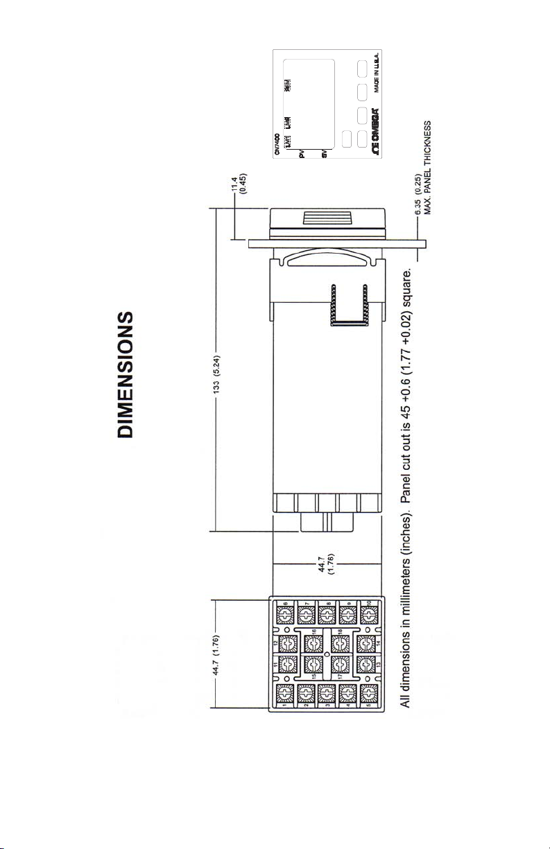
anel Cutout: 45 mm X 45mm (1.775”X1.775”).
Depth Behind mounting Surfaces: 121.6 mm (4.79”), maximum
Weight: 220 g (8 oz.)
Agency Approvals: FM
Front Panel Rating: IP66, (NEMA4X)
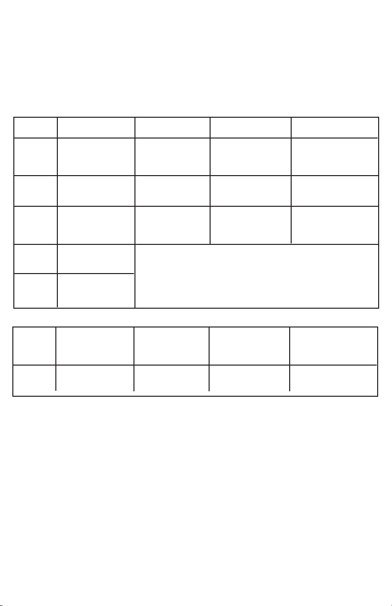
Input Ranges (Field Selected)
Thermocouple Types
Input
Type
Range
1°F
1°C
Type J or L
100 to +1600
-73 to +871
Type K*
-200 to +2500
-129 to +1371
Type T*
-350 to +750
-212 to +398
Type E*
-100 to +1800
-73 to +982
Input
Type
Range
1°F
1°C
Input
Type
Range
1°F
1°C
Type R
0 to 3200
-17 to +1760
Type N*
-100 to +2372
-73 to +1300
Type S
0 to 3200
-17 to +1760
Type B
+75 to 3308
-24 to +1820
*These Input Types can be set for 0.1” display.
If temperature goes above 999.9° or less than
-199.9° the display will return to whole degree
resolution.
Type C
0 to 4208
-17 to +2320
RTD Types
Input
Type
Range
1°F
1°C
100 Ohm
Platinum
0.00385 DIN
Curve*
-328 to +1607
-200 to +875
100 Ohm
Platinum
0.00392 Nist
Curve*
-328 to +1607
-200 to +875
100 Ohm
Platinum
0.00628 US
Curve*
-112 to +608
-80 to +320
100 Ohm
Platinum
0.00385 Nist
Curve*
-328 to +1607
-200 to +875
Process Input Types
The 0 to 20 mAdc, 4 to 20 mAdc, 0 to Vdc, 2 to 10 Vcd, and -10 to
+10 mVdc inputs are fully scalable from a Minimum of 100 counts
span placed anywhere within the range of -1999 to +9999. Decimal
point position is adjustable from the zero place (9999), tenths (999.9),
hundreths (99.99), thousandths (9.999), or ten thousandths (.9999).
Page 23 of 25
Page 25
Page 24 of 25
Page 26

WARRANTY/DISCLAIMER
OMEGA ENGINEERING, INC. warrants this unit to be free of defects in materials and workmanship for a
period of 13 months from date of purchase. OMEGA’s WARRANTY adds an additional one (1) month grace
period to the normal one (1) year product warranty to cover handling and shipping time. This ensures
that OMEGA’s customers receive maximum coverage on each product.
If the unit malfunctions, it must be returned to the factory for evaluation. OMEGA’s Customer Service
Department will issue an Authorized Return (AR) number immediately upon phone or written request.
Upon examination by OMEGA, if the unit is found to be defective, it will be repaired or replaced at no
charge. OMEGA’s WARRANTY does not apply to defects resulting from any action of the purchaser,
including but not limited to mishandling, improper interfacing, operation outside of design limits,
improper repair, or unauthorized modification. This WARRANTY is VOID if the unit shows evidence of
having been tampered with or shows evidence of having been damaged as a result of excessive corrosion;
or current, heat, moisture or vibration; improper specification; misapplication; misuse or other operating
conditions outside of OMEGA’s control. Components in which wear is not warranted, include but are not
limited to contact points, fuses, and triacs.
OMEGA is pleased to offer suggestions on the use of its various products. However,
OMEGA neither assumes responsibility for any omissions or errors nor assumes liability for
any damages that result from the use of its products in accordance with information provided
by OMEGA, either verbal or written. OMEGA warrants only that the parts manufactured by the
company will be as specified and free of defects. OMEGA MAKES NO OTHER WARRANTIES OR
REPRESENTATIONS OF ANY KIND WHATSOEVER, EXPRESSED OR IMPLIED, EXCEPT THAT OF
TITLE, AND ALL IMPLIED WARRANTIES INCLUDING ANY WARRANTY OF MERCHANTABILITY
AND FITNESS FOR A PARTICULAR PURPOSE ARE HEREBY DISCLAIMED. LIMITATION OF
LIABILITY: The remedies of purchaser set forth herein are exclusive, and the total liability of
OMEGA with respect to this order, whether based on contract, warranty, negligence,
indemnification, strict liability or otherwise, shall not exceed the purchase price of the
component upon which liability is based. In no event shall OMEGA be liable for
consequential, incidental or special damages.
CONDITIONS: Equipment sold by OMEGA is not intended to be used, nor shall it be used: (1) as a “Basic
Component” under 10 CFR 21 (NRC), used in or with any nuclear installation or activity; or (2) in medical
applications or used on humans. Should any Product(s) be used in or with any nuclear installation or
activity, medical application, used on humans, or misused in any way, OMEGA assumes no responsibility
as set forth in our basic WARRANTY/DISCLAIMER language, and, additionally, purchaser will indemnify
OMEGA and hold OMEGA harmless from any liability or damage whatsoever arising out of the use of the
Product(s) in such a manner.
RETURN REQUESTS/INQUIRIES
Direct all warranty and repair requests/inquiries to the OMEGA Customer Service Department. BEFORE
RETURNING ANY PRODUCT(S) TO OMEGA, PURCHASER MUST OBTAIN AN AUTHORIZED RETURN (AR)
NUMBER FROM OMEGA’S CUSTOMER SERVICE DEPARTMENT (IN ORDER TO AVOID PROCESSING
DELAYS). The assigned AR number should then be marked on the outside of the return package and on any
correspondence.
The purchaser is responsible for shipping charges, freight, insurance and proper packaging to prevent
breakage in transit.
FOR WARRANTY RETURNS, please have the
following information available BEFORE contacting
OMEGA:
1. Purchase Order number under which the product
was PURCHASED,
2. Model and serial number of the product under
warranty, and
3. Repair instructions and/or specific problems
relative to the product.
OMEGA’s policy is to make running changes, not model changes, whenever an improvement is possible. This affords our
customers the latest in technology and engineering.
OMEGA is a registered trademark of OMEGA ENGINEERING, INC.
© Copyright 2017 OMEGA ENGINEERING, INC. All rights reserved. This document may not be copied, photocopied,
reproduced, translated, or reduced to any electronic medium or machine-readable form, in whole or in part, without the prior
written consent of OMEGA ENGINEERING, INC.
FOR NON-WARRANTY REPAIRS, consult
OMEGA for current repair charges. Have
the following information available BEFORE
contacting OMEGA:
1. Purchase Order number to cover the COST
of the repair,
2. Model and serial number of the product, and
3. Repair instructions and/or specific problems
relative to the product.
Page 27

Where Do I Find Everything I Need for
Process Measurement and Control?
OMEGA…Of Course!
Shop online at omega.com
TEMPERATURE
MU
Thermocouple, RTD & Thermistor Probes, Connectors,
Panels & Assemblies
MU
Wire: Thermocouple, RTD & Thermistor
MU
Calibrators & Ice Point References
MU
Recorders, Controllers & Process Monitors
MU
Infrared Pyrometers
PRESSURE, STRAIN AND FORCE
MU
Transducers & Strain Gages
MU
Load Cells & Pressure Gages
MU
Displacement Transducers
MU
Instrumentation & Accessories
FLOW/LEVEL
MU
Rotameters, Gas Mass Flowmeters & Flow Computers
MU
Air Velocity Indicators
MU
Turbine/Paddlewheel Systems
MU
Totalizers & Batch Controllers
pH/CONDUCTIVITY
MU
pH Electrodes, Testers & Accessories
MU
Benchtop/Laboratory Meters
MU
Controllers, Calibrators, Simulators & Pumps
MU
Industrial pH & Conductivity Equipment
DATA ACQUISITION
MU
Communications-Based Acquisition Systems
MU
Data Logging Systems
MU
Wireless Sensors, Transmitters, & Receivers
MU
Signal Conditioners
MU
Data Acquisition Software
HEATERS
MU
Heating Cable
MU
Cartridge & Strip Heaters
MU
Immersion & Band Heaters
MU
Flexible Heaters
MU
Laboratory Heaters
ENVIRONMENTAL
MONITORING AND CONTROL
MU
Metering & Control Instrumentation
MU
Refractometers
MU
Pumps & Tubing
MU
Air, Soil & Water Monitors
MU
Industrial Water & Wastewater Treatment
MU
pH, Conductivity & Dissolved Oxygen Instruments
M4442/1017
 Loading...