

Page 1
CN63500
Temperature Limit Alarm
INSTRUCTION
SHEET
M4497-0513
Shop online at: omega.com e-mail: [email protected]
For latest product manuals: omegamanual.info
FM
APPROVED
PROCESS CONTROL EQUIPMENT
UL Recognized Component,
File # E123489
GENERAL DESCRIPTION
The CN63500 is a Factory Mutual approved temperature limit alarm,
intended to provide an independent shutdown for thermal processes. The
CN63500 accepts signals from a variety of temperature sensors (thermocouple
or RTD elements), and its comprehensive programming allows it to meet a wide
variety of application requirements.
Dual 4-digit displays allow viewing of the process temperature and limit
setpoint simultaneously. Front panel indicators inform the operator of the
process and output status. The main limit output and alarm outputs are field
replaceable.
The limit output is selectable for high or low trip activation. If the process
temperature goes above the limit setpoint for a high trip, or below the limit
setpoint for a low trip, the limit relay will de-energize to initiate a process
shutdown. The limit output cannot be reset until the process temperature returns
to the proper operating range; manual reset is required (local or remote). Sensor
failure will initiate a process shutdown.
Relay alarm(s) can be configured to activate according to a variety of actions
(Absolute HI or LO, Deviation HI or LO, and Band IN or OUT) with adjustable
hysteresis. A standby feature suppresses the alarm during power-up until the
process stabilizes outside the alarm region.
The unit is constructed of a lightweight, high impact plastic case with a tinted
front panel. The front panel meets NEMA 4X/IP65 specifications when properly
FM APPROVED, UL RECOGNIZED
2-LINE BY 4-DIGIT DISPLAY
EXCEED, OUTPUT, AND ALARM ANNUNCIATORS
FOUR BUTTON SILICONE RUBBER KEYPAD
THERMOCOUPLE OR RTD SENSOR INPUT
REMOTE RESET INPUT
MAIN LIMIT OUTPUT: 5A RELAY. SELECTABLE FOR HIGH OR
LOW TRIP ACTIVATION
OPTIONAL ALARMS: 5A RELAY(S)
OPTIONAL NEMA 4X/IP65 SEALED FRONT BEZEL
PARAMETER SECURITY VIA PROGRAMMABLE LOCKOUTS
installed. Multiple units can be stacked horizontally or vertically. Modern
surface-mount technology, extensive testing, plus high immunity to noise
interference makes the CN63500 extremely reliable in industrial environments.
SAFETY SUMMARY
All safety related regulations, local codes and instructions that appear in the
manual or on equipment must be observed to ensure personal safety and to
prevent damage to either the instrument or equipment connected to it. If
equipment is used in a manner not specified by the manufacturer, the protection
provided by the equipment may be impaired.
Do not use the CN63500 to directly command motors, valves, or other
actuators not equipped with safeguards. To do so can be potentially harmful to
persons or equipment in the event of a fault to the unit.
CAUTION: Risk of Danger.
Read complete instructions prior to
installation and operation of the unit.
CAUTION: Risk of electric shock.
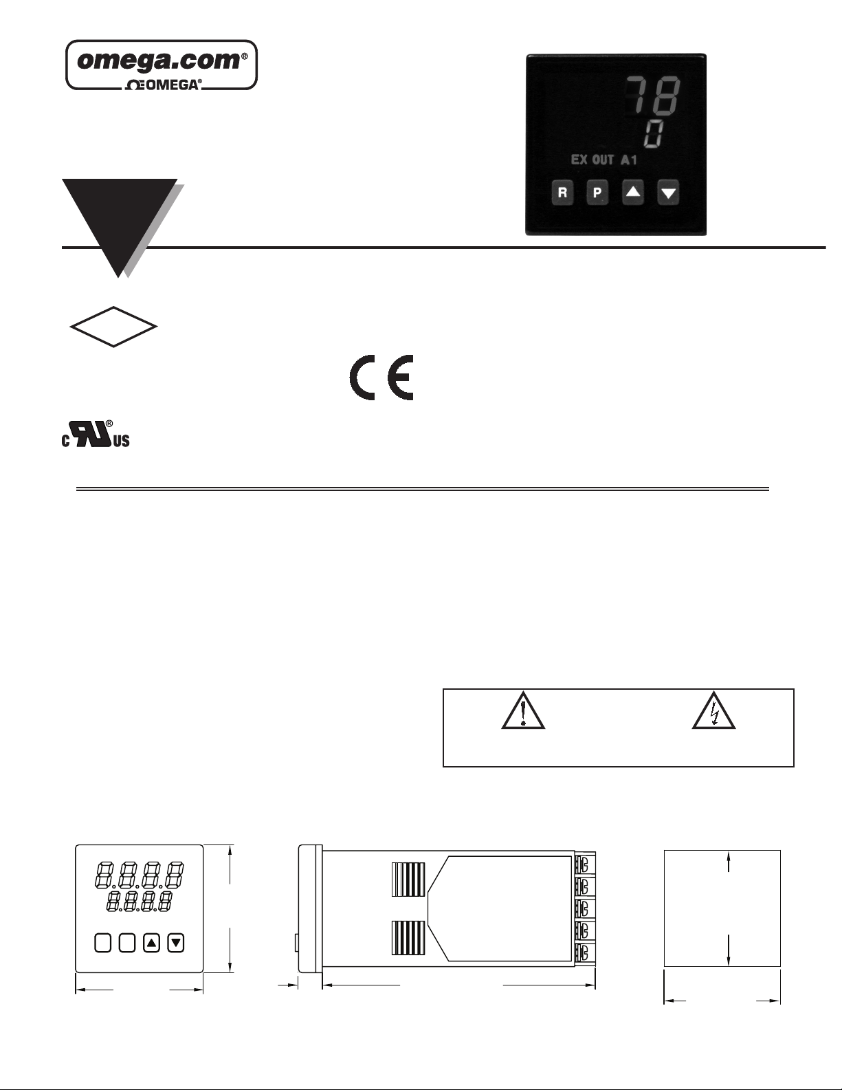
DIMENSIONS In inches (mm)
1.95
EX OUT A1 A2
PR
1.95
(49.5)
(49.5)
0.37
(9.4)
4.17 (105.9)
PANEL CUT-OUT
+0.024
1.772
-0.000
+0.6
(45 )
-0.0
+0.024
1.772
-0.000
+0.6
(45 )
-0.0
LP0682A
Page 2

GENERAL SPECIFICATIONS
1. DISPLAY: 2 line by 4-digit LED
Upper (Main) Display: 0.4" (10.2 mm) high red LED
Lower (Secondary) Display: 0.3" (7.6 mm) high green LED
Display Messages:
“OLOL” - Appears when measurement exceeds + sensor range.
“ULUL” - Appears when measurement exceeds - sensor range.
“OPEN” - Appears when open sensor is detected.
“SHrt” - Appears when shorted sensor is detected (RTD only)
“...” - Appears when display values exceed + display range.
“-..” - Appears when display values exceed - display range.
LED Status Annunciators:
EX - Temperature exceeds limit setpoint
OUT - Limit output is de-energized
A1 - Alarm #1 is active
A2 - Alarm #2 is active
2. POWER:
Line Voltage Models: 85 to 250 VAC, 50/60 Hz, 8 VA.
Low Voltage Models:
DC Power: 18 to 36 VDC, 7 W.
AC Power: 24 VAC +/-10%, 50/60 Hz, 9 VA
3. CONTROLS: Four rubber push buttons: R, P, Up, Down
4. MEMORY: Nonvolatile E2PROM retains all programmable parameters and
values.
5. ENVIRONMENTAL CONDITIONS:
Operating Range: FM rated @ 0 to 65°C, UL rated @ 0 to 55°C
Storage Range: -40 to 80°C
Operating and Storage Humidity: 85% max. relative humidity (non-
condensing) from 0°C to 65°C.
Vibration to IEC 68-2-6: Operational 5 to 150 Hz, 2g.
Shock to IEC 68-2-27: Operational 20 g (10g relay)
Altitude: Up to 2000 meters
6. ISOLATION BREAKDOWN RATINGS:
AC line with respect to all inputs and outputs: 2300 V for 1 minute (250
V working)
Relay contacts to all other inputs and outputs: 2300 VAC
DC Power with respect to sensor input: 50 V working (500 V for 1 minute)
7. CERTIFICATIONS AND COMPLIANCES:
CE Approved
EN 61326-1 Immunity to Industrial Locations
Emission CISPR 11 Class A
IEC/EN 61010-1
RoHS Compliant
Factory Mutual (FM) Listed: File #3030454
UL Recognized Component, File #E123489
Type 4X Enclosure rating (Face only)
IP65 Enclosure rating (Face only)
IP20 Enclosure rating (Rear of unit)
Refer to EMC Installation Guidelines section of the bulletin for additional
information.
8. CONNECTION: Wire clamping screw terminals
Wire Gage Capacity: Two 14 AWG (2.55 mm), four 18 AWG (1.02 mm), or
four 20 AWG (0.61 mm).
Terminal Torque: 1.0Nm (8.9 in-lbs.).
1.4Nm (12.4 in-lbs.) max.
9. CONSTRUCTION: Black plastic alloy case and collar style panel latch.
Panel latch can be installed for vertical or horizontal instrument stacking.
One piece tinted plastic bezel. Bezel assembly with circuit boards can be
removed from the case to change the output board without removing the case
from the panel or disconnecting wiring. Unit meets NEMA 4X/IP65
requirements for indoor use, when properly installed. Flame resistant.
Installation Category II, Pollution Degree 2.
10. WEIGHT: 0.38 lbs (0.17 kgs)
INPUT SPECIFICATIONS
1. SENSOR INPUT:
Sample Period: 100 msec
Step Response Time: Less than 300 msec typ., 400 msec max. (to within
99% of final value)
Normal Mode Rejection: Greater than 40 dB @ 50/60 Hz
Common Mode Rejection: Greater than 120 dB, DC to 60 Hz
Overvoltage Protection: Input overload 120 VAC for 15 seconds max.
2. Failed Sensor Response:
Main Output: Sensor failure will initiate a process shutdown
Display: “OPEN”
Alarms: Upscale
3. INDICATION ACCURACY: ±(0.3% of Span +1°C) at 23°C ambient after
20 minute warm-up. (Includes NIST conformity, cold junction effect, A/D
conversion errors and linearization conformity.
Span Drift (maximum): 130 PPM/°C
4. RTD INPUT: 2 or 3 wire, 100 Ω platinum, alpha = 0.00385 (DIN 43760),
alpha = 0.0039162
Excitation: 150 µA typical
Resolution: 1 or 0.1 degree
Lead Resistance: 15 Ω max. per input lead
RTD TYPE RANGE
385
392
OHMS 2.0 to 320.0
-200 to +600°C
-328 to +1100°F
-200 to +600°C
-328 to +1100°F
5. THERMOCOUPLE INPUT:
Types: T, E, J, K, R, S, B, N, Linear mV, software selectable
Input Impedance: 20 MΩ all types
Lead resistance effect: 0.25 µV/Ω
Cold junction compensation: Less than ±1°C typ., (±1.5°C max), error over
0 to 65°C max. ambient temperature range. Defeated for Linear mV
indication mode.
Resolution: 1° for all types, or 0.1° for T, E, J, K, and N only.
WIRE COLOR
blue (+)
red (-)
violet (+)
red (-)
white (+)
red (-)
yellow (+)
red (-)
black (+)
red (-)
black (+)
red (-)
grey (+)
red (-)
orange (+)
red (-)
BS 1843ANSI
white (+)
blue (-)
brown (+)
blue (-)
yellow (+)
blue (-)
brown (+)
blue (-)
white (+)
blue (-)
white (+)
blue (-)
no standard
orange (+)
blue (-)
no standardno standard-5.00 to +56.00
T
E
J
K
R
S
B
N
mV
RANGETC TYPE
-200 to +400°C
-328 to +752°F
-200 to +750°C
-328 to +1382°F
-200 to +760°C
-328 to 1400°F
-200 to +1250°C
-328 to +2282°F
0 to 1768°C
+32 to +3214°F
0 to 1768°C
+32 to 3214°F
+149 to +1820°C
+300 to +3308°F
-200 to +1300°C
-328 to +2372°F
6. REMOTE RESET INPUT: Internally pulled up to +5 VDC (1MΩ).
VIL: 0.85 V max., VIH: 3.65 V min., VIN MAX: 5.25 VDC, I
2
: 1µA max.
OFF
Page 3
OUTPUT SPECIFICATIONS
1. LIMIT AND ALARM OUTPUT RELAYS:
Contact Rating: 5 A @ 250 VAC or 30 VDC (resistive load).
Life Expectancy: 100,000 cycles at max. load rating. (Decreasing load
increases life expectancy.)
2. LIMIT OUTPUT: CN63500-R1-AL1: Form-C relay; CN63500R1-AL2:
Form-A relay. Selectable for high or low trip activation. If the process
temperature goes above the limit setpoint for a high trip, or below the limit
setpoint for a low trip, the limit relay will de-energize to initiate a process
shutdown. The limit output cannot be reset until the process temperature
returns to the proper operating range; manual reset is required (local or
remote).
Annunciators:
“EX” - Lit when the process temperature exceeds the limit setpoint.
“OUT” - Lit when the limit output is de-energized.
3. ALARM OUTPUTS (Optional): One or two Form-A relays.
Modes:
Absolute High Acting Absolute Low Acting
Deviation High Acting Deviation Low Acting
Inside Band Acting Outside Band Acting
Reset Action: Programmable; automatic or latched. Latched alarms can be
reset regardless of limit exceed condition.
Standby Mode: Programmable; enable or disable.
Hysteresis: Programmable.
Annunciator: “A1” and “A2” programmable for normal or reverse acting.
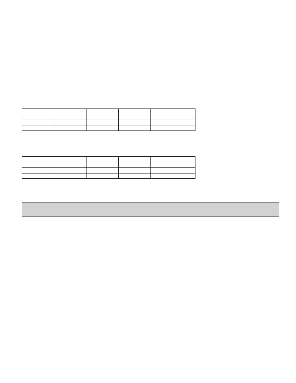
PART NUMBERS
85 to 250 VAC
REPLACEMENT
OUTPUT BOARD
CN6-RBDLA210
CN6-RBD48111
18 to 36 VDC / 24 VAC
LIMIT OUTPUT ALARM 1 OUTPUT ALARM 2 OUTPUT PART NUMBERS
Form-C Relay Form-A Relay CN63500-R1-AL1-LV
Form-A Relay Form-A Relay Form-A Relay CN63500-R1-AL2-LV
REPLACEMENT
OUTPUT BOARD
CN6-RBDLA210
CN6-RBD48111
PART NUMBERSALARM 2 OUTPUTALARM 1 OUTPUTLIMIT OUTPUT
CN63500-R1-AL1Form-A RelayForm-C Relay
CN63500-R1-AL2Form-A RelayForm-A RelayForm-A Relay
EMC INSTALLATION GUIDELINES
Although this unit is designed with a high degree of immunity to Electromagnetic
Interference (EMI), proper installation and wiring methods must be followed to
ensure compatibility in each application. The type of the electrical noise, source
or coupling method into a unit may be different for various installations. Cable
length, routing, and shield termination are very important and can mean the
difference between a successful or troublesome installation. Listed are some
EMI guidelines for a successful installation in an industrial environment.
1. A unit should be mounted in a metal enclosure, which is properly connected
to protective earth.
2. Use shielded cables for all Signal and Control inputs. The shield connection
should be made as short as possible. The connection point for the shield
depends somewhat upon the application. Listed below are the recommended
methods of connecting the shield, in order of their effectiveness.
a. Connect the shield to earth ground (protective earth) at one end where the
unit is mounted.
b. Connect the shield to earth ground at both ends of the cable, usually when
the noise source frequency is over 1 MHz.
3. Never run Signal or Control cables in the same conduit or raceway with AC
power lines, conductors, feeding motors, solenoids, SCR controls, and
heaters, etc. The cables should be run through metal conduit that is properly
grounded. This is especially useful in applications where cable runs are long
and portable two-way radios are used in close proximity or if the installation
is near a commercial radio transmitter. Also, Signal or Control cables within
an enclosure should be routed as far away as possible from contactors,
control relays, transformers, and other noisy components.
4. Long cable runs are more susceptible to EMI pickup than short cable runs.
5. In extremely high EMI environments, the use of external EMI suppression
devices such as Ferrite Suppression Cores for signal and control cables is
effective.6. To protect relay contacts that control inductive loads and to
minimize radiated and conducted noise (EMI), some type of contact
protection network is normally installed across the load, the contacts or both.
The most effective location is across the load.
a. Using a snubber, which is a resistor-capacitor (RC) network or metal oxide
b. If a DC inductive load (such as a DC relay coil) is controlled by a transistor
7. Care should be taken when connecting input and output devices to the
instrument. When a separate input and output common is provided, they
should not be mixed. Therefore a sensor common should NOT be connected
to an output common. This would cause EMI on the sensitive input common,
which could affect the instrument’s operation.
varistor (MOV) across an AC inductive load is very effective at reducing
EMI and increasing relay contact life.
switch, care must be taken not to exceed the breakdown voltage of the
transistor when the load is switched. One of the most effective ways is to
place a diode across the inductive load. External diode protection at the
load is always a good design practice to limit EMI. Although the use of a
snubber or varistor could be used.
3
Page 4
1.96 (49.8)
2.39 (60.7)
1.96 (49.8)
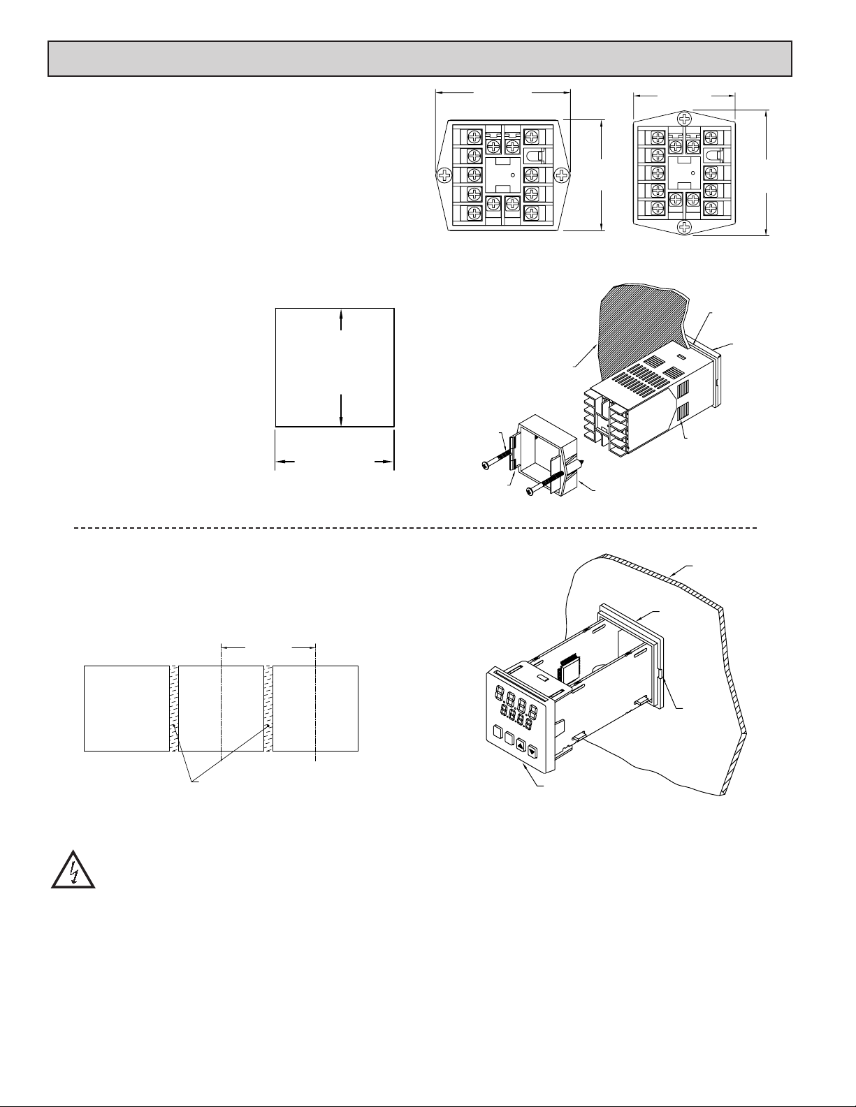
1.0 INSTALLING THE CN63500
The CN63500 meets NEMA 4X/IP65 requirements for indoor use to provide
a watertight seal in steel panels with a minimum thickness of 0.09 inch, or
aluminum panels with a minimum thickness of 0.12 inch. The units are intended
to be mounted into an enclosed panel. It is designed so that the units can be
stacked horizontally or vertically. The bezel assembly MUST be in place during
installation of the unit.
Instructions:
1. Prepare the panel cutout to the dimensions.
2. Remove the panel latch from the unit. Discard the cardboard sleeve.
3. Carefully remove the center section of the panel gasket and discard. Slide
the panel gasket over the unit from the rear, seating it against the lip at the
front of the case.
4. Insert the unit into the panel cutout. While holding the unit in place, push the
panel latch over the rear of the unit, engaging the tabs of the panel latch in
the farthest forward slot possible.
5. To achieve a proper seal, tighten the
panel latch screws evenly until the unit
is snug in the panel, torquing the screws
to approximately 7 in-lbs (79 N-cm).
Over tightening can result in distortion
of the panel, and reduce the effectiveness
of the seal.
Note: The installation location of the
CN63500 is important. Be sure to keep it
away from heat sources (ovens, furnaces,
etc.), and away from direct contact with
caustic vapors, oils, steam, or any other
process byproducts in which exposure
may affect proper operation.
1.772
1.772
(45 )
(45 )
+0.6
-0.0
+0.024
-0.000
+0.6
-0.0
+0.024
-0.000
MAX.
13 14
1
2
3
4
5
PANEL LATCH INSTALLED FOR
VERTICAL UNIT STACKING
PANEL
MOUNTING
SCREW
LATCHING
TABS
6
7
8
9
10
1211
PANEL
1.96 (49.8)
MAX.
PANEL LATCH
MAX.
13 14
1
2
3
4
5
PANEL LATCH INSTALLED FOR
HORIZONTAL UNIT STACKING
6
7
8
10
1211
PANEL GASKET
LATCHING
SLOTS
2.39 (60.7)
9
BEZEL
MAX.
Multiple Unit Stacking
The CN63500 is designed for close spacing of multiple units. Units can be
stacked either horizontally or vertically. For vertical stacking, install the panel
latch with the screws to the sides of the unit. For horizontal stacking, the panel
latch screws should be at the top and bottom of the unit. The minimum spacing
from center line to center line of units is 1.96" (49.8 mm). This spacing is the
same for vertical or horizontal stacking.
MIN.
STANDARD
PANEL
CUT-OUT
IF NEMA 4 IS NOT REQUIRED,
THIS PANEL MATERIAL MAY BE REMOVED.
Note: When stacking units, provide adequate panel ventilation to ensure that
the maximum operating temperature range is not exceeded.
Caution: Disconnect power to the unit and to the output control circuits
to eliminate the potential shock hazard when removing the bezel
assembly.
Unit Removal Procedure
To remove a unit from the panel, first loosen the panel latch screws. Insert
flat blade screwdrivers between the latch and the case on either side of the unit,
so that the latches disengage from the grooves in the case. Push the unit through
the panel from the rear.
Removing Bezel Assembly
The bezel assembly must be removed from the case to replace the output
board. To remove the bezel assembly, insert a flat blade screwdriver into the pry
slot on either side of the unit. Twist the screwdriver handle until the unit is
ejected enough to allow removal.
PANEL
CASE
LIP
EB0783
PRY
SLOT
R P
BEZEL
Caution: The bezel assembly contains electronic circuits that can be damaged
by static electricity. Before removing the assembly, discharge static charge on
your body by touching an earth ground point. It is also important that the
bezel assembly be handled only by the bezel itself. Additionally, if it is
necessary to handle a circuit board, be certain that hands are free from dirt,
oil, etc., to avoid circuit contamination that may lead to malfunction. If it
becomes necessary to ship the unit for repairs, place the unit in its case
before shipping.
Installing Bezel Assembly
To install the bezel assembly, insert the assembly into the case until the bezel
is fully seated against the lip of the case. Properly installing the bezel assembly
is necessary for watertight sealing.
4
Page 5
2.0 WIRING THE CN63500
After the unit has been mechanically mounted, it is ready to be wired. All
wiring connections are made to the rear screw terminals. When wiring the unit,
use the numbers on the label and those embossed on the back of the case, to
identify the position number with the proper function.
All conductors should meet voltage and current ratings for each terminal.
Also cabling should conform to appropriate standards of good installation, local
codes and regulations. It is recommended that power supplied to the unit (AC
or DC) be protected by a fuse or circuit breaker. Strip the wire, leaving
approximately 1/4" (6 mm) bare wire exposed (stranded wires should be tinned
with solder). Insert the wire under the clamping washer and tighten the screw
until the wire is clamped tightly.
Caution: Unused terminals are NOT to be used as tie points. Damage to the
CN63500 may result if these terminals are used.
POWER WIRING
AC Power
Primary AC power is connected to terminals #11 and #12, labeled AC. To
reduce the chance of noise spikes entering the AC line and affecting the
CN63500, an AC feed separate from that of the load should be used to power
the CN63500. Be certain that the AC power to the CN63500 is relatively
“clean” and within the variation limit. Connecting power from heavily loaded
circuits or circuits that also power loads that cycle on and off (contacts, relays,
motors, etc.), should be avoided.
DC Power
DC Power (18 to 36 VDC) is connected to terminals #11 and #12 labeled
DC+ and DC- respectively.
CAUTION: Observe proper polarity when connecting DC voltages.
Damage to the unit may occur if polarity is reversed.
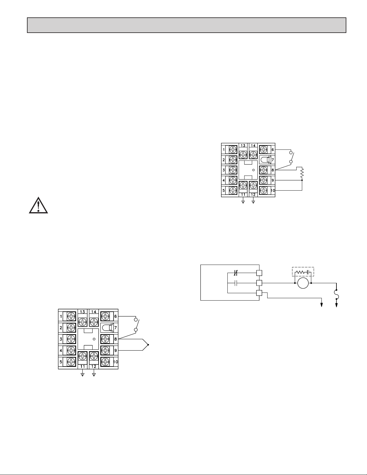
RTD
When connecting the RTD, be certain that the connections are clean and
tight. RTD sensors have a higher degree of accuracy and stability than
thermocouple sensors. Most RTD sensors available are the three wire type. The
third wire is a sense lead for canceling the effects of lead resistance of the probe.
Four wire RTD elements may be used by leaving one of the sense leads
disconnected. Two wire RTD sensors may be used in either of two ways:
A) Attach the RTD to terminals #8 and #10. Install a copper sense wire of the
same wire gauge as the RTD leads. Attach one end of the wire at the probe
and the other end to terminal #9. Complete lead wire compensation is
obtained. This is the preferred method.
B) Attach the RTD to terminals #8 and #10. Install a shorting wire between
terminals #9 and #10. A temperature offset error of 2.5°C/ohm of lead
resistance exists. The error may be compensated by programming a
temperature offset.
Note: With extended cable runs, be sure the lead resistance is less than 15 ohms/
lead.
USER INPUT
COMM.
RTD
POWER
RTD Connection
RTD
PROBE
SIGNAL WIRING
Thermocouple
When connecting the thermocouple, be certain that the connections are clean
and tight. If the thermocouple probe cannot be connected directly to the
CN63500, thermocouple wire or thermocouple extension-grade wire must be
used to extend the connection points (copper wire does not work). Always refer
to the thermocouple manufacturer’s recommendations for mounting, temperature
range, shielding, etc. For multi-probe temperature averaging applications, two
or more thermocouple probes may be connected to the CN63500 (always use
the same type). Paralleling a single thermocouple to more than one CN63500 is
not recommended. Generally, the red wire from the thermocouple is negative
and connected to the CN63500’s common.
USER INPUT
-
COMM.
+
TC
NO
CONNECTION
POWER
Thermocouple Connection
RELAY CONNECTIONS
To prolong contact life and suppress electrical noise interference due to the
switching of inductive loads, it is good installation practice to install a snubber
across the contactor. Follow the manufacturer's instructions for installation.
5 AMPS
AT
250 VAC
CONTROLLER
N.C.
N.O.
*
*
*
LOAD FUSE
AC/DC
POWER
Note: Snubber leakage current can cause some electromechanical devices to be
held ON.
*Terminal numbers are model dependent. See Terminal Configurations for
description.
REMOTE RESET WIRING
The use of shielded cable is recommended. Follow the EMC installation
guidelines for shield connection.
Terminal #6 is the Remote Reset. Any form of mechanical switch may be
connected to terminal #6 (REMOTE RESET) and terminal #8 (COMM.).
Sinking open collector logic with less than 0.7 V saturation and off-state leakage
current of less than 1 µA may also be used.
5
Page 6
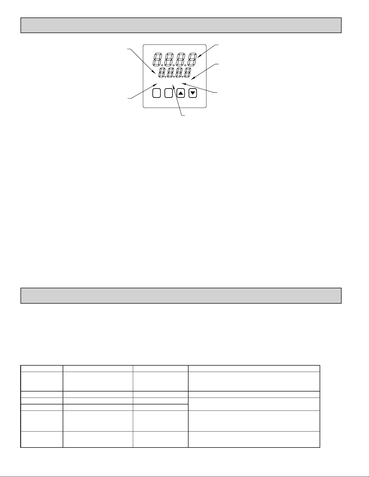
3.0 FRONT PANEL DESCRIPTION
SECONDARY DISPLAY-
MAIN DISPLAY-
DISPLAYS THE LIMIT SETPOINT.
ALSO DISPLAYS MNEMONIC OR
NUMERIC VALUE WHEN
MODIFYING A PARAMETER.
EX OUTA1A2
ILLUMINATES WHEN THE
PROCESS TEMPERATURE
EXCEEDS THE LIMIT
SETPOINT.
PR
The front panel bezel material is flame and scratch resistant, tinted plastic that
meets NEMA 4X/IP65 requirements, when properly installed. Continuous
exposure to direct sunlight may accelerate the aging process of the bezel. The
bezel should be cleaned only with a soft cloth and neutral soap product. Do NOT
use solvents. There are two 4-digit LED displays, a red upper Main Display and
a lower green Secondary Display.
There are up to four panel annunciators, with red backlighting, that illuminate
to inform the operator of the CN63500 and output status. See the front panel
diagram for a description of the annunciators. Four front panel buttons are used
to access different modes and parameters. The following is a description of each
button.
Do NOT use tools of any kind (screwdrivers, pens, pencils, etc) to operate the
keypad of this unit.
Button Functions
R - The Reset (R) button is used to reset the limit and alarm relays. The limit output
cannot be reset until the process temperature returns to the proper operating
range. Latched alarms can be reset regardless of limit exceed condition.
P - The Parameter (P) button is used to access programming, enter the change,
and scroll through the available parameters in any mode.
UP, DN - The Up/Down buttons are used to modify parameters.
CN63500 POWER-UP
Upon applying power, the CN63500 delays input indication and control
action for five seconds to perform several self-diagnostic tests and to display
basic CN63500 information. Initially, the CN63500 illuminates both displays
and all annunciators to verify that all display elements are functioning. The
CN63500 then displays the programmed input sensor type in the main (top)
DISPLAYS THE PROCESS TEMPERATURE.
ALSO DISPLAYS MNEMONIC OF SELECTED
PARAMETER IN A CONFIGURATION MODULE.
ILLUMINATES WHEN ALARM 2 IS ON.
ILLUMINATES WHEN ALARM 1 IS ON.
ILLUMINATES WHEN THE LIMIT OUTPUT IS DE-ENERGIZED.
display and the revision number of the CN63500’s operating system in the
secondary (bottom) display. The CN63500 checks for correct internal operation
and displays an error message (E-xx) if an internal fault is detected. (See the
Troubleshooting section for further information.)
Upon completion of this sequence, the CN63500 begins displaying the input
value and setpoint, and updates the outputs based upon this condition.
CN63500 CONFIGURATION OVERVIEW
The CN63500 is programmed with certain parameter settings from the
factory. Factory settings are listed in parentheses in the various Configuration of
Parameters tables. In many cases, these settings must be changed to the
particulars of the application before proper operation can be started.
The CN63500 is typically in the Normal Display Mode. In this mode, the
process temperature is displayed in the main (top) display, and the limit setpoint
is displayed in the secondary (bottom) display. When changes to the parameter
configurations are needed, the P button is pressed, and the CN63500 will enter
into the Parameter Mode.
PARAMETER CONFIGURATION BASIC STARTUP
For basic start-up, it is important to verify or change Input Parameter Module
(1-IN) parameters tYPE and SCAL, and Output Parameter Module (2-OP)
parameter LiAC (Limit Trip Action). For alarm set-up, it is important to verify or
change Alarms Parameter Module (4-AL) parameters ACt1, AL-1, ACt2, and AL-2.
If the above Input parameters or the input wiring connections are not correct,
then the main (top) display may display an error message or incorrect value.
Verify the input programming and wiring. (If incorrect display continues, refer
to the Troubleshooting section.) All other parameter configurations are important
but will not prevent the CN63500 from showing a correct display.
4.0 PARAMETER MODE
The Parameter Mode is accessed by pressing the P Button from the
Normal Display Mode. While in the Parameter Mode, the temperature is
displayed in the main (top) display, and the parameter is displayed in the
secondary (bottom) display. The correct password must be entered before any
parameters can be accessed. To modify values, use the UP or DOWN button
while the parameter is displayed. Use the P button to accept the new value, and
to scroll through the parameters. The CN63500 will automatically return to the
normal display mode if no action is taken. The CN63500 responds to the new
Parameter Mode Reference Table
DISPLAY PARAMETER RANGE DESCRIPTION
PASS Password to access parameters 0 to 250 If an incorrect value is entered, the CN63500 will display “End”
SP Limit setpoint -999 to 9999 Range limited by SPLO & SPHI.
AL-1 * Alarm #1 -999 to 9999
AL-2 * Alarm #2 -999 to 9999
CNFP
End
* Model Number Dependent.
Configuration parameter modules
End of Parameter Mode
“Up” button: enter
configuration modules.
values immediately, but the change is not committed to non-volatile memory
until the CN63500 is returned to the Normal Display Mode. If power loss occurs
before returning to the normal display mode, the new values must be re-entered.
To gain access to the Configuration Parameter Modules continue to CNFP
and press the UP button. These modules allow access to the fundamental set-up
parameters of the CN63500. If the setpoint or alarm values are modified, the
CNFP step will be skipped.
momentarily, and then return to the normal display mode. The
default password is 10. The wildcard password is 222 (in case the
password is forgotten).
The Alarm parameters can be independently locked out from
appearing. See Configuration Module 3, Parameter Lock-outs.
These modules allow access to the fundamental set-up parameters
of the CN63500. The modules are grouped into related
programming steps, such as inputs, outputs, alarms, etc. Upon
completion of each module, the program returns to “CNFP”.
When the parameter list has been scrolled through, the CN63500
will display “End” momentarily, and then return to the normal
display mode.
6
Page 7
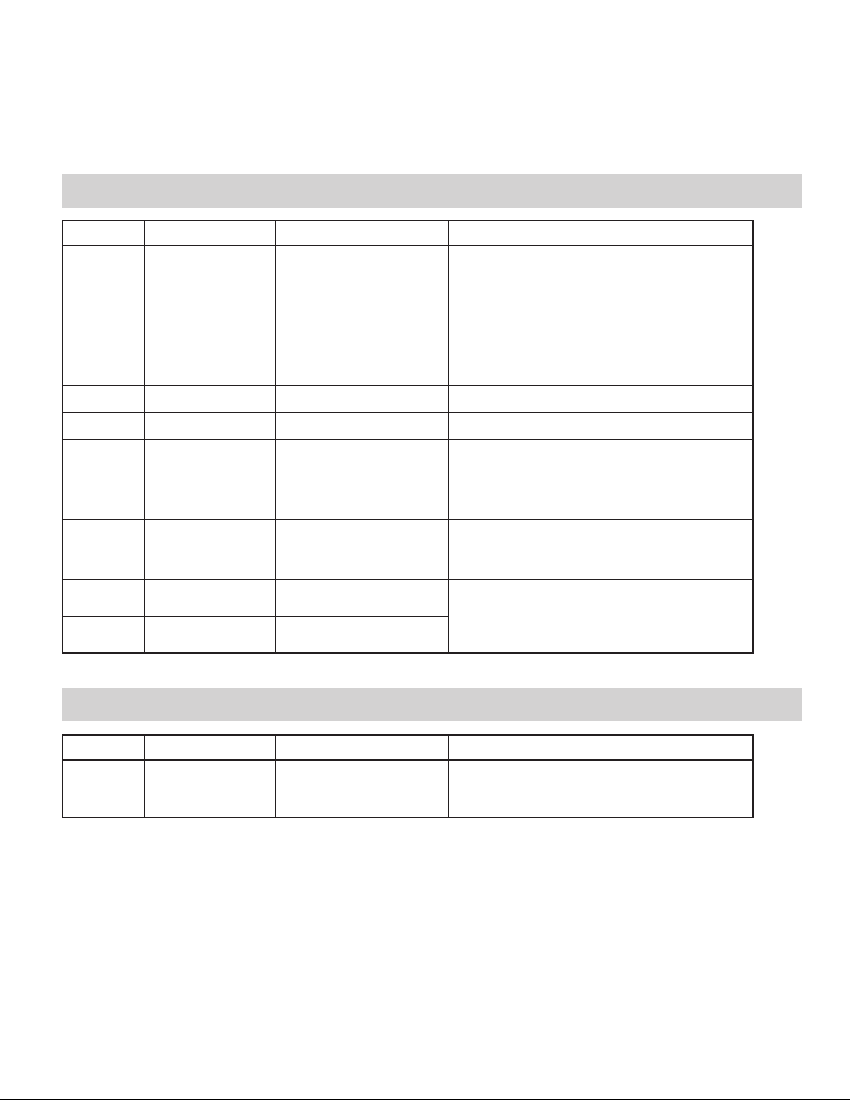
CONFIGURATION PARAMETER MODULES
The Configuration Parameter modules are accessed by pressing the UP button
from CNFP in the Parameter Mode. The UP or DOWN buttons can be pressed to
move to the desired Parameter Module. The P button is then pressed to enter into
that module. The main (top) display will be the parameter, and the secondary
(bottom) display will be the parameter value. The UP or DOWN buttons are used
to modify the desired parameter value, and the P button enters the new value, and
moves to the next parameter. The CN63500 responds to the new values after the
P button is pressed, however, the change is not committed to permanent memory
until the CN63500 is returned to the Normal Display Mode. If power loss occurs
before returning to the Normal Display Mode, the new values must be entered
again. At the end of each module, the CN63500 will go back to CNFP. Other
Parameter Modules can be accessed by pressing the UP or DOWN buttons, or
pressing P will return to the Normal Display Mode.
Parameters that are model number, or program dependent will only be
displayed when the appropriate options are installed or programmed.
CONFIGURE MODULE 1 - INPUT PARAMETERS (1-IN)
DISPLAY PARAMETER
tYPE Input Type tc-t - Type T TC
SCAL Temperature Scale °F or °C
dCPt Temperature Resolution 0 or 0.0
FLtr Digital Input Filtering and
SHFt Input Signal Shift
SPLO Limit Setpoint Lower Limit -999 to 9999
SPHI Limit Setpoint Upper Limit -999 to 9999
Display Update
(correction offset)
4 - most input filtering and slower 500
msec display update rate (outputs still
RANGE
(FACTORY SETTING)
tc-E - Type E TC
tc-J - Type J TC
tc-K - Type K TC
tc-r - Type R TC
tc-S - Type S TC
tc-b - Type B TC
tc-N - Type N TC
LIN - Linear mV
r385 - 385 curve RTD
r392 - 392 curve RTD
rLIN - Linear ohms
(tc-J)
(°F)
(0)
0 to 4
0 - least input filtering
3 - most input filtering
update at 100 msec rate)
(1)
-999 to 9999
1 or 0.1 degree
(0)
1 or 0.1 degree
(0)
1 or 0.1 degree
(9999)
DESCRIPTION/ COMMENTS
Select from the list of various thermocouple and RTD sensors.
Select either degrees Fahrenheit (F) or degrees Celsius (C). If
changed, be sure to check all parameters.
Select either 1 or 0.1 degree resolution. If changed, be sure to
check all parameters.
Select the relative degree of input signal filtering and display update
rate. The filter is an adaptive digital filter that discriminates between
measurement noise and actual process changes. Therefore, the
influence on step response time is minimal. If the signal is varying
too greatly due to measurement noise, increase the filter value.
Conversely, if the fastest CN63500 response is desired, decrease
the filter value.
If the CN63500 temperature disagrees with a reference temperature
instrument or if the temperature sensor has a known calibration, the
CN63500 temperature can be compensated by a correction offset.
The following equation expresses the relationship: Desired Display
Temp = (CN63500 Temp) + SHFt. Normally set to 0.
The CN63500 has programmable high and low setpoint limit values
to restrict the setting range of the limit setpoint. Set the limit values
so that the temperature setpoint value cannot be set outside the
safe operating area of the process. SPHI must be above SPLO.
CONFIGURE MODULE 2 - OUTPUT PARAMETERS (2-OP)
DISPLAY PARAMETER
LiAc Limit Output Trip Action LO - Low Acting
RANGE
(FACTORY SETTING)
HI - High Acting
(HI)
DESCRIPTION/ COMMENTS
The limit output is selectable for high or low trip activation. If the
process temperature goes above the limit setpoint for a high trip, or
below the limit setpoint for a low trip, the limit relay will de-energize
to initiate a process shutdown. See the Limit Output Action section
for details.
7
Page 8
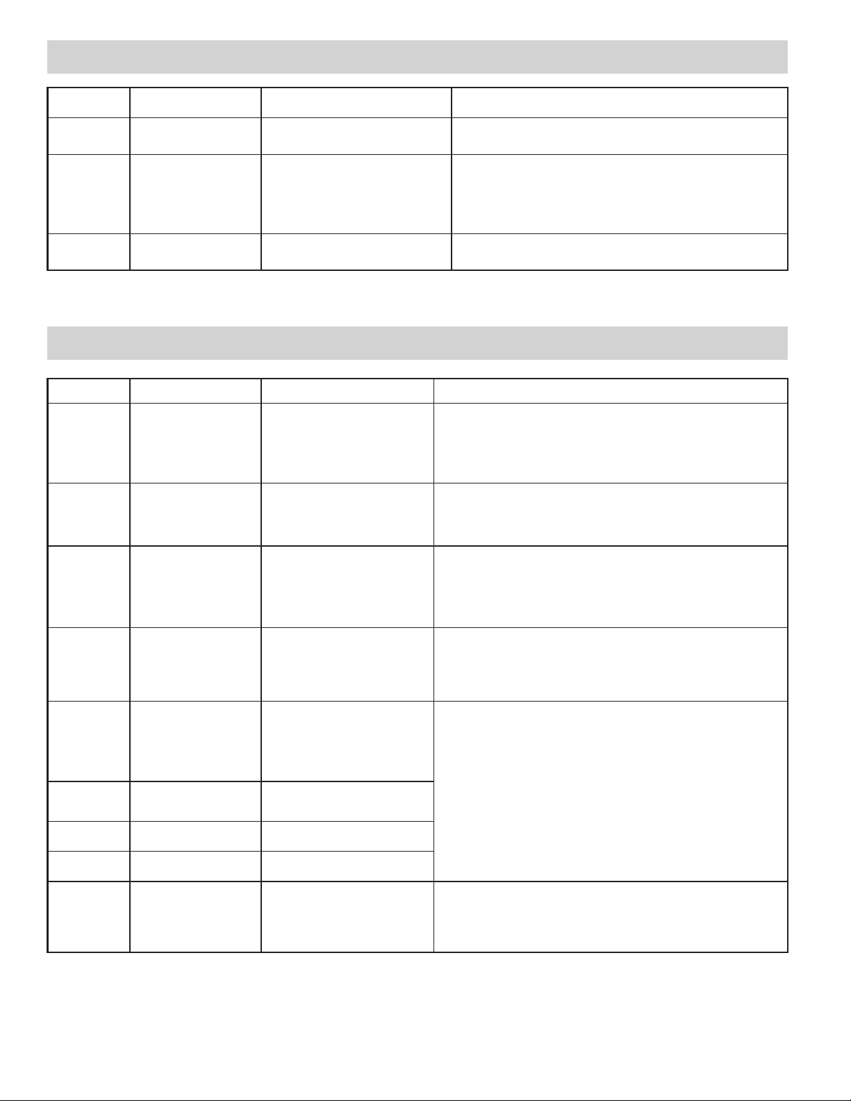
CONFIGURE MODULE 3 - LOCkOUT PARAMETERS (3-LC)
DISPLAY PARAMETER DESCRIPTION/ COMMENTS
PASS Password 0 to 250
AL * Alarms #1 and #2 access
FPrS Front panel reset NO - disabled
level
LOC - lockout, prevents the alarms from
rEd - read only, alarms appear, but
Ent - enter, alarms appear, and can be
RANGE
(FACTORY SETTING)
(10)
appearing
cannot be modified
modified
(Ent)
YES - active
(YES)
The password is required to access all parameters. The password can be
set to any value between 0 and 250. A wildcard password, 222, can be
used as an alternative to the programmed password.
The alarm(s) parameter in the Parameter Mode can be configured to be
completely locked out, read only, or fully accessible.
The front panel R button can be enabled or disabled. The Remote Reset
input is not affected by this setting.
* Model Number Dependent.
CONFIGURE MODULE 4 - ALARMS PARAMETERS (4-AL)
DISPLAY PARAMETER
Act1 Alarm 1 action mode A-HI - absolute high
rSt1 Alarm 1 reset mode Auto - automatic
Stb1 Alarm 1 standby function
AL-1 Alarm 1 value -999 to 9999
Act2 * Alarm 2 action mode The Alarm 2 parameters are programmed independently of alarm 1. See the
rSt2 * Alarm 2 reset mode Auto - automatic
Stb2 * Alarm 2 standby function
AL-2 * Alarm 2 value -999 to 9999
AHYS Alarm hysteresis value 1 to 250
(delay)
(delay)
RANGE
(FACTORY SETTING)
A-LO - absolute low
d-HI - deviation high
d-LO - deviation low
b-IN - band inside
b-Ot - band outside
(A-HI)
LATC - manual reset
(Auto)
NO or YES
(NO)
(0)
A-HI - absolute high
A-LO - absolute low
d-HI - deviation high
d-LO - deviation low
b-IN - band inside
b-Ot - band outside
(A-HI)
LATC - manual reset
(Auto)
NO or YES
(NO)
(0)
(1)
DESCRIPTION/ COMMENTS
When deviation low-acting with positive alarm value (d-LO), deviation highacting with negative value (d-HI), or band inside-acting (b-IN) is selected for the
alarm action, the indicator is OFF when the alarm output is ON. See the Alarms
section for complete details of each action. If changed, check alarm values.
Automatic reset alarms are reset by the CN63500 when the alarm condition
clears. Latched alarms require operator action to reset the alarm condition. The
front panel R button, if enabled, can be used to reset a latched alarm (see
FPrS in Configure Module 3). A latched alarm condition may also be reset via
the Remote Reset input. See the Reset Action diagram in the Alarms section.
The alarm(s) may be independently configured to exhibit a power-on, standby
delay which suppresses the alarm output from turning ON until the temperature
first stabilizes outside the alarm region. After this condition is satisfied, the alarm
standby delay is canceled and the alarm triggers normally, until the next
CN63500 power-on. This feature also works for deviation and band alarms when
the setpoint is changed via keypad. This action suppresses “nuisance” alarms.
See the Alarm Standby diagram in the Alarms section.
The alarm values are either absolute values, or relative to the limit setpoint value
(deviation and band alarms). An absolute alarm value is the value that is entered
for the alarm. A relative alarm value is the mathematical sum of the temperature
limit setpoint value and the alarm value (positive or negative), thus a relative
alarm tracks the limit setpoint value as it is changed. If the alarm action is set as
a Band Alarm, then only a positive alarm value can be entered.
corresponding Alarm 1 parameter for description.
The alarm value(s) have a programmable hysteresis band to prevent alarm
output chatter near the alarm trigger point. The hysteresis value should be set
to eliminate this effect. A value of 2 to 5 is usually sufficient for most
applications. A single alarm hysteresis value applies to both alarms. See the
Alarm Action Figures, in the Alarms section, for the effect of hysteresis on the
various alarm types.
* Model Number Dependent.
8
Page 9
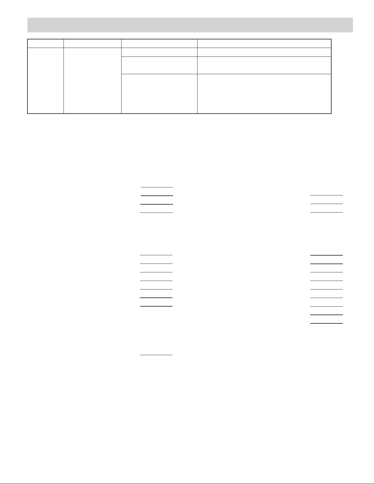
CONFIGURE MODULE 9 - FACTORy SERvICE OPERATIONS (9-FS)
DISPLAY PARAMETER RANGE DESCRIPTION/ COMMENTS
CodE Factory service function
code
USER PARAMETER VALUE CHART
CN63500 Number _____________
48 - Calibrate instrument CN63500 calibration. Refer to the Calibration section for details.
66 - Reset parameters to factory
settings
77 (twice in succession) -
Reset CN63500 calibration to
nominal values
Entering code 66 restores all parameters to factory settings. The
unit indicates the operation after the P button is pressed, by
displaying “rSEt” in the lower display momentarily.
Caution: this operation erases the CN63500 calibration values and
defaults the values to nominal settings. Reading errors of ±10%
may result. Do not perform this operation unless the CN63500 has
lost calibration. Loss of calibration is signaled by an “E-CL” error
flag at power-up. To clear this flag, perform calibration procedure
as noted in the Calibration section. Alternatively, “stepping” through
one of the calibration procedures clears the error flag, but does
NOT validate the calibration accuracy in any manner.
MNEMONIC PARAMETER USER SETTING
Password
Limit Setpoint
Alarm 1 Value
Alarm 2 Value
Input Parameters
MNEMONIC PARAMETER USER SETTING
Input Sensor Type
Temperature Scale Units
Temperature Resolution
Digital Filtering
Input Offset
Limit Setpoint Lower Limit
Limit Setpoint Upper Limit
Output Parameters
MNEMONIC PARAMETER USER SETTING
Lockout Parameters
MNEMONIC PARAMETER USER SETTING
Password
Alarm(s) Access Level
Front Panel Reset
Configure Alarm Parameters
MNEMONIC PARAMETER USER SETTING
Alarm 1 Action Mode
Alarm 1 Reset Mode
Alarm 1 Standby Enabled
Alarm 1 Value
Alarm 2 Action Mode
Alarm 2 Reset Mode
Alarm 2 Standby Enabled
Alarm 2 Value
Alarm Hysteresis Value
Limit Output Trip Action
9
Page 10
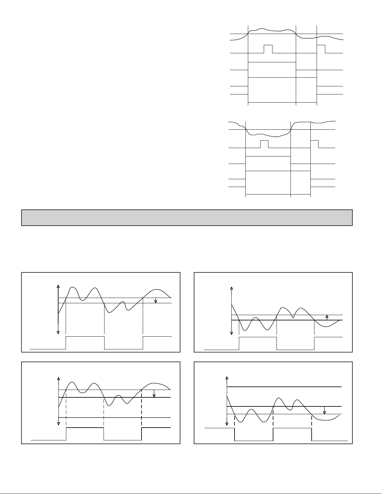
LIMIT OUTPUT ACTION
The limit output is selectable for high or low trip activation. If the process
temperature goes above the limit setpoint for a high trip, or below the limit
setpoint for a low trip, the limit relay will de-energize to initiate a process
shutdown. The limit output cannot be reset until the process temperature returns
to the proper operating range; manual reset is required. The following action
figures describe the status of the limit output and the front panel indicators for
various over/under setpoint, and reset conditions. Reset is either by the front
panel R button, if enabled, or by the Remote Reset input, terminal #6. Refer to
Configure Module 2 - Output Parameters for details of configuring the limit
output. Refer to Configure Module 3 - Lockout Parameters for details of
configuring the front panel Reset button.
High Trip Action
Setpoint
Process Temp
OFF
Reset
EXceed
OUT
Limit
Output
OFF
OFF
Energized
Annunciator
Annunciator
Low Trip Action
Process Temp
Setpoint
ON
ON
ON
De-energized
OFF
ON
OFF
OFF
Energized
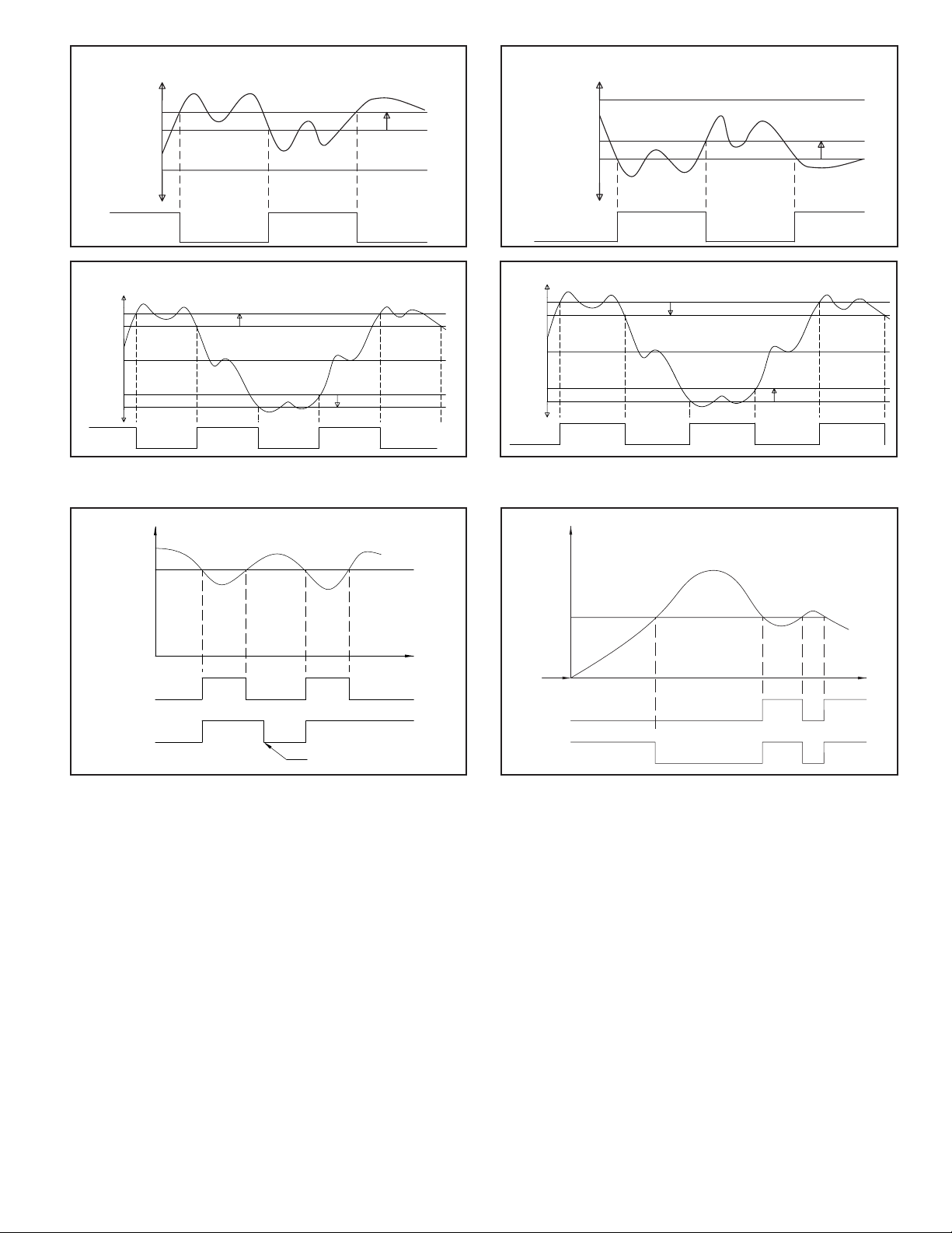
5.0 ALARMS (OPTIONAL)
The alarm action figures describe the status of the alarm output and the front
panel indicator for various over/under temperature conditions. The alarm output
wave form is shown with the output in the automatic reset mode. Select the
alarm action with care -- in some configurations, the front panel indicator (LED)
ABSOLUTE HIGH-ACTING ALARM (A-HI)
TEMP
AL
HYS
Reset
EXceed
Annunciator
OUT
Annunciator
Limit
Output
OFF
OFF
OFF
Energized
ON ON
OFF
ON
ON
De-energized
OFF
OFF
Energized
might be OFF while the output is ON. Refer to Configure Module 4 - Alarm
Parameters for details of configuring the alarms.
ABSOLUTE LOW-ACTING ALARM (A-LO)
TEMP
AL
HYS
OUTPUT OFF
LED OFF
DEVIATION HIGH-ACTING WITH POSITIVE ALARM VALUE (d-HI)
SP + AL
SP
OUTPUT OFF
LED OFF
INPUT
OUTPUT ON
LED ON
OUTPUT ON
LED ON
OUTPUT OFF
LED OFF
OUTPUT OFF
LED OFF
OUTPUT ON
LED ON
HYS
OUTPUT ON
LED ON
10
OUTPUT OFF
LED OFF
OUTPUT ON
LED ON
OUTPUT OFF
LED OFF
DEVIATION HIGH-ACTING WITH NEGATIVE ALARM VALUE (d-HI)
INPUT
SP
SP + (-AL)
OUTPUT ON
LED OFF
OUTPUT OFF
LED ON
OUTPUT ON
LED OFF
OUTPUT ON
LED ON
HYS
OUTPUT OFF
LED ON
Page 11
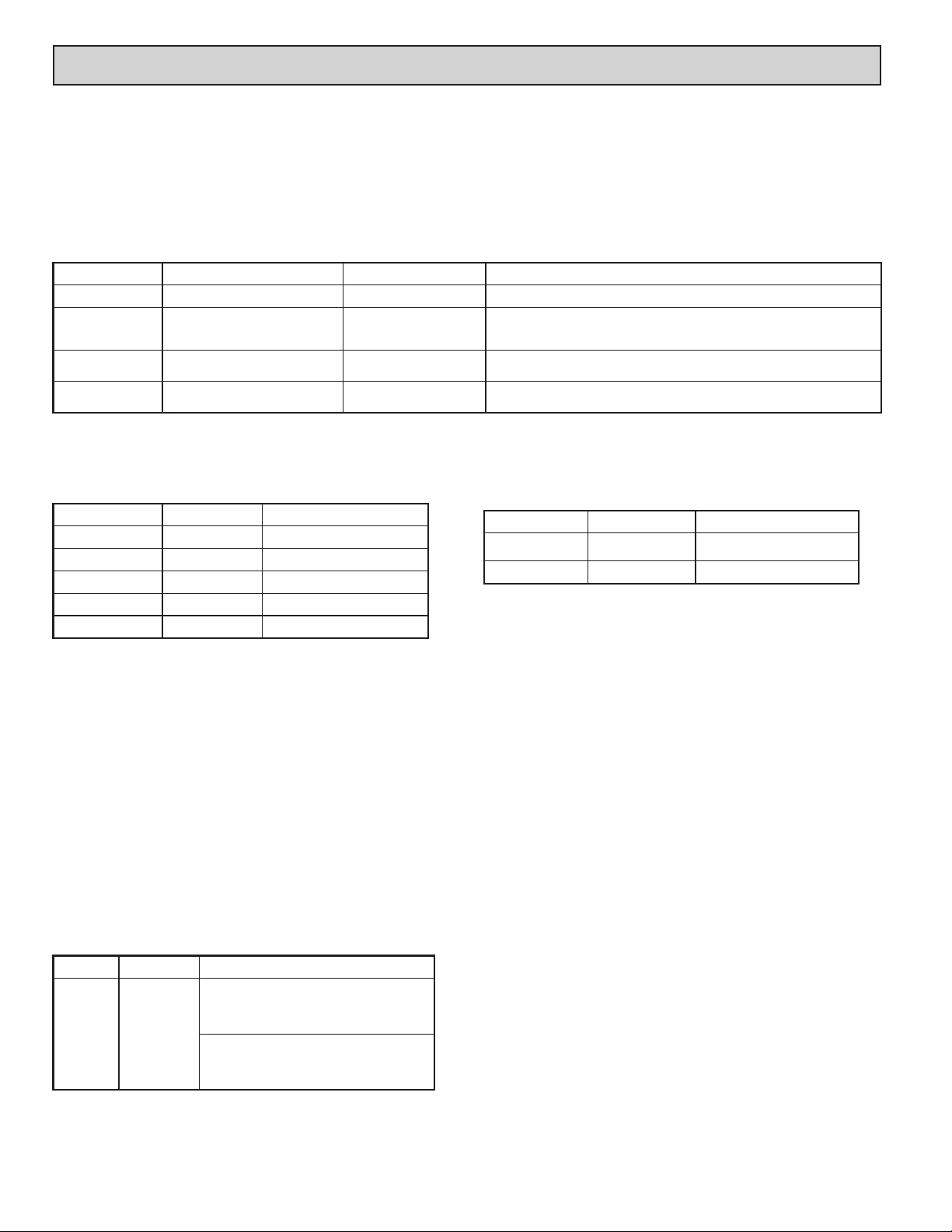
DEVIATION LOW-ACTING WITH POSITIVE ALARM VALUE (d-LO)
INPUT
SP + AL
SP
HYS
DEVIATION LOW-ACTING WITH NEGATIVE ALARM VALUE (d-LO)
INPUT
SP
SP + (-AL)
HYS
OUTPUT OFF
LED ON
BAND INSIDE ACTING (b-IN)
LED ON
OUTPUT ON
LED OFF
SP + AL
SP
SP - AL
OUTPUT ON
LED OFF
OUTPUT ON
LED OFF
INPUT
OUTPUT OFF
Alarm Reset Sequence
INPUT
(ABSOLUTE LOW ACTING SHOWN)
ALARM VALUE
AUTOMATIC
RESET
MANUAL
RESET
OFF
OFF
OUTPUT ON
LED OFF
HYS
HYS
ON
OUTPUT OFF
LED ON
ALARM MODE
OFF
OUTPUT ON
LED OFF
ON
ON OFF ON
MANUAL RESET
PERFORMED BY OPERATOR
OUTPUT OFF
LED ON
OUTPUT OFF
LED ON
OFF
TIME
OUTPUT ON
LED ON
BAND OUTSIDE ACTING (b-Ot)
HYS
OUTPUT OFF
LED OFF
OUTPUT ON
INPUT
SP + AL
SP
SP - AL
OUTPUT OFF
LED OFF
OUTPUT OFF
LED OFF
OUTPUT ON
LED ON
Alarm Standby Delay Sequence
ALARM VALUE
UNIT
POWER-ON
STANDBY
ENABLED
STANDBY
DISABLED
INPUT
ON OFFONOFF ON
ALARM MODE
(ABSOLUTE LOW ACTING
W/AUTO-RESET SHOWN)
OFF ON OFFON
OUTPUT OFF
LED OFF
LED ON
HYS
OUTPUT OFF
LED OFF
OUTPUT ON
LED ON
OUTPUT ON
LED ON
TIME
CALIBRATION CHECKS
The instrument has been fully calibrated at the factory for all input types. If
the unit appears to be indicating or controlling incorrectly, see the Troubleshooting
section before attempting this procedure.
If the CN63500 is suspected of reading incorrectly, the instrument may be
checked for indication accuracy without disturbing the factory calibration. The
following procedures may be used for this purpose.
Note: Allow ½ hour warm-up before checking these parameters.
mV Reading Check
1. Connect a DC mV source with an accuracy of 0.03% or better to terminal #8
(-) & #9 (+).
2. Configure Input Parameters Module 1 for linear mV (Lin) input, under tYPE.
3. Compare the CN63500 read-out to the standard at various points over the range
(-5.00 mV to 56.00 mV). The tolerance is ±(0.15% of reading + 1 LSD).
4. Calibrate the CN63500 if the readings are out of tolerance.
Thermocouple Cold Junction Temperature Check
1. Connect a thermocouple probe of known accuracy (Types T, E, J, K, N only)
to CN63500. Select the probe used in Configure Module 1.
2. Connect a reference temperature probe to measuring end of thermocouple to
monitor temperature. Allow sufficient time for temperatures to equalize.
3. Compare CN63500 display with reference temperature probe. The CN63500
display should equal the calibrated probe temperature. (Tolerance is ±1ºC.)
4. Calibrate the cold junction temperature if out of tolerance.
RTD Ohms Reading Check
1. Connect RTD simulator (with an accuracy of 0.1 ohm or better) capable of
operating with less than 150 µA to terminals #8, #9, & #10.
2. Configure Input Parameters Module 1 for linear ohms (rLin) input, under tYPE.
3. Compare the CN63500 read-out with the RTD simulator at various points over
the range 2.0 to 300.0 ohms. The tolerance is ±(0.3% of span + 1 LSD).
4. Calibrate the CN63500 RTD ohms if out of tolerance.
Error Flag E-CL
If error flag “E-CL” appears at power-up, a loss of calibration parameters due
to noise spikes has occurred. Entering code 77 twice in Factory Service
Operations Module (9-FS) erases the CN63500 calibration values and defaults
the values to nominal settings. Reading errors of ±10% may result. It is
recommended that the CN63500 be fully recalibrated. If using thermocouple
only, the RTD calibration need not be performed.
Note: the “E-CL” flag may be cleared by “stepping” through cold junction
calibration procedure without the need to change any calibration values. A
±10% reading error will still exist.
11
Page 12
6.0 CALIbRATION
When re-calibration is required (generally every two years), this procedure
should be performed by qualified technicians using appropriate equipment.
Equipment source accuracy of 0.03% or better is required.
The procedure consists of: applying accurate mV signals, setting the
thermocouple cold junction temperature, and applying precision resistance,
among others. Allow a 30 minute warm-up period before starting this procedure.
Do not use thermocouple wire for the millivolt or RTD ohms calibration.
Factory Service Operations - Calibration (9-FS)
CodE
CAL
CJC
Enter function code
Millivolt calibration
Thermocouple cold junction
temperature calibration
48
yes/no
yes/no
yes/noRTD resistance calibrationrtd
Millivolt Calibration (CAL)
Connect precision millivolt source with an accuracy of 0.03% to terminals #8
(-) & #9 (+). Cold Junction or RTD ohms calibration MUST be performed after
millivolt calibration.
DESCRIPTION/ COMMENTSACTIONDISPLAY
StP2
StP4
StP5
Apply 0.0 mVStP1
Apply 42.0 mV
Apply 56.0 mV
Wait 10 seconds, press P.
Wait 10 seconds, press P.Apply 14.0 mV
Wait 10 seconds, press P.Apply 28.0 mVStP3
Wait 10 seconds, press P.
Wait 10 seconds, press P.
This procedure may be aborted by disconnecting power to the CN63500
before exiting the configuration mode. The existing calibration settings remain
in affect.
Note: After completing any of the calibration sequences, the CN63500 defaults
the input sensor type to thermocouple type “J” (tc-J). Be sure to set input
sensor for proper type.
Note: The CN63500 must be restored to normal display mode before any data
is stored.
DESCRIPTION/ COMMENTSRANGEPARAMETERDISPLAY
Calibrate instrument.
Calibration required for both RTD and TC input. If this procedure is performed,
the cold junction temp or RTD ohms calibration procedures in turn must be
completed.
Not required if only using RTD input. This procedure can only be performed
AFTER an accurate mV calibration.
Not required if only using TC input. This procedure can only be performed
AFTER an accurate mV calibration.
RTD Ohms Calibration (RTD)
This procedure must be performed AFTER an accurate mV calibration.
Connect one leg of precision resistance (accuracy of 0.1 ohm) to terminals #9
and #10 together, and the other leg to #8.
DESCRIPTION/ COMMENTSACTIONDISPLAY
Connect 0.0 ohm
(jumper wire)
Connect 277.0 ohm
Wait 10 seconds, press P.Rtd1
Wait 10 seconds, press P.Rtd2
Thermocouple Cold Junction Calibration (CJC)
This procedure must be performed AFTER an accurate mV calibration.
1. Exit Factory Service Operations (continually press P until “End”), and return
to Normal Display Mode.
2. Connect a thermocouple probe of known accuracy to the CN63500 (Types T,
E, J, K, and N only). Select the probe type used in Configure Module 1.
3. Connect a reference temperature probe to the measuring end of the CN63500
thermocouple probe. The two probes should be shielded from air movement
and allowed sufficient time to equalize in temperature. (As an alternative, the
CN63500 thermocouple probe may be placed in a calibration bath of known
temperature.)
4. Compare CN63500 display with reference temperature probe (or calibration
bath). If the displayed CN63500 temperature does not equal the reference
probe temperature, calculate the CJ error as follows:
CJ Error = reference probe temperature - displayed CN63500 temperature
5. Enter Factory Service Operations Module (9-FS).
DESCRIPTION/ COMMENTSPARAMETERDISPLAY
Observe the indicated cold junction
temperature. Add the calculated CJ Error to the
displayed value. Enter the sum as the new
CJC
Cold Junction
Temperature
value for CJC. Exit 9-FS and repeat step 4.
Note: If the initial value for CJC is not within
the range of 15°C to 40°C, enter 25.0° for
CJC and repeat the Cold Junction Calibration
procedure.
12
Page 13
7.0 TROUbLESHOOTING
The majority of problems can be traced to improper connections or incorrect
set-up parameters. Be sure all connections are clean and tight, that the correct
For further technical assistance, contact technical support at the appropriate
company numbers listed.
output board is fitted, and that the set-up parameters are correct.
PROBLEMS POSSIBLE CAUSE
NO DISPLAY 1. Power off.
CN63500 NOT WORKING 1. Incorrect parameter set-up. 1. Check set-up parameters.
“E-FP” IN DISPLAY 1. Defective front panel button. 1. Press R to escape, then check all buttons for proper operation.
“E-UP” IN DISPLAY 1. Internal problem with CN63500. 1. Replace unit.
“E-E2” IN DISPLAY 1. Loss of setup parameters due to noise spike or
“E-CL” IN DISPLAY 1. Loss of calibration parameters due to noise
“...” or “-..” IN DISPLAY
“OPEN” IN DISPLAY 1. Probe disconnected.
“OLOL” IN UPPER DISPLAY
“ULUL” IN UPPER DISPLAY 1. Input is below range of CN63500.
“OLOL” OR “ULUL” IN LOWER
DISPLAY
2. Brown-out condition.
3. Loose connection or improperly wired.
4. Bezel assembly not fully seated into rear of
CN63500.
other EMI event.
spike or other EMI event.
1. Display value exceeds display range.
2. Defective or mis-calibrated cold junction circuit.
3. Loss of set-up parameters.
4. Internal malfunction.
2. Broken or burned-out probe.
3. Corroded or broken terminations.
4. Excessive process temperature.
1. Check input parameters.
2. Change to input sensor with a higher
temperature range.
3. Replace transmitter or probe.
4. Reduce temperature.
5. Perform input calibration.
2. Temperature below range of input probe.
3. Defective or incorrect transmitter or probe.
4. Excessive low temperature for probe.
5. Loss of setup parameters.
1. Signal input exceeds allowable range by 5%. 1. Check remote signal source.
1. Check power.
2. Verify power reading.
3. Check connections.
4. Check installation.
2. Replace unit.
1. Press R to escape, then check all set-up parameters.
a. Check sensor input and AC line for excessive noise.
b. If fault persists, replace CN63500.
1. Press R to escape, then check CN63500 accuracy.
a. Recalibrate CN63500. (See Factory Service Module code 77.)
b. Reset parameters to factory default settings.
1. Change resolution to display whole number and verify reading.
2. Perform cold junction calibration.
3. Check set-up parameters.
4. Perform Input calibration.
1. Connect probe.
2. Replace probe.
3. Check connections.
4. Check process parameters.
1. Input exceeds range of CN63500.
2. Temperature exceeds range of input probe.
3. Defective or incorrect transmitter or probe.
4. Excessive high temperature for probe.
5. Loss of setup parameters.
1. Check input parameters.
2. Change to input sensor with a lower temperature range.
3. Replace transmitter or probe.
4. Raise temperature.
5. Perform input calibration.
REMEDIES
13
Page 14
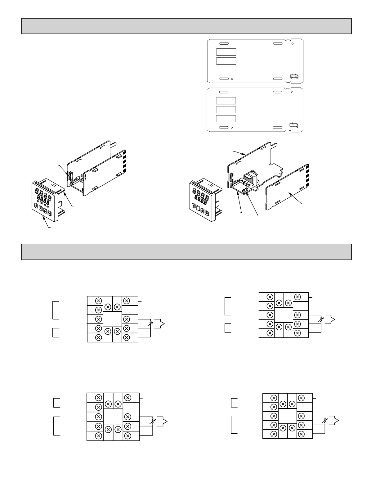
8.0 INSTALLING AN OUTPUT bOARD
D
REMOTE
REMOTE
The CN63500 is supplied with an output board installed.
Replacing Output Board
1. Remove the bezel assembly.
2. Lift up on the top bezel board latch while gently pulling out on the bezel/
display board assembly. Do NOT remove the display board from the bezel.
3. Remove the output board by pulling it away from the other boards. Replace
the output board by aligning the board to board connector. Be certain the
connector is fully mated.
4. Connect the bezel/ display board assembly by guiding the board ends into the
bezel latches. Slide the assembly on evenly until the display board connector
is completely engaged and bezel latches are fully seated onto the boards.
AL1
LIMIT
AL2
AL1
LIMIT
Form-C Relay
Output Board
#CN6-RBDLA210
Form-A Relay
Output Board
#CN6-RBD48111
DISPLAY
BOARD
CONNECTOR
BEZEL BOARD
LATCH
BEZEL/DISPLAY
BOARD ASSEMBLY
CPU BOARD
EX
A2A1OUT
P
POWER
SUPPLY
BOARD
EB0784
MD1797
OUTPUT BOARD
CONNECTOR
9.0 TERMINAL CONFIGURATIONS
AC Models
Form-A Limit Relay with 2 Alarms Form-A Limit Relay with 2 Alarms
ALARM
RELAYS
LIMIT
RELAY
A2 N.O.
COMM.
A1 N.O.
N.O.
COMM.
14
13
1
2
3
4
5
11
~
AC
12
~
AC
85-250 VAC
50/60 HZ 8VA
6
7
8
9
10
REMOTE
RESET
COMM.
TC
RTD
ALARM
RELAYS
+
LIMIT
RELAY
DC Models
A2 N.O.
COMM.
A1 N.O.
COMM.
1
2
3
N.O.
4
5
POWER
DC 18-36V 7W
AC 24V ±10%
50/60 HZ 9VA
13
11
(+)
14
12
(-)
OUTPUT BOAR
6
RESET
7
COMM.
8
9
10
TC
RTD
+
Form-C Limit Relay with 1 Alarm
13
1
ALARM 1
RELAY
LIMIT
RELAY
N.O.
COMM.
N.O.
N.C.
COMM.
2
3
4
5
11
~
AC
85-250 VAC
50/60 HZ 8VA
14
12
~
AC
6
7
8
9
10
RESET
COMM.
TC
RTD
Form-C Limit Relay with 1 Alarm
6
7
8
9
10
REMOTE
RESET
COMM.
TC
RTD
+
ALARM 1
RELAY
+
LIMIT
RELAY
N.O.
COMM.
N.C.
COMM.
POWER
2
3N.O.
4
5
11
(+)
12
(-)
14
13
1
DC 18-36V 7W
AC 24V ±10%
50/60 HZ 9VA
14
Page 15

OMEGAnet
omega.com
®
Online Service
Internet e-mail
Servicing North America:
U.S.A.: One Omega Drive, P.O. Box 4047
ISO 9001 Certified Stamford, CT 06907-0047
TEL: (203) 359-1660
FAX: (203) 359-7700
e-mail: [email protected]
Canada: 976 Bergar
For immediate technical or application assistance:
U.S.A. and Canada: Sales Service: 1-800-826-6342/1-800-TC-OMEGA
Customer Service: 1-800-622-2378/1-800-622-BEST
Engineering Service: 1-800-872-9436/1-800-USA-WHEN
®
®
Mexico: En Español: (001) 203-359-7803
It is the policy of OMEGA Engineering, Inc. to comply with all worldwide safety and EMC/EMI regulations that apply. OMEGA is constantly pursuing certification of its
products to the European New Approach Directives. OMEGA will add the CE mark to every appropriate device upon certification.
The information contained in this document is believed to be correct, but OMEGA accepts no liability for any errors it contains, and reserves the right to alter specifications without notice.
WARNING : These products are not designed for use in, and should not be used for, human applications.
Czech Republic: Frystatska 184, 733 01 Karviná, Czech Republic
Germany/Austria: Daimlerstrasse 26, D-75392 Deckenpfronn, Germany
TEL: +49 (0)7056 9398-0
FAX: +49 (0)7056 9398-29
Toll Free in Germany: 0800 639 7678
e-mail: [email protected]
United Kingdom: One Omega Drive, River Bend Technology Centre
ISO 9002 Certified Northbank, Irlam, Manchester
M44 5BD United Kingdom
TEL: +44 (0)161 777 6611
FAX: +44 (0)161 777 6622
®
Servicing Europe:
WARRANTY/DISCLAIMER
OMEGA ENGINEERING, INC. warrants this unit to be free of defects in materials and workmanship for a period of 25 months from date of purchase.
OMEGA’s WARRANTY adds an additional one (1) month grace period to the normal two (2) year product warranty to cover handling and shipping time.
This ensures that OMEGA’s customers receive maximum coverage on each product.
If the unit malfunctions, it must be returned to the factory for evaluation. OMEGA’s Customer Service Department will issue an Authorized Return (AR)
number immediately upon phone or written request. Upon examination by OMEGA, if the unit is found to be defective, it will be repaired or replaced at no
charge. OMEGA’s WARRANTY does not apply to defects resulting from any action of the purchaser, including but not limited to mishandling, improper
interfacing, operation outside of design limits, improper repair, or unauthorized modification. This WARRANTY is VOID if the unit shows evidence of having
been tampered with or shows evidence of having been damaged as a result of excessive corrosion; or current, heat, moisture or vibration; improper
specification; misapplication; misuse or other operating conditions outside of OMEGA’s control. Components in which wear is not warranted, include but
are not limited to contact points, fuses, and triacs.
OMEGA is pleased to offer suggestions on the use of its various products. However, OMEGA neither assumes responsibility for any
omissions or errors nor assumes liability for any damages that result from the use of its products in accordance with information
provided by OMEGA, either verbal or written. OMEGA warrants only that the parts manufactured by the company will be as specified
and free of defects. OMEGA MAKES NO OTHER WARRANTIES OR REPRESENTATIONS OF ANY KIND WHATSOEVER, EXPRESSED OR
IMPLIED, EXCEPT THAT OF TITLE, AND ALL IMPLIED WARRANTIES INCLUDING ANY WARRANTY OF MERCHANTABILITY AND FITNESS
FOR A PARTICULAR PURPOSE ARE HEREBY DISCLAIMED. LIMITATION OF LIABILITY: The remedies of purchaser set forth herein are
exclusive, and the total liability of OMEGA with respect to this order, whether based on contract, warranty, negligence, indemnification,
strict liability or otherwise, shall not exceed the purchase price of the component upon which liability is based. In no event shall OMEGA
be liable for consequential, incidental or special damages.
CONDITIONS: Equipment sold by OMEGA is not intended to be used, nor shall it be used: (1) as a “Basic Component” under 10 CFR 21 (NRC), used in or
with any nuclear installation or activity; or (2) in medical applications or used on humans. Should any Product(s) be used in or with any nuclear installation
or activity, medical application, used on humans, or misused in any way, OMEGA assumes no responsibility as set forth in our basic WARRANTY/
DISCLAIMER language, and, additionally, purchaser will indemnify OMEGA and hold OMEGA harmless from any liability or damage whatsoever arising out
of the use of the Product(s) in such a manner.
Direct all warranty and repair requests/inquiries to the OMEGA Customer Service Department. BEFORE RETURNING ANY PRODUCT(S) TO OMEGA,
RETURN REQUESTS/INQUIRIES
PURCHASER MUST OBTAIN AN AUTHORIZED RETURN (AR) NUMBER FROM OMEGA’S CUSTOMER SERVICE DEPARTMENT (IN ORDER TO AVOID
PROCESSING DELAYS). The assigned AR number should then be marked on the outside of the return package and on any correspondence.
The purchaser is responsible for shipping charges, freight, insurance and proper packaging to prevent breakage in transit.
FOR WARRANTY RETURNS, please have the following information
available BEFORE contacting OMEGA:
1. Purchase Order number under which the product was PURCHASED,
2. Model and serial number of the product under warranty, and
3. Repair instructions and/or specific problems relative to the product.
OMEGA’s policy is to make running changes, not model changes, whenever an improvement is possible. This affords our customers the latest in technology and
engineering. OMEGA is a registered trademark of OMEGA ENGINEERING, INC.
© Copyright 2006 OMEGA ENGINEERING, INC. All rights reserved. This document may not be copied, photocopied, reproduced, translated, or reduced to any
electronic medium or machine-readable form, in whole or in part, without the prior written consent of OMEGA ENGINEERING, INC.
FOR NON-WARRANTY REPAIRS, consult OMEGA for current repair charges.
Have the following information available BEFORE contacting OMEGA:
1. Purchase Order number to cover the COST of the repair,
2. Model and serial number of the product, and
3. Repair instructions and/or specific problems relative to the product.
Page 16

Where Do I Find Everything I Need for
Process Measurement and Control?
OMEGA…Of Course!
Shop online at omega.com
TEMPERATURE
] Thermocouple, RTD & Thermistor Probes, Connectors, Panels & Assemblies
] Wire: Thermocouple, RTD & Thermistor
] Calibrators & Ice Point References
] Recorders, Controllers & Process Monitors
] Infrared Pyrometers
PRESSURE, STRAIN AND FORCE
] Transducers & Strain Gages
] Load Cells & Pressure Gages
] Displacement Transducers
] Instrumentation & Accessories
FLOW/LEVEL
] Rotameters, Gas Mass Flowmeters & Flow Computers
] Air Velocity Indicators
] Turbine/Paddlewheel Systems
] Totalizers & Batch Controllers
pH/CONDUCTIVITY
] pH Electrodes, Testers & Accessories
] Benchtop/Laboratory Meters
] Controllers, Calibrators, Simulators & Pumps
] Industrial pH & Conductivity Equipment
DATA ACQUISITION
] Data Acquisition & Engineering Software
] Communications-Based Acquisition Systems
] Plug-in Cards for Apple, IBM & Compatibles
] Datalogging Systems
] Recorders, Printers & Plotters
HEATERS
] Heating Cable
] Cartridge & Strip Heaters
] Immersion & Band Heaters
] Flexible Heaters
] Laboratory Heaters
ENVIRONMENTAL
MONITORING AND CONTROL
] Metering & Control Instrumentation
] Refractometers
] Pumps & Tubing
] Air, Soil & Water Monitors
] Industrial Water & Wastewater Treatment
] pH, Conductivity & Dissolved Oxygen Instruments
 Loading...