

Page 1
CN63200 and CN63400
1/16 DIN Temperature and
Process Controllers
INSTRUCTION
SHEET
M4496-0613
Shop online at: omega.com e-mail: [email protected]
For latest product manuals: omegamanual.info
UL Recognized Component,
File #E123489
GENERAL DESCRIPTION
The Model CN63200 Controller accepts signals from a variety of temperature
sensors (thermocouple or RTD), while the Model CN63400 Controller accepts
either a 0 to 10 VDC or 0/4 to 20 mA DC input signal. Both controllers can
provide an accurate output control signal (time proportional or DC Analog
Output) to maintain a process at a setpoint value. Dual 4-digit displays allow
viewing of the process/temperature and setpoint simultaneously. Front panel
indicators inform the operator of the controller and output status. The
comprehensive programming allows these controllers to meet a wide variety of
application requirements.
MAIN CONTROL
The controller operates in the PID Control Mode for both heating and
cooling, with on-demand auto-tune, that establishes the tuning constants. The
PID tuning constants may be fine-tuned through the front panel and then locked
out from further modification. The controller employs a unique overshoot
suppression feature, that allows the quickest response without excessive
overshoot. Switching to Manual Mode provides the operator direct control of the
output. The controller may also be programmed to operate in On/Off mode with
adjustable hysteresis.
ALARMS
Optional alarm(s) can be configured independently for absolute high or low
acting with balanced or unbalanced hysteresis. They can also be configured for
deviation and band alarm. In these modes, the alarm trigger values track the
setpoint value. Adjustable alarm hysteresis can be used for delaying output
response. The alarms can be programmed for Automatic or Latching operation.
A selectable standby feature suppresses the alarm during power-up until the
temperature stabilizes outside the alarm region.
PID CONTROL WITH REDUCED OVERSHOOT
CN63200 ACCEPTS TC AND RTD
CN63400 ACCEPTS 0-10 V AND 0/4-20 mA SIGNALS
ON DEMAND AUTO-TUNING OF PID SETTINGS
DC ANALOG OUTPUT (OPTIONAL)
USER PROGRAMMABLE FUNCTION BUTTON
FRONT PANEL PROGRAMMING
ANALOG OUTPUT OPTION
The optional DC Analog Output (10 V or 20 mA) can be configured and
scaled for control or re-transmission purposes. The programmable output update
time reduces valve or actuator activity.
CONSTRUCTION
The controller is constructed of a lightweight, high impact, black plastic
textured case and bezel with a clear display window. The front panel meets
NEMA 4X/IP65 specifications when properly installed. In applications that do
not require protection to NEMA 4X, multiple controllers can be stacked
horizontally or vertically. Modern surface-mount technology, extensive testing,
plus high immunity to noise interference makes the controller extremely reliable
in industrial environments.
SAFETY SUMMARY
All safety related regulations, local codes and instructions that appear in the
manual or on equipment must be observed to ensure personal safety and to
prevent damage to either the instrument or equipment connected to it. If
equipment is used in a manner not specified by the manufacturer, the protection
provided by the equipment may be impaired.
Do not use the controller to directly command motors, valves, or other actuators
not equipped with safeguards. To do so can be potentially harmful to persons or
equipment in the event of a fault to the controller. An independent and redundant
temperature limit indicator with alarm outputs is strongly recommended.
CAUTION: Risk of Danger.
Read complete instructions prior to
installation and operation of the unit.
CAUTION: Risk of electric shock.
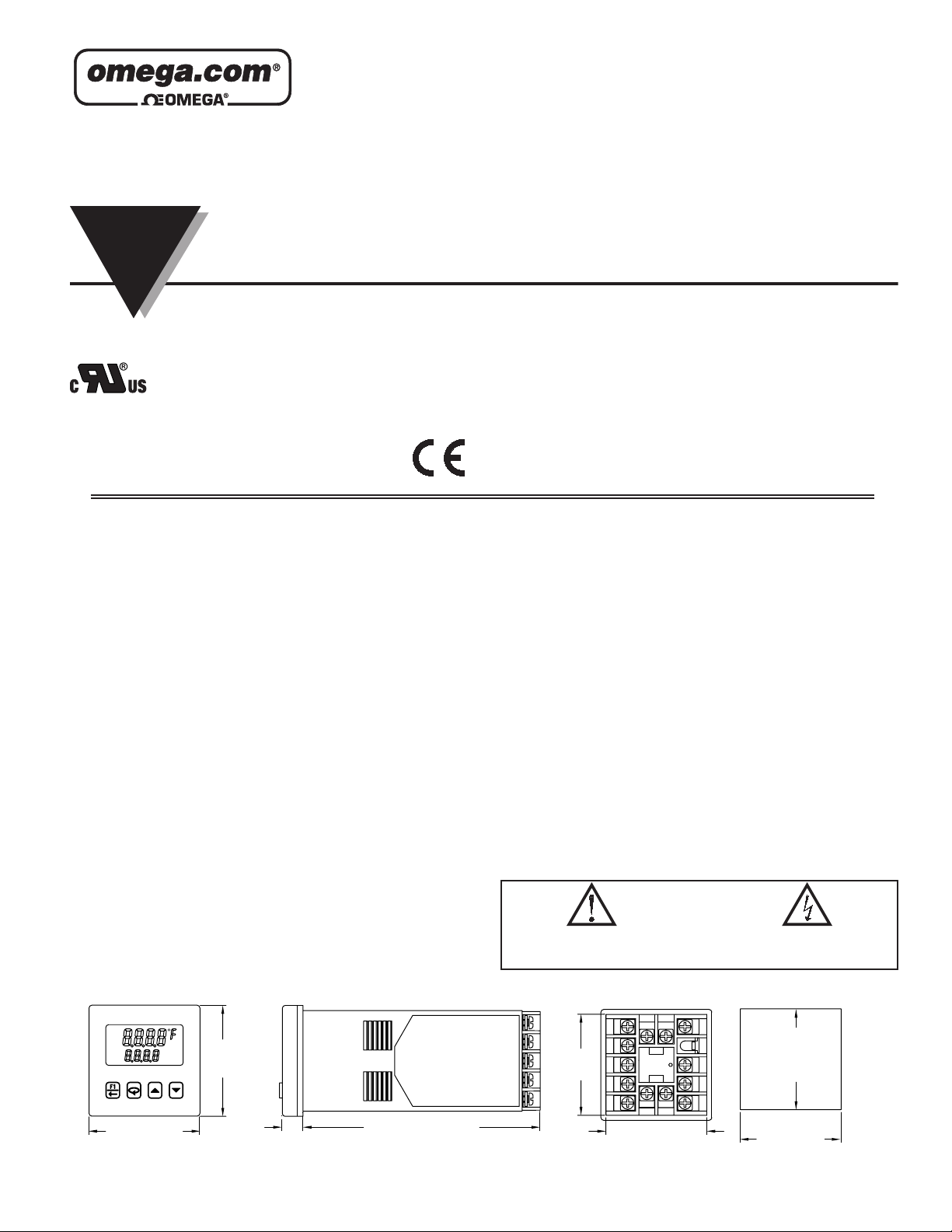
DIMENSIONS In inches (mm)
R
1
A
2
A
21OO
1.95
(49.5)
%
MA
N
%WP
1.95
(49.5)
0.37
(9.4)
4.17 (105.9)
PANEL CUT-OUT
1413
11512
1.76 (44.7)
6
7
8
9
10
1.772
(45 )
1.772
(45 )
+0.024
-0.000
+0.6
-0.0
+0.024
-0.000
+0.6
-0.0
LP0681B
1.76
(44.7)
1
2
3
4
1
Page 2

OMEGAnet
®
Online Service
omega.com
Internet e-mail
Servicing North America:
U.S.A.: One Omega Drive, P.O. Box 4047
ISO 9001 Certified Stamford, CT 06907-0047
Canada: 976 Bergar
For immediate technical or application assistance:
U.S.A. and Canada: Sales Service: 1-800-826-6342/1-800-TC-OMEGA
Customer Service: 1-800-622-2378/1-800-622-BEST
Engineering Service: 1-800-872-9436/1-800-USA-WHEN
®
®
®
Mexico: En Español: (001) 203-359-7803 e-mail: [email protected]
Servicing Europe:
Czech Republic: Frystatska 184, 733 01 Karviná, Czech Republic
Germany/Austria: Daimlerstrasse 26, D-75392 Deckenpfronn, Germany
TEL: +49 (0)7056 9398-0 FAX: +49 (0)7056 9398-29
Toll Free in Germany: 0800 639 7678
e-mail: [email protected]
United Kingdom: One Omega Drive, River Bend Technology Centre
ISO 9002 Certified Northbank, Irlam, Manchester
M44 5BD United Kingdom
TEL: +44 (0)161 777 6611 FAX: +44 (0)161 777 6622
Toll Free in United Kingdom: 0800-488-488
e-mail: [email protected]
It is the policy of OMEGA Engineering, Inc. to comply with all worldwide safety and EMC/EMI
regulations that apply. OMEGA is constantly pursuing certification of its products to the European New
Approach Directives. OMEGA will add the CE mark to every appropriate device upon certification.
The information contained in this document is believed to be correct, but OMEGA accepts no liability for any
errors it contains, and reserves the right to alter specifications without notice.
WARNING : These products are not designed for use in, and should not be used for, human applications.
2
Page 3
GENERAL SPECIFICATIONS
1. DISPLAY: 2 Line by 4-digit, LCD negative image transmissive with
backlighting.
Top (Process) Display: 0.3" (7.6 mm) high digits with red backlighting.
Bottom (Parameter) Display: 0.2" (5.1 mm) high digits with green
backlighting.
2. ANNUNCIATORS:
Status Annunciators:
O1 - Main control output is active.
O2 - Cooling output is active (when Alarm 2 is used for cooling).
A1 - Alarm 1 output is active.
A2 - Alarm 2 output is active.
°F, °C - Temperature units.
%PW - Output power percentage is shown in Bottom display.
MAN - Controller is in Manual Mode.
R - Ramping Setpoint indicator.
% - Percent indicator (CN63400 models only).
Display Messages:
- Measurement exceeds + sensor range
- Measurement exceeds - sensor range
- Open sensor is detected (CN63200 only)
- Shorted sensor is detected (RTD only)
- Measurement exceeds controller limits (CN63400 only)
- Display value exceeds + display range
- Display value exceeds - display range
3. POWER:
Line Voltage Models:
85 to 250 VAC, 50/60 Hz, 8 VA
Low Voltage Models:
DC Power: 18 to 36 VDC, 4 W
AC Power: 24 VAC, ±10%, 50/60 Hz, 7 VA
4. CONTROLS: Three rubber push buttons for modification and setup of
controller parameters. One additional button (F1) for user programmable
function. One external user input (models with alarms) for parameter lockout
or other user programmable functions.
5. MEMORY: Nonvolatile E
2
PROM retains all programmable parameters.
6. ISOLATION LEVEL:
AC power with respect to all other I/O: 250 V working (2300 V for 1 min.)
Sensor input to analog output: 50 V working (500 V for 1 minute)
Relay contacts to all other I/O: 300 V working (2300 V for 1 minute)
DC power with respect to sensor input and analog output: 50 V working
(500 V for 1 minute)
7. CERTIFICA TIONS AND COMPLIANCES:
CE Approved
EN 61326-1 Immunity to Industrial Locations
Emission CISPR 11 Class A
IEC/EN 61010-1
RoHS Compliant
UL Recognized Component: File #E123489
Type 4X Enclosure rating (Face only)
IP65 Enclosure rating (Face only)
IP20 Enclosure rating (Rear of unit)
Refer to EMC Installation Guidelines section of the bulletin for additional
information.
8. ENVIRONMENTAL CONDITIONS:
Operating Temperature Range: 0 to 50 °C
Storage Temperature Range: -40 to 80 °C
Operating and Storage Humidity: 85% max relative humidity (non-
condensing) from 0 °C to 50 °C
Vibration Accoding to IEC 68-2-6: Operational 5 to 150 Hz, 2 g.
Shock to IEC 68-2-27: Operational 20 g (10 g relay).
Altitude: Up to 2000 meters
9. CONNECTION: Wire-clamping screw terminals
10. CONSTRUCTION: Black plastic alloy case and collar style panel latch.
Panel latch can be installed for vertical or horizontal instrument stacking.
Black plastic textured bezel with transparent display window. Controller
meets NEMA 4X/IP65 requirements for indoor use when properly installed.
Installation Category II, Pollution Degree 2.
11. WEIGHT: 6.3 oz (179 g)
INPUT SPECIFICATIONS
1. SENSOR INPUT:
Sample Period: 100 msec (10 Hz rate)
Step Response Time: 300 msec typical, 400 msec max to within 99% of final
value with step input.
Failed Sensor Response:
Main Control Output(s): Programmable preset output
Display: “OPEN”
Alarms: Upscale drive
Analog Output: Upscale drive when assigned to retransmitted input.
Normal Mode Rejection: >40 dB @ 50/60 Hz
Common Mode Rejection: >120 dB, DC to 60 Hz
Overvoltage Protection: 120 VAC @ 15 sec max
2. RTD INPUTS: (CN63200 only)
Type: 2 or 3 wire
Excitation: 150 µA typical
Lead Resistance: 15 Ω max per input lead
Resolution: 1° or 0.1° for all types
TYPE INPUT TYPE RANGE STANDARD
385
392
672
Ohms Linear Resistance 0.0 to 320.0 Ω N/A
100 Ω platinum,
Alpha = .00385
100 Ω platinum,
Alpha = .003919
120 Ω nickel,
Alpha = .00672
3. THERMOCOUPLE INPUTS: (CN63200 only)
Types: T, E, J, K, R, S, B, N, C, and Linear mV
Input Impedance: 20 MΩ for all types
Lead Resistance Effect: 0.25 µV/Ω
Cold Junction Compensation: Less than ±1 °C typical (1.5 °C max) error
over ambient temperature range.
Resolution: 1° for types R, S, B and 1° or 0.1° for all other types
TYPE DISPLAY RANGE
T
E
-200 to +400°C
-328 to +752°F
-200 to +750°C
-328 to +1382°F
-200 to +600°C
-328 to +1112°F
-200 to +600°C
-328 to +1112°F
-80 to +215°C
-112 to +419°F
WIRE COLOR
ANSI BS 1843
(+) Blue
(-) Red
(+) Violet
(-) Red
(+) White
(-) Blue
+) Brown
(-) Blue
IEC 751
No official
standard
No official
standard
STANDARD
ITS-90
ITS-90
TYPE DISPLAY RANGE
J
K
R
S
B
N
C
W5/W6
mV
-200 to +760°C
-328 to +1400°F
-200 to +1250°C
-328 to +2282°F
0 to +1768°C
+32 to +3214°F
0 to +1768°C
+32 to +3214°F
+149 to +1820°C
+300 to +3308°F
-200 to +1300°C
-328 to +2372°F
0 to +2315°C
+32 to +4199°F
-5.00 mV to
56.00 mV
WIRE COLOR
ANSI BS 1843
(+) White
(-) Red
(+) Yellow
(-) Red
No standard
No standard
No standard No standard ITS-90
(+) Orange
(-) Red
No standard No standard
N/A N/A N/A
(+) Yellow
(-) Blue
(+) Brown
(-) Blue
(+) White
(-) Blue
(+) White
(-) Blue
(+) Orange
(-) Blue
STANDARD
ITS-90
ITS-90
ITS-90
ITS-90
ITS-90
ASTM
E988-96
4. SIGNAL INPUT: (CN63400 only)
INPUT RANGE ACCURACY * IMPEDANCE
10 VDC
(-1 to 11)
20 mA DC
(-2 to 22)
0.30 % of
reading
+0.03V
0.30 % of
reading
+0.04mA
1 MΩ 50 V 10 mV
10 Ω 100 mA 10 µA
MAX
CONTINUOUS
OVERLOAD
RESOLUTION
* Accuracies are expressed as ± percentages over 0 to 50 °C ambient range
after 20 minute warm-up.
5. TEMPERATURE INDICATION ACCURACY: (CN63200 only)
± (0.3% of span, +1°C) at 23 °C ambient after 20 minute warm up. Includes
NIST conformity , cold junction effect, A/D conversion errors and linearization
conformity.
Span Drift (maximum): 130 PPM/°C
6. USER INPUT: (Only controllers with alarms have a user input terminal.)
Internally pulled up to +7 VDC (100 KΩ), V
V
= 1.5 V min, I
IH
Response Time: 120 msec max
= 40 µA max
OFF
= 35 V , VIL = 0.6 V max,
IN MAX
Functions: Programmable
3
Page 4
OUTPUT SPECIFICATIONS
1. CONTROL AND ALARM OUTPUTS:
Relay Output:
Type: Form A
Contact Rating: 3 A @ 250 VAC or 30 VDC (resistive load)
Life Expectancy: 100,000 cycles at max. load rating
(Decreasing load and/or increasing cycle time, increases life expectancy)
Logic/SSR Output (main control output only):
Rating: 45 mA max @ 4 V min., 7 V nominal
2. MAIN CONTROL:
Control: PID or On/Off
Output: Time proportioning or DC Analog
Cycle Time: Programmable
Auto-Tune: When selected, sets proportional band, integral time, derivative
time, and output dampening time. Also sets input filter and (if applicable)
cooling gain.
Probe Break Action: Programmable
3. ALARMS: (optional) 2 relay alarm outputs.
Modes:
None
Absolute High Acting (Balanced or Unbalanced Hysteresis)
Absolute Low Acting (Balanced or Unbalanced Hysteresis)
Deviation High Acting
Deviation Low Acting
Inside Band Acting
Outside Band Acting
Heat (Alarm 1 on Analog Output models only)
Cool (Alarm 2)
Reset Action: Programmable; automatic or latched
Standby Mode: Programmable; enable or disable
Hysteresis: Programmable
Sensor Fail Response: Upscale
Annunciator: “A1” and “A2” programmable for normal or reverse acting
4. COOLING: Software selectable (overrides Alarm 2).
Control: PID or On/Off
Output: Time proportioning
Cycle Time: Programmable
Proportional Gain Adjust: Programmable
Heat/Cool Deadband Overlap: Programmable
5. ANALOG DC OUTPUT: (optional)
Action: Control or retransmission
Update Rate: 0.1 to 250 sec
OUTPUT
RANGE **
0 to 10 V
0 to 20 mA
4 to 20 mA
ACCURACY * COMPLIANCE RESOLUTION
0.3% of FS
+ ½ LSD
0.3% of FS
+ ½ LSD
0.3% of FS
+ ½ LSD
10 kΩ min 1/8000
500 Ω max 1/8000
500 Ω max 1/6400
* Accuracies are expressed as ± percentages over 0 to 50 °C ambient range
after 20 minute warm-up.
** Outputs are independently jumper selectable for either 10 V or 20 mA. The
output range may be field calibrated to yield approximately 5% overrange
and a small underrange (negative) signal.
EMC INSTALLATION GUIDELINES
Although Red Lion Controls Products are designed with a high degree of
immunity to Electromagnetic Interference (EMI), proper installation and wiring
methods must be followed to ensure compatibility in each application. The type
of the electrical noise, source or coupling method into a unit may be different
for various installations. Cable length, routing, and shield termination are very
important and can mean the difference between a successful or troublesome
installation. Listed are some EMI guidelines for a successful installation in an
industrial environment.
1. A unit should be mounted in a metal enclosure, which is properly connected
to protective earth.
2. Use shielded cables for all Signal and Control inputs. The shield connection
should be made as short as possible. The connection point for the shield
depends somewhat upon the application. Listed below are the recommended
methods of connecting the shield, in order of their effectiveness.
a. Connect the shield to earth ground (protective earth) at one end where the
unit is mounted.
b. Connect the shield to earth ground at both ends of the cable, usually when
the noise source frequency is over 1 MHz.
3. Never run Signal or Control cables in the same conduit or raceway with AC
power lines, conductors, feeding motors, solenoids, SCR controls, and
heaters, etc. The cables should be run through metal conduit that is properly
grounded. This is especially useful in applications where cable runs are long
and portable two-way radios are used in close proximity or if the installation
is near a commercial radio transmitter. Also, Signal or Control cables within
an enclosure should be routed as far away as possible from contactors, control
relays, transformers, and other noisy components.
4. Long cable runs are more susceptible to EMI pickup than short cable runs.
5. In extremely high EMI environments, the use of external EMI suppression
devices such as Ferrite Suppression Cores for signal and control cables is
effective. The following EMI suppression devices (or equivalent) are
recommended:
Fair-Rite part number 0443167251 (RLC part number FCOR0000)
Line Filters for input power cables:
Schaffner # FN2010-1/07 (Red Lion Controls # LFIL0000)
6. T o protect relay contacts that control inductive loads and to minimize radiated
and conducted noise (EMI), some type of contact protection network is
normally installed across the load, the contacts or both. The most effective
location is across the load.
a. Using a snubber, which is a resistor-capacitor (RC) network or metal oxide
varistor (MOV) across an AC inductive load is very effective at reducing
EMI and increasing relay contact life.
b. If a DC inductive load (such as a DC relay coil) is controlled by a transistor
switch, care must be taken not to exceed the breakdown voltage of the
transistor when the load is switched. One of the most effective ways is to
place a diode across the inductive load. Most RLC products with solid state
outputs have internal zener diode protection. However external diode
protection at the load is always a good design practice to limit EMI.
Although the use of a snubber or varistor could be used.
RLC part numbers: Snubber: SNUB0000
Varistor: ILS11500 or ILS23000
7. Care should be taken when connecting input and output devices to the
instrument. When a separate input and output common is provided, they
should not be mixed. Therefore a sensor common should NOT be connected
to an output common. This would cause EMI on the sensitive input common,
which could affect the instrument’s operation.
Visit RLC’ s web site at http://www.redlion.net/Support/InstallationConsiderations.
html for more information on EMI guidelines, Safety and CE issues as they
relate to Red Lion Controls products.
4
Page 5
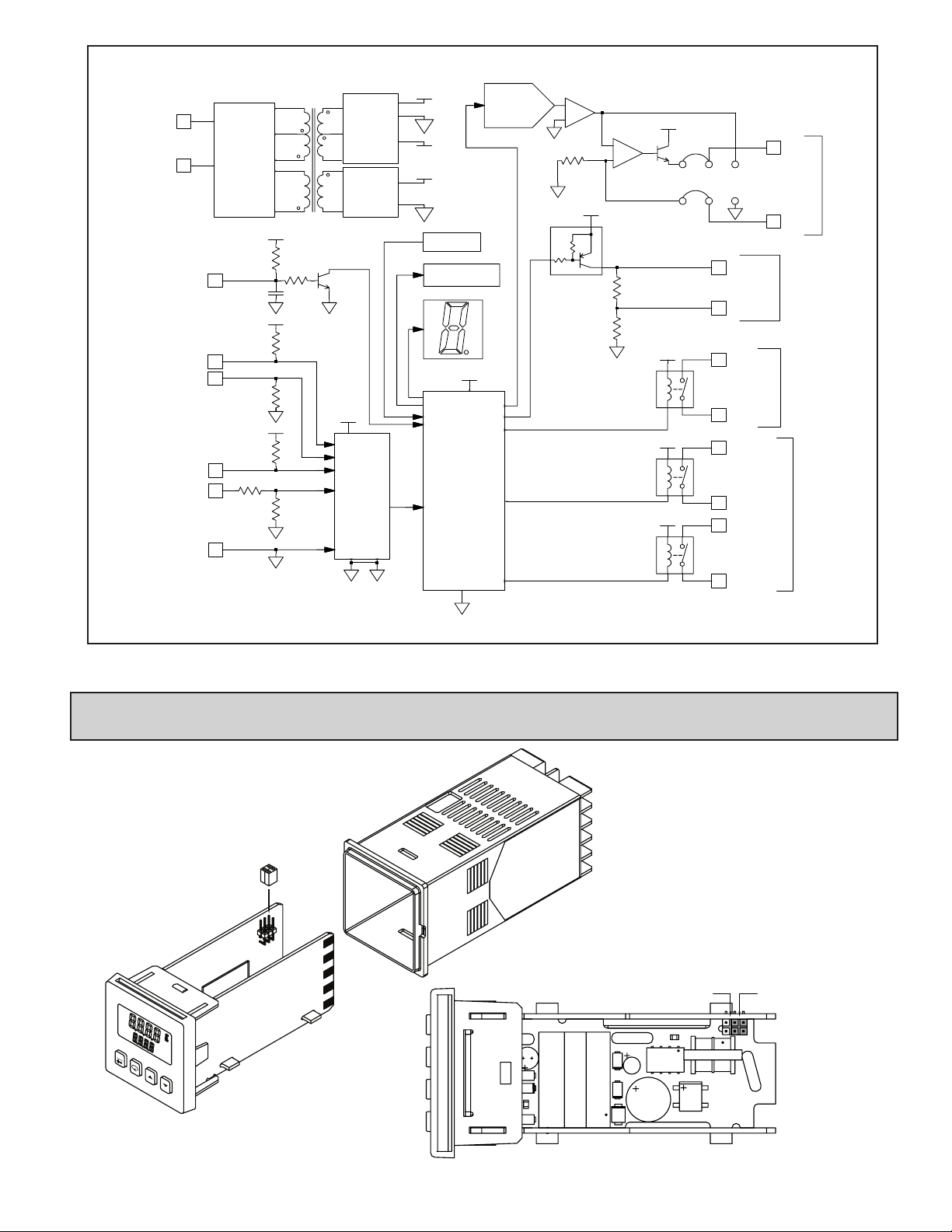
BLOCK DIAGRAM
02
F1
RDY
A2
01
A1
°
%PW
MAN
%
11
POWER
INPUT
12
USER IN
CN63200 RTD EXC
CN63400 0-20 mA
CN63200 TC+
CN63400 0-10V
INPUT COMM
POWER
CONTROL
CIRCUITRY
1
10
10
9
9
8
100K
.01µF
10
20M
976K
+0.7V
Ω
+7V
+5V
D
A
A
A
100K
4.02K
20K
D
POWER
SUPPLY
OPTION
POWER
SUPPLY
+5V
A/D
Converter
+7V
D
-6.2V
+22V
O
Keypad
2
E Memory
Process
Circuitry
DA
+5V
D
D/A
CONV.
+
-
O
25.5
Ω
O
+7V
*A1 becomes main control O1, if selected for heating in the
analog out models.
+
-
D
100K
8.2
+22V
20mA
10V
(REAR)
(FRONT)
O
(+) O1
6
(-) O1
7
Ω
+7V
+7V
+7V
(+) O1
6
(-) O1
7
A1/O1 N.O. *
2
A1/O1 COMM
3
A2/O2 N.O.
4
A2/O2 COMM
5
6
7
+V/+I
-V/-I
MODELS
ANALOG OUTPUT
MODELS
SSR DRIVE
MAIN CONTROL
OUTPUT
ALARM OUTPUT MODELS
1.0 Setting the JumperS (AnAlog output modelS only)
To insure proper operation, the Analog Output jumpers must be set to the
same range selected in programming Module 2-OP. The default jumper
setting is for 20 mA. The default setting in Module 2-OP is 4-20 mA.
To access the jumpers, insert a flat-blade screwdriver between the
front panel and the side case slot. This should disengage the
top and bottom front panel latches from the case
grooves. Pull the front panel assembly with the
controller boards out of the case. The
jumpers are located inside the
controller on the left board along the
back top section.
10V (Both jumpers toward
the front of the unit)
VIEW FROM TOP OF UNIT
20mA (Both jumpers toward
the rear of the unit)
5
Page 6
+-
~~
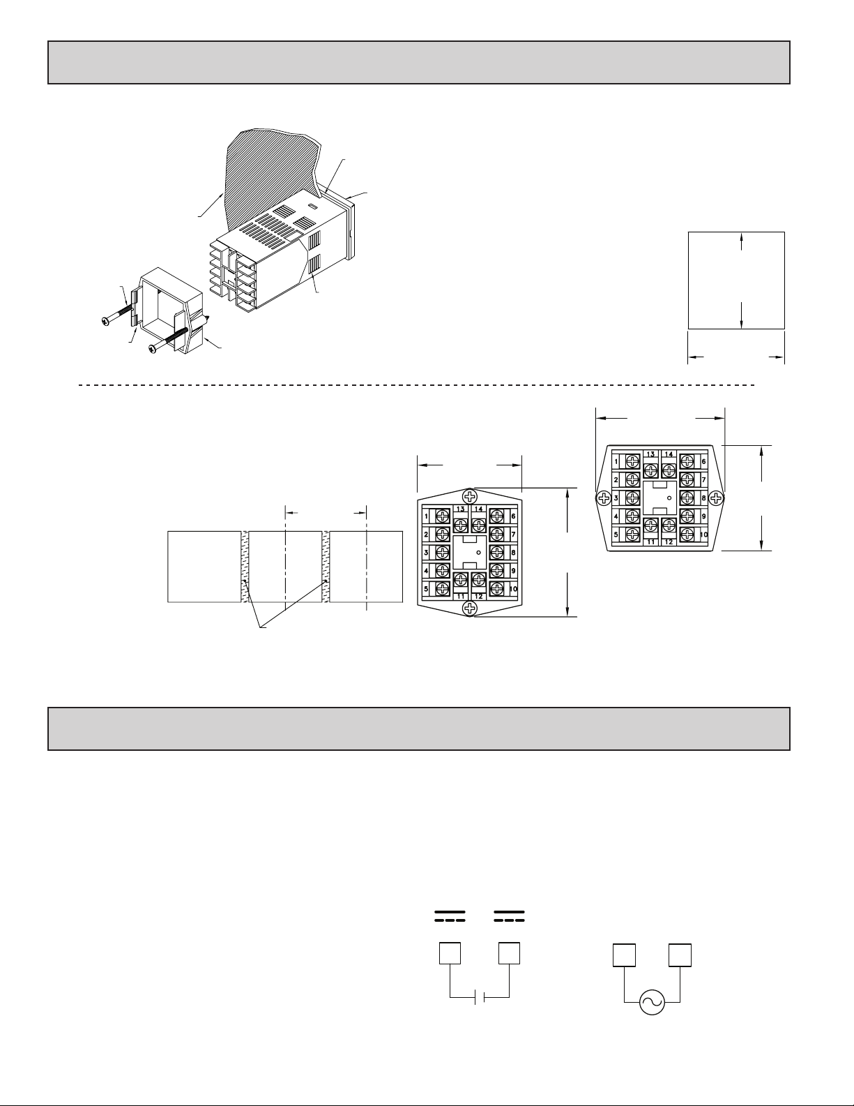
2.0 inStAlling the Controller
1413
6
7
8
10
9
LATCHING
BEZEL
LATCHING
PANEL LATCH
PANEL
MOUNTING
SCREW
TABS
SLOTS
PANEL
PANEL GASKET
1.96 (49.8)
MIN
STANDARD
PANEL
CUT-OUT
IF NEMA 4 IS NOT REQUIRED,
THIS PANEL MATERIAL MAY BE REMOVED.
The CN63200 and CN63400 controllers meet NEMA 4X/IP65 requirements
for indoor use to provide a watertight seal in steel panels with a minimum
thickness of 0.09", or aluminum panels with
a minimum thickness of 0.12". The
controllers are designed to be mounted
into an enclosed panel. The bezel
assembly must be in place during
installation of the controller.
Multiple Controller Stacking
The controller is designed to allow for close spacing of multiple controllers
in applications that do not require protection to NEMA 4X. Controllers can be
stacked either horizontally or vertically. For vertical stacking, install the panel
latch with the screws to the sides of the controller. For horizontal stacking, the
panel latch screws should be at the top and bottom of the controller. The
minimum spacing from centerline to centerline of controllers is 1.96" (49.8
mm). This spacing is the same for vertical or horizontal stacking.
Note: When stacking
controllers, provide
adequate panel
ventilation to ensure
that the maximum
operating temperature
range is not exceeded.
Instructions:
1. Prepare the panel cutout to the proper dimensions.
2. Remove the panel latch from the controller. Discard the cardboard sleeve.
3. Carefully remove the center section of the panel gasket and discard. Slide the
panel gasket over the rear of the controller, seating it against the lip at the
front of the case.
4. Insert the controller into the panel cutout. While holding the controller in
place, push the panel latch over the rear of the controller, engaging the tabs
of the panel latch in the farthest forward slot possible.
5. To achieve a proper seal, tighten the panel latch screws evenly until the
controller is snug in the panel, torquing the screws
to approximately 7 in-lb (79 N-cm). Overtightening
can result in distortion of the controller, and
reduce the effectiveness of the seal.
Note: The installation location of the controller is
important. Be sure to keep it away from heat
sources (ovens, furnaces, etc.) and away from
direct contact with caustic vapors, oils, steam, or
any other process by-products in which exposure
may affect proper operation.
2.39 (60.7)
MAX.
1.96 (49.8)
MAX
2.39 (60.7)
MAX
1.772
(45 )
1.772
(45 )
+0.024
-0.000
+0.6
-0.0
+0.024
-0.000
+0.6
-0.0
1.96 (49.8)
MAX.
3.0 Wiring the Controller
WIRING CONNECTIONS
All wiring connections are made to the rear screw terminals. When wiring the
controller, use the numbers on the label and those embossed on the back of the
case, to identify the position number with the proper function.
All conductors should meet voltage and current ratings for each terminal.
Also, cabling should conform to appropriate standards of good installation, local
CONTROLLER POWER CONNECTIONS
For best results, the power should be relatively “clean” and within
the specified limits. Drawing power from heavily loaded circuits or
from circuits that also power loads that cycle on and off should be
avoided. It is recommended that power supplied to the controller be
protected by a fuse or circuit breaker.
codes and regulations. It is recommended that power (AC or DC) supplied to the
controller be protected by a fuse or circuit breaker. Strip the wire, leaving
approximately 1/4" (6 mm) bare wire exposed (stranded wires should be tinned
with solder). Insert the wire under the clamping washer and tighten the screw
until the wire is clamped tightly.
VDC
DC-DC+
1211
VAC
ACAC
1211
6
Page 7
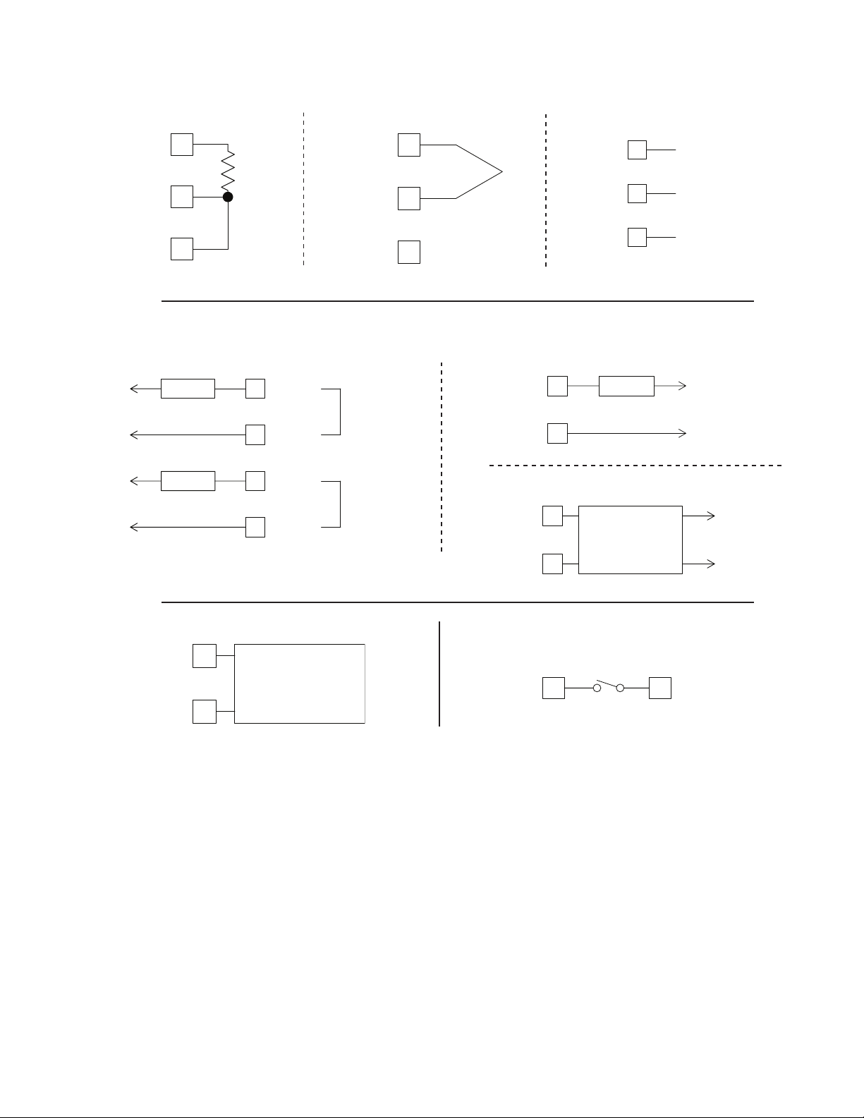
INPUT CONNECTIONS
For two wire RTDs, install a copper sense lead of the same gauge and length
as the RTD leads. Attach one end of the wire at the probe and the other end to
input common terminal. Complete lead wire compensation is obtained. This is
the preferred method. If a sense wire is not used, then use a jumper. A
temperature offset error will exist. The error may be compensated by
programming a temperature offset.
RTD and Resistance Thermocouple and Millivolt
COMM 8
TC+9
RTD 10
COMM 8
TC+
RTD
10
9
CONTROL AND ALARM OUTPUT CONNECTIONS
Alarm Models Main Control Relay Models
2N.O.
3
COMM.
4
N.O.
COMM.
5
A1/O1*
A2/O2
AC/DC
POWER
AC/DC
POWER
LOAD
LOAD
*A1 becomes main control O1, if selected for
heating in the analog out models.
TC-
TC+
(+) O1
(-) O1
(+) O1
(-) O1
Voltage and Current
10V
8
9
10
LOAD
COMM
20mA
6
DC-
DC+ VOLTAGE
DC+ CURRENT
AC/DC
POWER
7
Main Control Logic/SSR Models
+
6
SSR
POWER
UNIT
-
7
AC
AC POWER
AC
ANALOG DC OUTPUT CONNECTIONS
+ V/I
6
CONTROLLER,
RECORDER
- V/I
7
USER INPUT CONNECTIONS
USER
INPUT
81
COMM.
7
Page 8
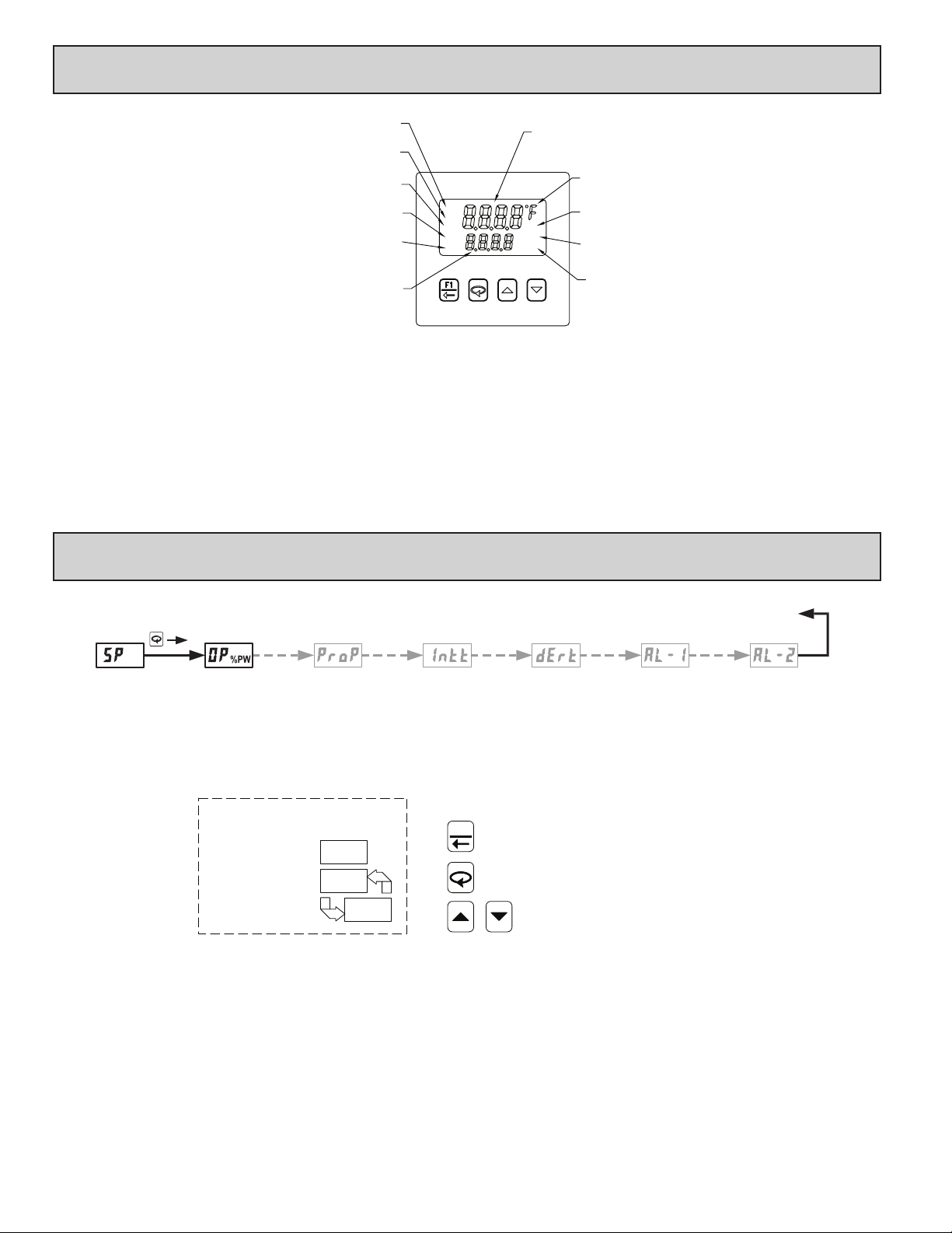
4.0 revieWing the Front KeyS And diSplAy
FLASHES WHEN RAMPING
SETPOINT IS ACTIVE.
ILLUMINATES WHEN ALARM 1
OUTPUT IS ACTIVE.
ILLUMINATES WHEN ALARM 2
CONTROL OUTPUT IS ACTIVE.
(SECONDARY) OUTPUT IS ACTIVE.
DISPLAYS SETPOINT OR % OUTPUT POWER.
ALSO DISPLAYS PARAMETER NAME AND VALUE
IN DISPLAY AND HIDDEN LOOPS OR
PARAMETER VALUE IN CONFIGURATION LOOP.
OUTPUT IS ACTIVE.
ILLUMINATES WHEN MAIN
ILLUMINATES WHEN COOLING
BOTTOM DISPLAY
FRONT PANEL KEYS
L
The F1 key is pressed to exit (or escape) directly to the start of the
Display Loop. While in the Display Loop, the F1 key can be pressed to
activate its programmed function.
The Loop key is pressed to advance to the next parameter, to activate
a changed selection/value, and when held for three seconds, enter the
R
A
A
1
2
21OO
J
TOP DISPLAY
DISPLAYS TEMPERATURE/PROCESS VALUE.
ALSO DISPLAYS PARAMETER NAME IN
CONFIGURATION LOOP.
ILLUMINATES WHEN °F or °C
IS SELECTED. (CN63200 ONLY)
ILLUMINATES WHEN PERCENT
IS SELECTED. (CN63400 ONLY)
ILLUMINATES WHEN CONTROLLER
IS IN MANUAL MODE.
ILLUMINATES WHEN OUTPUT POWER
PERCENTAGE IS SHOWN.
MAN
%WP
%
The Arrow keys are used to scroll through parameter selections/
values and in the Configuration Loop they are used to scroll to the
appropriate Parameter Module.
Hidden Loop.
5.0 progrAmming: diSplAy loop
DISPLAY LOOP
SETPOINT
VALUE
Note: Setpoint and Output Power are the only parameters visible in the Display Loop with Factory Settings. The remaining parameters can
be selected for the Display Loop within Module 3.
Parameter availability is model and programming dependent.
OUTPUT
POWER
PROPORTIONAL
BAND
INTEGRAL
TIME
FRONT DISPLAY
TOP DISPLAY
TEMP/PROCESS
BOTTOM DISPLAY
PARAMETER
SELECTION/VALUE
DISPLAY LOOP
At power up, all display segments light, and then the programmed input type
and the controller’s software version will flash. Then the Temperature/Process
Value is shown in the top display , and the Setpoint Value is shown in the bottom
display. This is the Display Loop. If the Setpoint is hidden or locked, the Display
Loop will default to Output Power. If Output Power is also hidden or locked out,
the bottom display is blank. During programming, the F1 key can be pressed to
return the controller to this point. (Only in the Display Loop will the F1 key
perform the user
function programmed in Input Module .)
DERIVATIVE
TIME
F1
ENDS AND RETURNS TO START OF DISPLAY LOOP.
ADVANCES TO NEXT PARAMETER.
CHANGES SELECTION/VALUE.
ALARM1
VALUE
ALARM2
VALUE
When the is pressed the controller advances to the next parameter in the
Display Loop. Except for Setpoint and % Output Power, the bottom display
alternates between the parameter name and its selection/value. The arrow keys
are pressed to change the selection/value for the shown parameter. The new
selection/value is activated when the is pressed. Display Loop parameters
may be locked out or hidden in Lockout Module
. Some parameters are
model and programming dependent.
8
Page 9

The values shown for the displays are the factory settings.
SETPOINT VALUE (SP1) *
CN63200
CN63400
CN63200
CN63400
Typically, the controller is operating with the Setpoint value in the bottom
display. There is no annunciator nor parameter indication for Setpoint in the
Display Loop. The parameter name alternates with the setpoint value in the
Hidden Loop. The Setpoint value can be changed, activated and stored by
pressing the arrow keys. This is the only parameter that can be configured as
read only in the Display Loop, but read/write in the Hidden Loop. It is possible
to store a second Setpoint value that can be selected in the Hidden Loop, by the
F1 key or the user input. Both Setpoint values are limited by the Setpoint Low
and High Limits in Input Module
to
SETPOINT VALUE (SP2) *
to
.
% OUTPUT POWER *
to
The % Output Power is shown with the %PW annunciator. The parameter
name alternates with the % Output Power value in the Hidden Loop. While the
controller is in Automatic Mode, this value is read only. When the controller is
placed in Manual Mode, the value can be changed, activated and stored by
pressing the arrow keys. For more details on % Output Power, see Control
Mode Explanations.
OUTPUT POWER OFFSET
When the Integral Time is set to zero and the controller is in the Automatic
Mode, this parameter will appear after % Output Power. It is also shown with
the %PW annunciator illuminated. The power offset is used to shift the
proportional band to compensate for errors in the steady state. If Integral Action
is later invoked, the controller will re-calculate the internal integral value to
provide “bumpless” transfer and Output Power Offset will not be necessary.
to
INTEGRAL TIME
Integral action shifts the center point position of the proportional band to
eliminate error in the steady state. The higher the integral time, the slower the
response. The optimal integral time is best determined during PID Tuning. If
time is set to zero, the previous Integral output power value is maintained.
Offset Power can be used to provide Manual Reset.
Derivative time helps to stabilize the response, but too high of a derivative
time, coupled with noisy signal processes, may cause the output to fluctuate too
greatly, yielding poor control. Setting the time to zero disables derivative action.
On models with alarms, the value for Alarm 1 can be entered here. The value
is either absolute (absolute alarm types) or relative to the Setpoint value
(deviation and band alarm types.) When Alarm 1 is programmed for or
, this parameter is not available. For more details on alarms, see Alarm
Module .
On models with alarms, the value for Alarm 2 can be entered here. The value
is either absolute (absolute alarm types) or relative to the Setpoint value
(deviation and band alarm types.) When Alarm 2 is programmed for or
, this parameter is not available. For more details on alarms, see the Alarm
Module .
to seconds
DERIVATIVE TIME
to seconds per repeat
ALARM 1 VALUE
to
CN63200
CN63400
ALARM 2 VALUE
to
CN63200
CN63400
PROPORTIONAL BAND
The proportional band should be set to obtain the best response to a process
disturbance while minimizing overshoot. A proportional band of 0.0% forces
the controller into On/Off Control with its characteristic cycling at Setpoint. For
more information, see Control Mode and PID Tuning Explanations.
to
(% of full input range)
* Alternating indication only used in the Hidden Loop.
9
Page 10
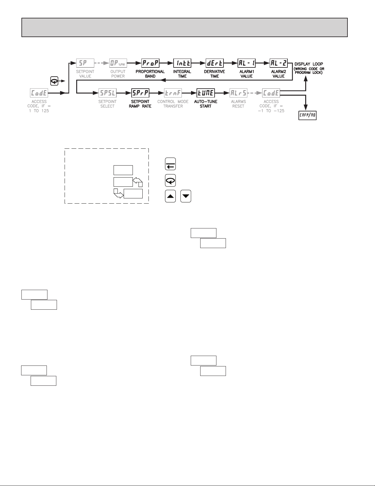
6.0 progrAmming: hidden loop
To enter Hidden Loop, press for 3 seconds.
Note: Parameters shown bold are the only parameters visible in the Hidden Loop with Factory Settings. Setpoint and Output Power are
factory set for the Display Loop. The remaining parameters can be selected for the Hidden Loop within Module 3.
Parameter availability is model and programming dependent.
FRONT DISPLAY
TOP DISPLAY
TEMP/PROCESS
BOTTOM DISPLAY
PARAMETER
SELECTION/VALUE
HIDDEN LOOP
F1
ENDS AND RETURNS TO START OF DISPLAY LOOP.
ADVANCES TO NEXT PARAMETER.
CHANGES SELECTION/VALUE.
HIDDEN LOOP
When is pressed and held for three seconds, the controller advances to the
Hidden Loop. The Temperature/Process Value is shown in the top display. The
bottom display alternates between the parameter and its selection/value. or
J is pressed to change the selection/value for the shown parameter. The new
selection/value is activated after is pressed. When
controller returns to the Display Loop and stores changed selection/values to
permanent memory. Hidden Loop parameters may be locked out in Lockout
Module . Some parameters are model and programming dependent.
ACCESS CODE
If the Access Code is set from 1 to 125, in Lockout Module , Access
Code will appear here. By entering the proper Code, access to the Hidden Loop
is permitted. With the factory setting of 0, Access Code will not appear in the
Hidden Loop. A universal code of 111 can be entered to gain access,
independent of the programmed code number.
to
L is pressed, the
The setpoint ramp rate can reduce sudden shock to the process and reduce
overshoot on startup or after setpoint changes, by ramping the setpoint at a
controlled rate. R annunciator flashes while ramping. With the CN63200, the
ramp rate is always in tenths of degrees per minute, regardless of the resolution
chosen for the process display. With the CN63400, the ramp rate is in leastsignificant (display units) digits per minute. A value of 0.0 or 0 disables setpoint
ramping. Once the ramping setpoint reaches the target setpoint, the setpoint ramp
rate disengages until the setpoint is changed again. If the ramp value is changed
during ramping, the new ramp rate takes effect. If the setpoint is ramping prior to
starting Auto-Tune, the ramping is suspended during Auto-Tune and then
resumed afterward. Deviation and band alarms are relative to the target setpoint,
not the ramping setpoint. A slow process may not track the programmed setpoint
rate. At power up, the ramping setpoint is initialized at the ambient temperature/
process value.
SETPOINT RAMP RATE
to
SETPOINT SELECT
The SPSL function allows the operator to switch from or to, setpoint 1 and
setpoint 2. In the Display Loop, there is no annunciator indicating the selected
Setpoint, however, the selected Setpoint value is displayed and activated.
or
CONTROL MODE TRANSFER
In Automatic Mode, the percentage of Output Power is automatically
determined by the controller. In Manual/User Mode, the percentage of
Output Power is adjusted manually while in the Display Loop. The Control
Mode can also be transferred through the F1 Key or User Input. For more
information, see Control Mode Explanations.
10
Page 11
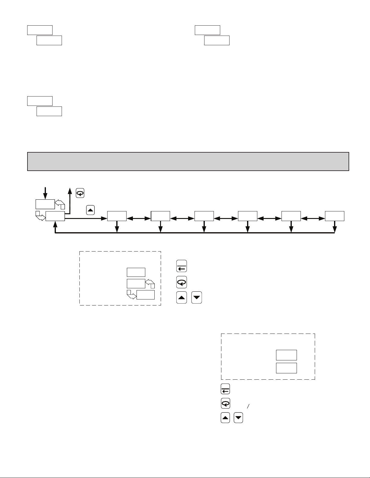
AUTO-TUNE START
ACCESS CODE
The Auto-Tune procedure of the controller sets the Proportional Band,
Integral Time, Derivative Time, Digital Filter, Control Output Dampening
Time, and Relative Gain (Heat/Cool) values appropriate to the characteristics of
the process. This parameter allows front panel starting or stopping of
Auto-Tune. For more information, see PID Tuning Explanations.
With alarm models, the alarms can be manually reset. The up key resets
Alarm 1 and the down key resets Alarm 2.
ALARMS RESET
If the Access Code is set from -1 to -125, in Lockout Module , Access
Code will appear here. By entering the proper Code, access to the Configuration
Loop is permitted (with a negative Code value, the Hidden Loop can be
accessed without the use of a code). With the factory setting of 0 or with an
active User Input configured for Program Lock (), Access Code will not
appear here. An active user input configured for Program Lock () always
locks out the Configuration Loop, regardless of Access Code.
to
7.0 progrAmming: ConFigurAtion loop
HIDDEN DISPLAY
LOOP
LOOP
INPUT
PARAMETERS
MODULE MODULE
CONFIGURATION LOOP
OUTPUT
PARAMETERS
LOCKOUT
PARAMETERS
MODULE
ALARM
PARAMETERS
MODULE
COOLING
PARAMETERS
MODULE
FACTORY
SERVICE
MODULE
FRONT DISPLAY
TOP DISPLAY
TEMP/PROCESS
BOTTOM DISPLAY
CNFP/MODULE
F1
To access the Configuration Loop, press the up key when / is displayed
in the Hidden Loop. The arrow keys are used to select the parameter module
(1-9). To enter a specific module press while the module number is
displayed. In the Configuration Loop, will alternate with the parameter
number in the bottom display. The Temperature/Process Value is shown in the
top display.
After entering a parameter module, press to advance through the
parameter names in the module. To change a parameter’s selection/value, press
the arrow keys while the parameter is displayed. In the modules, the top display
shows the parameter name, and the bottom display shows the selection/value.
Use to enter any selection/values that have been changed. The change is not
committed to permanent memory until the controller is returned to the Display
Loop. If a power loss occurs before returning to the Display Loop, the new
values must be entered again.
At the end of each module, the controller returns to /. At this location,
pressing again returns the display to the the Display Loop. Pressing the Up
key allows re-entrance to the Configuration Loop. Whenever
momentarily appears as the parameters are stored to permanent memory and the
controller returns to the Display Loop.
L is pressed,
ENDS AND RETURNS TO START OF DISPLAY LOOP.
ENTERS MODULE OR AT
RETURNS TO DISPLAY LOOP.
ADVANCES TO NEXT MODULE.
CNFP/NO
FRONT DISPLAY
TOP DISPLAY
PARAMETER
BOTTOM DISPLAY
SELECTION/VALUE
F1
ENDS AND RETURNS TO START
OF DISPLAY LOOP.
ADVANCES TO NEXT PARAMETER OR
AT RETURNS TO DISPLAY LOOP.
ADVANCES SELECTION/VALUE.
11
Page 12
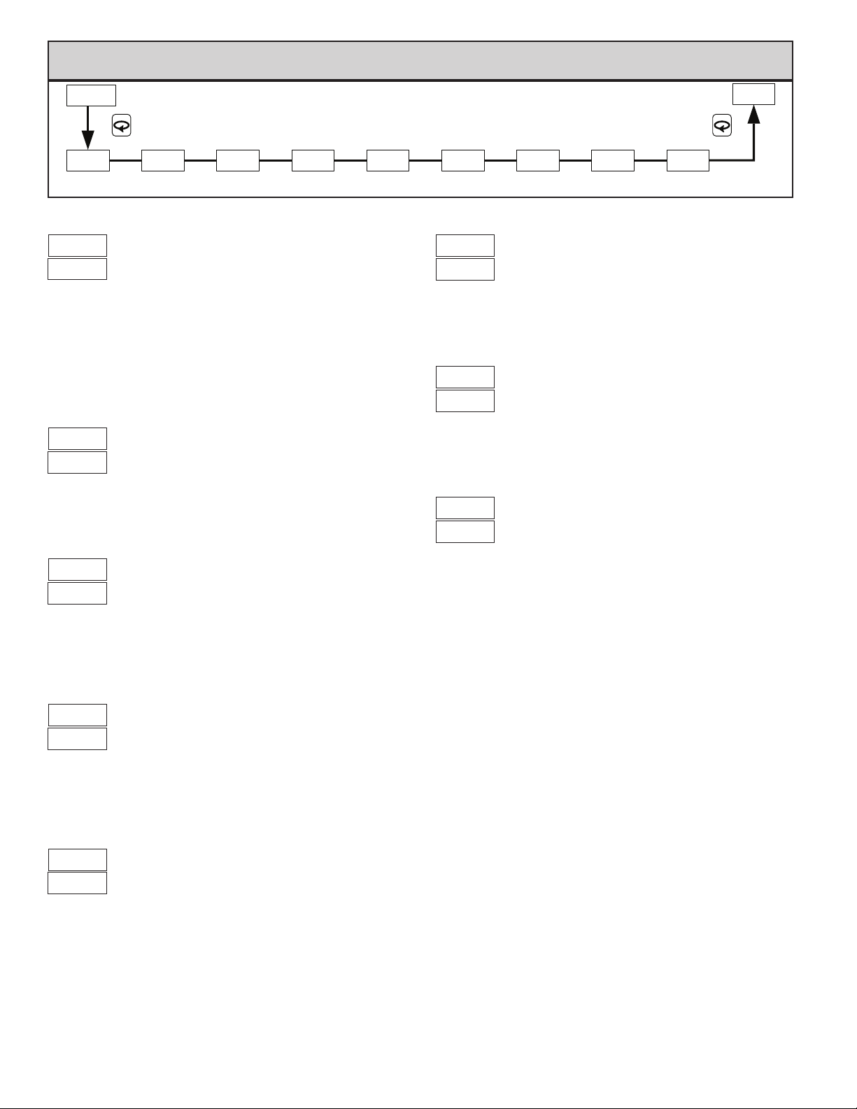
7.1 module 1 - input pArAmeterS () Cn63200 only
TYPE
SCALE
RESOLUTION
FILTERING OFFSET
HIGH LIMIT
LOW LIMIT
INPUT
FUNCTION
INPUT
Select the input type that corresponds to the input sensor.
Select either degrees Fahrenheit or Celsius. For linear mV and ohms input
types, this has no effect. If changed, adjust related parameter values, as the
controller does not automatically convert them.
Select whole degrees, or tenths of degrees for Temperature display, Setpoint
values, and related parameters. For Linear Resistance inputs , the same
parameter selections apply in ohms or tenths of an ohm. For mV inputs ,
only hundredths of a mV resolution is available.
TEMP
SELECTION TYPE SELECTION TYPE
T TC
E TC
J TC
K TC
R TC
S TC
B TC
TEMPERATURE SCALE
DECIMAL
INPUT TYPE
N TC
C TC
Linear mV
RTD 385
RTD 392
RTD 672
Linear Ohms
Fahrenheit
Celsius
DECIMAL RESOLUTION
to for temperature and resistance inputs
for mV inputs
DIGITAL FILTERING
= least to = most
PARAMETER MENU
DIGITAL
SHIFT/
The filter is an adaptive digital filter that discriminates between measurement
noise and actual process changes. If the signal is varying too greatly due to
measurement noise, increase the filter value. If the fastest controller response is
needed, decrease the filter value.
SHIFT/OFFSET
to degrees
This value offsets the controller’s temperature display value by the entered
amount. This is useful in applications in which the sensor cannot provide the
actual temperature signal due to mounting constraints, inaccuracy, etc.
F1 KEY
SETPOINTSETPOINT
SETPOINT LOW LIMIT
to
USER
The controller has a programmable low setpoint limit value to restrict the
setting range of the setpoint. Set the limit so that the setpoint value cannot be
set below the safe operating area of the process.
SETPOINT HIGH LIMIT
to
The controller has a programmable high setpoint limit value to restrict the
setting range of the setpoint. Set the limit so that the setpoint value cannot be
set above the safe operating area of the process.
USER INPUT FUNCTION (OPTIONAL)
SELECTION FUNCTION SELECTION FUNCTION
No Function
Program Lock
Integral Action Lock
Auto/Manual Select
The controller performs the selected User Input function (User Input
available only on models with alarms), when the User terminal 1 is connected
(pulled low) to Common terminal 8.
No Function: No function is performed.
Program Lock: The Configuration Loop is locked, as long as activated
(maintained action).
Integral Action Lock: The integral action of the PID computation is disabled
(frozen), as long as activated (maintained action).
Auto/Manual Select: This function selects (maintained action) Automatic
(open) or Manual Control (activated).
Setpoint 1 or 2 Select: This function selects (maintained action) Setpoint
1(open) or Setpoint 2 (activated) as the active setpoint.
Setpoint Ramp Disable: The setpoint ramping feature is disabled, as long as
activated (maintained action). Any time the user input is activated with a
ramp in process, ramping is aborted.
Reset Alarms: Active alarms are reset, as long as activated (maintained action).
Active alarms are reset until the alarm condition is cleared and triggered
again (momentary action).
Setpoint 1 or 2 Select
Setpoint Ramp Disable
Reset Both Alarms
12
Page 13
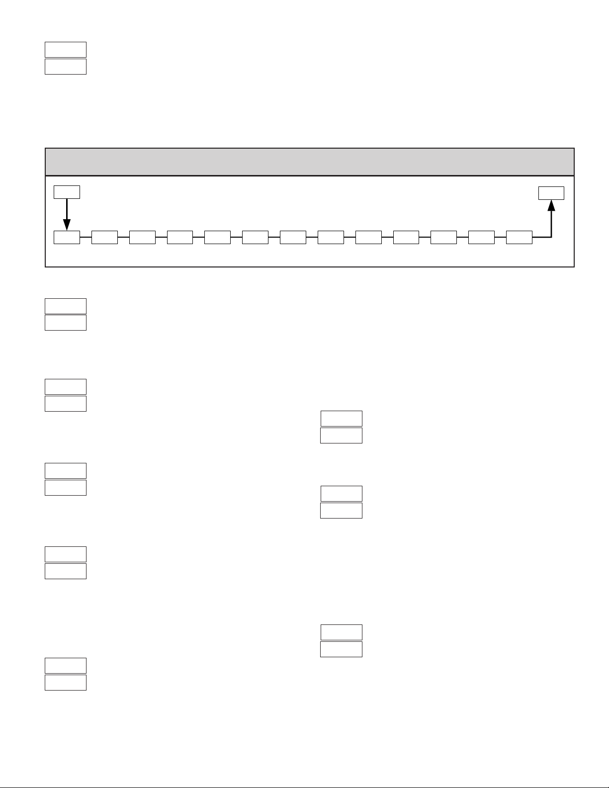
No Function
Auto/Manual Select
Setpoint 1 or 2 Select
F1 KEY FUNCTION
Reset Alarm 1
Reset Alarm 2
Reset Both Alarms
FUNCTIONSELECTIONFUNCTIONSELECTION
The controller performs the selected F1 Key Function, when L is pressed
while in the Display Loop. In any other loop or module location, pressing
will perform an escape to the Display Loop.
No Function: No function is performed.
Auto/Manual Select: This function toggles (momentary action) the controller
between Automatic and Manual Control.
Setpoint 1 or 2 Select: This function toggles (momentary action) the controller
between Setpoint 1 and Setpoint 2.
Reset Alarms: This function can be used to reset one or both of the alarms
when activated (momentary action) The alarm will remain reset until the
alarm condition is cleared and triggered again.
7.1 module 1 - input pArAmeterS () Cn63400 only
L
PARAMETER MENU
A
INPUT
TYPE
PERCENT
SYMBOL
DECIMAL
RESOLUTION
Select the input type that corresponds to the input signal.
This only illuminates the % annunciator. It does not perform any type of
percent function, but is useful in applications that have been scaled in percent.
PERCENT ANNUNCIAT OR
On
Off
DECIMAL RESOLUTION
ROUNDING
INCREMENT
INPUT TYPE
TYPESELECTION
Current
Voltage
DIGITAL
FILTERING
DISPLAY
VALUE 1
INPUT
VALUE 1
This selection affects the decimal point placement for the Process value, and
related parameters.
ROUNDING INCREMENT
Rounding selections other than 1 cause the process value display to round to
the nearest rounding increment selected. (For example, rounding of 5 causes 122
to round to 120 and 123 to round to 125.) Rounding starts at the least significant
digit of the process value. Setpoint values, Setpoint limits, Alarm values, Input
Scaling values, and Analog Scaling values are not affected by rounding.
to
In steps of 1 least significant digit,
regardless of decimal point.
DIGITAL FILTERING
= least to = most
The filter is an adaptive digital filter that discriminates between measurement
noise and actual process changes. If the signal is varying too greatly due to
measurement noise, increase the filter value. If the fastest controller response is
needed, decrease the filter value.
A
DISPLAY
VALUE 2
SCALING
To scale the controller , two scaling points are necessary. Each scaling point has
a coordinate pair of Display Values and Input Values. It is recommended that the
two scaling points be at the low and high ends of the input signal being measured.
Process value scaling will be linear between and continue past the entered points
to the limits of the input range. (Factory settings example will display 0.0 at 4.00
mA input and display 100.0 at 20.00 mA input.) Reverse acting indication can be
accomplished by reversing the two signal points or the Display value points, but
not both. If both are reversed, forward (normal) acting indication will occur. In
either case, do not reverse the input wires to change the action.
INPUT
VALUE 2
SETPOINT
LOW LIMIT
DISPLAY VALUE SCALING POINT 1
to
SETPOINT
HIGH LIMIT
USER
INPUT
F1 KEY
FUNCTION
Enter the first coordinate Display Value by using the arrow keys.
INPUT VALUE SCALING POINT 1
For Key-in Method, enter the first coordinate Input Value by using the arrow
keys. To allow the CN63400 to “learn” the signal, use the Applied Method. For
Applied Method, press
applied method. Adjust the applied signal level externally until the appropriate
value appears under . Using either method, press to store the value for
. (The controller can be toggled back to the Key-in Method by pressing
before .)
to mA
to V
L. The ° annunciator is turned on to indicate the
DISPLAY VALUE SCALING POINT 2
to
Enter the second coordinate Display Value by using the arrow keys.
L
13
Page 14

INPUT VALUE SCALING POINT 2
F1 KEY FUNCTION
For Key-in Method, enter the second coordinate Input Value by using the
arrow keys. To allow the CN63400 to “learn” the signal, use the Applied
Method. For Applied Method, press
indicate the applied method. Adjust the applied signal level externally until the
appropriate value appears under . Using either method, press to store
the value for . (The controller can be toggled back to the Key-in Method by
pressing
to mA
to V
L. The ° annunciator is turned on to
L before .)
SETPOINT LOW LIMIT
to
The controller has a programmable low setpoint limit value to restrict the
setting range of the setpoint. Set the limit so that the setpoint value cannot be
set below the safe operating area of the process.
SETPOINT HIGH LIMIT
to
The controller has a programmable high setpoint limit value to restrict the
setting range of the setpoint. Set the limit so that the setpoint value cannot be
set above the safe operating area of the process.
FUNCTIONSELECTIONFUNCTIONSELECTION
No Function
Auto/Manual Select
Setpoint 1 or 2 Select
The controller performs the selected F1 key function, when L is pressed
while in the Display Loop. In any other loop or module location, pressing
will perform an escape to the Display Loop.
No Function: No function is performed.
Auto/Manual Select: This function toggles (momentary action) the controller
between Automatic and Manual Control.
Setpoint 1 or 2 Selection: This function toggles (momentary action) the
controller between Setpoint 1 and Setpoint 2.
Reset Alarms: This function can be used to reset one or both of the alarms
when activated (momentary action). The alarm will remain reset until the
alarm condition is cleared and triggered again.
Reset Alarm 1
Reset Alarm 2
Reset Both Alarms
L
USER INPUT FUNCTION (OPTIONAL)
SELECTION FUNCTION SELECTION FUNCTION
No Function
Program Lock
Integral Action Lock
Auto/Manual Select
The controller performs the selected User Input function (User Input
available only on models with alarms), when the User terminal 1 is connected
(pulled low) to Common terminal 8.
No Function: No function is performed.
Program Lock: The Configuration Loop is locked, as long as activated
(maintained action).
Integral Action Lock: The integral action of the PID computation is disabled
(frozen), as long as activated (maintained action).
Auto/Manual Select: This function selects (maintained action) Automatic
(open) or Manual Control (activated).
Setpoint 1 or 2 Select: This function selects (maintained action) Setpoint
1(open) or Setpoint 2 (activated) as the active setpoint.
Setpoint Ramp Disable: The setpoint ramping feature is disabled, as long as
activated (maintained action). Any time the user input is activated with a
ramp in process, ramping is aborted.
Reset Alarms: Active alarms are reset, as long as activated (maintained action).
Active alarms are reset until the alarm condition is cleared and triggered
again (momentary action).
Setpoint 1 or 2 Select
Setpoint Ramp Disable
Reset Both Alarms
14
Page 15
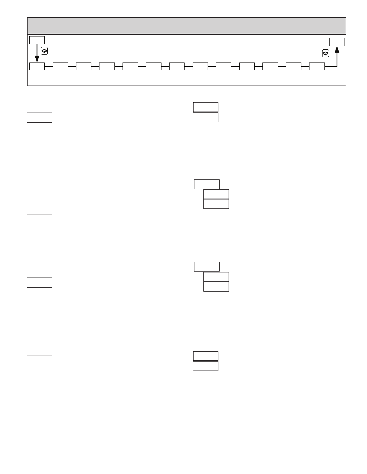
7.2 module 2 - output pArAmeterS ()
2-OP
PARAMETER MENU
CYCt OPLOOPAC OPHI OPFL OPdP CHYS
CYCLE
TIME
CONTROL
ACTION
OUTPUT
POWER CONTROL
LOW LIMIT HIGH LIMIT
OUTPUT
POWER
CYCLE TIME
POWER CODE
LEVEL DAMPENING HYSTERESISRANGE ASSIGNMENT TIME SCALING SCALING
OUTPUT
POWER
to seconds
ON/OFF
The Cycle Time is entered in seconds with one tenth of a second resolution.
It is the total time for one on and one off period of the time proportioning
control output O1. With time proportional control, the percentage of power is
converted into an output on-time relative to the cycle time value set. (If the
controller calculates that 65% power is required and a cycle time of 10.0
seconds is set, the output will be on for 6.5 seconds and off for 3.5 seconds.)
For best control, a cycle time equal to one-tenth or less, of the natural period of
oscillation of the process is recommended. When using the Analog Output
signal for control, the Cycle Time setting has no effect. If the O1 output is not
being used, a cycle time of 0 can be entered to prevent the output and indicator
from cycling.
CONTROL ACTION
This determines the control action for the PID loop. Programmed for direct
action (cooling), the output power will increase if the Process value is above the
Setpoint value. Programmed for reverse action (heating), the output power
decreases when the Process Value is above the Setpoint Value. For heat and cool
applications, this is typically set to reverse. This allows O1 or A1 (models with
Analog Output) to be used for heating, and A2/O2 to be used for cooling.
Direct (cooling)
Reverse (heating)
CNFP
tcod ANtP
AUTO-TUNE
ANALOG
OUTPUT
This parameter sets the power level for the control outputs in the event of a
sensor failure. If Alarm 2 is not selected for cooling, the range is from 0% (O1
output full off) to 100% (O1 output full on). If A2 is selected for cooling, the
range is from -100 to +100%. At 0%, both O1 and O2 are off; at 100%, O1 is
on; and at -100%, O2 is on. The alarm outputs are upscale drive with an open
sensor, and downscale drive with a shorted sensor (RTD only), independent of
this setting. Manual Control overrides the sensor fail preset.
ANAS
ANALOG
OUTPUT
SENSOR FAIL POWER LEVEL
to percent O1
to percent O1/O2
OUTPUT POWER DAMPENING
CN63200
CN63400
The Dampening Time, entered as a time constant in seconds, dampens
(filters) the calculated output power. Increasing the value increases the
dampening effect. Generally, dampening times in the range of one-twentieth to
one-fiftieth of the controller’s integral time (or process time constant) are
effective. Dampening times longer than these may cause controller instability
due to the added lag effect.
ON/OFF CONTROL HYSTERESIS
ANUt
ANALOG ANALOG
UPDATE
ANLO
ANALOGSENSOR FAIL
LOW
to seconds
ANHI
HIGH
OUTPUT POWER LOWER LIMIT
This parameter may be used to limit controller power at the lower end due to
process disturbances or setpoint changes. Enter the safe output power limits for
the process. If Alarm 2 is selected for cooling, the range is from -100 to +100%.
At 0%, both O1 and O2 are off; at 100%, O1 is on; and at -100%, O2 is on.
When the controller is in Manual Control Mode, this limit does not apply.
This parameter may be used to limit controller power at the upper end due to
process disturbances or setpoint changes. Enter the safe output power limits for
the process. If Alarm 2 is selected for cooling, the range is from -100 to +100%.
At 0%, both O1 and O2 are off; at 100%, O1 is on; and at -100%, O2 is on.
When the controller is in Manual Control Mode, this limit does not apply.
to percent O1
to percent O1/O2
OUTPUT POWER UPPER LIMIT
to percent O1
to percent O1/O2
CN63200
CN63400
The controller can be placed in the On/Off Control Mode by setting the
Proportional Band to 0.0%. The On/Off Control Hysteresis (balanced around
the setpoint) eliminates output chatter. In heat/cool applications, the control
hysteresis value affects both Output O1 and Output O2 control. It is suggested
to set the hysteresis band to Factory Setting prior to starting Auto-Tune. After
Auto-Tune, the hysteresis band has no effect on PID Control. On/Off Control
Hysteresis is illustrated in the On/Off Control Mode section.
fastest to slowest
to
AUTO-TUNE CODE
Prior to starting Auto-Tune, this code should be set to achieve the necessary
dampening level under PID Control. This value allows customization of the PID
values that Auto-T une will calculate. For the process to be controlled aggressively
(fastest process response with possible overshoot), set the Auto-Tune Code to 0.
For the process to be controlled conservatively (slowest response with the least
amount of overshoot), set this value to 2. If the Auto-Tune Code is changed,
Auto-Tune needs to be reinitiated for the changes to affect the PID settings. For
more information, see PID Tuning Explanations Section.
15
Page 16
ANALOG OUTPUT RANGE (OPTIONAL)
ANALOG LOW SCALING (OPTIONAL)
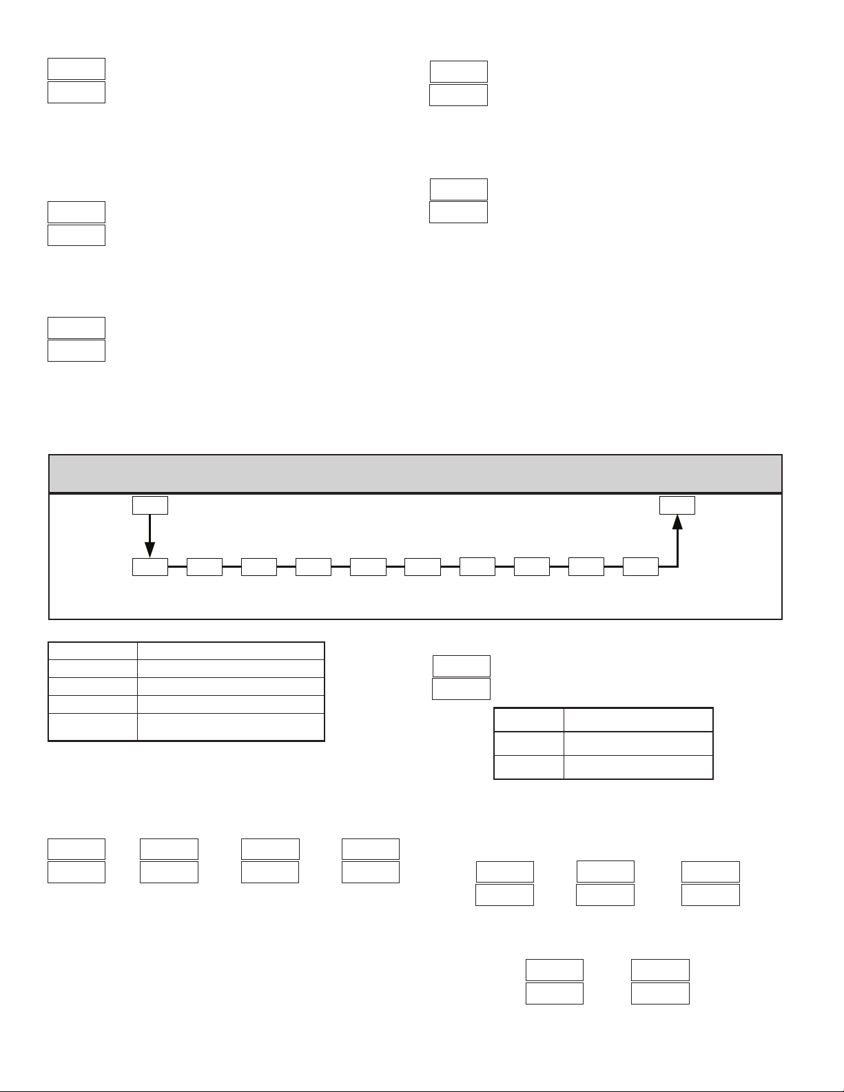
Select the type of output and range. The Analog output jumpers are factory
set to current. They must be changed if voltage output is desired. The Analog
output can be calibrated to provide up to approximately 5% over range
operation (0 mA current can only go slightly negative).
This setting selects the parameter that the Analog Output will retransmit or
track.
The update time of the Analog Output can be used to reduce excess valve
actuator or pen recorder activity.
V mA
mA
ANALOG OUTPUT ASSIGNMENT (OPTIONAL)
Main Control % Output Power
Input Signal Retransmission
Active Setpoint
ANALOG UPDATE TIME (OPTIONAL)
to seconds
= update rate of 0.1 second
to
The Analog Output assignment value that corresponds to 0 V, 0 mA or 4 mA
output as selected.
ANALOG HIGH SCALING (OPTIONAL)
to
The Analog Output assignment value that corresponds to 10 V or 20 mA
output as selected. An inverse acting output can be achieved by reversing the
low and high scaling points.
7.3 module 3 - loCKout pArAmeterS ()
SETPOINT
ACCESS
SELECTION DESCRIPTION
(SP only)
The following parameters can be configured for , , and .
SETPOINT
ACCESS
Display: accessible in Display Loop.
Hide: accessible in Hidden Loop.
Locked: not accessible in either loop.
Display/read: read only in Display Loop,
but read/write in Hidden Loop.
OUTPUT
POWER
ACCESS
OUTPUT
POWER
PID
VALUES
ACCESS ACCESS
PID VALUES
ACCESS
ALARM
VALUES
PARAMETER MENU
ACCESS
CODE
ALARM
VALUES
ACCESS
SETPOINT
SELECT
ACCESSACCESS
SETPOINT
RAMP
ACCESS
CONTROL
TRANSFER
ACCESS
to
to
to
The following parameters can be configured for or only.
SETPOINT
SELECT
ACCESS
RAMP
RESET
ALARMS
ACCESS
CONTROL
TRANSFER
ACCESS
AUTO-TUNE
START
ACCESS
ACCESS CODE
Full access to Display, Hidden,
and Configuration Loops
Code necessary to access
Configuration Loop only.
Code necessary to access
Hidden and Configuration Loops.
SETPOINT
ACCESS
AUTO-TUNE
START
ACCESS
16
RESET
ALARMS
ACCESS
Page 17
7.4 module 4 - AlArm pArAmeterS () (optionAl)
4-AL
ACt1 rSt1
ALARM 1
ACTION
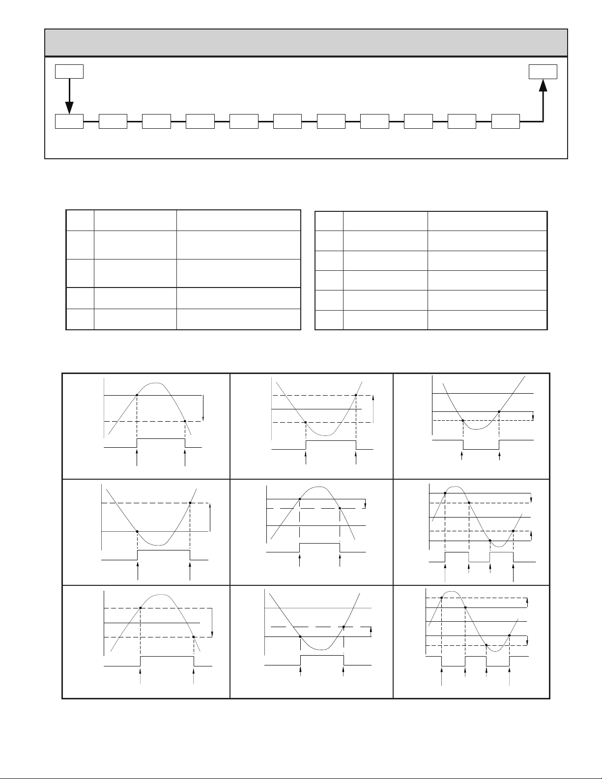
A VAILABLE ALARM ACTIONS
Lit1
ALARM 1
ANNUNCIATOR
None
Absolute High
(balanced hysteresis)
Absolute Low
(balanced hysteresis)
Absolute High
(unbalanced hysteresis)
Absolute Low
(unbalanced hysteresis)
ALARM 1
RESET ANNUNCIATOR
MODE
PARAMETER MENU
Stb1
ALARM 1
STANDBY
No action, the remaining Alarm
parameters are not available.
The alarm energizes when the Process
Value exceeds the alarm value + 1/2
the hysteresis value.
The alarm energizes when the Process
Value falls below the alarm value -1/2
the hysteresis value.
The alarm energizes when the Process
Value exceeds the alarm value.
The alarm energizes when the Process
Value falls below the alarm value.
AL-1
VALUE RESET
ACt2 Lit2
ACTION
ALARM 2ALARM 2
rSt2 stb2
ALARM 2
MODE
Deviation High
Deviation Low
Band Acting
(inside)
Band Acting
(outside)
Heat (A1 Analog
models only)
Cool
(A2 only)
AL-2
ALARM 2
STANDBY
ALARM 2
VALUE
Alarm 1 and 2 value tracks the
Setpoint value
Alarm 1 and 2 value tracks the
Setpoint value
Alarm 1 and 2 value tracks the
Setpoint value
Alarm 1 and 2 value tracks the
Setpoint value
If heating is selected, the remaining
Alarm 1 parameters are not available.
If cooling is selected, the remaining
Alarm 2 parameters are not available.
AHYS
ALARM 1 & 2ALARM 1
HYSTERESIS
CNFP
ALARM ACTION FIGURES
AL
AL - Hys
ALARM
STATE
AL + Hys
ALARM
STATE
AL + ½Hys
AL - ½Hys
OFF ON
TRIGGER POINTS
Absolute High Acting (Unbalanced Hys)
AL
OFF ON
TRIGGER POINTS
AL
OFF
OFF
Hys
Hys
Hys
AL + ½Hys
AL - ½Hys
ALARM
STATE
SP + AL
ALARM
STATE
SP - AL
AL
OFF ON
TRIGGER POINTS
Absolute Low Acting (Balanced Hys)
SP
OFF ON
TRIGGER POINTS
Deviation High Acting (AL > 0)
SP
OFF
OFF
Hys
Hys
Hys
SP + (-AL)
ALARM
STATE
SP + AL
SP - AL
ALARM
STATE
SP + AL
SP - AL
SP
ON OFF
TRIGGER POINTS
Deviation High Acting (AL< 0)
SP
ON
OFF OFF
SP
OFF
TRIGGER POINTS
Hys
ON
Hys
Hys
ON
Hys
Hys
ALARM
STATE
OFF
Absolute High Acting (Balanced Hys)
ON
TRIGGER POINTS
OFF
Note: Hys in the above figures refers to the Alarm Hysteresis.
ALARM
STATE
OFFON
TRIGGER POINTS
Deviation Low Acting (AL > 0)
17
OFF
ALARM
ON OFF OFFON ON
STATE
TRIGGER POINTS
Band Inside Acting
Page 18

ALARM ACTION ALARM 1
ALARM ANNUNCIAT OR ALARM 2
Select the action for the alarms. See Alarm Action Figures for a visual
explanation.
ALARM ANNUNCIAT OR ALARM 1
With normal selection, the alarm annunciator indicates “on” alarm output 1.
With reverse selection, the alarm annunciator indicates “off” alarm output.
Normal
Reverse
ALARM RESET MODE ALARM 1
Automatic
Latched
In Automatic mode, an energized alarm turns off automatically after the
Temperature/Process value leaves the alarm region. In Latched mode, an
energized alarm requires an F1 key or user input alarm reset to turn off. After an
alarm reset, the alarm remains reset off until the trigger point is crossed again.
ALARM STANDBY ALARM 1
Standby prevents nuisance (typically low level) alarms after a power up or
setpoint change. After powering up the controller or changing the setpoint, the
process must leave the alarm region (enter normal non-alarm area of operation).
After this has occurred, the standby is disabled and the alarm responds normally
until the next controller power up or setpoint change.
The alarm values are entered as process units or degrees. They can also be
entered in the Display or Hidden Loops. When the alarm is configured as
deviation or band acting, the associated output tracks the Setpoint as it is
changed. The value entered is the offset or difference from the Setpoint.
Select the action for the alarms. See Alarm Action Figures for a visual
explanation.
Standby on
Standby off
ALARM VALUE ALARM 1
to
CN63200
CN63400
ALARM ACTION ALARM 2
With normal selection, the alarm annunciator indicates “on” alarm output 2.
With reverse selection, the alarm annunciator indicates “off” alarm output.
In Automatic mode, an energized alarm turns off automatically after the
Temperature/Process value leaves the alarm region. In Latched mode, an
energized alarm requires an F1 key or user input alarm reset to turn off. After an
alarm reset, the alarm remains reset off until the trigger point is crossed again.
Standby prevents nuisance (typically low level) alarms after a power up or
setpoint change. After powering up the controller or changing the setpoint, the
process must leave the alarm region (enter normal non-alarm area of operation).
After this has occurred, the standby is disabled and the alarm responds normally
until the next controller power up or setpoint change.
The alarm values are entered as process units or degrees. They can also be
entered in the Display or Hidden Loops. When the alarm is configured as
deviation or band acting, the associated output tracks the Setpoint as it is
changed. The value entered is the offset or difference from the Setpoint.
The Hysteresis Value is either added to or subtracted from the alarm value,
depending on the alarm action selected. The same value applies to both alarms.
See the Alarm Action Figures for a visual explanation of how alarm actions are
affected by the hysteresis.
Normal
Reverse
ALARM RESET MODE ALARM 2
Automatic
Latched
ALARM STANDBY ALARM 2
Standby on
Standby off
ALARM VALUE ALARM 2
to
CN63200
CN63400
ALARM HYSTERESIS
to
CN63200
CN63400
18
Page 19
7.5 module 5 - Cooling (SeCondAry) pArAmeterS ()
5-O2
PARAMETER MENU
CYC2 db-2gAN2
COOLING
CYCLE
To enable Cooling in Heat/Cool applications, the Alarm 2 Action must first
be set for Cooling. (For CN63400 Controllers, the cooling output is sometimes
referred to as secondary output.) When set to cooling, the output no longer
operates as an alarm but operates as a cooling output. The O2 terminals are the
same as A2, however a separate O2 annunciator indicates Cooling Operation.
Cooling output power ranges from -100% (full cooling) to 0% (no cooling,
unless a heat/cool overlap is used). The Power Limits in Output Module
also limit the cooling power. In applications requiring only a Cooling output,
the main 01 output should be used.
CYCLE TIME
to seconds
COOLING
RELATIVE
This cycle time functions like the O1 Output Cycle Time but allows
independent cycle time for cooling. A setting of zero will keep output O2 off.
CNFP
HEAT/COOL
DEADBAND/
OVERLAPTIME GAIN
DEADBAND/OVERLAP
to
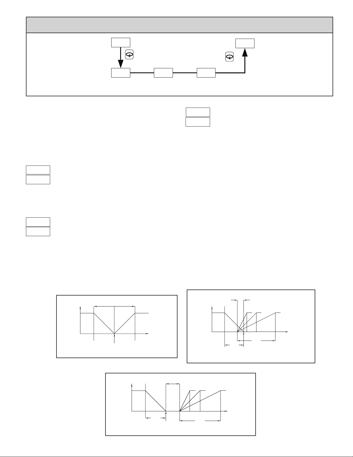
This defines the overlap area in which both heating and cooling are active
(negative value) or the deadband area between the bands (positive value). If a
heat/cool overlap is specified, the percent output power is the sum of the heat
power (O1) and the cool power (O2). If Relative Gain is zero, the cooling
output operates in the On/Off Control Mode, with the On/Off Control
Hysteresis in Output Module becoming the cooling output hysteresis.
The function of Deadband is illustrated in the Control Mode Explanations. For
most applications, set this parameter to 0.0 prior to starting Auto-Tune. After
the completion of Auto-Tune, this parameter may be changed.
RELATIVE GAIN
to
This defines the gain of the cooling relative to the heating. It is generally set
to balance the effects of cooling to that of heating. This is illustrated in the Heat/
Cool Relative Gain Figures. A value of 0.0 places the cooling output into On/
Off Control.
HEAT/COOL RELATIVE GAIN FIGURES
2X PROPORTIONAL
OUTPUT
POWER ( )
O1
+100%
%
SETPOINT
Heat/Cool Deadband = 0
BAND
COOLHEAT
OUTPUT
POWER ( )
O2
-100%
TEMPERATURE
DEADBAND
O1
+100%
%
POSITIVE VALUE
O1
+100%
OUTPUT
POWER ( )
%
RELATIVE GAIN
21 .5
DEADBAND
NEGATIVE VALUE
RELATIVE GAIN
RELATIVE GAIN = .5
HEAT
COOL
SETPOINT
Heat/Cool Deadband < 0
O2
-100%
.512
O2
-100%
TEMPERATURE
HEAT
SETPOINT
RELATIVE GAIN = .5
COOL
Heat/Cool Deadband > 0
19
TEMPERATURE
Page 20
7.5 module 9 FACtory ServiCe operAtionS ()
PARAMETER MENU
FACTORY
SERVICE CODE
CALIBRATION
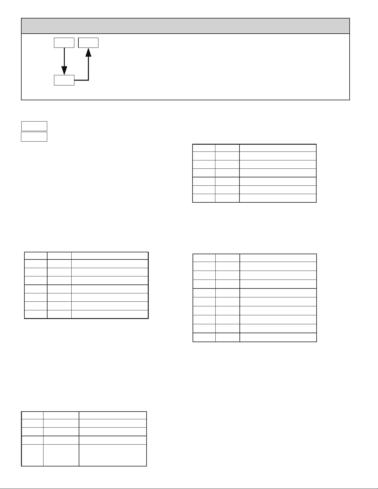
The controller is fully calibrated from the factory. Recalibration is
recommended every two years by qualified technicians using appropriate
equipment. Calibration may be performed by using the front panel.
Calibration may be aborted by disconnecting power to the controller before
exiting Factory Service Module . In this case, the existing calibration
settings remain in effect.
Note: Allow the controller to warm up for 30 minutes minimum and follow
the manufacturer’s warm-up recommendations for the calibration source or
measuring device.
Millivolt Calibration (CN63200)
Millivolt calibration requires a precision voltage source with an accuracy of
0.03% (or better) connected to terminals 8 (comm.) and 9 (+). When calibrating
the input, the millivolt calibration must be performed first, then the Cold Junction
or RTD Resistance.
PROMPT APPLY FRONT PANEL ACTION
Cold Junction (CN63200)
Cold Junction calibration requires a thermocouple of known accuracy of
types T, E, J, K, C or N (connected to terminals 8 and 9) and a calibrated
external reference thermocouple probe measuring in °C with resolution to
tenths. The two probes should be brought in contact with each other or in some
way held at the same temperature. They should be shielded from air movement
and allowed sufficient time to equalize in temperature. (As an alternative, the
CN63200 thermocouple may be placed in a calibration bath of known
temperature.) If performing the millivolt calibration prior, verify that the correct
input type is configured in Input Module before performing the following
procedure. (After the millivolt calibration the controller will default to type J.) If
using RTD only, the cold junction calibration need not be performed.
PROMPT COMPARE FRONT PANEL ACTION
0.0 mV
14.0 mV
28.0 mV
42.0 mV
56.0 mV
Top display to
external
reference
Press J until , press .
Press for , press .
After 5 seconds (minimum), press .
After 5 seconds (minimum), press .
After 5 seconds (minimum), press .
After 5 seconds (minimum), press .
After 5 seconds (minimum), press .
Press J until , press .
Press .
Press for , press .
Press or J to adjust the
bottom display until the top
process display matches the
external reference then press .
RTD Resistance (CN63200)
RTD calibration requires a precision 277.0 ohm resistor with an accuracy of
0.1 Ω (or better). Connect a jumper between terminals 9 and 10 with a 0 ohm
jumper between 9 and 8 at and the 277.0 ohm resistor between 9 and 8 at
. If using thermocouple only, the RTD calibration need not be performed.
FRONT PANEL ACTIONAPPLYPROMPT
0.0 ohm
277.0 ohm
Press J until , press .
Press .
Press .
Press for , press .
After 5 seconds (minimum), press .
After 5 seconds (minimum), press .
Input Calibration (CN63400)
Process calibration requires a precision signal source with an accuracy of
0.03% (or better) that is capable of generating 10.0 V connected to terminals 8
(COMM) and 9 (+10V) and 20.00 mA connected to terminals 8 (COMM) and
10 (20mA). The current calibration can be skipped by pressing at the not
applicable prompts if using the controller for process voltage only.
FRONT PANEL ACTIONAPPLYPROMPT
0.0 V
2.5 V
5.0 V
7.5 V
10.0 V
0.0 mA
20.0 mA
Press J until , press .
Press for , press .
After 5 seconds (minimum), press .
After 5 seconds (minimum), press .
After 5 seconds (minimum), press .
After 5 seconds (minimum), press .
After 5 seconds (minimum), press .
After 5 seconds (minimum), press .
After 5 seconds (minimum), press .
20
Page 21
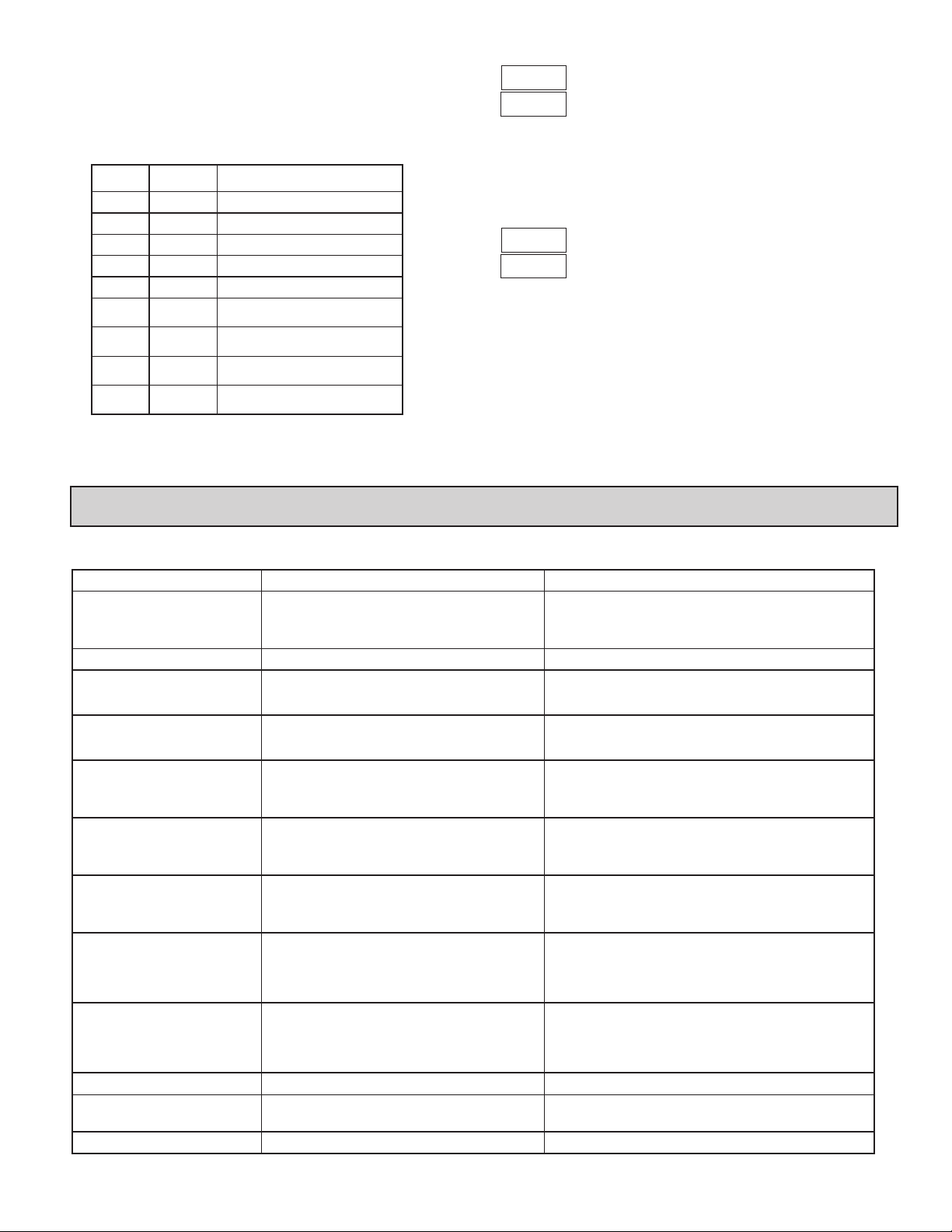
Analog Output Calibration (CN63200 and CN63400)
Set the controller Analog jumpers to the output type being calibrated.
Connect an external meter with an accuracy of 0.05% (or better) that is capable
of measuring 10.00 V or 20.00 mA to terminals 6 (+V/I) and 7 (-V/I). The
voltage or current calibration that is not being used must be skipped by pressing
until End appears.
PROMPT
EXTERNAL
METER
0.00 V
10.00 V
0.00 mA
20.00 mA
FRONT PANEL ACTION
Press J until , press .
Press .
Press . (CN63200 only)
Press . (CN63200 only)
Press for , press .
Press or J until external meter
matches listing, press .
Press or J until external meter
matches listing, press .
Press or J until external meter
matches listing, press .
Press or J until external meter
matches listing, press .
RESTORE FACTORY SETTINGS
Press and hold to display . Press . The controller will display
and then return to . Press
overwrite all user settings with Factory Settings.
NOMINAL CALIBRATION SETTINGS
L to return to the Display Loop. This will
Press and hold to display . Press . Press and hold to display
again. Press . The controller will then return to . Press
return to the Display Loop. This will not overwrite any user settings but will
erase the controller calibration values. This procedure does not require any
calibration signals nor external meters. This can be used to clear calibration
error flag .
CAUTION: This procedure will result in up to ±10% reading error and the
controller will no longer be within factory specifications. For this reason, this
procedure should only be performed if meter error is outside of this range to
temporarily restore operation until the unit can be accurately calibrated.
L to
troubleShooting
For further technical assistance, contact technical support.
PROBLEM CAUSE REMEDIES
NO DISPLAY
CONTROLLER NOT WORKING
IN DISPLAY
IN DISPLAY
or IN DISPLAY
IN DISPLAY (CN63200)
IN DISPLAY (CN63400)
IN TOP DISPLAY
IN TOP DISPLAY
IN DISPLAY (CN63200)
CONTROLLER SLUGGISH OR
NOT STABLE
IN DISPLAY
1. Power off.
2. Brown-out condition.
3. Loose connection or improperly wired.
4. Bezel assembly not fully seated into rear of controller.
1. Incorrect setup parameters. 1. Check setup parameters.
1. Loss of setup parameters due to noise spike or other
EMI event.
1. Loss of calibration parameters due to noise spike or
other EMI event.
1. Display value exceeds 4 digit display range.
2. Defective or miscalibrated cold junction circuit.
3. Loss of setup parameters.
4. Internal malfunction.
1. Probe disconnected.
2. Broken or burned-out probe.
3. Corroded or broken terminations.
4. Excessive process temperature.
1. Input exceeds range of controller.
2. Incorrect input wiring.
3. Defective transmitter.
4. Internal malfunction.
1. Input exceeds range of controller.
2. Temperature exceeds range of input probe.
3. Defective or incorrect transmitter or probe.
4. Excessive high temperature for probe.
5. Loss of setup parameters.
1. Input is below range of controller.
2. Temperature below range of input probe.
3. Defective or incorrect transmitter or probe.
4. Excessive low temperature for probe.
5. Loss of setup parameters.
1. RTD probe shorted. 1. Check wiring and/or replace RTD probe.
1. Incorrect PID values.
2. Incorrect probe location.
1. Control Output is damaged. 1. Return unit to factory for repair.
1. Check power.
2. Verify power reading.
3. Check connections.
4. Check installation.
1. Press F1 to escape, then check all setup parameters.
a. Check sensor input and AC line for excessive noise.
b. If fault persists, replace controller.
1. Press F1 to escape, then check controller accuracy.
a. Recalibrate controller. (See Factory Service Module code 77.)
b. Reset parameters to factory default settings.
1. Change resolution to display whole number and verify reading.
2. Perform cold junction calibration.
3. Check setup parameters.
4. Perform Input calibration.
1. Connect probe.
2. Replace probe.
3. Check connections.
4. Check process parameters.
1. Check input parameters.
2. Check input wiring.
3. Replace transmitter.
4. Perform input calibration.
1. Check input parameters.
2. Change to input sensor with a higher temperature range.
3. Replace transmitter or probe.
4. Reduce temperature.
5. Perform input calibration.
1. Check input parameters.
2. Change to input sensor with a lower temperature range.
3. Replace transmitter or probe.
4. Raise temperature.
5. Perform input calibration.
1. See PID control.
2. Evaluate probe location.
21
Page 22
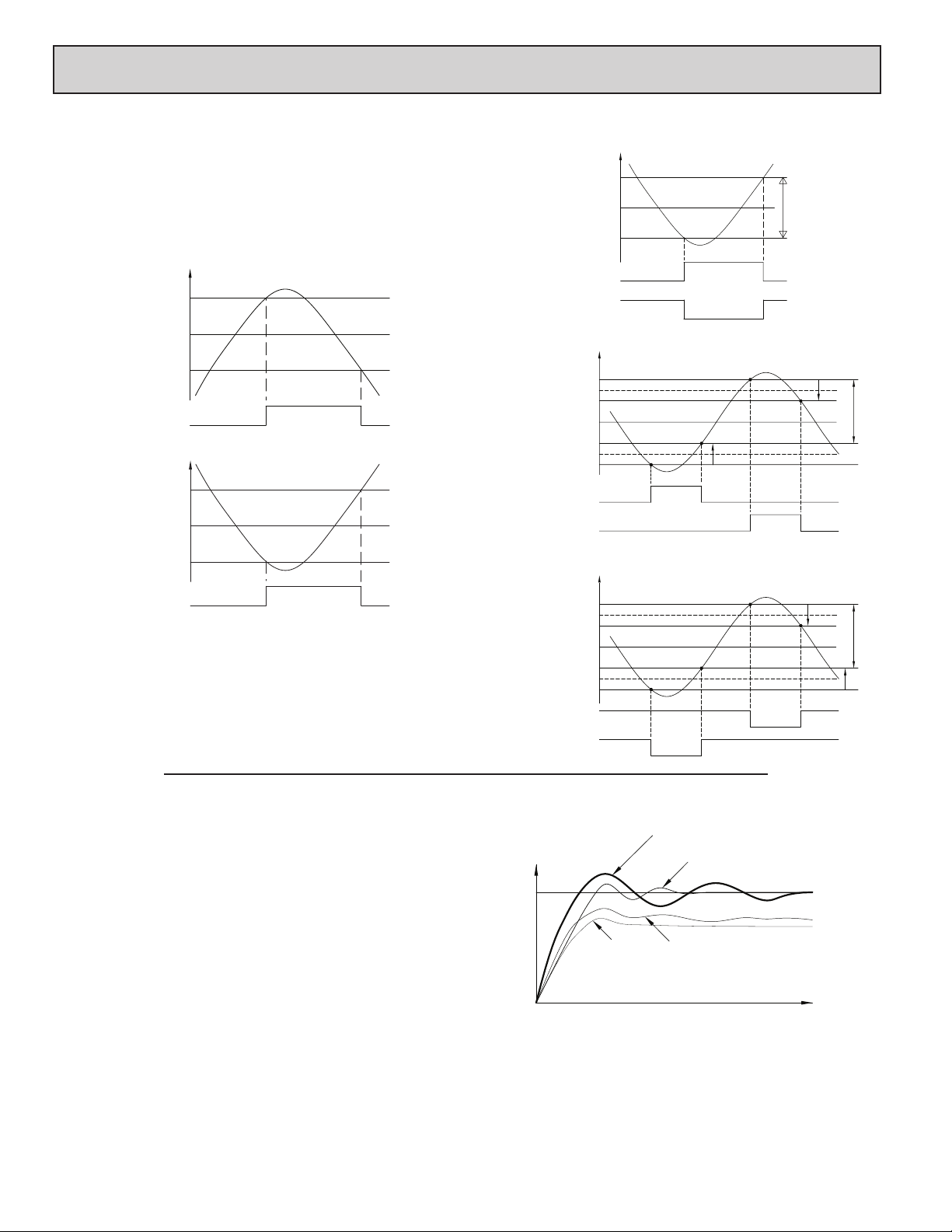
Control mode explAnAtionS
TIME
P & I
ON/OFF CONTROL
The controller operates in On/Off Control when the Proportional Band is set
to 0.0%. In this control mode, the process will constantly oscillate around the
setpoint value. The On/Off Control Hysteresis (balanced around the setpoint)
can be used to eliminate output chatter. Output O1 Control Action can be set to
reverse for heating (output on when below the setpoint) or direct for cooling
(output on when above the setpoint) applications.
ON/OFF CONTROL -
REVERSE OR DIRECT ACTING FIGURES
INPUT
SP + 1/2 CHYS
SP
SP - 1/2 CHYS
Output 1 (O1) :
INPUT
SP + 1/2 CHYS
SP
SP - 1/2 CHYS
Output 1 (O1) :
Note: CHYS in the On/Off Control Figures refers to the On/Off Control Hysteresis
) in parameter Module 2.
(
For heat and cool systems, O1 Control Action is set to reverse (heat) and the
Alarm 2 Action is set to cooling (O2). The Proportional Band is set to 0.0 and
the Relative Gain in Cooling to 0.0. The Deadband in Cooling sets the amount
of operational deadband or overlap between the outputs. The setpoint and the
On/Off Control Hysteresis applies to both O1 and O2 outputs. The hysteresis is
balanced in relationship to the setpoint and deadband value.
DIRECT ACTING
OFF
REVERSE ACTING
OFF
ON
ON
OFF
OFF
ON/OFF CONTROL - HEAT/COOL OUTPUT FIGURES
INPUT
HEAT/COOL DEADBAND (db2) = 0
SP + 1/2 CHYS
SP
SP - 1/2 CHYS
Output 1 (O1) :
Output 2 (O2) :
SP + 1/2 (db-2) + 1/2 CHYS
SP + 1/2 (db-2)
SP + 1/2 (db-2) - 1/2 CHYS
SP - 1/2 (db-2) + 1/2 CHYS
SP - 1/2 (db-2)
SP - 1/2 (db-2) - 1/2 CHYS
Output 1 (O1) :
Output 2 (O2) :
SP + 1/2 (db-2) + 1/2 CHYS
SP + 1/2 (db-2)
SP + 1/2 (db-2) - 1/2 CHYS
SP - 1/2 (db-2) + 1/2 CHYS
SP - 1/2 (db-2)
SP - 1/2 (db-2) - 1/2 CHYS
Output 1 (O1) :
Output 2 (O2) :
ON
INPUT
HEAT/COOL DEADBAND (db-2) > 0
SP
O1 OFF
INPUT
SP
O1 ON
O2 OFF
HEAT/COOL DEADBAND (db-2) < 0
O2 ON
O2 OFF
ON
OFF
CHYS
O1 OFF
O1 ON
O2 ON
OFFOFF
ON
O2 ON
O1 OFF
CHYS
CHYS
db-2
O2 OFF
CHYS
db-2
CHYS
O1 ON
PID CONTROL
In PID Control, the controller processes the input and then calculates a
control output power value by use of a modified Proportional Band, Integral
Time, and Derivative T ime control algorithm. The system is controlled with the
new output power value to keep the process at the setpoint. The Control Action
for PID Control can be set to reverse for heating (output on when below the
setpoint) or direct for cooling (output on when above the setpoint) applications.
For heat and cool systems, the heat (O1) and cool (O2) outputs are both used.
The PID parameters can be established by using Auto-Tune, or they can be
Manually tuned to the process.
22
INPUT
SP
TYPICAL PID RESPONSE CURVE
P & I & D
P & D
P only
Page 23
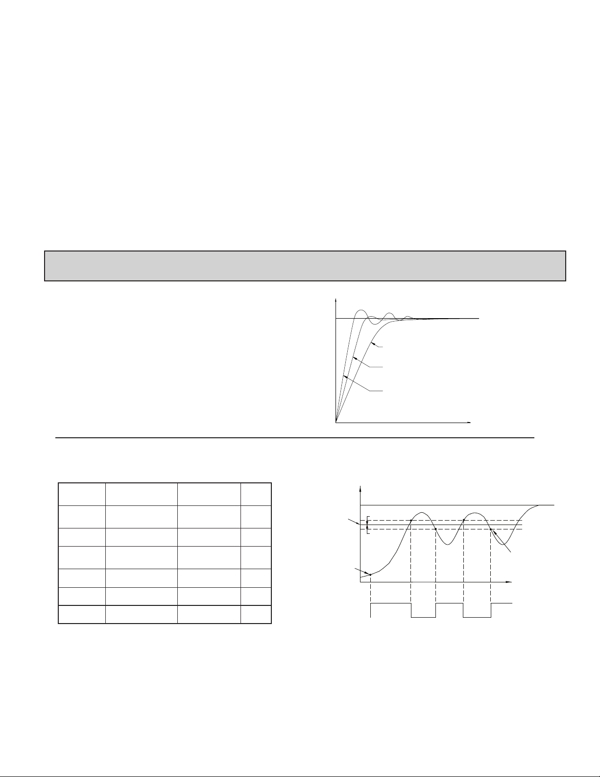
TIME PROPORTIONAL PID CONTROL
In Time Proportional applications, the output power is converted into output
On time using the Cycle Time. For example, with a four second cycle time and
75% power, the output will be on for three seconds (4 × 0.75) and off for
one second.
The cycle time should be no greater than 1/10 of the natural period of
oscillation for the process. The natural period is the time it takes for one
complete oscillation when the process is in a continuously oscillating state.
LINEAR PID CONTROL
In Linear PID Control applications, the Analog Output Assignment is set
to % Output Power, . The Analog Low Scaling, , is set to 0.0 and the
Analog High Scaling, , is set to 100.0. The Analog Output will then be
proportional to the PID calculated % output power for Heat or Cooling per the
Control Action . For example, with 0 VDC to 10 VDC (scaled 0 to 100%)
and 75% power, the analog output will be 7.5 VDC.
pid tuning explAnAtionS
MANUAL CONTROL MODE
In Manual Control Mode, the controller operates as an open loop system
(does not use the setpoint and process feedback). The user adjusts the percentage
of power through the % Power display to control the power for Output O1.
When Alarm 2 is configured for Cooling (O2), Manual operation provides 0 to
100% power to O1 (heating) and -100 to 0% power to O2 (Cooling). The Low
and High Output Power limits are ignored when the controller is in Manual.
MODE TRANSFER
When transferring the controller mode between Automatic and Manual, the
controlling outputs remain constant, exercising true “bumpless” transfer. When
transferring from Manual to Automatic, the power initially remains steady, but
Integral Action corrects (if necessary) the closed loop power demand at a rate
proportional to the Integral Time.
AUTOMATIC CONTROL MODE
In Automatic Control Mode, the percentage of output power is automatically
determined by PID or On/Off calculations based on the setpoint and process
feedback. For this reason, PID Control and On/Off Control always imply
Automatic Control Mode.
AUTO-TUNE
Auto-Tune is a user-initiated function that allows the controller to
automatically determine the Proportional Band, Integral Time, Derivative T ime,
Digital Filter, Control Output Dampening Time, and Relative Gain (Heat/Cool)
values based upon the process characteristics. The Auto-Tune operation cycles
the controlling output(s) at a control point three-quarters of the distance
between the present process value and the setpoint. The nature of these
oscillations determines the settings for the controller’s parameters.
Prior to initiating Auto-T une, it is important that the controller and system be
first tested. (This can be accomplished in On/Off Control or Manual Control
Mode.) If there is a wiring, system or controller problem, Auto-Tune may give
incorrect tuning or may never finish. Auto-Tune may be initiated at start-up,
from setpoint or at any other process point. However, ensure normal process
conditions (example: minimize unusual external load disturbances) as they will
have an effect on the PID calculations.
Start Auto-Tune
Below are the parameters and factory settings that affect Auto-Tune. If these
setting are acceptable then Auto-Tune can be started just by performing two
steps. If changes are needed, then they must be made before starting Auto-T une.
MODULEFACTORY SETTINGPARAMETERDISPLAY
Input Type
Digital Filtering
On/Off Control
Hysteresis
Auto-Tune Code
Deadband
Auto-Tune Access
1. Enter the Setpoint value in the Display Loop.
2. Initiate Auto-Tune by changing Auto-Tune Start to in the Hidden
Loop.
CN63200
CN63400
CN63200
CN63400
INPUT
SP
INPUT
SETPOINT
AUTO-TUNE
CONTROL
POINT
AUTO-TUNE
START
PHASE
OUTPUT 1 (O1) :
* - On/Off Control Hysteresis
AUTO-TUNE CODE FIGURE
2
TYPICAL RESPONSE CURVES WITH
1
AUTO-TUNE CODES 0 TO 2.
0
AUTO-TUNE OPERATION
(REVERSE ACTING)
1/2 CHYS *
1/2 CHYS *
Aut1 Aut4
ON
Aut2 Aut3
OFF
ON
TIME
AUTO-TUNE COMPLETE, PID
SETTINGS ARE CALCULATED
AND LOADED INTO MEMORY
TIME
OFF
Auto-Tune Progress
The controller will oscillate the controlling output(s) for four cycles. The
bottom display will flash the cycle phase number. Parameter viewing is
permitted during Auto-Tune. The time to complete the Auto-Tune cycles is
process dependent. The controller should automatically stop Auto-Tune and
store the calculated values when the four cycles are complete. If the controller
remains in Auto-Tune unusually long, there may be a process problem. AutoTune may be stopped by entering in Auto-Tune Start .
23
Page 24
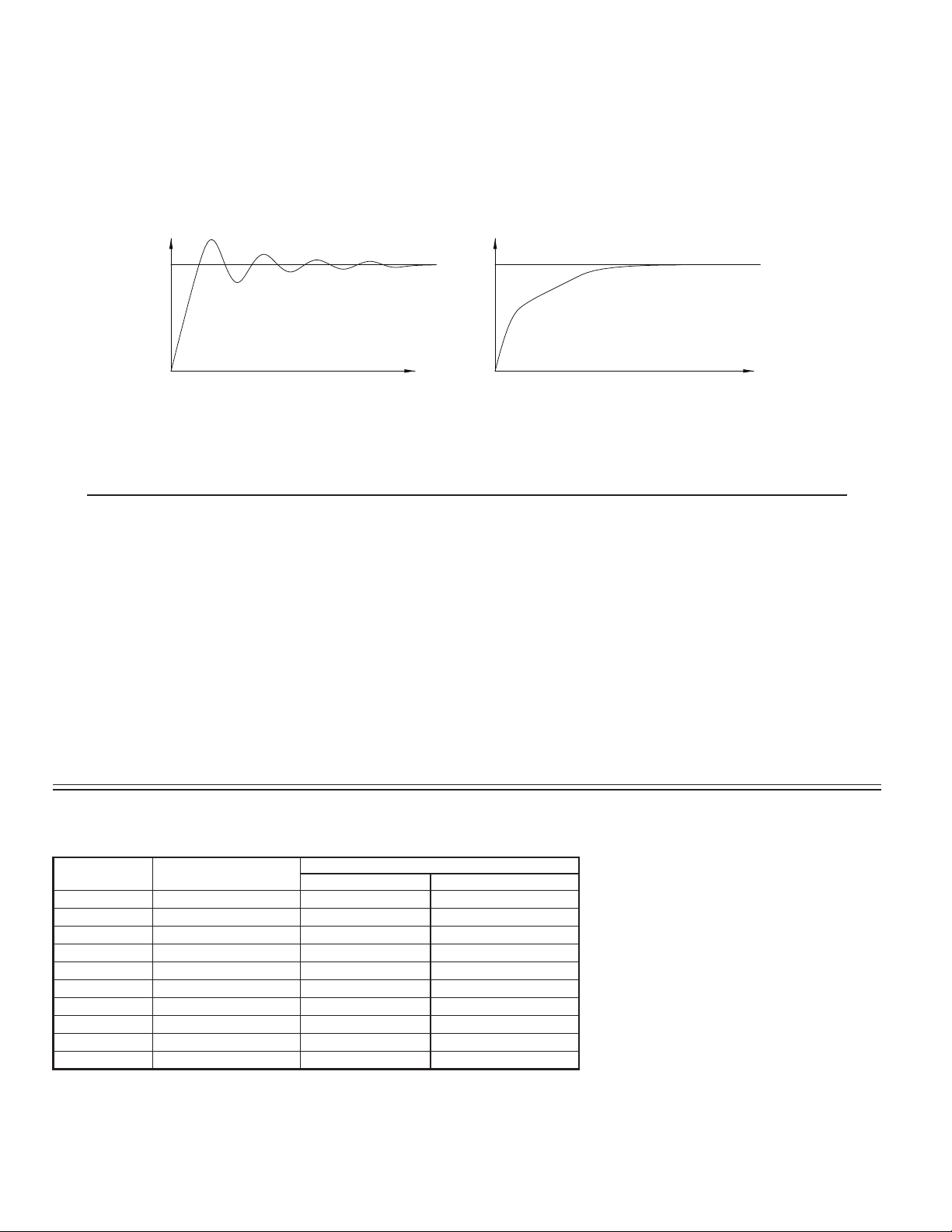
PID Adjustments
In some applications, it may be necessary to fine tune the Auto-Tune
calculated PID parameters. To do this, a chart recorder or data logging device is
needed to provide a visual means of analyzing the process. Compare the actual
process response to the PID response figures with a step change to the process.
Make changes to the PID parameters in no more than 20% increments from the
starting value and allow the process sufficient time to stabilize before evaluating
the effects of the new parameter settings.
PROCESS RESPONSE EXTREMES
OVERSHOOT AND OSCILLATIONS SLOW RESPONSE
INPUTINPUT
In some unusual cases, the Auto-Tune function may not yield acceptable
control results or induced oscillations may cause system problems. In these
applications, Manual Tuning is an alternative.
SP
TIME
TO DAMPEN RESPONSE:
- INCREASE PROPORTIONAL BAND.
- INCREASE INTEGRAL TIME.
- USE SETPOINT RAMPING.
- USE OUTPUT POWER LIMITS.
- RE-INVOKE AUTO-TUNE WITH A
HIGHER AUTO-TUNE CODE.
- INCREASE DERIVATIVE TIME.
- CHECK CYCLE TIME.
MANUAL TUNING
A chart recorder or data logging device is necessary to measure the time
between process cycles. This procedure is an alternative to the controller’s AutoTune function. It will not provide acceptable results if system problems exist.
1. Set the Proportional Band () to 10.0% for temperature models (CN63200)
and 100.0% for process models (CN63400).
2. Set both the Integral Time () and Derivative Time () to 0 seconds.
3. Set the Output Dampening Time () in Output Module to 0 seconds.
4. Set the Output Cycle Time [CYCt] in Output Module to no higher than
one-tenth of the process time constant (when applicable).
5. Place the controller in Manual Control Mode in the Hidden Loop
and adjust the % Power to drive the process value to the Setpoint value.
Allow the process to stabilize after setting the % Power. Note: must be
set to in Parameter Lockouts Module .
6. Place the controller in Automatic () Control Mode in the Hidden
Loop. If the process will not stabilize and starts to oscillate, set the
Proportional Band two times higher and go back to Step 5.
SP
TIME
TO QUICKEN RESPONSE:
- DECREASE PROPORTIONAL BAND.
- DECREASE INTEGRAL TIME.
- INCREASE OR DEFEAT SETPOINT RAMPING.
- EXTEND OUTPUT POWER LIMITS.
- RE-INVOKE AUTO-TUNE WITH A
LOWER AUTO-TUNE CODE.
- DECREASE DERIVATIVE TIME.
7. If the process is stable, decrease Proportional Band setting by two times and
change the Setpoint value a small amount to excite the process. Continue
with this step until the process oscillates in a continuous nature.
8. Fix the Proportional Band to three times the setting that caused the oscillation
in Step 7.
9. Set the Integral Time to two times the period of the oscillation.
10. Set the Derivative Time to 1/8 (0.125) of the Integral Time.
11. Set the Output Dampening T ime to 1/40 (0.025) the period of the oscillation.
PART NUMBERS
2 ALARMS & USER INPUTMAIN CONTROL
* Analog out may be used for retransmitted signals. When using analog output for retransmitted signals,
AL1 becomes main control O1, if selected for heating in the analog out models.
PART NUMBERS
85 to 250 VAC18-36 VDC/24 VAC
CN63200-R1CN63200-R1-LV—Relay
CN63200-R1-ALCN63200-R1-AL-LVYesRelay
CN63200-DC1CN63200-DC1-LV—Logic/SSR
CN63200-DC1-ALCN63200-DC1-AL-LVYesLogic/SSR
CN63200-F1-ALCN63200-F1-AL-LVYesAnalog Out *
CN63400-R1CN63400-R1-LV—Relay
CN63400-R1-ALCN63400-R1-AL-LVYesRelay
CN63400-DC1CN63400-DC1-LV—Logic/SSR
CN63400-DC1-ALCN63400-DC1-AL-LVYesLogic/SSR
CN63400-F1-ALCN63400-F1-AL-LVYesAnalog Out *
24
Page 25

PARAMETER VALUE CHART
Programmer:______________________Date:_________
Controller Number:_______ Security Code:_______
DISPLAY LOOP
DISPLAY PARAMETER FACTORY SETTING USER SETTING
CN63200
*
*
*
*
*
* Factory Setting places these parameters in the Hidden Loop (set to in
HIDDEN LOOP
INPUT MODULE ( ) CN63200 ONLY
INPUT MODULE ( ) CN63400 ONLY
SETPOINT VALUE SP1
SETPOINT VALUE SP2
OUTPUT POWER PERCENT
PROPORTIONAL BAND
INTEGRAL TIME
DERIVATIVE TIME
ALARM 1 VALUE
ALARM 2 VALUE
Lockout Module
.
SETPOINT SELECT
SETPOINT RAMP RATE
CONTROL MODE TRANSFER
AUTO-TUNE START
INPUT TYPE
TEMPERATURE SCALE
DECIMAL RESOLUTION
DIGITAL FILTERING
SHIFT/OFFSET
SETPOINT LOW LIMIT
SETPOINT HIGH LIMIT
USER INPUT FUNCTION
F1 KEY FUNCTION
INPUT TYPE
PERCENT ANNUNCIAT OR
DECIMAL RESOLUTION
ROUNDING INCREMENT
DIGITAL FILTERING
DISPLAY VALUE SCALING 1
INPUT VALUE SCALING 1
DISPLAY VALUE SCALING 2
INPUT VALUE SCALING 2
SETPOINT LOW LIMIT
SETPOINT HIGH LIMIT
USER INPUT FUNCTION
F1 KEY FUNCTION
CN63400
CN63200
CN63400
CN63200
CN63400
CN63200
CN63400
CN63200
CN63400
USER SETTINGFACTORY SETTINGPARAMETERDISPLAY
USER SETTINGFACTORY SETTINGPARAMETERDISPLAY
USER SETTINGDISPLAY PARAMETER FACTORY SETTING
OUTPUT MODULE ()
FACTORY
LOCKOUT MODULE ()
ALARM MODULE ()
COOLING MODULE ()
CYCLE TIME
CONTROL ACTION
OUTPUT POWER LOWER LIMIT
OUTPUT POWER UPPER LIMIT
SENSOR FAIL POWER PRESET
OUTPUT POWER DAMPENING
ON/OFF CONTROL HYSTERESIS
AUTO-TUNE CODE
ANALOG OUTPUT RANGE
ANALOG OUTPUT ASSIGNMENT
ANALOG UPDATE TIME
ANALOG LOW SCALING
ANALOG HIGH SCALING
SETPOINT ACCESS
OUTPUT POWER ACCESS
PID VALUE ACCESS
ALARM VALUE ACCESS
ACCESS CODE
SETPOINT SELECT ACCESS
SETPOINT RAMP ACCESS
TRANSFER CONTROL ACCESS
AUTO-TUNE ACCESS
RESET ALARMS ACCESS
ALARM 1 ACTION
ALARM 1 ANNUNCIATOR
ALARM 1 RESET MODE
ALARM 1 STANDBY
ALARM 1 VALUE
ALARM 2 ACTION
ALARM 2 ANNUNCIATOR
ALARM 2 RESET MODE
ALARM 2 STANDBY
ALARM 2 VALUE
ALARM 1 & 2 HYSTERESIS
PARAMETERDISPLAY
CYCLE TIME
RELATIVE GAIN
DEADBAND
SETTING
FACTORY
SETTING
FACTORY
SETTING
FACTORY
SETTING
USER SETTINGDISPLAY PARAMETER
CN63200
CN63400
CN63200
CN63400
USER SETTINGDISPLAY PARAMETER
USER SETTINGDISPLAY PARAMETER
CN63200
CN63400
USER SETTING
25
Page 26
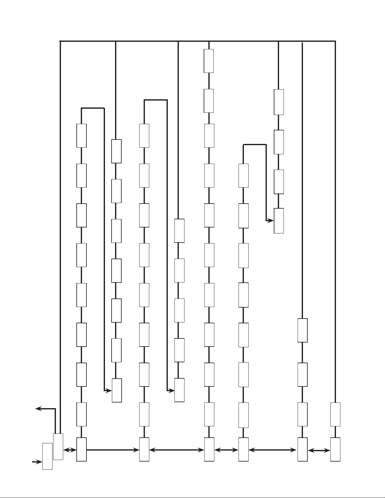
Cn63200 & Cn63400 progrAmming overvieW
Access
Reset Alarms
- CN63400 only
- CN63200 only
Auto-Tune
Off/On Access
Hysteresis
Alarm 1 & 2
Advances to the next
module, then changes
parameter selection/value.
J
Enters displayed module,
then advances to the next
parameter.
Input
Display
Digital
Rounding
Decimal
Value 1
Value 1
Filtering
Increment
Resolution
F1 Key
User Input
Setpoint
Shift/Offset Setpoint
Function
Function
High Limit
Low Limit
Code
Auto-Tune
Hysteresis
On/Off Control
Dampening
Output Power
Sensor Fail
Power Preset
High Limit
Output Power
Scaling
Analog High
Scaling
Analog Low
Update Time
Analog Output
Access
Transfer
Auto/Manual
Access
Setpoint
Ramp Rate
Select
Access
Setpoint
Code
Access
Alarm
Values
Access
Alarm 2
Alarm 2
Alarm 1
Alarm 1
Annunciator
Action
Value
Standby
Alarm 2
Alarm 2
Alarm 2
Value
Standby
Reset Mode
Ends and returns to
start of Display Loop.
L
Parameter availability is model and program dependent.
LOOP
DISPLAY
LOOP
HIDDEN
Temp
Percent
Input
Scale
Symbol
Type
Input
Display
Value 2
Value 2
Low Limit
Output Power
Action
Control
Time
Cycle
Assignment
Analog Output
Analog
Output Range
26
Access
PID Values
Power
Output
Access
Access
Setpoint
Alarm 1
Alarm 1
Alarm 1
Reset Mode
Annunciator
Action
Heat/Cool
Deadband/Overlap
Cooling
Relative Gain
Cooling
Cycle Time
Factory
Service Code
Page 27

WARRANTY/DISCLAIMER
OMEGA ENGINEERING, INC. warrants this unit to be free of defects in materials and workmanship for a
period of 13 months from date of purchase. OMEGA’s WARRANTY adds an additional one (1) month
grace period to the normal one (1) year product warranty to cover handling and shipping time. This
ensures that OMEGA’s customers receive maximum coverage on each product.
If the unit malfunctions, it must be returned to the factory for evaluation. OMEGA’s Customer Service
Department will issue an Authorized Return (AR) number immediately upon phone or written request.
Upon examination by OMEGA, if the unit is found to be defective, it will be repaired or replaced at no
charge. OMEGA’s WARRANTY does not apply to defects resulting from any action of the purchaser,
including but not limited to mishandling, improper interfacing, operation outside of design limits,
improper repair, or unauthorized modification. This WARRANTY is VOID if the unit shows evidence of
having been tampered with or shows evidence of having been damaged as a result of excessive
corrosion; or current, heat, moisture or vibration; improper specification; misapplication; misuse or other
operating conditions outside of OMEGA’s control. Components in which wear is not warranted, include
but are not limited to contact points, fuses, and triacs.
OMEGA is pleased to offer suggestions on the use of its various products. However,
OMEGA neither assumes responsibility for any omissions or errors nor assumes liability for
any damages that result from the use of its products in accordance with information
provided by OMEGA, either verbal or written. OMEGA warrants only that the parts
manufactured by the company will be as specified and free of defects. OMEGA MAKES NO
OTHER WARRANTIES OR REPRESENTATIONS OF ANY KIND WHATSOEVER, EXPRESSED OR
IMPLIED, EXCEPT THAT OF TITLE, AND ALL IMPLIED WARRANTIES INCLUDING ANY
WARRANTY OF MERCHANTABILITY AND FITNESS FOR A PARTICULAR PURPOSE ARE
HEREBY DISCLAIMED. LIMITATION OF LIABILITY: The remedies of purchaser set forth
herein are exclusive, and the total liability of OMEGA with respect to this order, whether
based on contract, warranty, negligence, indemnification, strict liability or otherwise, shall
not exceed the purchase price of the component upon which liability is based. In no event
shall OMEGA be liable for consequential, incidental or special damages.
CONDITIONS: Equipment sold by OMEGA is not intended to be used, nor shall it be used: (1) as a “Basic
Component” under 10 CFR 21 (NRC), used in or with any nuclear installation or activity; or (2) in medical
applications or used on humans. Should any Product(s) be used in or with any nuclear installation or
activity, medical application, used on humans, or misused in any way, OMEGA assumes no responsibility
as set forth in our basic WARRANTY/DISCLAIMER language, and, additionally, purchaser will indemnify
OMEGA and hold OMEGA harmless from any liability or damage whatsoever arising out of the use of the
Product(s) in such a manner.
RETURN REQUESTS/INQUIRIES
Direct all warranty and repair requests/inquiries to the OMEGA Customer Service Department. BEFORE
RETURNING ANY PRODUCT(S) TO OMEGA, PURCHASER MUST OBTAIN AN AUTHORIZED RETURN (AR)
NUMBER FROM OMEGA’S CUSTOMER SERVICE DEPARTMENT (IN ORDER TO AVOID PROCESSING
DELAYS). The assigned AR number should then be marked on the outside of the return package and on
any correspondence.
The purchaser is responsible for shipping charges, freight, insurance and proper packaging to prevent
breakage in transit.
FOR WARRANTY RETURNS, please have the
following information available BEFORE
contacting OMEGA:
1. Purchase Order number under which the product
was PURCHASED,
2. Model and serial number of the product under
warranty, and
3. Repair instructions and/or specific problems
relative to the product.
OMEGA’s policy is to make running changes, not model changes, whenever an improvement is possible. This affords our
customers the latest in technology and engineering.
OMEGA is a registered trademark of OMEGA ENGINEERING, INC.
© Copyright 2006 OMEGA ENGINEERING, INC. All rights reserved. This document may not be copied, photocopied,
reproduced, translated, or reduced to any electronic medium or machine-readable form, in whole or in part, without the
prior written consent of OMEGA ENGINEERING, INC.
FOR NON-WARRANTY REPAIRS, consult OMEGA
for current repair charges. Have the following
information available BEFORE contacting OMEGA:
1. Purchase Order number to cover the COST of the
repair,
2. Model and serial number of the product, and
3. Repair instructions and/or specific problems
relative to the product.
27
Page 28

Where Do I Find Everything I Need for
Process Measurement and Control?
OMEGA…Of Course!
Shop online at omega.com
TEMPERATURE
] Thermocouple, RTD & Thermistor Probes, Connectors, Panels & Assemblies
] Wire: Thermocouple, RTD & Thermistor
] Calibrators & Ice Point References
] Recorders, Controllers & Process Monitors
] Infrared Pyrometers
PRESSURE, STRAIN AND FORCE
] Transducers & Strain Gages
] Load Cells & Pressure Gages
] Displacement Transducers
] Instrumentation & Accessories
FLOW/LEVEL
] Rotameters, Gas Mass Flowmeters & Flow Computers
] Air Velocity Indicators
] Turbine/Paddlewheel Systems
] Totalizers & Batch Controllers
pH/CONDUCTIVITY
] pH Electrodes, Testers & Accessories
] Benchtop/Laboratory Meters
] Controllers, Calibrators, Simulators & Pumps
] Industrial pH & Conductivity Equipment
DATA ACQUISITION
] Data Acquisition & Engineering Software
] Communications-Based Acquisition Systems
] Plug-in Cards for Apple, IBM & Compatibles
] Datalogging Systems
] Recorders, Printers & Plotters
HEATERS
] Heating Cable
] Cartridge & Strip Heaters
] Immersion & Band Heaters
] Flexible Heaters
] Laboratory Heaters
ENVIRONMENTAL
MONITORING AND CONTROL
] Metering & Control Instrumentation
] Refractometers
] Pumps & Tubing
] Air, Soil & Water Monitors
] Industrial Water & Wastewater Treatment
] pH, Conductivity & Dissolved Oxygen Instruments
 Loading...