

Page 1
Using This Quick Start Manual
NC
L
ALM1
NO C
(+)
N(-)
NC
ALM2
NO C
19
N
L
SW
Fuse
SW
+
-
Or
DC POWER OPTION
90 – 240Vac
9 – 36Vdc
AC POWER
Fuse
NC
L
ALM1
NO C
(+)
N(-)
NC
ALM2
NO C
19
Fuse
Fuse
Load
Load
Supplemental
Ground
3
2
START HERE
1
Panel
Bezel
Case Slide Screw
Side View
User
Accessible
Behin d Pane l
Panel Cutout
92mm
92mm
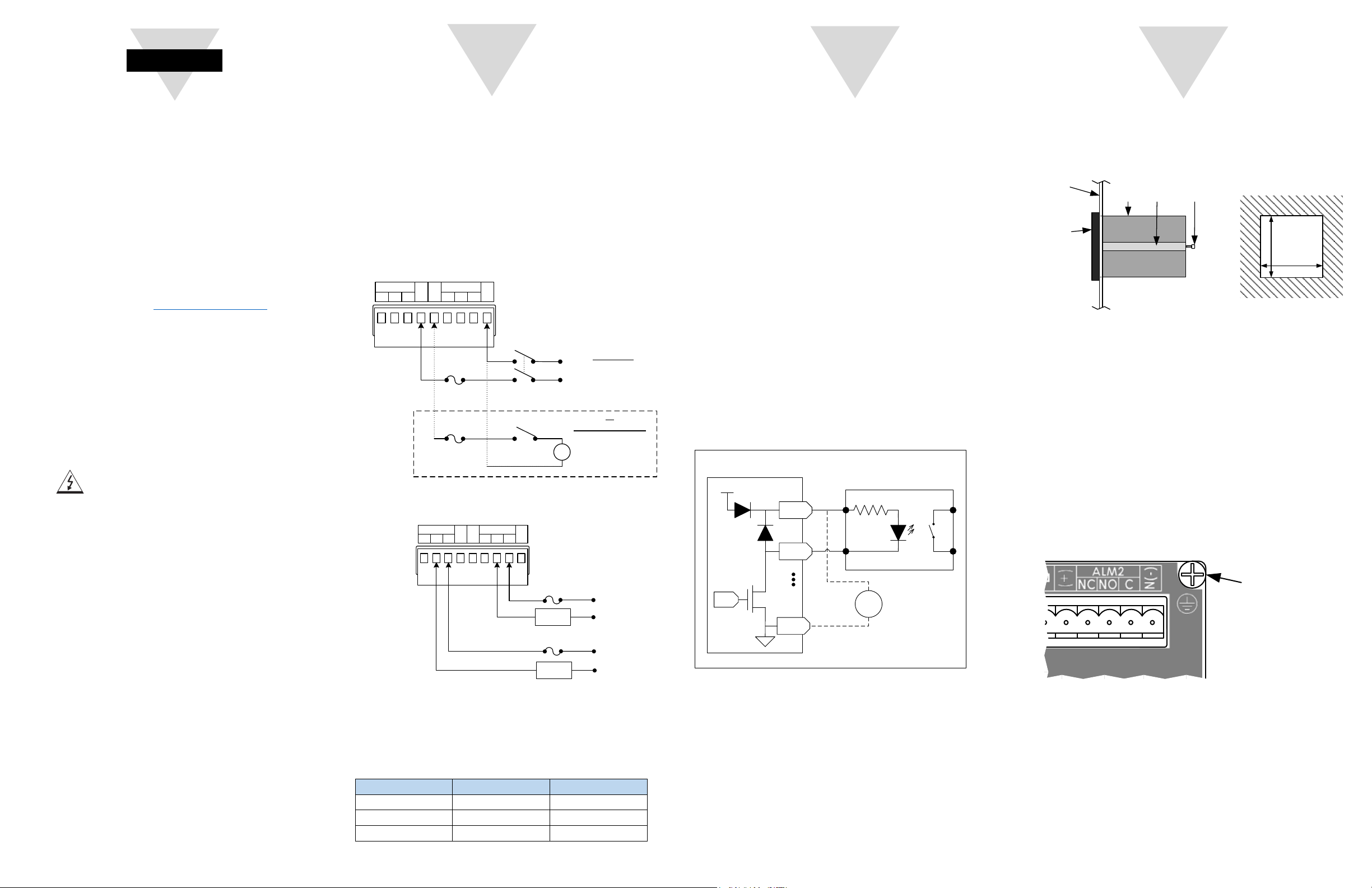
Figure 4 – Panel Mounting
Use this Quick Start Manual to set up your CN616A Multi
Zone Controller. This guide will cover:
Required Tool and Equipment
Before Installing the CN616A make sure you have the
following Items:
Connecting Inputs and Outputs
Connect Input sensors to the lower terminals Marked Zone 1
though Zone 6 (Z1 – Z6) on the rear panel.
Mounting
• Required Tools and Equipment
• Wiring the device
• Connecting Inputs and Outputs
• Mounting
• Running the Unit
• Changing the Sensor Type
• Available Functions
For complete information on all setup options see the
user manual available at omega.com/manuals.
SAFETY CONSIDERATION
The instrument is a device protected in accordance with UL
61010:2010 Electrical Safety Requirements for Electrical
Equipment for Measurement, Control and Laboratory. The
device has no power-on switch. Installations must include a
switch or circuit breaker that is compliant to IEC 947-1 and
947-3. It must be suitably located to be easily reached and
marked as the disconnecting device for the equipment.
Use copper conductors only, minimum 20 AWG, UL Rated, for
power connection. Insulation must be rated for at least 85C and
600V.
Do NOT connect AC power to your device until you have
completed all input and output connections. This device is a
panel mount device protected in accordance with Class I of
EN61010 (115/230 AC power connections), Class III for the DC
power option (9-36Vdc). It must be installed by a trained
electrician with corresponding qualifications. Failure to follow all
instructions and warnings may result in injury.
This device is not designed for use in, and should not be used
for, patient-connected applications.
SAFETY:
• Do not exceed the voltage rating on the label located on the
device housing.
• Always disconnect power before changing signal and power
connections.
• Do not use this instrument on a work bench without its case.
• Do not operate this instrument in flammable or explosive
atmospheres.
• Do not expose this instrument to rain or moisture.
EMC:
• Whenever EMC is an issue use shielded cables.
• Never run signal and power wires in the same conduit.
• Use signal wire connections with twisted-pair cables.
• If EMC problems occur Install Ferrite Bead(s) on signal wires
close to the instrument.
CAUTION: Risk of electric shock.
• Suitable Panel with 92x92mm cutout
• Philips and Flathead Screwdriver
• Appropriate wiring and fuses for your installation
• Sensors (TC, RTD, or Process)
Wiring the Device
Figure 1 – Main Power Wiring
Figure 2 – Alarm Relay Wiring
CAUTION: Use only provided terminals.
Torque all connections to 0.5-0.6Nm.
Table 1 – Fuse Values
Input Power Input Fuse Alarm Fuse
115Vac 25mA 5A
230Vac 25mA 5A
9-36VDC 300mA 3A
When connecting sensors follow the polarity indicated on the
rear panel. For Thermocouples the Negative wire is Red (NA) or
White (IEC 584-3). For Process Inputs the Negative terminal is
Return.
Note: All input terminals share a common internal Return
connection. Ensure that all sensors share a common Return or
are fully isolated.
Note: Absolute Maximum 3.3V (Process Voltage) or 30mA
(Process Current).
Connect Output drivers to the upper set of terminals. The
CN616A has 6 Common Drain outputs intended to drive
external SSRs. The outputs are Active Low and require an
external pullup. Each output is rated for 3.3Vdc to 36Vdc. An
internal 5Vdc supply is available for convenience and is rated
for 25mA per channel. Refer to the diagram below for the most
common connection options.
Output Connector
5V
External SSR
DC
Input
Output
Z1
Optional External
PWM
+
-
Supp ly
3.3V to 36V
C
Figure 3 – Output Wiring
When using an optional external power supply:
• If the power supply is less than 5V do not connect to the
DC terminals of the output connector as this may cause
back feeding of the power supply.
• Note that the Common terminals connect to the input
ground. Ensure the inputs and the power supply share a
common ground or are fully isolated.
• Using the dimensions from the panel cutout diagram shown
above, cut an opening in the front panel
• Remove the two screws that secure the mounting slides and
remove the slides.
• Insert the unit into the cutout from the front side of the
panel. Reinstall the two slides and two screws.
• Ensure that the unit is properly grounded to the panel
which should be earth grounded.
• Use the supplementary ground point indicated on the rear
panel if a good ground connection cannot be maintaine
from the mounting slides alone. A rin
g terminal is provided
d
for this purpose.
Figure 5 – Supplemental Ground Point
Page 2
Running the Unit
Item
Description
Item
Description
1
Main Display
5
Select Button
2
Zone Display
6
Function Display
3
Advance Button
7
Unit/Mode Indicator
4
Increment Button
Func
Description
Func
Description
70
Function Select
71
Model Setup Group
73
Control Setup
31
Zone Enable
41
Cycle Time
32
Password Enable
42
Hysteresis
33
Input and Alarm
43
PID Enable
34
Modbus Address
44
Proportional Gain
35
Zone Display Time
45
Integral Gain
81
Power-Up State
46
Derivative Gain
82
Alarm Relay 1
47
Control Direction
83
Alarm Relay 2
48
Control Mode
84
Serial Configuration
74
Segment Control
85
mA/mV Low Scaling
75
Segment Edit
86
mA/mV High Scaling
##
Segment ## (01 to 20)
72
Setpoints and Alarms
76
Autotune Setpoint
36
Absolute Setpoint
77
Run Autotune
37
High Alarm Setpoint
78
Calibration
38
Low Alarm Setpoint
79
Start Profile
ºC
ºF
mA
mV
Function
Zone
1
2
3
7
6
5
4
4
5
Available Functions
The current Function is always displayed in the Function
Menu. While in Run Mode Press to enter Function
select Mode.
Function select mode allows for full configuration of the
device. In Function select mode the desired Function to
edit is shown in the Main Display. Press to increment the
Function. Press to enter the Selected Menu
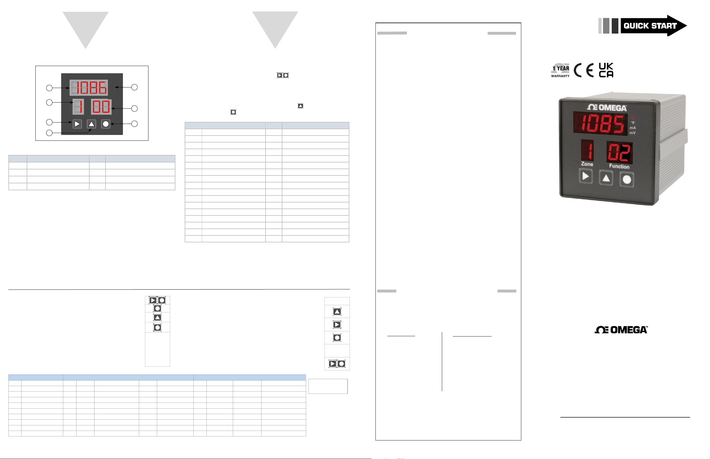
Figure 6 – Front Panel Diagram
When power is applied to the unit it automatically enters
Run mode, sequentially scanning each active zone and
activating alarms and outputs if required. The Main display
shows the measured value of the indicated zone.
The default sensor type is a K-type thermocouple. Please
see the section below to select the correct sensor.
By default, the outputs are set to On/Off control in the
Reverse direction (Heating) and the Setpoint for each
zone is zero. To change the setpoint use Function 36 in
submenu 72.
For more detailed information on each Function please
refer to the user Manual.
Table 2 – Device Configuration
Changing the sensor type:
• Enter Function Select Mode using:
• Enter Function 71 using the select button.
• 31 Appears on the Display. Increment the
selected function to 33.
•
Enter Function 33 using the Select Button
Function 33 is shown in the Function
•
Display and the current settings are shown
in the Main Display.
• Refer to the Device Configuration table
below to determine the desired settings.
Digit 1 Digit 2 Digit 3 Digit 4 (Function depends on Digit 3)
Alarm Type Unit Alarm Latch Input Type TC Type RTD Type Decimal Points*
0 High 0 C Latching 0 TC 0 B Pt100 0
1 Low 1 F Latching 1 RTD2 1 C Ni120 1
2 High / Low 2 C Non-Latching 2 E Cu10 2
3 Off 3 F Non-Latching 3 mA 3 J 3
4 User 4 mV 4 K
Please Note: Digit 4 is dependent upon the “Input Type” selected under Digit 3.
Ex: If “TC” is selected under “Input Type” under Digit 3, Digit 4 becomes one of the following “B, C, E, J, etc.” under “TC Type.”
• Digit 1 flashes to indicate it can be changed.
• Use the Increment button to change the
digit
• Use the Advance button to move to the next
Digit
• Once all changes are made use the Select
Button to save the settings.
• The unit returns to Function Select Mode
and 31 is shown in the Main Display
• Use the escape button combination twice to
return to run mode.
5 R
6 S
7 T
8 N
*Only Available
in mA/mV
mode.
WARRANTY/DISCLAIMER
OMEGA ENGINEERING, INC. warrants this unit to be free of defects
in materials and workmanship for a period of 61 months from
date of purchase. OMEGA’s WARRANTY adds an additional one (1)
month grace period to the normal five (5) year product warranty
to cover handling and shipping time. This ensures that OMEGA’s
customers receive maximum coverage on each product.
If the unit malfunctions, it must be returned to the factory for evaluation. OMEGA’s Customer Service Department will issue an Authorized
Return (AR) number immediately upon phone or written request.
Upon examination by OMEGA, if the unit is found to be defective, it
will be repaired or replaced at no charge. OMEGA’s WARRANTY does
not apply to defects resulting from any action of the purchaser, including but not limited to mishandling, improper interfacing, operation
outside of design limits, improper repair, or unauthorized modification. This WARRANTY is VOID if the unit shows evidence of having
been tampered with or shows evidence of having been damaged as a
result of excessive corrosion; or current, heat, moisture or vibration;
improper specification; misapplication; misuse or other operating
conditions outside of OMEGA’s control. Components in which wear
is not warranted, include but are not limited to contact points, fuses,
and triacs.
OMEGA is pleased to offer suggestions on the use of its various products. However, OMEGA neither assumes responsibility for any omissions or errors nor assumes liability for any
damages that result from the use if its products in accordance
with information provided by OMEGA, either verbal or written. OMEGA warrants only that the parts manufactured by
the company will be as specified and free of defects. OMEGA
MAKES NO OTHER WARRANTIES OR REPRESENTATIONS OF
ANY KIND WHATSOEVER, EXPRESSED OR IMPLIED, EXCEPT
THAT OF TITLE, AND ALL IMPLIED WARRANTIES INCLUDING
ANY WARRANTY OF MERCHANTABILITY AND FITNESS
FOR A PARTICULAR PURPOSE ARE HEREBY DISCLAIMED.
LIMITATION OF LIABILITY: The remedies of purchaser set
forth herein are exclusive, and the total liability of OMEGA
with respect to this order, whether based on contract, warranty, negligence, indemnification, strict liability or otherwise,
shall not exceed the purchase price of the component upon
which liability is based. In no event shall OMEGA be liable for
consequential, incidental or special damages.
CONDITIONS: Equipment sold by OMEGA is not intended to be used,
nor shall it be used: (1) as a “Basic Component” under 10 CFR 21 (NRC),
used in or with any nuclear installation or activity; or (2) in medical applications or used on humans. Should any Product(s) be used in or with
any nuclear installation or activity, medical application, used on humans,
or misused in any way, OMEGA assumes no responsibility as set forth
in our basic WARRANTY/DISCLAIMER language, and, additionally,
purchaser will indemnify OMEGA and hold OMEGA harmless from any
liability or damage whatsoever arising out of the use of the Product(s)
in such a manner.
RETURN REQUESTS/INQUIRIES
Direct all warranty and repair requests/inquiries to the OMEGA
Customer Service Department. BEFORE RETURNING ANY
PRODUCT(S) TO OMEGA, PURCHASER MUST OBTAIN AN
AUTHORIZED RETURN (AR) NUMBER FROM OMEGA’S CUSTOMER
SERVICE DEPARTMENT (IN ORDER TO AVOID PROCESSING
DELAYS). The assigned AR number should then be marked on the
outside of the return package and on any correspondence.
FOR WARRANTY RETURNS,
please have the following
information available BEFORE
contacting OMEGA:
1.
Purchase Order number
under which the product
was PURCHASED,
2.
Model and serial number of the
product under warranty, and
3.
Repair instructions and/or
specific problems relative
to the product.
OMEGA’s policy is to make running changes, not model changes,
whenever an improvement is possible. This affords our customers
the latest in technology and engineering.
OMEGA is a trademark of OMEGA ENGINEERING, INC.
© Copyright 2018 OMEGA ENGINEERING, INC. All rights reserved.
This document may not be copied, photocopied, reproduced,
translated, or reduced to any electronic medium or machine-readable
form, in whole or in part, without the prior written consent of OMEGA
ENGINEERING, INC.
FOR NON-WARRANTY REPAIRS,
consult OMEGA for current repair
charges. Have the following
information available BEFORE
contacting OMEGA:
1.
Purchase Order number to cover
the COST of the repair or
calibration,
2.
Model and serial number of the
product, and
3.
Repair instructions and/or specific
problems relative to the product.
MQS5807/1122
For complete product manual:
www.omega.com/manuals/manualpdf/M5704.pdf
TM
CN616A
Multi Zone Controller
omega.com [email protected]
Omega Engineering, Inc:
800 Connecticut Ave. Suite 5N01, Norwalk, CT 06854, USA
Toll-Free: 1-800-826-6342 (USA & Canada only)
Customer Service: 1-800-622-2378 (USA & Canada only)
Engineering Service: 1-800-872-9436 (USA & Canada only)
Tel: (203) 359-1660
e-mail: [email protected]
Omega Engineering,
Limited:
1 Omega Drive, Northbank,
Irlam Manchester M44 5BD
United Kingdom
For Other Locations Visit omega.com/worldwide
The information contained in this document is believed to be correct, but
OMEGA accepts no liability for any errors it contains, and reserves the right to
alter specifications without notice.
Fax: (203) 359-7700
Omega Engineering,
GmbH:
Daimlerstrasse 26 75392
Deckenpfronn Germany
 Loading...