

Page 1
User’s Guide
Shop online at
omega.com
e-mail: [email protected]
For latest product manuals:
www.omegamanual.info
SM
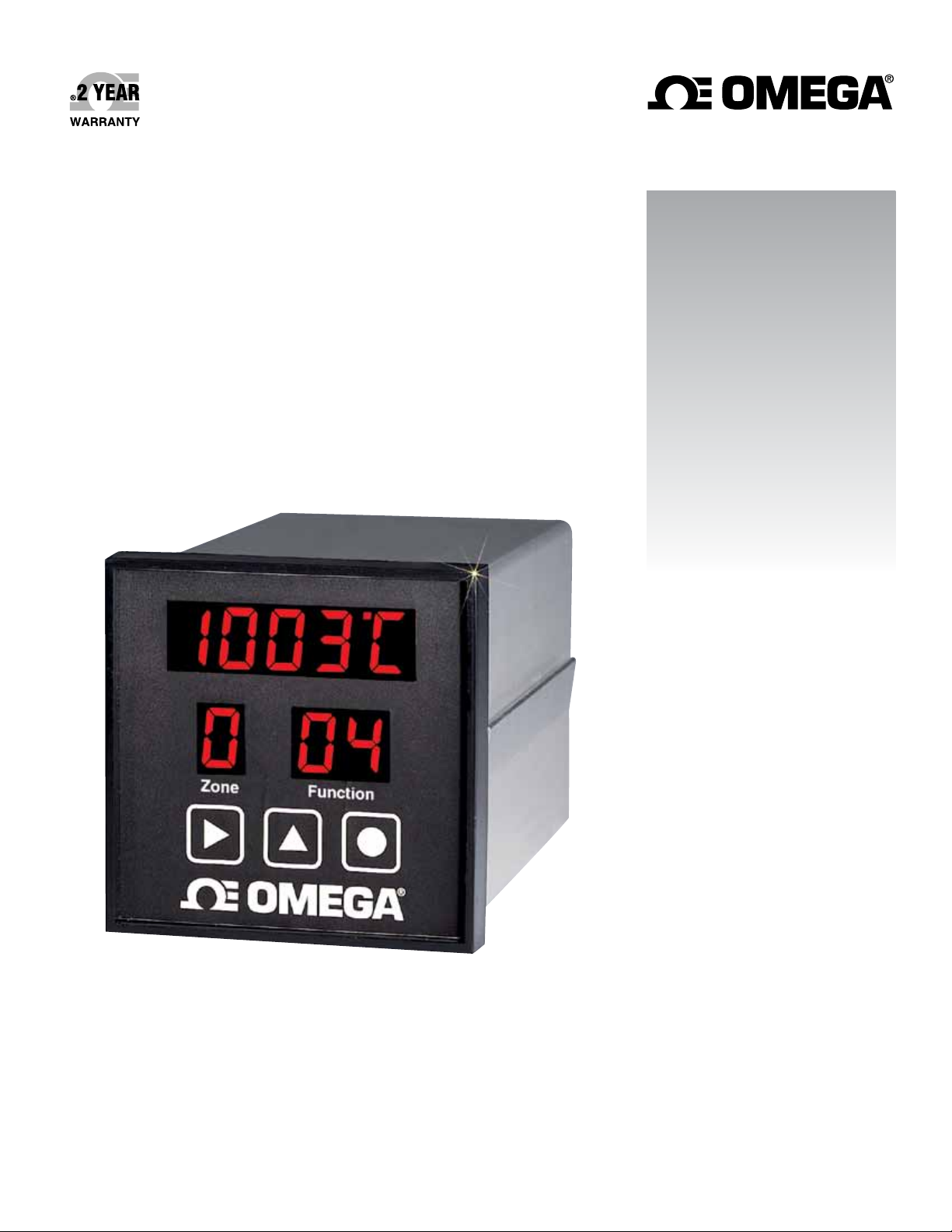
CN616 SERIES
1
⁄4 DIN Economical 6-Zone
PID Temperature Controllers
Page 2

omega.com [email protected]
Servicing North America:
U.S.A. Omega Engineering, Inc.
Headquarters: Toll-Free: 1-800-826-6342 (USA & Canada only)
Customer Service: 1-800-622-2378 (USA & Canada only)
Engineering Service: 1-800-872-9436 (USA & Canada only)
Tel: (203) 359-1660 Fax: (203) 359-7700
e-mail: [email protected]
For Other Locations Visit omega.com/worldwide
The information contained in this document is believed to be correct, but OMEGA accepts no liability for any errors it contains, and reserves
the right to alter specifications without notice.
Page 3

Table of Contents
SECTION PAGE
SECTION 1 INTRODUCTION . . . . . . . . . . . . . . . . . . .
1.1 Description . . . . . . . . . . . . . . . . . . . . . . . . . . . . . .
1.2 Features . . . . . . . . . . . . . . . . . . . . . . . . . . . . . . . .
1.3 Models . . . . . . . . . . . . . . . . . . . . . . . . . . . . . . . . .
1.4 Overview of operation
SECTION 2 RS-232 COMMUNICATIONS . . . . . . . . .
2.1 Description . . . . . . . . . . . . . . . . . . . . . . . . . . . . . .
2.2 RS-232 Cable Connections . . . . . . . . . . . . . . . . . .
2.3 Operating Protocol . . . . . . . . . . . . . . . . . . . . . . . .
2.4 RS-232 PC Screens . . . . . . . . . . . . . . . . . . . . . . . .
SECTION 3 INSTALLATION . . . . . . . . . . . . . . . . . . . .
3.1 Unpacking . . . . . . . . . . . . . . . . . . . . . . . . . . . . . .
3.2 Mounting . . . . . . . . . . . . . . . . . . . . . . . . . . . . . . .
3.3 Outline Dimensions . . . . . . . . . . . . . . . . . . . . . . .
3.4 Wiring the Power Circuit . . . . . . . . . . . . . . . . . . . .
3.5 Changing Line Voltage Setting . . . . . . . . . . . . . . .
3.6 Sensor Placement . . . . . . . . . . . . . . . . . . . . . . . . .
SECTION 4 PARTS OF THE CONTROLLER . . . . . . .
4.1 Front of the Controller . . . . . . . . . . . . . . . . . . . . . . .
4.2 Button Functions . . . . . . . . . . . . . . . . . . . . . . . . . .
4.3 Back of the Controller . . . . . . . . . . . . . . . . . . . . . . .
4.4 Temperature/Setpoint Display . . . . . . . . . . . . . . .
SECTION 5 “RUN MODE” . . . . . . . . . . . . . . . . . . . . . .
5.1 PID Control Mode . . . . . . . . . . . . . . . . . . . . . . . .
5.2 RAMP and SOAK CONTROL 1 . . . . . . . . . . . . .
5.3 RAMP and SOAK CONTROL 2 . . . . . . . . . . . . .
SECTION 6 SETUP AND OPERATION. . . . . . . . . . . . . . .
6.1 Summary . . . . . . . . . . . . . . . . . . . . . . . . . . . . . . . .
6.2 Security . . . . . . . . . . . . . . . . . . . . . . . . . . . . . . . .
6.3 Setup Control . . . . . . . . . . . . . . . . . . . . . . . . . . . .
6.4 Model Setup . . . . . . . . . . . . . . . . . . . . . . . . . . . .
6.5 Setpoints and Alarms . . . . . . . . . . . . . . . . . . . . . .
6.6 PID setting . . . . . . . . . . . . . . . . . . . . . . . . . . . . . .
6.7 Segment control . . . . . . . . . . . . . . . . . . . . . . . . . .
6.8 Ramp and Soak . . . . . . . . . . . . . . . . . . . . . . . . . .
6.9 Set Autotune . . . . . . . . . . . . . . . . . . . . . . . . . . . . .
6.10 Run Autotune . . . . . . . . . . . . . . . . . . . . . . . . . . .
6.11 Calibration . . . . . . . . . . . . . . . . . . . . . . . . . . . . .
6.12 Start Profile . . . . . . . . . . . . . . . . . . . . . . . . . . . .
7.1 Thermocouple Ranges . . . . . . . . . . . . . . . . . . . . . . .
SECTION 8 SPECIFICATIONS . . . . . . . . . . . . . . .
. . . . . . . . . . . . . . . . . .
2
2
2
3
3
7
7
7
8
12
15
15
15
16
16
17
17
18
18
19
20
21
22
22
22
22
23
24
26
26
26
29
31
33
34
35
35
36
37
38
39
SECTION 1 INTRODUCTION
1.1 Description
The CN616 Series is a second generation of industrial temperature
controllers based on the field proven CN100 six zone temperature
monitor/alarm system. Two models are available, standard and extended range.
The CN616 Series is a microprocessor based temperature controller,
which accepts signals from thermocouples. Six zones are sequentially
scanned at 15 readings per second [@ 60 Hz] and displayed with a
selectable display rate of 1 to 40 seconds each zone. A single output
relay is provided to indicate an alarm condition on any one zone. Six
PID time proportional or on/off outputs are provided to control six
zones. The faceplate has been arranged to call attention to an alarm
condition by flashing the main temperature display and indicating the
zone in alarm with a flashing zone number display. The CN616 Series
implements a security password to protect all functions.
1.2 Features
• Six Zones
• Selectable control mode [PID or On/Off] each zone
• Selectable cooling control mode [On/Off only] each zone
• 20 Segment Profile for each zone
• Selectable number of active zones
• Adjustable Display Time
• Field Proven Zone Switching
• Temperature and Setpoint Monitoring
• Four Digit Display of Temperature
• 1 Digit Display of Zones
• 5 Amp Latching or Non-Latching Relay
• Standard Thermocouples [T,E,J,K,S,R,B,C]
• Extended Ranges [ K and E thermocouple types ]
• Programmable Selection of HI, LO or HI/LO Alarms
• Password Protection
• 1/4 DIN Aluminum Box
• Splash Proof Face
• Plug-In I/O Terminals
• RS-232 Communication
2
Page 4

1.3 Models
Two Models are available:
CN616TC1 - Standard Range Thermocouple
CN616TC2 - Extended Range Thermocouple
1.4 Overview of operation
On power up the controller enters one of three run modes determined by
model configuration (function [71] 33)
Mode 1 [00] Standard Control
Mode 2 [51] Ramp & Soak 1 - end power off
Mode 3 [52] Ramp & Soak 2 - end run last setpoint
Each zone runs as an independent controller, except for PID parameters,
(proportional band, reset and rate) and output cycle time which are
common to all zones. In on/off mode hysteresis is common to all zones.
Any zone can be disabled or set to run under PID control or on/off
control (heating or cooling) independent of other zones. If all zones are
disabled, zone 1 will be enabled by default.
Each zone can be setup to run as a standard control, set independently
with function [36], or as a profile of up to 20 segments set by functions
[01] to [20].
To run a standard control, set the number of segments (function [74]) for
that zone to 0.
To run any zone in PID control mode set the PID zone enable function
[43]. To disable any zone use function [31].
Alarms
The CN616 has 4 alarm options set by model select function [33].
0. Overheat Alarm
1. Underheat Alarm
2. Hi - Lo Alarm
3. No Alarm
Overheat or Hi alarm is triggered by temperature going over the
setpoint beyond boundary set by the hi alarm setpoint. To trigger the
3
alarm the temperature must stay in alarm condition for a few
seconds. This is to prevent a false alarm.
Underheat or Lo alarm is disabled until enabled zone reach and stay
over the setpoint for a set time. This is to prevent alarm when starting
from cold. When Lo alarm is enabled it will be triggered only when
confirmed over time same as Hi alarm.
Hi - Lo works the same as Overheat and Underheat alarms.
No Alarm disables both Hi and Lo alarms.
When any zone goes into an alarm condition zone scan lock is disabled,
and when the alarm zone is displayed the temperature display will flash.
Hi alarm is indicated by flashing left function digit while Lo alarm is
indicated by flashing right function digit. In case of latching alarm, Hi
alarm takes precedence and Hi alarm will show even if both alarms are
latched.
Note! Whenever the “Run” Mode is exited to set or power off all
alarms are reset.
Autotune
The PID control constants that are the same for all zones programmed
for PID Mode. Autotuning can be done on any one zone selected for
the Autotuning. The system parameters are measured during autotuning
by supplying full power output to the system until the autotuning setpoint
is reached, then the output power is switched Off allowing the temperature to overshoot and then drop down freely back to the autotuning
setpoint. Then the power is switched on again until setpoint is crossed.
At that point autotuning is completed, the PID constants are calculated
and stored in memory until the next autotuning or manual changes are
made. For best results the autotuning setpoint should be as close as
possible to the control setpoint. However, since the temperature will
overshoot the autotuning setpoint during the autotune by the full proportional band, Systems that cannot tolerate that temperature should have
autotuning setpoint one proportional band value below the control
setpoint.
Setting of the controller can be entered from run mode, by pressing two
buttons together, that will request password, function [99], unless
password is disabled, then controller will go into function [70], which is
the function select.
4
Page 5
PID
All zones set for PID use the same PID parameters i.e.:- Proportional
band, Reset and Rate. These are derived from autotuning or manual
setting. T o achieve closest control the slowest zone should be chosen
for the autotuning. If control is not optimal manual adjustment may be
advisable.
On Off
On-off control is available for zones not set for PID control. All zones
under on-off control are subject to the same hysteresis setting.
Profiling
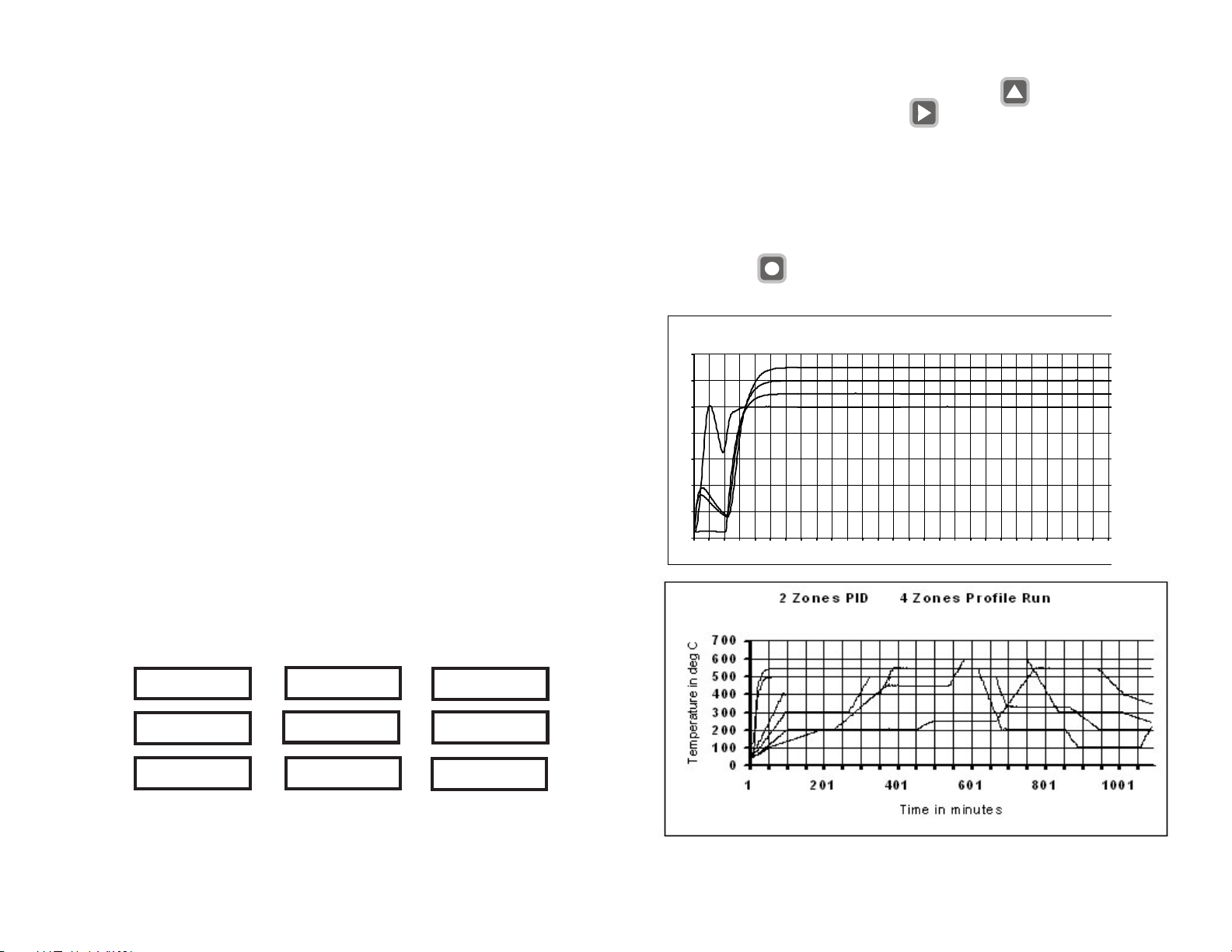
The CN616 allows the process to be controlled under a precise time/
temperature profile.
The Profile of each zone can be set within 20 segments.
Each segment consists of 3 parameters
1. Setpoint in °C or °F
2. Slope in °C / min. or °F / min.
3. Time in hours
Note ! Slope always takes precedence over the time. That means that
if slope is set then time will be ignored. To activate time slope must be
set to (0). When slope is set to (0) time is used to calculate the slope for
ramp. This way finer slope setting is possible.
Warning! In Soak application slope must be set to (0), otherwise time
will be ignored and soak will not occur.
T o start setting a Profile, the main display shows the setpoint with
the first digit (MS) flashing. Set digits with the button. Then
scroll through the display with the button. After scrolling
through 4 digits the display will change to slope. The slope has only
3 digits, after scrolling through slope main display will show 4 digit
time, and after time setpoint again. T o distinguish between setpoint
slope and time setpoint has 4 full digits, slope has 3 digits with
decimal point after second digit, and time has 4 digits with a
decimal point after second digit. When all parameters are set save
data with the
button. Saving data will advance display to the next segment.
Autotu ne zon e1 Run zone s 1, 2, 3 & 4
700
600
500
400
300
200
100
0
1 301 601
Example of setting Profile Segments
Segment 2
0 2 0 0
0 0.0
0 1. 0 0
Soak at 200 deg for
1 hour
Setpoint
Slope
Time
Segment 1
0 2 0 0
0 4.0
0 0. 0 0
Starting from the current
temperature go to 200
deg at 4 deg /minute
5
Segment 3
0 4 0 0
0 8.0
0 0. 0 0
Climb to 400 deg at
a rate of 8 deg per
minute
6
Page 6
SECTION 2
RS-232 COMMUNICATIONS
NOTE: Minimum requirements to run RS-232 software is
a PC computer with Windows 95.
2.1 Description
2.3 Operating Protocol for RS-232 Communications
The CN616 Controller is designed with standard RS-232 three wire serial
communication capabilities. Up to ten controllers can be parallel connected to a single PC. The transmission line is held in tristate to avoid
cross-talk between controllers except when the computer addresses a
specific controller for communication.
Up to ten controllers can be connected in parallel to a single
RS-232 communications port on a PC. Each controller is assigned a
serial number from 0 to 9 known as the RS-232 ID code. The computer uses these numbers to determine which controller unit to address
at a given time. Each controller must have a different ID.
A simple set of menus is provided in the software which allows the
operator to change the settings of each connected controller unit and
display individual operating parameters.
For users with advanced software capabilities, see Section 2.4 for an
operating protocol.
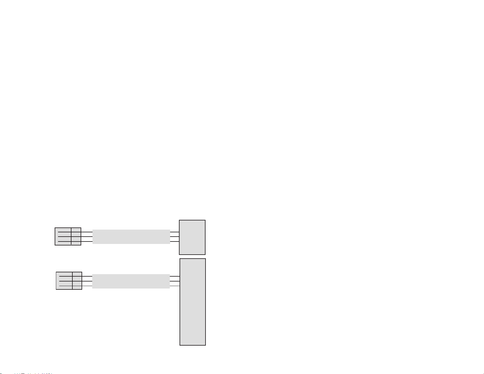
2.2 RS-232 Cable Connections
9 PIN
COMPORT
C
IN
OUT
CONTROLLER
PLUG
C
IN
OUT
CONTROLLER
PLUG
3 WIRE CABLE
25 PIN
COMPORT
3 WIRE CABLE
5
3
2
7
2
3
Configuration
BAUD rate = 4800
Data bits = 8
Parity = N
Stop = 1
Communication software for the PC is written in Visual Basic. This
software package has been created to operate on PC Windows 95
platform meeting the minimum requirements.
Customers can communicate with CN616 controllers through a PC by
using the following protocol:
• Controllers will not initiate communication. The RS-232
Command Module (computer or similar device) must initiate.
• All communication is in ASCII format
• To start communication, the Command Module must send alert
code ASCII [L] hex 4C. This commands the controllers to cease RS232 communication and listen for an RS-232 ID Code. The Command
Module then sends the Identification Number for the controller that it
needs to address, ASCII [0 to 9] hex 30 to 39. The identified controller
will then expect a command code. All the other controllers on-line will
wait for the next alert code.
• Command codes are divided into two groups:
Group 1. Commands “ CAPITAL” requesting data from the
controller.
Group 2. Commands “ small” sending data to the controller.
7
8
Page 7

2.3.1 List of data transfer Codes
Parameters:- Code “J” controller sends string
Code “j” controller receive string
Protocol from computer “ L3J” request for data
“ L3j” + string of data
Data string 16 characters long
zone enable [77]
password enable [x0]
model [1204]
ID [x9]
scan time [39]
password [1011]
zone enable code [ 0111 0111 ] binary
654 321 zones
Setpoints:- Code “B” controller sends string
Code “b” controller receive string
Protocol from computer “ L3B” request for data
“ L3b” + string of data
Data string 24 characters long [6 setpoints 4 characters each.]
High alarms:- Code “C” controller sends string
Code “c” controller receive string
Protocol from computer “ L3C” request for data
“ L3c” + string of data
Data string 24 characters long [6 high alarms 4 characters each.]
Low alarms:- Code “D” controller sends string
Code “d” controller receive string
Protocol from computer “ L3D” request for data
“ L3d” + string of data
Data string 24 characters long [6 low alarms 4 characters each.]
Number of segments:- Code “F” controller sends string
Code “f” controller receive string
Protocol from computer “ L3F” request for data
“ L3f” + string of data
Data string 12 characters long. [6 zones 2 characters each](00 to 20)
Segment parameters:- Code “U” controller sends string
Code “u” controller receive string
Protocol from computer “ L3U”request for data for zone 1
“ L3u” + string of data for zone 1
Data string 240 characters long. Segment data zone 1
20 segments 12 characters each segment
[9999] setpoint 9999 degrees
[0999] slope 99.9 degrees/minute
[9999] time 99.99 hours
Segments:- Codes “V” to “Z” same format as code “U”
Code “V” zone 2
Code “W” zone 3
Code “X” zone 4
Code “Y” zone 5
Code “Z” zone 6
Temperature and alarms:- Code “T” controller sends string
Protocol from computer “ L3T” request for data
Data string 28 characters long. temperature of 6 zones and alarms
[9999] temperature zones 1, 2, 3, 4, 5, & 6
[77] high alarm
[77] low alarm
Start Profile:- Code “p” controller receive string
Protocol from computer “ L3p” + string of data
Data string 2 characters long. [zF]
z = (0 to 6) = zone to profile, (7) = all zones F = filler
Current setpoints:- Code “R” controller sends string
Protocol from computer “ L3R” request for data
Data string 24 characters long. Setpoints of 6 zones
[9999] Setpoint zones 1, 2, 3, 4, 5, & 6 (updated by profile)
9
10
Page 8
PID parameters:- Code “K” controller sends string
Code “k” controller receive string
Protocol from computer “ L3K” request for data
“ L3k” + string of data
Data string 22 characters long
[9990] cycle time 99.90 seconds
[99] hystereses 99 degrees
[77] PID zone enable 0111 0111
[9999] proportional band 9999 degrees
[0999] reset 9.99
[9999] rate 99.99
[77] Cooling zone enable 0111 0111
Set for Autotune:- Code “S” controller sends string
Code “s” controller receive string
Protocol from computer “ L3S” request for data (8 ch)
“ L3s” + string of data (6 ch)
Data string send 8 characters long ; receive 6 characters long
[06] zone for Autotune [1 to 6]
[9999] autotune setpoint
[61] run mode [00, 51, 52, 61, .... “S” send only ]
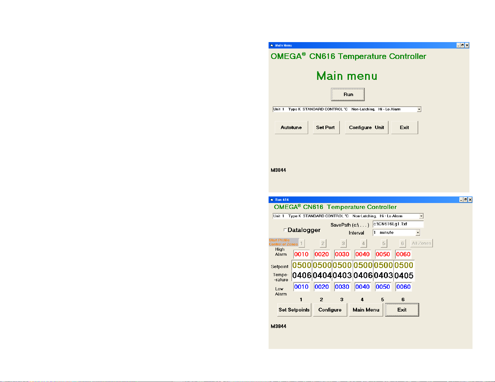
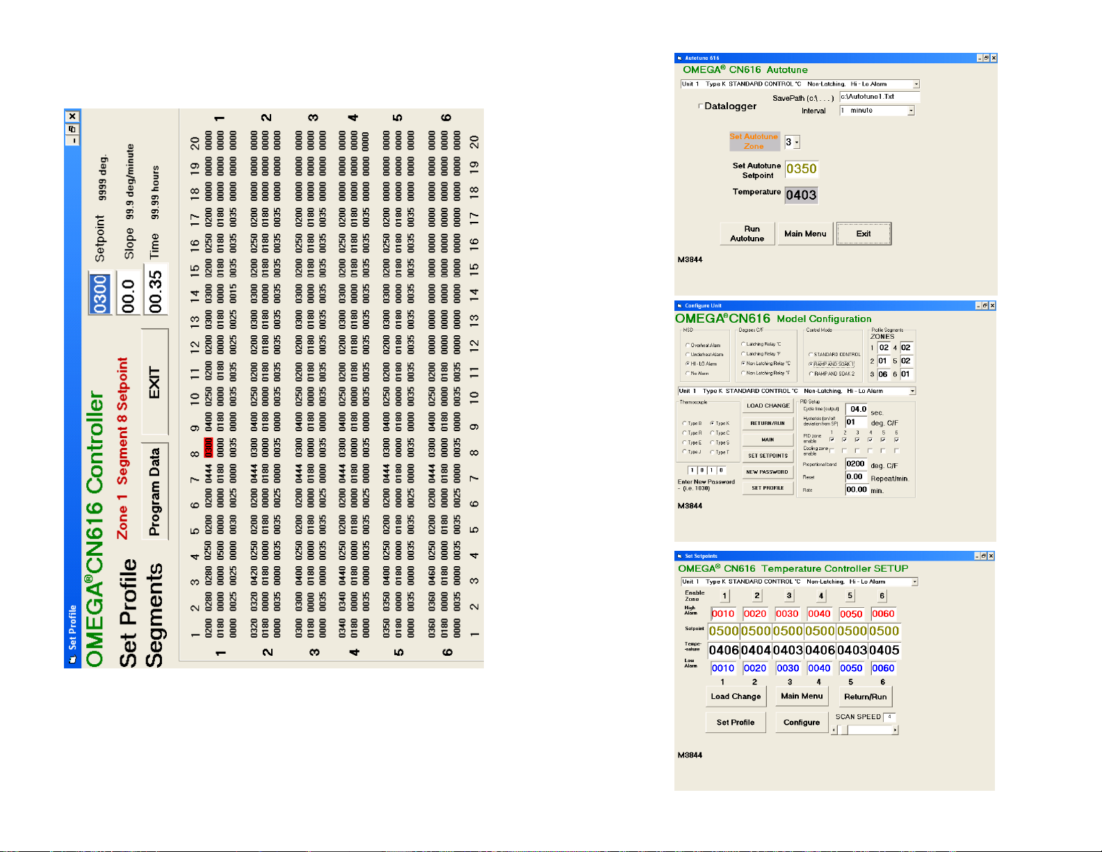
2.4 RS-232 PC Screens
Six examples of program screens are shown below.
Start Autotune:- Code “G” controller receive command
Protocol from computer “ L3G” Start command
Stop Autotune:- Code “H” controller receive command
Protocol from computer “ L3H” Stop command
Notes:-
1. All data sent to the controller must be decimal (ASCII format).
2. All data sent to the controller and code “G & H” are echoed
back to the computer.
3. Any non decimal character in the data stream will terminate
reception, and data received to that point will be ignored.
11
12 To enable Data Logging click on the Datalogger box.
Page 9
13
14
Page 10
SECTION 3
INSTALLATION
3.1 Unpacking
Upon receipt of shipment, inspect the container and equipment for any
signs of damage. Take particular note of any evidence of rough handling
in transit. Immediately report any damage to the shipping agent.
Remove the packing list and verify that all equipment has been received.
Each package should contain:
• Controller (CN616)
• Operator's Manual
• RS-232 Software
• Two mounting slides with screws
• Power plug (9 pin)
• RS-232 plug (3 pin)
• Two T/C plugs (6 pin)
• Two Output plugs (6 pin)
If there are any questions about the shipment, please call the Customer
Service Department.
NOTE: The carrier will not honor any claims unless all shipping material
is saved for their examination. After examining and removing contents,
save packing material and carton in the event reshipment is necessary.
3.2 Mounting
Select a location for the controller that is free from excessive shock,
vibration, dirt, moisture and oil. Mount the controller into a 3 5/8"
(92mm) square cutout. The controller as shipped is 1/4 DIN (92mm
square), so it does not have to be removed from it's housing to be
mounted.
Remove the two screws that secure the mounting slides. Remove the
slides and insert the case into the cutout from the front side of the panel.
Reinstall the two slides and two screws. The length of the slides must be
reduced if the controller is to be mounted in an extra thick panel.
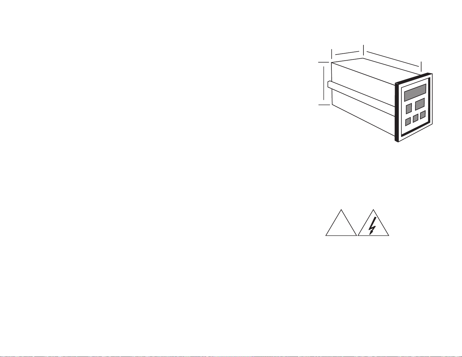
3.3 Outline Dimensions
3.62"
(92mm)
6.0" (152mm)
3.62"
(92mm)
3.4 Wiring the Power Circuit
The line voltage for the controller is selected by an external jumper
assembly to operate either on 120VAC or 240VAC±10%, 50/60Hz
(factory wired for 120VAC). It is very important that the proper line
voltage is connected to the instrument. If 120VAC is connected to a
240VAC model, it will not work properly. A 120VAC instrument
connected to 240VAC will overheat and burn the input transformer.
WARNING! !
!
The controller is powered with either 120
or 240 VAC. To avoid electric shock or
fatality hazards the power to the controller
lines must be switched off at the main
switch, or circuit breaker before the
controller A/C wiring, including the line
selector jumpers can be handled.
15
16
Page 11
3.5 Changing Line Voltage Setting
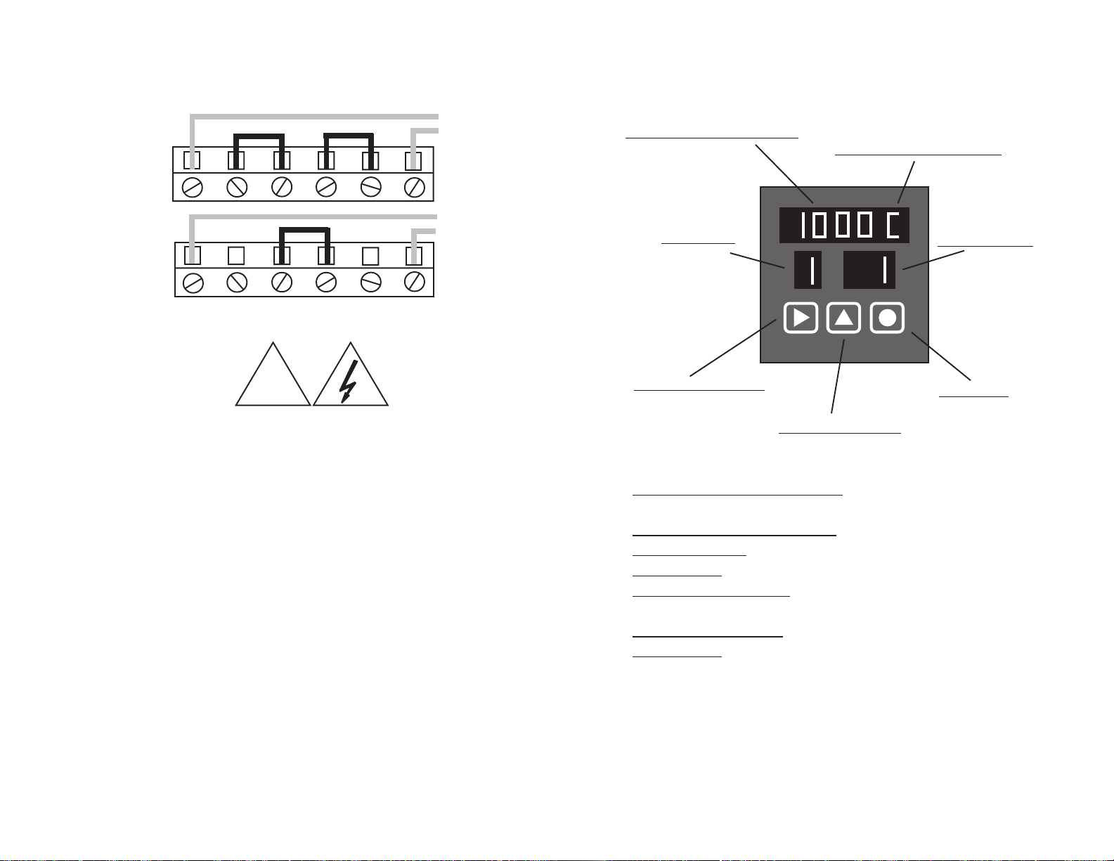
Program the input line voltage by placing jumpers on the line plug as
shown:
LINE
120VAC
120V Jumper
Placement:
SECTION 4
PARTS OF THE INSTRUMENT
Temperature\Setpoint Display
Temperature Scale Selection
LINE
240VAC
240V Jumper
Placement:
WARNING! !
Line Voltage
see Pg 16
3.6 Sensor Placement
Proper sensor placement is essential. It can eliminate many problems in
the total system. The probe should be placed so that it can detect any
temperature change with little thermal lag. In a process that requires
fairly constant heat output, the probe should be placed close to the
heater. In processes where the heat demand is variable, the probe
should be close to the work area. Experimenting with probe location
can often provide optimum results. Some units are shock sensitive and
require care in handling and installation. To avoid current feedback from
zone to zone and from zone to RS-232 communications, ungrounded
thermocouples are recommended. Thermocouple wires should not be
placed in the same conduit as the power lines.
!
º
Zone Setting
Set\Shift\Reset Button
Zone
Advance Digit Button
Function
Function Setting
Load Button
Temperature\Setpoint Display- Main display with multiple
functions.
Temperature Scale Selection- Choice of °C or °F.
Function Setting- Indicates the operating status of the instrument.
Zone Setting- Indicates an active zone or a zone that is being set.
Set\Shift\Reset Button- Used to select digits during setup or to
unlock the display scan.
Advance Digit Button- Used to increment selected digit.
Load Button- Used to accept a setting or to lock display zone.
17
18
Page 12
4.2 Button Functions
There are three flatpad buttons provided and two combinations of
buttons for separate functions.
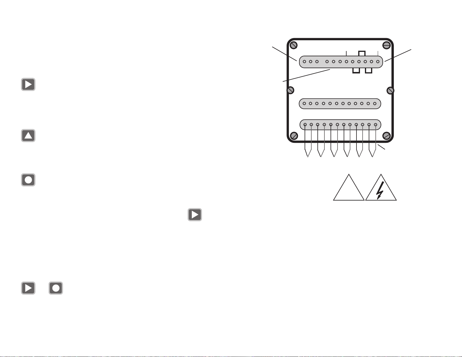
4.3 Back of the Controller
RS-232
Port
RS-232
C IN OUT NC NO C
RELAY
LINE VOLTAGE
240V
LV
Line Voltage
LV
and Jumpers
Shift Button
1. Selects Digit
2. Unlock Zones scan
3. Switches Main Display Functions
Advance Digit Button
1. Advances flashing Digits
2. Advances Zones
Load Button
1. Lock zone scan during “RUN MODE”
Note! Zone scan is unlocked by the shift button,
or by an alarm condition. In alarm state zone scan can not be locked.
2. Load set parameters into the memory
in “SET MODE”
Shift Button & Load Button (together)
&
SPDT
Relay
Connect
OUTPUT
DC Z1 Z2 Z3 Z4 C C Z5 Z5 Z6 Z6 DC
INPUT
Z1 Z2 Z3 Z4 Z5 Z6
120V
+ -
• • • • • •
THERMOCOUPLES
WARNING! !
Line Voltage
see Pg 16
RS-232 Port- Cable connection (see Section 1.3)
C - Common Pin 5
IN - Input Pin 3
OUT - Output Pin 2
Relay
NC- Non-energized Closed
NO- Non-energized Open
C- Common
}
!
9 Pin Comport
Red Wire
19
1. Enter "FUNCTION SELECT" MODE
2. Exits "FUNCTION SELECT" MODE
3. Resets Alarm during "RUN MODE”
Line
LV- 120VAC or 240VAC cable
Jumpers- Determines voltage input (see Section 3.4)
20
Page 13
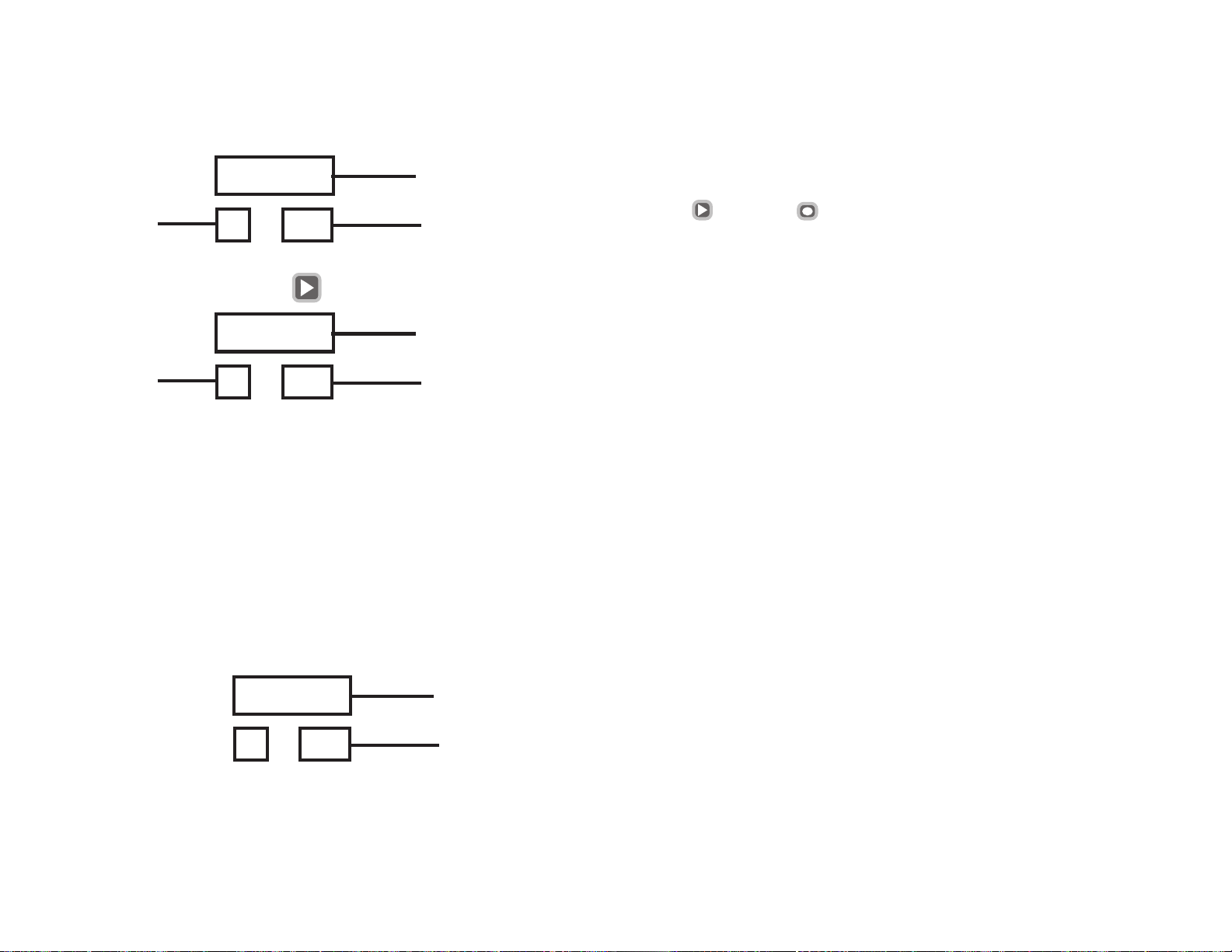
4.4 Temperature/Setpoint Display (Main Display)
During "RUN" MODE, the Main Display is used to monitor zone
temperatures, check setpoints, and indicate ALARM conditions.
0 5 2 2
Zone
By pressing and holding button The display will change to
5 13
0 5 2 0
Zone
Flashing
During operator programming in "FUNCTION SELECT"
MODE, the Main Display is used to:
1. Set the Zone Setpoints
2. Enter Passwords
3. Select Functions
4. Set the Zone Display Time
5. Select the Instrument Model
6. Select Run parameters
During CALIBRATION (Function 78), the Main Display is used
to:
5 13
3 1.0 5
7 8
1. Set calibration millivolts
21
Temperature
Run Mode
Setpoint
Run Mode
Mv
Function
SECTION 5
“RUN” MODE
In the “RUN” Mode, the CN616 controls the temperature under the
program established during the last “SET” Mode. The “RUN” Mode is
entered every time the controller is powered, after a power interruption, or
it can be entered manually from the “SET” Mode, by pushing buttons
and together
“SET” Mode TIME OUT. If the instrument is left unattended for over 2
minutes in the “SET” Mode, the program will switch it back to “RUN”
Mode.
Three “RUN” Modes are available
1. [00] Standard Control FN 33 Control Mode (digit 3) = 0
2. [51] RAMP & SOAK 1 FN 33 Control Mode (digit 3) = 1
3. [52] RAMP & SOAK 2 FN 33 Control Mode (digit 3) = 2
5.1 PID CONTROL MODE
Each one of the six zones is treated as a separate controller and it can run
under any one of the following Modes
1. PID enable FN 43
2. Proportional Band (PB) FN 44 - FN 45 & 46 set to 0
3. Proportional Band and Reset (PI) FN 44 & 45 - FN 46 set to 0
4. Proportional Band and Rate (PD) FN 44 & 46 - FN 45 set to 0
5. Proportional Band Reset and Rate (PID) FN 44 , 45 & 46
6. Disabled (OFF) FN 31
NOTE!! The PID setting is common to all zones i.e.:it can not be changed from zone to zone.
The zones can be mixed and set to either PID or ON-OFF FN [43]
5.2 RAMP & SOAK CONTROL 1
In this Mode each zone will follow the RAMP & SOAK program set in
Section 6: FN 74 & 75 . At the end of the Profile “RUN” the output power
will be switched OFF.
5.3 RAMP AND SOAK CONTROL 2
This Mode is exactly the same as RAMP & SOAK 1 except that at the end
of the Profile “RUN” the controller will control the temperature at the setpoint
of the last segment indefinitely.
22
Page 14
NOTE !!
To run Ramp & Soak
Unit must be set to run mode 51 or 52. [Fn 33]
Number of segments must be more than 0 [Fn 74]
Any zone set to # segments = 0 will run in STANDARD mode.
Until PROFILE is started [Fn 79] zone will run in STANDARD mode.
Function 79 will start Profile for any single zone or all zones at once.
First segment will start control from ambient temperature setpoint and
take it to the first segment setpoint at the set rate.
At any time PROFILE can be started again, it will go to the start of the first
segment
SECTION 6 SETUP AND OPERATION
This section deals with setting up all of the parameters of the CN616
Temperature Controller. FN [70] is assigned for that task. The setup
operation is protected by a security password to prevent accidental or
unauthorized modifications.
On power up the CN616 controller will enter “RUN” Mode. To enter
setup mode press buttons and together for few seconds
until function [99] or [70] is displayed in the function display.
If password protection is enabled function [99] will request a password.
Entry of a four digit password is required to enter function select mode
FN [70].
The password is set at the factory to “1011”. The password can only be
changed by the software or at the factory.
To enter the password use the button to increment each digit,
use the button to move to the next digit and the button to
enter the password. Entering a wrong password will return the controller
to the “RUN” Mode.
NOTE!!
To avoid inadvertent changes to control settings access to every function
must be confirmed by reentering function number.
6.1 Summary
Controller setting is organized in 8 major functions and function groups
[71 to 78] and their related functions, listed below .
Funct ion 7 1 Model Setup Group
function 31 zone enable
function 32 password enable
function 33 model select
function 34 ID for RS-232
function 35 zone display time
Function 72 Control Setup Group
function 36 setpoint
function 37 high alarm (over setpoint)
function 38 low alarm (under setpoint)
Function 73 PID Setup Group
function 41 cycle time (output)
function 42 hystereses (on/off deviation from SP)
function 43 set PID zone
function 44 proportional band
function 45 reset
function 46 rate
function 47 set COOLING zone
Func tio n 74 number of segments for each zone
Function 75 set segments
function 01 segment 01 zone 1 to 6
to function 20 segment 20 zone 1 to 6
Func tio n 76 set setpoint and zone for autotune
Function 77 autotune
function 61 autotune stage 1
function 62 autotune stage 2
function 63 autotune stage 3
Function 78 calibrate
23
Function 79 Start Profile
24
Page 15
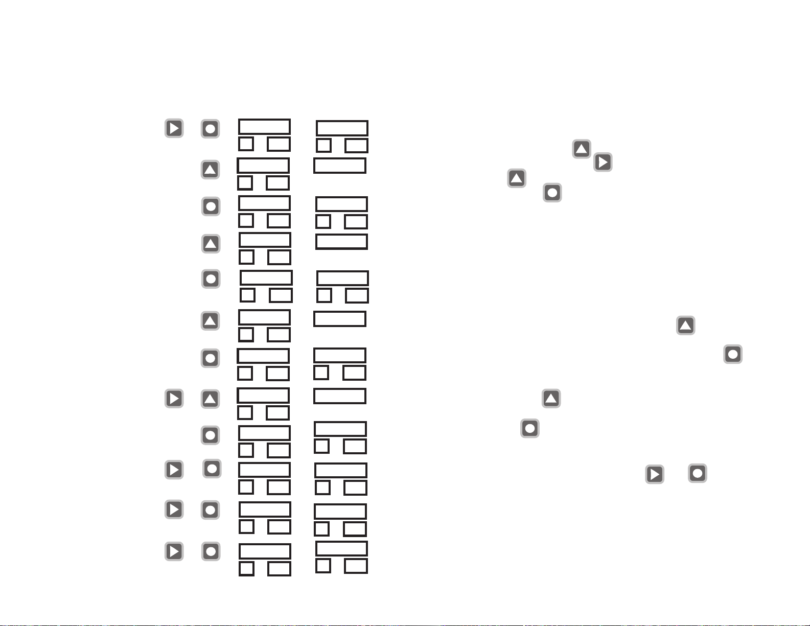
EXAMPLE: Set High Alarm Setpoint [over setpoint]
Action
Enter Setup mode
Select Function Group
Enter Function Group
Confirm Selection
Buttons to use
together
Display Before Display After
0 4 0 3
7 0
0 01
7 1
7 0
7 2
7 0
7 2
=>
=>
=>
=>
7 0
7 2
7 1
7 0
7 2
7 2
6.2 Function [99] Security
Security password protects all setup functions from accidental or
unauthorized modifications. The security password is factory preset
At 1011 and it can be changed only under RS232 computer program. The security can be enabled or disabled within Function [71]
Model Setup. Whenever FN [99] appears, in function window, it
means that the security is enabled and password must be entered one
digit at a time. Using button enter the correct number in the
flashing digit, then using button shift to the next digit and again
using button enter the correct number. Repeat for all four
digits, then enter with button . If password is correct the FN
[70] will appear in function window. If not correct the controller will
return to the “RUN” Mode. If the process times out the display will
return “RUN” Mode.
6. 3 Function [70] Function Set up Control
Enter
Select SubFunction
Enter
[repeat for each zone]
Set Values
Enter and go to next
Zone
EXIT setpoints
EXIT SubFunction
EXIT Function
25
one button at a time
together
together
together
7 2
7 2
3 6
7 2
3 7
7 2
0 0 0 0
3 71
0 0 1 5
3 71
0 0 2 0
3 72
3 6
7 2
7 1
7 0
=>
=>
=>
=>
=>
=>
=>
=>
3 6
3 7
0 0 0 0
3 71
0 0 1 5
0 0 2 0
3 72
3 6
7 2
7 1
7 0
0 4 0 3
0 01
Function [70] is entered from function [99] or directly from
“RUN” Mode if password security is disabled.
In function [70] , the number 70 is displayed in the function window, Increment the flashing digit with the button until
required function shows in the upper display, function [71] to
function [78] then enter the selected function with the button
that will display entered function in function window and 70 in the
top display. To confirm the function selection increment the flashing
digit with the button until the upper display matches the
function display. At this point enter confirmation of the selection
with the button If the process times out the display will
return “RUN” Mode. If the two displays do not match, the con-
troller will return to function [70].
To return to RUN mode press two buttons and together
for a few seconds.
6. 4 Function Group [71] Model Setup
Function [71] controls functions [31] to [35]
On entering function [71] the function display shows 71. The upper
display shows 31. To select functions
26
Page 16
[32]-[35] increment the flashing digit with the button When the
desired function is displayed enter it with the button This will
display the desired function in the function display.
If the process times out the display will return “RUN” Mode.
To return to function [70] press two buttons and together
for a few seconds.
6.4.1 Function [31] zone enable
The zone enable function is used to enable/disable any or all of the
zones individually. If all of the zones are disabled then zone one will
remain enabled by default
In function [31] the function display will show 31, the zone display will
show 1, and the upper display will be blank.
If the zone display is flashing it indicates that the current zone is disabled.
To toggle between enable and disable use the button
To advance to next zone use the button
To save the settings and return to function [71] use the button
To increment the flashing digit use the button
To advance to the next digit use the button
To save the settings and return to function [71] use the button
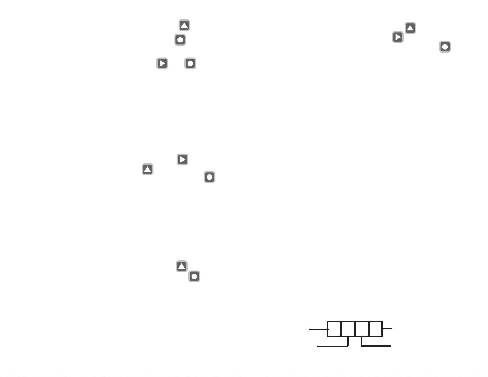
Four digit model code
Digit 1 0 = Overheat Alarm
A la r m 1 = Underheat Alarm
Type 2 = HI-LO Alarm
3 = No Alarm
Digit 2 0 = Latching Rel. °C
Re l ay 1 = Latching Rel. °F
And °C or °F 2 = Non Latching °C
3 = Non Latching °F
Digit 3 0 = STANDARD CONTROL
CONTROL 1 = RAMP AND SOAK 1
MODE 2 = RAMP AND SOAK 2
6.4.2 Function [32] password enable
The password enable function turns on/off the password protection for
changing the settings for the unit. In function [32] the function display
will show 32, the zone display will be blank, and the upper display will
flash 0 or 1.
If the display is 0 it indicates that the password is disabled.
If the display is 1 it indicates that the password is enabled.
To toggle between enable and disable use the button
To save setting and return to function [71] use the button
6.4.3 Function [33] select model
The select model function sets the type of unit for alarms, relay, degrees
C or F, control mode, and thermocouple as per the table. In function
[33] the function display will show 33, the zone display will be blank,
and the upper display will show a 4 digit model code, digit 1 will be
flashing.
27
Digit 4 0 = TYPE B
T/C TYPE 1 = TYPE C
2 = TYPE E
3 = TYPE J
4 = TYPE K
5 = TYPE R
6 = TYPE S
7 = TYPE T
Example:
T o select “RAMP AND SOAK 1” W ith type ‘K’ thermocouple °F
with Non Latching HI-LO Alarm, set MODEL as shown below .
HI-LO Alarm
Non Latching °F
28
2
3
1
4
TYPE K
RAMP AND SOAK 1
Page 17
6.4.4 Function [34] ID for RS232
The ID code for the RS-232 is the identifying number for each unit
connected through an RS-232 line to a computer. If two or more
units are connected to a computer every unit must be set to have a
different RS-232 ID code for proper operation. In function [34] the
function display will show 34, the zone display will be blank, and the
upper display will display the 1 digit RS-232 ID code. T o increment
the flashing digit use the button
T o save the settings and return to function [71] use the button
6.4.5 Function [35] zone display time
The zone display time function sets the time period that each temperature will display in the temperature window. The zone display is
settable to 1-40 seconds.
In function [35] the function display will show 35, the zone display will
be blank, and the upper display will show the two digit zone display
time.
To increment the flashing digit use the button
To advance to the next digit use the button
To save the settings and exit to function [71] use the button
In function [36] the function display will show 36, the zone display will
show 1, and the upper display will show the current setpoint.
To increment the flashing digit of the setpoint use the button
To advance to the next digit use the button
To save the settings and go to the next zone use the button
To exit to function [72] use the buttons and together for
a few seconds.
6.5.2 Function [37] high alarm (over setpoint)
The high alarm function sets the high temperature safety point for each
zone above which each zone will go into alarm mode.
In function [37] the function display will show 37, the zone display will
show 1, and the upper display will show the two digit current alarm
setting.
To increment the flashing digit of the setpoint use the button
To advance to the next digit use the button
To save the setting and go to the next zone use the button
To exit to function [72] use the buttons and together for a
few seconds.
6. 5 Function Group [72] Setpoints and Alarms
Function [72] controls functions [36] to [38]
On entering function [72] the function display shows 72. The upper
display reads 36. To select functions [36] to [38] increment the flashing
digit with the button When the desired function is displayed enter
it with the button This will display set function in function
display.
If the process times out the display will return “RUN” Mode.
To return to function [70] press two buttons and together
for a few seconds.
6.5.1 Function [36] setpoint
The setpoint function allows setting the control point of the temperature
controller for each zone. This setpoint is for STANDARD CONTROL
only. Ramp and Soak setpoints are set in function 75, or computer.
29
6.5.3 Function [38] low alarm (under setpoint)
The low alarm function sets the low temperature safety point for each
zone below which each zone will go into alarm mode. To prevent
alarming on low temperature during start-up the low alarm is disabled
until the zone exceed it’s setpoint for a set period of time.
In function [38] the function display will show 38, the zone display will
show 1, and the upper display will show the two digit current alarm.
To increment the flashing digit use the button
To advance to the next digit use the button
To save the setting and go to the next zone use the button
To exit to function [72] use the buttons and together for a
few seconds.
30
Page 18
6. 6 Function Group [73] PID Setup
6.6.3 Function [43] enable PID zone
The functions in group 73 allow the operator to examine and or change
the PID constants including those generated by autotuning. Function
[73] controls functions [41] to [46]
On entering function [73] function display shows 73. The upper display
shows 41. To select the desired function [41] to [46] increment the
flashing digit with the button When the desired
function is displayed enter it with the button This will display the
selected function in the function display.
If the process times out the display will return “RUN” Mode.
To return to function [70] press two buttons and together
for a few seconds.
6.6.1 Function [41] Output cycle time (99.9) sec...
This function allows the operator to examine and change the Output
cycle time
In function [41] the function display will show 41, the zone display will
be blank, and the upper display will show the three digit current Output
cycle time setting.
To increment the flashing digit press the button
To advance to the next digit press the button
To save setting and exit to function [73] press the button
The enable PID zone Function allows selection of on/off or PID control
for individual zones. In function [43] the function display will show 43,
the zone display will show 1, and the upper display will be blank.
If the zone display is flashing it indicates that the zone is selected for onoff control. If the zone display is not flashing then it is selected for PID
control.
To toggle between enable and disable use the button
To advance to the next zone use the button
To save the settings and return to function [73] use the button
6.6.4 Function [44] Proportional Band (9999) deg C or F
The proportional band function allows the user to examine and set the
proportional band.
In function [44] the function display will show 44, the zone display will
be blank, and the upper display will show the current Proportional
band.
To increment the flashing digit use the button
To advance to the next digit use the button
To save the settings and exit to function [73] use the button
6.6.5 Function [45] Reset (9.99) repeats / min.
6.6.2 Function [42] Hysteresis on-off control (99) deg C or F
In the on-off control with hysteresis function the operator can control
the dead band in which the output does not change. In function [42] the
function display will show 42, the zone display will be blank, and the
upper display will show the two digit current Hysteresis.
To increment the flashing digit press the button
To advance to the next digit press the button
To save setting and exit to function [73] press the button
31
The reset function allows the operator to examine and change the
integral function of PID control.
In function [45] the function display will show 45, the zone display will
be blank, and the upper display will show the three digit current Reset
setting.
To increment the flashing digit use the button
To advance to the next digit use the button
To exit to function [73] use the button
32
Page 19
6.6.6 Function [46] Rate (99.99) minutes
6. 8 Function Group [75] Ramp and Soak
The Rate function allows the operator to examine and change the
differential function of PID control.
In function [46] function display will show 46, the zone display will be
blank, and the upper display will show the current Rate.
To increment the flashing digit press the button
To advance to the next digit press the button
To save setting and exit to function [73] press the button
6.6.7 Function [47] enable Cooling zone
This function is set in the same manner as function [43].
Zones enabled by this function will run in on / off control mode and will
have outputs inverted to control cooling.
6.7 Function [74] Segment Control (set number
of Profile Segments for each zone)
The segments function allows the operator to set the size of the profile in
segments and the number of profile variants. Function [74] does not
control any other function
On entering function [74] function display shows 74.
Zone display shows zone 1.
The first and second digits in the upper display shows the current
number of segments for the displayed zone.
To increment the flashing digit press the button
To advance to the next digit press the button
To save the settings and go to the next zone press the button
To exit to function [70] use the buttons and together
for a few seconds.
Note !! The number of segments is restricted to 20 for each zone.
Setting 0 segments will force the controller to run that zone in a STANDARD Mode using setpoint set by function [36]. This allows a mix of
zones running STANDARD Mode and PROFILE
Function [75] controls segment functions [01] to [20]
On entering function [75] the function display shows 75. The upper
display will read 01 . The zone window will show 1.
To select the segment and zone to be set, enter the segment number and
zone. Note that the segment number is restricted by the number of
segments set in function [74].
To increment the flashing digit press the button
To advance to the next digit (segment and zone number) press the
button
To enter the segment to be set press the button
On entering segment display will advance to the next segment. If the last
segment of that zone is entered then display will advance to the first
segment of next zone.
To return to function [70] press two buttons and together
for a few seconds.
6.8.1 Function [01] Set Segment 1
Setpoint (99 99 ) de grees
Slope (99.9) deg / minute
Time (99.99) hours
In function [01] the function display will show 01.
The zone display will show the selected zone.
The upper display will show the 4 digit current Setpoint. To accommodate 3 parameters the upper display will scroll through 3 independent
displays. To recognize which display is shown each parameter has a
different look. The setpoint parameter displays 4 digits. The slope
parameter is displayed with three digits. The time parameter is displayed
with 2 digits followed by 2 decimal digits.
To increment the flashing digit press the button
To advance to the next digit and scroll press the button
To save the segment and advance to the next segment press the button
To return to function [75] press two buttons and together
for a few seconds.
33
34
Page 20
Note !! Only the number of segments set in function [74] are allowed to
be set. After last segment is saved the unit segment setup will advance to
the next zone. This way all segments are set in sequence. Out of sequence segments can be set by returning to function [75] after saving
each segment.
6.8.2-20 Function [02] to [20] Set Segment 02 to 20
follow the same procedure as Function [01]
Function [77] initiates unit autotuning.
On entering function [77] the function display reads 61.
The zone display shows the zone set for autotuning.
The upper display shows current temperature. When the top display
and function display are flashing the power is turned on.
When temperature reaches the Autotune setpoint the power goes off
and the function display shows 62. On completion of the autotuning the
controller returns to “RUN” Mode.
6.9 Function [76] Set Autotune
Function [76] does not control any other function
On entering function [76] the function display shows 76.
The zone display shows zone 1.
The upper display shows the current Autotune setpoint.
By advancing the flashing digit the operator can scroll through the top
display and the zone display and set the Autotune setpoint & zone.
To increment the flashing digit press the button
To advance to the next digit with press the button
To save the settings and return to function [70] press the button
6.10 Function [77] Run Autotune
The PID control constants that are the same for all zones programmed
for PID Mode. Autotuning can be done on any one zone selected for the
Autotuning. The system parameters are measured during autotuning by
supplying full power output to the system until the autotuning setpoint is
reached, then the output power is switched OFF allowing he temperature to overshoot and then drop down freely back to the autotuning
setpoint. The power is switched ON again, the temperature will fall
below the setpoint and rise up to the setpoint. At that point autotuning is
completed, the PID constants are calculated and stored in memory until
the next autotuning or manual changes are made. For best results the
autotuning setpoint should be as close as possible to the control setpoint.
However, since the temperature will overshoot the autotuning setpoint
during the autotune by the full proportional band, Systems that cannot
tolerate that temperature should have autotuning setpoint one proportional band value below the control setpoint.
35
To stop the autotune press two buttons and together
6.11 Function [78] Calibration
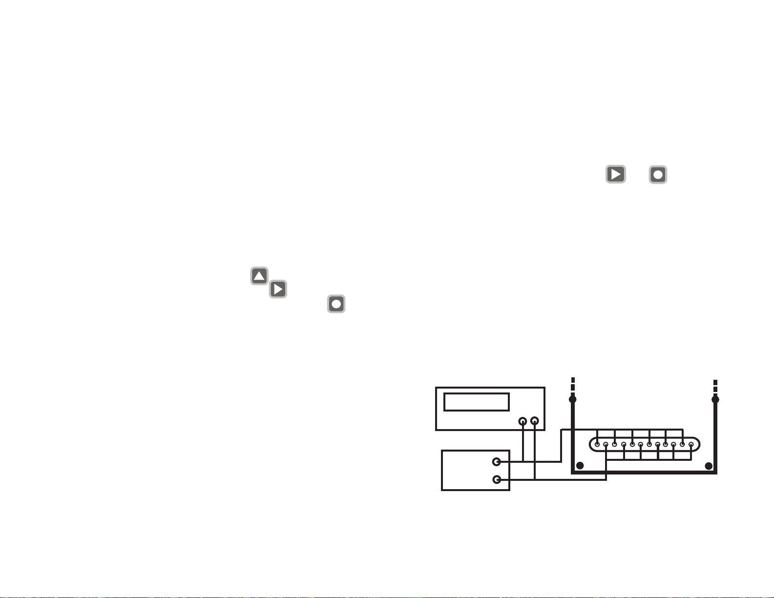
Calibration is performed by inputting DC MV from a low Impedance
source (10 Ohm) and entering the precise value of the MV into the display.
UNIT WIRING:
Using copper wire, connect the positive and negative terminals of the
Input Connector to a precision millivolt meter and a low output
impedance source (10 ohm or less) set to 30mV ±2mV input.
Parallel-connect all thermocouple terminals of the Input Connector as
shown:
(BACK-
3 0. 2 6
+ -
MILLIVOLTMETER
COPPER WIRE
30mV±2mV
NOTE: To avoid any interference during calibration, disconnect
the RS-232 wires from the controller.
36
PLATE)
INPUTS
Page 21
On entering function [78] the function display will read 78.
The upper display shows 30.00 mV setting.
Enter the exact mV as measured by the millivolt meter.
The main display will flash all zero’s. During this period the controller is
checking calibration so do not alter the mV reading. When the flashing
stops, the calibration is complete and the controller will return to
“RUN” Mode.
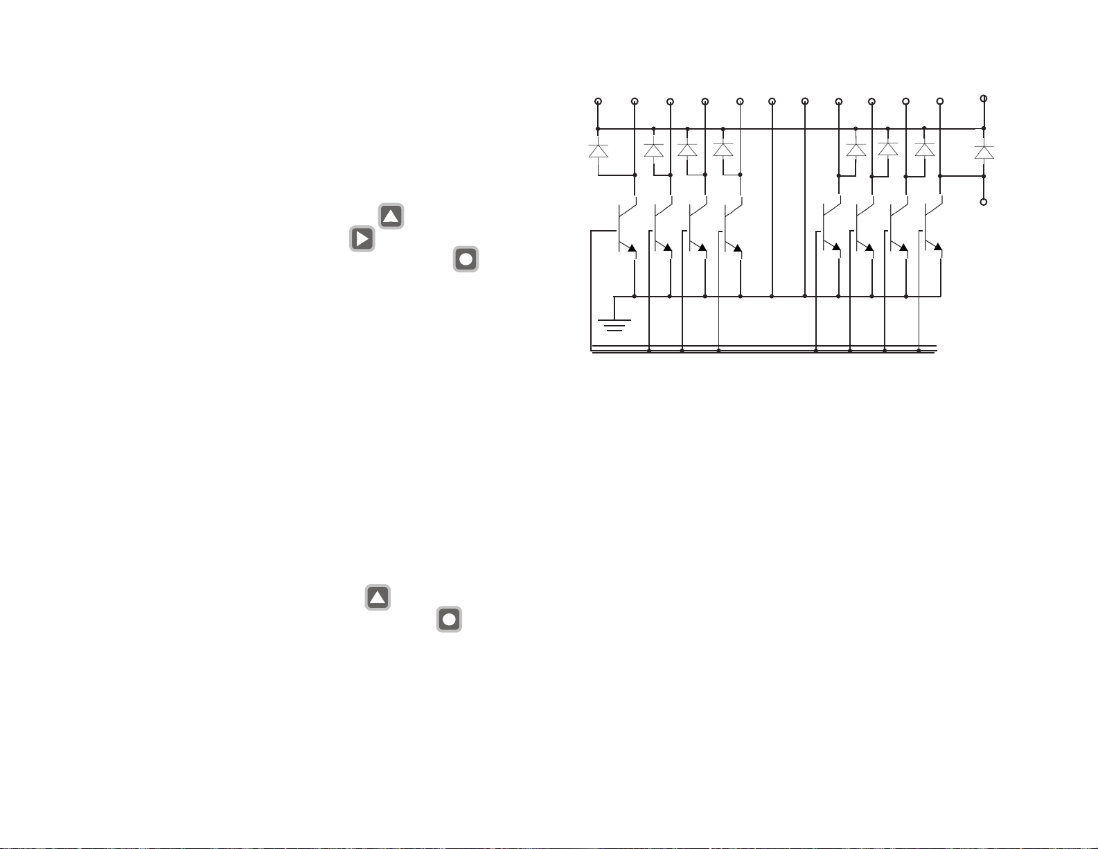
Open Collector Transistor Diagram for Output
External Power supply
DC Z1 Z2 Z3 Z4 C C Z5 Z5 Z6 Z6 Up to 40 VDC
To increment the flashing digit press the button
To advance to the next digit press the button
To save the mV setting and start calibration press the button
6.12 Function [79] Start Profile
Function [79] does not control any other function
On entering function [79] the function display shows 79.
The zone display shows blank.
The upper display shows 0.
By advancing the flashing digit the operator can select
[0] to return with no changes
[1] to [6] to start profile on any one zone 1 to 6
[7] to start profiles on all enabled zones 1 to 6
To increment the flashing digit press the button
To start profile and return to “RUN” mode press the button
5 VDC
Internal
Power
Supply
Microprocessor Bus
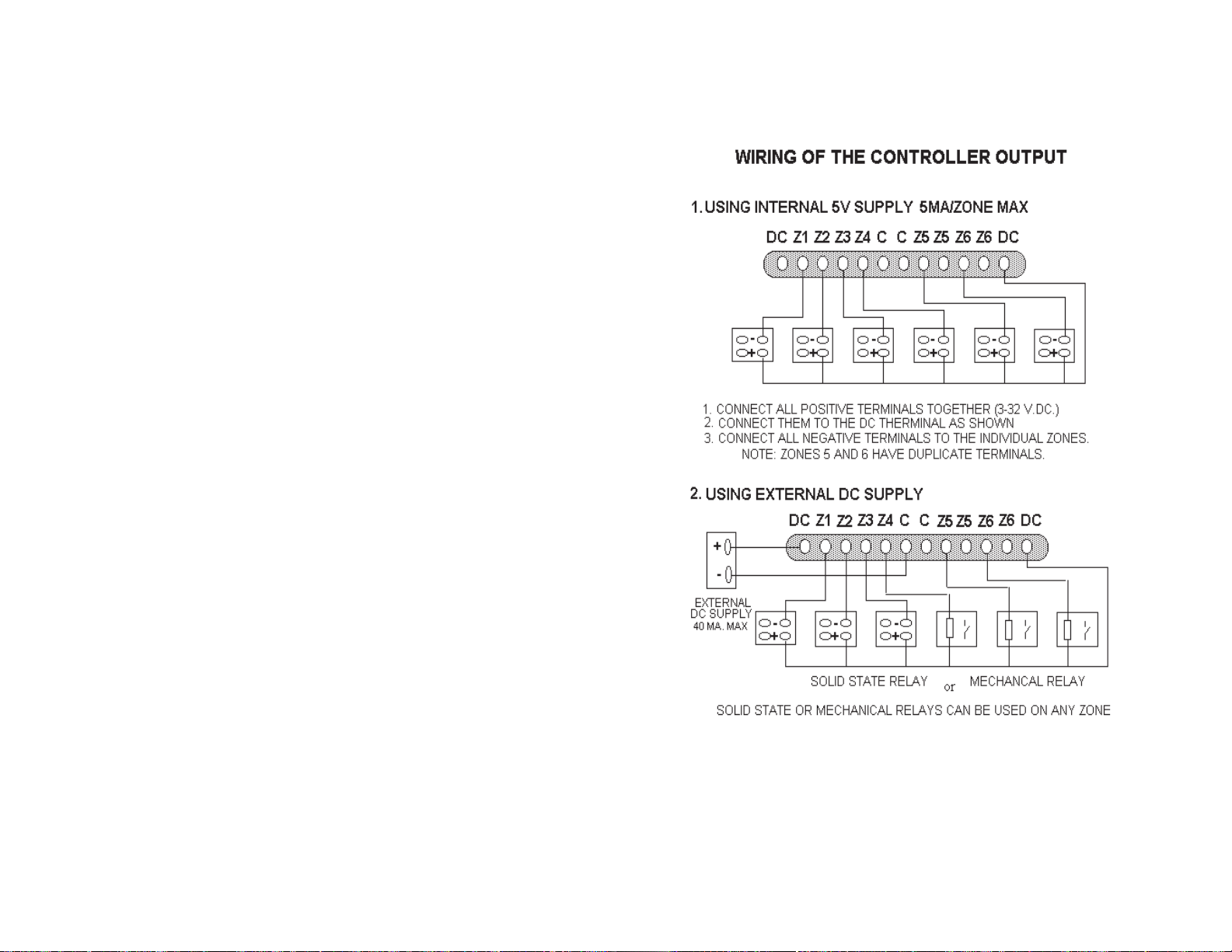
Note ! See page 40 for Wiring Diagram of controller outputs
7.1 Thermocouple Ranges
Standard Ranges [40 Mv]
TC ºC Range ºF Range
B 0-1800 32-3300
C 0-2300 32-4200
E 0 -500 32-1000
J 0-750 32-1400
K 0-1000 32-1900
R 0-1750 32-3200
S 0-1750 32-3200
T 0 -400 32-750
37
Extended Ranges [75 Mv]
E 0-1000 32-1800
K 0-1300 32-2500
Note ! Extended range will work with all Standard range thermocouples, but it is better to use Standard range for thermocouples with
output below 40 Mv .
38
Page 22
SECTION 8
SPECIFICATIONS
No. of Zones Six
Input Range 0-40mV Standard/
0-75mV Expanded
Accuracy ±0.2% Range, ±2°C
Resolution ±5uV
Thermocouple Input selectable B,C,E,J,K,R,S,T
Scale Selectable °C or °F
launaM ro enutotuADIP
Password protection Yes
Profiling [ramp / soak] 20 segments per loop
Control outputs 6 [one per loop]
Output rating :- Internal power 5V DC 10 Ma max
External power 5 to 40V DC 0.5 Amp
Communication RS-232
Communication Software Visual Basic
Zone display time Settable 1 to 40 sec
or Hold on any zone
Alarms Selectable HI - LO - HI/LO or no alarms
Alarm Type Latching or Non Latching
Alarm display Flashing display
Alarm output [deenergises on alarm] Single relay for all zones
Alarm Reset Manual
5gnitar yaleR Amp @ 120 VAC
Display LED 0.6" high
Enclosure 1/4 Din Aluminum, 6" long
Terminals Headers for Plug-in Wiring
Line Power 120/240VAC; 50/60Hz
Power Consumption 10VA Max.
Max. Voltage between Inputs 6VDC or RMS
Open T/C Warning Flashing Display [9999
[Windows]
[zone in alarm]
]
39
40
Page 23

APPLICATION NOTES :
In order to operate CN616 Controller successfully it must be set up
correctly for the application. The unit can be set manually or by the
computer through RS232 link. Up to 10 units can be connected to a
single RS232 port. The computer program is intuitive and does not
require explanation. There are two features that can not be set by the
computer.
1. Calibration. This requires lab setting for accuracy .
2. Unit number. T o avoid conflict in communication.
If number of units are linked together, care must be taken to
avoid duplication of unit identification numbers.
CN616 has 3 operating modes.
1. ST ANDARD MODE
2. RAMP AND SOAK1 [Profile]
3. RAMP AND SOAK2 [Profile]
The difference between RAMP AND SOAK1 & 2 is what happens at
the end of profile run. In RAMP AND SOAK1 after last segment is
finished the power is turned off, while in RAMP AND SOAK2 after
the last segment is finished the temperature will be controlled at the last
setpoint indefinitely or until profile is started again.
ST ANDARD MODE
Setpoints for ST ANDARD MODE are set in function 36.
Each zone runs independently of other zones. I.e.:- zone 1 may have
PID control, zone 2 may have on/off control, and zone 3 may be set to
cooling, [outputs reversed]. The only common things to all zones are
PID parameters and thermocouple type. Any zone can be turned off
during run by function 31.
RAMP AND SOAK [Profile] MODE.
Setpoints for Profile are set in function 75 [01 to 20]
T o run Profile model code must be set to 51 or 52.[function 33]
Until Profile is started by function 79, all zones will run in ST ANDARD
MODE. Function 79 can start Profile for any single zone or all zones at
once.
In profile run control starts at ambient temperature, ambient temperature
becomes first setpoint and is advanced to the first segment setpoint at
the rate of the first segments slope. Profile run will continue until last
segment is reached, as set by function 74. Profile can be restarted at any
time for any one zone or all zones at once.
SETTING CN 616 TC1 TO CONTROL 4 ZONE FURNACE.
Configuration:
Alarms
Zone Setpoint HI LO
1 400ºF 15ºF 20ºF
2 500ºF 15ºF 15ºF
3 530ºF 15ºF 20ºF
4 300ºF 20ºF 20ºF
Alarms Non latching
Thermocouple T ype “K”
Autotune on Zone 2
Heaters, 120 VAC , 500 watt each
Controller power, 120 V AC
Drivers :Solid State Relays ( Omega type SSRL240DC25) or equivalent.
INST ALLATION:-
Install the controller as instructed in the USER GUIDE Manual page 15.
Wire the power terminals - manual page 17
Wire the thermocouples as shown - manual page 20
NOTE :Since it is a 4 zone furnace, use only 4 type “K” thermocouples on
zones 1, 2, 3, &4.
Short terminals 5 & 6 with copper wires. T o avoid shorting thermocouples to the Electric heaters or grounds, use ungrounded and shielded
thermocouples.
Wire controller outputs as shown in the Manual page 40. Use only 4
outputs Z1, Z2, Z3, & Z4. Do not connect anything to terminals Z5
& Z6. Do NOT power the heaters at this time.
41
42
Page 24

Setup - Power the CN 616 controller
1. MODEL SELECTION.
T o comply with the requirements, the following model must be
selected:
Standard control, Hi / Lo Alarm with Non Latching Relay , ºF .
T ype “K” thermocouple
Looking on page 28 in the Manual the model will be coded as: 2 3 0 4.
2 - Hi / Lo Alarm
3 - Non latching relay , *F
0 - Standard control
4 - T ype “K” thermocouple
Using procedure outlined on the inside back cover of this reference
card, load the above model number into the controller .
NOTE If Function 99 appears during setup- it means that the password
protection is enabled. Follow instructions on page 25 of the Manual to
enter the password. Password is factory preset at 1 0 1 1. It may be a
good idea to disable the Password protection at this time. Use procedure on page 27 and load “0” in Function 32. If password protection is
desired, enable the password after the Controller setup is completed.
2. ZONE DISABLE - Page 27
Since only 4 zones are used, zones 5 & 6 should be disabled. Using
setup procedure outlined above set 31 within the Function 71 and
follow the zone enable procedure in the Manual on page 27.
3. ZONE DISPLAY TIME - Page 29
Using the setup procedure outlined above set 35 within Function 71
and follow the Zone display time instructions in the Manual on page 29.
4. SET SETPOINT - Page 29
Using setup procedure outlined on the inside back cover of this reference card, select Function 72 instead of 71. Select sub function 36
(Setpoint) and follow the procedure
On page 29 of the Manual to load the following setpoints :
Z1 - 400 º F
Z2 - 500 º F
Z3 - 530 º F
Z4 - 300 º F
Skip zones 5 & 6.
5. HIGH ALARMS - Page 30
Select Function 72 as above, select sub function 37 (Hi - Alarm).
Follow the procedure Outlined on page 30 in the Manual and set the
following alarms :
Z1 - 15 º F
Z2 - 15 º F
Z3 - 15 º F
Z4 - 20 º F
6. LOW ALARMS - Page 30
Select Function 72 as above, select sub function 38 ( Lo Alarm).
Follow the procedure Since only 4 zones are used, zones 5 & 6
should be disabled. Using setup procedure
Z1 - 20 º F
Z2 - 15 º F
Z3 - 20 º F
Z4 - 20 º F
7. PID CONTROL - Pages 31, 32, 33.
Even with the AUTOTUNE system certain parameters must be set
manually , these are :
CYCLE TIME - Minimum recommended 4 seconds
HYSTERESIS - T ypical 1 º F
PID ZONES - Z1, Z2, Z3, Z4.
COOLING ZONES - None
Using the procedures outlined on pages 31, 32 & 33 of the manual,
load the above numbers.
43
44
Page 25
8. AUTOTUNE SETPOINT AND ZONE - Page 35.
Using setup procedure outlined on the inside cover of this reference
card, select Function 76 instead of 71. Read manual page 35 how
to set and run AUTOTUNE. W rite autotune Set point - 350 º F and
autotune Zone - 2
9. RUN AUTOTUNE - Page 35
Before starting autotune connect power to the heaters. Using the above
procedure Select Function 77 and follow instructions on page 35 of
the Manual. The autotune Process will start and will be completed
within few minutes or few hours depending on the time constants of the
furnace system. Upon completion the controller will Control the temperature of the furnace within the specified parameters.
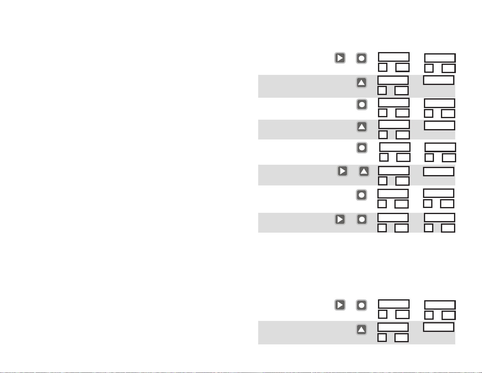
EXAMPLE:Set Number of Profile Segments in each Zone
Action
1.
Enter Setup mode
2.
Select Function 74
(set the number of profile segments
in each zone)
Enter
3.
Confirm Selection
Buttons to use
together
Display Before Display After
0 4 0 3
7 0
5 11
7 1
7 0
7 4
7 0
7 4
=>
=>
=>
=>
7 1
7 0
7 4
7 0
7 4
7 4
SETTING CN 616 TC1 TO CONTROL 4 ZONE FURNACE.
TO RUN IN “RAMP AND SOAK1” MODE [Profile]
The difference between STANDARD MODE and RAMP AND SOAK
MODE is that in RAMP AND SOAK controller can run up to 20 control
segments for each zone. The first segment, for each zone, is made up of
target temperature and rate of change (ramp). Subsequent segments are
made up of setpoint, slope and time. Only one parameter (slope or time)
need to be set. If time is set when new setpoint is different from the
previous one, time will be converted to slope. The other parameter should
be set at 0. If slope is set for the segment with no change in setpoint, the
segment will be ignored and control will go to the next segment.
To run RAMP AND SOAK, CN616TC1 must be installed and set up as
described in STANDARD MODE, then MODEL mode must be
changed to 51 or 52 function 33 [p37]. Set number of segments function
74 [p33]. And set segments function 75 sub function 01 to 20 [p34].
When all is set correctly to run PROFILE it must be started by function
79 [p37]. Until PROFILE is started controller will run in STANDARD
MODE, controlling to the STANDARD MODE setpoint. Function 79
will start profile for any single zone, or all zones at once. In the first
segment starting setpoint is set at the ambient temperature and is changed
at the rate of slope of the first segment.
45
Enter
4.
Set the Number of
Profile Segments
Enter
[the zone number increments
repeat step 4. for the next zone]
EXIT Function
5.
(at any time)
use &
to set # to 00-20
together
7 4
0 0
1
0 5
1
0 5
6
7 4
7 4
7 4
7 4
=>
=>
=>
=>
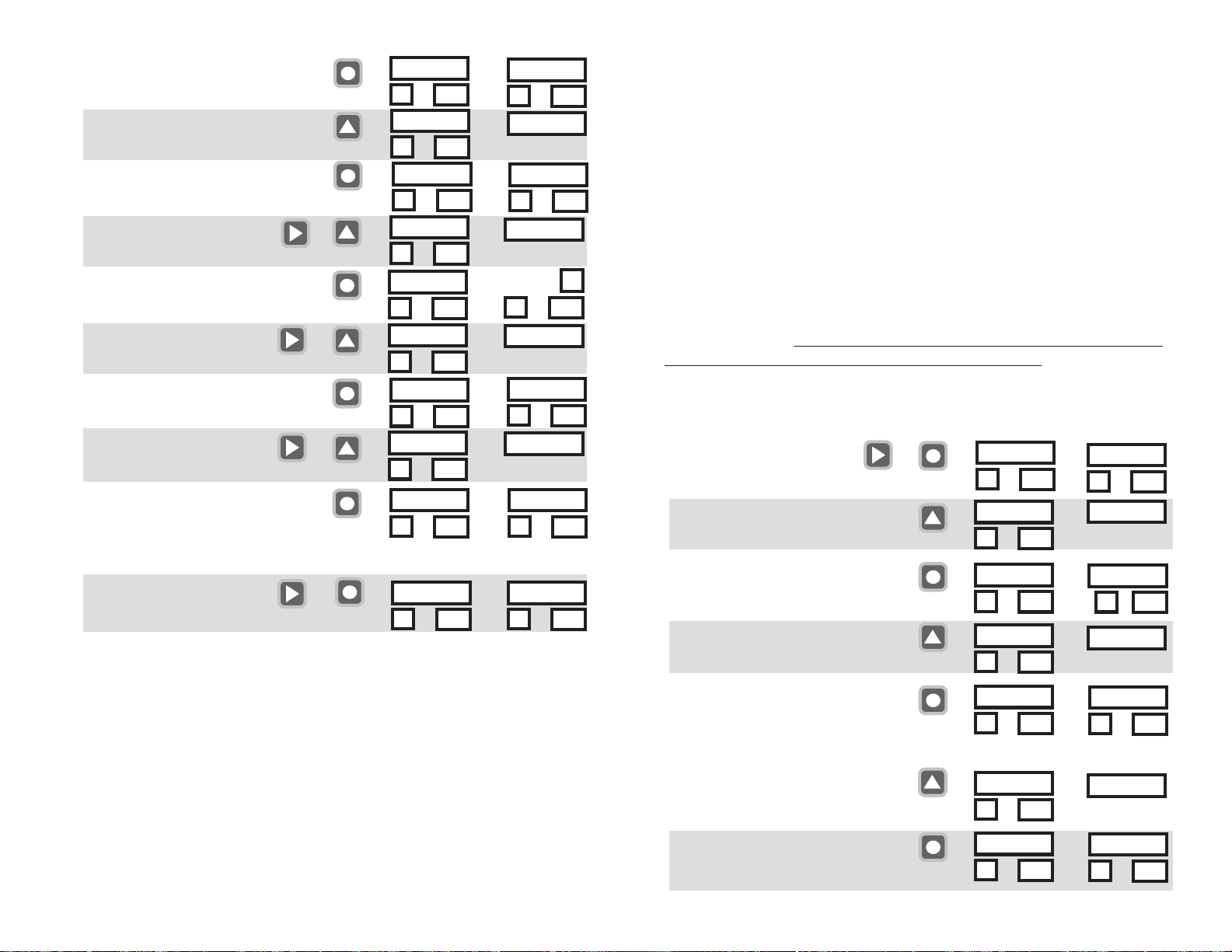
EXAMPLE: Program Profile Segment Settings
Set Profile Setpoint, Slope & Time for each Segment in each
Zone (Large profiles are easily entered using the software.
They can be modified manually using this procedure.)
Action
1.
Enter Setup mode
2.
Select Function 75
(set the profile segment settings
in each zone)
46
Buttons to use
together
Display Before Display After
0 4 0 3
5 11
7 1
7 0
=>
=>
0
1
0 0
0 4 0 3
7 4
0 5
7 42
5 11
7 1
7 0
7 5
Page 26
Enter
3.
Confirm Selection
Enter
Set T emperature
4.
Setpoint
5.
Set Slope
(degrees/min)
Set Time
6.
(hours)
Enter and go to Next segment
setpoint [Repeat Steps 4-6 for
all set segments]
After last segment [set by function 74] go to next zone(S tep 4.)
At any time EXIT
7.
Function
Example: Program a profile with one segment in Zone 1 and two
segments in Zone 2 use Function 74 to set Zone 1 to 01 and Zone
2 to 02 (make sure Zones 1 & 2 are enabled [Function 71\31] any
enabled Zones 3-6 with 00 segments will run under Standard Contr ol). Next
use Function 75 to program the T emperatur e Setpoint in Zone 1
Segment 1 to 300°(Step 4.) Set the Slope to 15.0°/min(S tep 5.)
Set the Time to 05.00/min(S tep 6.) (Time is ignored for control
purposes when the Slope(Step 5.) in the segment is not 0.00°/min)
There are no other segments in Zone 1. Pr ess enter in Step 6. the
Zone display(lower left) on the controller will change to program
Zone 2 Segment 1(Step 4.) Program the settings for Zone 2. Start
the profile with Function 79.(A Zone will maintain the T emperature of the end segment in a profile indefinitely in Ramp&Soak 2)
47
to set # to 0000-9999
Enter
to set # to 00.0-99.9
Enter
to set # to 00.00-99.99
use &
use &
use &
together
7 5
7 0
7 0
7 5
7 5
7 5
0 0 0 0
1
0 1
0 4 0 0
0 1
0 0 0
0 11
0 1.5
0 11
0 0 0 0
0 11
0 1.5
0 11
0 1.5
0 86
=>
=>
=>
=>
=>
=>
=>
=>
=>
=>
7 0
7 5
1
0 4 0 0
0 0 0 0
1
0 1.5
0 0.0 0
0 0.0 0
0 0 0 0
0 4 0 3
7 5
0 1
0 1
0 11
0 11
0 21
5 11
To run RAMP AND SOAK CN616TC1 MODEL the mode must
be set to 51 or 52[Function 71\31]. Number of segments must be
set for each enabled zone[Function 74]. Setting the number of
segments to “00” will set that zone to run in STANDARD mode.
PROFILE can only be started from Function 79 or the software.
NOTE: For each zone until the PROFILE is started the controller
will run that zone in STANDARD MODE, controlling at the
STANDARD MODE setpoint.
Function 79 will start the profile for any single zone, or all zones
at once. In the first segment the starting setpoint is set at the
ambient temperature and is changed at the rate of slope of the
first segment until the first segment setpoint is reached.
IMPORTANT!! To avoid overheating, zones intended for Profile
run MUST have their Standard Setpoints set to 0. [Function 36]
EXAMPLE: Start Profile [Function 79]
Action
Enter Setup mode
1.
2.
Select Function 79
Enter
3.
Select ONE Zone
to Start Pr ofile Run
Enter
[Start zone 5 Profile]
Buttons to use
together
Display Before Display After
0 4 0 3
=>
5 11
7 1
=>
7 0
7 9
7 9
0
7 9
0 5
7 9
0
=>
=>
5
0 4 0 3
=>
OR
7 9
7 9
=>
7
0 4 0 3
=>[Start run on all enabled zones
Select ALL Zones
3.
to Start Pr ofile Run
Enter
with 1 or more segments in the Profile]
48
0
0 7
7 1
7 0
7 9
7 9
5 11
5 11
Page 27

WARRANTY/DISCLAIMER
OMEGA ENGINEERING, INC. warrants this unit to be free of defects in materials and workmanship for a
period of 13 months from date of purchase. OMEGA’s WARRANTY adds an additional one (1) month grace
period to the normal one (1) year product warranty to cover handling and shipping time. This ensures
that OMEGA’s customers receive maximum coverage on each product.
If the unit malfunctions, it must be returned to the factory for evaluation. OMEGA’s Customer Service
Department will issue an Authorized Return (AR) number immediately upon phone or written request.
Upon examination by OMEGA, if the unit is found to be defective, it will be repaired or replaced at no
charge. OMEGA’s WARRANTY does not apply to defects resulting from any action of the purchaser,
including but not limited to mishandling, improper interfacing, operation outside of design limits,
improper repair, or unauthorized modification. This WARRANTY is VOID if the unit shows evidence of
having been tampered with or shows evidence of having been damaged as a result of excessive corrosion;
or current, heat, moisture or vibration; improper specification; misapplication; misuse or other operating
conditions outside of OMEGA’s control. Components in which wear is not warranted, include but are not
limited to contact points, fuses, and triacs.
OMEGA is pleased to offer suggestions on the use of its various products. However,
OMEGA neither assumes responsibility for any omissions or errors nor assumes liability for
any damages that result from the use of its products in accordance with information provided
by OMEGA, either verbal or written. OMEGA warrants only that the parts manufactured by the
company will be as specified and free of defects. OMEGA MAKES NO OTHER WARRANTIES OR
REPRESENTATIONS OF ANY KIND WHATSOEVER, EXPRESSED OR IMPLIED, EXCEPT THAT OF
TITLE, AND ALL IMPLIED WARRANTIES INCLUDING ANY WARRANTY OF MERCHANTABILITY
AND FITNESS FOR A PARTICULAR PURPOSE ARE HEREBY DISCLAIMED. LIMITATION OF
LIABILITY: The remedies of purchaser set forth herein are exclusive, and the total liability of
OMEGA with respect to this order, whether based on contract, warranty, negligence,
indemnification, strict liability or otherwise, shall not exceed the purchase price of the
component upon which liability is based. In no event shall OMEGA be liable for
consequential, incidental or special damages.
CONDITIONS: Equipment sold by OMEGA is not intended to be used, nor shall it be used: (1) as a “Basic
Component” under 10 CFR 21 (NRC), used in or with any nuclear installation or activity; or (2) in medical
applications or used on humans. Should any Product(s) be used in or with any nuclear installation or
activity, medical application, used on humans, or misused in any way, OMEGA assumes no responsibility
as set forth in our basic WARRANTY/DISCLAIMER language, and, additionally, purchaser will indemnify
OMEGA and hold OMEGA harmless from any liability or damage whatsoever arising out of the use of the
Product(s) in such a manner.
RETURN REQUESTS/INQUIRIES
Direct all warranty and repair requests/inquiries to the OMEGA Customer Service Department. BEFORE
RETURNING ANY PRODUCT(S) TO OMEGA, PURCHASER MUST OBTAIN AN AUTHORIZED RETURN (AR)
NUMBER FROM OMEGA’S CUSTOMER SERVICE DEPARTMENT (IN ORDER TO AVOID PROCESSING
DELAYS). The assigned AR number should then be marked on the outside of the return package and on any
correspondence.
The purchaser is responsible for shipping charges, freight, insurance and proper packaging to prevent
breakage in transit.
FOR WARRANTY RETURNS, please have the
following information available BEFORE contacting
OMEGA:
1. Purchase Order number under which the product
was PURCHASED,
2. Model and serial number of the product under
warranty, and
3. Repair instructions and/or specific problems
relative to the product.
OMEGA’s policy is to make running changes, not model changes, whenever an improvement is possible. This affords our
customers the latest in technology and engineering.
OMEGA is a registered trademark of OMEGA ENGINEERING, INC.
© Copyright 2017 OMEGA ENGINEERING, INC. All rights reserved. This document may not be copied, photocopied,
reproduced, translated, or reduced to any electronic medium or machine-readable form, in whole or in part, without the prior
written consent of OMEGA ENGINEERING, INC.
FOR NON-WARRANTY REPAIRS, consult
OMEGA for current repair charges. Have
the following information available BEFORE
contacting OMEGA:
1. Purchase Order number to cover the COST
of the repair,
2. Model and serial number of the product, and
3. Repair instructions and/or specific problems
relative to the product.
Page 28

Where Do I Find Everything I Need for
Process Measurement and Control?
OMEGA…Of Course!
Shop online at omega.com
TEMPERATURE
MU
Thermocouple, RTD & Thermistor Probes, Connectors,
Panels & Assemblies
MU
Wire: Thermocouple, RTD & Thermistor
MU
Calibrators & Ice Point References
MU
Recorders, Controllers & Process Monitors
MU
Infrared Pyrometers
PRESSURE, STRAIN AND FORCE
MU
Transducers & Strain Gages
MU
Load Cells & Pressure Gages
MU
Displacement Transducers
MU
Instrumentation & Accessories
FLOW/LEVEL
MU
Rotameters, Gas Mass Flowmeters & Flow Computers
MU
Air Velocity Indicators
MU
Turbine/Paddlewheel Systems
MU
Totalizers & Batch Controllers
SM
pH/CONDUCTIVITY
MU
pH Electrodes, Testers & Accessories
MU
Benchtop/Laboratory Meters
MU
Controllers, Calibrators, Simulators & Pumps
MU
Industrial pH & Conductivity Equipment
DATA ACQUISITION
MU
Communications-Based Acquisition Systems
MU
Data Logging Systems
MU
Wireless Sensors, Transmitters, & Receivers
MU
Signal Conditioners
MU
Data Acquisition Software
HEATERS
MU
Heating Cable
MU
Cartridge & Strip Heaters
MU
Immersion & Band Heaters
MU
Flexible Heaters
MU
Laboratory Heaters
ENVIRONMENTAL
MONITORING AND CONTROL
MU
Metering & Control Instrumentation
MU
Refractometers
MU
Pumps & Tubing
MU
Air, Soil & Water Monitors
MU
Industrial Water & Wastewater Treatment
MU
pH, Conductivity & Dissolved Oxygen Instruments
M3321/0517
 Loading...