

Page 1
TM
NORWALK, CT
User’s Guide
Shop online at
omega.com
e-mail: [email protected]
For latest product manuals:
www.omegamanual.info
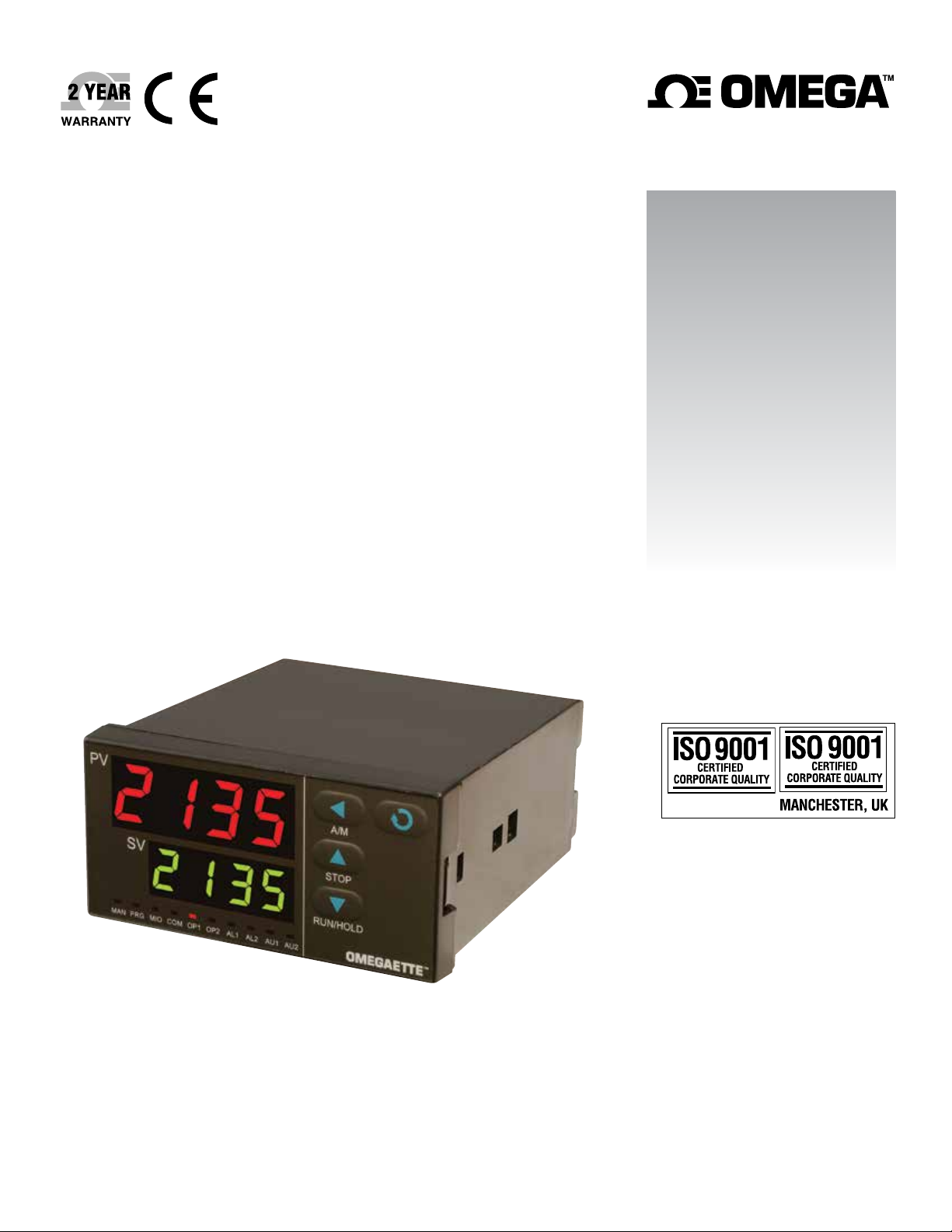
CN4000 SERIES
Temperature Controllers
Page 2

omega.com [email protected]
Servicing North America:
U.S.A. Omega Engineering, Inc.
Headquarters: Toll-Free: 1-800-826-6342 (USA & Canada only)
Customer Service: 1-800-622-2378 (USA & Canada only)
Engineering Service: 1-800-872-9436 (USA & Canada only)
Tel: (203) 359-1660 Fax: (203) 359-7700
e-mail: [email protected]
For Other Locations Visit omega.com/worldwide
The information contained in this document is believed to be correct, but OMEGA accepts no liability for any errors it contains, and reserves
the right to alter specifications without notice.
Page 3
CONTENTS
MODEL CONFIGURATION…….………………………………………….…………….2
SPECIFICATIONS………………………………………………………………….……..3
PARAMETER AND SETTING……………………………………………………………4
SYMBOL DESCRIPTIONS…………………………………………..…………………..7
INSTRUMENT INSTALLATION AND WIRING……..………………………….………8
DISPLAY AND OPERATIONS…………………………………………...……….……..9
OPERATION DESCRIPTION……………….…………………..……………….….…10
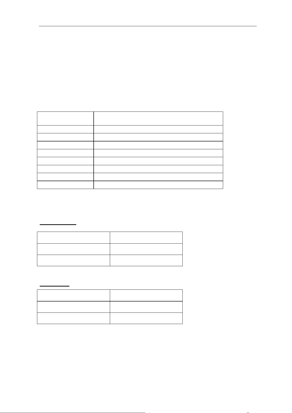
MODEL CONFIGURATION
Model Description
CN4116 (*)-(**)-(***)
CN4216 (*)-(**)-(***)
CN414 (*)-(**)-(***)
CN424 (*)-(**)-(***)
CN418V (*)-(**)-(***)
CN428V (*)-(**)-(***)
CN418H (*)-(**)-(***)
CN428H (*)-(**)-(***)
* Specify controlling output code from Output Options table below
** Specify alarm code from Alarm Options table below
*** Low voltage power supply option (-LV)
1/16 DIN controller
1/16 DIN controller, with 0.0 decimal
1/4 DIN controller
1/4 DIN controller, with 0.0 decimal
1/8 DIN Vertical controller
1/8 DIN Vertical controller, with 0.0 decimal
1/8 DIN Horizontal controller
1/8 DIN Horizontal controller, with 0.0 decimal
Controlling Output Options
Option Type Code
Relay -R1
DC SSR driver -DC1
Alarming Output Options
Option Type Code
Relay -R2
DC SSR driver -DC2
Low voltage power supply option
-LV 24V AC/DC, 50/60 Hz
2
Page 4
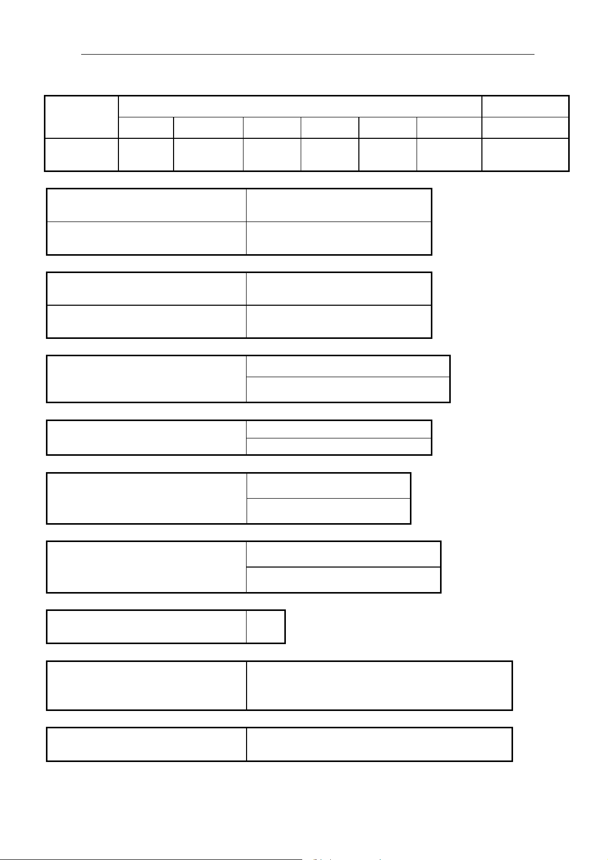
SPECIFICATIONS
Input Type
K S R E J N PT100
Range ℃/ ℉
0 to1300 ℃
32 to 2372 ℉
0 to1700℃
32 to 3092 ℉
Accuracy:
CN 4116/CN414/CN418
CN4216/CN424/CN428
Temperature Display Resolution
CN 4116/CN414/CN418
CN4216/CN424/CN428
Control Method
Thermocouple RTD
0 to1600℃
32 to 2412 ℉
0 to1000℃
32 to 1832 ℉
0 to1200℃
32 to 2192 ℉
0 to 1300℃
32 to 2372 ℉
-200 to 800℃
-328 to 1472 ℉
0.3%FS ± 1℃/1.8°F
0.3%FS ± 0.1℃/0.18°F
1℃/1℉
0.1℃/0.1℉
ON / OFF Control
AI PID Control with Auto Tuning (AT)
Output Type
Alarm
(Modularization)
Supply Voltage
Power Consumption
Operating Environments
Relay Output (1A/250VAC)
Voltage Output for SSR(12V/30mA)
Limit High / Low
High deviation/Low deviation
100~240VAC (-15%, +10%), or 24VDC
50 to 60Hz
≦ 3W
Temperature: -10 to +60℃ / 14 to 140℉
Humidity: 0~90RH%
Electromagnetic compatibility
(EMC)
IEC61000-4-4: ± 4KV/5KHz
IEC61000-4-5: 4KV
3
Page 5
P ARAMETER AND SETTING
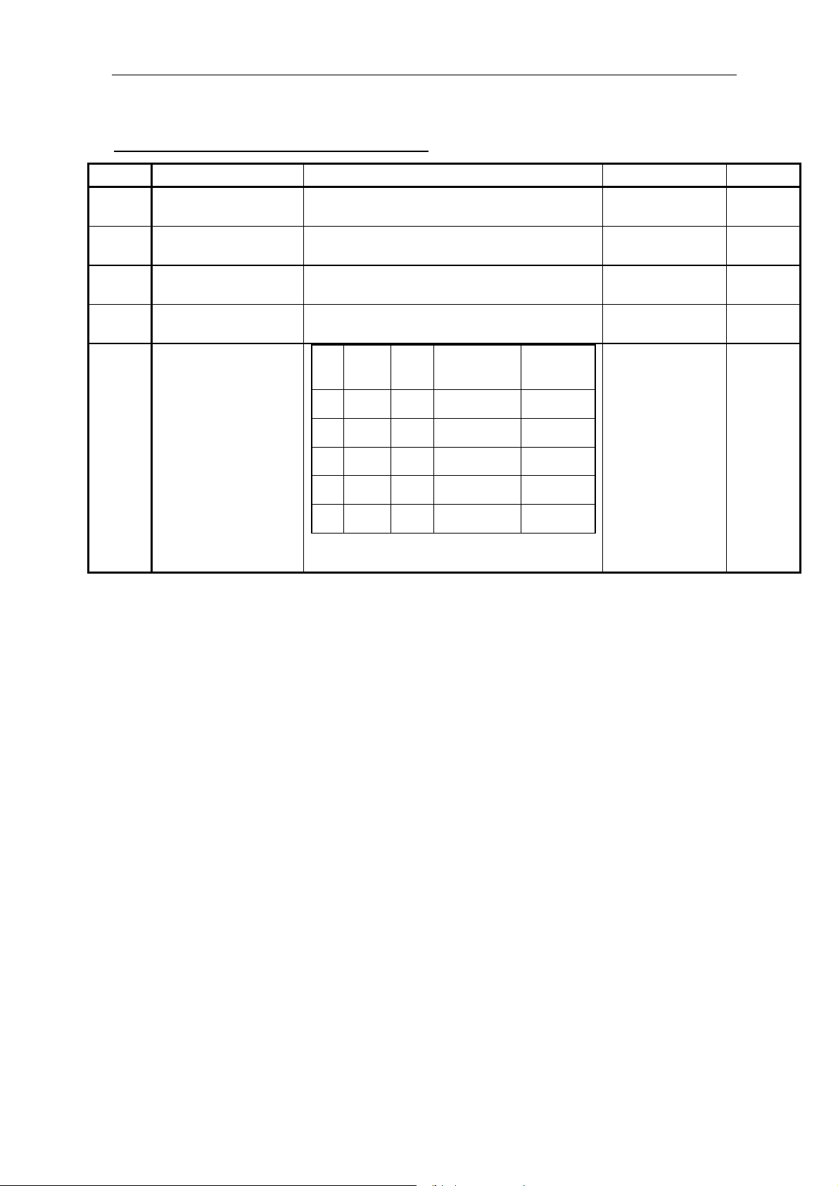
Field parameter table (Primary parameters)
Code Description Remarks Setting Range Default
HIAL High limit alarm
LoAL Low limit alarm
HdAL
LdAL
Deviation high
alarm
Deviation low
alarm
Alarm on when PV>HIAL
alarm off when PV<HIAL- AHYS
Alarm on when PV<LoAL;
alarm off when PV>LoAL + AHYS
Alarm on when PV-SV>HdAL;
alarm off when PV-SV<HdAL - AHYS
Alarm on when PV-SV<LdAL;
alarm off when PV-SV>LdAL + AHYS
-999~+3000 3000
-999~+3000 -999
-999~+3000 3000
-999~+3000 -999
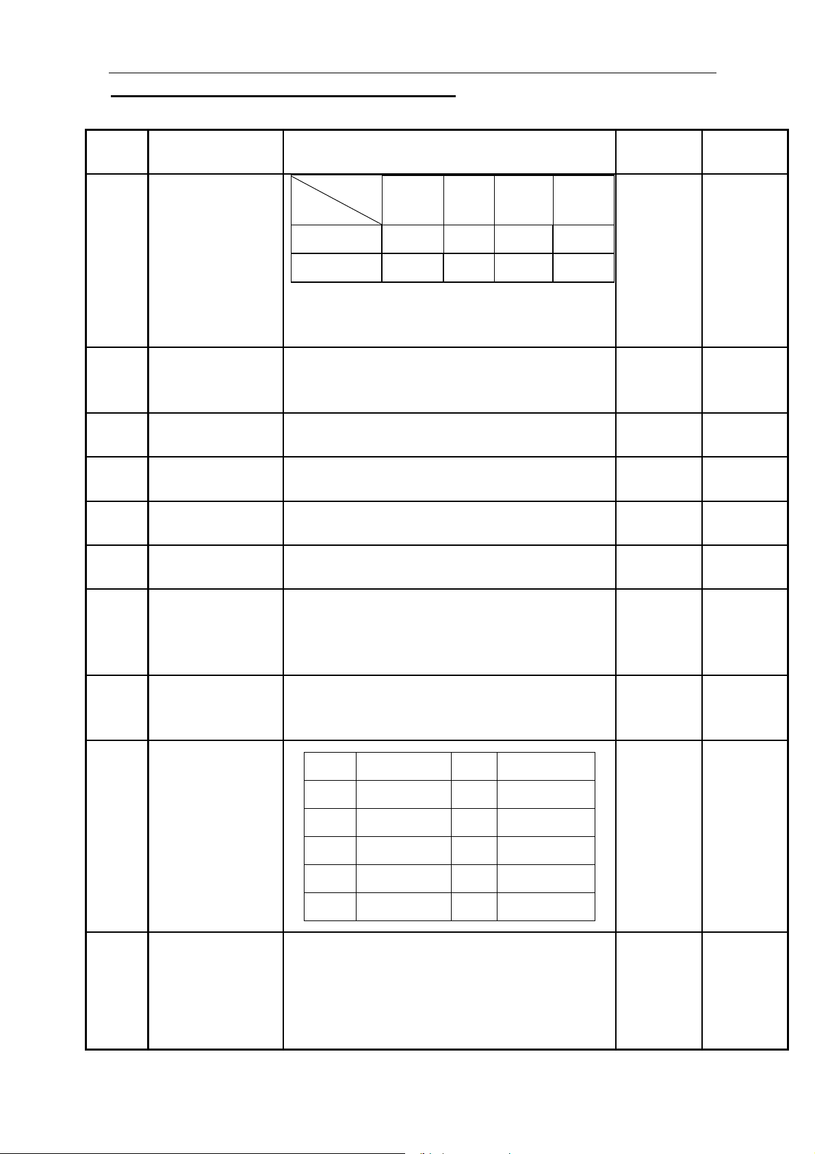
Loc Parameter Lock
Loc
0
1
2
3
808
Auto
Tuning
SV
X
X X
X X X
X X X X
Primary
Parameter
Secondary
Parameter
: allow to modify data or execute AT
X : not allow to modify data or execute AT
0~255 0
4
Page 6
System parameter table (Secondary parameters)
Set the parameter ‘Loc’=808 to enter:
AHYS
Alarm Hysteresis
Avoid frequent alarm on-off action because of the
fluctuation of PV
0~200 2
AOP
Alarm output
assignment
CtrL Control mode
Act
P
I
d
Proportion band
NA No any function on this model.
Time of Integral No integral effect when I=0
Time of
derivative
CtI Control period
CHYS
Control
hysteresis
Alarm
Output to
None
AL1
LdAL
(x 1000)
HdAL
(x100)
LoAL
(x10)
HIAL
(x1)
0 0 0 0
1 1 1 1
eg: AOP=1101 means LdAL, HdAL and HIAL
alarm action output from AL1;LoAL, no alarm
action.
onoF : On-off control
APId : AI PID control, high precision
and no-overshot
Proportion band in PID with unit ℃ or ℉
No derivative effect when d=0
Small value can improve control accuracy. For
SSR output, generally 0.5 to 3 seconds.
Large value can increase using life of relay. For
Relay output, generally 15 to 40 seconds.
CHYS is used for ON-OFF Control.
PV > SV, Output turns OFF;
PV<SV-CHYS, Output turns ON.
1111
0~1111
or
according
to fixed
module
onoF,
APId
rE/dr/
rEbA/drbA
APId
rE
1~999 30
0~9999
Sec
0~999.9
Sec
0.5~120
Sec
100 s
50.0s
2 s
Or
20 s
0~200 2
InP
dPt
Input
specification
Resolution
(only for CN42
series )
InP Input spec. InP Input spec.
0 K 1 S
2 R 3 Spare
4 E 5 J
6 Spare 7 N
8-20 Spare 21 Pt100
0 : 1 ℃/℉
0.0 : 0.1 ℃/℉
5
1~21 0
0.0
Page 7

Scb
FILt
Input Shift
PV input filter
Parameter Scb is used to make input shift to
compensate the error produced by sensor or input
signal itself.
PV-after-compensation=
PV-before-compensation + Scb.
The value of FILt will determine the ability of
filtering noise.
When a large value is set, the measurement input
is stabilized but the response speed is slow.
Generally, if great interference exists, then you
can increase parameter “FILt” gradually to make
momentary fluctuation of measured value less
than 2 to 5.
When the meter of the instrument is being
examined at laboratory, “FILt” should be set to 0
or 1 to short the response time.
50C: 50Hz, ℃
-199~
+400
0
0~40 1
Fru
SPL
SPH
Selection of power
50F: 50Hz, ℉
frequency and
temperature scale
60C: 60Hz, ℃
60F: 60Hz, ℉
Low limit of SV
Upper limit of SV
50C, 50F,
60C, 60F
-999~
3000
-999~
3000
50C
0
400
6
Page 8
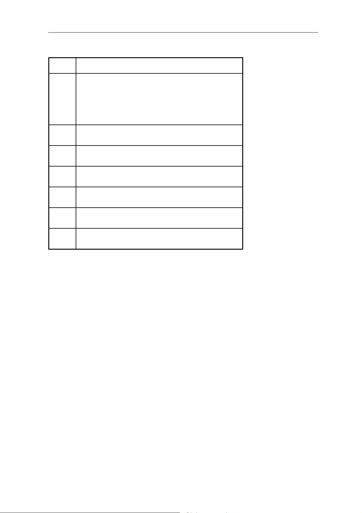
SYMBOL DESCRIPTIONS
Symbol Description
Input specification setting is incorrect
Or
orAL
HIAL High limit alarm
LoAL Low limit alarm
HdAL Deviation high alarm
LdAL Deviation low alarm
Input wiring is disconnected/ thermocouple problem
Or
Short circuited
EErr IC Software error
8888 IC Software error
7
Page 9
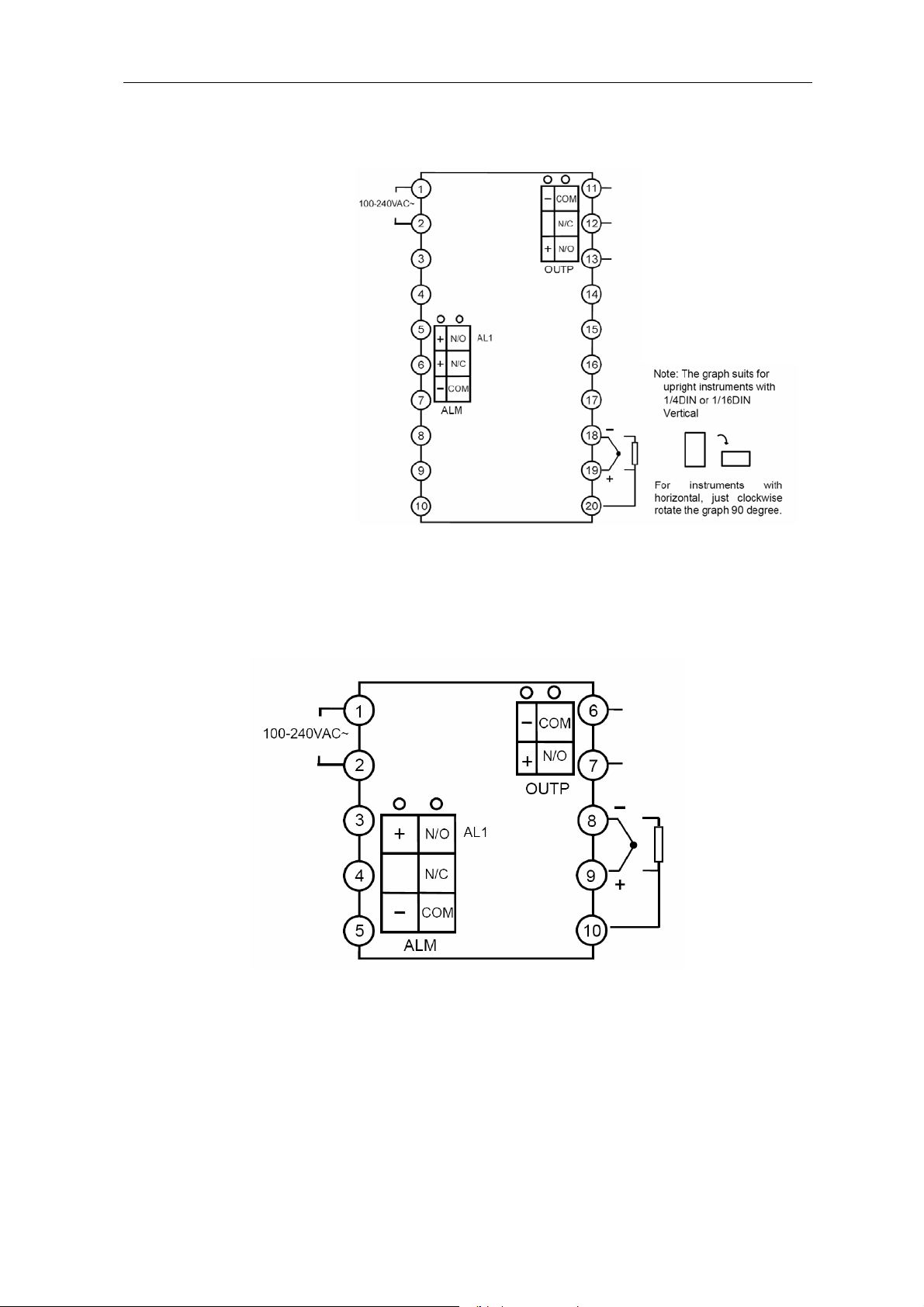
INSTRUMENT INSTALLATION AND WIRING
Wiring graph for instruments with dimension 1/4 DIN; 1/8 DIN Vertical and Horizontal
Note: The compensation
wires for different kinds of
thermocouple are different,
and should be directly connect
to the terminals. Connecting
the common wire between the
compensation wire and the
terminals will cause
measurement error.
Wiring graph for 1/16 DIN dimension instruments:
8
Page 10
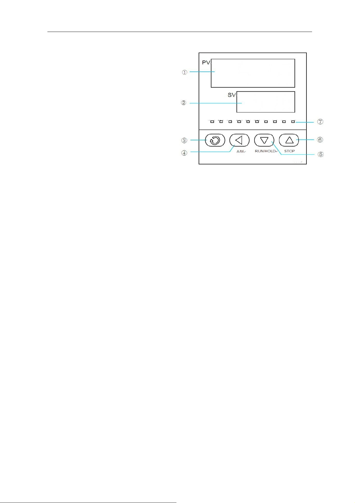
DISPLAY AND OPERATIONS
① Upper display window, displays PV,
parameter code, etc.
② Lower display window, displays SV,
parameter value, or alarm
③ Setup key, for accessing parameter
table and conforming parameter
modification.
④ Data shift key, and auto tuning.
⑤ Data decrease key
⑥ Data increase key
⑦ LED indicator. MAN, PRG, MIO,
COM, OP2, AL2, AU1 and AU2
Com indicators is non-applicable.
OP1 and AL1 will indicate I/O operation of the corresponding module.
Basic display status:
When power on, the upper display window of the instrument shows the process
value (PV), and the lower window shows the set-point (SV). This status is called
basic display status.
When the input signal is out of the measurable range (for example, the
thermocouple or RTD circuit is break, or input specification sets wrong), the upper
display window will alternately display “orAL” and the high limit or the low limit of PV,
and the instrument will automatically stop output. If the lower display window
alternately display “HIAL”, “LoAL”, “HdAL” or “LdAL”, it means high limit alarm, low
limit alarm, deviation high alarm, and deviation low alarm happening.
9
Page 11
OPERATION DESCRIPTION
z Set Value Setting:
In basal display status, if the parameter lock “Loc” isn't locked, we can set
setpoint (SV) by pressing 、 or . Press key to decrease the
value, key to increase the value, and key to move to the digit expected
to modify. Keep pressing or , the speed of decreasing or inscreasing
value get quick. The range of setpoint is between the parameter SPL and SPH.
The default range is 0~400.
z Parameter Setting:
In basal display status, press and hold for about 2 seconds can access
Field Parameter Table. Pressing can go to the next parameter; pressing
、 or can modify a parameter. Press and hold can return to
the preceding parameter. Press (don't release) and then press key
simultaneously can escape from the parameter table. The instrument will
escape auomatically from the parameter table if no key is pressed within 30
seconds. Setting Loc=808 and then press can access System
Parameter Table.
● AI artificial intelligence control and auto tuning
When AI artificial intelligence control method is chosen (CtrL=APId), the PID
parameters can be obtained by running auto-tuning. In basal display status,
press for 2 seconds, the “At” parameter will appear. Press to change
the value of At from “oFF” to “on”, then press to active the auto-tuning
process. During auto tuning, the instrument executes on-off control. After 2-3
times of on-off action, the instrument will obtain the optimal control parameter
value. If you want to escape from auto tuning status, press and hold the
key for about 2 seconds until the "At" parameter appear again. Change “At”
from “on” to “oFF”, press to confirm, then the auto tuning process will be
cancelled.
Note 1: If the setpoint is different, the parameters obtained from auto-tuning are
possible different. So you’d better set setpoint to an often-used value or
middle value first, and then start auto-tuning. For the ovens with good
heat preservation, the setpoint can be set at the highest applicable
temperature. Depending on the system, the auto-tuning time can be
from several seconds to several hours.
Note 2: Parameter Ctl (on-off differential, control hysteresis) has influence on the
accuracy of auto-tuning. Generally, the smaller the value of Ctl, the
higher the precision of auto tuning. But Ctl parameter value should be
large enough to prevent the instrument from error action around setpoint
due to the oscillation of input. Ctl is recommended to be 2.0.
Note 3: The instrument has the function of self-learning. It is able to learn the
process while working. The control effect at the first run after auto tuning
is probably not perfect, but excellent control result will be obtained after a
period of time because of self-learning.
10
Page 12

WARRANTY/DISCLAIMER
OMEGA ENGINEERING, INC. warrants this unit to be free of defects in materials and workmanship for a
period of 25 months from date of purchase. OMEGA’s WARRANTY adds an additional one (1) month grace
period to the normal two (2) year product warranty to cover handling and shipping time. This ensures
that OMEGA’s customers receive maximum coverage on each product.
If the unit malfunctions, it must be returned to the factory for evaluation. OMEGA’s Customer Service
Department will issue an Authorized Return (AR) number immediately upon phone or written request.
Upon examination by OMEGA, if the unit is found to be defective, it will be repaired or replaced at no
charge. OMEGA’s WARRANTY does not apply to defects resulting from any action of the purchaser,
including but not limited to mishandling, improper interfacing, operation outside of design limits,
improper repair, or unauthorized modification. This WARRANTY is VOID if the unit shows evidence of
having been tampered with or shows evidence of having been damaged as a result of excessive corrosion;
or current, heat, moisture or vibration; improper specification; misapplication; misuse or other operating
conditions outside of OMEGA’s control. Components in which wear is not warranted, include but are not
limited to contact points, fuses, and triacs.
OMEGA is pleased to offer suggestions on the use of its various products. However,
OMEGA neither assumes responsibility for any omissions or errors nor assumes liability for
any damages that result from the use of its products in accordance with information provided
by OMEGA, either verbal or written. OMEGA warrants only that the parts manufactured by the
company will be as specified and free of defects. OMEGA MAKES NO OTHER WARRANTIES OR
REPRESENTATIONS OF ANY KIND WHATSOEVER, EXPRESSED OR IMPLIED, EXCEPT THAT OF
TITLE, AND ALL IMPLIED WARRANTIES INCLUDING ANY WARRANTY OF MERCHANTABILITY
AND FITNESS FOR A PARTICULAR PURPOSE ARE HEREBY DISCLAIMED. LIMITATION OF
LIABILITY: The remedies of purchaser set forth herein are exclusive, and the total liability of
OMEGA with respect to this order, whether based on contract, warranty, negligence,
indemnification, strict liability or otherwise, shall not exceed the purchase price of the
component upon which liability is based. In no event shall OMEGA be liable for
consequential, incidental or special damages.
CONDITIONS: Equipment sold by OMEGA is not intended to be used, nor shall it be used: (1) as a “Basic
Component” under 10 CFR 21 (NRC), used in or with any nuclear installation or activity; or (2) in medical
applications or used on humans. Should any Product(s) be used in or with any nuclear installation or
activity, medical application, used on humans, or misused in any way, OMEGA assumes no responsibility
as set forth in our basic WARRANTY/DISCLAIMER language, and, additionally, purchaser will indemnify
OMEGA and hold OMEGA harmless from any liability or damage whatsoever arising out of the use of the
Product(s) in such a manner.
RETURN REQUESTS/INQUIRIES
Direct all warranty and repair requests/inquiries to the OMEGA Customer Service Department. BEFORE
RETURNING ANY PRODUCT(S) TO OMEGA, PURCHASER MUST OBTAIN AN AUTHORIZED RETURN (AR)
NUMBER FROM OMEGA’S CUSTOMER SERVICE DEPARTMENT (IN ORDER TO AVOID PROCESSING
DELAYS). The assigned AR number should then be marked on the outside of the return package and on any
correspondence.
The purchaser is responsible for shipping charges, freight, insurance and proper packaging to prevent
breakage in transit.
FOR WARRANTY RETURNS, please have the
following information available BEFORE contacting
OMEGA:
1. Purchase Order number under which the product
was PURCHASED,
2. Model and serial number of the product under
warranty, and
3. Repair instructions and/or specific problems
relative to the product.
OMEGA’s policy is to make running changes, not model changes, whenever an improvement is possible. This affords our
customers the latest in technology and engineering.
OMEGA is a trademark of OMEGA ENGINEERING, INC.
© Copyright 2018 OMEGA ENGINEERING, INC. All rights reserved. This document may not be copied, photocopied,
reproduced, translated, or reduced to any electronic medium or machine-readable form, in whole or in part, without the prior
written consent of OMEGA ENGINEERING, INC.
FOR NON-WARRANTY REPAIRS, consult
OMEGA for current repair charges. Have
the following information available BEFORE
contacting OMEGA:
1. Purchase Order number to cover the COST
of the repair,
2. Model and serial number of the product, and
3. Repair instructions and/or specific problems
relative to the product.
Page 13

Where Do I Find Everything I Need for
Process Measurement and Control?
OMEGA…Of Course!
Shop online at omega.com
TEMPERATURE
MU
Thermocouple, RTD & Thermistor Probes, Connectors,
Panels & Assemblies
MU
Wire: Thermocouple, RTD & Thermistor
MU
Calibrators & Ice Point References
MU
Recorders, Controllers & Process Monitors
MU
Infrared Pyrometers
PRESSURE, STRAIN AND FORCE
MU
Transducers & Strain Gages
MU
Load Cells & Pressure Gages
MU
Displacement Transducers
MU
Instrumentation & Accessories
FLOW/LEVEL
MU
Rotameters, Gas Mass Flowmeters & Flow Computers
MU
Air Velocity Indicators
MU
Turbine/Paddlewheel Systems
MU
Totalizers & Batch Controllers
pH/CONDUCTIVITY
MU
pH Electrodes, Testers & Accessories
MU
Benchtop/Laboratory Meters
MU
Controllers, Calibrators, Simulators & Pumps
MU
Industrial pH & Conductivity Equipment
DATA ACQUISITION
MU
Communications-Based Acquisition Systems
MU
Data Logging Systems
MU
Wireless Sensors, Transmitters, & Receivers
MU
Signal Conditioners
MU
Data Acquisition Software
HEATERS
MU
Heating Cable
MU
Cartridge & Strip Heaters
MU
Immersion & Band Heaters
MU
Flexible Heaters
MU
Laboratory Heaters
ENVIRONMENTAL
MONITORING AND CONTROL
MU
Metering & Control Instrumentation
MU
Refractometers
MU
Pumps & Tubing
MU
Air, Soil & Water Monitors
MU
Industrial Water & Wastewater Treatment
MU
pH, Conductivity & Dissolved Oxygen Instruments
M4545/0418
 Loading...