

Page 1
TM
User’s Guide
Shop online at
omega.com
e-mail: [email protected]
For latest product manuals:
www.omegamanual.info
CN400 Series
Controllers
Page 2

omega.com [email protected]
Servicing North America:
U.S.A. Omega Engineering, Inc.
Headquarters: Toll-Free: 1-800-826-6342 (USA & Canada only)
Customer Service: 1-800-622-2378 (USA & Canada only)
Engineering Service: 1-800-872-9436 (USA & Canada only)
Tel: (203) 359-1660 Fax: (203) 359-7700
e-mail: [email protected]
For Other Locations Visit omega.com/worldwide
The information contained in this d ocument is believed to be correct, b ut OMEGA ac cepts no liability for any errors it
cont ains, and r eserves the right to alter specifications withou t notice .
Page 3

Table of contents
1 Introduction .................................................................................................................................................................. 5
2 Safety guidelines .......................................................................................................................................................... 5
2.1 Organization of safety notices .................................................................................................................. 5
2.2 Safety Precautions ....................................................................................................................................... 5
2.3 Precautions for safe use .............................................................................................................................. 6
2.4 Environmental policy / WEEE .................................................................................................................... 6
3 Model Identification .................................................................................................................................................... 7
4 Technical Data .............................................................................................................................................................. 7
4.1 General Features ..........................................................................................................................................7
4.2 Hardware Features ...................................................................................................................................... 7
4.3 Software Features ........................................................................................................................................ 8
4.4 Programming mode .................................................................................................................................... 8
5 Dimensions and Installation ..................................................................................................................................... 8
6 Electrical wirings .......................................................................................................................................................... 8
6.1 Wiring diagram ............................................................................................................................................. 9
6.1.a Power Supply ...................................................................................................................................... 9
6.1.b Analogue Input AI1 ......................................................................................................................... 10
6.1.c Analogue Input AI2 (only CN402-111x) ....................................................................................... 11
6.1.d CT input (only on CN401-111445 and CN402-x) ....................................................................... 11
6.1.e Digital inputs .................................................................................................................................... 11
6.1.f Serial inputs (only CN401-11445-C4, CN402-1114455-C4 / -DC) ........................................... 11
6.1.g Digital outputs ................................................................................................................................. 12
6.1.h Analogue output AO1 .................................................................................................................... 12
6.1.i Analogue output AO2 (only CN402-x) ........................................................................................ 12
6.1.j Relay output Q1 ............................................................................................................................... 12
6.1.k Relay output Q2 (only CN401-11445/-C4) .................................................................................. 12
7 Display and Key Functions ....................................................................................................................................... 13
8 Dual input mode ........................................................................................................................................................ 14
9 Controller Functions .................................................................................................................................................. 15
10 Serial communication ..............................................................................................................................................22
11 Reading and configuration through NFC ............................................................................................................ 28
12 Access configuration .................................................................................................................................................29
6.1.l Relays output Q2 - Q3 (only on CN401-111445 and CN402-x) ............................................... 12
7.1 Numeric Indicators (Display) ................................................................................................................... 13
7.2 Meaning of Status Lights (Led) ................................................................................................................ 13
7.3 Keys ................................................................................................................................................................ 13
8.1 Selection of process value related to the command output and to the alarms .......................... 14
8.2 Remote setpoint by analogue input ...................................................................................................... 14
8.3 Remote setpoint by serial input .............................................................................................................. 14
9.1 Modification of main and alarm setpoint value ................................................................................ 15
9.2 Automatic Tune .......................................................................................................................................... 15
9.3 Manual Tune ................................................................................................................................................15
9.4 Tuning once ................................................................................................................................................. 15
9.5 Synchronized tuning .................................................................................................................................16
9.6 Digital input functions .............................................................................................................................. 16
9.7 Automatic / Manual regulation for % output control ....................................................................... 17
9.8 Heater Break Alarm on CT (current transformer - only on CN401-111445 and CN402-x) .......... 17
9.9 Dual Action (Heating-Cooling) ...............................................................................................................18
9.10 LATCH ON Function ................................................................................................................................... 19
9.11 Soft-Start Function .....................................................................................................................................20
9.12 Pre-Programmed cycle .............................................................................................................................20
9.13 Retransmission function on analogue output .................................................................................... 20
9.14 Timer functions ........................................................................................................................................... 21
12.1 Loading default values ............................................................................................................................. 29
12.2 Parameters list functioning ..................................................................................................................... 29
Page 4

13 Table of Configuration Parameters ....................................................................................................................... 30
14 Alarm Intervention Modes ....................................................................................................................................... 66
14.a Absolute or threshold alarm active over (par. 123
14.b Absolute or threshold alarm active below (par. 123
14.c Absolute or threshold alarm referred to command setpoint active over (par. 123
14.d Absolute or threshold alarm referred to command setpoint active below (par. 123
14.e Band alarm (par. 123
14.f Asymmetric band alarm (par. 123
14.g Upper deviation alarm (par. 123
14.h Lower deviation alarm (par. 123
14.1 Alarms label ................................................................................................................................................. 68
15 Table of Anomaly Signals .........................................................................................................................................69
A L .1 . F.
=
band
) .................................................................................................................. 67
A L .1 . F.
=
A L .1 . F.
=
up.dev.
A L .1 . F.
=
Lo.dev.
A L .1 . F.
=
A b . u P. A.
A L .1 . F.
A.band
) ........................................................................................67
) ..........................................................................................68
) ..........................................................................................68
) ...........................................................66
=
A b . u P. A.
) ........................................................66
A L .1 . F.
=
A L .1 . F.
Ab . c. u.A.
=
Ab . c.L.A.
) 67
) 67
Page 5

1 Introduction
The process controller CN40x stands out for the bright display which ensures optimal visibility and
increased level of information for the operator beside a scrolling Help function.
CN40x relies on Omega programming mode by NFC/RFID technology with dedicated App Direct link
| 400S Devices for Android devices not requiring wirings and power supply, allowing quick set-up/
updates on site.
Availability include a model with dual analogue input and dual analogue output for maximum
flexibility of applications. It is possible to achieve two separate heating/cooling PID control loops in
one device or to handle mathematical operations between two process values.
The outputs can be selected as command/multiple alarm modes/analogue retransmission. Serial
communication standard is RS485 with Modbus RTU/Slave protocol. Useful power supply with
extended range 24 to 230VAC / VDC with galvanic insulation of the net for the single loop version,
while the model with double analogue input provides two versions: 115 / 230 VAC or 24 VAC / VDC.
2 Safety guidelines
Read carefully the safety guidelines and programming instructions contained in this manual before
connecting/using the device.
Disconnect power supply before proceeding to hardware settings or electrical wirings to avoid risk of
electric shock, fire, malfunction.
Do not install/operate the device in environments with flammable/explosive gases.
This device has been designed and conceived for industrial environments and applications that rely
on proper safety conditions in accordance with national and international regulations on labour
and personal safety. Any application that might lead to serious physical dama ge/ life risk or involve
medical life support devices should be avoided.
Device is not conceived for applications related to nuclear power plants, weapon systems, flight
control, mass transportation systems.
Only qualified personnel should be allowed to use device and/or service it and only in accordance to
technical data listed in this manual.
Do not dismantle/modify/repair any internal component.
Device must be installed and can operate only within the allowed environmental conditions.
Overheating may lead to risk of fire and can shorten the lifecycle of electronic components.
2.1 Organization of safety notices
Safety notices in this manual are organized as follows:
Safety notice Description
Danger! Disregarding these safety guidelines and notices can be life-threatening.
Warning!
Information! This information is important for preventing errors.
Disregarding these safety guidelines and notices can result in severe injury or
substantial damage to property.
2.2 Safety Precautions
This product is UL listed as open type process control equipment. Danger!
If the output relays are used past their life expectancy, contact fusing or burning may
occasionally occur.
Always consider the application conditions and use the output relays within their
rated load and electrical life expectancy. The life expectancy of output relays varies
considerably with the output load and switching conditions.
Loose screws may occasionally result in fire.
For screw terminals of relays and of power supply, tighten screws to tightening torque
of 0,51 Nm. For other terminals, tightening torque is 0,19 Nm
Danger!
Warning!
User manual - CN40x- 5
Page 6

A malfunction in the Digital Controller may occasionally make control operations
impossible or prevent alarm outputs, resulting in property damage. To maintain safety
in the event of malfunction of the Digital Controller, take appropriate safety measures,
such as installing a monitoring device on a separate line.
Warning!
2.3 Precautions for safe use
Be sure to observe the following precautions to prevent operation failure, malfunction, or adverse
affects on the performance and functions of the product. Not doing so may occasionally result in
unexpected events. Do not handle the Digital Controller in ways that exceed the ratings.
• The product is designed for indoor use only. Do not use or store the product outdoors or in any of
the following places.
- Places directly subject to heat radiated from heating equipment.
- Places subject to splashing liquid or oil atmosphere.
- Places subject to direct sunlight.
- Places subject to dust or corrosive gas (in particular, sulfide gas and ammonia gas).
- Places subject to intense temperature change.
- Places subject to icing and condensation.
- Places subject to vibration and large shocks.
• Installing two or more controllers in close proximity might lead to increased internal temperature
and this might shorten the life cycle of electronic components. It is strongly recommended to
install cooling fans or other air-conditioning devices inside the control cabinet.
• Always check the terminal names and polarity and be sure to wire properly. Do not wire the
terminals that are not used.
• To avoid inductive noise, keep the controller wiring away from p ower cables that carry high voltages
or large currents. Also, do not wire power lines together with or parallel to Digital Controller
wiring. Using shielded cables and using separate conduits or ducts is recommended. Attach a
surge suppressor or noise filter to peripheral devices that generate noise (in particular motors,
transformers, solenoids, magnetic coils or other equipment that have an inductance component).
When a noise filter is used at the power supply, first check the voltage or current, and attach the
noise filter as close as possible to the Digital Controller. Allow as much space as possible between
the Digital Controller and devices that generate powerful high frequencies (high-frequency
welders, high-frequency sewing machines, etc.) or surge.
• A switch or circuit breaker must be provided close to device. The switch or circuit breaker must be
within easy reach of the operator, and must be marked as a disconnecting means for the controller.
• The device must be protected by a fuse 1A (cl. 9.6.2).
• Wipe off any dirt from the Digital Controller with a soft dry cloth. Never use thinners, benzine,
alcohol, or any cleaners that contain these or other organic solvents. Deformation or discoloration
may occur.
• The number of non-volatile memory write operations is limited. Therefore, use EEprom write mode
when frequently overwriting data, e.g.: through communications.
2.4 Environmental policy / WEEE
Do not dispose electric tools together with household waste material.
According to European Directive 2002/96EC on waste electrical and electronic equipment and its
implementation in accordance with national law, electric tools that have reached the end of their life
must be collected separately and returned to an environmentally compatible recycling facility.
6 - CN40x - User manual
Page 7

3 Model Identification
The CN40x series includes 5 versions:
Models wit h power supply 24..230 VAC/VDC ±15% 50/60 Hz – 6 Watt/VA
CN4 01-114 45 1 analogue input + 2 relays 2 A + 2 SSR + 2 D.I. + 1 analogue output V/mA
CN4 01-114 45 - C4 1 analogue input + 2 relays 2 A + 2 SSR / D.I. + 1 analogue output V/mA + RS485
CN4 01-1114 45
Model with p ower supply 24 VAC/VDC ±15% 50/60 Hz – 6 Watt /VA
CN4 02-1114 455C4-DC
Model with p ower supply 115..230 VAC ±15% 50/60 Hz – 6 Watt/VA
CN4021114 455-C4
1 analogue input + 3 relays 2 A + 2 SSR + 2 D.I. + 1 analogue output V/mA
(1 D.O. + 1 D.I. when using CT)
2 analogue input + 3 relays 2 A + 2 SSR + 2/4 D.I. + 2 analogue output V/mA +
RS485 + CT (2 D.I./D.O when using CT)
2 analogue input + 3 relays 2 A + 2 SSR + 2/4 D.I. + 2 analogue output V/mA +
RS485 + CT (2 D.I./D.O when using CT)
4 Technical Data
4.1 General Features
Displays 4 digits 0,52’’, 5 digits 0,30’’
Operating temperature Temperature: 0-45° C -Humidity 35..95 uR%
Sealing IP65 front panel (with gasket) - IP20 box and terminals (UL not evaluated)
Material Box and front panel: PC UL94V2 self-extinguishing
Weight Approx. 185 g
4.2 Hardware Features
AI1 – AI2:
Configurable via software.
Input: Thermocouple
type K, S, R, J,T,E,N,B.
Automatic compensation of cold
junction from -25…85° C.
Analogue inputs
Relay outputs Config. as command and alarm output.
SSR output Config. as command and alarm output. 12/24 V, 25 mA.
Analogue
outputs
Power-supply
Thermoresistances: PT100, PT500,
PT1000, Ni100, PTC 1K, NTC 10K (β
3435K)
Input V/mA: 0-1 V, 0-5 V, 0-10 V, 0-20 o
4-20 mA, 0-60 mV.
Pot. Input: 1...150 KΩ.
CT: 50 mA.
Configurable as command
and alarm output or as retrasmission of
process / setpoints.
For CN4 01-11xxx a nd CN 401-11144 5:
Extended power-supply 24..230 VAC/
VDC ±15% 50/60 Hz
For CN4 02-1114 45 5- C4 -D C:
24 VAC/VDC ±15% 50/60 Hz
For CN4 02-1114 45 5- C4 :
115..230 VAC ±15% 50/60 Hz
Tolerance (25° C)
± 0.2% ±1 digit (on F.s.) for thermocouple, thermoresistance and V/mA.
Cold junction accuracy 0.1° C/°C.
Impedence:
0-10 V: Ri>110 KΩ
0-20 mA: Ri<5 Ω
0- 40 mV: Ri>1 MΩ
Contacts:
2 A - 250 VAC Resistive load.
Configurable:
0-10 V with 40000 points +/-0.2% (on
F.s. )
4-20 mA con 40000 points +/-0.2% (on
F.s. )
Consumption:
CN4 01-11445: 6 Watt/VA
CN4 01-11445 -C 4: 9 Watt/VA
CN4 01-111445: 8 Watt/VA
CN4 02-1114 45 5- C4 -D C: 7 Watt/VA
CN4 02-1114 45 5- C4 : 12 Watt/VA
User manual - CN40x- 7
Page 8
4.3 Software Features
Regulation algorithms ON-OFF with hysteresis. - P, PI, PID, PD with proportional time
Proportional band 0..9999°C o °F
Integral time 0,0..999,9 sec (0 excludes)
Derivative time 0,0..999,9 sec (0 excludes)
Controller functions
Manual or automatic Tuning, selectable alarm, protection of command
and alarm setpoints.
4.4 Programming mode
by keyboard ..see paragraph
software CN-SW-LABSOFTVIEW
..on
“Download section”
of official Omega site: www.omega.com/en-us
..through download the App on Google Play Store®, see paragraph
App Direct link | 400S
Devices
When activated by a reader/interrogator supporting NFC-V protocol,
controller CN40x is to be considered a VICC (Vicinity Inductively Coupled
Card) according to ISO/IEC 15693 and it operates at a frequency of 13.56
MHz. The device does not intentionally emit radio waves.
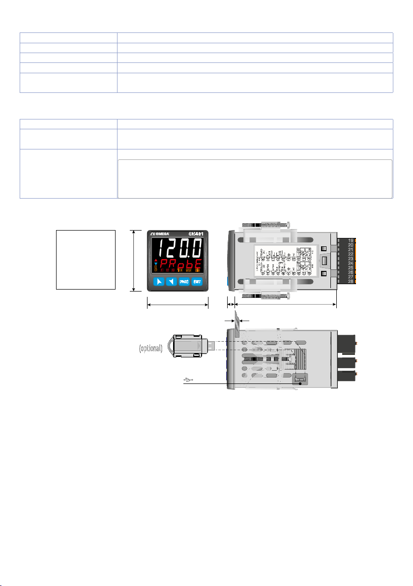
5 Dimensions and Installation
A2A1 A3
TUN
MAN
FNC SET
CN401
REM
Dima di foratura
46 x 46 mm
Frontal panel
cut-out
T
rou de panneau
48 mm
C1
C2
19
20
21
22
23
24
25
26
27
28
48 mm
Spessore suggerito / Suggested thickness / É
paisseur suggérée
8
2 ÷ 6 mm
80 mm
DP-USB-CARD
(optional)
USB
6 Electrical wirings
This controller has been designed and manufactured in conformity to Low Voltage Directive 2006/95/
EC, 2014/35/EU (LVD) and EMC Directive 2004/108/EC, 2014/30/EU (EMC). For installation in industrial
environments please observe following safety guidelines:
• Separate control line from power wires.
• Avoid proximity of remote control switches, electromagnetic contactors, powerful engines.
• Avoid proximity of power groups, especially those with phase control.
• It is strongly recommended to install adequate mains filter on power supply of the machine where
the controller is installed, particularly if supplied 230Vac.
The controller is designed and conceived to be incorporated into other machines, therefore CE
marking on the controller does not exempt the manufacturer of machines from safety and conformity
requirements applying to the machine itself.
• Wiring of pins 1...8 on CN401-11xxx: use crimped tube terminals or flexible/rigid copper wire with
diameter 0.2 to 2.5 mm2 (min. AWG28, max. AWG12, operating temperature: min. 70°C). Cable
stripping lenght 7 to 8 mm.
8 - CN40x - User manual
Page 9
• Wiring of pins 9...19 on CN401-11xxx: use crimped tube terminals or flexible/rigid copper wire with
Q1
Q2
Q3
SUPPLY
+
1
2
1
2
1
2
diameter 0.2 to 1.5 mm2 (min. AWG28, max. AWG14, operating temperature: min. 70°C). Cable
stripping lenght 6 to 7 mm.
• Wiring of pins 1...8 on CN402-111x: use crimped tube terminals or flexible/rigid copper wire with
diameter 0.2 to 2.5 mm2 (min. AWG26, max. AWG12, operating temperature: min. 70°C). Cable
stripping lenght 10 to 11 mm.
• Wiring of pins 9...28 on CN402-111x: use crimped tube terminals or flexible/rigid copper wire
with diameter 0.5 to 1 mm2 (min. AWG24, max. AWG16, operating temperature: min. 70°C). Cable
stripping lenght 7 to 8 mm.
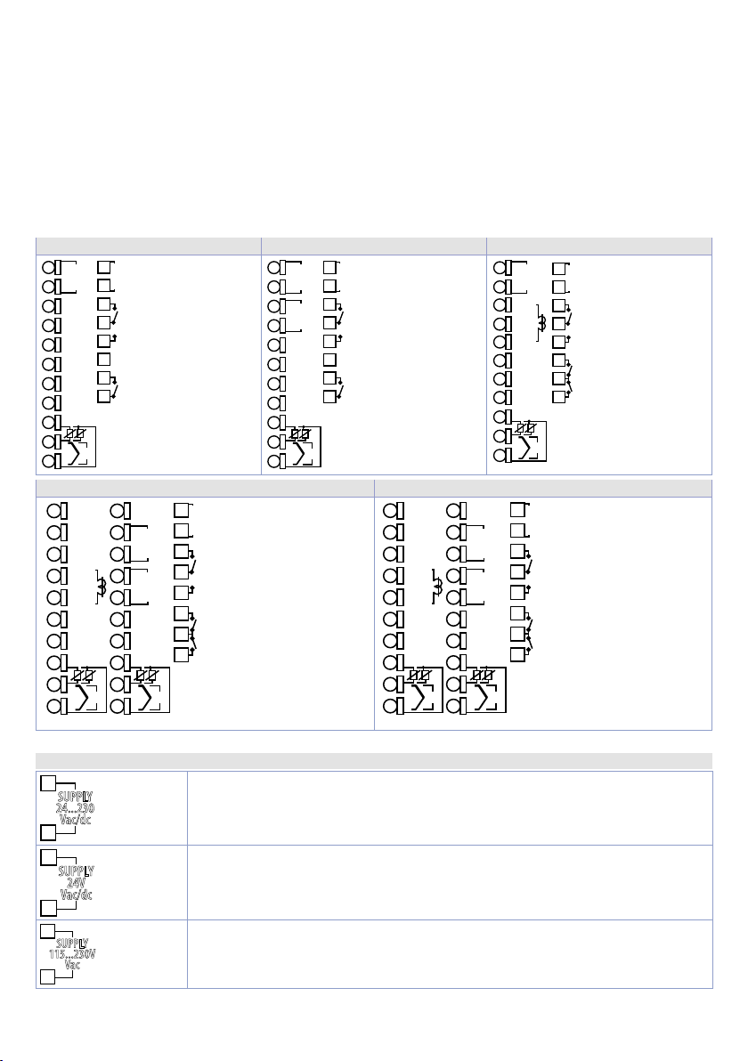
6.1 Wiring diagram
CN401-11445 CN401-11445-C4 CN 401-1114 45
+
9
AO1
V/mA
10
DO2
11
(PNP)
DO1
12
(PNP)
DI2
13
(PNP)
DI1
14
(PNP)
0V
15
+V
16
PTC
NTC
17
18
+
TC
19
CN 402-1114 455 -C4 -DC CN 402-1114 455 -C4
RS485+
19
DI/O1
20
(PNP)
DI/O2
21
(PNP)
22
(PNP)
23
(PNP)
0V 0V
24
25
+V
PTC
NTC
26
27
+
TC
28
24...230V
AC/DC
1
2
2A 230V
Resistive
3
4
5
6
2A 230V
Resistive
7
8
PT100
NI100
V/mA
(Rear view)
+
RS485-
9
(B)
DI3
DI4
+
10
11
+
12
13
CT
14
15
+V
PT100
PTC
NI100
NTC
16
V/mA
17
+
TC
18
+
AI1 AI2
SUPPLY
Q1
Q2
(A)
AO1
V/mA
AO2
V/mA
PT100
NI100
V/mA
+
24 VAC/DC
1
2
Resistive
3
4
Resistive
5
6
Resistive
7
8
(Rear view)
SUPPLY
2A 230V
2A 230V
2A 230V
24...230V
SUPPLY
PT100
NI100
V/mA
+
1
2
3
4
5
6
7
8
(Rear view)
AC/DC
Resistive
Resistive
2A 230V
2A 230V
Q1
Q2
RS485+
19
(B)
DI/O1
20
(PNP)
DI/O2
21
(PNP)
DI3
22
(PNP)
DI4
23
(PNP)
0V 0V
24
25
+V
PTC
NTC
26
27
+
TC
28
AI1 AI2
PT100
NI100
V/mA
9
AO1
V/mA
10
DO2
11
(PNP)
DO1
12
(PNP)
DI2
13
(PNP)
DI1
14
(PNP)
0V
15
+V
16
PTC
PT100
NTC
NI100
17
V/mA
18
+
TC
19
RS485-
(A)
+
AO1
V/mA
+
AO2
V/mA
+V
PTC
PT100
NTC
NI100
V/mA
+
TC
1
2
3
4
5
6
7
8
(Rear view)
+
9
10
11
12
13
CT
14
15
16
17
18
+
+
9
AO1
V/mA
10
+
11
RS485
12
DI/O2
13
(PNP)
DI/O1
14
(PNP)
0V
15
+V
16
PTC
NTC
17
18
+
TC
19
Q1
Q2
Q3
CT
+
115...230
VAC
Resistive
2A 230V
Resistive
2A 230V
Resistive
2A 230V
1
2
3
4
5
6
7
8
(Rear view)
SUPPLY
Q1
Q2
Q3
24...230V
AC/DC
Resistive
2A 230V
Resistive
2A 230V
Resistive
2A 230V
6.1.a Power Supply
SUPPLY
24...230
Vac/dc
SUPPLY
24V
Vac/dc
SUPPLY
115...230V
Vac
For CN4 01-11445, C N4 01-11445 -C4 an d CN 401-111445
Switching power supply 24..230 VAC/VDC ±15% 50/60 Hz - 6 Watt/VA.
Galvanic insulation (on all versions).
For CN4 02-1114 45 5- C4 -D C
Switching power supply 24 VAC/VDC ±15% 50/60 Hz - 6 Watt/VA.
Galvanic insulation.
For CN4 02-1114 45 5- C4
Switching power supply 115..230 VAC ±15% 50/60 Hz - 6 Watt/VA.
Galvanic insulation.
User manual - CN40x- 9
Page 10
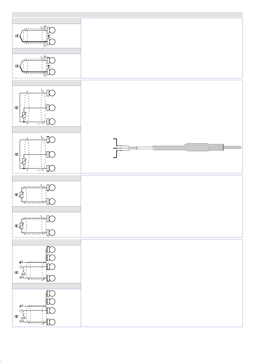
6.1.b Analogue Input AI1
Shield/Schermo
Shield/Schermo
RED/ROSSO
Shield/Schermo
Red
Shield/Schermo
Red
Shield/Schermo
Shield/Schermo
27
Shield/Schermo
16
Shield/Schermo
25
CN401-11445/-C4 and CN401-111445
AI1
TC
18
19
For thermocouples K, S, R, J, T, E, N, B.
• Comply with polarity
• For possible extensions, use compensated cable and terminals
CN 402-111x
AI1
TC
28
• When shielded cable is used, it should be grounded at one side
27
CN401-11445/-C4 and CN401-111445
Rosso
Red
Bianco
AI1
White
PT/NI100
Rosso
19
For thermoresistances PT100, Ni100.
• For the three-wire connection use wires with the same section.
18
17
• For the two-wire connection short-circuit terminals 17 and 19
• When shielded cable is used, it should be grounded at one side
CN 402-111x
Rosso
Red
Bianco
AI1
White
PT/NI100
Rosso
28
27
26
CN401-11445/-C4 and CN401-111445
17
AI1
CN 402-111x
AI1
PTC/NTC
18
For thermoresistances NTC, PTC, PT500, PT1000 and linear
potentiometers.
When shielded cable is used, it should be grounded at one side only
26
PTC/NTC
to avoid ground loop currents.
suitable for the thermocouples used (compensated).
only.
(version CN401-11x and CN401-111445) or 26 and 28.
only.
RED/ROSSO
WHITE/BIANCO
CN401-11445/-C4 and CN401-111445
+V
V
AI1
mA
18
19
CN 402-111x
+V
V
AI1
mA
10 - CN40x - User manual
27
28
For linear signals in Volt and mA
• Comply with polarity
• When shielded cable is used, it should be grounded at one side
only to avoid ground loop currents.
• It’s possible to select +V at 12Vdc or 24Vdc, by configuring
parameter 282
V.out (GROUP R - di SP. - Display and interface).
Page 11
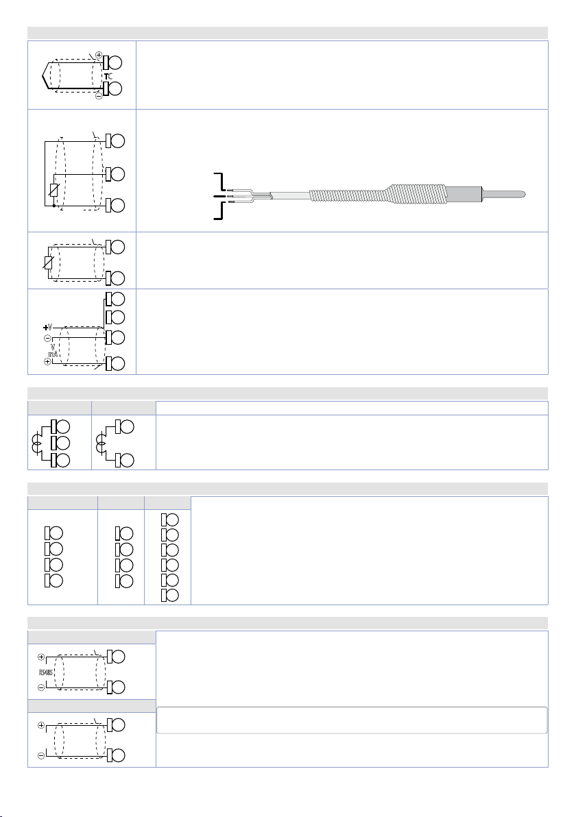
6.1.c Analogue Input AI2 (only CN402-111x)
Shield/Schermo
Red
Shield/Schermo
17
Shield/Schermo
15
13
DI2
16
DI/O2
Shield/Schermo
(A)
(A)
Shield/Schermo
Shield/Schermo
AI2
For thermocouples K, S, R, J, T, E, N, B.
• Comply with polarity
18
TC
• For possible extensions, use compensated cable and terminals suitable for
17
the thermocouples used (compensated).
• When shielded cable is used, it should be grounded at one side only.
For thermoresistances PT100, Ni100.
Rosso
Red
Bianco
AI2
White
PT/NI100
Rosso
AI2
• For the three-wire connection use wires with the same section.
18
• For the two-wire connection short-circuit terminals 16 and 18.
• When shielded cable is used, it should be grounded at one side only.
17
16
16
PTC/NTC
RED/ROSSO
WHITE/BIANCO
RED/ROSSO
For thermoresistances NTC, PTC, PT500, PT1000 and linear potentiometers.
When shielded cable is used, it should be grounded at one side only to avoid
ground loop currents.
For linear signals in Volt and mA
• Comply with polarity
+V
V
AI2
mA
• When shielded cable is used, it should be grounded at one side only to
17
avoid ground loop currents.
• To power the sensor connected to AI2 through +V (terminal 15), short-circu-
18
it terminals 14 and 17.
6.1.d CT input (only on CN401-111445 and CN402-x)
CN 401-1114 45 CN402-x
11
C.T.
C.T.
13
To enable CT input, modify parameter 287 ct F.
22
• Input for 50 mA amperometric transformer.
• Sampling time 100 ms.
23
• Configurable by parameters.
6.1.e Digital inputs
-11445 / -1114 45 -1144 5- C4 CN402-x
(PNP)
(PNP)
DI/O1
(PNP)
DI/O2
13
DI1
14
0V
15
+V
(PNP)
DI/O1
(PNP)
+V
0V
(PNP)
DI3
14
(PNP)
DI4
(PNP)
15
0V
16
+V
Digital inputs can be enabled by parameters.
20
21
Close pin
22
23
It is possible to put in parallel the digital inputs of different devices
24
joining together the 0V pins (15).
25
“DIx”
on pin
“+V ”
to enable digital input.
6.1.f Serial inputs (only CN401-11445-C4, CN402-1114455-C4 / -DC)
CN401-11445-C4
CN 402-111x
(B)
RS485
(B)
RS485
11
Modbus RS485 communication.
12
RTU Slave with galvanic insulation.
It is recommended to use the twisted and shielded cable for communica-
19
tions.
9
User manual - CN40x- 11
Page 12
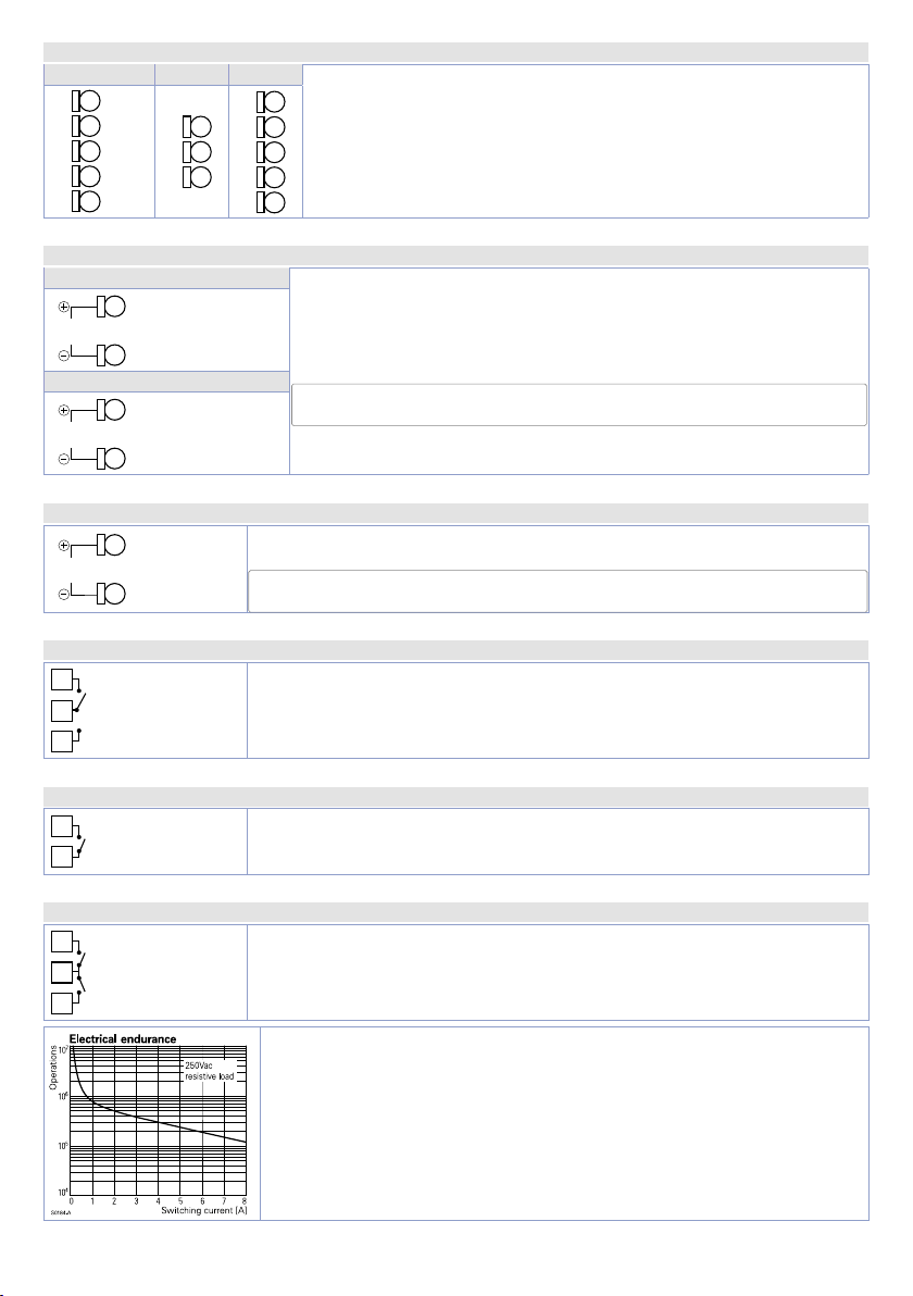
6.1.g Digital outputs
DI/O2
(PNP)
DI/O1
(PNP)
15
20
DI/O1
(PNP)
DI/O2
(PNP)
10
8
-11445 / -1114 45 -1144 5- C4 CN402-x
DO2
11
(PNP)
(PNP)
DO1
12
13
14
0V
0V
15
0V
Digital output PNP (including SSR) for command or alarm.
21
Range 12 VDC/25 mA or 24 VDC/15mA selectable by parameter 282
v.out.
24
6.1.h Analogue output AO1
CN401-11445/-C4 and CN401-111445
9
AO1
V/mA
CN 402-111x
AO1
V/mA
10
Linear output in mA or V (galvanically isolated) configurable as
command, alarm or retransmission of process-setpoint.
The selection mA or Volt for the linear output depends on the
parameters configuration.
11
6.1.i Analogue output AO2 (only CN402-x)
Linear output in mA or V (galvanically isolated) configurable as command,
alarm or retransmission of process-setpoint.
The selection mA or Volt for the linear output depends on the parameters
configuration.
AO2
V/mA
12
13
6.1.j Relay output Q1
3
Q1
2A 230V
4
Resistive
5
Capacity 2 A / 250 VAC for resistive loads.
See chart below.
6.1.k Relay output Q2 (only CN401-11445/-C4)
Q2
7
2A 230V
Resistive
Capacity 2 A / 250 VAC for resistive loads.
See chart below.
6.1.l Relays output Q2 - Q3 (only on CN401-111445 and CN402-x)
6
7
8
12 - CN40x - User manual
Q2
2A 230V
Resistive
Q3
Capacity 2 A / 250 VAC for resistive loads.
See chart below.
Electrical endurance Q1, Q2 e Q3:
2 A, 250 VAC, resistive loads, 10
20/2 A, 250 VAC, cosφ = 0.3, 10
5
operations.
5
operations.
Page 13
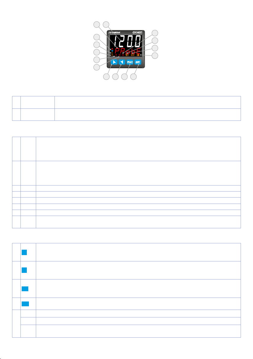
7 Display and Key Functions
1
2
15
3
4
5
6
11 12 13 14
CN401
C1
A2A1 A3
C2
TUN
MAN
FNC SET
REM
7
8
9
10
7.1 Numeric Indicators (Display)
1
2
123 .4
PRo b e
Normally displays the process. During the configuration phase, it displays the
parameter being inserted.
Normally displays the setpoint. During the configuration phase, it displays the
parameter value being inserted.
7. 2 Meaning of Status Lights (Led)
ON when the command output 1 is active. In versions with single analog input, it is ON
3 C1
4 C2
5 A1 ON when alarm 1 is active.
6 A2 ON when alarm 2 is active.
7 A3 ON when alarm 3 is active.
8 TUN ON when the controller is executing an auto-tuning cycle.
9 MAN ON when "Manual" function is active.
10 REM
when the valve is opening. In the versions with two analog inputs, in case of command
1 on the motorized valve, it is permanently ON when the valve is opening and flashing
during the closing phase.
ON when the command output 2 is active. In versions with single analog input, it is ON
when the valve is opening. In the versions with two analog inputs, in case of command
2 on the motorized valve, it is permanently ON when the valve is opening and flashing
during the closing phase.
ON when the controller communicates through serial. Flashes when the remote setpoint
is enabled.
7. 3 Keys
• Increases the main setpoint.
11
12
13
14
15
• During configuration allows to scroll the parameters or the groups of parameters.
• Increases the setpoints.
• Decreases the main setpoint.
• During configuration allows to scroll the parameters or the groups of parameters.
• Decreases the setpoints.
• Allows to visualize command and alarm setpoints.
SET
• During configuration allows to enter the parameter to be modified and confirms the
variation.
• Allows to enter the Tuning launch function, automatic/manual selection.
FNC
• During configuration works as exit key (ESCAPE).
• ON during the rising phase of the pre-programmed cycle;
c
• ON during the falling phase of the pre-programmed cycle;
d
c
• Both ON during parameter modification, when this is not a default value.
d
User manual - CN40x- 13
Page 14
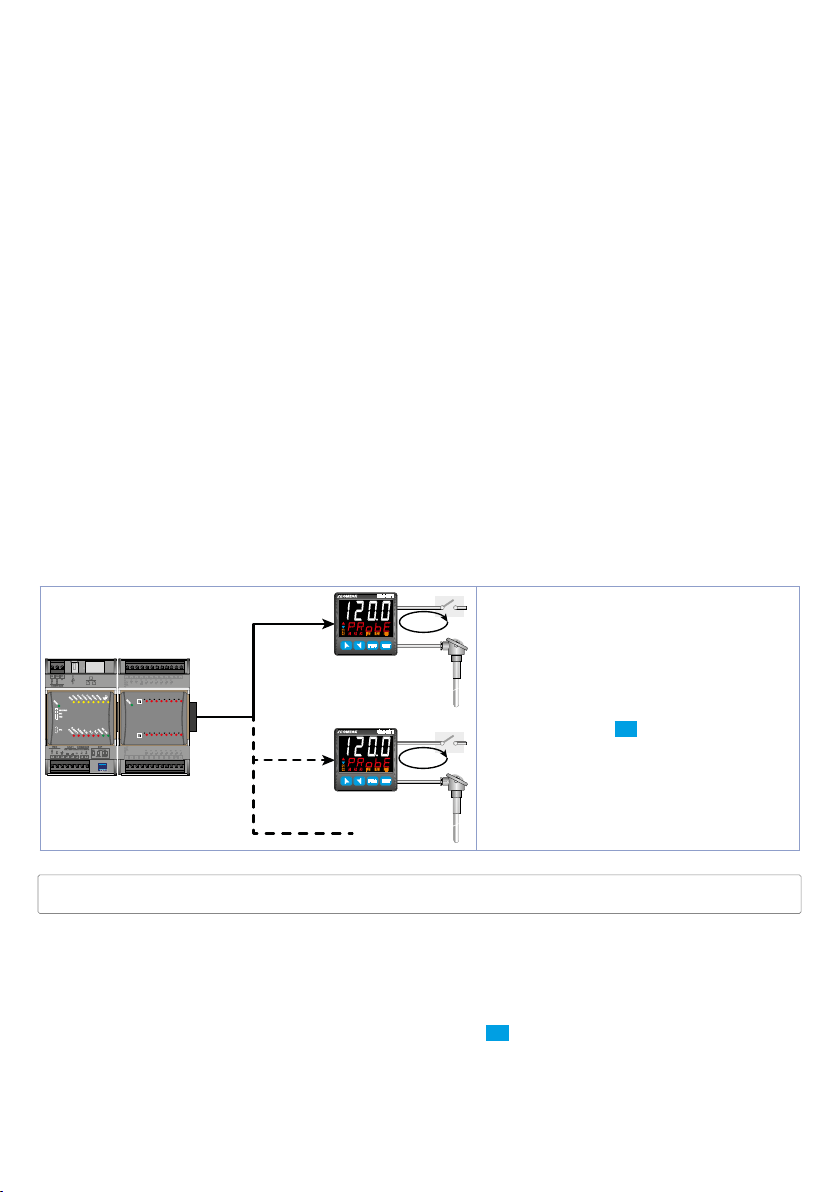
8 Dual input mode
Each model is provided with two analogue inputs: it is possible to do mathematic operations between
2 measured process values, correlating obtained result to the command or alarm outputs, or to give
a process value as remote setpoint. It is also possible to use the controller for 2 independent control
loops.
8.1 Selection of process value related to the command
output and to the alarms
When second analogue input is enabled (par.18 sen .2 other than dis A b .) it is possible to choose the
process value to be related to command output, to alarms and to retransmission.
Following options are available:
•
A .i n .1 : Value read by input AI1;
•
A.i n . 2: Value read by input AI2;
•
mea n: Mean between inputs AI1 and AI2;
•
di f f.: Difference between inputs: AI1-AI2;
•
a b . di F: Difference between inputs as absolute value: AI1-AI2;
• Command 1 process must be selected on parameter 36
c . P r .1
• Command 2 process must be selected on parameter 55 c.Pr.2
• The process related to the alarms must be selected on par. 124 a .1 . p r . for the alarm 1, on par. 142
a . 2. p r. for the alarm 2, on par. 160 a . 3. p r. for the alarm 3, and on par. 178 a .4 . p r. for the alarm 4, on par.
196
a .5. p r. for the alarm 5 and on par. 214 a . 6. p r. for the alarm 6.
• The value to be retransmitted must be selected on par. 299
r t m .1 and/or on par. 308 rtm . 2.
It is possible to choose what to visualize on display 2 selecting par. 278 ui. d .2.
8.2 Remote setpoint by analogue input
It is possible to enable remote setpoint function setting enab . or en . tst. on par. 56 rem .s.
Remote
Setpoint
PLC OUTPUT
CN3
CN1
USB1
131415 161718 19 20
21 222324
AI1
AI0
L+0
QI.1
QI.2
QI.0
QI.3
QI.5
QI.4
QI.7
QI.6
(0V)
AGND
.2
.6.7.3
.0
.4
.5
.1
+0
+1
(0V)
AGND
AQ.0
AQ.1
CN2
1 234
DP1
4...20mA
0...10V
.3
.7
.6
.0
.5
.1
.4
.2
QI.0
QI.1
QI.7
QI.6
QI.2
QI.5
QI.4
QI.3
L+1
5
7 8 9
6
10
12
AI2
Remote
Setpoint
AI2
CN401
OUT
C1
C2
Control loop
A2A1 A3
TUN
MAN
REM
FNC SET
Probe
AI1
The command setpoint is read on the
second analog input AI2: on par. 55
set
A.i n . 2. The inputs reversal is possible
by setting
Selecting
A .i n .1 on par. 55 c. p r.2.
en . tst. on par. 56 rem .s. it is
c. p r. 2
possible to switch from remote to local
CN401
OUT
C1
C2
Control loop
A2A1 A3
TUN
MAN
REM
FNC SET
Probe
AI1
setpoint pressing SET for 1 second.
The selection is stored even after the
subsequent device restarts.
In remote setpoint mode the led REM is
ON, it flashes when switching to local
setpoint mode.
The decimal point setting parameter for the image input (or remote setpoint) is locked and modifies
automatically when the command input decimal point is changed.
8.3 Remote setpoint by serial input
It is possible to enable remote setpoint function selecting en.ser. or en .s e. t. on par. 56 rem .s . The
remote setpoint must be written on the word modbus 1249 for the command 1 and 1250 for the
command 2 (with tenth of degree if the command process is a temperature sensor).
It is possible to switch from remote to local sepoint pressing SET for 1 second. In remote setpoint mode
the led REM is ON (if there is serial communication), it flashes when switching to local setpoint mode.
At restarting the controller keeps set in remote setpoint mode (the setpoint value is initialized to 0).
14 - CN40x - User manual
Page 15

9 Controller Functions
9.1 Modification of main and alarm setpoint value
Setpoint value can be modified from keyboard as follows:
Press Display Do
1
2
3
Value on display 2 changes.
Visualizes the other setpoints on display 1.
SET
Display 2 shows the setpoint type.
Value on display 1 changes.
Increases or decreases the main setpoint
value.
Increases or decreases the alarm setpoint
value.
9.2 Automatic Tune
Automatic tuning procedure allows a precise regulation without delving into the PID regulation
algorithm. Selecting Auto on par. 73
regulation loop 2), the controller analyzes the proces oscillations and optimizes the PID parameters.
Led TUN flashes.
If the PID parameters are not yet selected, at the device switch-on, it is automatically launched the
manual Tuning procedure described into the next paragraph.
t u n .1 (for the regulation loop 1), or on par. 98 tu n.2 (for the
9.3 Manual Tune
Manual procedure allows the user greater flexibility to decide when to update PID algorithm
parameters. During the manual tuning, the device generates a step to analyze the system inertia to be
regulated and, according to the collected data, modifies PID parameters.
After selecting
• Running Tuning by keyboard:
Press FNC until display 2 shows tunE with display 1 on dis. and then press SET: display 1 shows Enab.
Led TUN switches ON and the procedure starts.
• Running Tuning by digital input:
Select t
of digital input (commutation on front panel) led TUN led switches on and at second activation
switches off.
• Running Tuning by serial input:
Write 1 on word modbus 1216 (command 1) or 1217 (command 2): led TUN switches ON and the
procedure starts. Write 0 to stop the tuning.
Man u. on par. 73 t u n .1 , or on par. 98 tu n.2, the procedure can be activated in three ways:
unE on par. 231 d . i .1 . F . (or on par. 239 d.i.2.F., par. 247 d . i . 3. F. , par. 255 d .i .4 .F.). At first activation
To avoid an overshoot, the treshold where the controller calculates new PID parameters is determined
by this operation:
Tune threshold = Setpoint Ex.: if the sepoint is 100.0∞C and the Par.32
is (100.0 - 20.0) = 80.0∞C.
For a greater precision on PID parameters calculation it is suggested to start the manual tuning
procedure when the process deviates from the setpoint.
“Set Deviation Tune”
s.d.t.1 is 20.0∞C the threshold to calculate PID parameters
(par. 74 s.d.t.1 or par. 99 s.d.t.2)
9.4 Tuning once
Set once on parameter 73 t u n .1 , or on parameter 98 t un .2.
Autotuning procedure is executed only once at next CN40x restart. If the procedure doesn’t work, will
be executed at next restart.
User manual - CN40x- 15
Page 16

9.5 Synchronized tuning
Set sYNch. on parameter 73 t u n .1 or on parameter 98 tun .2.
This procedure has been conceived to calculate correct PID values on multi-zone systems, where each
temperature is influenced by the adjacent zones.
Writing on word modbus 1216 (for regulation loop 1) or 1217 (for regulation loop 2) the controller
works as follows:
Word value Action
0 Tune off
1 Command output OFF
2 Command output ON
3 Tune active
4 Tune completed: command output OFF (read only)
5 Tune not available: softstart function enabled (only reading)
Here below the functioning for regulation loop 1: the master switches-off or turns-on all zones (value
1 or 2 on word 1216) for a time long enough to create inertia on the system.
At this point the autotuning is launched (value 3 on word 1216). The controller executes the procedure
for the calculation of the new PID values. When the procedure ends, the controller switches off the
command output and selects the value 4 on word 1216. The master, who will always read the word
1216, will control the various zones and when all will have finished, will bring to 0 the value of word
1216: the various devices will regulate the temperature independently, with the new calculated values.
N.B. The maste r must read the Index 0x400E at leas t every 10 seconds or the controller will automatically
exit the autotuning procedure.
9.6 Digital input functions
The CN40x functions related to digital inputs, can be enabled by parameters 231 d . i .1 . F. , 239 d.i.2.F., 247
d . i . 3. F. and 255 d .i .4 .F..
•
2t.S w.: Two threshold setpoint modification: with digital input active the CN40x regulates on SET2,
otherwise reulates on SET1;
•
2t.S w .i .: Modification of 2 setpoints by digital input with impulse command;
•
3 t.S w .i .: Modification of 3 setpoints by digital input with impulse command,
•
4 t.S w .i .: Modification of 4 setpoints by digital input with impulse command,
•
st. /St.: Start / Stop of the controller by digital input with impulse command,
•
ru n.: The regulation is enabled only with digital input active,
•
HoLd: With digital input active the conversion is locked (visualization maintenance function);
•
tun e: Enables/disables the Tuning if par. 73 t u n .1 or par. 98 tu n .2 is selected as manu.;
•
au.ma.i.: If par. 48 a.ma.1. or par. 67 a.ma.2. is selected as enab. or en.sto. , with impulse command on
digital input, the CN40x switches the related regulation loop, from automatic to manual and vice
versa.
•
au.ma.c.: If par. 48 a.ma.1. or par. 67 a.ma.2. is selected as ena b. or en.sto. the CN40x switches to manual
the related regulation loop, with digital input active, otherwise the regulation is automatic.
•
Act. ty.: On the regulation loop selected for this function (par. 234 d . i .1 . r. or 242 d .i . 2. r. or 250 d .i . 3. r.
or 258
d .i .4. r. ), the CN40x execute a cooling type regulation with digital input active, otherwise the
regulation is of heating type;
•
A.i . 0: Zero tare function: brings the related analogue input to 0. The analogue input is selected on
par. 233
• M. reS.: Allows the reset of the output if manual reset is active for the alarms and for the command
outputs selected on par. 234
•
t.1.run: If timer 1 is enabled (par. 328 t m r .1 different from di sa b .), with digital input active, the timer is
switched to RUN, otherwise is kept in STOP;
•
t .1 . s . e . : If timer 1 is enabled (par. 328 t m r .1 different from di sa b .), acting on the digital input, the status
of the timer switches from STOP to RUN e vice versa;•
differnet from
•
t .1 . e n d . : If il timer 1 is enabled (par. 328 t m r .1 differnet from di s a b .), acting on the digital input, the
timer is switched to STOP;
16 - CN40x - User manual
d .i .1 . p . or 241 d .i .2. p . or 249 d .i .3. p . or 257 d . i .4. p .
d .i .1 . r . or 242 d .i .2. r. or 250 d .i . 3. r. or 258 d .i .4. r. ;
t .1 . s t a . : If il timer 1 is enabled (par. 328 t m r .1
di s a b .), acting on the digital input, the timer is switched to RUN;
Page 17

• t.2.run: If timer 2 is enabled (par. 331 t m r. 2 different from di s a b .), with digital input active, the timer
is switched to RUN, otherwise is kept in STOP;
•
t. 2. s. e.: If timer 2 is enabled (par. 331 t m r. 2 different from di s a b .), acting on the digital input, the
status of the timer switches from STOP to RUN e vice versa;
•
t. 2. st a .: If timer 2 is enabled (par. 331 t m r.2 different from di s a b .), acting on the digital input, the
timer is switched to RUN;
•
t. 2. e n d .: If timer 2 is enabled (par. 331 tm r. 2 different from di s a b .), acting on the digital input, the
timer is switched to STOP;
•
Lo . cf G.: With digital input active, the access to setpoint configuration/modification is locked;
•
reM.s . e.: If on par. 56 rem .s. it is selected ena b. or en.ser.), with digital input active the remote setpoint
is enabled, otherwise the setpoint is local. On par. 234
it is necessary to select the reference regulation loop.
d .i .1 . r . or 242 d .i .2. r. or 250 d .i . 3. r. or 258 d .i .4. r.
9.7 Automatic / Manual regulation for % output control
This function allows to switch from automatic functioning to manual command of the output
percentage.
With par. 48
two modes.
1 First selection (
showed
Press SET to visualize manu.; it’s now possible, during the process visualization, modify through the
keys
on display 2: immediately led MAN switches off and functioning backs to automatic.
2 Second selection (
• If there is a temporary power failure or after switch-off, the manual functioning as well as the
previous output percentage value will be maintained at restarting.
• If the sensor breaks during automatic functioning, the controller switches to manual mode while
maintaining the output percentage command unchanged as generated by the PID immediately
before breakage.
Ex: on an extruder the command in percentage of the resistance (load) is maintained also in case of
input sensor failure.
A . m a .1 . (for regulation loop 1) or par. 67 A. m a . 2. (for regulation loop 2) it is possible to select
ena b.) allows to eneble with FNC the writing p.--- on display 1, while on display 2 is
au tom.
and d the output percentage. To back to automatic, with the same procedure, select a utom .
c
en.sto.) enables the same functioning but with two important variants:
9.8 Heater Break Alarm on CT (current transformer - only
on CN401-111445 and CN402-x)
This function allows to measure load current to manage an alarm during a malfunctioning with power
in short circuit, always open or partial break of the charge. To enable this function set
par. 287
• Select on par. 289
• Select on par. 290
• Select on par. 291
• Select on par. 292
• It is possible to associate an alarm, selecting
It is possible to visualize on display 2 the average current, selecting AMPEr. on par. 278 vi. d .2.
Selecting 0 on par. 290
an Heater Break Alarm.
ct F. and the value of the connected transfomer, on par. 288 ct v..
Alarm intervention.
or par. 177
H.b.a.r. the regulation loop referred to the current measure and the Heater Break
H.b.a.t. the Heater Break Alarm intervention threshold in Ampere.
ocu. t. the intervention threshold in Ampere to control the overcurrent.
H.b.a.d. the delay time in seconds for the Heater Break Alarm intervention.
H.b.a. on par. 123 a L .1 . F. on par. 141 a L.2. F. or par. 159 a L. 3. F.
a L.4. F. or par. 195 a L. 5.F. or par. 213 aL.6.F.
H. b.A. t. it is possible to visualize the current consumption without generating
50 Hz or 60 Hz on
User manual - CN40x- 17
Page 18
9.9 Dual Action (Heating-Cooling)
ALARM OUTPUT (COOL)
ACTIVE
ACTIVE
SPV
PV
x = COOL
< 0
(HEAT)
COMMAND OUTPUT (HEAT)
ALARM OUTPUT (COOL)
ALARM OUTPUT (COOL)
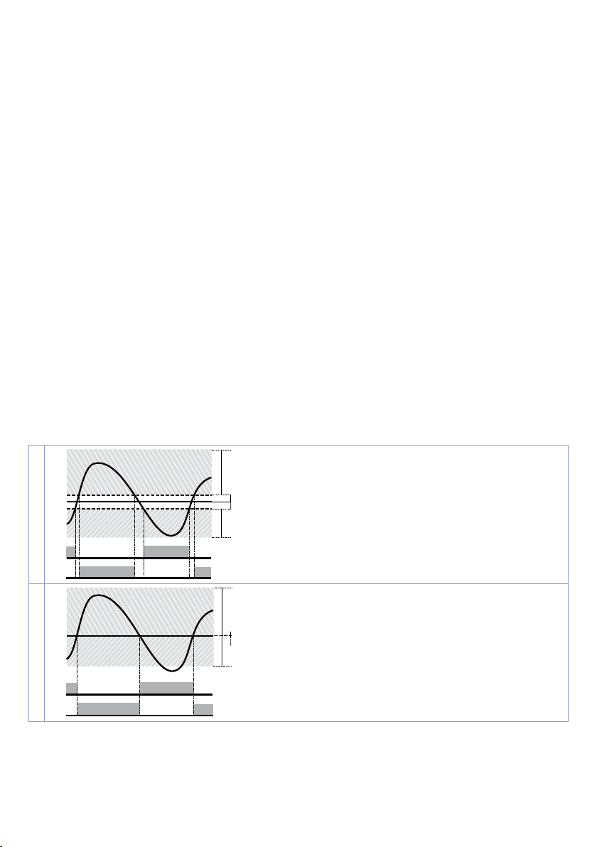
CN40x is suitable also for systems requiring a combined heating-cooling action.
The command output has to be configured as PID for Heating (Par. 38
P. b . 1 or P. b . 2 greater than 0), and one of the alarms (A L .1 . F. , AL.2. f., AL.3 . f. , AL.4 . f . , A L.5. f . or A L. 5.F. ) has to be
configured as
co o L.
The command output must be connected to the actuator responsible for heating, while the alarm will
control cooling action.
Parameters to be configured for the heating PID are:
a c . t .1 or a c. t.2 = Heat Command output action type (Heating);
P.b . 1 or p. b . 2: Heating proportional band;
i .t . 1 or i. t. 2: Integral time of heating and cooling;
d .t . 1 or d.t. 2: Derivative time of heating and cooling;
c. t. 1 or c.t. 2: Heating time cycle.
Parameters to be configured for the cooling PID related to regulation loop 1 and alarm 1 are:
A L .1 . F. = co oL. Alarm 1 selection (Cooling);
p.b.m.1: Proportional band multiplier;
o.d.b.1: Overlapping / Dead band;
c. c.t .1: Cooling time cycle.
Par.
p.b.m.1 (that renges from 1.00 to 5.00) determines the proportional band of
cooling action basing on the formula:
Proportional band for cooling action =
p. b. 1 x p.b.m.1.
This gives a proportional band for cooling which will be the same as heating band if p.b.m.1 = 1.00, or 5
times greater if
p.b.m.1 = 5.00.
Integral and derivative time are the same for both actions.
Par.
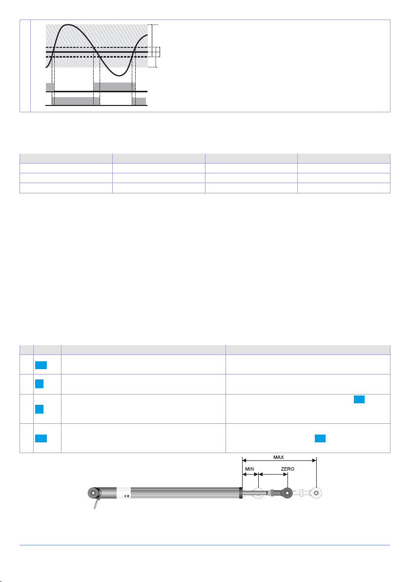
o.d.b.1 determines the percentage overlapping between the two actions. For systems in which
the heating output and cooling output must never be simultaneously active a Dead Band (
must be configured, vice versa you can configure an overlapping (
The following figure shows an example of dual action PID (heating-cooling) with
a c . t .1 or Par. 57 ac.t.2 = Heat and
o.d.b.1 ≤ 0),
o.d.b.1 > 0).
i .t . 1 = 0 e d. t. 1 = 0.
1
2
18 - CN40x - User manual
SPV
PV
SPV
PV
ACTIVE
ACTIVE
ACTIVE
ACTIVE
x = COOL
< 0
(HEAT)
COMMAND OUTPUT (HEAT)
x = COOL
= 0
(HEAT)
COMMAND OUTPUT (HEAT)
Page 19
ACTIVE
ACTIVE
SPV
PV
x = COOL
x = COOL
x = COOL
< 0
= 0
(HEAT)
(HEAT)
COMMAND OUTPUT (HEAT)
ALARM OUTPUT (COOL)
COMMAND OUTPUT (HEAT)
ALARM OUTPUT (COOL)
SPV
PV
ACTIVE
ACTIVE
SPV
3
PV
ACTIVE
ACTIVE
> 0
(HEAT)
COMMAND OUTPUT (HEAT)
ALARM OUTPUT (COOL)
Parameter c. c.T.1 has the same meaning of cycle time for heating action c.t . 1.
Parameter c o . f .1 (Cooling Fluid) pre-selects the proportional band multiplier p.b.m.1 and the cooling PID
cycle time
c o . f .1
Once parameter
c. c.T.1 according to cooling fl uid type:
Ai r
oi L
H2o
Cooling fl uid type
Air 1.00 10
Oil 1.25 4
Water 2.50 2
p.b.m.1 c. c.t.1
c o . f .1 has been selected, the parameters p.b.m.1, o.d.b.1 and c.c.T.1 can be however
modifi ed.
9.10 LATCH ON Function
For use with input po t. and with linear input (0..10 V, 0..40 mV, 0/4..20 mA) t is possible to associate start
value of the scale (par. 4
scale end (par. 5
Lt c.2 confi gured as stndr).
It is also possible to fi x the point in which the controller will display 0 (however keeping the scale
range between
L.L.i .1 / L.L.i.2 and u.L.i. 1 / u.L.i.2) using the
u.0.t.on. on par. 10 Lt c .1 or 27 Lt c. 2. Selecting u.0.t.on. the virtual zero must be reset at each switching
on; selecting
confi gure the par.
Then refer to the following table for the calibration procedure:
u.0.sto. the virtual zero will remain fi xed once calibrated. To use the LATCH ON function,
Press Display Do
Exit parameters confi guration. Display 2
FNC
visualizes writing
Store value on minimum.
Display shows
Store value on max.
Display shows
Set virtual zero. Display shows
FNC
If
“Virtual zero at start”
must be repeated at each starting.
1
2
3
4
L.L.i .1 or par. 21 L.L.i .2) to the minimum position of the sensor and value of the
u.L.i.1 or par. 22 u.L.i.2) to the maximum position of the sensor (par. 10 L t c .1 or par. 27
L t c .1 or27 Lt c.2.
La t c.
Lo w .
“virtual zero”
1
Place the sensor on minimum operating
value (corresponding to
Place sensor on maximum operating value
(corresponding to
option by selectin u.0.sto. or
L.L.i .1 / L.L.i.2)
u.L.i.1 / u.L.i.2).
To exit standard proceeding press SET.
Hi G h .
is selected, point 4
zero.
For
“virtual zero”
setting, place the sensor to
zero point.
To exit procedure press SET.
1 The tuning pro cedure starts by e xiting the confi guratio n after changing t he parameter.
User manual - CN40x- 19
Page 20
9.11 Soft-Start Function
CN40x is provided with two types of softstart selectable on parameter 264 SS. tY. (
1 First selection (
on the rising gradient set on parameter 266
parameter 269
GrAd .) enables gradient softstart. At starting the controller reaches setpoint basing
SS .G r. (
“Softstart Gradient”
SS . ti . (
“Softstart Time”
) is diff erent to 0, at starting when the time selected on par.
269 is elapsed, the controller stops to follow the gradient and reaches setpoint with the maximum
power.
2 Second selection (
the threshold under which starts the softstart (
Percentage”
PErc.) enables output percentual softstart. On par. 268 SS. tH. it is possible to set
“Softstart Threshold”
). On par. 267 SS.PE. (
) an output percentage is selectable (from 0 to 100), which controller keeps until the
process exceeds the threshold set on par. 268 or until the time in minutes set on par. 269
(
“Softstart Time”
word 2084).
If the Sof-Start function is active the automatic/manual Tuning function cannot be activated.
“Softstart Type”
).
) in Unit/hour (ex. °C/h). If
“Softstart
SS . ti .
9.12 Pre-Programmed cycle
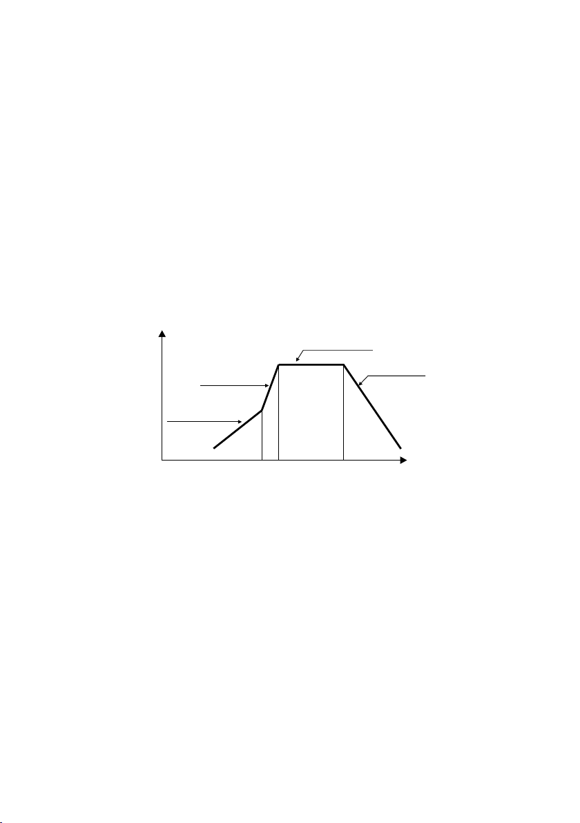
Pre-programmed cycle function activates by setting
Controller reaches setpoint 1 basing on the gradient set on parameter 266
power up to setpoint 2. When the process reaches max. power, this setpoint is maintained for the time
set on parameter 270
m a . t .i ..
At expiry, process will reach ambient temperature according to gradient entered on parameter 271
f a .Gr. , then command output will be disabled and display will visualize Sto p.
Setpoint
Rising gradient
Gradiente di salita
Setpoint 2
Max Potenza
Setpoint 1
En ab.
on parameter 263 p r. c Y. .
Maintenance time
Mantenimento
Cooling
RareddamentoMax Power
SS .G r. , then it reaches max.
Time
Cycle starts at each activation of the controller, or via digital input if it is enabled for this type of
functioning (parameters 231, 239, 247, 255 set as
st./st.
or
rUn
).
9.13 Retransmission function on analogue output
If not used as command, the analogue output can be used to retransmit process/ setpoint/ current
read by the C.T. input/ output percentage.
Select on parameter 298
value to be retransmitted and on parameter 299
r.2. tY . (“Retransmission 2 Type”) the output type.
It is possible also to select on parameters 300
value rescale limites.
20 - CN40x - User manual
r t M .1 (“Retransmission 1”) or on parameter 308 rtM.2 (“Retransmission 2”) the
r.1 . t Y . (“Retransmission 1 Type”) or on parameter 309
r.1. L.L. and 301 r.1. u . L . or 310 r.2.L. L. and 311 r.2. u .L. the input
Page 21
9.14 Timer functions
The CN40x integrates two timers that can be independent, sequential or looped together.
Timer 1 is enabled on parameter 328
EN AB.
EN.StA.
the timer starts from the keyboard or digital input (user intervention is required)
the timer starts counting when the regulator is in RUN.
t m r .1 . ; timer 2 on parameter 331 tm r.2.:
The timer time-base set in
for timer 2.
In parameter 334
other.
Si nGL.
S eQ u e.
Loo P
To change the duration of the counting time, follow the steps below:
Press Display Do
1
SET
2
To start the keyboard count follow the steps below:
Press Display Do
1
FNC
SET
2
Start/Stop of Timer is possibile also by digital input (see parameters
The alarm outputs can be associated with the timers (parameters
A. tM.1 and 333 A. tM.2 is possible to select the activation mode. The proposed solutions are as follows:
Start
End
W Ar n.
tM r. S. can be define whether the timers should be independent or related to each
The timers work independently of each other.
When timer 1 ends, timer 2 starts. The sequence is active only by starting timer 1. When
timer 2 expires, the sequence is interrupted.
When a timer ends, another starts: the sequence repeats itself cyclically.
Press until
display 1.
Digits on display 1 changes.
Press until
display 2. Display 1 shows STOP if the
timer is stopped, otherwise it shows the
remaining time.
The timer stops if active or starts counting
if in STOP.
Alarm active during timer counting
Alarm active when the timer expiry
Alarm active 5 “ before the timer expiry
mm .ss or hh.m m by changing parameters 329 t.b .t.1 for timer 1 and 332 t. b. t.2
ti m. 1 or ti m. 2 visualized on
Increase or decrease time value for the
selected timer.
ti m. 1 or ti m. 2 visualized on
d .i .1 . F ... d .i .4 .F. .)
A L .1 . F .... AL.6.F.). On parameters 330
User manual - CN40x- 21
Page 22

10 Serial communication
CN401-11445-C4, CN402-1114455-C4 / -DC is equipped with RS485 and can receive/broadcast data
via serial communication using MODBUS RTU protocol. The device can only be configured as a Slave.
This function enables the control of multiple controllers connected to a supervisory system / SCADA.
Each controller responds to a Master query only if the query contains the same address as parameter
318
sL. a d . (
The addresses permitted range from 1 to 254 and there must not be controllers with the same address
“Slave Address”
on the same line.
Address 255 can be used by the Master to communicate with all the connected equipment (broadcast
mode), while with 0 all the devices receive the command, but no response is expected.
The baud rate is selected on parameter 319
CN40x can introduce a delay (in milliseconds) of the response to the master request. This delay must
be set on parameter 321
Each parameter modification is saved by the controller in the EEPROM memory (100000 writing cycles),
while the setpoints are saved with a delay of 10 seconds after the last modification.
Changes made to words that are different from those reported in the following table can lead to
malfunction.
Modbus RTU protocol features
Selectable on parameter 319
1200bit/s 28800bit/s
Baud-rate
2400bit/s 38400bit/s
4800bit/s 57600bit/s
9600bit/s 115200bit/s
19200bit/s
Selectable on parameter 320
Format
8N1 8N2
8E1 8E2
8O1 8O2
Supported
functions
WORD READING (max 50 word) (0x03, 0x04)
SINGLE WORD WRITING (0x06)
MULTIPLE WORDS WRITING (max 50 word) (0x10)
).
se. d e. (
“Serial Delay”
bd . rt. (
).
bd . rt.
s. p. p.
“Baud Rate”
).
Here below a list of all available addresses and supported functions:
RO = Read Only R/W = Read/Write WO = Write Only
Read
Modbus
address
Description
Write
Reset
value
0 Device type RO 47x
1 Software version RO Flash
2 Boot version RO Flash
3 Slave Address RO Eepr/dip
6 Baud rate RO Eepr/dip
50 Slave address automatic learning WO 51 System code comparison for slave address automatic learning WO 500 Loading default values (write 9999) RW 0
501 Restart CN40x (write 9999) RW 0
502 Setpoint storing delay time RW 10
503 Parameters storing delay time RW 1
701 First character of the custom alarm message 1 RW “u“
...
723 Last character of the custom alarm message 1 RW 0
751 First character of the custom alarm message 2 RW “u“
...
22 - CN40x - User manual
Page 23

Read
Modbus
address
Description
Write
Reset
value
773 Last character of the custom alarm message 2 RW 0
801 First character of the custom alarm message 3 RW “u“
...
823 Last character of the custom alarm message 3 RW 0
851 First character of the custom alarm message 4 RW “u“
...
873 Last character of the custom alarm message 4 RW 0
901 First character of the custom alarm message 5 RW “u“
...
923 Last character of the custom alarm message 5 RW 0
951 First character of the custom alarm message 6 RW “u“
...
973 Last character of the custom alarm message 6 RW 0
1000 AI1 value (degrees with tenth) RO 1001 AI2 value (degrees with tenth) RO 1002 Average between AI1 and AI2 [(AI1 + AI2) /2] (degrees with tenth) RO 0
1003 Difference between AI1 and AI2 (AI1 - AI2) (degrees with tenth) RO 0
1004
Module of the difference between AI1 and AI2 (|AI1 - AI2|) (degrees with
tenth)
RO 0
1005 Sum of AI1 and AI2 (AI1 + AI2) (degrees with tenth) RO 0
1006 Real setpoint (gradient) of the regulation loop 1 RO 0
1007 Real setpoint (gradient) of the regulation loop 2 RO 0
Alarms status (0=absent, 1=present)
1008
Bit0 = Alarm 1 Bit3 = Alarm 4
Bit1 = Alarm 2 Bit4 = Alarm 5
RO 0
Bit2 = Alarm 3 Bit5 = Alarm 6
Error flags 1
Bit0 = AI1 process error (sensor 1)
Bit1 = AI2 process error (sensor 2)
Bit2 = Cold junction error
Bit3 = Safety error
Bit4 = Generic error
Bit5 = Hardware error
Bit6 = Error H.B.A. (partial ropture of the load)
1009
Bit7 = Error H.B.A. (SSR in short circuit)
RO 0
Bit8 = Overcurrent error
Bit9 = Parameters out of range error
Bit10= CPU eeprom writing error
Bit11= RFid eeprom writing error
Bit12= CPU eeprom reading error
Bit13= RFid eeprom reading error
Bit14= Eeprom calibrations bench corrupted
Bit15= Eeprom constants bench corrupted
Error flags 2
Bit0 = Missing calibrations error
1010
Bit1 = Eeprom CPU bench parameters corrupted
Bit2 = Eeprom CPU setpoint bench corrupted
RO 0
Bit3 = RFid memory not formatted
Bit4 = Error AI2 disabled
Digital inputs status (0=not active, 1=active)
1011
Bit0 = Digital inp. 1 Bit2 = Digital inp. 3
RO 0
Bit1 = Digital inp. 2 Bit3 = Digital inp. 4
User manual - CN40x- 23
Page 24

Read
Modbus
address
Description
Write
Reset
value
Outputs status (0=off, 1=on)
1012
Bit 0 = Q1 Bit 3 = DO1
Bit 1 = Q2 Bit 4 = DO2
RO 0
Bit 2 = Q3
Status led (0=OFF, 1=ON)
Bit 0 = Led UP arrow Bit 6 = Led TUN
Bit 1 = Led C1 Bit 7 = Led point time 2
1013
Bit 2 = Led C2 Bit 8 = Led MAN
RO 0
Bit 3 = Led A1 Bit 9 = Led REM
Bit 4 = Led A2 Bit 10 = Led DOWN arrow
Bit 5 = Led A3 Bit 11 = Led point time 1
Key status (0=released, 1=pressed)
1014
Bit 0 = Key UP arrow Bit 2 = Key FNC
RO 0
Bit 1 = Key DOWN arrow Bit 3 = Key SET
1015 Cold junction temperature (degrees with tenth) RO 1016 Current CT instantaneous (Ampere with tenth) RO 0
1017 Current CT average (Ampere with tenth) RO 0
1018 Current CT ON (Ampere with tenth) RO 0
1019 Current CT OFF (Ampere with tenth) RO 0
110 0 AI1 value with decimal point selection RO 1101 AI2 value with decimal point selection RO 110 2 Average between AI1 and AI2 [(AI1 + AI2) /2] with decimal point selection RO 0
110 3 Difference between AI1 and AI2 (AI1 - AI2) with decimal point selection RO 0
110 4
Module of the difference between AI1 and AI2 (|AI1 - AI2|) with decimal
point selection
RO 0
110 5 Sum of AI1 and AI2 (AI1 + AI2) with decimal point selection RO 0
110 6
110 7
Real setpoint (gradient) of the regulation loop 1 with decimal point
selection
Real setpoint (gradient) of the regulation loop 2 with decimal point
selection
RO 0
RO 0
120 0 Setpoint 1 of regulation loop 1 (degrees with tenth) R/W EEPROM
1201 Setpoint 2 of regulation loop 1 (degrees with tenth) R/W EEPROM
1202 Setpoint 3 of regulation loop 1 (degrees with tenth) R/W EEPROM
1203 Setpoint 4 of regulation loop 1 (degrees with tenth) R/W EEPROM
120 4 Setpoint 1 of regulation loop 2 (degrees with tenth) R/W EEPROM
1205 Setpoint 2 of regulation loop 2 (degrees with tenth) R/W EEPROM
120 6 Setpoint 3 of regulation loop 2 (degrees with tenth) R/W EEPROM
1207 Setpoint 4 of regulation loop 2 (degrees with tenth) R/W EEPROM
120 8
120 9
1210
1211
1212
1213
Alarm 1 setpoint (degrees with tenth)
Alarm 1 upper setpoint if Par. 123
A L .1 . F.
Alarm 2 setpoint (degrees with tenth)
Alarm 2 upper setpoint if Par. 141
A L . 2. F.
Alarm 3 setpoint (degrees with tenth)
Alarm 3 upper setpoint if Par. 159
A L .3. F.
Alarm 4 setpoint (degrees with tenth)
Alarm 4 upper setpoint if Par. 177
A L .4 . F.
Alarm 5 setpoint (degrees with tenth)
Alarm 5 upper setpoint if Par. 195
A L .5. F.
Alarm 6 setpoint (degrees with tenth)
Alarm 6 upper setpoint if Par. 213
AL.6.F.
=
=
=
=
=
=
A.ba nd
A.ba nd
A.ba nd
A.ba nd
A.ba nd
A.ba nd
R/W EEPROM
R/W EEPROM
R/W EEPROM
R/W EEPROM
R/W EEPROM
R/W EEPROM
24 - CN40x - User manual
Page 25

Modbus
address
Description
Read
Write
Start/Stop
1214
0=controller in STOP
R/W 0
1=controller in START
Hold conversion ON/OFF
1215
0=Hold conversion OFF
R/W 0
1=Hold conversion ON
Tune management for regulation loop 1
With automatic Tune (par. 73
0=autotunig function OFF
t u n .1 = Au to):
RO 0
1=autotuning ON
1216
With manual Tune (par. 73
0=autotunig function OFF
1=autotuning ON
With synchronized Tune (par. 73
t u n .1 = manu. or On cE):
R/W 0
t u n .1 = SY n cH.):
0=autotunig function OFF
1=command output OFF (forces the cooling)
2=command output ON (forces the heating)
R/W 0
3=autotuning ON
4=autotuning ended
Tune management for regulation loop 2
With automatic Tune (par. 98
0=autotunig function OFF
tu n.2 = Au to):
RO 0
1=autotuning ON
1217
With manual Tune (par. 98
0=autotunig function OFF
1=autotuning ON
With synchronized Tune (par. 98
tu n.2 = manu. or On cE):
R/W 0
tu n.2 = SY n cH.):
0=autotunig function OFF
1=command output OFF (forces the cooling)
2=command output ON (forces the heating)
R/W 0
3=autotuning ON
4=autotuning ended
1218
1219
122 0
1221
1222
Automatic/manual selection for regulation loop 1
0=automatic; 1=manual
Automatic/manual selection for regulation loop 2
0=automatic; 1=manual
Command output percentage for regulation loop 1 (0-10000)
Heating output percentage with regulation 1 in double loop (0-10000)
Command output percentage for regulation loop 1 (0-1000)
Heating output percentage with regulation 1 in double loop (0-1000)
Command output percentage for regulation loop 1 (0-100)
Heating output percentage with regulation 1 in double loop (0-100)
R/W 0
R/W 0
R/W 0
R/W 0
R/W 0
122 3 Cooling output percentage with regulation 1 in double loop (0-10000) RO 0
1224 Cooling output percentage with regulation 1 in double loop (0-1000) RO 0
122 5 Cooling output percentage with regulation 1 in double loop (0-100) RO 0
1226
1227
122 8
Command output percentage for regulation loop 2 (0-10000)
Heating output percentage with regulation 2 in double loop (0-10000)
Command output percentage for regulation loop 2 (0-1000)
Heating output percentage with regulation 2 in double loop (0-1000)
Command output percentage for regulation loop 2 (0-100)
Heating output percentage with regulation 2 in double loop (0-100)
R/W 0
R/W 0
R/W 0
Reset
value
User manual - CN40x- 25
Page 26

Read
Modbus
address
Description
Write
Reset
value
122 9 Cooling output percentage with regulation 2 in double loop (0-10000) RO 0
123 0 Cooling output percentage with regulation 2 in double loop (0-1000) RO 0
1231 Cooling output percentage with regulation 2 in double loop (0-100) RO 0
Command output manual reset for regulation loop 1: write 0 to reset the
1232
command output.
R/W 0
In reading 0=reset not allowed, 1=reset allowed
Alarms manual reset: write 0 to reset all alarms.
In reading 0=reset not allowed, 1=reset allowed
1233
Bit0 = Alarm 1 Bit3 = Alarm 4
R/W 0
Bit1 = Alarm 2 Bit4 = Alarm 5
Bit2 = Alarm 3 Bit5 = Alarm 6
Command output manual reset for regulation loop 2: write 0 to reset the
123 4
command output.
R/W 0
In reading 0=reset not allowed, 1=reset allowed
1235 Alarm 1 remote stauts (0=absent, 1=present) R/W 0
123 6 Alarm 2 remote stauts (0=absent, 1=present) R/W 0
1237 Alarm 3 remote stauts (0=absent, 1=present) R/W 0
123 8 Alarm 4 remote stauts (0=absent, 1=present) R/W 0
1239 Alarm 5 remote stauts (0=absent, 1=present) R/W 0
124 0 Alarm 6 remote stauts (0=absent, 1=present) R/W 0
1241 Value AO1 by serial (Par. 298
1242 Value AO2 by serial (Par. 308
r t M .1 = md.bus) R/W 0
rtM.2 = md.bus) R/W 0
1243 Tare di zero AI1 (1=tare; 2=reset tare) R/W 0
124 4 Tare of zero AI2 (1=tare; 2=reset tare) R/W 0
1245
124 6
1247
124 8
Tare of zero average between AI1 and AI2 [(AI1 + AI2) /2]
(1=tare; 2=reset tare)
Tare of zero difference between AI1 and AI2 (AI1 - AI2)
(1=tare; 2=reset tare)
Tare of zero module of the difference between AI1 and AI2 (|AI1 - AI2|)
(1=tare; 2=reset tare)
Tare of zero sum of AI1 and AI2 (AI1 + AI2)
(1=tare; 2=reset tare)
R/W 0
R/W 0
R/W 0
R/W 0
1249 Value of remote setpoint by command 1 serial R/W 0
125 0 Value of remote setpoint by command 2 serial R/W 0
1251 Alarm 1 lower setpoint if Par. 123
1252 Alarm 2 lower setpoint if Par. 141
1253 Alarm 3 lower setpoint if Par. 159
125 4 Alarm 4 lower setpoint if 177
1255 Alarm 5 lower setpoint if Par. 195
125 6 Alarm 6 lower setpoint if Par. 213
A L .4 . F.
A L .1 . F.
A L . 2. F.
A L .3. F.
=
A.ba nd
A L .5. F.
AL.6.F.
=
A.ba nd
(degrees with tenth) R/W EEPROM
=
A.ba nd
(degrees with tenth) R/W EEPROM
=
A.ba nd
(degrees with tenth) R/W EEPROM
(degrees with tenth) R/W EEPROM
=
A.ba nd
(degrees with tenth) R/W EEPROM
=
A.ba nd
(degrees with tenth) R/W EEPROM
130 0 Setpoint 1 of regulation loop 1, with decimal point selection R/W EEPROM
1301 Setpoint 2 of regulation loop 1, with decimal point selection R/W EEPROM
1302 Setpoint 3 of regulation loop 1, with decimal point selection R/W EEPROM
1303 Setpoint 4 of regulation loop 1, with decimal point selection R/W EEPROM
130 4 Setpoint 1 of regulation loop 2, with decimal point selection R/W EEPROM
1305 Setpoint 2 of regulation loop 2, with decimal point selection R/W EEPROM
130 6 Setpoint 3 of regulation loop 2, with decimal point selection R/W EEPROM
1307 Setpoint 4 of regulation loop 2, with decimal point selection R/W EEPROM
130 8
Alarm 1 setpoint, with decimal point selection
A L .1 . F.
=
Alarm 1 upper setpoint if Par. 123
A.ba nd
R/W EEPROM
26 - CN40x - User manual
Page 27

Read
Modbus
address
130 9
1310
1311
1312
1313
1351
1352
1353
1354
1355
1356
Description
Alarm 2 setpoint, with decimal point selection
Alarm 2 upper setpoint if Par. 141
A L . 2. F.
=
A.ba nd
Alarm 3 setpoint, with decimal point selection
Alarm 3 upper setpoint if Par. 159
A L .3. F.
=
A.ba nd
Alarm 4 setpoint, with decimal point selection
Alarm 4 upper setpoint if Par. 177
A L .4 . F.
=
A.ba nd
Alarm 5 setpoint, with decimal point selection
Alarm 5 upper setpoint if Par. 195
A L .5. F.
=
A.ba nd
Alarm 6 setpoint, with decimal point selection
Alarm 6 upper setpoint if Par. 213
Alarm 1 lower setpoint if Par. 123
AL.6.F.
A L .1 . F.
=
=
A.ba nd
A.ba nd
selection
Alarm 2 lower setpoint if Par. 141
A L . 2. F.
=
A.ba nd
selection
Alarm 3 lower setpoint if Par. 159
A L .3. F.
=
A.ba nd
selection
Alarm 4 lower setpoint if Par. 177
A L .4 . F.
=
A.ba nd
selection
Alarm 5 lower setpoint if Par. 195
A L .5. F.
=
A.ba nd
selection
Alarm 6 lower setpoint if Par. 213
AL.6.F.
=
A.ba nd
selection
, with decimal point
, with decimal point
, with decimal point
, with decimal point
, with decimal point
, with decimal point
Reset
Write
value
R/W EEPROM
R/W EEPROM
R/W EEPROM
R/W EEPROM
R/W EEPROM
R/W EEPROM
R/W EEPROM
R/W EEPROM
R/W EEPROM
R/W EEPROM
R/W EEPROM
2001 Parameter 1 R/W EEPROM
2002 Parameter 2 R/W EEPROM
... Parameter ... R/W EEPROM
2366 Parameter 366 R/W EEPROM
User manual - CN40x- 27
Page 28
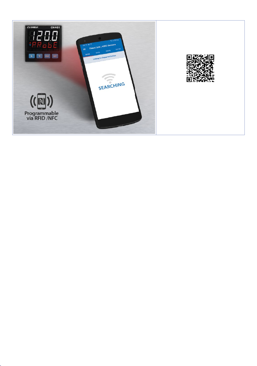
11 Reading and confi guration through NFC
Scan the Qr-Code
to download the App
on Google Play Store®
The controller CN40x is supported by the App Direct link | 400S Devices: using an ANDROID
smartphone with NFC connection it is possible to program the device without using a dedicated
equipment. The App allows to read, set and backup all parameters which are stored into the internal
memory of Omega devices.
Procedure:
• Identify the position of the NFC antenna on the smartphone (usually central, behind the back cover)
or to one of the sides in case of metal chassis. The CN40x’s antenna is placed on the frontal panel,
under the function keys.
• Make sure that the NFC sensor of the phone is enabled or that there are no metal materials between
the phone and the device (ex. aluminium cover or with magnetic stand)
• It is useful to enable the system sounds on the smartphone, as the notifi cation sound confi rms that
the device has correctly been detected.
The App interface is provided with four tabs: SCAN, DATA, WRITE, EXTRA.
Select the fi rst tab
smartphone in contact with the controller frontal panel, making sure that the phone’s antenna
matched with that of the controller.
Once detected the device, the App emits a notifi cation sounds and proceeds with the model identifi cation and the reading of the parameters.
The graphic interface shows the advancement and switches to the second tab
to move the smartphone away from the controller to make the required modifi cations more easily.
The device parameters are divided into collapsible groups and are displayed with name, current value
and reference index to the manual.
Click on a row to open the setting screen of the related parameter with the detailed view of available
options (in case of multiple choice parameters) or of the minimum/maximum/decimals limits (for
numeric parameters), included the text description (as per section n. 11 of the user manual). Once
selected the chosen value, the related row will be updated and underlined into the tab
down the line to cancel modifi cations).
To download the new confi guration on your device, select the third tab
smartphone in contact with the controller and wait for the notifi cation.
28 - CN40x - User manual
“SCAN”
to read data stored into the internal memory of the device; place the
“DATA”
. It is now possible
“WRITE”
, place again the
“DATA”
(hold
Page 29
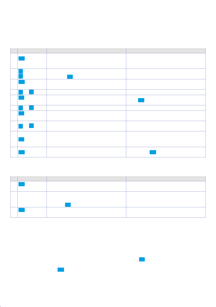
The CN40x will show a restart request, necessary to update the configuration with the new written
modifications; if it does not restart, the CN40x will continue to work with the previous configuration.
In addition to the classic operation of parameters reading->modification->writing, App Direct link |
400S Devices is provided with additional functions which can be accessed by the tab
parameters / e-mail loaded values/ restore default values.
“EXTRA”
, as save
12 Access configuration
Press Display Do
FNC
1
for 3 sec.
2
FNC
3
to confirm
4
or
SET
5
to confirm
6
or
SET
7
to confirm
8
or
SET
9
FNC
10
Display 1 shows
shows
0000 with the
1st digit flashing.
Modify flashing digit and move to next
digit with SET.
Display 1 shows the first parameters
group, display 2 shows the description.
Scroll parameters groups.
Display 1 shows the first parameter of
the group and display 2 shows its value.
Scroll parameters.
Allows parameter modification (display
2 flashes)
Increases or decreases
visualized value
Confirms and stores the new value.
If the value is different from default
values, the arrow keys light on.
Backs to parameter groups selection
(see point 3).
PASS, , while display 2
Enter password
Press FNC to exit configuration.
Introduce new data
Press again FNC to exit configuration
1234.
12.1 Loading default values
This procedure allows to restore factory settings of the device.
Press Display Do
FNC
1
for 3 sec
2
c
FNC
3
to confirm
or
d
Display 1 shows PASS,, while display 2
shows
0000 with the 1st digit flashing.
Modify the flashing digit
and move to the next one
pressing SET.
The device loads default
settings and restarts.
Enter password
9999.
12.2 Parameters list functioning
The controller CN40x integrates many features that make the configuration parameters list very
long. To make it more functional, the parameters list is dynamics and it changes as the user enables /
disables the functions. Practically, using a specific function that occupies a given input (or output), the
parameters referred to other functions of that resource are hidden to the user making the parameters
list more concise.
To simplify the reading/interpretation of the parameters, pressing SET it is possible to visualize a brief
description of the selected parameter.
Finally, keeping pressed FNC, it is possible to move from the mnemonic visualization of the parameter
to the numeric one, and vice versa. Ex. The first parameter can be displayed as
visualization) or as
Set the product parameters so that they are suitable for the system to be controlled. If they are not
suitable, unexpected operations may occasionally cause materials damage or accidents.
P. 0 01 (numeric visualization).
S E n .1 (mnemonic
User manual - CN40x- 29
Page 30

13 Table of Configuration Parameters
GROUP A -
1
SEN.1
A.i n.1
Sensor AI1
Analogue input configuration / sensor AI1 selection
tc. k
tc. s
tc. r
tc. J
Tc. T
tc. E
tc. N
tc. b
Pt1 0 0
ni1 0 0
ntc 1
Ptc
Pt50 0
Pt1k
0-1
0-5
0-1 0
0-20
4-20
0-60
Po t.
ni1 2 0
ntc 2
ntc 3
2
d .P. 1
Tc-K -260° C..1360° C. (Default)
Tc-S -40° C..1760° C
Tc-R -40° C..1760° C
Tc-J -200° C..1200° C
Tc-T -260° C..400° C
Tc-E -260° C..980° C
Tc-N -260° C..1280° C
Tc-B 100° C..1820° C
Pt100 -200° C..600° C
Ni100 -60° C..180° C
NTC 10K β3435K -40° C..125° C
PTC 1K -50° C..150° C
Pt500 -200° C..600° C
Pt1000 -200° C..600° C
0..1 V
0..5 V
0..10 V
0..20 mA
4..20 mA
0..60 mV
Potentiometer (set the value on parameter 6)
Ni120 -60 °C..240 °C
NTC 10K β3694K -40 °C..150 °C
NTC 2252 β3976K -40 °C..150 °C
Decimal Point 1
Select number of displayed decimal points for AI1
0
0.0
0.0 0
0.000
Default
1 decimal
2 decimals
3 decimals
- Analogue input 1
3
d eG r.
°C
°F
K
4
L. L.i .1
Degree
Celsius (Default)
Fahrenheit
Kelvin
Lower Linear Input AI1
AI1 lower limit only for linear signals. Ex .: with input 4..20 mA this parameter takes value ass ociated
to 4 mA. The value may be greater than the one entered on the next parameter.
-9999..+30000 [digit
5
u .L.i.1
Upper Linear Input AI1
1 p. 69
] Default: 0.
AI1 upper limit only for linear signals Ex : with input 4..20 mA this parameter takes value associated
to 20 mA.The value may be lower than the one entered on the previous parameter.
-9999..+30000 [digit
6
P. vA.1
Potentiometer Value AI1
1 p. 69
] Default:1000
Selects the value of the potentiometer connected on AI1
1..150 kohm. Default: 10kohm
30 - CN40x - User manual
Page 31

7
i . o .L.1
Linear Input over Limits AI1
If AI1 is a linear input, allows to the process to overpass the limits (parameters 4 and 5).
diS a b.
En ab.
8
o . c A .1
Disabled (Default)
Enabled
Offset Calibration AI1
AI1 Offset calibration. Value added/subtracted to the process value (ex: usually correcting the
ambient temperature value).
-9999..+9999 [digit
9
G . c a .1
Gain Calibration AI1
1 p. 69
] (degrees.tenths for temperature sensors). Default 0.
Value multiplied to the process value to calibrate the working point. Ex: to correct the range from
0..1000°C showing 0..1010°C, set the parameter to -1.0
-100.0%...+100.0%, Default: 0.0.
10
L t c .1
Latch-On AI1
Automatic setting of limits for AI1 linear input
11
c . FL.1
diS a b.
Stn rd
v. 0 .s t o .
v. 0 .t. o n .
Disabled (Default)
Standard
Virtual Zero Stored
Virtual Zero at start
Conversion Filter AI1
ADC Filter: Number of sensor readings to calculate mean that defines process value. NB: When
readings increase, control loop speed slows down. 1...15. (Default: 10)
12
c . F r .1
Conversion Frequency AI1
Sampling frequency of digital / analogue converter for AI1. Increasing the conversion speed will
slow down reading stability
(example: for fast transients, as the pressure, it is advisable to increase sampling frequency).
4.17 .H z
6.25 Hz
8.33H z
10.0Hz
12.5 H z
1 6 .7 H z
19.6 Hz
4.17 Hz (Min. conversion speed)
6.25 Hz
8.33 Hz
10.0 Hz
12.5 Hz
16.7 Hz (Default) Ideal for noises
filtering 50 / 60 Hz
19.6 Hz
33.2 Hz
39. 0Hz
50. 0Hz
6 2.0 H z
123 Hz
242 Hz
470 Hz
33.2 Hz
39.0 Hz
50.0 Hz
62.0 Hz
123 Hz
242 Hz
470 Hz (Max. speed conversion)
13
L. c.E.1
Lower Current Error 1
If AI1 is a 4-20 mA input, it determines the current value below the probe error E-05 is signaled.
2.0 MA
2.2 M A
2.4 M A
(Default)
2.6 M A
2.8 M A
3.0 M A
3.2 M A
3 .4 M A
3.6 M A
3.8 M A
14÷17 Reserved Parameters - Group A
Reserved parameters - Group A
User manual - CN40x- 31
Page 32

GROUP B -
18
SEN. 2
A.i n.2
Sensor AI2
- Analogue input 2 (only on CN-x)
Analogue input configuration / sensor AI2 selection
19
d .P. 2
diS a b.
tc. k
tc. s
tc. r
tc. J
Tc. T
tc. E
tc. N
tc. b
Pt1 0 0
ni1 0 0
ntc 1
Ptc
Pt50 0
Pt1k
0-1
0-5
0-1 0
0-20
4-20
0-60
Po t.
ni1 2 0
ntc 2
ntc 3
Disabled Disabled. (Default)
Tc-K -260° C..1360° C.
Tc-S -40° C..1760° C
Tc-R -40° C..1760° C
Tc-J -200° C..1200° C
Tc-T -260° C..400° C
Tc-E -260° C..980° C
Tc-N -260° C..1280° C
Tc-B 100° C..1820° C
Pt100 -200° C..600° C
Ni100 -60° C..180° C
NTC 10K β3435K -40 °C..125 °C
PTC 1K -50° C..150° C
Pt500 -200° C..600° C
Pt1000 -200° C..600° C
0..1 V
0..5 V
0..10 V
0..20 mA
4..20 mA
0..60 mV
PPotentiometer (set the value on parameter 23)
Ni120 -60 °C..240 °C
NTC 10K β3694K -40 °C..150 °C
NTC 2252 β3976K -40 °C..150 °C
Decimal Point 2
Select number of displayed decimal points for AI 2
0
0.0
0.0 0
0.000
Default
1 decimal
2 decimals
3 decimals
20
rEs.
Reserved
Reserved parameter.
21
L.L.i . 2
Lower Linear Input AI2
AI2 lower limit only for linear signals. E x.: with input 4..20 mA this parame ter takes value associated
to 4 mA. The value may be greater than the one entered on the next parameter.
-9999..+30000 [digit
22
u.L.i.2
Upper Linear Input AI2
1 p. 69
] Default: 0.
AI2 upper limit only for linear signals Ex: with input 4..20 mA this parameter takes value associated
to 20 mA.The value may be lower than the one entered on the previous parameter..
-9999..+30000 [digit
23
P. v A .2
Potentiometer Value AI2
1 p. 69
] Default:1000
Selects the value of the potentiometer connected on AI2
1..150 kohm. Default: 10kohm
32 - CN40x - User manual
Page 33

24
i. o.L.2
Linear Input over Limits AI2
If AI2 is a linear input, allows to the process to overpass the limits (parameters 21 and 22).
25
o. cA. 2
diS a b.
En ab.
Disabled (Default)
Enabled
Offset Calibration AI2
AI2 Offset calibration. Value added/subtracted to the process value (ex: usually correcting the
ambient temperature value).
-9999..+9999 [digit
26
G.c a.2
Gain Calibration AI2
1 p. 69
] (degrees.tenths for temperature sensors). Default 0.
Value multiplied to the process value to calibrate the working point. Ex: to correct the range from
0..1000°C showing 0..1010°C, set the parameter to -1.0
-100.0%...+100.0%, Default: 0.0.
27
Ltc .2
Latch-On AI2
Automatic setting of limits for AI2 linear input
28
c.FL.2
diS a b.
Stn rd
v. 0 .s t o .
v. 0 .t. o n
Disabled (Default)
Standard
Virtual Zero Stored
Virtual Zero at start
Conversion Filter AI2
ADC Filter: Number of sensor readings to calculate mean that defines
process value.
NB: When readings increase, control loop speed slows down.
1...15. (Default: 10)
29
c.Fr.2
Conversion Frequency AI2
Sampling frequency of digital / analogue converter for AI2.
Increasing the conversion speed will slow down reading stability
(example: for fast transients, as the pressure, it is advisable to increase sampling frequency).
4.17 .H z
6.25 Hz
8.33H z
10.0Hz
12.5 H z
1 6 .7 H z
19.6 Hz
4.17 Hz (Min. conversion speed)
6.25 Hz
8.33 Hz
10.0 Hz
12.5 Hz
16.7 Hz (Default) Ideal for filtering
noises 50 / 60 Hz
19.6 Hz
33.2 Hz
39. 0Hz
50. 0Hz
6 2.0 H z
123 Hz
242 Hz
470 Hz
33.2 Hz
39.0 Hz
50.0 Hz
62.0 Hz
123 Hz
242 Hz
470 Hz (Max. speed conversion)
L. c. E.2
30
Lower Current Error 2
If AI2 is a 4-20 mA input, it determines the current value below the probe error E-06 is signaled.
2.0 MA
2.2 M A
2.4 M A
(Default)
2.6 M A
2.8 M A
3.0 M A
3.2 M A
3 .4 M A
3.6 M A
3.8 M A
31÷34 Reserved Parameters - Group B
Reserved parameters - Group B
User manual - CN40x- 33
Page 34
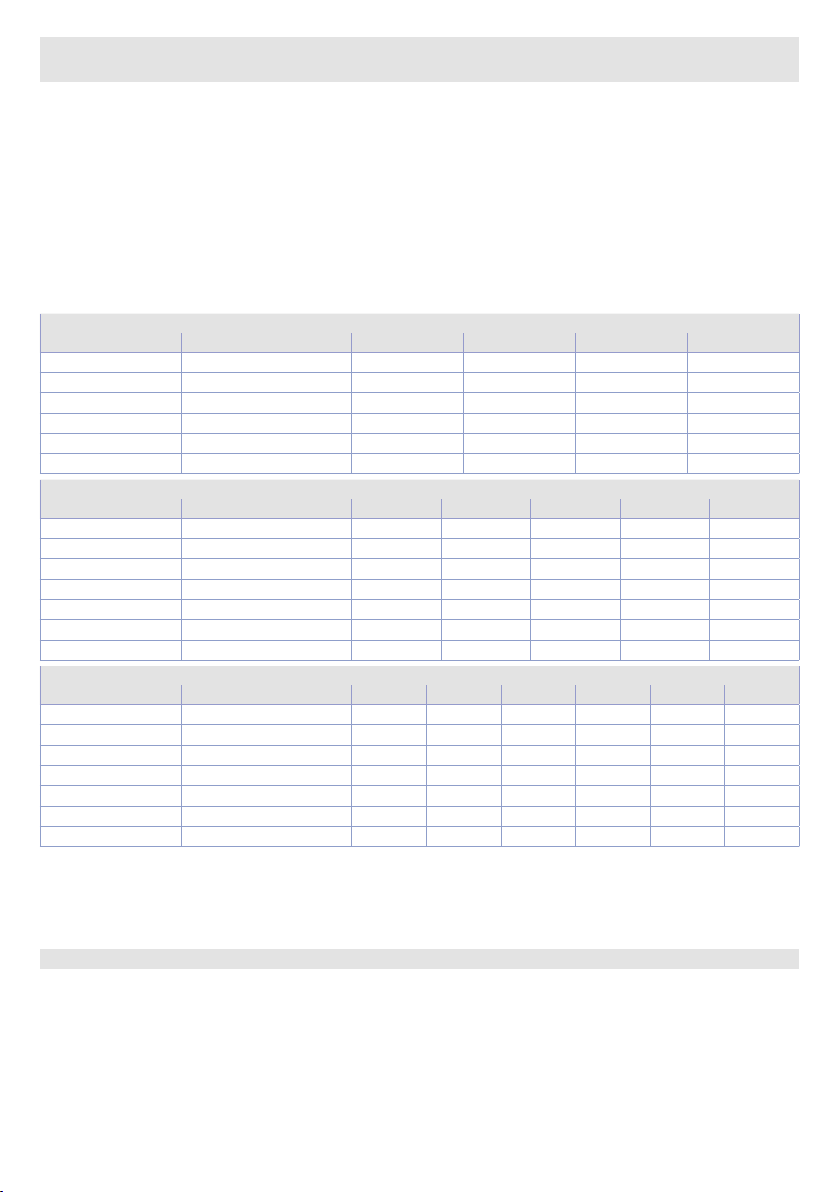
GROUP C -
35
c.ou.1
cm d.1
- Outputs and regulation Process 1
Command Output 1
Selects the command output related to the process1 and the outputs related to the alarms.
c. o 2
c. o 1
c. S S r
c. v A L.
c.0-1 0
c.4 - 2 0
0.10.S.R.
Command on relay output Q2.
Command on relay output Q1. (Default)
Command on digital output
Servo-valve command with open loop on Q1 and Q2 relays
Command 0-10 V on analogue output AO1.
Command 4-20 mA on analogue output AO1.
Command 0-10 V on analogue output AO1 with split-range function: the analogue
output sets the cooling action from 0 to 5V and heating action from 5 to 10V.
4.20.S.R.
Command 4-20 mA on analogue output AO1 with split-range function: the analogue
output sets the cooling action from 4 to 12mA and heating action from 12 to 20mA.
c.V A L.c.
Servo-valve command with open loop on Q2 and Q3 relays (not avaiable for -12xxx)
CN401-11445 and CN401-11445-C4
Command AL. 1 AL. 2 AL. 3 AL. 4
c. o 2
c. o 1
c. S S r
c. v A L.
c.0-1 0 (0.10.S.R.
c.4 - 2 0 (4.20.S.R.
Q2 Q1 DO1 DO2 AO1
Q1 Q2 DO1 DO2 AO1
DO1 Q1 Q2 DO2 AO1
Q1(open) Q2(close) DO1 DO2 AO1 -
) AO1 (0..10 V) Q1 Q2 DO1 DO2
) AO1 (4..20 mA) Q1 Q2 DO1 DO2
CN 401-1114 45
Command AL. 1 AL. 2 AL. 3 AL. 4 AL. 5
c. o 2
c. o 1
c. S S r
c. v A L.
c.0-1 0 (0.10.S.R.
c.4 - 2 0 (4.20.S.R.
c. v A L.c.
Q2 Q1 Q3 DO1 DO2 AO1
Q1 Q2 Q3 DO1 DO2 AO1
DO1 Q1 Q2 Q3 DO2 AO1
Q1(open) Q2(close) Q3 DO1 DO2 AO1 -
) AO1 (0..10 V) Q1 Q2 Q3 DO1 DO2
) AO1 (4..20 mA) Q1 Q2 Q3 DO1 DO2
Q2(open) Q3(close) Q1 DO1 DO2 AO1 -
CN 402-1114 455 -C4 -DC and CN4 02-1114 455- C4
Command AL. 1 AL. 2 AL. 3 AL. 4 AL. 5 AL. 6
c. o 2
c. o 1
c. S S r
c. v A L.
c.0-1 0 (0.10.S.R.
c.4 - 2 0 (4.20.S.R.
c. v A L.c.
Q2 Q1 Q3 DO1 DO2 AO1 AO2
Q1 Q2 Q3 DO1 DO2 AO1 AO2
DO1 Q1 Q2 Q3 DO2 AO1 AO2
Q1(open) Q2(close) Q3 DO1 DO2 AO1 AO2 -
) AO1 (0..10 V) Q1 Q2 Q3 DO1 DO2 AO2
) AO1 (4..20 mA) Q1 Q2 Q3 DO1 DO2 AO2
Q2(open) Q3(close) Q1 DO1 DO2 AO1 AO2 -
NB: if an output is used for functions other than alarms (for example retransmission or command n°
2), this resource will no longer be available as an alarm and the related group will be hidden from the
parameter list. The correspondence of the functions/outputs remains however that indicated in the
tables above.
36
c . P r.1
Command Process 1 (only on CN-x)
Selects process value related to process 1 and to command output 1.
A.in .1
A.in .2
MEAn
d i F F.
A b . d i f.
Su M
34 - CN40x - User manual
Value read on input AI1. (Default)
Value read on input AI2.
Arithmetic average of the value read on inputs AI1 and AI2 [(AI1-AI2)/2].
Difference of the values read on inputs AI1 and AI2 (AI1-AI2).
Module of the difference of the values read on inputs AI1 and AI2 (|AI1-AI2|).
Sum of values read on inputs AI1 and AI2 (AI1+AI2).
Page 35

37
rEs .
Reserved
Reserved parameter.
38
A c . t .1
Action type 1
Action type to control process 1.
HEA t
cooL
39
c . H Y .1
Hysteresis to control process 1 in ON/OFF.
-9999..+9999 [digit
40
L. L.S.1
Lower limit setpoint selectable for command setpoint 1.
-9999..+30000 [digit
41
U . L . S .1
Upper limit setpoint selectable for command setpoint 1.
-9999..+30000 [digit
42
c . r e .1
Heating (N.A.) (Default)
Cooling (N.C.)
Command Hysteresis 1
1 p. 69
] (degrees.tenths for temperature sensors). Default 0.2.
Lower Limit Setpoint 1
1 p. 69
] (degrees.tenths for temperature sensors). Default 0.
Upper Limit Setpoint 1
1 p. 69
] (degrees for temperature sensors). Default 1750.
Command Reset 1
Type of reset for command contact 1 (always automatic in P.I.D. functioning)
A. r Es.
M. r Es.
M.rEs.S.
A. rEs. t.
Automatic Reset (Default)
Manual Reset (by keyboard or by digital input)
Manual Reset Stored (keeps relay status also after an eventual power failure)
Automatic reset with timed activation. The command remains active for the time set
c. d e.1.
on the parameter 45
, even if the conditions generating it are missing. To be able
to act again, the conditions for activating the command must disappear.
c . S . e .1
43
Command State Error 1
State of contact for command 1 output in case of error.
If the command output 1 (Par. 35
open
CLose
Contact or valve open. Default
Contact or valve closed.
c.ou.1) is relay or valve:
If the command output 1 is digital output (SSR):
off
on
Digital output OFF. Default
Digital output ON.
If the command output 1 is 0-10V:
0 V
10 v
0 V. Default
10 V.
If the command output 1 is 0-20 mA or 4-20 mA:
44
c . L d .1
0 ma
4 ma
20 m a
21. 5 m a
0 mA. Default
4 mA.
20 mA.
21.5 mA.
Command Led 1
Defines led C1 state corresponding to the relevant output. If the valve command is selected, this
parameter is not managed.
o.c.
ON with open contact or SSR switched off. If command AO1, ON with output 0%, OFF if
100% and flashing between 1% and 99%.
c.c.
ON with closed contact or SSR switched on. If command AO1 ON with output 100%,
OFF if 0% and flashing between 1% and 99%. (Default)
User manual - CN40x- 35
Page 36

45
c . d e .1
Command Delay 1
Command 1 delay (only in ON / OFF functioning).
-60:00..60:00 mm:ss. Default: 00:00.
Negative: delay when turning off output.
Positive: delay when turning on output.
46
c . S . p .1
Command Setpoint Protection 1
Allows or not to modify command setpoint 1 value
47
v A . t .1
FrEE
Lock
F R.i N.
Modification allowed (Default)
Protected
Free Initialized. At start, setpoint 1 of command 1 is initialized to the value set on
i. S P.1
parameter 51
(Initial Value Setpoint 1).
Valve Time 1
Valve time related to command 1 (declared by the manufacturer of the valve)
1...300 seconds. Default: 60.
48
a.ma.1
Automatic / Manual 1
Enables the automatic/manual selection for command 1
49
i ni .S.
diS a b.
En ab.
En.S to.
Disabled (Default)
Enabled
Enabled with memory
Initial State
Choose the state of the controller when turning it on. This only works on the RS485 version or by
enabling the Start/Stop from digital input or SET button.
Start
stop
S to r e.
Start (Default)
Stop
Stored. State of Start/Stop prior to switching off.
50
S.v A.S.
State Valve Saturation
Select the valve status when the output percentage is 100%
51
i.SP.1
P ER c.
FiX E d
F R.i N.
The valve opening relay is activated for a time equal to 5% of the valve time
The valve opening relay is always active
Initial Value Setpoint 1
Free Initialized. At start, setpoint 1 of command 1 is initialized to the value set on
i. S P.1
parameter 46
(Initial Value Setpoint 1).
52÷53 Reserved Parameters - Group C
Reserved parameters - Group C
36 - CN40x - User manual
Page 37

GROUP D -
54
c.ou.2
cm d.2
Command Output 2
- Outputs and regul. Process 2 (only on CN-x)
Selects the command output related to the process 2
NB: refer to the function/output table of parameter 35
available after changing this parameter (eg: setting
enable the alarm associated with the DO2 output).
diS a b.
c. o 3
c. S S r
c. v A L.
c. 0 .-1 0
c.4 - 2 0
0.10.S.R.
Command disabled. (Default)
Command on relay output Q3
Command on digital output DO2
Servo-valve command with open loop on DO1 (open) and DO2 (close)
Command 0-10 V on analogue output AO2
Command 4-20 mA on analogue output AO2
Command 0-10 V on analogue output AO2 with split-range function: the analogue
output sets the cooling action from 0 to 5V and heating action from 5 to 10V.
4.20.S.R.
Command 4-20 mA on analogue output AO2 with split-range function: the analogue
output sets the cooling action from 4 to 12mA and heating action from 12 to 20mA.
c.o u .1
c.o u.2
to check which resources will remain
as
C.SS R
, it will no longer be possible to
c.Pr.2
55
Command Process 2
Selects process value related to process 2 and to command output 2.
56
rEM.S.
A.in .1
A.in .2
MEA n
d i F F.
A b . d i f.
SuM
Value read on input AI1. (Default)
Value read on input AI2.
Arithmetic average of the value read on inputs AI1 and AI2 [(AI1-AI2)/2].
Difference of the values read on inputs AI1 and AI2 (AI1-AI2).
Module of the difference of the values read on inputs AI1 and AI2 (|AI1-AI2|).
Sum of values read on inputs AI1 and AI2 (AI1+AI2).
Remote Setpoint
Enables remote setpoint. The control setpoint is sent by another device and is received by a
second analogue input (it is necessary to select on parameter
c. p r. 2 the selections Ai . 1 or A .i . 2.)
or through serial.
diS a b.
En ab.
Disabled. (Default)
Enables remote setpoint by process 2. Remote/local selection can be done by digital
input.
En .t St.
Remote setpoint by process 2, Remoto/local selection only by keyboard (not allowed
by digital input)
E n.S e r.
Enables remote setpoint by serial input. Remote/local selection can be done by digital
input.
E n.S e. t.
Remote setpoint by serial, Remote/local selection only by keyboard (not allowed by
digital input).
cm d. 1
The reference setpoint of command 2 is the same of command 1.
57
Ac. t.2
Action type 2
Action type to control process 2.
HEA t
cooL
58
c.HY.2
Hysteresis to control process 2 in ON/OFF.
-9999..+9999 [digit
Heating (N.A.) (Default)
Cooling (N.C.)
Command Hysteresis 2
1 p. 69
] (degrees.tenths for temperature sensors). Default 0.2.
59
L.L.S .2
Lower limit setpoint selectable for command setpoint 2.
-9999..+30000 [digit
Lower Limit Setpoint 2
1 p. 69
] (degrees for temperature sensors). Default 0.
User manual - CN40x- 37
Page 38

60
U.L.S.2
Upper limit setpoint selectable for command setpoint 2.
-9999..+30000 [digit
61
c. re.2
Upper Limit Setpoint 2
1 p. 69
] (degrees for temperature sensors). Default 1750.
Command Reset 2
Type of reset for command contact 2 (always automatic in P.I.D. functioning)
A. r Es.
M. r Es.
M.rEs.S.
A. rEs. t.
Automatic Reset (Default)
Manual Reset (by keyboard or by digital input)
Manual Reset Stored (keeps relay status also after an eventual power failure)
Automatic reset with timed activation. The command remains active for the time set
on the parameter 64 c.de.2., even if the conditions generating it are missing. To be able
to act again, the conditions for activating the command must disappear.
c.S.e.2
62
Command State Error 2
State of contact for command 2output in case of error.
If the command output 2 (Par. 54
open
CLose
Contact or valve open. Default
Contact or valve closed.
c.ou.2) is relay or valve:
If the command output 2 is digital output (SSR):
off
on
Digital output OFF. Default
Digital output ON.
If the command output 2 is 0-10V:
0 V
10 v
0 V. Default
10 V.
If the command output 2 is 0-20 mA or 4-20 mA:
63
c.Ld.2
0 ma
4 ma
20 m a
21. 5 m a
0 mA. Default
4 mA.
20 mA.
21.5 mA.
Command Led 2
Defines led C2 state corresponding to the relevant output. If the valve command is selected, this
parameter is not managed.
o.c.
ON with open contact or SSR switched off. If command AO2, ON with output 0%, OFF if
100% and flashing between 1% and 99%.
c.c.
ON with closed contact or SSR switched on. If command AO2 ON with output 100%,
OFF if 0% and flashing between 1% and 99%. (Default)
64
c. d e.2
Command Delay 2
Command 2 delay (only in ON / OFF functioning).
-60:00..60:00 mm:ss. Default: 00:00.
Negative: delay when turning off output.
Positive: delay when turning on output.
65
c.S. p. 2.
Command Setpoint Protection 2
Allows or not to modify command setpoint 2 value
66
v A. t.2
FrEE
Lock
F R.i N.
Modification allowed (Default)
Protected
Free Initialized. At start, setpoint 1 of command 2 is initialized to the value set on
i. S P. 2
parameter 70
(Initial Value Setpoint 2).
Valve Time 2
Valve time related to command 2 (declared by the manufacturer of the valve)
1...300 seconds. Default: 60.
38 - CN40x - User manual
Page 39

67
a.ma.2
Automatic / Manual 2
Enables the automatic/manual selection for command 2
68
rEs .
diS a b.
En ab.
En.S to.
Disabled (Default)
Enabled
Enabled with memory
Reserved
Reserved parameter.
69
rEs.
Reserved
Reserved parameter.
70
i.SP.2
Initial Value Setpoint 2
Determines the initial value (at start) of setpoint 1 of command 2 when
parameter 65
-9999..+30000 [digit
c.S . p. 2
(Command Setpoint Protection 2)
1 p. 69
] (degrees for temperature sensors). Default 0.
71÷72 Reserved Parameters - Group D
Reserved parameters - Group D
F R.i N.
is selected on
GROUP E -
73
t u n .1
- Autotuning and PID 1
reG.1
Tun e 1
Selects autotuning type for command 1
diS a b.
Disabled. If proportional band and integral time paramters are to selected to zero, the
regulation is ON/OFF type.. (Default)
Auto
M an u.
OncE
SY ncH.
74
s.d.t.1
Automatic (Automatic P.I.D. parameters calculation )
Manual (launch by keyboards or by digital input)
Once (P.I.D. parameters calculation only at first start)
Synchronized (Autotuning managed by serial)
Setpoint Deviation Tune 1
Selects deviation from command setpoint 1 as threshold used by
autotuning to calculate P.I.D. parameters
0-10000 [digit
75
p. b. 1
1 p. 69
] (degrees.tenths for temp. sensors). Default: 30.0.
Proportional Band 1
Proportional band or process 1 P.I.D. regulation (Process inertia).
0 ON / OFF if t.i. equal to 0 (Default)
1...10000 [digit
76
i.t. 1
1 p. 69
] (degrees.tenths for temp. sensors).
Integral Time 1
Integral time for process 1 P.I.D. regulation (process intertia duration).
0.0...2000.0 sec. (0.0 = integral disabled), Default 0.0
77
d. t. 1
Derivative Time 1
Derivative time for process 1 P.I.D. regulation (Normally ¼ of integral time).
0.0...1000.0 sec. (0.0 = derivative disabled), Default 0
78
d. b . 1
Dead band of process 1 P.I.D..
0...10000 [digit
Dead Band 1
1 p. 69
] (degrees.tenths for temp. sensors) (Default: 0)
User manual - CN40x- 39
Page 40

79
p.b.c.1
Proportional Band Centered 1
Defines if the proportional band 1 must be centered or not on the setpoint. In double loop
functioning (heating/cooling), always disabled.
diS a b.
En ab.
80
o.o.s.1
Disabled. Band under (heating) or over (cooling)(Default)
Centered band
Off Over Setpoint 1
In P.I.D. enables the command output 1 switching off, when a certain threshold is exceeded
(setpoint + Par.81)
diS a b.
En ab.
81
o.d.t.1
Disabled (Default)
Enabled
Off Deviation Threshold 1
Selects deviation from command setpoint 1, to calculate the intervention threshold of “Off Over
Setpoint 1“ function.
-9999...+9999 [digit
82
c.t . 1
Cycle Time 1
1 p. 69
] (degrees.tenths for temp. sensors) (Default: 0)
Cycle time for P.I.D. regulation of process 1 (for P.I.D. on remote control switch 15 s; for PID on SSR
2s). For valve refer to parameter 47
va.t.1
1-300 seconds (Default:15 s)
83
c o . F.1
Cooling Fluid 1
Type of refrigerant fluid for heating / cooling P.I.D. for process 1. Enable the cooling output on
parameter AL.1... AL.6.
84
P . b . M .1
Air
oiL
Wa ter
Air (Default)
Oil
Water
Proportional Band Multiplier 1
Proportional band multiplier for heating/cooling P.I.D. for process 1. Proportional band for
cooling action is given by parameter P.B. 1 multiplied for this value
1.00...5.00. Default: 1.00
85
o.d.b.1
Overlap / Dead Band 1
Dead band combination for heating / cooling P.I.D. (double action) for process 1.
-20.0%...50.0%
Negative: Dead band.
Positive: overlap. Default: 0.0%
86
c. c. t.1
Cooling Cycle Time 1
Cycle time for cooling output in heating/cooling P.I.D. mode for process 1.
1-300 seconds (Default:10 s)
87
L.L. P.1
Lower Limit Output Percentage 1
Selects min. value for command output 1 percentage.
0%...100%, Default: 0%.
88
U . L . p .1
Upper Limit Output Percentage 1
Selects max. value for command output 1 percentage.
0%...100%, Default: 100%.
40 - CN40x - User manual
Page 41

89
m . G . t .1
Max Gap Tune 1
Selects the max. process-setpoint gap beyond which the automatic tune recalculates PID
parameters of process 1.
0-10000 [digit
90
m n . p .1
1 p. 69
] (degrees.tenths for temp. sensors). Default: 2.0
Minimum Proportional Band 1
Selects the min. proportional band 1 value selectable by the automatic tune for the P.I.D.
regulation of process 1.
0-10000 [digit
91
m a . p .1
1 p. 69
] (degrees.tenths for temp. sensors). Default: 3.0
Maximum Proportional Band 1
Selects the max. proportional band 1 value selectable by the automatic tune for the P.I.D.
regulation of process 1.
0-10000 [digit
92
mn.i.1
1 p. 69
] (degrees.tenths for temp. sensors). Default: 80.0
Minimum Integral Time 1
Selects the min. integral time 1 value selectable by the automatic tune for the P.I.D. regulation
of process 1.
0.0...1000.0 seconds. Default: 30.0 s.
93
o . c . L .1
Overshoot Control Level 1
The overshoot control function prevents this event during device switching on or when the
setpoint is modified.
Setting a too low value the overshoot may not be fully absorbed, while with high values the
process could reach the setpoint more slowly.
Disab.
Lev. 1
Lev. 2
Lev. 3
Lev. 4
Lev. 5 (Default)
Lev. 6
Lev. 7
Lev. 8
Lev. 9
Lev. 10
94÷97 Reserved Parameters - Group E
Reserved parameters - Group E
GROUP F -
98
tun .2
reG.2
- Autotuning and PID 2 (only on CN-x)
Tun e 2
Selects autotuning type for command 2
diS a b.
Disabled. If proportional band and integral time paramters are to selected to zero, the
regulation is ON/OFF type. (Default)
Auto
M an u.
OncE
SY ncH.
99
s.d.t.2
Automatic (Automatic P.I.D. parameters calculation )
Manual (launch by keyboards or by digital input)
Once (P.I.D. parameters calculation only at first start)
Synchronized (Autotuning managed by serial)
Setpoint Deviation Tune 2
Selects deviation from command setpoint 2 as threshold used by
autotuning to calculate P.I.D. parameters.
0-10000 [digit
100
p. b . 2
1 p. 69
] (degrees.tenths for temp. sensors). Default: 30.0.
Proportional Band 2
Proportional band or process 2 P.I.D. regulation (Process inertia).
0 ON / OFF if t.i. equal to 0 (Default)
1...10000 [digit
101
i . t. 2
1 p. 69
] (degrees.tenths for temp. sensors).
Integral Time 2
Integral time for process 2 P.I.D. regulation (process intertia duration).
0.0...2000.0 seconds (0.0 = integral disabled), Default 0.0
User manual - CN40x- 41
Page 42

102
d . t. 2
Derivative Time 2
Derivative time for process 2 P.I.D. regulation (Normally ¼ of integral time).
0.0...1000.0 seconds (0.0 = derivative disabled), Default 0
103
d . b. 2
Dead band of process 2 P.I.D.
0...10000 [digit
104
p.b.c.2
Dead Band 2
1 p. 69
] (degrees.tenths for temp. sensors) (Default: 0)
Proportional Band Centered 2
Defines if the proportional band 2 must be centered or not on the setpoint. In double loop
functioning (heating/cooling), always disabled.
105
diS a b.
En ab.
o.o.s.2
Disabled. Band under (heating) or over (cooling) (Default)
Centered band
Off Over Setpoint 2
In P.I.D. enables the command output 2 switching off, when a certain threshold is exceeded
(setpoint + Par.106)
106
diS a b.
En ab.
o.d.t.2
Disabled (Default)
Enabled
Off Deviation Threshold 2
Selects deviation from command setpoint 2, to calculate the intervention threshold of “Off Over
Setpoint 2“ function.
-9999...+9999 [digit
107
c. t. 2
Cycle Time 2
1 p. 69
] (degrees.tenths for temp. sensors) (Default: 0)
Cycle time for P.I.D. regulation of process 2 (for P.I.D. on remote control switch 15 s; for PID on SSR
2s). For valve refer to parameter 66
va.t.2
1-300 seconds (Default:15 s)
108
co .F.2
Cooling Fluid 2
Type of refrigerant fluid for heating / cooling P.I.D. for process 2. Enable the cooling output on
parameter AL.1... AL.6.
109
Air
P. b.M.2
Air (Default)
oiL
Oil
Proportional Band Multiplier 2
Wa ter
Water
Proportional band multiplier for heating/cooling P.I.D. for process 2. Proportional band for
cooling action is given by parameter P.B. 2 multiplied for this value.
1.00..5.00. Default: 1.00
110
o.d.b.2
Overlap / Dead Band 2
Dead band combination for heating / cooling P.I.D. (double action) for process 2. -20.0..50.0%
Negative: Dead band. Positive: overlap. Default: 0.0%
111
c. c. t.2
Cooling Cycle Time 2
Cycle time for cooling output in heating/cooling P.I.D. mode for process 2.
1-300 seconds (Default:10 s)
112
L.L.P.2
Lower Limit Output Percentage 2
Selects min. value for command output 2 percentage.
0%...100%, Default: 0%.
113
U.L.p.2
Upper Limit Output Percentage 2
Selects max. value for command output 2 percentage.
0%...100%, Default: 100%.
42 - CN40x - User manual
Page 43

114
m .G.t.2
Max Gap Tune 2
Selects the max. process-setpoint gap beyond which the automatic tune recalculates PID
parameters of process 2.
0-10000 [digit
115
m n .p.2
1 p. 69
] (degrees.tenths for temp. sensors). Default: 2.0
Minimum Proportional Band 2
Selects the min. proportional band value selectable by the automatic tune for the P.I.D. regulation
of process 2.
0-10000 [digit
116
m a .p.2
1 p. 69
] (degrees.tenths for temp. sensors). Default: 3.0
Maximum Proportional Band 2
Selects the max. proportional band 2 value selectable by the automatic tune for the P.I.D.
regulation of process 2.
0-10000 [digit
117
mn.i.2
1 p. 69
] (degrees.tenths for temp. sensors). Default: 80.0
Minimum Integral Time 2
Selects the min. integral time 2 value selectable by the automatic tune for the P.I.D. regulation
of process 2.
0.0...1000.0 sec. Default: 30.0 sec.
118
o .c.L.2
Overshoot Control Level 2
The overshoot control function prevents this event during device switching on or when the
setpoint is modified. Setting a too low value the overshoot may not be fully absorbed, while with
high values the process could reach the setpoint more slowly.
Disab.
Lev. 1
Lev. 2
Lev. 3
Lev. 4
Lev. 5 (Default)
Lev. 6
Lev. 7
Lev. 8
Lev. 9
Lev. 10
119÷122 Reserved Parameters - Group F
Reserved parameters - Group F
GROUP G -
123
AL.1. f.
Alarm 1 selection.
diS a b.
A b . u p. A .
Ab.Lo.a.
bAnd
u p. d e v.
L o . d e v.
Ab.c.u.A.
A b.c.L.A.
run
cooL
P r b. er.
t M r.1
t M r. 2
t M r.1. 2
rEM.
d.i. 1
d.i. 2
d.i. 3
d.i. 4
H.b.A.
AL. 1
- ALARM 1
Alarm 1 Function
Disabled (Default)
Absolute Upper Activation. Absolute referred to the process, active over
Absolute Lower Activation. Absolute referred to the process, active under
Band alarm (command setpoint ± alarm setpoint)
Upper Deviation alarm
Lower Deviation alarm
Absolute Command Upper Activation. Absolute alarm referred to the command
setpoint, active over
Absolute Command Lower Activation. Absolute alarm referred to the command
setpoint, active under
Status alarm (active in RUN/START)
Cold actuator auxiliary (Cold action in double loop)
Probe error. Alarm active in case of sensor rupture.
Related to timer 1
Related to timer 2
Related to both timers
Remote. The alarm is enabled by the word 1235
Digital Input 1. Active when digital input 1 is active.
Digital Input 2. Active when digital input 2 is active.
Digital Input 3. Active when digital input 3 is active.
Digital Input 4. Active when digital input 4 is active.
Heater Break Alarm and Overcurrent Alarm
User manual - CN40x- 43
Page 44

a.b An d
Asymmetric band alarm (command setpoint + alarm setpoint 1 H and command
setpoint - alarm setpoint 1 L).
c. a u x
Auxiliary for job distribution on the command output. It cyclically replaces the
command output for the time set on the parameter 134
parallel to the command output. It does not work in case of valve control and can only
be activated on an alarm if
124
A .1 . P r .
Alarm 1 Process (only on CN-x)
Selects the size related to alarm 1.
125
A.in .1
A.in .2
MEA n
d i F F.
A b . d i f.
SuM
A.I. r.c.
Value read on input AI1. (Default)
Value read on input AI2.
Arithmetic average of the value read on inputs AI1 and AI2 [(AI1+AI2)/2].
Difference of the values read on inputs AI1 and AI2 (AI1-AI2).
Module of the difference of the values read on inputs AI1 and AI2(|AI1-AI2|).
Sum of values read on inputs AI1 and AI2 (AI1+AI2).
Alarm 1 Reference Command (only on CN-x)
Selects alarm 1 reference command
126
cm d. 1
cm d. 2
A . I. 5 . o .
Alarm referred to command 1. (Default)
Alarm referred to command 2.
Alarm 1 State Output
Alarm 1 output contact and intervention type.
127
n. o. S t.
n.c. S t.
n.o. t H.
n.c. t H.
n.o.tH.V.
n.c.tH.V.
rEs .
(N.O. Start) Normally open, active at start (Default)
(N.C. Start) Normally closed, active at start
(N.O. Threshold) Normally open, active on reaching alarm
(N.C. Threshold) Normally closed, active on reaching alarm
(N.O. Threshold Variation) disabled after changing control setpoint
(N.C. Threshold Variation) disabled after changing control setpoint
Reserved
Reserved parameter.
A .1 . d e . . Se A.1. d e . = 0, it is activated
A .1 . d e . is different from 0.
2 p. 69
2 p. 69
3 p. 69
3 p. 69
128
a .1 . H y .
Alarm 1 hysteresis
-9999..+9999 [digit
129
A .1. L.L.
Lower limit selectable for the alarm 1 setpoint.
-9999..+30000 [digit
130
A .1 . u . L .
Upper limit selectable for the alarm 1 setpoint
-9999..+30000 [digit
131
a .1 . r e .
Alarm 1 Hysteresis
1 p. 69
] (degrees for temp. sensors). Default 0.5.
Alarm 1 Lower Limit
1 p. 69
] (degrees for temp. sensors). Default 0.
Alarm 1 Upper Limit
1 p. 69
] (degrees for temp. sensors). Default 1750.
Alarm 1 Reset
Alarm 1 contact reset type (always automatic if
A. r Es.
M. r Es.
M.rEs.S.
A. r Es. t.
Automatic reset (Default)
Manual reset (manual reset by keyboard or by digital input)
Stored manual reset (keeps the output status also after a power failure)
Automatic reset with timed activation. The alarm remains active for the time set on the
a.1. d e.
parameter 134
, even if the conditions generating it are missing. To be able to act
again, the alarm conditions must disappear.
44 - CN40x - User manual
A L .1 . F.
=
c. A u x
).
Page 45

132
A .1 . S . e .
Alarm 1 State Error
Alarm 1 output status in case of error.
133
open
CLose
A .1 . L d .
Open contact. Default
Closed contact.
Alarm 1 Led
Defines the status of the led A1 in correspondence of the relevant output
134
o.c.
c.c.
a .1 . d e .
ON with open contact or DO switched off.
ON with closed contact or DO switched on. (Default)
Alarm 1 Delay
Alarm 1 Delay.
-60:00..60:00 mm:ss (hh:mm if
A L .1 . F.
=
c. a u x
). Default: 00:00.
Negative value: delay when exit alarm status.
Positive value: delay when enter alarm status.
135
A .1 . S . p .
Alarm 1 Setpoint Protection
Allows or not to change the alarm 1 setpoint
136
FrEE
Lock
Hid E
A .1 . L b .
Editable by the user (Default)
Protected
Protected and not visualized
Alarm 1 Label
Selects the message displayed in case of alarm 1 intervention.
dis a b.
lb. 0 1
..
lb. 16
u ser. l.
Disabled. (Default) 0.
Message 1 (see table on paragraph .)
Message 16 (see table on paragraph .)
Custom message (modifiable by the user through the App or via modbus)
137÷140 Reserved Parameters - Group G
Reserved parameters - Group G
GROUP H -
141
AL. 2. f.
AL. 2
- Alarm 2
Alarm 2 Function
Alarm 2 selection.
diS a b.
A b . u p. A .
Ab.Lo.a.
bAnd
u p. d e v.
L o . d e v.
Ab.c.u.A.
Disabled (Default)
Absolute Upper Activation. Absolute referred to the process, active over
Absolute Lower Activation. Absolute referred to the process, active under
Band alarm (command setpoint ± alarm setpoint)
Upper Deviation alarm
Lower Deviation alarm
Absolute Command Upper Activation. Absolute alarm referred to the command
setpoint, active over
A b.c.L.A.
Absolute Command Lower Activation. Absolute alarm referred to the command
setpoint, active under
run
cooL
P r b. er.
t M r.1
t M r. 2
t M r.1. 2
rEM.
d.i. 1
d.i. 2
d.i. 3
Status alarm (active in RUN/START)
Cold actuator auxiliary (Cold action in double loop)
Probe error. Alarm active in case of sensor rupture.
Related to timer 1
Related to timer 2
Related to both timers
Remote. The alarm is enabled by the word 1236
Digital Input 1. Active when digital input 1 is active.
Digital Input 2. Active when digital input 2 is active.
Digital Input 3. Active when digital input 3 is active.
User manual - CN40x- 45
Page 46

d.i. 4
H.b.A.
a.b An d
Digital Input 4. Active when digital input 4 is active.
Heater Break Alarm and Overcurrent Alarm
Asymmetric band alarm (command setpoint + alarm setpoint 2 H and command
setpoint - alarm setpoint 2 L).
c. a u x
Auxiliary for job distribution on the command output. It cyclically replaces the
command output for the time set on the parameter 152
activated parallel to the command output. It does not work in case of valve control and
can only be activated on an alarm if
142
A.2.Pr.
Alarm 2 Process (only on CN-x)
Selects the size related to alarm 2.
143
A.in .1
A.in .2
MEA n
d i F F.
A b . d i f.
SuM
A.2. r. c.
Value read on input AI1. (Default)
Value read on input AI2.
Arithmetic average of the value read on inputs AI1 and AI2 [(AI1+AI2)/2].
Difference of the values read on inputs AI1 and AI2 (AI1-AI2).
Module of the difference of the values read on inputs AI1 and AI2(|AI1-AI2|).
Sum of values read on inputs AI1 and AI (AI1+AI2).
Alarm 2 Reference Command (only on CN-x)
Selects alarm 2 reference command
144
cm d. 1
cm d. 2
A. 2.5. o .
Alarm referred to command 1. (Default)
Alarm referred to command 2.
Alarm 2 State Output
Alarm 2 output contact and intervention type.
n. o. S t.
n.c. S t.
n.o. t H.
n.c. t H.
n.o.tH.V.
n.c.tH.V.
(N.O. Start) Normally open, active at start (Default)
(N.C. Start) Normally closed, active at start
(N.O. Threshold) Normally open, active on reaching alarm
(N.C. Threshold) Normally closed, active on reaching alarm
(N.O. Threshold Variation) disabled after changing control setpoint
(N.C. Threshold Variation) disabled after changing control setpoint
A. 2. d e.
is different from 0.
A. 2. d e.
2 p. 69
2 p. 69
. If
3 p. 69
3 p. 69
A. 2. d e.
= 0, it is
145
rEs .
Reserved
Reserved parameter.
146
a .2.Hy.
Alarm 2 hysteresis
-9999..+9999 [digit
147
A. 2.L. L.
Lower limit selectable for the alarm 2 setpoint.
-9999..+30000 [digit
148
A.2. u . L.
Upper limit selectable for the alarm 2 setpoint
-9999..+30000 [digit
149
a . 2. re.
Alarm 2 Hysteresis
1 p. 69
] (degrees for temp. sensors). Default 0.5.
Alarm 2 Lower Limit
1 p. 69
] (degrees for temp. sensors). Default 0.
Alarm 2 Upper Limit
1 p. 69
] (degrees for temp. sensors). Default 1750.
Alarm 2 Reset
Alarm 2 contact reset type (always automatic if
A. r Es.
M. r Es.
M.rEs.S.
A. r Es. t.
Automatic reset (Default)
Manual reset (manual reset by keyboard or by digital input)
Stored manual reset (keeps the output status also after a power failure)
Automatic reset with timed activation. The alarm remains active for the time set on the
a. 2. d e.
parameter 152
, even if the conditions generating it are missing. To be able to act
again, the alarm conditions must disappear.
46 - CN40x - User manual
A L . 2. F.
=
c. A u x
).
Page 47

150
A .2.S . e.
Alarm 2 State Error
Alarm 2 output status in case of error
If the alarm output is relay
open
Contact or open valve. Default
CLose
If the alarm output is digital (SSR):
151
off
A.2.Ld.
Digital output OFF. Default
Alarm 2 Led
on
Defines the status of the led A2 in correspondence of the relevant output.
o.c.
c.c.
152
a .2. d e.
Alarm 2 Delay. -60:00..60:00 mm:ss (hh:mm if
ON with open contact or DO switched off.
ON with closed contact or DO switched on. (Default)
Alarm 2 Delay
A L . 2. F.
=
c. a u x
Negative value: delay when exit alarm status.
Positive value: delay when enter alarm status
153
A .2. S. p.
Alarm 2 Setpoint Protection
Allows or not to change the alarm 2 setpoint
154
FrEE
Lock
Hid E
A.2.Lb.
Editable by the user (Default)
Protected
Protected and not visualized
Alarm 2 Label
Selects the message displayed in case of alarm 2 intervention.
dis a b.
lb. 0 1
..
lb. 2 0
u ser. l.
Disabled. (Default) 0.
Message 1 (see table on paragraph .)
Message 20 (see table on paragraph .)
Custom message (modifiable by the user through the App or via modbus)
Contact or closed valve.
Digital output ON.
). Default: 00:00.
155÷158 Reserved Parameters - Group H
Reserved parameters - Group H
GROUP I -
159
AL.3. f.
- Alarm 3
AL. 3
Alarm 3 Function
Alarm 3 selection.
diS a b.
A b . u p. A .
Ab.Lo.a.
bAnd
u p. d e v.
L o . d e v.
Ab.c.u.A.
Disabled (Default)
Absolute Upper Activation. Absolute referred to the process, active over
Absolute Lower Activation. Absolute referred to the process, active under
Band alarm (command setpoint ± alarm setpoint)
Upper Deviation alarm
Lower Deviation alarm
Absolute Command Upper Activation. Absolute alarm referred to the command
setpoint, active over
A b.c.L.A.
Absolute Command Lower Activation. Absolute alarm referred to the command
setpoint, active under
run
cooL
P r b. er.
t M r.1
t M r. 2
t M r.1. 2
rEM.
d.i. 1
d.i. 2
d.i. 3
Status alarm (active in RUN/START)
Cold actuator auxiliary (Cold action in double loop)
Probe error. Alarm active in case of sensor rupture.
Related to timer 1
Related to timer 2
Related to both timers
Remote. The alarm is enabled by the word 1237
Digital Input 1. Active when digital input 1 is active.
Digital Input 2. Active when digital input 2 is active.
Digital Input 3. Active when digital input 3 is active.
User manual - CN40x- 47
Page 48

d.i. 4
H.b.A.
a.b An d
Digital Input 4. Active when digital input 4 is active.
Heater Break Alarm e Overcurrent Alarm
Asymmetric band alarm (command setpoint + alarm setpoint 3 H and command
setpoint - alarm setpoint 3 L).
c. a u x
Auxiliary for job distribution on the command output. It cyclically replaces the
command output for the time set on the parameter 170
activated parallel to the command output. It does not work in case of valve control and
can only be activated on an alarm if
160
A .3.P r.
Alarm 3 Process (only on CN-x)
Selects the size related to alarm 3.
161
A.in .1
A.in .2
MEA n
d i F F.
A b . d i f.
SuM
A.3.r. c.
Value read on input AI1. (Default)
Value read on input AI2.
Arithmetic average of the value read on inputs AI1 and AI2 [(AI1+AI2)/2].
Difference of the values read on inputs AI1 and AI2 (AI1-AI2).
Module of the difference of the values read on inputs AI1 and AI2 (|AI1-AI2|).
Sum of values read on inputs AI1 and AI2 (AI1+AI2).
Alarm 3 Reference Command (only on CN-x)
Selects alarm 3 reference command
162
cm d. 1
cm d. 2
A.3.5. o .
Alarm referred to command 1. (Default)
Alarm referred to command 2.
Alarm 3 State Output
Alarm 3 output contact and intervention type..
n. o. S t.
n.c. S t.
n.o. t H.
n.c. t H.
n.o.tH.V.
n.c.tH.V.
(N.O. Start) Normally open, active at start (Default)
(N.C. Start) Normally closed, active at start
(N.O. Threshold) Normally open, active on reaching alarm
(N.C. Threshold) Normally closed, active on reaching alarm
(N.O. Threshold Variation) disabled after changing control setpoint
(N.C. Threshold Variation) disabled after changing control setpoint
A. 3. d e.
is different from 0.
2 p. 69
2 p. 69
A. 3. d e.
If
3 p. 69
3 p. 69
A. 3. d e.
= 0, it is
163
A.3.o.t.
Alarm 3 Output Type
Defines the output type if the alarm 3 is analogue.
0.1 0 v
4.2 0m a
164
a .3.Hy .
Alarm 3 hysteresis.
-9999..+9999 [digit
165
A.3.L.L
Lower limit selectable for the alarm 3 setpoint.
-9999..+30000 [digit
166
A. 3. u . L.
Upper limit selectable for the alarm 3 setpoint
-9999..+30000 [digit
167
a .3. re.
Output 0...10 V. Default
Output 4...20 mA.
Alarm 3 Hysteresis
1 p. 69
] (degrees for temp. sensors). Default 0.5.
Alarm 3 Lower Limit
1 p. 69
] (degrees for temp. sensors). Default 0.
Alarm 3 Upper Limit
1 p. 69
] (degrees for temp. sensors). Default 1750.
Alarm 3 Reset
Alarm 3 contact reset type (always automatic if
A. r Es.
M. r Es.
M.rEs.S.
A. r Es. t.
Automatic reset (Default)
Manual reset (manual reset by keyboard or by digital input)
Stored manual reset (keeps the output status also after a power failure)
Automatic reset with timed activation. The alarm remains active for the time set on the
a. 3. d e.
parameter 170
, even if the conditions generating it are missing. To be able to act
again, the alarm conditions must disappear.
48 - CN40x - User manual
A L .3. F.
=
c. A u x
).
Page 49

168
A.3.S. e.
Alarm 3 State Error
Alarm 3 output status in case of error.
If the alarm output is relay
open
Contact or open valve. Default
If the alarm output is digital (SSR):
off
Digital output OFF. Default
If the alarm output is 0-10V:
0 V
0 V. Default
If the alarm output is 0-20 mA or 4-20 mA:
0 ma
4 ma
0 mA. Default
4 mA.
CLose
on
10 v
20 m a
21. 5 m a
Contact or closed valve.
Digital output ON.
10 V.
20 mA.
21.5 mA.
169
A.3.Ld .
Alarm 3 Led
Defines the status of the led A3 in correspondence of the relevant output.
170
o.c.
c.c.
a .3.de .
ON with open contact, DO switched off or AO deactivated.
ON with closed contact, DO switched on or AO activated. (Default)
Alarm 3 Delay
Alarm 3 Delay.
-60:00..60:00 mm:ss (hh:mm if
A L .3. F.
=
c. a u x
). Default: 00:00.
Negative value: delay when exit alarm status.
Positive value: delay when enter alarm status
171
A.3.S. p.
Alarm 3 Setpoint Protection
Allows or not to change the alarm 3 setpoint.
172
FrEE
Lock
Hid E
A .3. Lb .
Editable by the user (Default)
Protected
Protected and not visualized
Alarm 3 Label
Selects the message displayed in case of alarm 3 intervention.
dis a b.
lb. 0 1
lb. 2 0
u ser. l.
Disabled. (Default) 0.
Message 1 (see table on paragraph .) ...
Message 20 (see table on paragraph .)
Custom message (modifiable by the user through the App or via modbus)
173÷176 Reserved Parameters - Group I
Reserved parameters - Group I
GROUP J -
177
A L.4 . f .
- Alarm 4
AL. 4
Alarm 4 Function
Alarm 4 selection.
diS a b.
A b . u p. A .
Ab.Lo.a.
bAnd
u p. d e v.
L o . d e v.
Ab.c.u.A.
Disabled (Default)
Absolute Upper Activation. Absolute referred to the process, active over
Absolute Lower Activation. Absolute referred to the process, active under
Band alarm (command setpoint ± alarm setpoint)
Upper Deviation alarm
Lower Deviation alarm
Absolute Command Upper Activation. Absolute alarm referred to the command
setpoint, active over
A b.c.L.A.
Absolute Command Lower Activation. Absolute alarm referred to the command
setpoint, active under.
run
cooL
P r b. er.
Status alarm (active in RUN/START)
Cold actuator auxiliary (Cold action in double loop)
Probe error. Alarm active in case of sensor rupture.
User manual - CN40x- 49
Page 50

t M r.1
t M r. 2
t M r.1. 2
rEM.
d.i. 1
d.i. 2
d.i. 3
d.i. 4
H.b.A.
a.b An d
Related to timer 1
Related to timer 2
Related to both timers
Remote. The alarm is enabled by the word 1238
Digital Input 1. Active when digital input 1 is active.
Digital Input 2. Active when digital input 2 is active.
Digital Input 3. Active when digital input 3 is active.
Digital Input 4. Active when digital input 4 is active.
Heater Break Alarm and Overcurrent Alarm
Asymmetric band alarm (command setpoint + alarm setpoint 4 H and command
setpoint - alarm setpoint 4 L).
c. a u x
Auxiliary for job distribution on the command output. It cyclically replaces the
command output for the time set on the parameter 188
activated parallel to the command output. It does not work in case of valve control and
can only be activated on an alarm if
178
A.4. Pr.
Alarm 4 Process (only on CN-x)
Selects the size related to alarm 4.
179
A.in .1
A.in .2
MEAn
d i F F.
A b . d i f.
Su M
A.4. r. c.
Value read on input AI1. (Default)
Value read on input AI2.
Arithmetic average of the value read on inputs AI1 and AI2 [(AI1+AI2)/2].
Difference of the values read on inputs AI1 and AI2 (AI1-AI2).
Module of the difference of the values read on inputs AI1 and AI2(|AI1-AI2|).
Sum of values read on inputs AI1 and AI2 (AI1+AI2).
Alarm 4 Reference Command
Selects alarm 4 reference command
180
cmd. 1
cm d. 2
A .4. 5. o .
Alarm referred to command 1. (Default)
Alarm referred to command 2.
Alarm 4 State Output
Alarm 4 output contact and intervention type.
n. o. S t.
n.c. S t.
n.o. t H.
n.c. t H.
n.o.tH.V.
n.c.tH.V.
(N.O. Start) Normally open, active at start (Default)
(N.C. Start) Normally closed, active at start
(N.O. Threshold) Normally open, active on reaching alarm
(N.C. Threshold) Normally closed, active on reaching alarm
(N.O. Threshold Variation) disabled after changing control setpoint
(N.C. Threshold Variation) disabled after changing control setpoint
A .4.d e.
is different from 0.
2 p. 69
2 p. 69
A .4.d e.
. If
3 p. 69
3 p. 69
A .4.d e.
= 0, it is
181
A.4.o.t.
Alarm 4 Output Type
Defines the output type if the alarm 4 is analogue.
0.1 0 v
4.2 0m a
182
a .4. H y .
Alarm 4 hysteresis.
-9999..+9999 [digit
A.4.L.L
183
Lower limit selectable for the alarm 4 setpoint.
-9999..+30000 [digit
A .4. u . L.
184
Upper limit selectable for the alarm 4 setpoint.
-9999..+30000 [digit
50 - CN40x - User manual
Output 0...10 V. Default
Output 4...20 mA.
Alarm 4 Hysteresis
1 p. 69
] (degrees for temp. sensors). Default 0.5.
Alarm 4 Lower Limit
1 p. 69
] (degrees for temp. sensors). Default 0.
Alarm 4 Upper Limit
1 p. 69
] (degrees for temp. sensors). Default 1750.
Page 51

185
a .4. r e .
Alarm 4 Reset
Alarm 4 contact reset type (always automatic if
A. r Es.
M. r Es.
M.rEs.S.
A. r Es. t.
Automatic reset (Default)
Manual reset (manual reset by keyboard or by digital input)
Stored manual reset (keeps the output status also after a power failure)
Automatic reset with timed activation. The alarm remains active for the time set on the
a .4. d e.
parameter 188
, even if the conditions generating it are missing. To be able to act
again, the alarm conditions must disappear.
A L .4 . F.
=
c. A u x
).
186
A .4. S. e .
Alarm 4 State Error
Alarm 4 output status in case of error.
If the alarm output is digital (SSR):
off
Digital output OFF. Default
If the alarm output is 0-10V:
0 V
0 V. Default
If the alarm output is 0-20 mA or 4-20 mA:
187
0 ma
4 ma
rES.
0 mA. Default
4 mA.
Reserved
Reserved parameter
188
a .4 . d e .
Alarm 4 Delay
Alarm 4 Delay.
-60:00..60:00 mm:ss (hh:mm if
A L .4 . F.
=
c. a u x
). Default: 00:00.
Negative value: delay when exit alarm status.
Positive value: delay when enter alarm status
189
A .4. S. p .
Alarm 4 Setpoint Protection
Allows or not to change the alarm 4 setpoint.
190
FrEE
Lock
Hid E
A .4. Lb .
Editable by the user (Default)
Protected
Protected and not visualized
Alarm 4 Label
Selects the message displayed in case of alarm 4 intervention.
dis a b.
lb. 0 1
lb. 2 0
u ser. l.
Disabled. (Default) 0.
Message 1 (see table on paragraph .) ..
Message 20 (see table on paragraph .)
Custom message (modifiable by the user through the App or via modbus)
on
10 v
20 m a
21. 5 m a
Digital output ON.
10 V.
20 mA.
21.5 mA.
191÷194 Reserved Parameters - Group J
Reserved parameters - Group J
GROUP K -
195
AL.5. f.
AL. 5
- Alarm 5 (only on CN- and CN-x)
Alarm 5 Function
Alarm 5 selection 5.
diS a b.
A b . u p. A .
Ab.Lo.a.
bAnd
u p. d e v.
L o . d e v.
Ab.c.u.A.
Disabled (Default)
Absolute Upper Activation. Absolute referred to the process, active over
Absolute Lower Activation. Absolute referred to the process, active under
Band alarm (command setpoint ± alarm setpoint)
Upper Deviation. alarm
Lower Deviation alarm
Absolute Command Upper Activation. Absolute alarm referred to the command
setpoint, active over.
A b.c.L.A.
Absolute Command Lower Activation. Absolute alarm referred to the command
User manual - CN40x- 51
Page 52

run
cooL
P r b. er.
t M r.1
t M r. 2
t M r.1. 2
rEM.
d.i. 1
d.i. 2
d.i. 3
d.i. 4
H.b.A.
a.b An d
Status alarm (active in RUN/START)
Cold actuator auxiliary (Cold action in double loop)
Probe error. Alarm active in case of sensor rupture.
Related to timer 1
Related to timer 2
Related to both timers
Remote. The alarm is enabled by the word 1239
Digital Input 1. Active when digital input 1 is active.
Digital Input 2. Active when digital input 2 is active.
Digital Input 3. Active when digital input 3 is active.
Digital Input 4. Active when digital input 4 is active.
Heater Break Alarm and Overcurrent Alarm
Asymmetric band alarm (command setpoint + alarm setpoint 5 H and command
setpoint - alarm setpoint 5 L).
setpoint, active under
c. a u x
Auxiliary for job distribution on the command output. It cyclically replaces the
command output for the time set on the parameter 206
activated parallel to the command output. It does not work in case of valve control and
can only be activated on an alarm if
196
A .5 .P r.
Alarm 5 Process (only on CN-x)
Selects the size related to alarm 5.
197
A.in .1
A.in .2
MEA n
d i F F.
A b . d i f.
SuM
A.5. r.c.
Value read on input AI1. (Default)
Value read on input AI2.
Arithmetic average of the value read on inputs AI1 and AI2 [(AI1+AI2)/2].
Difference of the values read on inputs AI1 and AI2 AI1-AI2).
Module of the difference of the values read on inputs AI1 and AI2 (|AI1-AI2|).
Sum of values read on inputs AI1 and AI2 (AI1+AI2).
Alarm 5 Reference Command (only on CN-x)
Selects alarm 5 reference command
cm d. 1
cm d. 2
Alarm referred to command 1. (Default)
Alarm referred to command 2.
A. 5. d e.
is different from 0.
A. 5. d e.
. If
A. 5. d e.
= 0, it is
198
A.5.5. o .
Alarm 5 State Output
Alarm 5 output contact and intervention type.
199
n. o. S t.
n.c. S t.
n.o. t H.
n.c. t H.
n.o.tH.V.
n.c.tH.V.
A.5.o.t.
(N.O. Start) Normally open, active at start (Default)
(N.C. Start) Normally closed, active at start
(N.O. Threshold) Normally open, active on reaching alarm
(N.C. Threshold) Normally closed, active on reaching alarm
(N.O. Threshold Variation) disabled after changing control setpoint
(N.C. Threshold Variation) disabled after changing control setpoint
Alarm 5 Output Type
Defines the output type if the alarm 5 is analogue.
0.1 0 v
4.2 0m a
200
a.5. Hy .
Alarm 5 hysteresis.
-9999..+9999 [digit
201
A.5. L.L.
Lower limit selectable for the alarm 5 setpoint.
-9999..+30000 [digit
52 - CN40x - User manual
Output 0...10 V. Default
Output 4...20 mA.
Alarm 5 Hysteresis
1 p. 69
] (degrees for temp. sensors). Default 0.5.
Alarm 5 Lower Limit
1 p. 69
] (degrees for temp. sensors). Default 0.
2 p. 69
2 p. 69
3 p. 69
3 p. 69
Page 53

202
A. 5. u . L.
Upper limit selectable for the alarm 5 setpoint.
-9999..+30000 [digit
203
a .5.re.
Alarm 5 Upper Limit
1 p. 69
] (degrees for temp. sensors). Default 1750.
Alarm 5 Reset
Alarm 5 contact reset type (always automatic if
A. r Es.
M. r Es.
M.rEs.S.
A. r Es. t.
Automatic reset (Default)
Manual reset (manual reset by keyboard or by digital input)
Stored manual reset (keeps the output status also after a power failure)
Automatic reset with timed activation. The alarm remains active for the time set on the
a. 5. d e.
parameter 206
, even if the conditions generating it are missing. To be able to act
again, the alarm conditions must disappear.
A L .5. F.
=
c. A u x
).
204
A.5.S. e.
Alarm 5 State Error
Alarm 5 output status in case of error.
If the alarm output is digital (SSR):
off
Digital output OFF. Default
If the alarm output is 0-10V:
0 V
0 V. Default
If the alarm output is 0-20 mA or 4-20 mA:
205
0 ma
4 ma
rES.
0 mA. Default
4 mA.
Reserved
Reserved parmeter
206
a.5.d e.
Alarm 5 Delay
Alarm 5 Delay.
-60:00..60:00 mm:ss (hh:mm if
A L .5. F.
=
c. a u x
). Default: 00:00.
Negative value: delay when exit alarm status.
Positive value: delay when enter alarm status
207
A.5.S. p.
Alarm 5 Setpoint Protection
Allows or not to change the alarm 5 setpoint.
208
FrEE
Lock
Hid E
A.5.Lb .
Editable by the user (Default)
Protected
Protected and not visualized
Alarm 5 Label
Selects the message displayed in case of alarm 5 intervention.
dis a b.
lb. 0 1
..
lb. 2 0
u ser. l.
Disabled. (Default) 0.
Message 1 (see table on paragraph .)
Message 20 (see table on paragraph .)
Custom message (modifiable by the user through the App or via modbus)
on
10 v
20 m a
21. 5 m a
Digital ouput ON.
10 V.
20 mA.
21.5 mA.
209÷212 Reserved Parameters - Group K
Reserved parameters - Group K
GROUP L -
213
AL. 6. f .
AL. 6
- Alarm 6 (only on CN-x)
Alarm 6 Function
Alarm 6 selection.
diS a b.
A b . u p. A .
Ab.Lo.a.
Disabled (Default)
Absolute Upper Activation. Absolute referred to the process, active over
Absolute Lower Activation. Absolute referred to the process, active under
User manual - CN40x- 53
Page 54

bAnd
u p. d e v.
L o . d e v.
Ab.c.u.A.
Band alarm (command setpoint ± alarm setpoint)
Upper Deviation alarm
Lower Deviation alarm
Absolute Command Upper Activation. Absolute alarm referred to the command
setpoint, active over.
A b.c.L.A.
Absolute Command Lower Activation. Absolute alarm referred to the command
setpoint, active under.
run
cooL
P r b. er.
t M r.1
t M r. 2
t M r.1. 2
rEM.
d.i. 1
d.i. 2
d.i. 3
d.i. 4
H.b.A.
a.b An d
Status alarm (active in RUN/START)
Cold actuator auxiliary (Cold action in double loop)
Probe error. Alarm active in case of sensor rupture.
Related to timer 1
Related to timer 2
Related to both timers
Remote. The alarm is enabled by the word 1240
Digital Input 1. Active when digital input 1 is active.
Digital Input 2. Active when digital input 2 is active.
Digital Input 3. Active when digital input 3 is active.
Digital Input 4. Active when digital input 4 is active.
Heater Break Alarm and Overcurrent Alarm
Asymmetric band alarm (command setpoint + alarm setpoint 6 H and command
setpoint - alarm setpoint 6 L).
c. a u x
Auxiliary for job distribution on the command output. It cyclically replaces the
command output for the time set on the parameter 224
activated parallel to the command output. It does not work in case of valve control and
can only be activated on an alarm if
214
A.6.Pr.
Alarm 6 Process
Selects the size related to alarm 6.
A.in .1
A.in .2
MEA n
d i F F.
A b . d i f.
SuM
Value read on input AI1. (Default)
Value read on input AI2.
Arithmetic average of the value read on inputs AI1 and AI2 [(AI1+AI2)/2].
Difference of the values read on inputs AI1 and AI2 (AI1-AI2).
Module of the difference of the values read on inputs AI1 and AI2 (|AI1-AI2|).
Sum of values read on inputs AI1 and AI2 (AI1+AI2).
A. 6 .d e.
is different from 0.
A. 6 .d e.
. If
A. 6 .d e.
= 0, it is
215
A.6. r. c.
Alarm 6 Reference Command
Selects alarm 6 reference command
216
cm d. 1
cm d. 2
A.6.5. o.
Alarm referred to command 1. (Default)
Alarm referred to command 2.
Alarm 6 State Output
Alarm 6 output contact and intervention type.
217
A.6. o .t.
n. o. S t.
n.c. S t.
n.o. t H.
n.c. t H.
n.o.tH.V.
n.c.tH.V.
(N.O. Start) Normally open, active at start (Default)
(N.C. Start) Normally closed, active at start
(N.O. Threshold) Normally open, active on reaching alarm
(N.C. Threshold) Normally closed, active on reaching alarm
(N.O. Threshold Variation) disabled after changing control setpoint
(N.C. Threshold Variation) disabled after changing control setpoint
Alarm 6 Output Type
Defines the output type if the alarm 6 is analogue.
0.1 0 v
4.2 0m a
218
a.6.Hy .
Alarm 6 hysteresis
-9999..+9999 [digit
54 - CN40x - User manual
Output 0...10 V. Default
Output 4...20 mA.
Alarm 6 Hysteresis
1 p. 69
] (degrees.tenths for temp. sensors). Default 0.5.
2 p. 69
2 p. 69
3 p. 69
3 p. 69
Page 55

219
A.6.L.L.
Lower limit selectable for the alarm 6 setpoint.
-9999..+30000 [digit
220
A.6. u.L.
Upper limit selectable for the alarm 6 setpoint.
-9999..+30000 [digit
221
a .6. re.
Alarm 6 Lower Limit
1 p. 69
] (degrees for temp. sensors). Default 0.
Alarm 6 Upper Limit
1 p. 69
] (degrees for temp. sensors). Default 1750.
Alarm 6 Reset
Alarm 6 contact reset type (always automatic if
A. r Es.
M. r Es.
M.rEs.S.
A. r Es. t.
Automatic reset (Default)
Manual reset (manual reset by keyboard or by digital input)
Stored manual reset (keeps the output status also after a power failure)
Automatic reset with timed activation. The alarm remains active for the time set on the
a. 6.d e.
parameter 224
, even if the conditions generating it are missing. To be able to act
again, the alarm conditions must disappear.
AL.6.F.
=
c. A u x
).
222
A.6.S. e.
Alarm 6 State Error
Alarm 6 output status in case of error.
If the alarm output is 0-10V:
0 V
0 V. Default
If the alarm output is 0-20 mA or 4-20 mA:
223
0 ma
4 ma
rES.
0 mA. Default
4 mA.
Reserved
Reserved parmeter
224
a .6. de.
Alarm 6 Delay
Alarm 6 Delay.
-60:00..60:00 mm:ss (hh:mm if
AL.6.F.
=
c. a u x
). Default: 00:00.
Negative value: delay when exit alarm status
Positive value: delay when enter alarm status
225
A.6.S. p.
Alarm 6 Setpoint Protection
Allows or not to change the alarm 6 setpoint.
226
FrEE
Lock
Hid E
A.6.Lb.
Editable by the user (Default)
Protected
Protected and not visualized
Alarm 6 Label
Selects the message displayed in case of alarm 6 intervention.
dis a b.
lb. 0 1
lb. 2 0
u ser. l.
Disabled. (Default) 0.
Message 1 (see table on paragraph .) ..
Message 20 (see table on paragraph .)
Custom message (modifiable by the user through the App or via modbus)
10 v
20 m a
21. 5 m a
10 V.
20 mA.
21.5 mA.
227÷230 Reserved Parameters - Group L
Reserved parameters - Group L
GROUP M -
231
d.i.1.f.
d.i. 1
Digital Input 1 Function
- Digital input 1
Digital input 1 functioning.
diS a b.
2 t. s w.
Disabled (Default)
2 Setpoints Switch
User manual - CN40x- 55
Page 56

2 t.s w .i.
3 t.sw.i.
4 t.s w .i.
st./st.
rUn
HoLd
tun e
a u .m a .i.
a u.ma.c.
a ct. tY .
A.i. 0
M. reS.
t.1. ru n
t.1. s. E.
t.1.S t a.
t.1. E nd
t.2.ru n
t.2. s. E.
t.2.St a.
t.2.E nd
Lo.cfG.
u p. k e y
d o wn.k.
fnc. k.
s et. k.
r em .s. e.
ext. a l.
2 Setpoints Switch Impulsive
3 Setpoints Switch Impulsive
4 Setpoints Switch Impulsive
Start / Stop
Run
Lock conversion (stop all conversions and display values)
Performing manual tune
Automatic / Manual Impulse (if enabled on parameter 48 or 67)
Automatic / Manual Contact (if enabled on parameter 48 or 67)
Action Type. Cooling regulat. if D.I. is active, otherwise heating reg.
Analogue Input 0. Set AI to zero
Manual reset. Reset the outputs if selected as manual reset.
Timer 1 run. The timer 1 count with activated D.I.
Timer 1 Start End. D.I. starts and stops the timer 1(impulsive)
Timer 1 Start. D.I. starts the timer 1(impulsive)
Timer 1 End. D.I. stops the timer 1(impulsive)
Timer 2 run. The timer 2 count with activated D.I.
Timer 2 Start End. D.I. starts and stops the timer 2(impulsive)
Timer 2 Start. D.I. starts the timer 2(impulsive)
Timer 2 End. D.I. stops the timer 2(impulsive)
Lock configuration and setpoints.
Simulates the functioning of up key.
Simulates the functioning of down key.
Simulates the functioning of fnd key.
Simulates the functioning of set key.
Remote setpoint enabling. Enables Remote setpoint with activated D.I. Local setpoint
with deactivated D.I. (remote setpoint must be enabled on parameter 56 rem.s.)
External alarm. The controller goes on STOP and the alarms will be disabled. The
controller does not return to START automatically: for this operation, the user’s
intervention is required.
232
d.i.1.c.
Digital Input 1 Contact
Defines the resting contact of the digital input 1.
233
n.o pen
n.cL os.
d.i.1.P.
Normally open (Default)
Normally closed
Digital Input 1 Process (only on CN-x)
Select the size related to the digital input 1.
234
A.in .1
A.in .2
MEA n
d i F F.
A b . d i f.
SuM
d.i.1.r.
Value read on input AI1. (Default)
Value read on input AI2.
Arithmetic average of the value read on inputs AI1 and AI2 [(AI1-AI2)/2].
Difference of the values read on inputs AI1 and AI2 (AI1-AI2).
Module of the difference of the values read on inputs AI1 and AI2 (|AI1-AI2|).
Sum of values read on inputs AI1 and AI2 (AI1+AI2).
Digital Input 1 Reference Command
Defines the resting contact of the digital input 1.
cm d. 1
cm d. 2
c m d.1. 2
Command 1 (Default)
Command 2
Command 1 and 2
235÷238 Reserved Parameters - Group M
Reserved parameters - Group M
56 - CN40x - User manual
Page 57

GROUP N -
239
d.i.2.f.
d.i. 2
Digital Input 2 Function
Digital input 2 functioning.
diS a b.
2t. sw.
2 t.s w .i.
3 t.sw.i.
4 t.s w .i.
st./st.
rUn
Ho Ld
tun e
a u .m a .i.
a u.ma.c.
a ct. tY .
A.i. 0
M. reS.
t.1. ru n
t.1. s.E.
t.1.S t a.
t.1. E nd
t.2.ru n
t.2. s.E.
t.2.St a.
t.2.E nd
Lo.cfG.
u p. k e y
d o wn.k.
fnc. k.
set. k.
r em .s. e.
Disabled (Default)
2 Setpoints Switch
2 Setpoints Switch Impulsive
3 Setpoints Switch Impulsive
4 Setpoints Switch Impulsive
Start / Stop
Run
Lock conversion (stop all conversions and display values)
Performing manual tune
Automatic / Manual Impulse (if enabled on parameter 48 or 67)
Automatic / Manual Contact (if enabled on parameter 48 or 67)
Action Type. Cooling regulation if D.I. is active, otherwise heating reg.
Analogue Input 0. Set AI to zero
Manual reset. Reset the outputs if selected as manual reset.
Timer 1 run. The timer 1 count with activated D.I.
Timer 1 Start End. D.I. starts and stops the timer 1(impulsive)
Timer 1 Start. D.I. starts the timer 1(impulsive)
Timer 1 End. D.I. stops the timer 1(impulsive)
Timer 2 run. The timer 2 count with activated D.I.
Timer 2 Start End. D.I. starts and stops the timer 2(impulsive)
Timer 2 Start. D.I. starts the timer 2(impulsive)
Timer 2 End. D.I. stops the timer 2(impulsive)
Lock configuration and setpoints.
Simulates the functioning of up key.
Simulates the functioning of down key.
Simulates the functioning of fnc key.
Simulates the functioning of set key.
Remote setpoint enabling. Enables Remote setpoint with activated D.I. Local setpoint
with deactivated D.I. (remote setpoint must be enabled on parameter 56
ext. a l.
External alarm. The controller goes on STOP and the alarms will be disabled. The
controller does not return to START automatically: for this operation, the user’s
intervention is required.
- Digital input 2
rem .s .)
240
d.i.2.c.
Digital Input 2 Contact
Defines the resting contact of the digital input 2.
241
n.o pen
d .i.2.P.
Normally open (Default)
Digital Input 2 Process (only on CN-x)
Select the size related to the digital input 2.
242
A.in .1
A.in .2
MEA n
d i F F.
A b . d i f.
SuM
d.i.2.r.
Value read on input AI1. (Default)
Value read on input AI2.
Arithmetic average of the value read on inputs AI1 and AI2 [(AI1-AI2)/2].
Difference of the values read on inputs AI1 and AI2 (AI1-AI2).
Module of the difference of the values read on inputs AI1 and AI2 (|AI1-AI2|).
Sum of values read on inputs AI1 and AI2 (AI1+AI2).
Digital Input 2 Reference Command
Defines the resting contact of the digital input 2.
cm d. 1
cm d. 2
c m d.1. 2
Command 1 (Default)
Command 2
Command 1 and 2
243÷246 Reserved Parameters - Group N
Reserved parameters - Group N
n.cL os.
Normally closed
User manual - CN40x- 57
Page 58

GROUP O -
247
d .i.3. f.
d.i. 3
Digital Input 3 Function
Digital input 3 functioning.
diS a b.
2 t. s w.
2 t.s w .i.
3 t.sw.i.
4 t.s w .i.
st./st.
rUn
HoLd
tun e
a u .m a .i.
a u.ma.c.
a ct. tY .
A.i. 0
M. reS.
t.1. ru n
t.1. s. E.
t.1.S t a.
t.1. E nd
t.2.ru n
t.2. s. E.
t.2.St a.
t.2.E nd
Lo.cfG.
u p. k e y
d o wn.k.
fnc. k.
s et. k.
r em .s. e.
Disabled (Default)
2 Setpoints Switch
2 Setpoints Switch Impulsive
3 Setpoints Switch Impulsive
4 Setpoints Switch Impulsive
Start / Stop
Run
Lock conversion (stop all conversions and display values)
Performing manual tune
Automatic / Manual Impulse (if enabled on parameter 48 or 67)
Automatic / Manual Contact (if enabled on parameter 48 or 67)
Action Type. Cooling regulation if D.I. is active, otherwise heating reg.
Analogue Input 0. Set AI to zero
Manual reset. Reset the outputs if selected as manual reset.
Timer 1 run. The timer 1 count with activated D.I.
Timer 1 Start End. D.I. starts and stops the timer 1(impulsive)
Timer 1 Start. D.I. starts the timer 1(impulsive)
Timer 1 End. D.I. stops the timer 1(impulsive)
Timer 2 run. The timer 2 count with activated D.I.
Timer 2 Start End. D.I. starts and stops the timer 2(impulsive)
Timer 2 Start. D.I. starts the timer 2(impulsive)
Timer 2 End. D.I. stops the timer 2(impulsive)
Lock configuration and setpoints.
Simulates the functioning of up key.
Simulates the functioning of down key.
Simulates the functioning of fnc key.
Simulates the functioning of set key.
Remote setpoint enabling. Enables Remote setpoint with activated D.I. Local setpoint
with deactivated D.I. (remote setpoint must be enabled on parameter 56 rem.s.)
ext. a l.
External alarm. The controller goes on STOP and the alarms will be disabled. The
controller does not return to START automatically: for this operation, the user’s
intervention is required.
- Digital input 3 (only on CN-x)
248
d.i.3.c.
Digital Input 3 Contact
Defines the resting contact of the digital input 3.
249
n.o pen
d.i.3.P.
Normally open (Default)
Digital Input 3 Process
n.cL os.
Normally closed
Select the size related to the digital input 3.
250
A.in .1
A.in .2
MEA n
d i F F.
A b . d i f.
SuM
d.i.3.r.
Value read on input AI1. (Default)
Value read on input AI2.
Arithmetic average of the value read on inputs AI1 and AI2 [(AI1-AI2)/2].
Difference of the values read on inputs AI1 and AI2 (AI1-AI2).
Module of the difference of the values read on inputs AI1 and AI2(|AI1-AI2|).
Sum of values read on inputs AI1 and AI2 (AI1+AI2).
Digital Input 3 Reference Command
Defines the reference command for the digital input 3 functions.
cm d. 1
cm d. 2
c m d.1. 2
Command 1 (Default)
Command 2
Command 1 and 2
251÷254 Reserved Parameters - Group O
Reserved parameters - Group O
58 - CN40x - User manual
Page 59

GROUP P -
255
d.i.4.f.
d.i. 4
Digital Input 4 Function
Digital input 4 functioning.
diS a b.
2 t. s w.
2 t.s w .i.
3 t.sw.i.
4 t.s w .i.
st./st.
rUn
HoLd
tun e
a u .m a .i.
a u.ma.c.
a ct. tY .
A.i. 0
M. reS.
t.1. ru n
t.1. s. E.
t.1.S t a.
t.1. E nd
t.2.ru n
t.2. s. E.
t.2.St a.
t.2.E nd
Lo.cfG.
u p. k e y
d o wn.k.
fnc. k.
s et. k.
r em .s. e.
Disabled (Default)
2 Setpoints Switch
2 Setpoints Switch Impulsive
3 Setpoints Switch Impulsive
4 Setpoints Switch Impulsive
Start / Stop
Run
Lock conversion (stop all conversions and display values)
Performing manual tune
Automatic / Manual Impulse (if enabled on parameter 48 or 67)
Automatic / Manual Contact (if enabled on parameter 48 or 67)
Action Type. Cooling regulation if D.I. is active, otherwise heating reg.
Analogue Input 0. Set AI to zero
Manual reset. Reset the outputs if selected as manual reset.
Timer 1 run. The timer 1 count with activated D.I.
Timer 1 Start End. D.I. starts and stops the timer 1(impulsive)
Timer 1 Start. D.I. starts the timer 1(impulsive)
Timer 1 End. D.I. stops the timer 1(impulsive)
Timer 2 run. The timer 2 count with activated D.I.
Timer 2 Start End. D.I. starts and stops the timer 2(impulsive)
Timer 2 Start. D.I. starts the timer 2(impulsive)
Timer 2 End. D.I. stops the timer 2(impulsive)
Lock configuration and setpoints.
Simulates the functioning of up key.
Simulates the functioning of down key.
Simulates the functioning of fnc key.
Simulates the functioning of set key.
Remote setpoint enabling. Enables Remote setpoint with activated D.I. Local setpoint
with deactivated D.I. (remote setpoint must be enabled on parameter 56 rem.s.)
ext. a l.
External alarm. The controller goes on STOP and the alarms will be disabled. The
controller does not return to START automatically: for this operation, the user’s
intervention is required.
- Digital input 4 (only on CN-x)
256
d.i.4.c.
Digital Input 4 Contact
Defines the resting contact of the digital input 4.
257
n.o pen
d . i .4. P.
Normally open (Default)
Digital Input 4 Process
n.cL os.
Normally closed
Select the size related to the digital input 4.
258
A.in .1
A.in .2
MEA n
d i F F.
A b . d i f.
SuM
d.i.4.r.
Value read on input AI1. (Default)
Value read on input AI2.
Arithmetic average of the value read on inputs AI1 and AI2 [(AI1-AI2)/2].
Difference of the values read on inputs AI1 and AI2 (AI1-AI2).
Module of the difference of the values read on inputs AI1 and AI2 (|AI1-AI2|).
Sum of values read on inputs AI1 and AI2 (AI1+AI2).
Digital Input 4 Reference Command
Defines the reference command for the digital input 4 functions.
cm d. 1
cm d. 2
c m d.1. 2
Command 1 (Default)
Command 2
Command 1 and 2
259÷262 Reserved Parameters - Group P
Reserved parameters - Group P
User manual - CN40x- 59
Page 60

GROUP Q -
263
Pr. cY .
sft.s
Pre-programmed Cycle
- Soft-start and mini cycle
Enables special functionings.
264
diS a b.
En ab.
SS.TY.
Disabled (Default)
Enabled (all remote setpoint functions are inhibited)
Soft-Start Type
Enables and selects the soft-start type
265
diS a b.
Gr ad.
P er c.
ss.r.c.
Disabled (Default)
Gradient
Percentage (only with pre-programmed cycle disabled)
Soft-Start Reference Command (only on CN-x)
Defines the reference command for the Soft-Start and the pre-programmed cycle.
cm d. 1
cm d. 2
c m d.1. 2
266
SS.G r.
Rising/falling gradient for soft-start and pre-programmed cycle.
0..20000 Digit/hour
267
SS. Pe.
Command 1 (Default)
Command 2
Command 1 and 2
Soft-Start Gradient
1 p. 69
(degrees.tenths/hour if temperature). (Default: 100.0)
Soft-Start Percentage
Output percentage during soft-start function.
0..100%. (Default: 50%)
268
SS. tH.
Threshold under which the soft-start percentage function is activated, at starting.
-9999...30000 [digit
Soft-Start Threshold
1 p. 69
] (degrees.tenths for temp. sensors) (Default: 1000)
269
SS. ti .
Max. Softstart duration: if the processs will not reach the threshold selected on par.
Soft-Start Time
SS. tH. within
the selected time, the controller starts to regulate on setpoint.
270
M A . ti .
00:00
00:01-24:0 0
Disabled
hh:mm (Default: 00:15)
Maintenance Time
Maintenance time for pre-programmed cycle.
271
FA . G r.
00:00-24:00
Falling Gradient
hh.mm (Default: 00:00)
Falling gradient for pre-programmed cycle.
272
0
1..10000
d e.st.
Disabled (Default)
Digit/hour
1 p. 69
(degrees.tenths/hour if temperature)
Delayed Start
To set the initial waiting time for the delayed start of the setting or cycle, even in case of a
blackout. The elapsed time is saved every 10 minutes.
0 Initial waiting time disabled: the controller starts immediately (Default)
00:01-24:00 hh.mm Initial waiting time enabled.
273÷276 Reserved Parameters - Group Q
Reserved parameters - Group Q
60 - CN40x - User manual
Page 61

GROUP R -
277
v .FLt
dis a b.
ptcH f
fi. o r d.
fi .o r.p.
2 s a.m.
....
10.sa.m.
278
vi.d.2
disp.
- Display and interface
Visualization Filter
Disabled
Pitchfork filter (Default)
First Order
First Order with Pitchfork
2 Samples Mean
...n Samples Mean
10 Samples Mean
Visualization Display 2
Selects visualization on display 2.
279
c.1.S P v
o u. P e.1
A.iN.1
A.in .2
MEA n
d i F F.
A b . d i f.
SuM
c.2.SP v
ou.Pe.2
AMPer.
tMo.d.
Command 1 setpoint (Default)
Percentage of command output 1
Value read on input AI1.
Value read on input AI2.
Arithmetic average of the value read on inputs AI1 and AI2 [(AI1-AI2)/2].
Difference of the values read on inputs AI1 and AI2 (AI1-AI2).
Module of the difference of the values read on inputs AI1 and AI2 (|AI1-AI2|).
Sum of values read on inputs AI1 and AI2 (AI1+AI2).
Command 2 setpoint
Percentage of command output 2
Ampere from current transformer
Timeout Display
Determines the display timeout
diS a b.
Disabled. Display always ON
(Default)
1S S
1 Min
15 seconds
1 minute
5 Min
10 Min
3 0Min
1 h
5 minutes
10 minutes
30 minutes
1 hour
280
tMo .S.
Timeout Selection
Selects which display is switched off when Display Timout expires
281
d is p. 1
d is p. 2
d s p.1 . 2
d.1.2.Ld.
u .M.P.c.
Display 1
Display 2 (Default)
Display 1 and 2
Display 1, 2 and led
User Menu Pre-Programmed Cycle
Allows to modify rising/falling gradient and rentention time form the user menu, in pre-programmed cycle functioning. To access parameter modification, press SET.
282
dis a b.
ris .G r.
m a.ti.
ri. G. m .t.
faL.Gr
ri.Fa.G.
fa.G .m.t.
r. f. G . m . t.
v.out
Disabled (Default)
Only rising gradient
Only retention time
Rising gradient and retention time
Only falling gradient
Rising and falling gradient
Falling gradient and retention time
Rising gradient, retention time and falling gradient
Voltage Output
Selects the voltage on the sensors power terminals and of the digital outputs (SSR).
12 v
24 v
12 volt (Default)
24 volt
User manual - CN40x- 61
Page 62

283
S cL. t.
Scrolling Time
Select the duration for the visualization of the user menu data, before returning to the default
page.
3 s
s s
10 s
30 s
3 seconds
5 seconds (Default)
10 seconds
30 seconds
1 MiN
5 MiN
10 MiN
M A n.S c.
1 minutes
5 minutes
10 minutes
Manual scroll
284
285
286
d . SP.F.
diS A b.
SWAP
n Fc. L.
diS A b.
En Ab.
s.k.s.f.
Display Special Functions
Special functions disabled
Shows the setpoint on display 1 and the process on display 2 (only if Par. 278 vi . d .2 set
c .1 . S P v )
on
NFC Lock
NFC lock disabled: NFC accessible.
NFC lock enabled: NFC not accessible.
Set Key Special Functions
Assign special functions to the SET button. To execute the function the button must be pressed
for 1 second. The selections
2 t.s w i., 3 t.sw i., 4 t.s w i.
and
a.i. 0
are not available for versions with
double analogue input (CN402-1114455-C4-DC and CN402-1114455-C4).
diS A b.
st./st.
No special function linked to the SET key. (Default)
Start/Stop. Pressing SET key the controller switches from Start to Stop and viceversa.
Status of the controller, upon power-up, depends on parameter ini.s.
2 t.s w i.
2 Threshold Command Setpoint Switch. The controller changes the regulation setpoint
alternating between Set1 and Set2
3 t.sw i.
3 Threshold Command Setpoint Switch. The controller changes the regulation setpoint
alternating between Set1, Set2 and Set3
4 t.s w i.
4 Threshold Command Setpoint Switch. The controller changes the regulation setpoint
alternating between Set1, Set2, Set3 and Set4
A.i. 0
GROUP S -
287
ct F.
Analogue Input 0. Set analogue input to zero (zero tare)
- Current transformer (only on CN- and CN-x)
ct
Current Transformer Function
Enables the C.T. input and selects the net frequency
288
DiS a b.
50 Hz
60 Hz
ct v.
Disabled (Default)
50 Hz
60 Hz
Current Transformer Value
Selects the amperometric transformer full-scale
289
1.. 2 0 0
H.b.a.r.
Ampere (Default: 50)
Heater Break Alarm Reference Command
Defines the reference command for the heater break alarm and the overcurrent alarm.
290
cm d. 1
cm d. 2
H.b.a.t.
Command 1 (Default)
Command 2
Heater Break Alarm Threshold
Heater Break Alarm activation threshold
0
0.1-200.0
Alarm disabled. (Default:)
Ampere.
291
o cu. t.
Overcurrent Alarm Threshold
Overcurrent alarm threshold.
0
0.1-200.0
62 - CN40x - User manual
Alarm disabled. (Default)
Ampere
Page 63

292
H.b.a.d.
Heater Break Alarm Delay
Heater Break Alarm and overcurrent alarm activation delay.
00:00-60:00
mm:ss (Default: 01:00)
293÷297 Reserved Parameters - Group S
Reserved parameters - Group S
GROUP T -
298
r t M .1
a.o. 1
Retransmission 1
- Retransmission 1
Retransmission for output. Parameters 300 and 301 define lower and upper limit of the operating
scale.
299
diS a b.
c.1.S P v
A L. 1
A L. 2
Md.bus
A.iN.1
A.in .2
MEA n
d i F F.
A b . d i f.
SuM
c.2.SP v
AMPer.
r.1 . t y .
Disabled (Default)
Command 1 setpoint
Alarm 1 setpoint
Alarm 2 setpoint
Retransmits the value written on word 1241
Value read on input AI1
Value read on input AI2
Arithmetic average of the value read on inputs AI1 and AI2 [(AI1+AI2)/2]
Difference of the values read on inputs AI1 and AI2 (AI1-AI2)
Module of the difference of the values read on inputs AI1 and AI2 (|AI1-AI2|)
Sum of values read on inputs AI1 and AI2 (AI1+AI2)
Command 2 setpoint
Ampere from current transformer
Retransmission 1 Type
Selects the retransmission type for AO1
0.1 0 v
4.2 0m a
300
r.1. L.L.
Retransmission 1 lower limit range (value related to 10 V or 0/4 mA).
-9999..+30000 [digit
301
r.1. u.L.
Retransmission 1 upper limit range 2 (value related to 10 V or 20 mA).
-9999..+30000 [digit
Output 0...10 V.
Output 4...20 mA. Default
Retransmission 1 Lower Limit
1 p. 69
] (degrees if temperature), Default: 0.
Retransmission 1 Upper Limit
1 p. 69
] (degrees if temperature), Default: 1000.
302
r.1. s . e .
Retransmission 1 State Error
Determines retransmission 1 value in case of error or anomaly
If the retransmission output is 0-10V:
0 V
10 v
0 V. Default
10 V.
If the retransmission output is 0-20 mA or 4-20 mA:
0 ma
4 ma
20 m a
21. 5 m a
0 mA. Default
4 mA.
20 mA.
21.5 mA.
303÷307 Reserved Parameters - Group T
Reserved parameters - Group T
User manual - CN40x- 63
Page 64

GROUP U -
308
rtM.2
a.o. 2
Retransmission 2
- Retransmission 2 (only on CN-x)
Retransmission for output AO2. Parameters 310 and 311 define lower and upper limit of the
operating scale.
309
diS a b.
c.1.S P v
A L. 1
A L. 2
Md.bus
A.iN.1
A.in .2
MEA n
d i F F.
A b . d i f.
SuM
c.2.SP v
AMPer.
r.2. t y .
Disabled (Default)
Command 1 setpoint
Alarm 1 setpoint
Alarm 2 setpoint
Retransmits the value written on word 1242
Value read on input AI1
Value read on input AI2
Arithmetic average of the value read on inputs AI1 and AI2 [(AI1+AI2)/2]
Difference of the values read on inputs AI1 and AI2 (AI1-AI2)
Module of the difference of the values read on inputs AI1 and AI2 (|AI1-AI2|)
Sum of values read on inputs AI1 and AI2 (AI1+AI2)
Command 2 setpoint
Ampere from current transformer
Retransmission 2 Type
Selects the retransmission type for AO2
0.1 0 v
4.2 0m a
310
r.2. L.L.
Retransmission 2 lower limit range (value related to 10 V or 0/4 mA).
-9999..+30000 [digit
311
r.2. u . L.
Retransmission 2 upper limit range 2 (value related to 10 V or 20 mA).
-9999..+30000 [digit
Output 0...10 V.
Output 4...20 mA. Default
Retransmission 2 Lower Limit
1 p. 69
] (degrees if temperature), Default: 0.
Retransmission 2 Upper Limit
1 p. 69
] (degrees if temperature), Default: 1000.
312
r. 2. s . e .
Retransmission 2 State Error
Determines retransmission 2 value in case of error or anomaly.
If the retransmission output is 0-10V:
0 V
10 v
0 V. Default
10 V.
If the retransmission output is 0-20 mA or 4-20 mA:
0 ma
4 ma
20 m a
21. 5 m a
0 mA. Default
4 mA.
20 mA.
21.5 mA.
313÷317 Reserved Parameters - Group U
Reserved parameters - Group U
64 - CN40x - User manual
Page 65

GROUP V -
318
sL. a d .
Selects slave address for serial communication.
1...254. Default: 2 47.
319
bd . rt.
Selects baudrate for serial communication
1. 2 k
2.4 k
4.8 k
9.6 k
19.2 k
28. 8 k
3 8 .4 k
57.6 k
115 .2 k
320
s.p. p.
Selects the format for the modbus RTU serial communication.
8-N-1
8- E-1
8- o-1
8-N-2
8-E-2
8-o-2
321
s e.d e.
Selects serial delay
0...100 ms. Default: 5 ms.
322
o f f. L.
Selects the off-line tine. If there is no serial communication during the selected time, the
controller switches-off the command output.
0
0.1-600.0 ten ths of s econd.
- Seriale (also not available on CN-)
ser.
Slave Address
Baud Rate
120 0 bit/s
2400 bit /s
4800 bit/s
9600 bit/s
19200 bit/s (Default)
28800 bit/s
38400 bit/s
57600 bit/s
11520 0 b it /s
Serial Port Parameters
8 bit, no parity, 1 stop bit (Default)
8 bit, even parity, 1 stop bit
8 bit, odd parity, 1 stop bit
8 bit, no parity, 2 stop bit
8 bit, even parity, 2 stop bit
8 bit, odd parity, 2 stop bit
Serial Delay
Off Line
Offline disabled (Default)
323÷327 Reserved Parameters - Group V
Reserved parameters - Group V
GROUP W -
328
t m r.1
Enabling Timer 1
diS a b.
En ab.
En.S tA.
329
t. b. t.1
Selects time base for timer 1
m m.SS
h h.M M
330
a.tm.1
Select the type of the action executed by the timer 1 to be related to an alarm..
Start
End
W Ar n.
ti m r
Timer 1
Disabled (Default)
Enabled
Enabled and active at start
Time Base Timer 1
minutes.seconds (Default)
hours.minutes
Action Timer 1
Start. Active during timer counting (Default)
End. Active at timer expiry
Warning. Active 5” before the timer expiry
- Timer
User manual - CN40x- 65
Page 66
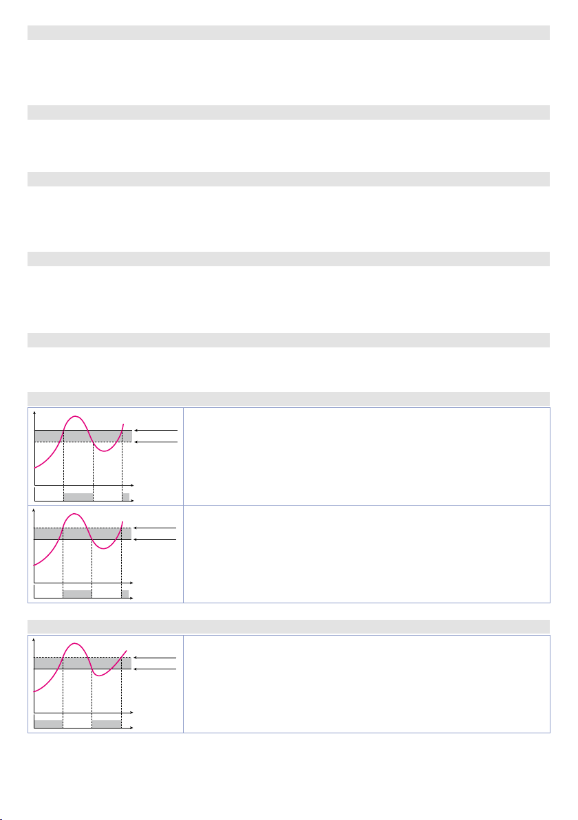
331
t m r.2
Timer 2
Enabling Timer 2
332
diS a b.
En ab.
En.S tA.
t. b. t.2
Disabled (Default)
Enabled
Enabled and active at start
Time Base Timer 2
Selects time base for timer 2
333
m m.SS
h h.M M
a.tm.2
minutes.seconds (Default)
hours.minutes
Action Timer 2
Select the type of the action executed by the timer 2 to be related to an alarm.
334
Start
End
W Ar n.
tM r. s .
Start. Active during timer counting (Default)
End. Active at timer expiry.
Warning. Active 5” before the timer expiry.
Timers Sequence
Select the correlation between the two timers.
Si nGL.
S eQ u e.
Loo P
Singles. Timers work independently (Default)
Sequential. When timer 1 ends, timer 2 starts.
Loop. When a timer ends, another starts.
335÷339 Reserved Parameters - Group W
Reserved parameters - Group W
14 Alarm Intervention Modes
14. a Absolute or threshold alarm active over (par. 123
Pv
Alarm Spv
Hysteresis parameter
> 0
Absolute alarm active over.
Hysteresis value greater than “0” (Par. 128
ON ON
OFF OFF
Pv
Time
Alarm output
Hysteresis parameter
< 0
Alarm Spv
Absolute alarm active over.
Hysteresis value lower than “0” (Par. 128
ON ON
OFF OFF
Time
Alarm output
A L .1 . F.
=
A b . u P. A.
)
a .1 . H Y > 0).
a .1 . H Y < 0).
14. b Absolute or threshold alarm active below (par. 123
Hysteresis parameter
> 0
Pv
ON
OFF OFF
66 - CN40x - User manual
Alarm Spv
Time
ON
Alarm output
Absolute alarm active below.
Hysteresis value greater than “0” (Par. 128
A L .1 . F.
=
A b . u P. A.
)
a .1 . H Y > 0).
Page 67
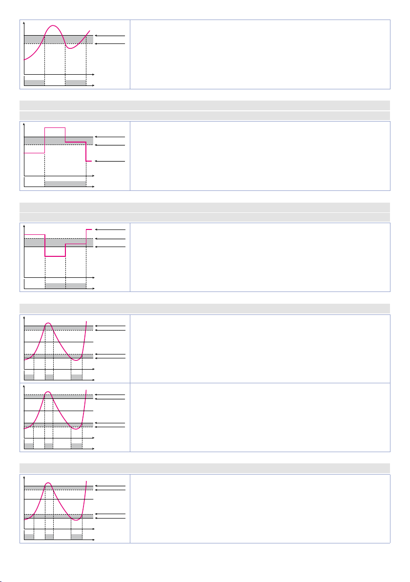
Pv
Alarm output
Alarm output
ON
ON
OFF OFF
Alarm Spv
Hysteresis parameter
< 0
Time
Alarm output
Absolute alarm active below.
Hysteresis value lower than “0” (Par. 128
a .1 . H Y < 0).
14.c Absolute or threshold alarm referred to command setpoint active over (par. 123
Ab . c. u.A.
)
Alarm Spv
Hysteresis parameter
OFF OFF
ON
> 0
Command Spv
Time
Alarm output
Absolute alarm referred to command setpoint active over. Hysteresis
value greater than “0” (Par. 128
a .1 . H Y > 0).
14.d Absolute or threshold alarm referred to command setpoint active below (par. 123
Ab . c.L.A.
)
Command Spv
Hysteresis parameter
> 0
Alarm Spv
ON
OFF OFF
Time
14.e Band alarm (par. 123
Pv
ON
ON ON
OFF OFF OFF
Pv
ON
ON ON
OFF OFF OFF
Command Spv
Command Spv
Alarm Spv
Hysteresis parameter
> 0
Hysteresis parameter
> 0
Alarm Spv
Time
Alarm output
Hysteresis parameter
< 0
Alarm Spv
Alarm Spv
Hysteresis parameter
< 0
Time
Absolute alarm referred to command setpoint active below.
Hysteresis value greater than “0” (Par. 128
A L .1 . F.
=
band
)
a .1 . H Y > 0).
Band alarm hysteresis value greater than “0” (Par. 128 a .1 . H Y > 0).
Band alarm hysteresis value lower than “0” (Par. 128 a .1 . H Y < 0).
A L .1 . F.
A L .1 . F.
=
=
14.f Asymmetric band alarm (par. 123
Pv
Command Spv
ON
ON ON
OFF OFF OFF
Alarm Spv H
Hysteresis parameter
> 0
Hysteresis parameter
> 0
Alarm Spv L
Time
Alarm output
Asymmetric band alarm with hysteresis value greater than “0” (Par.
128
a .1 . H Y > 0).
A L .1 . F.
=
A.band
)
User manual - CN40x- 67
Page 68
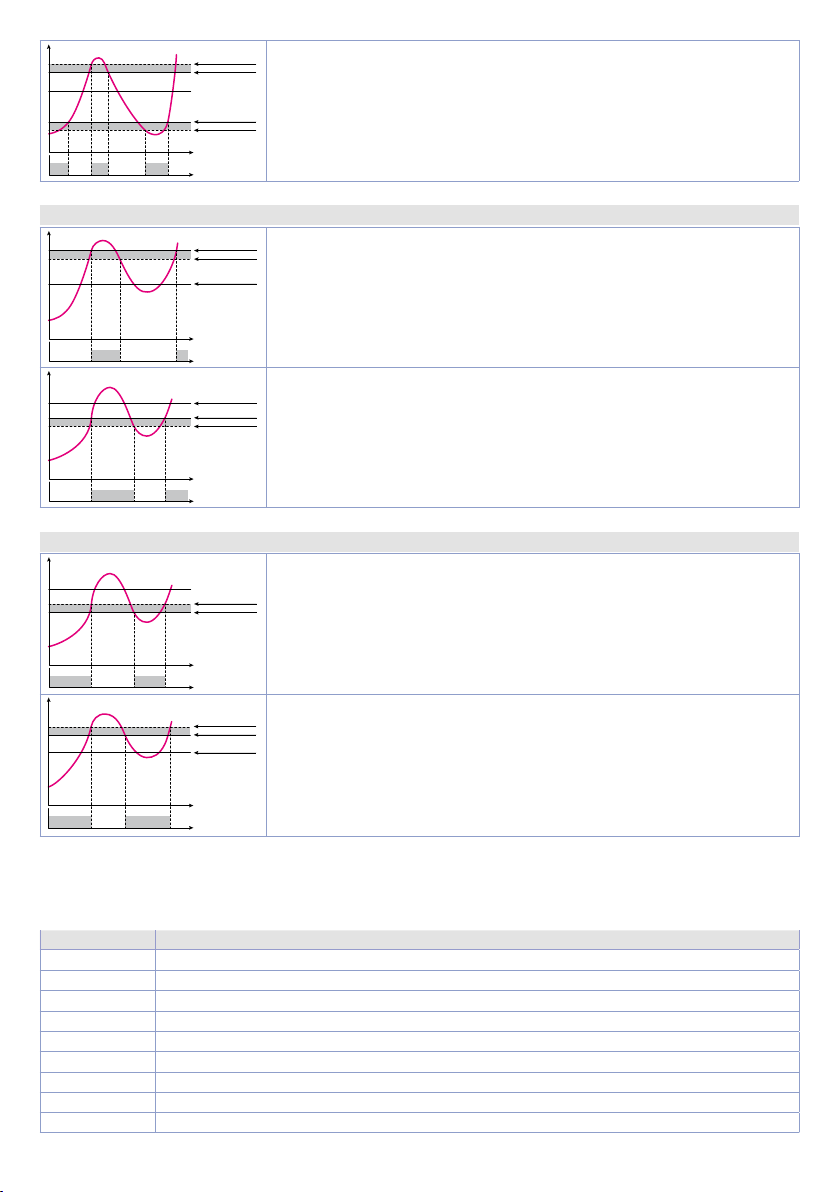
Pv
Alarm output
Alarm output
Alarm output
Command Spv
ON
ON ON
OFF OFF OFF
Hysteresis parameter
< 0
Alarm Spv H
Alarm Spv L
Hysteresis parameter
< 0
Time
Asymmetric band alarm with hysteresis value lower than “0” (Par. 128
a .1 . H Y < 0).
14.g Upper deviation alarm (par. 123
Pv
Alarm Spv
Hysteresis parameter
> 0
Command Spv
Upper deviation alarm value of alarm setpoint greater than “0” and
hysteresis value greater than “0” (Par.128
NB: with hysteresis value less than “0” (
ON ON
OFF OFF
Pv
Time
Command Spv
Alarm Spv
Hysteresis parameter
> 0
moves under the alarm setpoint.
Upper deviation alarm value of alarm setpoint less than “0” and
hysteresis value greater than “0” (Par.128
NB: with hysteresis value less than “0” (
ON ON
OFF OFF
Time
moves under the alarm setpoint.
14. h Lower deviation alarm (par. 123
Pv
Command Spv
Hysteresis parameter
> 0
Alarm Spv
Lower deviation alarm value of alarm setpoint greater than “0” and
hysteresis value greater than “0” (Par.128
NB: with hysteresis value less than “0” (
ON ON
OFF OFF
Pv
Time
Alarm output
Hysteresis parameter
> 0
Alarm Spv
Command Spv
moves under the alarm setpoint.
Lower deviation alarm value of alarm setpoint less than “0” and
hysteresis value greater than “0” (Par.128
NB: with hysteresis value less than “0” (
ON ON
OFF OFF
Time
Alarm output
moves under the alarm setpoint.
A L .1 . F.
A L .1 . F.
=
=
up.dev.
Lo.dev.
)
A .1 . H Y . > 0).
A .1 . H Y . < 0) the dotted line
A .1 . H Y . > 0).
A .1 . H Y . < 0) the dotted line
)
A .1 . H Y . > 0).
A .1 . H Y . < 0) the dotted line
A .1 . H Y . > 0).
A .1 . H Y . < 0) the dotted line
14.1 Alarms label
By setting a value from 1 to 20 on the parameters 136
A.5. Lb.
e 226
A.6.L b.
, the display 2 will show one of the following messages in case of alarm:
Selection Message displayed in the alar m event
1
2
3
4
5
6
7
8
9
68 - CN40x - User manual
alarm 1
alarm 2
alarm 3
alarm 4
alarm 5
alarm 6
open door
closed door
light on
A.1.L b.
, 154
A. 2.L b.
, 172
A.3.Lb.
, 190
A .4.L b .
, 208
Page 69

10
11
12
13
14
15
16
17
18
19
20
light off
warning
waiting
high limit
low limit
external alarm
temperature alarm
pressure alarm
fan command
cooling
operating
By setting 0, no message will be displayed. While setting 21, the user will have up to 23 characters
available to customize his message via the “Direct link | 400S Devices” App or via modbus.
15 Table of Anomaly Signals
If installation malfunctions, the controller switches off the regulation output and reports the anomaly
noticed. For example, controller will report failure of a connected thermocouple visualizing
(flashing) flashing on display.
For other signals see table below.
Cause What to do
E-02
SYSTEM
Erro r
E-0 4
eeprom
Erro r
E-05
PRob e 1
Erro r
E-0 6
PRob e 2
Erro r
E-0 8
SYSTEM
Erro r
E -1 0
a .i n .2
di s a b le d
E-8 0
r fi d
Erro r
Cold junction temperature sensor failure or
environment temperature out of range
Incorrect configuration data.
Possible loss of instrument calibration
Sensor connected to AI1 broken or
temperature out of range
Sensor connected to AI2 broken or
temperature out of range
Call assistance
Verify that configuration parameters are
correct.
Control connection with probes and their
integrity.
Control connection with probes and their
integrity.
Missing calibration Call assistance
Analogue input 2 disabled but used during
configuration.
Enable A .i n .2 or disable it during configuration.
Tag rfid malfunctioning Call assistance
e -05
Notes / Updates
1 Display of decimal point depends on setting of parameter sen. and parameter d . p.
2 On activation, the output is inhibited if the controller is in alarm mode. Activates only if alarm condition reappers, after that
it was restored.
3 Changing the control setpoint, the alarm will be disabled. It will stay disabled as long as the parameters that created it are
active. It only wo rks with deviation alarms, band a larms and absolute alarms (referring to the control setpoint).
User manual - CN40x- 69
Page 70

70 - CN40x - User manual
Page 71

Table of configuration parameters
GROUP A - A.in.1 - Analogue input 1
S E N .1
1
d .P. 1
2
d eGr.
3
L. L.i .1
u.L.i.1
5
P . v A .1
6
i.o.L.1
7
o . c A .1
8
G . c a .1
9
10
11
12
13
14÷17 Reserved Parameters - Group A 31
GROUP B - A.in.2 - Analogue input 2 (only on CN-x)
18
19
20
21
22
23
24
25
26
27
28
29
30
31÷34 Reserved Parameters - Group B 33
GROUP C - cmd.1 - Outputs and regulation Process 1
35
36
37
38
39
40
41
42
43
44
45
46
47
48
49
50
51
52÷53 Reserved Parameters - Group C 36
Sensor AI1 30
Decimal Point 1 30
Degree 30
Lower Linear Input AI1 30
Upper Linear Input AI1 30
Potentiometer Value AI1 30
Linear Input over Limits AI1 31
Offset Calibration AI1 31
Gain Calibration AI1 31
Lt c .1
Latch-On AI1 31
c . F L .1
Conversion Filter AI1 31
c . F r.1
Conversion Frequency AI1 31
L. c. E.1
Lower Current Error 1 31
SEN.2
Sensor AI2 32
d.P. 2
Decimal Point 2 32
rEs .
Reserved 32
L.L.i . 2
Lower Linear Input AI2 32
u.L.i.2
P. v A . 2
i. o.L.2
o . cA.2
G. ca .2
Ltc. 2
c.FL.2
c.Fr.2
L. c.E.2
c.ou.1
c . P r .1
rEs.
A c . t .1
c. H Y .1
L.L.S.1
U . L . S .1
c. r e .1
c. S . e .1
c . L d .1
c . d e .1
c . S . p .1
v A . t .1
a.ma.1
i ni .S.
S. vA.S.
i . S P .1
Upper Linear Input AI2 32
Potentiometer Value AI2 32
Linear Input over Limits AI2 33
Offset Calibration AI2 33
Gain Calibration AI2 33
Latch-On AI2 33
Conversion Filter AI2 33
Conversion Frequency AI2 33
Lower Current Error 2 33
Command Output 1 34
Command Process 1 (only on CN402-x) 34
Reserved 35
Action type 1 35
Command Hysteresis 1 35
Lower Limit Setpoint 1 35
Upper Limit Setpoint 1 35
Command Reset 1 35
Command State Error 1 35
Command Led 1 35
Command Delay 1 36
Command Setpoint Protection 1 36
Valve Time 1 36
Automatic / Manual 1 36
Initial State 36
State Valve Saturation 36
Initial Value Setpoint 1 36
User manual - CN40x- 71
Page 72

GROUP D - cmd.2 - Outputs and regul. Process 2 (only on CN-x)
c.ou.2
54
c.Pr.2
55
rEM.S.
56
Ac. t.2
57
c.HY.2
58
L.L.S.2
59
U.L.S.2
60
c.re.2
61
c.S. e.2
62
c.Ld.2
63
c.de.2
64
c. S. p.2.
65
vA. t.2
66
a.ma.2
67
rEs .
68
rEs .
69
i .S P.2
70
Command Output 2 37
Command Process 2 37
Remote Setpoint 37
Action type 2 37
Command Hysteresis 2 37
Lower Limit Setpoint 2 37
Upper Limit Setpoint 2 38
Command Reset 2 38
Command State Error 2 38
Command Led 2 38
Command Delay 2 38
Command Setpoint Protection 2 38
Valve Time 2 38
Automatic / Manual 2 39
Reserved 39
Reserved 39
Initial Value Setpoint 2 39
71÷72 Reserved Parameters - Group D 39
GROUP E - reG.1 - Autotuning and PID 1
t u n .1
73
74
75
76
77
78
79
80
81
82
83
84
85
86
87
88
89
90
91
92
93
Tune 1 39
s.d.t.1
p.b . 1
i. t. 1
d .t. 1
d .b. 1
p.b.c.1
o.o.s.1
o.d.t.1
c. t. 1
c o . F.1
P. b . M .1
o.d.b.1
c. c.t .1
L.L.P.1
U . L . p .1
m . G . t .1
m n . p .1
m a . p .1
mn.i.1
o . c . L .1
Setpoint Deviation Tune 1 39
Proportional Band 1 39
Integral Time 1 39
Derivative Time 1 39
Dead Band 1 39
Proportional Band Centered 1 40
Off Over Setpoint 1 40
Off Deviation Threshold 1 40
Cycle Time 1 40
Cooling Fluid 1 40
Proportional Band Multiplier 1 40
Overlap / Dead Band 1 40
Cooling Cycle Time 1 40
Lower Limit Output Percentage 1 40
Upper Limit Output Percentage 1 40
Max Gap Tune 1 41
Minimum Proportional Band 1 41
Maximum Proportional Band 1 41
Minimum Integral Time 1 41
Overshoot Control Level 1 41
94÷97 Reserved Parameters - Group E 41
GROUP F - reG.2 - Autotuning and PID 2 (only on CN-x)
tu n.2
98
99
100
101
102
103
104
105
72 - CN40x - User manual
Tune 2 41
s.d.t.2
Setpoint Deviation Tune 2 41
p. b. 2
Proportional Band 2 41
i. t. 2
Integral Time 2 41
d. t. 2
Derivative Time 2 42
d . b. 2
Dead Band 2 42
p.b.c.2
Proportional Band Centered 2 42
o.o.s.2
Off Over Setpoint 2 42
Page 73

106
o.d.t.2
Off Deviation Threshold 2 42
c.t. 2
107
108
109
110
111
112
113
114
115
116
117
118
Cycle Time 2 42
co.F.2
Cooling Fluid 2 42
P.b.M.2
Proportional Band Multiplier 2 42
o.d.b.2
c. c. t.2
L.L.P.2
U.L.p.2
m .G.t.2
m n.p.2
m a. p.2
mn.i.2
o.c.L.2
Overlap / Dead Band 2 42
Cooling Cycle Time 2 42
Lower Limit Output Percentage 2 42
Upper Limit Output Percentage 2 42
Max Gap Tune 2 43
Minimum Proportional Band 2 43
Maximum Proportional Band 2 43
Minimum Integral Time 2 43
Overshoot Control Level 2 43
119÷122 Reserved Parameters - Group F 43
GROUP G - AL. 1 - ALARM 1
AL.1 . f .
123
124
125
126
127
128
129
130
131
132
133
134
135
136
Alarm 1 Function 43
A .1 . P r .
Alarm 1 Process (only on CN402-x) 44
A.I. r.c.
Alarm 1 Reference Command (only on CN402-x) 44
A . I. 5 . o .
Alarm 1 State Output 44
rEs.
Reserved 44
a .1 . H y .
Alarm 1 Hysteresis 44
A.1. L.L.
Alarm 1 Lower Limit 44
A.1. u . L .
Alarm 1 Upper Limit 44
a .1 . r e .
Alarm 1 Reset 44
A .1 . S . e .
Alarm 1 State Error 45
A .1 . L d .
Alarm 1 Led 45
a .1 . d e .
Alarm 1 Delay 45
A .1 . S . p .
Alarm 1 Setpoint Protection 45
A.1. Lb .
Alarm 1 Label 45
137÷140 Reserved Parameters - Group G 45
GROUP H - AL. 2 - Alarm 2
AL. 2. f.
141
142
143
144
145
146
147
148
149
150
151
152
153
154
Alarm 2 Function 45
A.2.Pr.
Alarm 2 Process (only on CN402-x) 46
A.2. r. c.
Alarm 2 Reference Command (only on CN402-x) 46
A. 2.5. o .
Alarm 2 State Output 46
rEs.
Reserved 46
a.2.Hy.
Alarm 2 Hysteresis 46
A.2.L.L.
Alarm 2 Lower Limit 46
A. 2. u .L.
Alarm 2 Upper Limit 46
a.2. r e.
Alarm 2 Reset 46
A.2. S. e .
Alarm 2 State Error 47
A.2.Ld.
Alarm 2 Led 47
a .2. d e.
Alarm 2 Delay 47
A.2.S. p .
Alarm 2 Setpoint Protection 47
A.2.Lb.
Alarm 2 Label 47
155÷158 Reserved Parameters - Group H 47
GROUP I - AL. 3 - Alarm 3
AL.3.f.
159
160
161
Alarm 3 Function 47
A.3. P r.
Alarm 3 Process (only on CN402-x) 48
A.3.r. c.
Alarm 3 Reference Command (only on CN402-x) 48
User manual - CN40x- 73
Page 74

162
A.3.5.o .
Alarm 3 State Output 48
A.3.o.t.
163
164
165
166
167
168
169
170
171
172
Alarm 3 Output Type 48
a .3.Hy .
Alarm 3 Hysteresis 48
A.3.L.L
Alarm 3 Lower Limit 48
A. 3. u . L.
Alarm 3 Upper Limit 48
a.3. re.
Alarm 3 Reset 48
A.3.S. e.
Alarm 3 State Error 49
A. 3.Ld .
Alarm 3 Led 49
a .3.de .
Alarm 3 Delay 49
A.3.S. p.
Alarm 3 Setpoint Protection 49
A.3. Lb .
Alarm 3 Label 49
173÷176 Reserved Parameters - Group I 49
GROUP J - AL. 4 - Alarm 4
AL.4. f.
177
178
179
180
181
182
183
184
185
186
187
188
189
190
Alarm 4 Function 49
A.4 .Pr.
Alarm 4 Process (only on CN402-x) 50
A.4.r. c.
Alarm 4 Reference Command 50
A.4. 5. o .
Alarm 4 State Output 50
A.4.o.t.
Alarm 4 Output Type 50
a .4. H y .
Alarm 4 Hysteresis 50
A.4.L.L
Alarm 4 Lower Limit 50
A.4. u . L.
Alarm 4 Upper Limit 50
a .4. r e.
Alarm 4 Reset 51
A .4. S. e .
Alarm 4 State Error 51
rES.
Reserved 51
a .4 . d e .
Alarm 4 Delay 51
A .4. S. p .
Alarm 4 Setpoint Protection 51
A .4. Lb .
Alarm 4 Label 51
191÷194 Reserved Parameters - Group J 51
GROUP K - AL. 5 - Alarm 5 (only on CN- and CN-x)
AL.5. f.
195
196
197
198
199
200
201
202
203
204
205
206
207
208
Alarm 5 Function 51
A.5.P r.
Alarm 5 Process (only on CN402-x) 52
A.5.r.c.
Alarm 5 Reference Command (only on CN402-x) 52
A.5.5. o .
Alarm 5 State Output 52
A.5.o.t.
Alarm 5 Output Type 52
a.5.Hy .
Alarm 5 Hysteresis 52
A. 5.L.L.
Alarm 5 Lower Limit 52
A.5. u . L.
Alarm 5 Upper Limit 53
a.5.re.
Alarm 5 Reset 53
A.5.S.e.
Alarm 5 State Error 53
rES.
Reserved 53
a.5. d e.
A.5.S. p.
A.5. Lb .
Alarm 5 Delay 53
Alarm 5 Setpoint Protection 53
Alarm 5 Label 53
209÷212 Reserved Parameters - Group K 53
GROUP L - AL. 6 - Alarm 6 (only on CN-x)
AL. 6. f.
213
214
215
216
217
74 - CN40x - User manual
Alarm 6 Function 53
A.6.Pr.
Alarm 6 Process 54
A.6. r. c.
Alarm 6 Reference Command 54
A.6.5.o .
Alarm 6 State Output 54
A.6. o.t.
Alarm 6 Output Type 54
Page 75

218
a.6.Hy .
Alarm 6 Hysteresis 54
A.6.L.L.
219
220
221
222
223
224
225
226
Alarm 6 Lower Limit 55
A.6. u.L.
Alarm 6 Upper Limit 55
a .6. re.
Alarm 6 Reset 55
A.6.S.e.
Alarm 6 State Error 55
rES.
Reserved 55
a.6.de.
Alarm 6 Delay 55
A.6.S.p.
Alarm 6 Setpoint Protection 55
A.6.Lb.
Alarm 6 Label 55
227÷230 Reserved Parameters - Group L 55
GROUP M - d.i. 1 - Digital input 1
d.i.1.f.
231
232
233
234
Digital Input 1 Function 55
d.i.1.c.
Digital Input 1 Contact 56
d.i.1.P.
Digital Input 1 Process (only on CN402-x) 56
d.i.1.r.
Digital Input 1 Reference Command 56
235÷238 Reserved Parameters - Group M 56
GROUP N - d.i. 2 - Digital input 2
d.i.2.f.
239
240
241
242
Digital Input 2 Function 57
d.i.2.c.
Digital Input 2 Contact 57
d.i.2.P.
Digital Input 2 Process (only on CN402-x) 57
d.i.2.r.
Digital Input 2 Reference Command 57
243÷246 Reserved Parameters - Group N 57
GROUP O - d.i. 3 - Digital input 3 (only on CN-x)
d.i .3.f.
247
248
249
250
Digital Input 3 Function 58
d.i.3.c.
Digital Input 3 Contact 58
d.i.3.P.
Digital Input 3 Process 58
d.i.3.r.
Digital Input 3 Reference Command 58
251÷254 Reserved Parameters - Group O 58
GROUP P - d.i. 4 - Digital input 4 (only on CN-x)
d.i.4.f.
255
256
257
258
Digital Input 4 Function 59
d.i.4.c.
Digital Input 4 Contact 59
d .i .4.P.
Digital Input 4 Process 59
d.i.4.r.
Digital Input 4 Reference Command 59
259÷262 Reserved Parameters - Group P 59
GROUP Q - sft.s - Soft-start and mini cycle
Pr. cY .
263
264
265
266
267
268
269
270
271
272
Pre-programmed Cycle 60
SS.TY.
Soft-Start Type 60
ss.r.c.
Soft-Start Reference Command (only on CN402-x) 60
SS. G r.
Soft-Start Gradient 60
SS.Pe.
Soft-Start Percentage 60
SS. tH.
Soft-Start Threshold 60
SS . ti .
Soft-Start Time 60
M A . ti .
Maintenance Time 60
FA .Gr.
Falling Gradient 60
de.st.
Delayed Start 60
273÷276 Reserved Parameters - Group Q 60
GROUP R - disp. - Display and interface
v .FLt
277
278
Visualization Filter 61
vi.d.2
Visualization Display 2 61
User manual - CN40x- 75
Page 76

279
tMo.d.
Timeout Display 61
tMo .S.
280
281
282
283
284
285
286
Timeout Selection 61
u .M.P. c.
User Menu Pre-Programmed Cycle 61
v.out
Voltage Output 61
ScL. t.
Scrolling Time 62
d . SP. F.
Display Special Functions 62
nFc. L.
NFC Lock 62
s.k.s.f.
Set Key Special Functions 62
GROUP S - ct - Current transformer (only on CN- and CN-x)
287
ct F.
Current Transformer Function 62
ct v .
288
289
290
291
292
Current Transformer Value 62
H.b.a.r.
Heater Break Alarm Reference Command 62
H.b.a.t.
o cu. t.
H.b.a.d.
Heater Break Alarm Threshold 62
Overcurrent Alarm Threshold 62
Heater Break Alarm Delay 63
293÷297 Reserved Parameters - Group S 63
GROUP T - a.o. 1 - Retransmission 1
r t M .1
298
299
300
301
302
Retransmission 1 63
r.1 . t y .
Retransmission 1 Type 63
r.1. L.L.
Retransmission 1 Lower Limit 63
r.1. u.L.
Retransmission 1 Upper Limit 63
r.1 . s . e .
Retransmission 1 State Error 63
303÷307 Reserved Parameters - Group T 63
GROUP U - a.o. 2 - Retransmission 2 (only on CN-x)
rtM.2
308
309
310
311
312
Retransmission 2 64
r.2. ty .
Retransmission 2 Type 64
r.2. L.L.
Retransmission 2 Lower Limit 64
r.2. u .L.
r.2. s . e .
Retransmission 2 Upper Limit 64
Retransmission 2 State Error 64
313÷317 Reserved Parameters - Group U 64
GROUP V - ser. - Seriale (not available on CN-)
sL. a d .
318
319
320
321
322
Slave Address 65
bd .rt.
Baud Rate 65
s.p. p.
Serial Port Parameters 65
se.de.
Serial Delay 65
o f f.L.
Off Line 65
323÷327 Reserved Parameters - Group V 65
GROUP W - timr - Timer
t m r .1
328
329
330
331
332
333
334
Timer 1 65
t.b. t.1
Time Base Timer 1 65
a.tm.1
Action Timer 1 65
tm r. 2
Timer 2 66
t. b. t.2
Time Base Timer 2 66
a.tm.2
Action Timer 2 66
tM r. s .
Timers Sequence 66
335÷339 Reserved Parameters - Group W 66
76 - CN40x - User manual
Page 77

OMEGA ENGINEERING, INC. warrants this unit to be free of defects in materials and workmanship
WARRANTY / DISCLAIMER
for a period of 13 months from date of purchase. OMEGA’s Warranty adds an additional one (1)
month grace period to the normal one (1) year product warranty to cover handling and shipping
time. This ensures that OMEGA’s customers receive maximum coverage on each product.
If the unit malfunctions, it must be returned to the factory for evaluation. OMEGA’s Customer
Service Department will issue an Authorized Return (AR) number immediately upon phone or
written request. Upon examination by OMEGA, if the unit is found to be defective, it will be repaired
or replaced at no charge. OMEGA’s WARRANTY does not apply to defects resulting from any action
of the purchaser, including but not limited to mishandling, improper interfacing, operation outside
of design limits, improper repair, or unauthorized modication. This WARRANTY is VOID if the
unit shows evidence of having been tampered with or shows evidence of having been damaged
as a result of excessive corrosion; or current, heat, moisture or vibration; improper specication;
misapplication; misuse or other operating conditions outside of OMEGA’s control. Components in
which wear is not warranted, include but are not limited to contact points, fuses, and triacs.
OMEGA is pleased to offer suggestions on the use of its various products. However,
OMEGA neither assumes responsibility for any omissions or errors nor assumes
liability for any damages that result from the use of its products in accordance with
information provided by OMEGA, either verbal or written. OMEGA warrants only
that the parts manufactured by the company will be as specied and free of defects.
OMEGA MAKES NO OTHER WARRANTIES OR REPRESENTATIONS OF ANY KIND
WHATSOEVER, EXPRESSED OR IMPLIED, EXCEPT THAT OF TITLE, AND ALL IMPLIED
WARRANTIES INCLUDING ANY WARRANTY OF MERCHANTABILITY AND FITNESS
FOR A PARTICULAR PURPOSE ARE HEREBY DISCLAIMED. LIMITATION OF LIABILITY:
OMEGA with respect to this order, whether based on contract, warranty, negligence,
indemnication, strict liability or otherwise, shall not exceed the purchase price of
the component upon which liability is based. In no event shall OMEGA be liable for
consequential, incidental or special damages.
CONDITIONS: Equipment sold by OMEGA is not intended to be used, nor shall it be used: (1) as
a “Basic Component” under 10 CFR 21 (NRC), used in or with any nuclear installation or activity;
or (2) in medical applications or used on humans. Should any Product(s) be used in or with any
nuclear installation or activity, medical application, used on humans, or misused in any way,
OMEGA assumes no responsibility as set forth in our basic WARRANTY/DISCLAIMER language,
and, additionally, purchaser will indemnify OMEGA and hold OMEGA harmless from any liabilit y or
damage whatsoever arising out of the use of the Product(s) in such a manner.
Direc t all warrant y and repair requests/inquiries to the OMEGA Customer Service Department.
RETURN REQUESTS/INQUIRIES
BEFORE RETURNING ANY PRODUCT(S) TO OMEGA, PURCHASER MUST OBTAIN AN AUTHORIZED
RETURN (AR) NUMBER FROM OMEGA’S CUSTOMER SERVICE DEPARTMENT (IN ORDER TO AVOID
PROCESSING DELAYS). The assigned AR number should then be marked on the outside of the
return package and on any correspondence. The purchaser is responsible for shipping charges,
freight, insurance and proper packaging to prevent breakage in transit.
FOR WARRANTY RETURNS
the following information available BEFORE
contacting OMEGA:
1. Purchase Order number under which the
product was PURCHASED,
2. Model and serial number of the product under
warranty, and
3. Repair instructions and/or specic problems
relative to the product.
OMEGA’s policy is to make running changes, not model changes, whenever an improvement
is possible. This affords our customers the latest in technology and engineering. OMEGA is a
registered trademark of OMEGA ENGINEERING, INC.
© Copyright 2013 OMEGA ENGINEERING, INC. All rights reser ved. This document may not be
copied, photocopied, reproduced, translated, or reduced to any electronic medium or machine-re
adable form, in whole or in part, without the prior written consent of OMEGA ENGINEERING, INC.
, please have
FOR NON-WARRANTY REPAIRS
OMEGA for current repair charges. Have
the following information available BEFORE
contacting OMEGA:
1. Purchase Order number to cover the COST of
the repair,
2. Model and serial number of the product, and
3. Repair instructions and/or specic problems
relative to the product.
, cons ult
-
Page 78

Where Do I Find Everything I Need for
Process Measurement and Control?
OMEGA…Of Course!
Shop online at omega.com
TEMPERATURE
Thermocouple, RTD & Thermistor Probes, Connectors, Panels & Assy
Wire: Thermocouple, RTD & Thermistor
Calibrators & Ice Point References
Recorders, Controllers & Process Monitors
Infrared Pyrometers
PRESSURE, STRAIN AND FORCE
Transducers & Strain Gages
Load Cells & Pressure Gages
Displacement Transducers
Instrumentation & Accessories
FLOW/LEVEL
Rotameters, Gas Mass Flowmeters & Flow Computers
Air Velocity Indicators
Turbine/Paddlewheel Systems
Totalizers & Batch Controllers
PH/CONDUCTIVITY
pH Electrodes, Testers & Accessories
Benchtop/Laboratory Meters
Controllers, Calibrators, Simulators & Pumps
Industrial pH & Conductivity Equipment
DATA ACQUISITION
Data Acquisition & Engineering Software
Communications-Based Acquisition Systems
Plug-in Cards for Apple, IBM & Compatibles
Data Logging Systems
Recorders, Printers & Plotter
HEATERS
Heating Cable
Cartridge & Strip Heaters
Immersion & Band Heaters
Flexible Heaters
Laboratory Heaters
ENVIRONMENTAL MONITORING AND CONTROL
Metering & Control Instrumentation
Refractometers
Pumps & Tubing
Air, Soil & Water Monitors
Industrial Water & Wastewater Treatment
pH, Conductivity & Dissolved Oxygen Instruments
2300.10.302-RevP - 130720 M-5758
 Loading...