

Page 1
omega.com
®
®
User’s Guide
http://www.omega.com
e-mail: [email protected]
Universal T emperature & Pr ocess
CN3430 & CN3440 SERIES
Controllers
Programming Guide
Page 2

omega.com
®
®
OMEGAnet®On-Line Service Internet e-mail
http://www.omega.com [email protected]
Servicing North America:
USA:
ISO 9001 Certified
Canada:
For immediate technical or application assistance:
USA and Canada:
Mexico and
Latin America:
Benelux:
One Omega Drive, Box 4047
Stamford, CT 06907-0047
Tel: (203) 359-1660 FAX: (203) 359-7700
e-mail: [email protected]
976 Bergar
Laval (Quebec) H7L 5A1
Tel: (514) 856-6928 FAX: (514) 856-6886
e-mail: [email protected]
Sales Service: 1-800-826-6342 / 1-800-TC-OMEGA
Customer Service: 1-800-622-2378 / 1-800-622-BEST
Engineering Service: 1-800-872-9436 / 1-800-USA-WHEN
TELEX: 996404 EASYLINK: 62968934 CABLE: OMEGA
Tel: (95) 800-826-6342 FAX: (95) 203-359-7807
En Espan˜ol: (95) 203-359-7803 e-mail: [email protected]
SM
SM
SM
Servicing Europe:
Postbus 8034, 1180 LA Amstelveen, The Netherlands
Tel: (31) 20 6418405 FAX: (31) 20 6434643
Toll Free in Benelux: 0800 0993344
e-mail: [email protected]
Czech Republic:
France:
Germany/Austria:
United Kingdom:
ISO 9002 Certified
It is the policy of OMEGA to comply with all worldwide safety and EMC/EMI regulations that
apply. OMEGA is constantly pursuing certification of its products to the European New Approach
Directives. OMEGA will add the CE mark to every appropriate device upon certification.
The information contained in this document is believed to be correct, but OMEGA Engineering, Inc. accepts
no liability for any errors it contains, and reserves the right to alter specifications without notice.
WARNING: These products are not designed for use in, and should not be used for, patient-connected applications.
ul. Rude armady 1868, 733 01 Karvina-Hranice
Tel: 420 (69) 6311899 FAX: 420 (69) 6311114
Toll Free: 0800-1-66342 e-mail: [email protected]
9, rue Denis Papin, 78190 Trappes
Tel: (33) 130-621-400 FAX: (33) 130-699-120
Toll Free in France: 0800-4-06342
e-mail: [email protected]
Daimlerstrasse 26, D-75392 Deckenpfronn, Germany
Tel: 49 (07056) 3017 FAX: 49 (07056) 8540
Toll Free in Germany: 0130 11 21 66
e-mail: [email protected]
One Omega Drive, River Bend Technology Centre
Northbank, Irlam, Manchester
M44 5EX, United Kingdom
Tel: 44 (161) 777-6611 FAX: 44 (161) 777-6622
Toll Free in the United Kingdom: 0800-488-488
e-mail: [email protected]
Page 3

CONTENTS
Section Page
1 INTRODUCTION ................................. 2
2 GENERAL PROGRAMMING .............. 2
2.1 Preparation for Changes
to the Parameters........................ 2
3 SELECTING THE CONTROL TYPE... 3
4 CONFIGURATION ............................... 4
4.1 Profile Program Page .................. 4
4.2 Set Points Page ........................... 6
4.3 Motorized Valve Control ............. 11
4.3.1 Position
Feedback Page .............. 12
4.4 Motorized Valve Control
without Feedback (Boundless).. 13
4.4.1 Calculation for Control
Pulses Steps and
Deviation (Boundless
Control Only) .................. 13
4.4.2 Regulator Data Page ..... 14
4.5 Set Up Process Variable............ 15
4.5.1 Set Up Process
V ariable Input Page........ 16
4.6 Set Up Remote Set Point Page . 20
4.7 Set Up Position
Feedback Page ......................... 22
4.8 Set Up Display Page ................. 24
4.9 Current Proportioning
Output Page .............................. 25
4.10 Set Up Control Page ................. 28
4.11 Set Up Alarms Page .................. 37
4.12 Retransmission Output Page .... 44
4.13 Cool Output Page ...................... 44
4.14 Scale Adjustment Page ............. 45
4.15 Access Page.............................. 48
1
Page 4
2 GENERAL PROGRAMMING1 INTRODUCTION
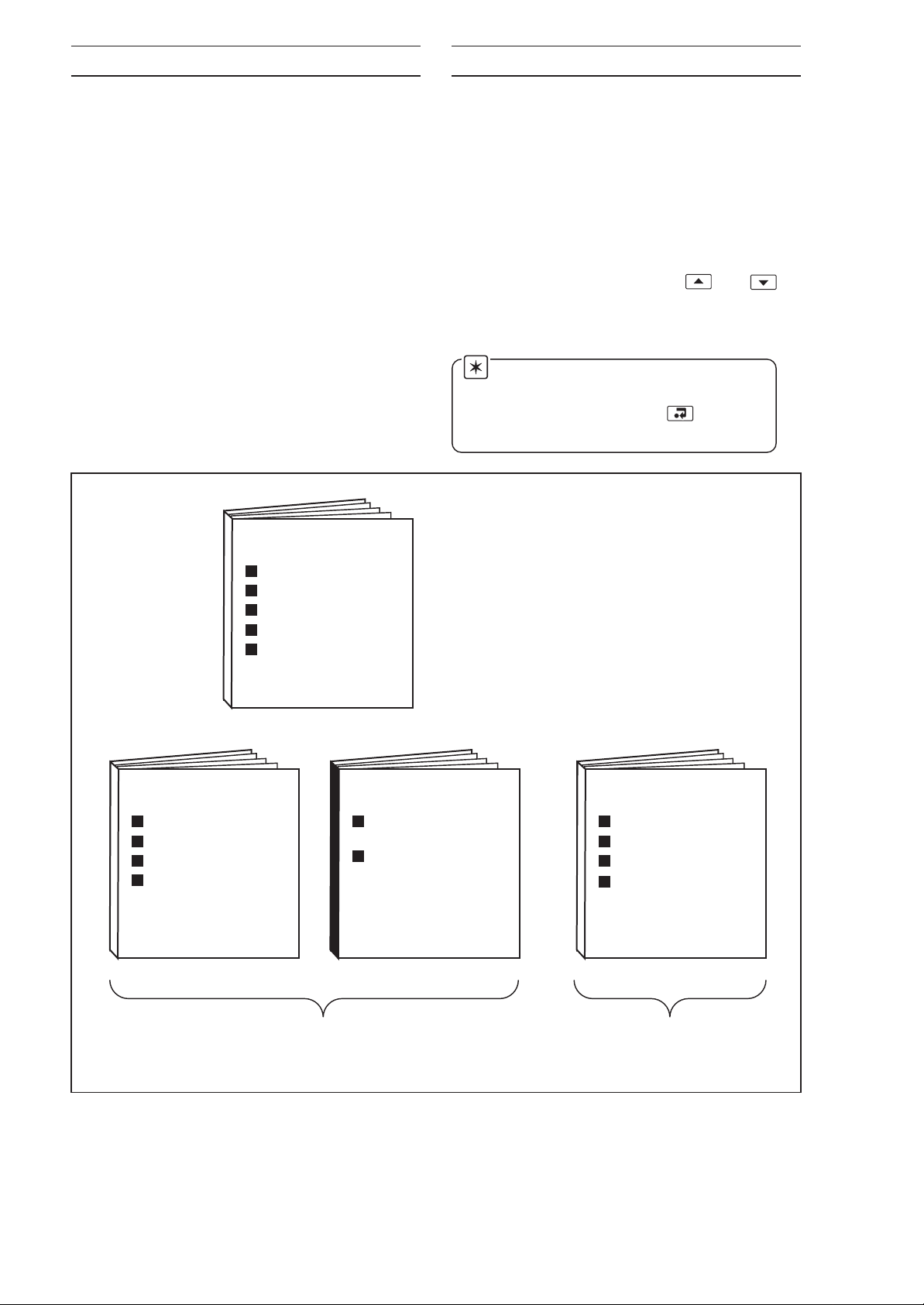
Documentation for the universal process
controller is shown in Fig. 1.1. The
Manuals
The
are supplied with all instruments.
MODBUS Supplement is supplied with
Standard
instruments configured for MODBUS Serial
Communication.
The Installation manual includes an
Installation Record which should be
completed as a log of the electrical
installation. The record is useful when
carrying out initial instrument programming
and can be retained for future reference.
INSTALLATION
2.1 Preparation for
Changes to the Parameters
Ensure that the external alarm/control
circuits are isolated if inadvertent
operation during programming is
undesirable.
Any changes to the operating parameters
are implemented using the or
switches – see
Guide
.
Note. The instrument responds
instantly to parameter changes which
are saved when the key is
pressed.
Section 3 of the Operating
OPERATION
Setting Up
Displays & Controls
Operating Level
Simple Fault-Finding
Product Identification
Siting
Mounting
Electrical Connections
Installation Record
PROGRAMMING
Basic
Configuration Level
Advanced
Configuration Level
MODBUS (RTU)
Serial Adaptors
Serial Connections
Programming Page
MODBUS Registers
Standard Manuals MODBUS Supplement
Fig. 1.1 Controller Documentation
2
Page 5
3 SELECTING THE CONTROL TYPE
Operating Page
100.3
110.5
ACCESS
PAGE
SCALE
AdJUSt
rEtrAN
OUtPUt
or
COOL
OUtPUt
ACKNLG
ALArMS
P-StAt
PAGE
SECOdE
PAGE
PrOFLE
StAtES
SELF
tunE
ContrL
PAGE
PrOFLE
PrOGr
SEtUP
ALArMS
SEtUP
PSN-Fb
dISPLY
PAGE
or
C–ProP
OUtPUt
SEtUP
rSPt
SEtUP
CONtrL
C–tYPE
C–PrOP
t–PrOP
P–PrOP
bndLSS
SEt
POINtS
POStN
F-bACK
or
SEtUP
PrCESS
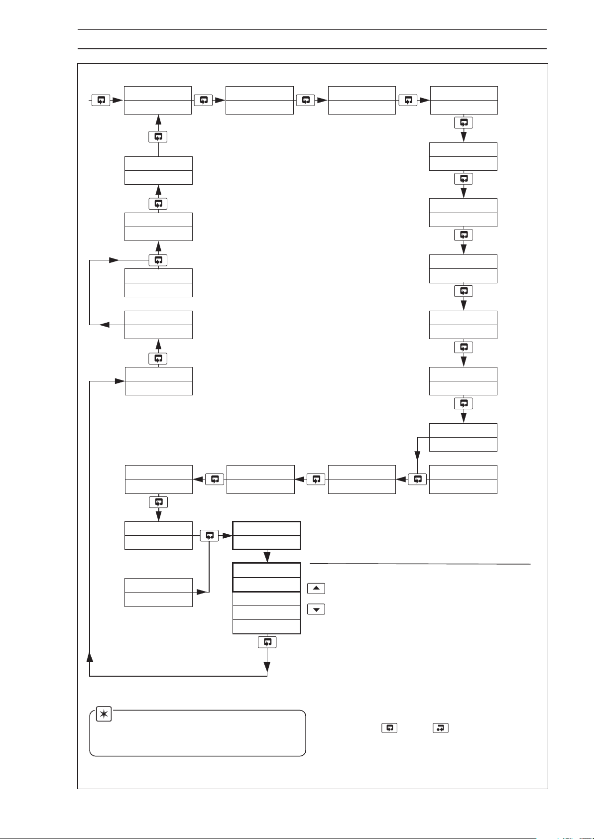
Page Header – Set Up Control.
Control Type – see Section 4.10
Select the control type required:
C–PrOP
t–PrOP
P–PrOP
bndLSS
–
current proportioning.
–
time proportioning.
–
position proportioning –
motorized valve with
position feedback.
–
boundless – motorized
valve without position
feedback.
rEGLtr
dAtA
Note. It is recommended that the
control type is set up before the
instrument is configured.
Fig. 3.1 Selecting the Control Type
Press then to return to the
Operating Page
.
3
Page 6
4 CONFIGURATION
4.1 Profile Program Page
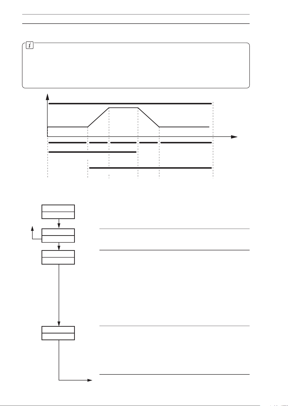
Information.
• This page is inaccessible when a profile is running.
• Up to 9 programs.
• Total of 30 segments.
• Guaranteed Ramp/Soak feature.
• Repeat facility for each program.
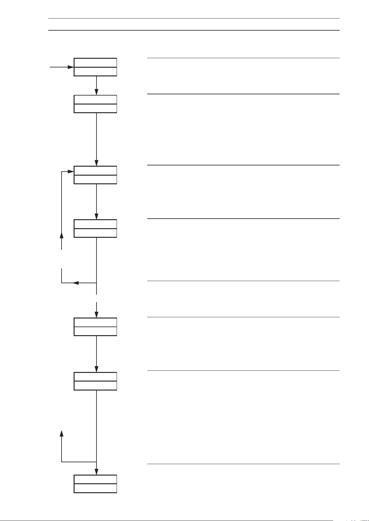
Overall Profile
Eng.
Units
Segment
Numbers
OFF
S1
Start at S1
L0
PrOFLE
PrOGrM
PrOFLE
PrOGrM
Program 1
OFF
ON
1
S2 S3
End at S3
Start at S2 End at S5
L1
L2 L3 L4 L5
Levels (0 to 5)
S4 S5
Program 2
Page Header – Profile Program.
Profile Enable
Select the profile function,
on or OFF.
Program Select
Select the program required. A program consists of a number
of segments. Each segment has a starting and finishing set
point level.
Level 1 is the finishing level of segment 1 and the
starting level of segment 2.
Level 10 is the finishing level of segment 10 and the
starting level of segment 11.
Time
PG–bEG
0
Program Begin (start level)
This is the first level number of the program selected at
Program Select above.
Set the program start level number for the program chosen
Program Select
at
Continued on next page.
4
Page 7
…4.1 Profile Program Page
4 CONFIGURATION…
More
segments
to set up
PG –ENd
30
LEU.L0x
1.0
LEVL
– – – –
xtIME
xx
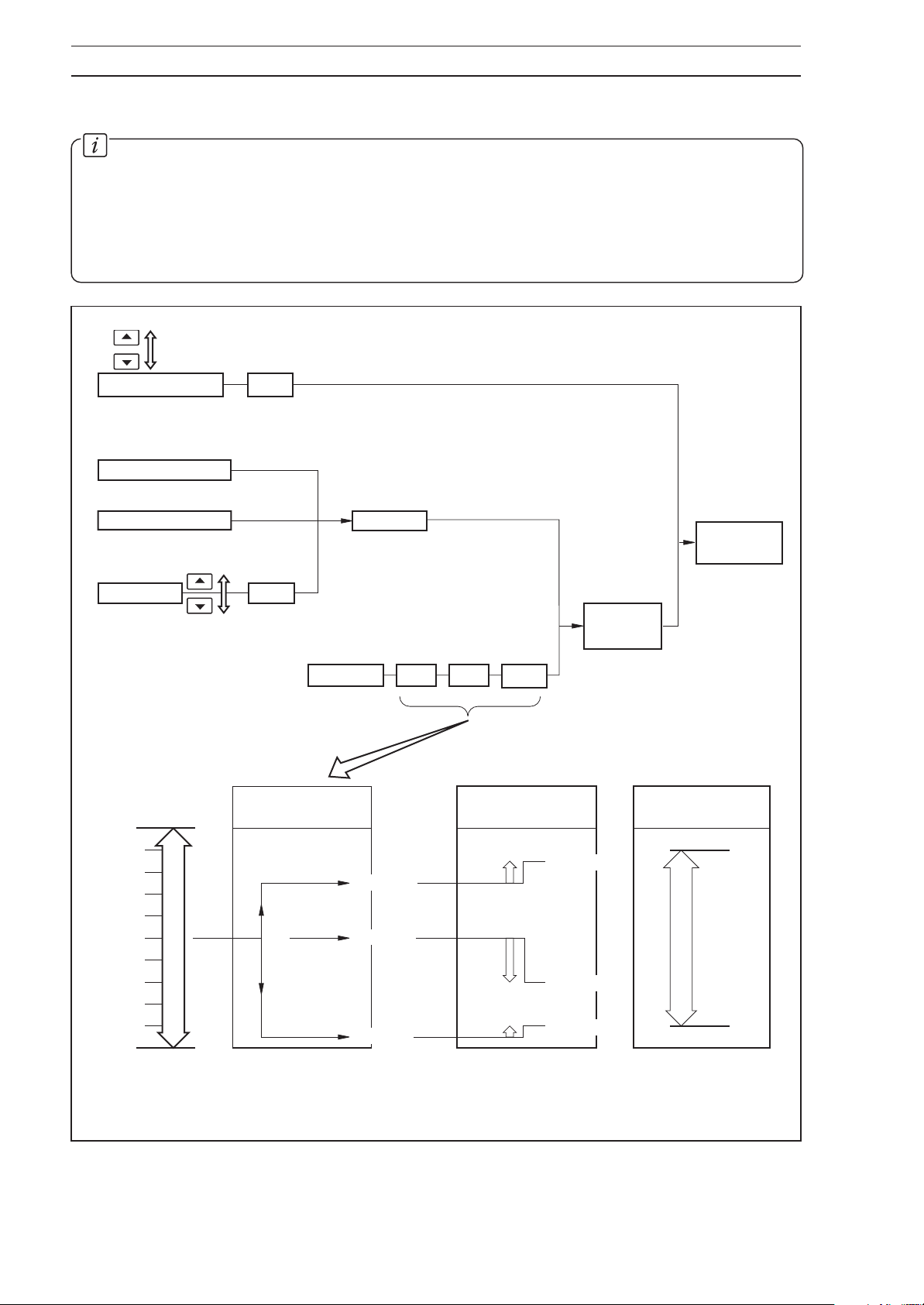
Program End (finish level)
Set the program end level number for the program chosen
at
Program Select.
Program First Segment Start Level
The number shown in the upper display is the start level
number for the first segment.
Set the required value for the start level.
The units are display units between
Display Full Scale.
Segment Time Period
The time number of the currently selected segment is
shown in the upper display.
Set the required time period, between 0 and 999.9 minutes
in 0.1-minute increments.
Segment Finish/Start Level
The number shown in the upper display is the finish level
number for the currently selected segment and the start
number for the next segment.
Set the required value for the segment finish/start level. The
units are display units between display zero and full scale.
Display Zero and
Last segment
rEPEAt
0
HYSt
Advance to the next parameter, Segment Time Period, if
more segments are to be set up or
segment is the last segment.
Program Repeat
Each program can be set to repeat up to 99 times or
continuously.
Set the required repeat count, between 0 and 99, or
Repeat if the current
InFntE for continuous repeats.
Program Hysteresis Value (for guaranteed ramp/soak)
0
A hysteresis value can be set in engineering units. Setting
the value to zero turns the guaranteed ramp/soak facility
off. If the process variable deviates beyond the value set,
the program is suspended, but resumes automatically
when the process variable returns within the set limits. The
hysteresis value applies above and below the set point
under all program conditions.
Set the hysteresis value required, within the display range
limits.
SEt
POINtS
Return to top of Profile Program Page
or
advance to
Set Points Page.
5
Page 8
…4 CONFIGURATION
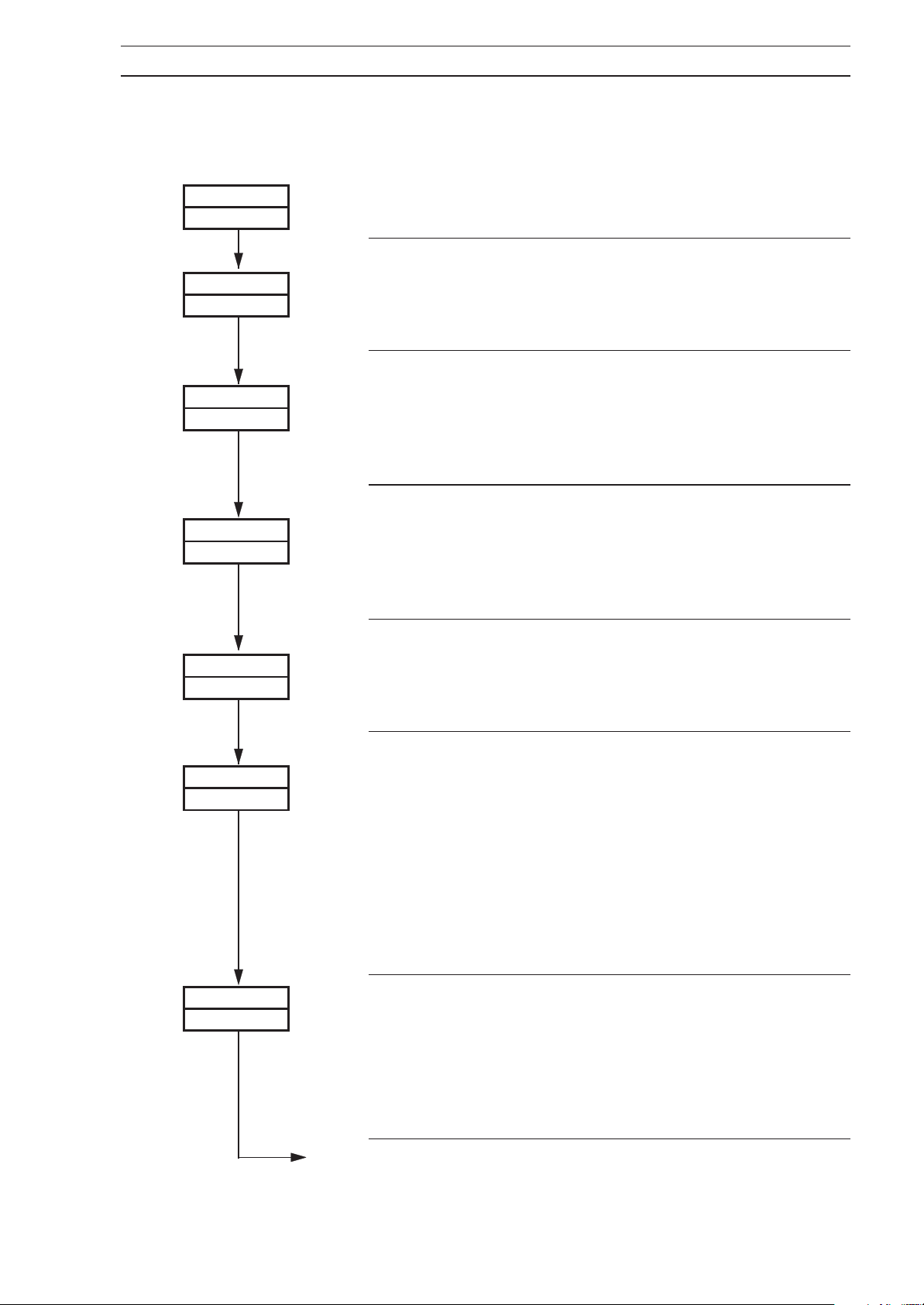
4.2 Set Points Page
Information.
• Two local set points – Local and Dual.
• Remote set point facility – with Ratio and Bias.
• Remote set point tracking options – for bumpless Remote-to-Local set point transfers.
• Adjustable high and low limits for all set point types.
• Set point tracking for bumpless Manual-to-Auto transfers.
Adjustable limits
Local Set Point
Digitally Selectable Set Points
Fixed Set Point 1
Fixed Set Point 2
Adjustable limits
Dual
100
Limits
Limits
Ratio Setting
(0.010 to 9.999)
1.5
Programmable Set Point Types
Dual
Remote
Ratio Bias Limits
Bias Setting
(within Eng. range)
+10
SP = 75
Set Point
SP = 85
Second
(within Eng. range)
High Limit*
Control
Set Point
Limits
90
Set
Point
6
50
1.0
0.1
Engineering Range
0
SP = 50
–20
SP = 30
SP = 5
* Set Point cannot be adjusted outside the limits set
Fig. 4.1 Set Point Types
+5
SP = 10
Low Limit*
10
Page 9
4 CONFIGURATION…
…4.2 Set Points Page
To gain access to this and subsequent pages, the correct configuration code must first be set
in the Security Code Page – see
Section 5.5 of the Operating Guide
.
SEt
POINtS
SP–AdJ
YES
LSP–HI
1000
LSP–LO
0
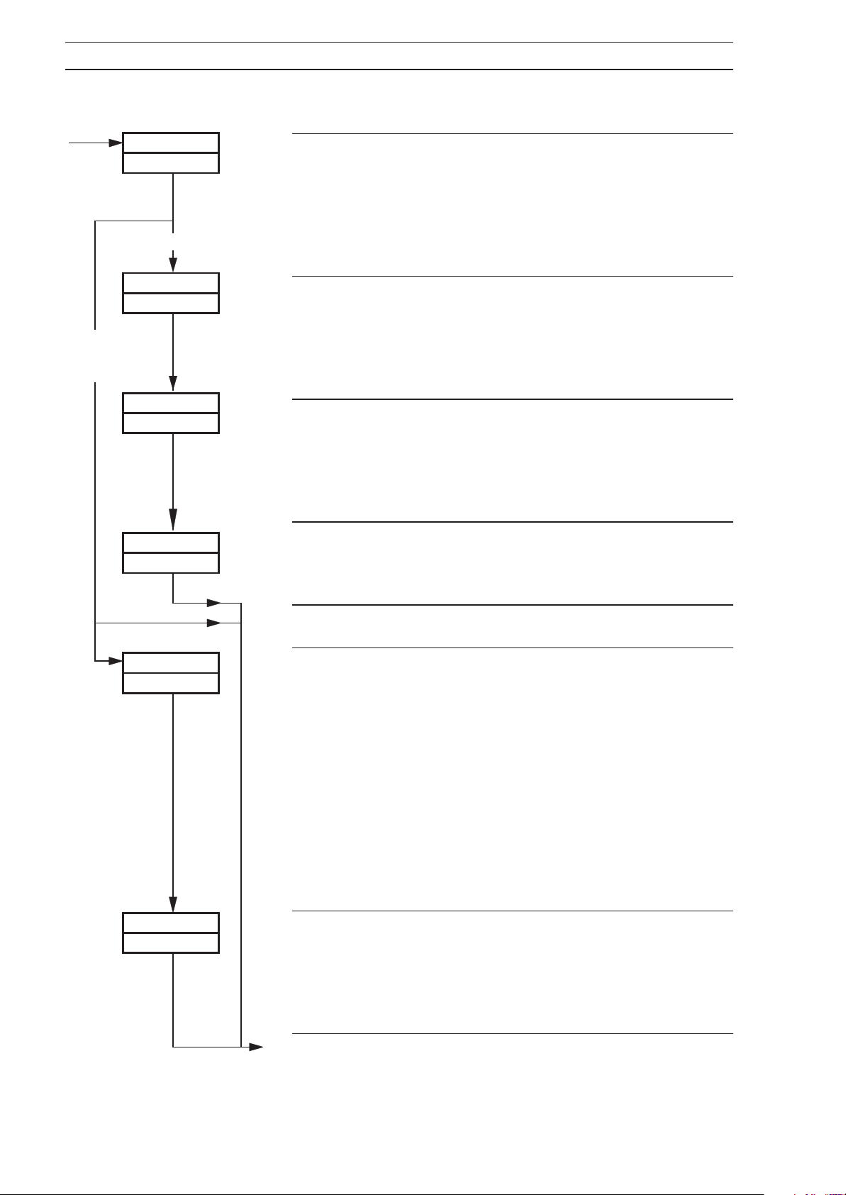
Page Header –
Set Point Adjustment Enable
This frame allows display and adjustment of the set point in
the Operating Page Displays (see
Operating Guide
Set Point High Limit
This is the maximum value to which the local set point can
be adjusted.
Set the value required. The decimal point position is set
automatically.
Set Point Low Limit
This is the minimum value to which the local set point can
be adjusted.
Set the value required. The decimal point position is set
automatically.
Set Points.
Section 5.2 of the
). Select YES to enable or no to disable.
LSPt
500
SP–trK
no
SPt–SL
YES
Local Set Point Value
Set the value required, within the limits set above. The
decimal point position is set automatically to that set in the
Set Up Display Page – see Section 4.8.
Set Point Tracking Enable
If
Set Point Tracking is enabled and the controller is in
Manual mode, the local set point tracks the process
variable. When the controller is in Set Point Tracking mode,
the local set point limits can be exceeded. If the local set
point is outside of its limits when the tracking mode is
disabled, the local set point value can only be adjusted
towards its limits. Once within the limits, they apply as
normal.
Select YES to enable or no to disable.
Set Point Select
This frame enables selection of set point type from the
Operating Page, i.e. LOCAL, rEMOtE, or dUAL as
applicable – see
Operating Guide
Select YES to enable, or no to disable.
Set Point Type Selection (
).
Section 5.2 of the
Continued on next page.
7
Page 10
…4 CONFIGURATION
…4.2 Set Points Page
NONE
or
rEMOtE
2nd–SP
rEMOtE
dUAL
dSP–HI
1000
dSP–LO
d–SPt
500
Second Set Point Type
This frame enables the setting up of a Second set point in
addition to the Local set point.
Select the second set point type,
point),
point).
Dual Set Point High Limit
This is the maximum value to which the Dual set point can
be adjusted.
Select the value required. The decimal point position is set
automatically.
0
Dual Set Point Low Limit
This is the minimum value to which the Dual set point can
be adjusted.
Select the value required. The decimal point position is set
automatically.
Adjustable Dual Set Point Value
Set the value required, restricted to the limits set in
Point High Limit
dUAL (Dual set point) or rEMOtE (Remote set
and Dual Set Point Low Limit above.
NONE (no Second set
Dual Set
NONE
rEMOtE
rSPtrK
YES
rSP–HI
1000
Advance to Set Point Type Selection on page 10.
Remote Set Point Tracking Enable
If
Remote Set Point Tracking is enabled and the controller is
in Remote mode, the Local set point tracks the remote set
point. When the controller is in Remote Set Point Tracking
mode, the local set point limits can be exceeded. If the
local set point is outside of its limits when the tracking
mode is disabled, the Local set point value can only be
adjusted towards its limits. Once within the limits, they
apply as normal. With Remote set point tracking enabled,
if the controller is put into Manual mode, the set point
reverts from remote to Local.
Select
Remote Set Point High Limit
This is the maximum value to which the Remote set point
can be adjusted.
Select the value required. The decimal point position is set
automatically.
YES to enable or no to disable.
Continued on next page.
8
Page 11
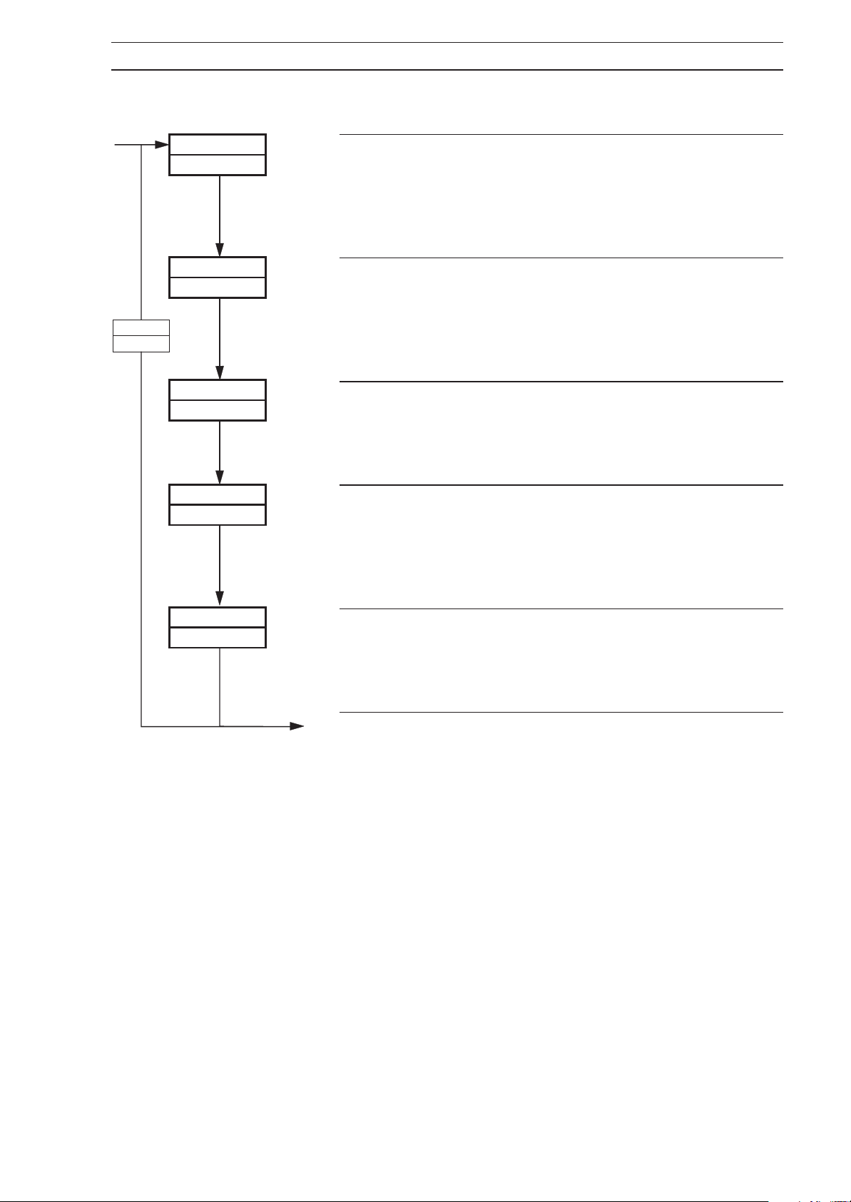
…4.2 Set Points Page
4 CONFIGURATION…
dUAL
NONE
rSP–LO
r–AdJ
rAtIO
1.000
b–AdJ
no
0
no
Remote Set Point Low Limit
This is the minimum value to which the Remote set point
can be adjusted.
Select the value required. The decimal point position is set
automatically.
Remote Set Point Ratio Adjust Enable
This frame enables or disables the display and adjustment
of the remote set point ratio in the Operating Page (see
Section 5.2 of the Operating Guide
Select
Remote Set Point Ratio
This is a scaling factor, i.e. it multiplies the remote set point
input by the ratio value set. Set the required remote set
point ratio between 0.010 and 9.999 in 0.001 increments.
Remote Set Point Bias Adjust Enable
This frame enables or disables the display and adjustment
of the remote set point bias in the Operating Page (see
Section 5.2 of the Operating Guide
Select
YES to enable or no to disable.
YES to enable or no to disable.
).
).
bIAS
0
Remote Set Point Bias
This is an offset value set as a proportion of display span
(may be ± the span value).
Set the remote set point bias in engineering units.
Continued on next page.
9
Page 12
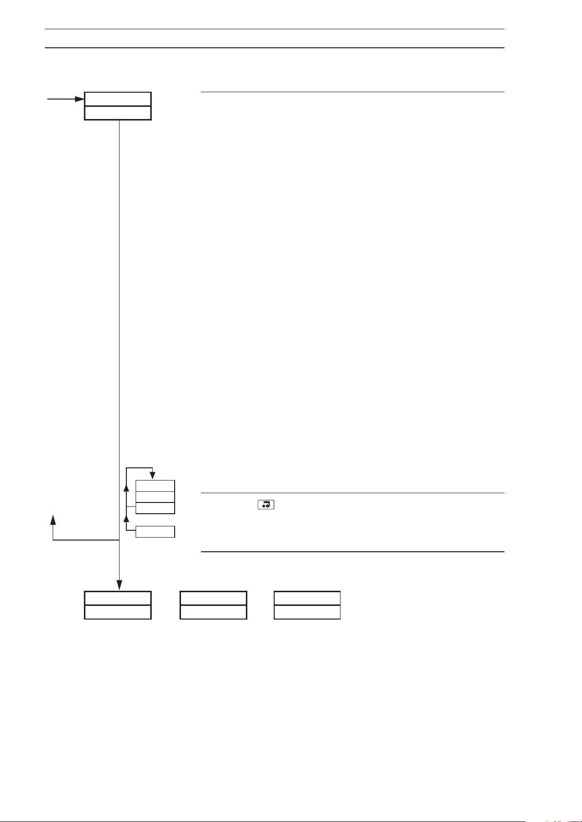
…4 CONFIGURATION
…4.2 Set Points Page
– – – – – –
– – – – – –
Set Point Type Selection
This frame displays the current set point type, or
and value – see Set Point Type Selection frame in the
Operating Page – see
Upper Display – displays the set point type, or bALNCE:
Section 5.2 of the Operating Guide
bALNCE
LOCAL – Local set point
bALNCE – Balance, the difference between the
Local and Remote (or Dual) set point
values
rEMOtE – Remote set point on controllers with
Remote set point facility
dUAL – Dual set point
Lower Display – displays the value of the set point type
shown in the upper display, but if the set point type is
changed from Local to Remote (or Dual) the display shows
the difference (
value and the Remote (or Dual) set point value.
bALNCE) between the Local set point
.
SEt UP
PrCESS
LOCAL
bALNCE
rEMOtE
or
dUAL
or
When Remote set point is selected and if Remote set point
tracking is enabled, the Local set point value tracks the
Remote set point value. The Local set point limits do not
apply in this mode. If the Local set point is outside of its
limits when Local set point type is re-selected, it can only
be adjusted towards its limits. Once within these limits,
they apply as normal.
Press to select LOCAL, bALNCE, rEMOtE (or
dUAL). rEMOtE and dUAL are dependent on the
selection made at
Return to the top of the Set Points Page or advance to the
next page.
POStn
or
F–bACK
the Second Set Point Type parameter.
rEGLtr
dAtA
10
Page 13
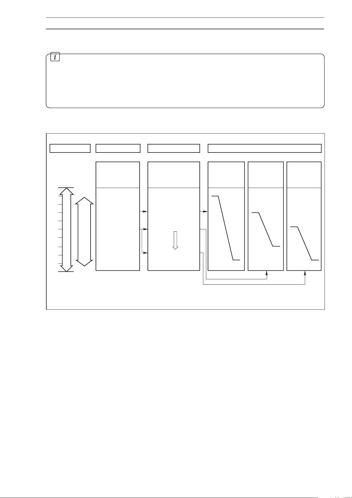
4 CONFIGURATION…
4.3 Motorized V alve Control
Information.
• Motorized valve control with or without feedback – position-proportioning (with
feedback) or boundless (without feedback).
• Ratio and bias settings can be applied to adjust the range of valve travel (positionproportioning only).
• Deadband setting – adjustable to minimize hunting of the motorized valve.
PID Output
100
80
50
20
0
Bandwidth
Proportional
Engineering Range
Ratio Bias
Ratio Setting
(0.010 to 9.999)
A 1.0
B 0.5
C 0.5
Fig. 4.2 Position-Proportioning Schematic Diagram
Bias Setting
(within Eng. range)
A 0%
B 0%
C –25%
Valve
Travel
Limits
100%
V alve
Closed
Desired V alve Position
Valve
Tra vel
Limits
V alve
Open
75%
50%
25%
0%
AB
Valve
Tra vel
Limits
0%
C
11
Page 14
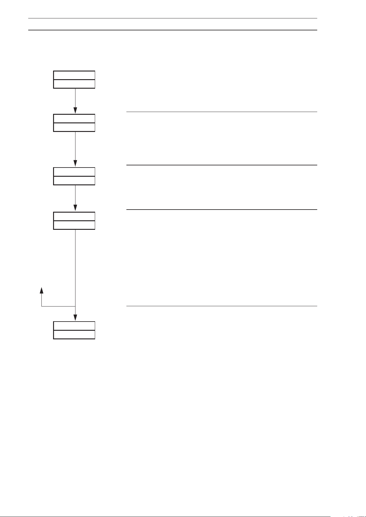
…4 CONFIGURATION
4.3.1 Position Feedback Page
This page appears only if P–PrOP is selected at the Control Type parameter in the Set Up Control
– see Fig. 3.1 and Section 4.10.
Page
POStN
F–bACK
rA tIO
1.00
bIAS
dEAdb
1.0
Page Header –
Ratio
Ratio is a scaling factor, i.e. it multiplies the position
feedback input by the value set here.
Set the required feedback ratio between 0.0 and 9.99 in
0.01 increments.
Bias
0
Bias is an offset as a percentage of the valve travel.
Set the required feedback bias between –100.0 and
+100.0%.
Deadband
Deadband is set as a percentage of the position feedback
span, between 0.0 and 10.0%, to produce a deadband
around the valve control value. This gives minimum
‘hunting’ of the motorized valve.
Position Feedback Page
SEtUP
PrCESS
Example. If the valve is to be driven to the 50% open
position and the deadband is set to 4.0%, the motor stops
driving when the position feedback is 48%. In this
example, the deadband is between 48% and 52%.
Return to the top of the Position Feedback Page or advance
to next page.
12
Page 15
4 CONFIGURATION…
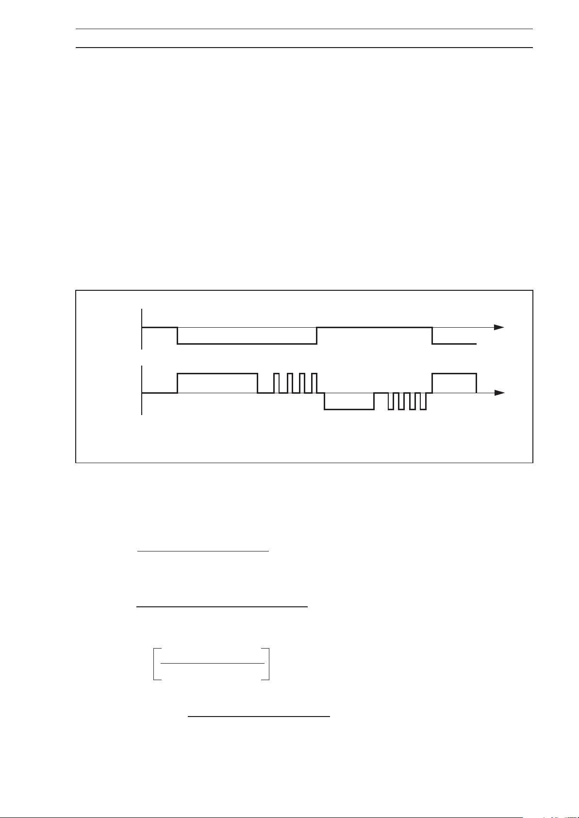
4.4 Motorized V alve Control Without Feedback (Boundless) – Fig. 4.3
A 'boundless' process controller provides an output that is effectively the time derivative of the
required regulator position, i.e. the controller signals the regulator, not where to go (position
derivative), but in which direction to travel and how far to move, by a series of integral action
pulses. Thus, the controller does not need to know the absolute regulator position and is
unaffected when the regulator reaches the upper or lower limit, as determined by the
regulator's limit switches (giving rise to the term 'boundless').
In this system, the final regulator must act as an integrator, integrating both the raise and lower
pulses in direction and duration so that the final position of the regulator reproduces the
required 2- or 3-term control function. The regulator must remain stationary indefinitely in the
absence of raise or lower commands.
When a deviation from set point is introduced, the regulator is driven for a length of time
equivalent to the proportional step. The regulator is then driven by integral action pulses until
the deviation is within the deadband setting.
+
Control
Deviation
–
Raise
Lower
Proportional
Step
Fig. 4.3 Boundless Control Action
Integral
Action Pulses
Proportional
Step
Proportional
Step
Integral
Action Pulses
Time
Time
4.4.1 Calculation for Control Pulses,
Steps and Deviation (Boundless Control only)
Minimum 'ON' time of integral action pulses (for a fixed control deviation).
Travel Time x Deadband %
=
% Proportional Band
Approximate minimum time between integral action pulses (for a fixed control deviation)
(in seconds)
Integral Action Time x Deadband %
=
2 x % Control Deviation
Duration of the proportional step
= 2 x
% Control Deviation
% Proportional Band
% Control Deviation =
Set Point – Process Variable
(in seconds)
x Travel Time in Seconds
Span
13
Page 16
…4 CONFIGURATION
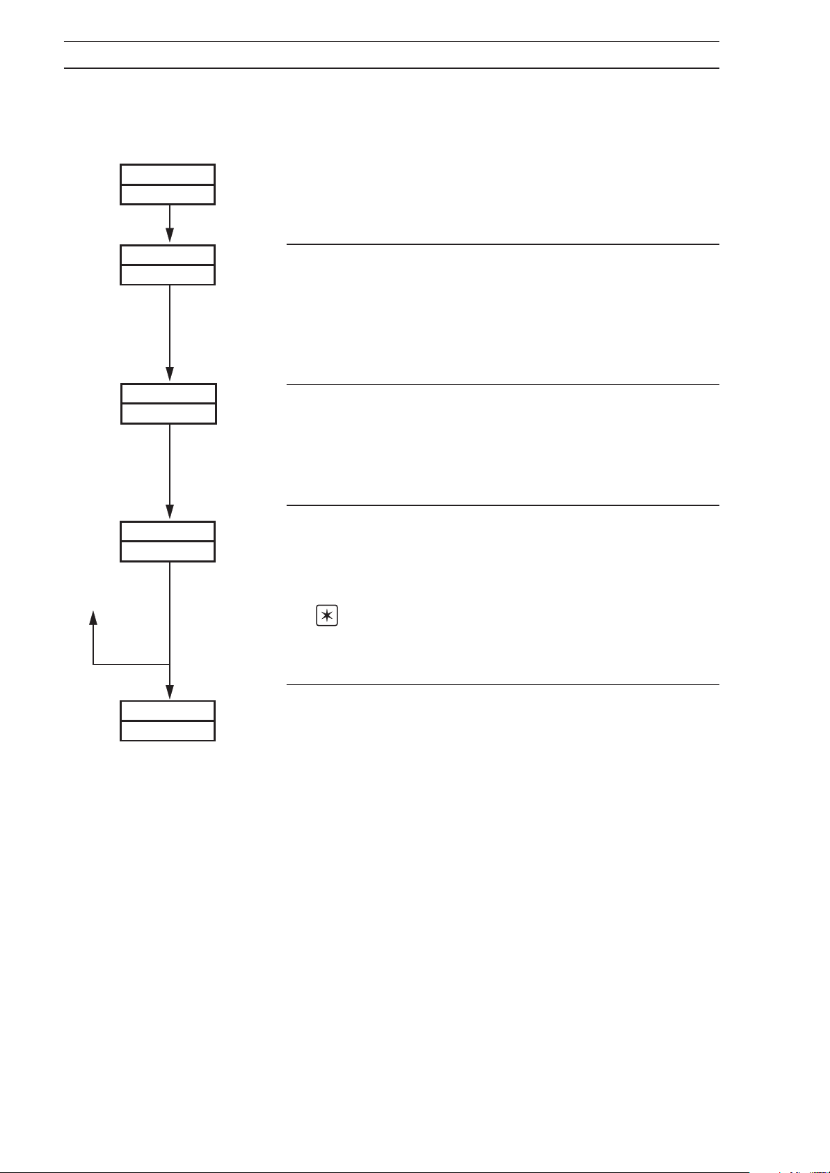
4.4.2 Regulator Data Page
This page is displayed only when bndLESS is selected at the Control Type frame in the Set Up
Control Page
– see Fig. 3.1 and Section 4.10.
rEGLtr
dAtA
rGL–t
600
dEAdb
1.0
PSN–Fb
INdCtN
Page Header – Regulator Data
Regulator Travel Time
This is the time set for the regulator to travel from the fully
open to the fully closed position or from the fully closed to
the fully open position.
Set the value required in seconds, between 1 and 5000
seconds.
Deadband Setting
The deadband is set as a percentage of the engineering
range span to produce a deadband around the control set
point value. This reduces ‘hunting’ of the regulator.
Set the required value, between 0.0 and 10.0%.
Position Feedback Indication Enable
Select
Operating Page – see
Select
INdCtN to enable the Valve Position frame in the
Section 5.2 of the Operating Guide
NONE to disable the Valve Position frame.
.
SEtUP
PrCESS
Note. A value is only displayed in the Valve Position
frame if the frame is enabled and the regulator has a
feedback signal.
Return to top of Regulator Data Page,
or
Advance to Set Up Process Variable Input Page.
14
Page 17
4 CONFIGURATION…
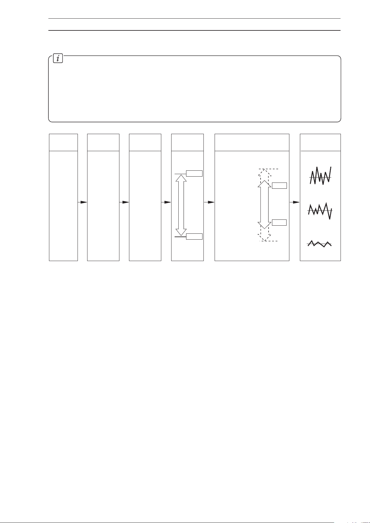
4.5 Set Up Process V ariable
Information.
• Universal inputs – mV, mA, V, T/C, RTD and resistance.
• Internal cold junction compensation.
• Linearization of temperature sensors to allow use of non-linearizing transmitters or any
electrical input.
• Programmable fault levels and actions.
• Digital filter reduces the effect of noise on inputs.
Input
Type
RTD
T/C
Current
Voltage
Millivolts
Linearizer
Type
5/2
3/2
√
RTD
T/C N
T/C B
T/C E
T/C J
T/C T
T/C S
T/C R
T/C K
None
Linearizer
Units
°F
°C
Linearizer
Range
200
0
Display Range
Fault
Detection
Level 10 %
Fault
Detection
Level 10 %
Display Range
High
220
200
0
–20
Display Range
Low
Value set to 0
Value set low
Value set high
Example – Type K thermocouple, range 0 to 200°F with 10% fault detection levels.
Program
Filter
15
Page 18
…4 CONFIGURATION
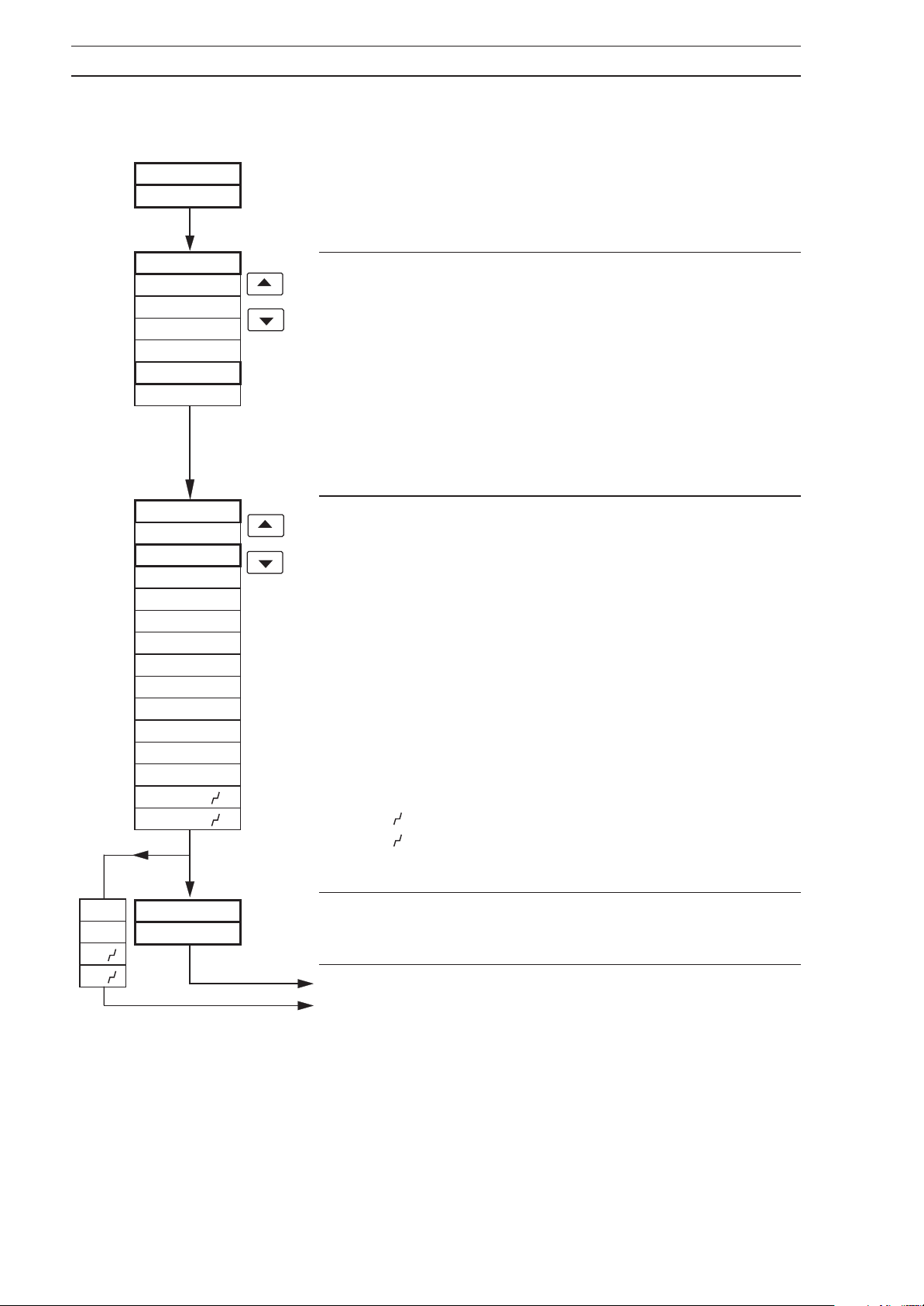
4.5.1 Set Up Process V ariable Input Page
SEtUP
PrCESS
IntYPI
U.Lt
MAMP
VOLt
ohM
tCPL
rtd
LNtYPI
NONE
tC-K
tC-r
tC-S
tC-t
tC-J
tC-L
tC-E
tC-b
tC-N
rtd
SQrt
3 2
5 2
Page Header – Set Up Process Variable Input.
Process Variable Input Type
Select the input type required:
MU.Lt – Millivolt (≤2000 mV)
MAMP – Current
V.OLt – Voltage
ohM – Resistance
tCPL – Thermocouple *
rtd – Resistance thermometer
*For thermocouple applications using an external fixed
cold junction, select millivolt input type.
Linearizer Type
Select the linearizer type required:
NONE – No linearizer
tC-K – Type K thermocouple
tC-r – Type R thermocouple
tC-S – Type S thermocouple
tC-t – Type T thermocouple
tC-J – Type J thermocouple
tC-L – Type L thermocouple
tC-E – Type E thermocouple
tC-b – Type B thermocouple
tC-N – Type N thermocouple
rtd – Resistance thermometer
SQrt – Square root
3 2 –x
5 2 –x
3/2
5/2
16
NONE
SQrt
3 2
5 2
L–UNtI
dEG C
Linearizer Units
Select the temperature units required, °C or °F.
Continued on next page.
(a)
Continued on page 18.
(b)
Page 19
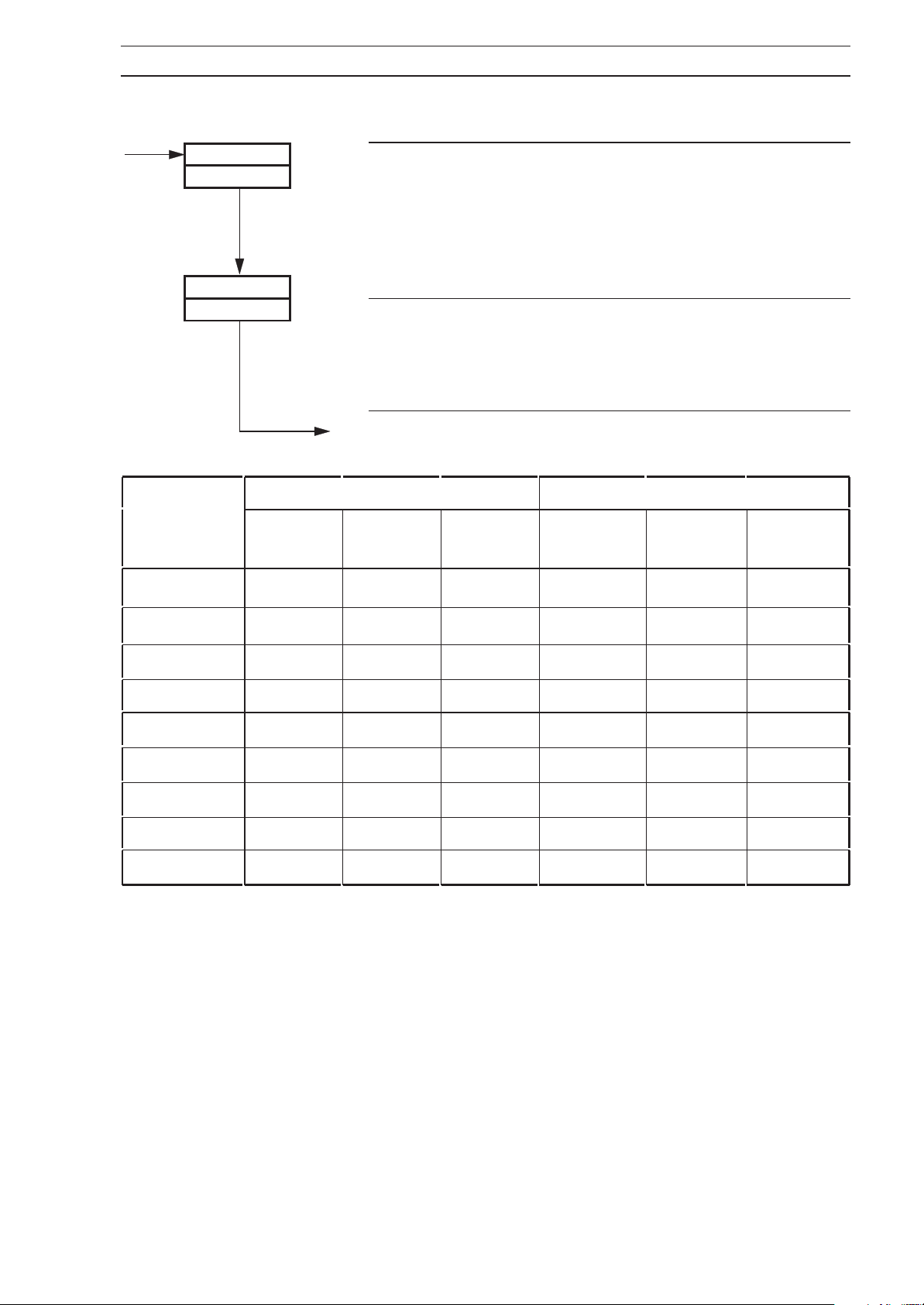
…4.5.1 Set Up Process V ariable Input Page
4 CONFIGURATION…
(a)
LIN–HI
I000
Linearizer Full Scale
Set the range maximum temperature in °C or °F as
selected at
in Table 4.1
Linearizer Units above, within the limits detailed
. If these limits are exceeded, LIN–Or
(linearizer overrange) is displayed in the Operating Page –
Table 5.1a of the Operating Guide
see
.
LIN–LO
0
(c)
Degrees Celsius Degrees Fahrenheit
(T/C) / RTD
Type
Type B* – 18 1800 710 0 3272 1278
Min. Max. Min. Span Min. Max. Min. Span
Linearizer Zero
Set the range minimum temperature in °C or °F as selected
at Linearizer Units above, within the limits detailed in Table
4.1
.
Continued on next page.
Type E – 100 900 45 – 148 1652 81
Type J – 100 900 50 – 148 1652 90
Type K – 100 1300 65 – 148 2372 117
Type L – 100 900 50 – 148 1652 90
Type N – 200 1300 90 – 328 2372 162
Type R & S* – 18 1700 320 0 3092 576
Type T – 250 300 60 – 418 572 108
RTD – 200 600 25 – 328 1112 45
* Accuracy for types B, R and S is not guaranteed below 400°C.
Minimum span below zero Type T 70°C/126°F
T/C standard DIN 43710 IEC 584
RTD standard DIN 43760 IEC 751
Table 4.1 Temperature Limits
17
Page 20
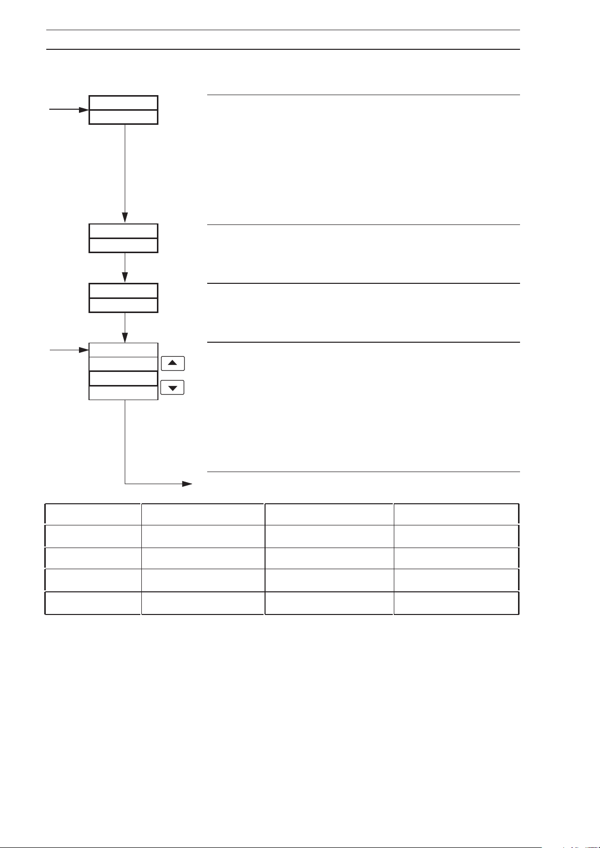
…4 CONFIGURATION
…4.5.1 Set Up Process V ariable Input Page
(b) from page 16
r–HI–I
1000
Input Range Full Scale
Set the input range maximum in electrical units,
limits detailed in Table 4.2.
within the
(c) from
page 17
dEC–Pt
1000
r–LO–I
bSPd
NONE
0
UP
dN
Example
200 in the input full scale display and advance to decimal
point display. Set the decimal point to one place to give a
value of 20.0.
Decimal Point
Set the decimal point position required for both the range
full scale and range zero values.
Input Range Zero
Set the input range minimum in electrical units,
limits detailed in Table 4.2
Broken Sensor Protection Drive
In the event of a fault being detected on the input, the
process variable is driven in the direction of the mode
selected.
Select the broken sensor drive required:
. To set an input range full scale of 20mA, enter
within the
.
NONE – No drive
UP – Upscale drive
dN – Downscale drive.
Continued on next page.
Input Type Min. Start Max. Value Min. Span
Millivolts – 2000 2000 2.5
Volts – 20 20 0.25
Milliamps – 100 100 0.25
Resistance 0 8000 10
Table 4.2 Electrical Limits
18
Page 21
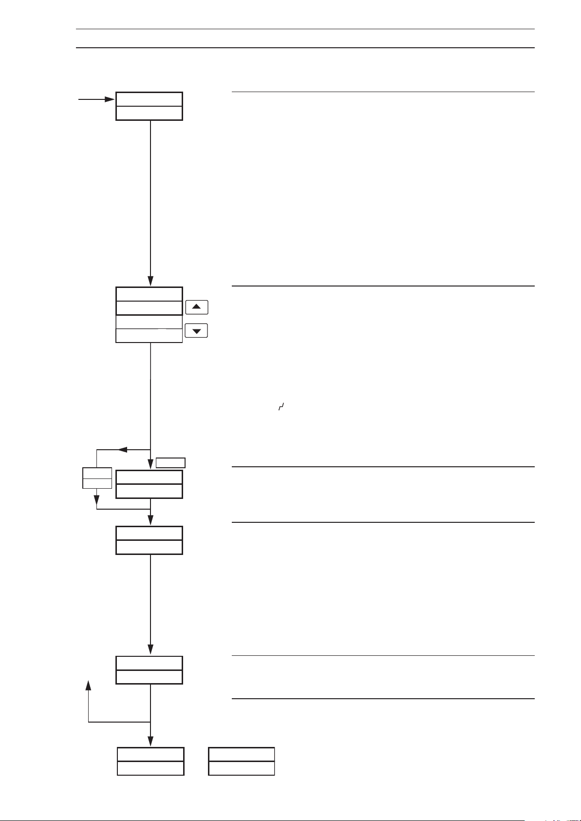
…4.5.1 Set Up Process V ariable Input Page
4 CONFIGURATION…
NONE
HOLd
FdLP–I
10.0
dEFACt
NONE
HOLd
OPP
OPP
dEF–OP
0.0
Fault Detection Level Percentage, Process Variable
Input
A fault level percentage can be set to detect a deviation
above or below the display limits. E.g. if set at 10.0%, then
if an input goes more than 10% above full scale value or
more than 10% below zero value, a fault is detected.
On some ranges the input circuitry may saturate before the
fault level set is reached. In this case an error is detected at
a level below that which is set.
Control actions and control outputs in the event of a fault
are programmable – see below.
Set the value required, between 0.0 and 100.0% in 0.1%
increments.
Default Control Action
Select the default control action required in the event of a
fault:
NONE – No default action.
HOLd – The controller reverts to Manual mode
when an error is detected. The control
output is held at the value existing
when the error was detected.
O P – The controller reverts to Manual mode
when an error is detected and the
control output value changes to the
Default Control Output value following.
Default Control Output
Set the default output value required in the event of a fault,
between 0.0 and 100.0%.
PrGFLt
0
FILtEr
– – Hrt
SEtUP
or
rSPt PAGE
dISPL
Y
Programmable Filter
This filters the process variable input, i.e. if the input is
stepped, it smooths the transition between steps and may
also be used for some degree of cleaning of noisy inputs.
The filter time represents the time a step in the input takes
to change the displayed process variable from 10 to 90%
of the step.
Set value required, between 0 and 60 in 1-second
increments.
Mains Power Filter
Set the frequency of the power supply used (50 or 60Hz).
Return to top of Process Variable Input Page or advance to
next program page.
19
Page 22
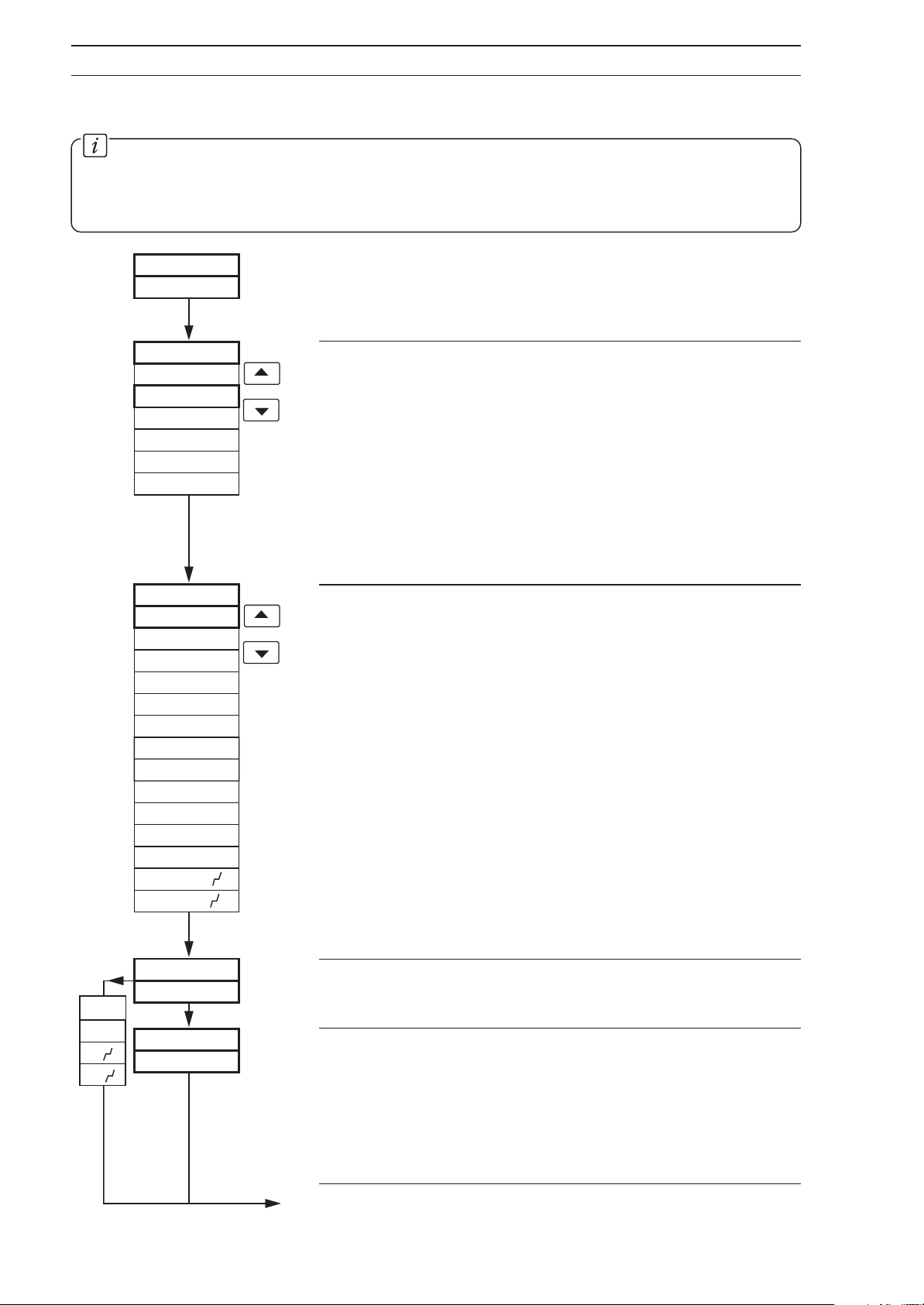
…4 CONFIGURATION
4.6 Set Up Remote Set Point Page
Information.
• This page is omitted if Remote set point is not selected at Second Set Point Type in Set
Points Page – see Section 4.2.
• Universal Input.
SEtUP
rSPt
INtYP2
MVLt
MAMP
VOLt
ohM
tCPL
rtd
LNtYP2
NONE
tC-K
tC-r
tC-S
tC-t
tC-J
tC-L
tC-E
tC-b
tC-N
rtd
SQrt
3 2
5 2
Page Header – Set Up Remote Set Point Input.
Remote Set Point Input Type
Select the input type required:
MVLt – Millivot (≤2000mV)
MAMP – Current
VOLt – Voltage
ohM – Resistance
tCPL – Thermocouple*
rtd – Resistance thermometer
*For thermocouple applications using an external fixed
cold junction, select millivolt input type.
Remote Set Point Linearizer Type
Select the linearizer type required:
NONE – No linearizer
tC-K – Type K thermocouple
tC-r – Type R thermocouple
tC-S – Type S thermocouple
tC-t – Type T thermocouple
tC-J – Type J thermocouple
tC-L – Type L thermocouple
tC-E – Type E thermocouple
tC-b – Type B thermocouple
tC-N – Type N thermocouple
rtd – Resistance thermometer
SQrt – Square root
3/2 –x
5/2 –x
3/2
5/2
NONE
SQrt
20
3 2
5 2
L–UNt2
dEG C
LIN–HI
I000
Linearizer Units
Select the temperature units required, °C or °F.
Linearizer Full Scale
Set the range maximum temperature in °C or °F as
selected at
in Table 4.1. If limits are exceeded,
overrange) is displayed in the
5.1a of the Operating Guide
Continued on next page.
Linearizer Units above, within the limits detailed
LIN–Or (linearizer
Operating Page – see
.
Table
Page 23
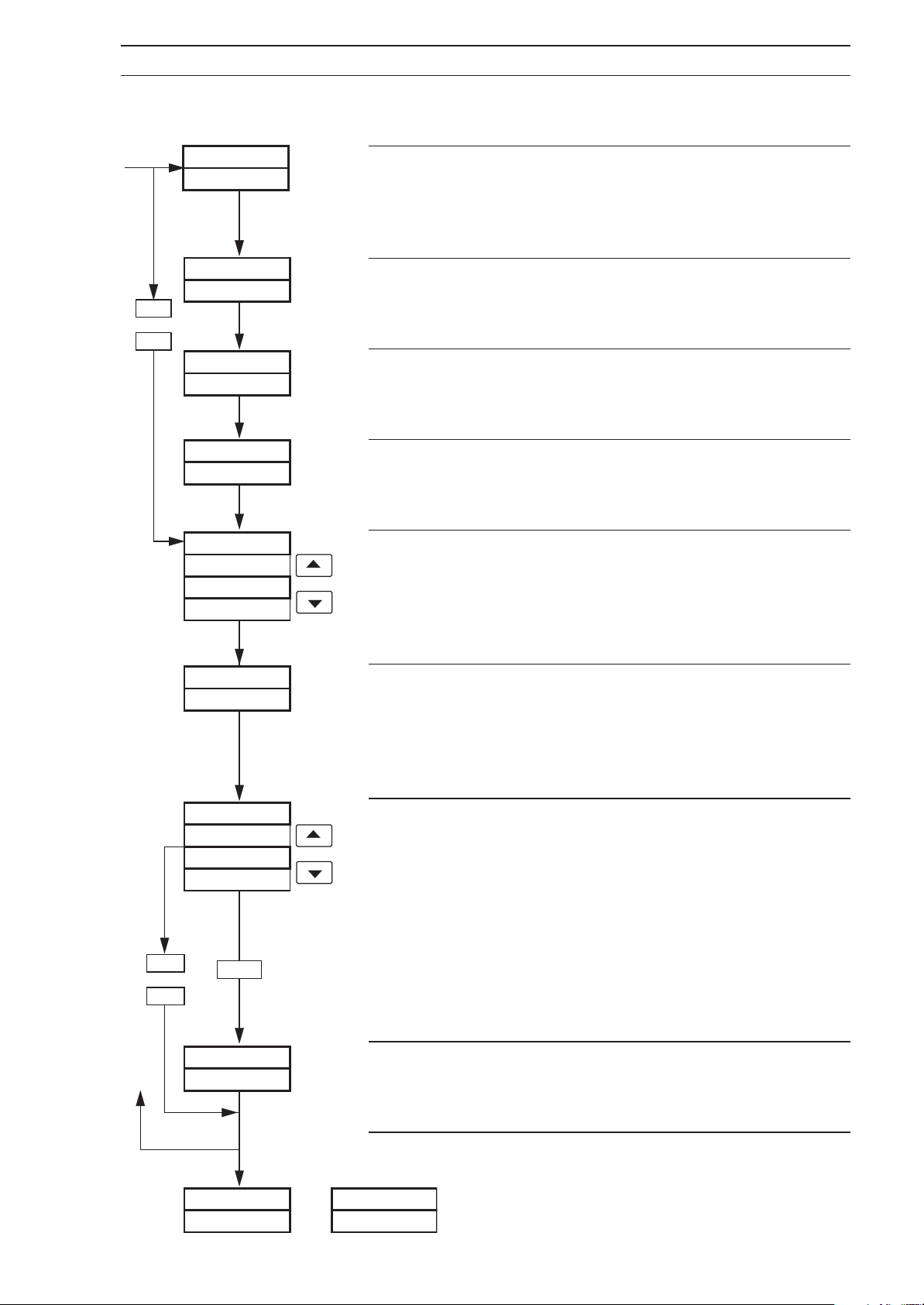
…4.6 Set Up Remote Set Point Input Page
4 CONFIGURATION…
rtd
or
tc–x
LIN–LO
r–HI–2
20.0
dEC–Pt
20.0
r–LO–2
4.0
bSPd– 2
NONE
UP
dN
Linearizer Zero
0
Set the range minimum temperature in °C or °F as selected
at
Linearizer Units above, within the limits detailed in Table
4.1.
Remote Set Point Range Full Scale
Set the remote set point range full scale value within the
limits in
Decimal Point
Set the decimal point position required for
full scale and range zero values.
Input Range Zero
Set the remote set point range zero value required within
the limits in
Broken Sensor Protection Drive
In the event of a fault being detected on the input, the
remote set point is driven according to the Broken Sensor
Protection Drive. Select the drive required:
drive,
Table 4.2 – see page 18.
both the range
Table 4.2 – see page 18.
NONE for no
UP for upscale drive or dN for downscale drive.
NONE
or
LOCAL
FdLP–2
10.0
dEFACt
NONE
LOCAL
dF–SP
dF-SPt
dEF–SPt
500.0
Fault Detection Level Percentage, Remote Set Point
This frame is as described in the
Percentage, Process Variable Input
Set the value required, between 0.0 and 100.0% in 0.1%
increments.
Default Action (Remote Set Point)
Select the default action required in the event of an error:
Fault Detection Level
frame – see page 19.
NONE – No default action.
t
LOCAL – The controller reverts to local mode
when an error is detected and the local
set point value is used.
dF–SPt – The controller reverts to local mode
when an error is detected and the set
point value changes to the Default Set
value below.
Point
Default Set Point
Set the default set point value required in the event of an
error.
or
SEtUPdISPLY
PAGE PSN–Fb
Return to top of Remote Set Point Input Page or advance to
the next programming page.
21
Page 24
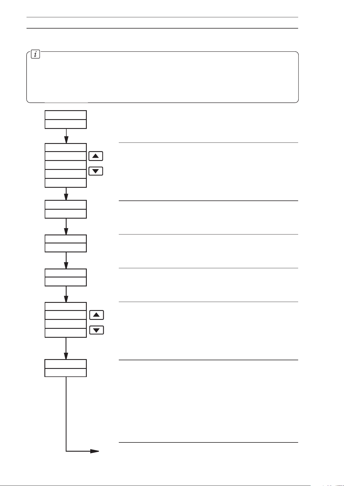
…4 CONFIGURATION
4.7 Set Up Position Feedback Page
Information.
• This page is only present if
Up Control Page – see Fig. 3.1 and Section 4.10. If
Feedback Enable must be set to
• Millivolt, current, voltage or resistance input.
• Programmable fault level and actions.
P–PrOP or bndLSS is selected at Control Type in the Set
INdCtN to enable access to this page.
bndLSS is selected, Position
SEtUP
PSN–Fb
IntYP3
MVLt
MAMP
VOLt
ohM
r–HI–3
135.0
dEC–Pt
135.0
r–LO–3
0.0
Page Header – Set Up Position Feedback.
Position Feedback Input Type
Select the input type required:
MVLt – Millivolt ≤2000mV
MAMP – Current
VOLt – Voltage
ohM – Resistance
Position Feedback Range Full Scale
Set the position feedback range full scale value, within the
limits of Table 4.2 – see page 18.
Decimal Point Position
Set the decimal point position required for both the position
feedback range full scale and range zero values.
Position Feedback Range Zero
Set the position feedback range zero value, within the
limits of Table 4.2 – see page 18.
22
bSPd– 3
NONE
UP
dN
FdLP–3
10.0
Broken Sensor Protection Drive
In the event of a fault being detected on the input, the
remote set point is driven in the direction of the mode
selected.
Select the broken sensor drive required: NONE for no
drive,
Fault Detection Level Percentage, Position Feedback
Input
A fault level percentage can be set to detect a deviation
above or below the display limits. E.g. if set to 10.0%, then
if the position feedback input deviates by more than 10%
above Full Scale value or 10% below zero value, a fault is
detected. Position feedback action in the event of a fault is
programmable – see
Set the value required, between 0.0 and 100.0%.
Continued on next page.
UP for upscale drive or dN for downscale drive.
Default Action.
Page 25
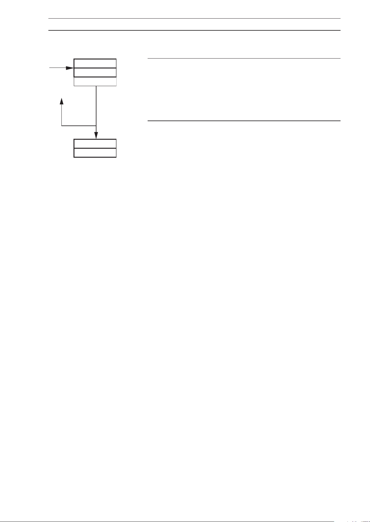
…4.7 Set Up Position Feedback Page
4 CONFIGURATION…
dEFACt
NONE
HOLd
dISPLY
PAGE
Default Action
Select the default position feedback action required:
NONE – No default action
HOLd – The controller reverts to Manual mode and
holds the valve position existing when the
fault was detected.
Return to top of Set Up Position Feedback Input Page.
or
Advance to Set Up Display Page.
23
Page 26
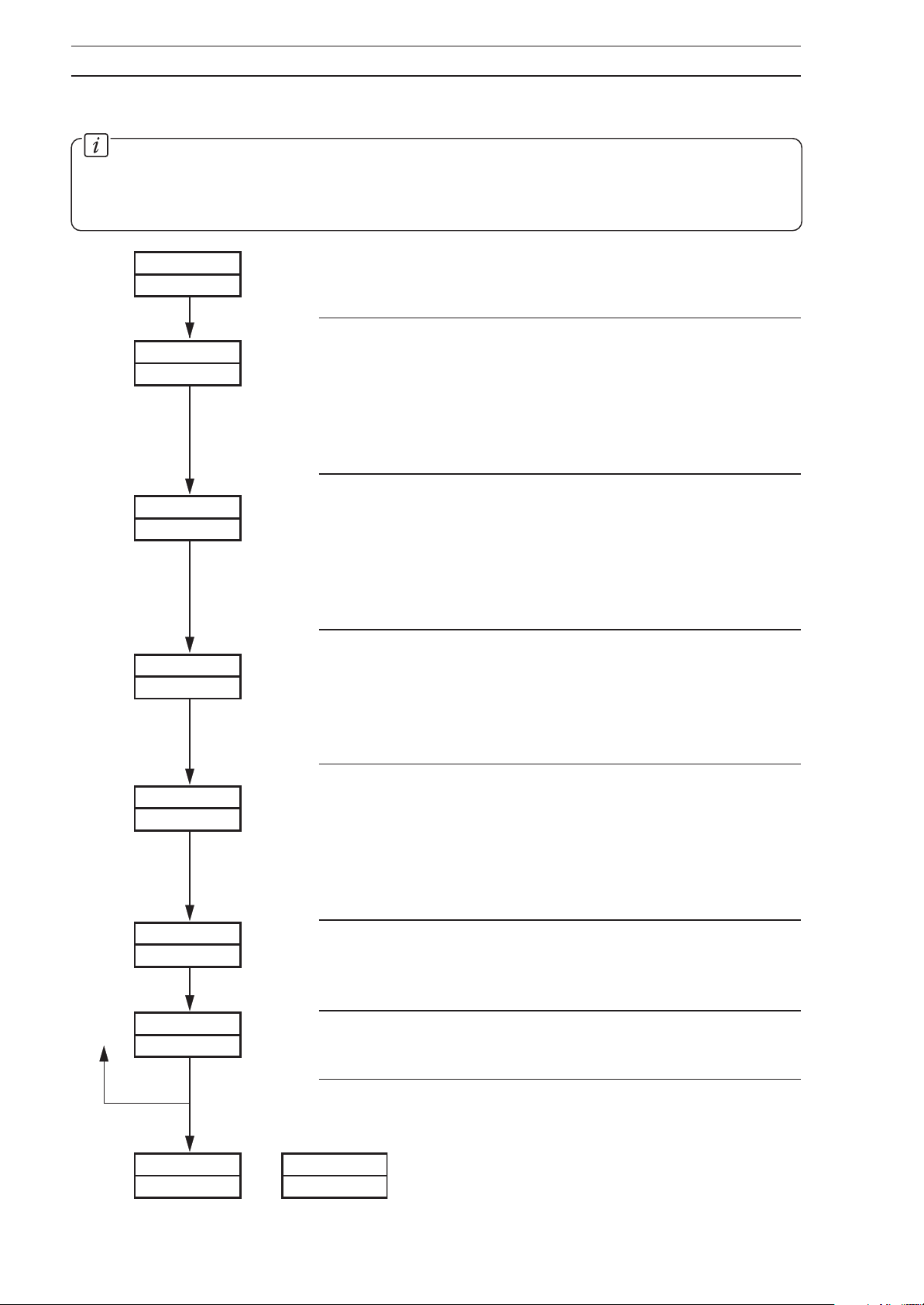
…4 CONFIGURATION
4.8 Set Up Display Page
Information.
• Set up engineering ranges and units.
• Programmable increments on deviation bargraph.
• Adjust display brightness.
Page header – Display Page.
dISPLY
PAGE
Display Full Scale
dIS–HI
1000
dEC–Pt
1000
Set the display value which represents the maximum
process variable input signal, between –9999 and +9999.
Example – For an input range of 4 to 20mA representing a
pressure range of 50 to 250 bar, set 2500. The decimal
point position is set at the next parameter.
Decimal Point Position
Set the required number of decimal places for both the
display full scale and display zero values. In the example
shown above, set the decimal point position to show
increments of 0.1 bar, i.e. 250.0.
dIS–LO
INCMNt
UNItS
dEG C
brIGHt
7
0
1
Display Zero
Set the display value which represents the minimum
process variable input signal, between –9999 and +9999.
In the example shown above, set 50.0. The decimal point
position is set automatically.
Percentage Increment Per Bar (Bargraph)
This frame sets the percentage deviation from set point
that each bar of the Deviation Bargraph represents – see
Fig. 4.1 in the Operating Guide
Set the value required, between 1 and 10% of display
span.
Display Units
Select the required display units,
to represent the process variable.
Brightness Adjustment
Select the required display brightness between 4 and 10.
.
dEG C, dEG F, or NONE
24
SEtUP
or
Return to top of Display Page or advance to the next
programming page.
C–PrOP
OUtPUtCONtrL
Page 27
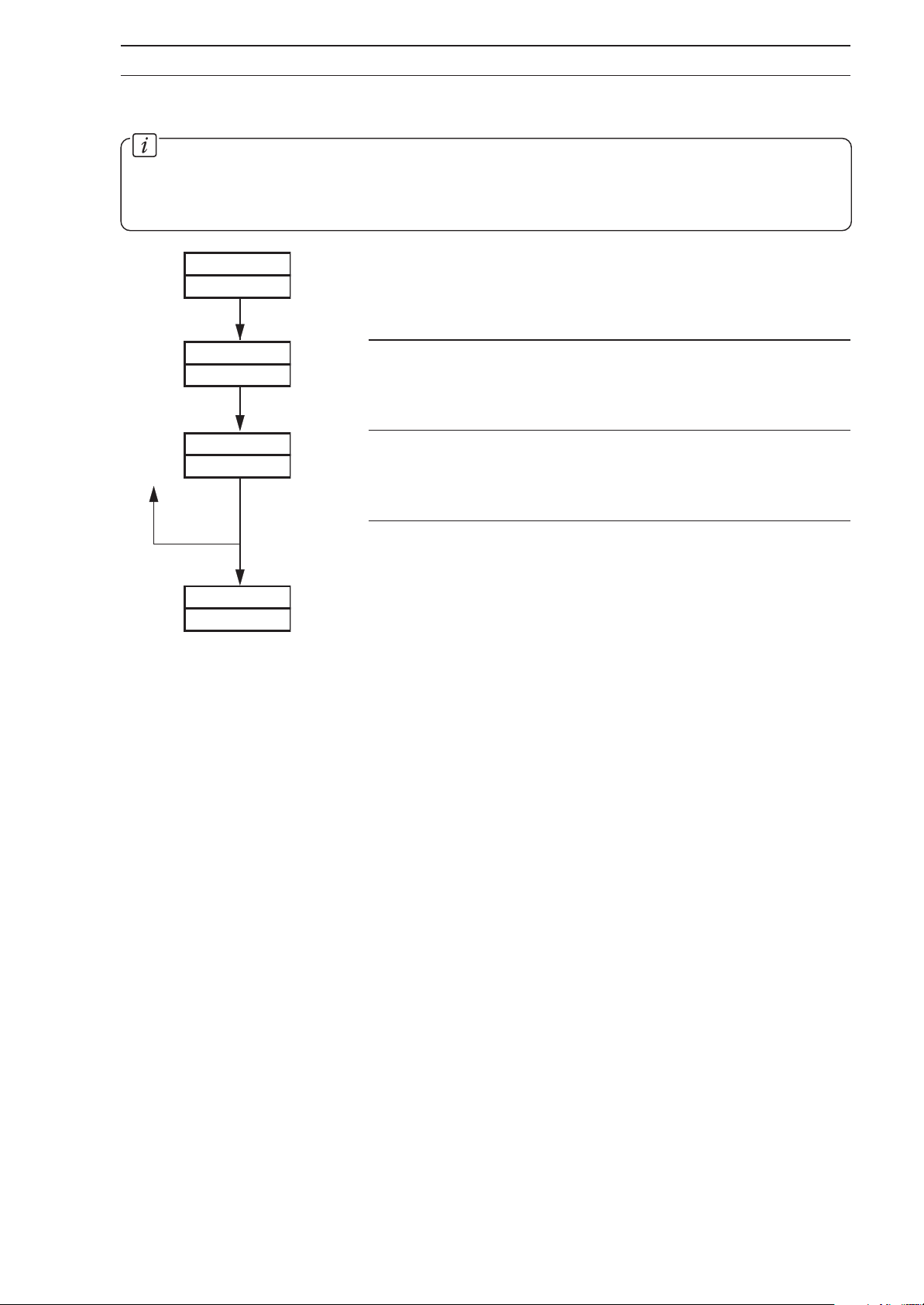
4.9 Current Proportioning Output Page
Information.
• This page is only present when
Control Page
• Programmable current control output range.
– see Fig. 3.1 and Section 4.10.
C–PrOP is selected at Control Type frame in Set Up
4 CONFIGURATION…
C–PrOP
OUtPUt
ANL–HI
20.0
ANL–LO
4.0
SEtUP
CONtrL
Page header – Current Proportioning Output.
Current Proportioning Output Maximum
Set the maximum analog output value, between 0.0 and
20.0mA in 0.1mA increments.
Current Proportioning Output Minimum
Set the minimum analog output value, between 0.0 and
20.0mA in 0.1mA increments.
Return to top of Current Proportioning Output Page.
or
Advance to
Set Up Control Page.
25
Page 28
…4 CONFIGURATION
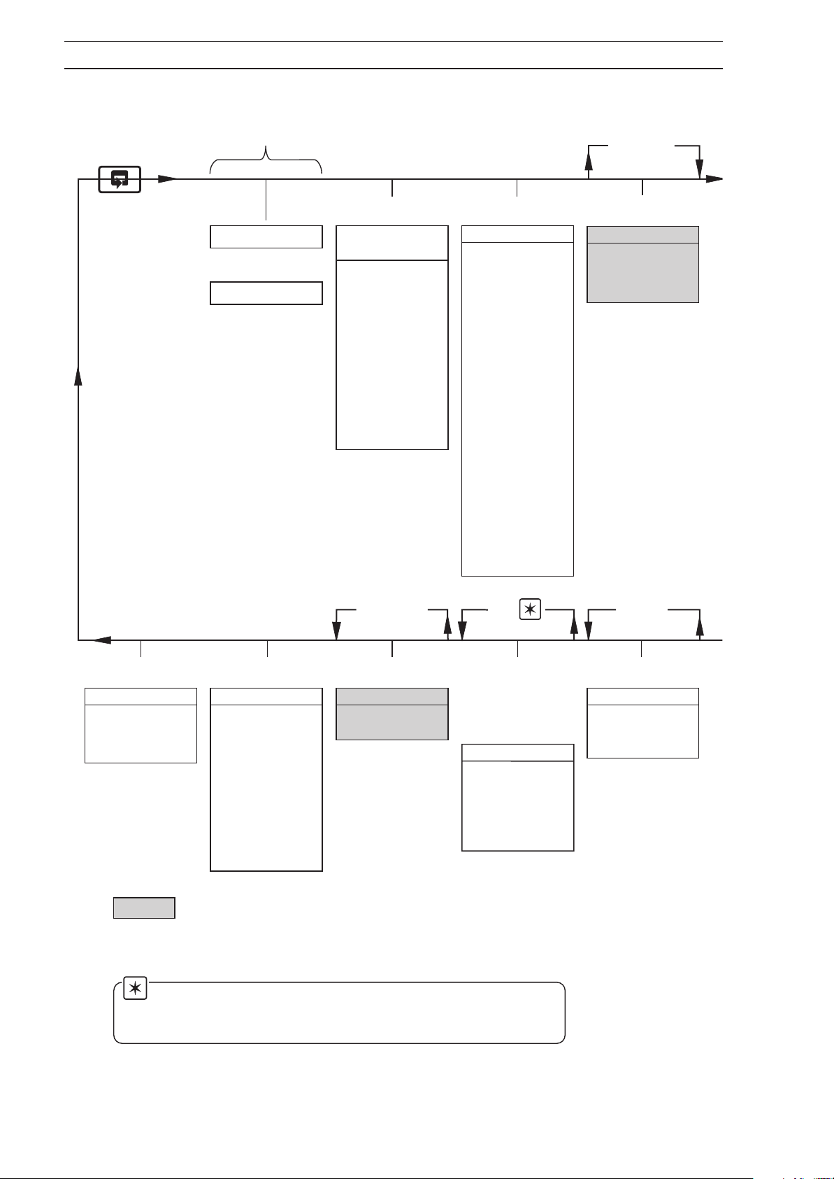
Refer to
Operating
Guide
Operating Page
To
Control Page
Section 4.1,
Page 4
Profile Program
Page
■
Profile Enable
■
Menu/Program
Select
■
Program
Start/End Levels
■
Segment
Duration
■
Segment
Start/End Levels
■
Program Repeat
■
Hysteresis
Section 4.2,
Page 6
Set Points Page
■
Local Set Point
Adj. Enable
■
Local Setpoint
High/Low Limits
■
Local Set Point
Value
■
Set Point
Tracking Enable
■
Set Point Type
Select
■
Second Set Point
Type
■
Remote Set Point
Tracking Enable
■
Second Set Point
High/Low Limits
■
Remote Set Point
Ratio/Bias Values
■
Set Point Type
Selection
If P–Prop is not
selected in
Set Up Control Page
Section 4.3.1,
Page 12
Position F-B Page
■
Ratio Value
■
Bias Value
■
Deadband Value
HtCOOL is with Time
Proportioning
Section 4.15,
Page 48
Access Page
■
Configuration
Password
■
Tuning Password
Section 4.14,
Page 45
Scale Adjust Page
■
Scale Adjust PV
Input Range
High/Low Limits
■
Scale Adjust
RSPT Range
High/Low Limits
■
Scale Adjust
Position
Feedback Range
Section 4.13,
Page 44
Cool Output Page
■
Output High/Low
Limit
Section 3.1, Page 7
of the
Communications
Option,Operating
■
Transmission
Rate
■
Controller
Identification
■
Parity
High/Low Limits
These pages are not displayed for all
Control Type selections – see Section
4.10, Control Type
frame in the Set Up
Control Page
Note. The Serial Page is always displayed on wall-/pipe-mounted
instruments and only displayed on panel-mounted instruments if a serial
board is fitted.
See
MODBUS
(RTU)
Guide
Serial Page
If
HtCOOL is with
Current
Proportioning
Section 4.12,
Page 44
Retrans. O/P Page
■
Parameter Type
■
Retrans.
High/Low Limits
26
Page 29
4 CONFIGURATION…
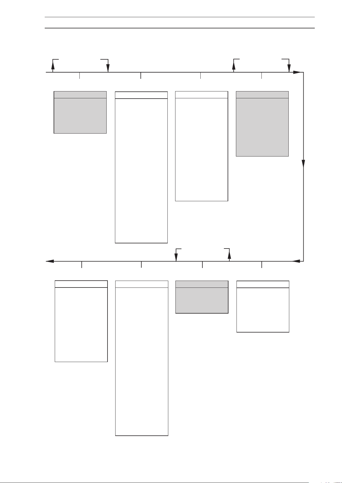
If BndlSS is not
selected in Set Up
Control Page
Section 4.4.2, Page 14
Regulator Data Page
■
Regulator Travel
Time
■
Deadband Setting
■
Position Feedback
Enable
Section 4.5.1, Page 16
Set Up PV Page
■
Process Variable
Input Type
■
Linearizer Type
■
Linearizer Units
■
Linearizer
High/Low Temp
Limits
■
Input High/Low
Limits
■
Decimal Point
■
Broken Sensor
Protection Drive
■
Fault Detection
Level % PV I/P
■
Default Control
Action
■
Default Output
■
Programmable
Filter
■
Mains Filter
Section 4.6, Page 20
Set Up RSPT Page
■
Remote Set Point
Input Type
■
Linearizer Type
■
Linearizer Units
■
Linearizer
High/Low Temp
Limits
■
RSPT Input
High/Low Limits
■
Decimal Point
■
Fault Detection
Level % RSPT
■
Default Action
Default Set Point
■
If C–Prop is not
selected in Set Up
Control Page
If P–Prop is not
selected in Set Up
Control Page
Section 4.7, Page 22
Set Up PFB Page
■
Position Feedback
Input Type
■
Input High/Low
Limits
■
Decimal Point
■
Fault Detection
Level % PFB I/P
■
Default Action
Section 4.11, Page 37
Set Up Alarms Page
■
Alarm Identities
■
Alarm Type
■
Trip Levels
■
Hysteresis
■
Rate Alarm Filter
■
Relay Assignments
■
Alarm Message
Enable
■
Alarm Acknowledge
Type
Section 4.10, Page 28
Set Up Control Page
■
Control Type
■
Control Mode
■
Second Output
Type
■
Power Fail Mode
■
Auto to Manual
Power Fail Output
■
Manual to Manual
Power Fail Output
■
Power Fail
Indication Enable
■
Auto/Manual
Switch Enable
■
Output High/Low
Limits
■
Control Action
■
Logic Inputs
■
Configured Output
■
Fixed Dual Set
Points
Section 4.9, Page 25
Current Output Page
■
Current
Proportioning
Output High/Low
Limits
Section 4.8, Page 24
Display Page
■
Display High/Low
Limits
■
Decimal Point
■
Bar Graph %
Increment Per Bar
■
Display Units
27
Page 30
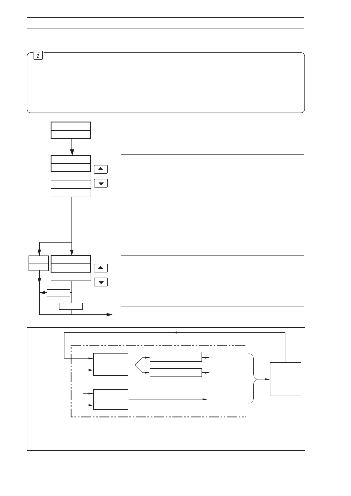
…4 CONFIGURATION
4.10 Set Up Control Page
Information.
• Control types – Current Proportioning, Time Proportioning (and On/Off), Positionproportioning (motorized valve control with feedback) and Boundless.
• Heat/cool function can be selected.
• Programmable power-up control modes and outputs.
• Reverse and direct control actions.
• High and low output limits.
P–PrOP
bNdLSS
SEtUP
CONtrL
C–tYPE
C–MOdE
SINGLE
C–PrOP
t–PrOP
P–PrOP
bNdLSS
SINGLE
HtCOOL
Page Header – Set Up Control.
Control Type
Select the control type required:
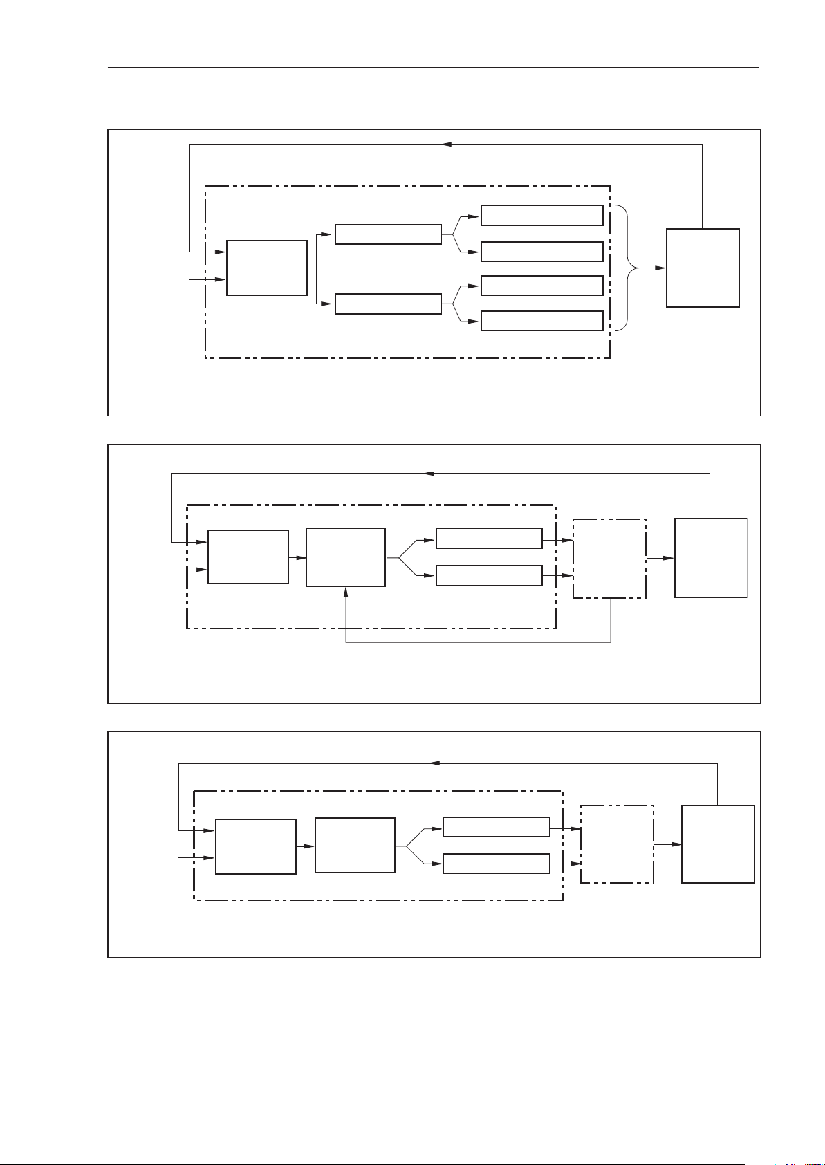
C–PrOP – current proportioning – see Fig. 4.4.
t–PrOP – time proportioning – see Fig. 4.4.
P–PrOP – position proportioning – motorized valve
with position feedback – see Fig. 4.6.
bNdLSS – boundless – motorized valve without
position feedback. If
the self-tune facility is not available and
the Self-tune Page cannot be accessed –
see Fig. 4.7.
Control Mode
Select the control mode required:
bNdLSS is selected,
SINGLE – normal control mode, used for all
applications except Heat/Cool.
HtCOOL – Heat/Cool control mode – see Fig. 4.5.
28
Process
Variable
Set Point
HtCOOL
Continued on page 30.
PID
Control
Terms
On/Off
Control
Fig. 4.4 Standard Control Schematic Diagram
Time Proportioning
Analog Output
CONTROLLER
Relay or
Digital Output
4 to 20mA
Relay or
Digital
Output
Feedback
Process
Page 31
…4.10 Set Up Control Page
Process
Variable
Set Point
PID
Control
Terms
Fig. 4.5 Heat/Cool Control Schematic Diagram
4 CONFIGURATION…
Feedback
Time Proportioning
Heat Output
Analog Output
Process
Time Proportioning
Cool Output
Analog Output
CONTROLLER
Process
Variable
Set Point
Process
Variable
Set Point
PID
Control
Terms
Fig. 4.6 Position Proportional Control Schematic Diagram
P + D
Control
Terms
Motorized
Valve
Control
CONTROLLER
Boundless
+
Integral
Open Relay
Close Relay
Position Feedback
Open Relay
Close Relay
Valve
Valve
Feedback
Process
Feedback
Process
CONTROLLER
Fig. 4.7 Boundless Control Schematic Diagram
29
Page 32
…4 CONFIGURATION
…4.10 Set Up Control Page
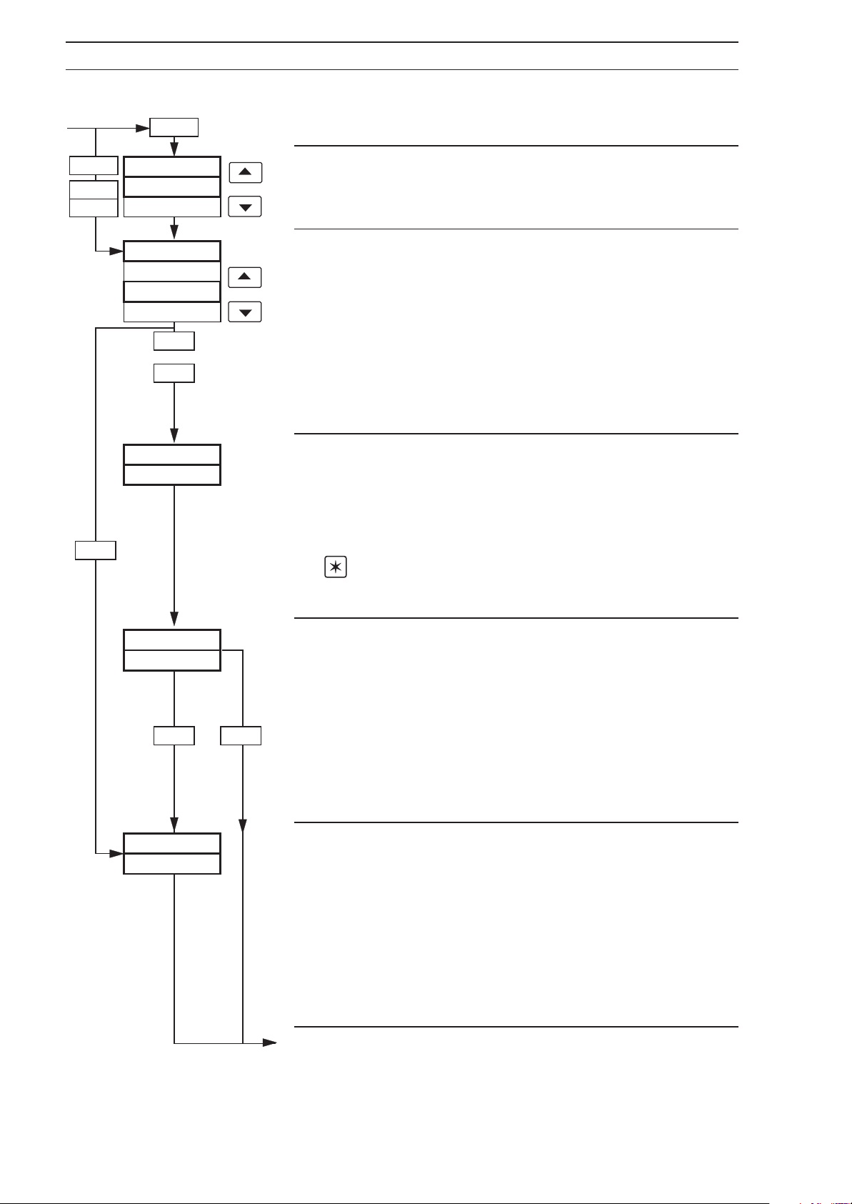
Ht-COOL
SINGLE
P–PrOP
bNdLSS
AUtO
OPtYPE
t–PrOP
PF M OdE
Aut OP
Power
Failure
Mode
C–PrOP
LASt
MANUAL
AUtO
LASt
or
MANUAL
0.0
Power
Failure
Mode
Second Output Type
Select
for analog output.
Power Failure Mode
Select the default power failure mode required following a
power interruption or failure:
t–PrOP for time proportioning output or C–PrOP
LASt – restart in the same mode existing prior
to power failure.
MANUAL – restart in Manual mode. (Not applicable
when boundless control type is
selected).
AUtO – restart in Auto mode.
Auto to Manual Power Fail Output
A control output value can be set when the power down
state is
Set the control output value required following a power
failure, between 0.0 and 100.0% in increments of 0.1%.
is set to
AUtO and the power failure mode is MANUAL.
Note. This setting has no effect if power failure mode
AUtO.
MAN OP
LASt
LASt
AMA OP
AUtO
Power
Failure
Mode
MANUAL
Manual to Manual Power Fail Output
This is the control output value required when power down
state is
Set the control output value required following a power
failure, between 0.0 and 100.0% in increments of 0.1%, or
MANUAL and power failure mode is MANUAL.
LASt.
LASt – the percentage control output
present prior to the power failure is
retained.
Auto Power Fail Output
This is the output value required when the power down
state is
Set the output value required following a power failure,
between 0.0 and 100.0% in increments of 0.1 %, or
If
AUtO is selected, normal start-up is restored on power
up. If boundless control type is selected, this parameter
must be set to AUtO.
Continued on next page.
AUtO and the power failure mode is AUtO.
AUtO.
30
Page 33
…4.10 Set Up Control Page
4 CONFIGURATION…
HEAtCL
PF–INd
no
F–MSGE
no
AUtMAN
on
Power Fail Indication Enable
If the indication is enabled,
Operating Page following a power failure.
the
Select
YES to enable or no to disable indication.
LINE FAILEd is displayed in
Failure Message
The following
enabled or disabled – see
Operating Page failure messages can be
Section 5.2 of Operating Guide
F–INPt – process input failure
F–rSPt – remote set point failure
F–POSN – position feedback failure
Select
Auto/Manual Switch Enable/Disable
Select
If HEAtCL is selected at Control Mode, advance to Control
Action (Heat)
Continued on next page.
YES to enable or no to disable.
on to enable, or OFF to disable.
, otherwise advance to Output High Limit.
.
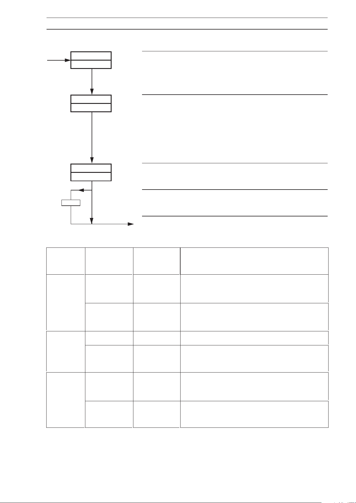
Power Fail
Mode
Auto
Manual
Last
Mode on
Power Down
Auto Auto
Manual Auto
Auto Manual Value set in Auto-to-Manual Output frame (or LAST)
Manual Manual
Auto Auto
Manual Manual
Mode on
Power Up
Control Output
(Valve Position) on Power Up
Integral component of the control output is preset to
give bumpless operation at power-up at the value set
in the Auto-to-Auto frame.
Integral component of the control output is preset to
give bumpless operation at power-up at the value set
in the Manual-to-Auto frame (or LAST)
Value set in Manual-to-Manual Output frame or
output value prior to power-down (if LAST selected)
Integral component of the control output is preset to
give bumpless operation at power-up at the value set
in the Auto-to-Auto frame (or LAST)
Value set in Manual-to-Manual Output frame or
output value prior to power-down (if LAST selected)
Table 4.3 Power-up and Power-down Control Modes
31
Page 34
…4 CONFIGURATION
…4.10 Set Up Control Page
HEAtCL
OP–HI
100.0
OP–LO
0.0
Output High Limit
This limits the high level of the control output value (or
valve position) when in Automatic mode. If the control
output is above this limit when Automatic mode is selected,
the output is allowed to stay at its current level but is not
allowed to go any higher. Once the control output returns
to, or falls below, this limit, the limit then applies. When the
controller is in Manual mode, the output limits do not apply.
Select the output high limit value (or valve position)
required, between 0.0 and 100.0% in 0.1 increments.
Output Low Limit
This limits the low level of the control output value (or valve
position) when in Automatic mode. If the control output is
below this limit when Automatic mode is selected, the
output is allowed to stay at its current level but is not
allowed to go any lower. Once the control output returns to,
or rises above, this limit, the limit then applies. When the
controller is in Manual mode, the output limits do not apply.
HEAtCL
ACtION
rEV
Select the output low limit value (or valve position)
required, between 0.0 and 100.0% in 0.1 increments.
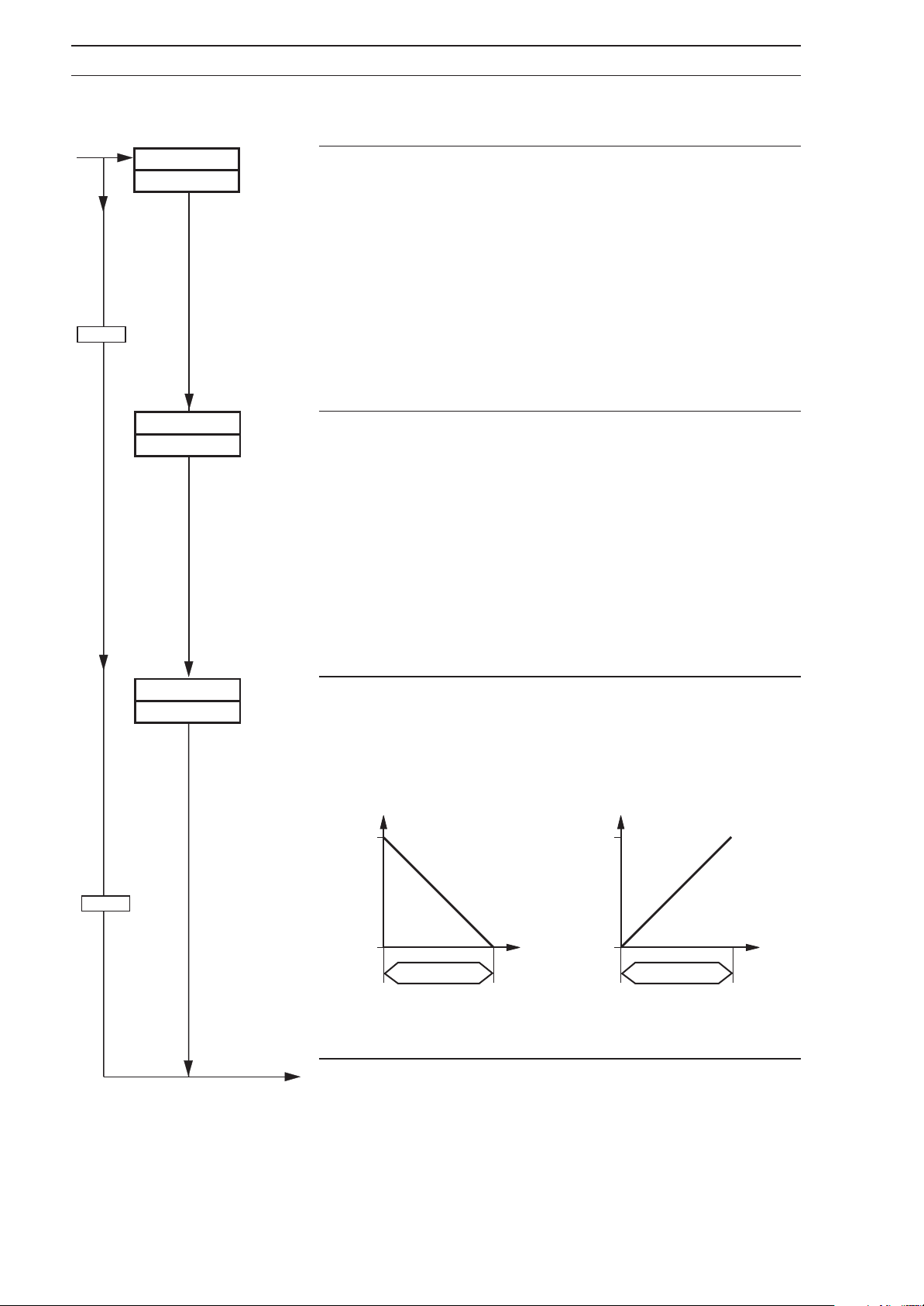
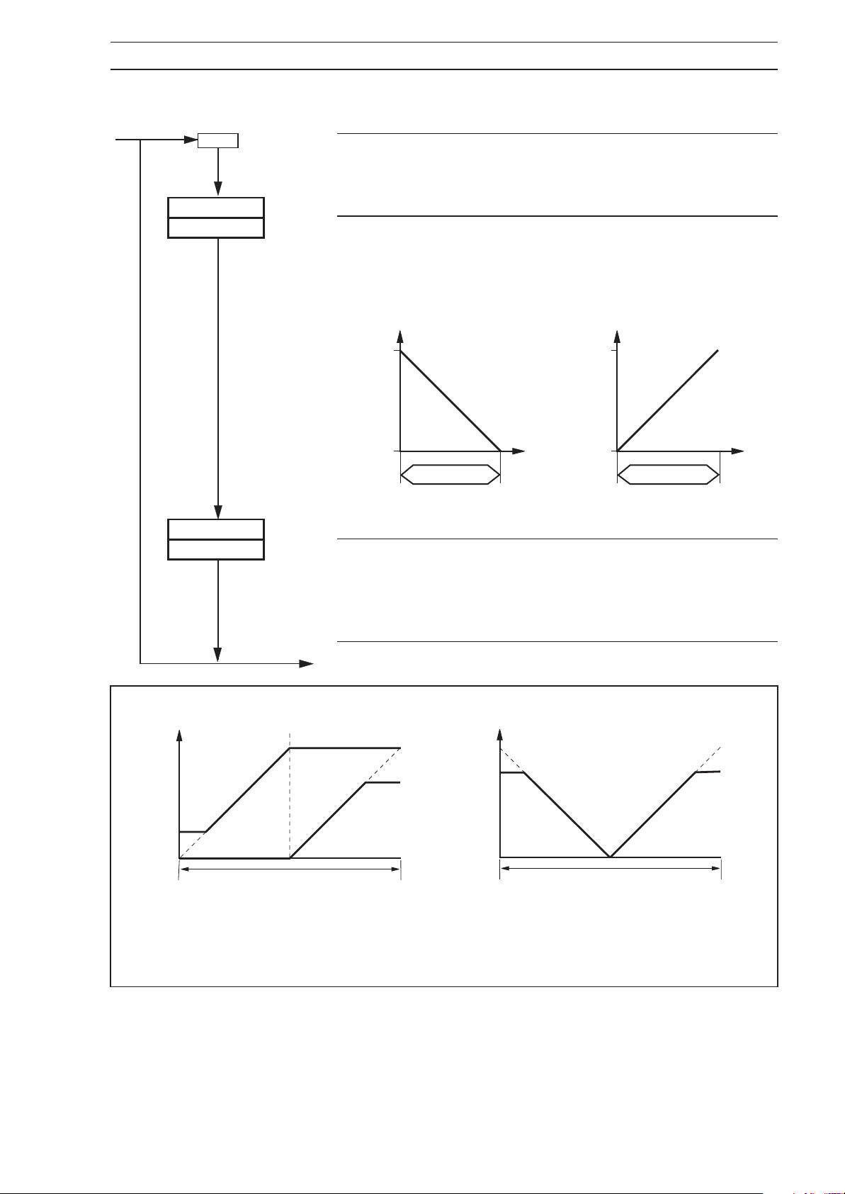
Control Action
Select the action for the PID control output:
dir – direct acting
rEV – reverse acting.
100
%
Output
0
Reverse Acting
Output
decreases
as process
variable
increases
Eng. Range
PV
100
%
Output
0
Output
increases
as process
variable
increases
Eng. Range
Direct Acting
PV
32
Continued on next page.
Page 35
…4.10 Set Up Control Page
4 CONFIGURATION…
HEAtCL
ACtN–h
rEV
ACtN–c
dir
If HEAtCL was selected at Control Mode, advance to
Control Action (Heat), otherwise advance to Logic Input
Type 1.
Control Action (Heat)
Select the action for the heat and PID control outputs:
dir – direct acting
rEV – reverse acting.
100
%
Output
0
Reverse Acting
Control Action (Cool)
Select the action for the cool control output:
Output
decreases
as process
variable
increases
Eng. Range
PV
100
%
Output
0
Output
increases
as process
variable
increases
Eng. Range
Direct Acting
dir – direct acting
rEV – reverse acting.
PV
100%
Low O/P
Limit
(Cool)
0%
Continued on next page.
High O/P
Cool Output
Heat Output
PID Output
Heat Output Action – Direct or Reverse
Cool Output Action – Reverse
Fig. 4.8 Heat/Cool Control Actions
Limit
(Heat)
100%0%
100%
High O/P
Limit
(Cool)
0%
Cool Output
Heat Output
PID Output
Heat Output Action – Direct or Reverse
Cool Output Action – Direct
High O/P
Limit
(Heat)
100%0%
33
Page 36
…4 CONFIGURATION
…4.10 Set Up Control Page
SINGLE
P-PrOP
bNdLSS
Ht–HI
I00.0
CL–HI
100.0
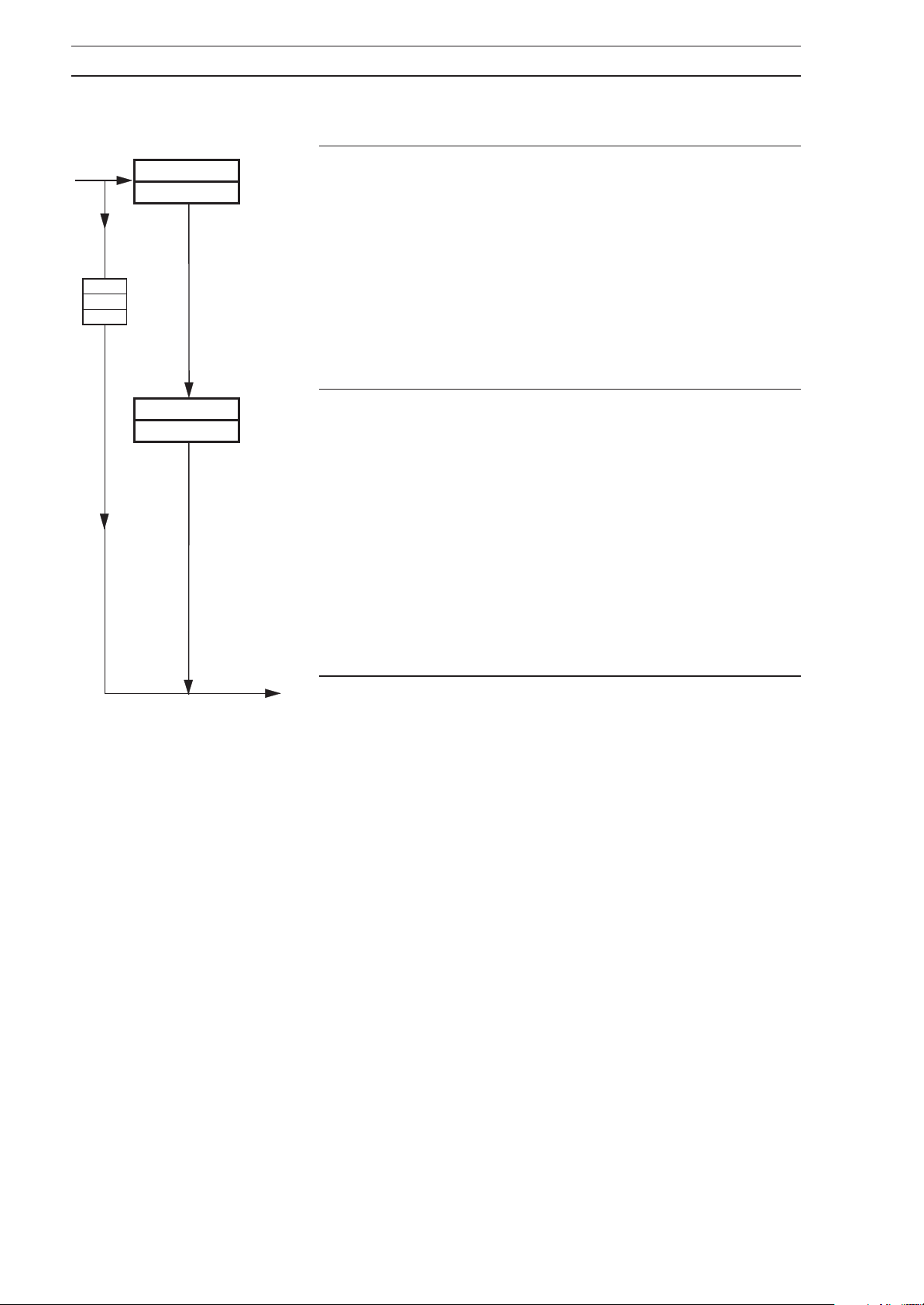
Heat Output High Limit
This limits the high level of the Heat control output value
when in Automatic mode. If the control output is above this
limit when Automatic mode is selected, the output is
allowed to stay at its current level but is not allowed to go
any higher. Once the control output returns to, or falls
below, this limit, the limit then applies. When the controller
is in Manual mode, the output limits do not apply. Select
the heat output high limit value required, between 0.0 and
100.0% in 0.1 increments.
Cool Output High/Low Limit
This limits the high or low level of the Cool control output
when in Automatic mode, depending on the
frame setting (rEV is the low and dIr is the high
(Cool)
setting). If the control output exceeds this limit when
Automatic mode is selected, the output remains at its
current level but is not allowed to go any further away from
the limit. Once the control output returns to, or again falls
within this limit, the limit then applies. When the controller
is in Manual mode, the output limits do not apply. Select
the Cool output high (low) limit required, between 0.0 and
100.0% in 0.1 increments.
Control Action
Continued on next page.
34
Page 37
…4.10 Set Up Control Page
Option
board
error
OPtION
ON
4 CONFIGURATION…
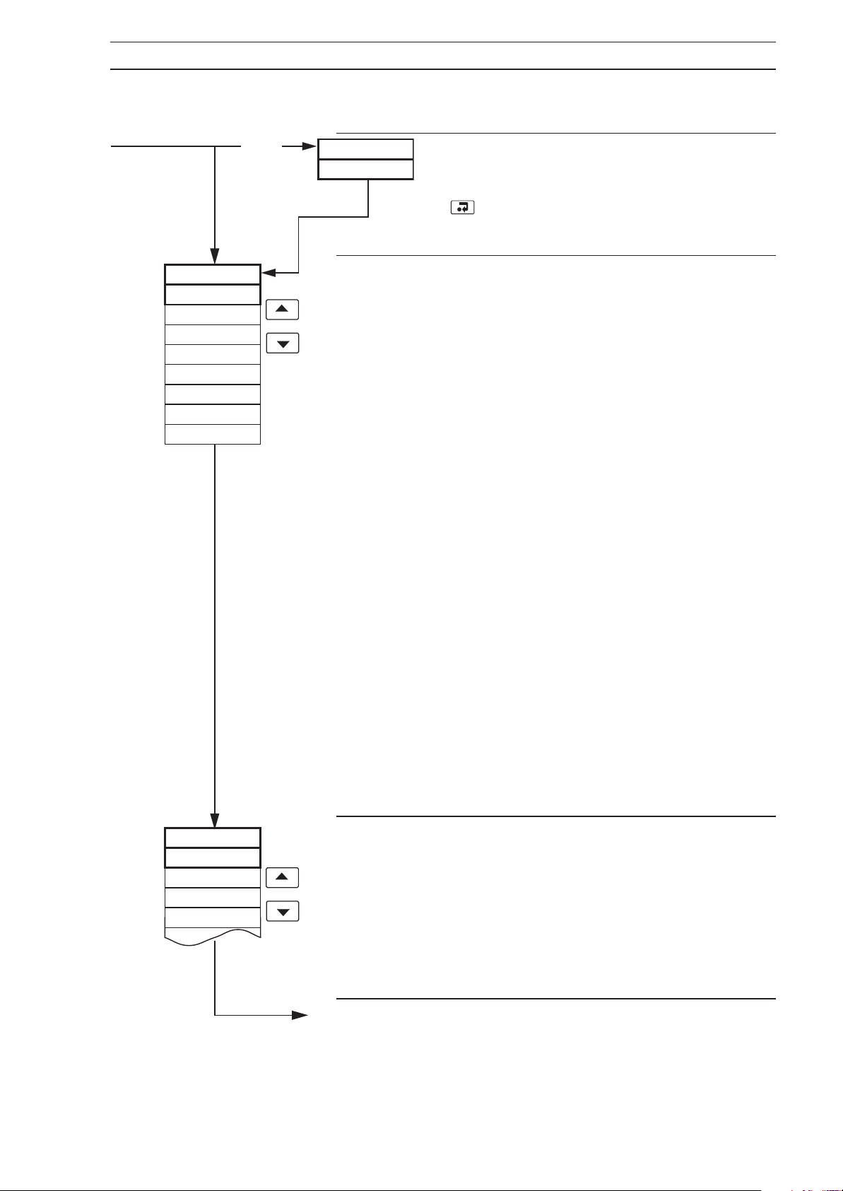
Option Board Disable (not applicable to wall-
/pipe-mounted variants)
If the Option board fails or is removed, press
to set OPtION to OFF. Once set to OFF,
this parameter is omitted.
LOGIC1
NONE
AUt MAN
LOCrE M
ACK
F-SPt
P-Strt
P-rSEt
P-SKIP
Logic Input Type 1
Refer to
Guide
Select the logic input type for input 1 (must not be the same
as any other logic input type):
Section 4, Figs 4.18 and 4.19 in the Installation
.
NONE – no function available
AUtMAN – auto/manual
LOCrE M – local/remote (dual)
ACK – remote alarm acknowledge
F-SPt – fixed dual set point
P-Strt – program start/hold function
P-rSEt – program reset function
P-SKIP – segment skip function
If
AUtMAN is selected, the output reverts to the value set in
Configured Output below, unless configured output is set to
LASt.
F–SPt is selected, two fixed set points are available –
If
see
Fixed Dual Set Point 1 and Fixed Dual Set Point 2 below.
F–SPt is selected, the adjustable dual set point facility
If
is disabled and the dual set point is the value of one of the
two fixed set points.
Dual set point must be selected (in
Section 4.2) in order to enable the use of the fixed set
points.
dUAL is selected at Set Point Type Selection frame in Set
If
Points Page,
Dual selection.
the Local/Remote selection becomes Local/
Set Points Page –
LOGIC2
NONE
AUt MAN
LOCrE M
ACK
Logic Input Type 2
Refer to
Guide
Select the logic input type for input 2 (must not be the same
as any other logic input type). The selections and their
actions are as for Logic Input 1 above – refer to Logic Input
frame for details.
1
Continued on next page.
Section 4, Figs. 4.18 and 4.19 in the Installation
.
35
Page 38
…4 CONFIGURATION
…4.10 Set Up Control Page
LOGIC3
NONE
LOGIC4
NONE
C–OUt
LASt
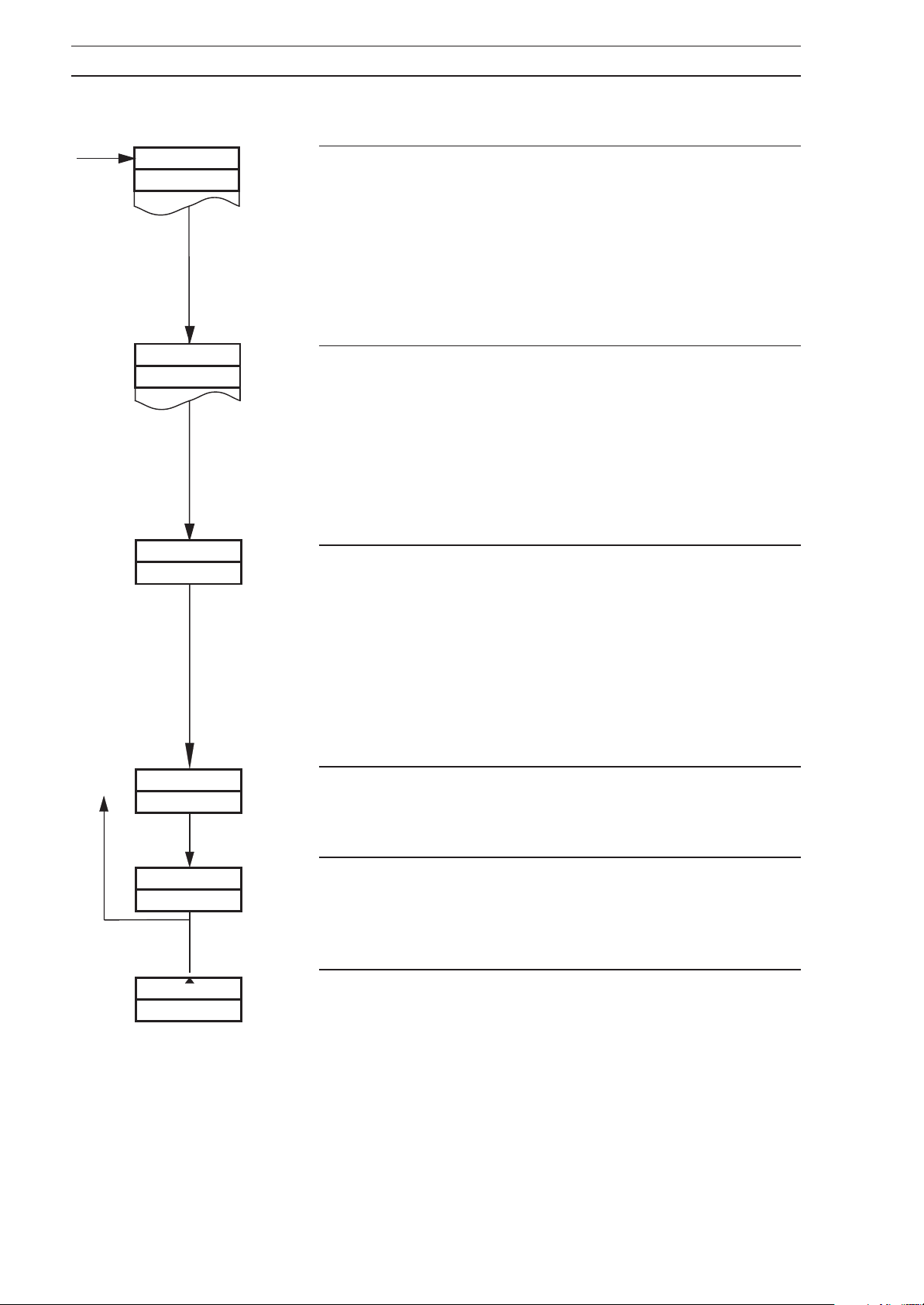
Logic Input Type 3 (not available on wall-/pipe-mounted
variants)
Refer to
Guide
Select the logic input type for input 3 (must not be the same
as any other logic input type). The selections and their
actions are as for Logic Input 1 – refer to Logic Input 1
frame for details.
Logic Input Type 4 (not available on wall-/pipe-mounted
variants)
Refer to
Guide
Select the logic input type for input 4 (must not be the same
as any other logic input type). The selections and their
actions are as for Logic Input 1 – refer to Logic Input 1
frame for details.
Configured Output
Select the configured output, between 0.0 and 100.0% in
0.1% increments, or LASt.
If
AUtMAN is selected for any of the logic inputs above, the
manual control output equals the
unless the configured output is
Section 4, Figs. 4.18 and 4.19 in the Installation
.
Section 4, Figs. 4.18 and 4.19 in the Installation
.
Configured Output,
LASt.
LASt – last auto output, i.e. the manual output
tracks the automatic output. Found
below 0%.
F–SP–I
800
F–SP–2
200
SEtUP
ALArMS
Fixed Dual Set Point 1
If the selection in any of the four logic inputs is
fixed set point may be set. Set the fixed set point required.
Fixed Dual Set Point 2
If the selection in any of the four logic inputs is
fixed set point may be set. Set the fixed set point value
required.
Return to the top of Set Up Control Page or advance to the
next programming page.
F–SPt, a
F–SPt, a
36
Page 39
4 CONFIGURATION
4.11 Set Up Alarms Page
Information.
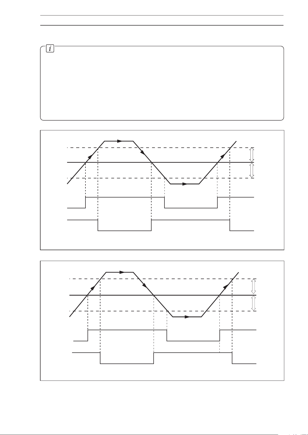
• Ten alarms – identified A to K.
• Three operator acknowledge options.
• Global alarm acknowledgment by digital input, alarm, logic equation result or real-time
event (if option fitted).
• High/low process alarms.
• High/low output alarms.
• High/low deviation alarms.
• Fast/slow rate-of-change-of-process-variable alarms.
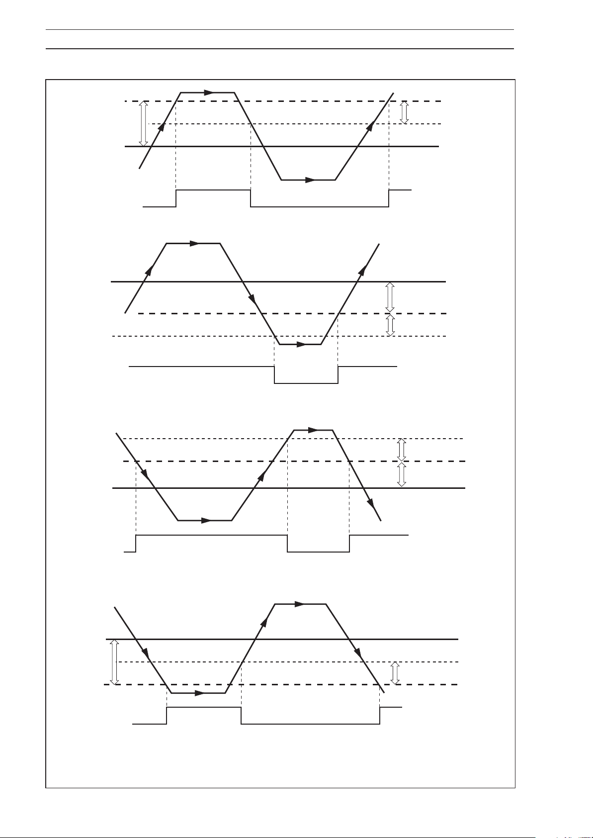
• Adjustable hysteresis value to prevent oscillation of alarm state.
Hysteresis
Trip Point
Process V ariable
High
Process
Low
Process
Control
Output
Hysteresis
Alarm On
Alarm Off
Alarm On
Alarm Off
Fig. 4.9 High and Low Process with Hysteresis
Hysteresis
Trip Point
Hysteresis
Alarm On
High Output
Low Output
Alarm Off
Alarm On
Alarm Off
Fig. 4.10 High and Low Output with Hysteresis
37
Page 40
…4 CONFIGURATION
…4.11 Set Up Alarms Page
High Deviation
Positive Trip
Value
Process
Variable
High Deviation
(Positive Trip)
Control
Set Point
Process
Variable
High Deviation
(Negative Trip)
Hysteresis V alue
Control
Set Point
Alarm On
Alarm Off
A – High Deviation (Positive Trip) with Hysteresis
High Deviation
Negative Trip Value
Hysteresis V alue
Alarm On
Alarm Off
Process
Variable
Control
Set Point
Low Deviation
(Positive Trip)
Process
Variable
Low
Deviation
Negative
T rip V alue
B – High Deviation (Negative Trip) with Hysteresis
Hysteresis V alue
Low Deviation
Positive Trip Value
Alarm On
Alarm Off
C – Low Deviation (Positive Trip) with Hysteresis
Control
Set Point
Hysteresis V alue
Low Deviation
(Negative Trip)
38
Alarm On
Alarm Off
D – Low Deviation (Negative Trip) with Hysteresis
Fig. 4.11 High and Low Deviation with Hysteresis
Page 41
…4.11 Set Up Alarms Page
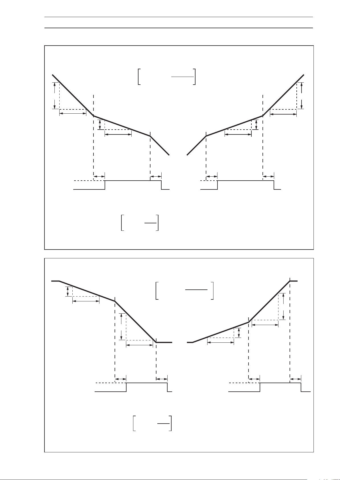
The maximum time it takes to detect whether
an alarm condition is present (T), in seconds,
is calculated as follows:
T = 10.81 + x 2
4 CONFIGURATION…
1800
Trip V alue
10.1
1 hour
9.5
Alarm On
Alarm Off
Examples shown are for a trip value of 10%/hour on a PV engineering range of 0.0 to 100.0
The time it takes for the alarm state to be
cleared once the alarm condition has been
removed is also equal to T.
1 hour
Alarm On
Alarm Off
Falling Slow Rate Rising Slow Rate
T = 10.81 + x 2
Fig. 4.12 Slow Rate Alarms with Hysteresis
1800
10
T = 382 seconds
1 hour
T T T
9.5
10.1
1 hour
T
The maximum time it takes to detect whether
an alarm condition is present (T), in seconds,
is calculated as follows:
T = 10.81 + x 2
9.5
1 hour
10.1
Alarm On
Alarm Off
Falling Fast Rate
Examples shown are for a trip value of 10%/hour on a PV engineering range of 0.0 to 100.0
The time it takes for the alarm state to be
cleared once the alarm condition has been
removed is also equal to T.
1 hour
T T
T = 10.81 + x 2
1800
10
1800
Trip V alue
10.1
1 hour
9.5
1 hour
Alarm On
Alarm Off
Rising Fast Rate
T = 382 seconds
T T
Fig. 4.13 Fast Rate Alarms with Hysteresis
39
Page 42
…4 CONFIGURATION
…4.11 Set Up Alarms Page
SEtUP
ALArMS
ALArM
tYPE
––––
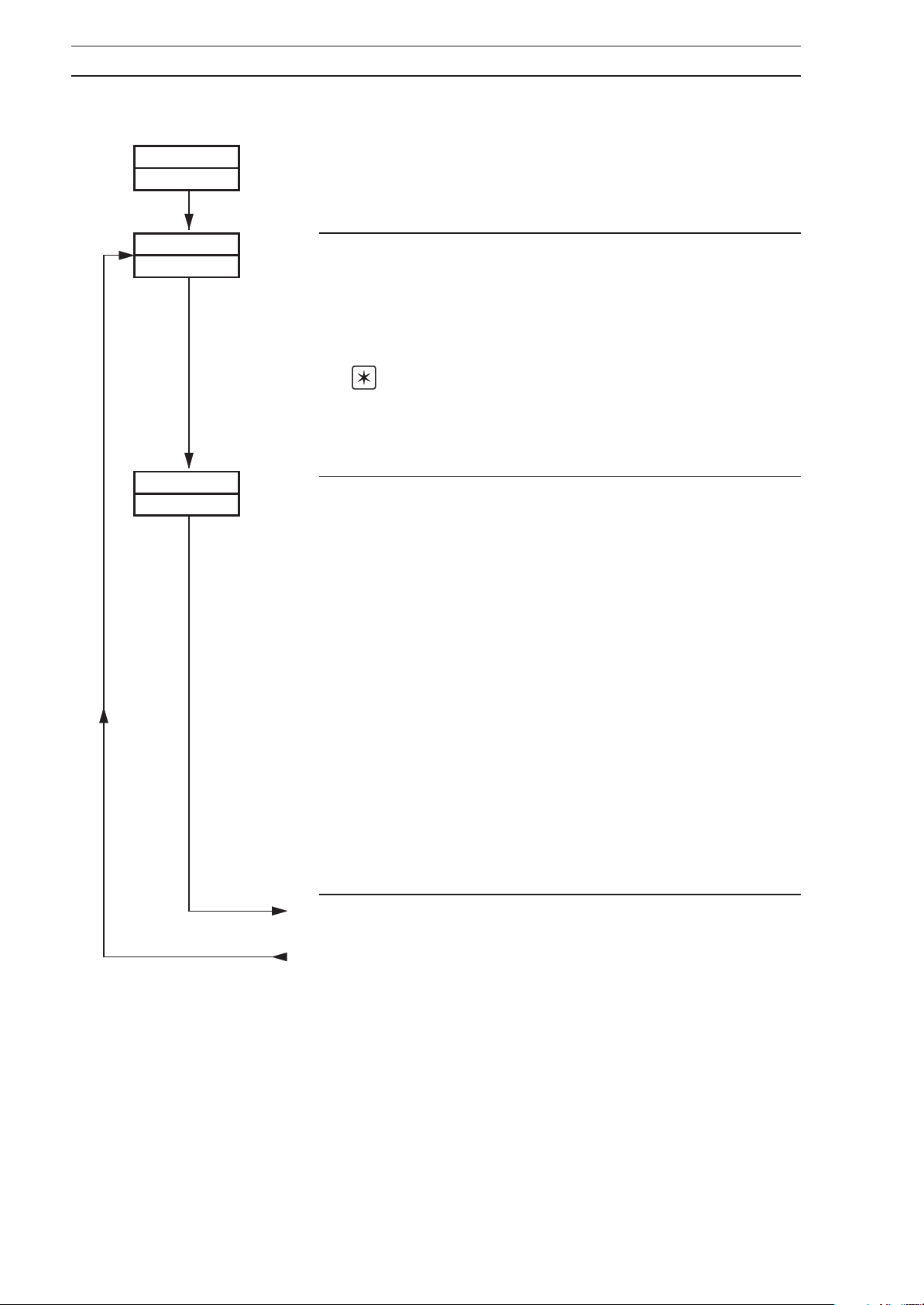
Page Header – Set Up Alarms.
Alarm Identities
–
Up to ten alarms (A to K but not I) can be programmed.
Each alarm can be assigned an Alarm Type, a Trip Level
and a Hysteresis setting. Alarm A is the highest priority
and K the lowest.
Note. The alarm status LED indicators are:
A1 – alarms A to E
A2 – alarms F to K.
Select the Alarm identity.
Alarm Type
An alarm type can be assigned to the alarm identity
selected above – Refer to Figs. 4.9 to 4.13.
Select the alarm type:
NONE – no alarm function
HPrC – high process
LPrC – low process
HdEV – high deviation
LdEV – low deviation
HOUt – high output
LOUt – low output
FrtE – fast rate
(rate of change of process variable)
SrtE – slow rate
(rate of change of process variable)
MOdE – mode alarm
PEVt – program event
SEVt – segment event
40
(a) Continued on next page.
From page 41
(b) From More Alarms to be Programmed frame.
Page 43
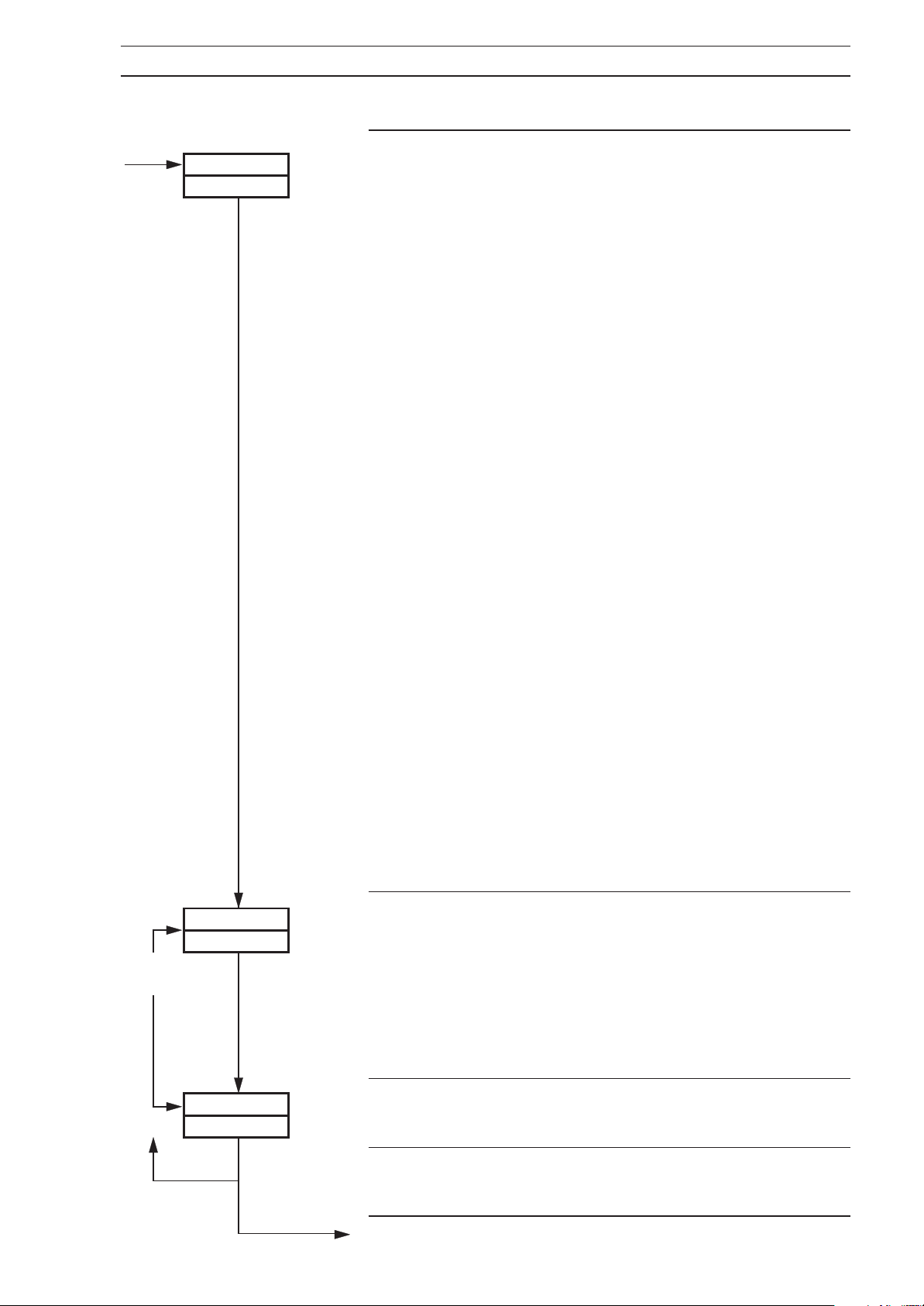
…4.11 Set Up Alarms Page
trIP
––––
4 CONFIGURATION…
Trip Level
Set the trip value required for the alarm selected above.
The following are displayed in engineering units:
HPrC, LPrC, HdEV and LdEU.
HdEV and LdEV alarms have both positive and negative
trip points. Refer to Fig. 4.11.
The following are displayed as percentages:
HOUt and LOUt.
The following are displayed as a percentage of span per
hour between ±0.5 and ±500%:
FrtE and SrtE.
The following are displayed as event numbers:
PEVt (1 to 9) and SEVt (1 to 30).
If the
are alpha, not numeric. The following codes are
selectable:
Alarm Type is set to MOdE, the displayed characters
AUtO – Automatic
MANUAL – Manual
L–SPt – Local set point
r–SPt – Remote set point – only selectable if
Second set point type is Remote set
point
dSPt – Dual set point – only selectable if
Second set point type is Dual set point
PVFAIL – process variable failure
rSFAIL – Remote set point failure
PNFAIL – position feedback failure
INFAIL – any input failure
P–HOLd – alarm activated when program is on
Hold (Profile only)
AUtO, MANUAL, L–SPt, r–SPt, or d–SPt is selected
If
and an attempt is made to use that facility (Automatic,
Manual, Local set point, Remote set point, or Dual set
point), the alarm is activated.
More
alarms
YES
HYSt
– – – –
MOrE
–––
no
Hysteresis
The hysteresis is operational when the alarm is active.
Set the hysteresis value required (in engineering units),
between display full scale and zero, or percentage rate set
on rate alarms, in 0.1% increments. The alarm is activated
at the trip level, but is only turned off after the alarm
variable has moved into the safe region by an amount
equal to the hysteresis value. Refer to Figs. 4.9 to 4.13.
More Alarms to be Programmed?
If there are, select
Return to Alarm Identities frame, or advance to the next
parameter.
Continued on next page
YES otherwise, select no.
41
Page 44
…4 CONFIGURATION
…4.11 Set Up Alarms Page
r–FLtr
– –
rELAYI
– – – – – –
t–PrOP
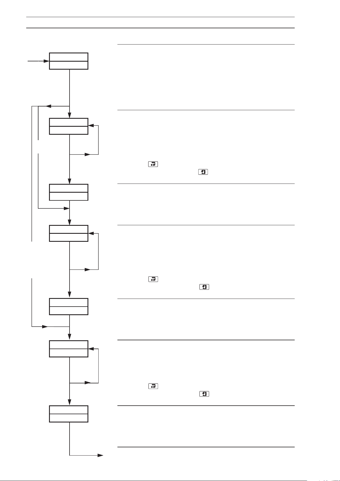
Rate Alarm Filter
The process variable input can be filtered before its rate of
change is calculated to activate any fast or slow rate
alarms. The filter time represents the time a step in the
input takes to change the input to the rate alarm from 10 to
90% of the step. Set value required, between 0 and 60 in
1 second increments.
Alarm Relay 1 Assignment
Up to 6 of the 10 alarms can be assigned to alarm relay 1,
using a logic expression of up to 12 characters. (r = logic
OR,
n = logic AND, () are brackets and W is the
terminator.)
Select the next character in the expression.
Press
next character or press
to store the character and return to select the
to advance to the next frame.
P–PrOP
bndLSS,
or
second
output
t–PrOP
rI–ACt
POS
rELAY2
– – – – – –
r2–ACt
POS
rELAY3
– – – – – –
Relay 1 Action
Select
expression is satisfied. Select
energized when the logic expression is satisfied.
Alarm Relay 2 Assignment
Up to 6 of the 10 alarms can be assigned to alarm relay 2,
using a logic expression of up to 12 characters. (r = logic
OR,
terminator.)
Select the next character in the expression.
Press
next character, or press
Relay 2 Action
Select
expression is satisfied. Select
energized when the logic expression is satisfied.
Alarm Relay 3 Assignment
Up to 6 of the 10 alarms can be assigned to alarm relay 3,
using a logic expression of up to 12 characters. (r = logic
OR,
terminator.) Select the next character in the expression.
Press to store the character and return to select the
next character, or press
POS for the relay to be energized when the logic
NEG for the relay to be de-
n = logic AND, () are brackets and W is the
to store the character and return to select the
to advance to the next frame.
POS for the relay to be energized when the logic
NEG for the relay to be de-
n = logic AND, () are brackets and W is the
to advance to the next frame.
42
r3–ACt
POS
Relay 3 Action
Select
expression is satisfied. Select
energized when the logic expression is satisfied.
Continued on next page.
POS for the relay to be energized when the logic
NEG for the relay to be de-
Page 45
…4.11 Set Up Alarms Page
4 CONFIGURATION…
rELAY4
– – – – – –
r4–ACt
POS
AL–MSGE
YES
ACKNLG
NONE
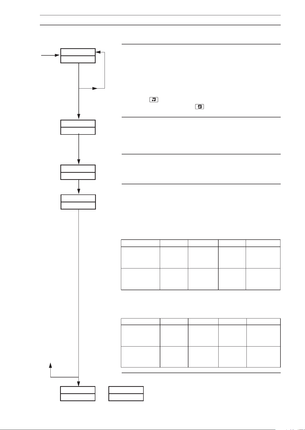
Alarm Relay 4 Assignment (not available on wall-/pipemounted variants)
Up to 6 of the 10 alarms can be assigned to alarm relay 4,
using a logic expression of up to 12 characters. (
OR,
n = logic AND, () are brackets and W is the
terminator.)
Select the next character in the expression.
Press
next character, or press
Relay 4 Action (not available on wall-/pipe-mounted variants)
Select
expression is satisfied. Select
energized when the logic expression is satisfied.
Alarm Message Enable
Set
YES to enable, or no to disable the display of alarm
messages in the
Alarm Acknowledge Type
Alarms may be acknowledged while they are displayed.
Select the alarm acknowledge type:
to store the character and return to select the
to advance to the next frame.
POS for the relay to be energized when the logic
NEG for the relay to be de-
Operating Page.
r = logic
NONE – no acknowledge facility.
norMAL – If the cause of the alarm no longer exists,
the alarm state clears, but the display
remains until alarm is acknowledged.
Alarm cause Acknow. Display LED Alarm State
Present – Flashing Flashing Active
Present Yes – Steady Active
Not present – – Off Inactive
Present
Not present – Flashing Off Inactive
Not present Yes – Off Inactive
–
Flashing Flashing Active
OUtPUt
or
LAtCH
Alarm cause Acknow. Display LED Alarm State
Present – Flashing Flashing Active
Present Yes – Steady Active
Not present – – Off Inactive
Present – Flashing Flashing Active
Not present – Flashing Flashing Active
Not present Yes – Off Inactive
Return to top of Set Up Alarms Page or advance to
next programming page.
– if the cause of the alarm no longer exists,
the alarm state remains until it has been
acknowledged.
COOLrEtrAN
OUtPUt
43
Page 46
…4 CONFIGURATION
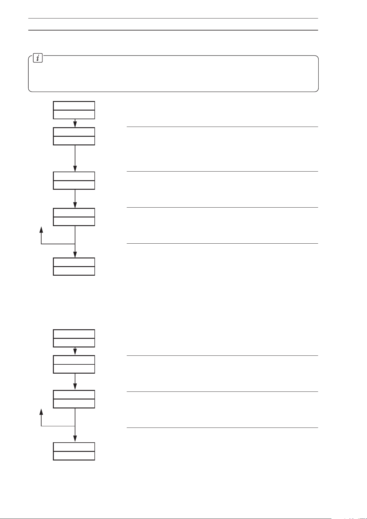
4.12 Retransmission Output Page
Information.
• Retransmission of process variable, set point, control output or position feedback input.
• Programmable current output range.
• Retransmission output can be used for cool output in heat/cool applications.
rEtrAN
OUtPUt
tYPE
PU.
rEt–HI
20.0
rEt–LO
4.0
SCALE
AdJUSt
Page Header – Retransmisson Output.
Parameter Type
Select the parameter type to be retransmitted,
variable input),
(position feedback).
Retransmission Maximum
Set the maximum retransmission value, between 0.0mA
and 20.0mA in 0.1mA increments.
Retransmission Minimum
Set the minimum retransmission value, between 0.0mA
and 20.0mA in 0.1mA increments.
Return to top of Retransmission Output Page
or
Advance to
SPt (set point), OUt (output) or PFb
Scale Adjustment Page.
PV (process
4.13 Cool Output Page
This page is only present if HtCOOL is selected at Control Mode and C-ProP is selected at
Second Output Type in the Set Up Control Page – see Fig. 3.1 and Section 4.10.
COOL
Page Header – Cool Output Page
OUtPUt
COOL–HI
20.
0
COOL–LO
4.0
SCALE
AdJUSt
Cool Output Maximum
Set the maximum value for the cool output, between
0.0mA and 20.0mA in 0.1mA increments.
Cool Output Minimum
Set the minimum value for the cool output, between 0.0mA
and 20.0mA in 0.1mA increments.
Return to top of Cool Output Page
or
advance to
Scale Adjustment Page.
44
Page 47
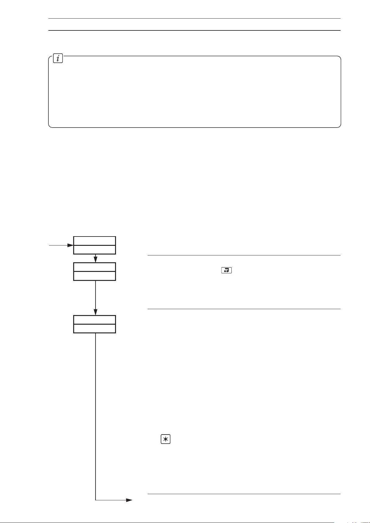
4 CONFIGURATION…
4.14 Scale Adjustment Page
Information.
• Process variable, Remote set point and position feedback inputs do not require
recalibrating when the input type or range is changed.
• Scale Adjustment Reset – removes any previously programmed offset or scale
adjustment settings.
• System offset errors – can be removed using Offset Adjustment.
• System scale errors – can be removed using Span Adjustment.
• Offset/Span Adjustment – can be used to perform spot calibration.
Switch off the power supply. Connect accurate signal sources, suitable for simulation over the
entire input ranges, in place of the process variable signal connections (terminals 10, 11, 12),
remote set point signal connections (terminals 7, 8 and 9) and position feedback connections
(terminals 4, 5 and 6). For thermocouple inputs, connect the millivolt source using appropriate
compensating cable – see
thermometers, the resistance box may be connected at the sensor end of the leads or the lead
resistance must be added to the calibration values.
As a general rule, spot calibration values should be:
< 50% of range span value when using Offset Adjustment parameters.
> 50% of range span value when using Span Adjustment parameters.
Section 4.6.1 of the Installation Guide
. For 2-lead resistance
SCALE
AdJUSt
PV–rSt
no
PV–OFS
––––
Page header – Scale Adjustment
Process Variable Scale Adjustment Reset
Set
YES and press to reset the process variable offset
and span values to their nominal values.
displayed to indicate that these parameters have been
reset.
Process Variable Offset Adjustment
Electrical and resistance thermometer inputs:
Apply the correct input for the spot calibration required.
For RTD inputs, use resistance values obtained from
standard tables.
Thermocouple Inputs:
Measure the ambient temperature at the output terminals
of the signal source (calibrator). From thermocouple
tables, obtain the millivolt equivalent of this temperature
(a) and that for the spot calibration temperature (b).
Subtract (a) from (b) and set the signal source to the
resultant value. (The voltage is negative if the spot
calibration temperature is less than the measured ambient
temperature.)
dONE is
Note. The displayed units are engineering units.
Set the value required. The decimal point position is set
automatically.
Example – If the display range is 50 to 250.0 and a spot
calibration is required at 100.0 and 225, inject a signal
equivalent to 100 and set the display to 100.0.
Continued on next page.
45
Page 48
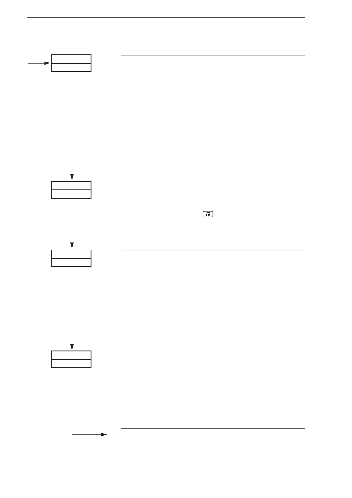
…4 CONFIGURATION
4.14 Scale Adjustment Page
PV–SPN
––––
rS–rSt
no
Process Variable Span Adjustment
Proceed as for
apply the correct input for the spot calibration required.
The displayed units are engineering units.
Set the value required. The decimal point position is set
automatically.
For the example above inject a signal equivalent to 225.0
and set the display to 225.0.
Advance to Position Feedback Scale Adjustment Reset
frame (instruments on which remote set point is not
selected – see
or advance to next frame (instruments with remote set
point selected).
Remote Set Point Scale Adjustment Reset
The next three parameters are only included if the Remote
set point facility is selected.
Set to
offset and span adjustments to their nominal values.
is displayed to indicate that these parameters have been
reset.
YES and press to reset the Remote set point
Process Variable Offset Adjustment and
Set Point Selection frame in Set Points Page)
dONE
rS–OFS
––––
rS–SPN
––––
Remote Set Point Offset Adjustment
Proceed as for
and apply the correct input for the spot calibration required.
The displayed units are engineering units as set in Set Up
Remote Set Point Page
Set the value required. The decimal point position is set
automatically.
Example – If the remote set point range (see Section 4.6)
is 50.0 to 250.0 and a spot calibration is required at 100.0
and 225, inject a signal equivalent to 100 and set the
display to 100.0.
Remote Set Point Span Adjustment
Proceed as for
and apply the correct input for the spot calibration required.
Ratio and bias settings are ignored. The displayed units
are engineering units as set in
– see Section 4.6.
For the example above, inject a signal equivalent to 225
and set the display to 225.0.
Process Variable Offset Adjustment frame
– see Section 4.6.
Process Variable Span Adjustment frame
Set Up Remote Set Point Page
46
Continued on next page.
Page 49
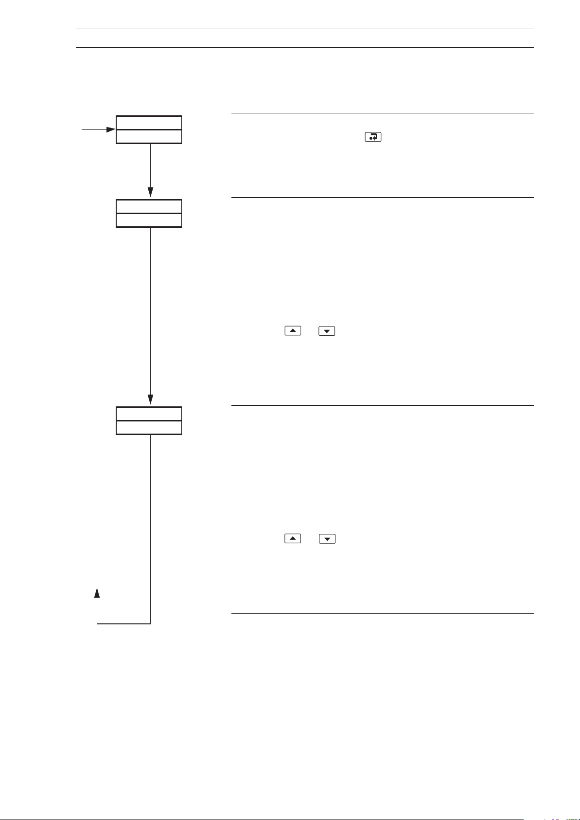
4 CONFIGURATION…
4.14 Scale Adjustment Page
The next three parameters are only included if the position feedback facility is selected.
Fb–rSt
Fb–OFS
––––
no
Position Feedback Scale Adjustment Reset
Set to
offset and span adjustments to their nominal values.
is displayed to indicate that these parameters have been
reset.
Position Feedback Offset Adjustment
Proceed as for
and apply the correct input for the spot calibration required.
Ratio and bias settings are ignored.
Set the value required. The decimal point position is set
automatically. For resistance inputs, use the external
connections to drive the valve to the fully closed position.
Adjust or to bring the value displayed to that set in
the Position Feedback Range Zero frame in the Set Up
Position Feedback Page
adjust the value in
bring it within the offset bandwidth of ±10%.
YES and press to reset the position feedback
dONE
Process Variable Offset Adjustment frame
. If this value cannot be reached,
Position Feedback Range Zero frame to
Fb–SPN
––––
Position Feedback Span Adjustment
Proceed as for
and apply the correct input for the spot calibration required.
Ratio and bias settings are ignored.
Set the value required. The decimal point position is set
automatically. For resistance inputs, use the external
connections to drive the valve to the fully open position.
Adjust or to bring the value displayed to that set in
the
Position Feedback Range Full Scale frame in the Set Up
Position Feedback Page
adjust the value in
frame to bring it within the span bandwidth of ±10%.
Return to the top of the Scale Adjustment Page.
Process Variable Span Adjustment frame
. If this value cannot be reached,
Position Feedback Range Full Scale
47
Page 50
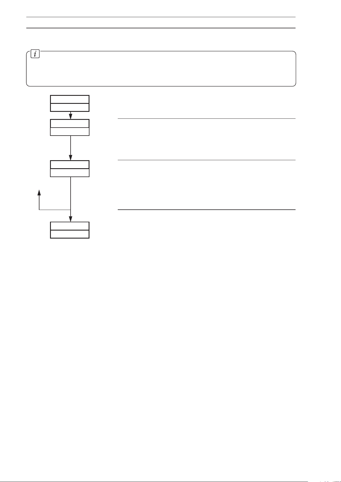
…4 CONFIGURATION
4.15 Access Page
Information.
Tune Password – protects the control settings and prevents unauthorized use of self-
•
tuning.
Configuration Password – protects the controller configuration set up.
•
ACCESS
PAGE
C–PASS
t–PASS
– –––
– –––
Page Header – Access Page.
Configuration Password
0
0
The configuration password enables access to all
programming pages (Security Level 2).
Set the required password, between 0 and 1999.
Tuning Password
The tuning password enables access to the
Control, Profile States
addition to the
Set the required password, between 0 and 1999.
Return to top of Access Page
or
return to
Guide
.
Operating Page (Security Level 1).
Operating Page – see
and Profile Operating Pages in
Section 5.2 of Operating
Self-tune,
48
Page 51

WARRANTY/DISCLAIMER
OMEGA ENGINEERING, INC. warrants this unit to be free of defects in materials and workmanship for a
period of 37 months from date of purchase. OMEGA Warranty adds an additional one (1) month
grace period to the normal three (3) year product warranty to cover handling and shipping time.
This ensures that OMEGA’s customers receive maximum coverage on each product.
If the unit malfunctions, it must be returned to the factory for evaluation. OMEGA’s
Customer Service Department will issue an Authorized Return (AR) number immediately upon phone
or written request. Upon examination by OMEGA, if the unit is found to be defective, it will be repaired
or replaced at no charge. OMEGA’s WARRANTY does not apply to defects resulting from any action of
the purchaser, including but not limited to mishandling, improper interfacing, operation outside of
design limits, improper repair, or unauthorized modification. This WARRANTY is VOID if the unit shows
evidence of having been tampered with or shows evidence of having been damaged as a result of
excessive corrosion; or current, heat, moisture or vibration; improper specification; misapplication;
misuse or other operating conditions outside of OMEGA’s control. Components which wear are not
warranted, including but not limited tocontact points, fuses, and triacs.
OMEGA is pleased to offer suggestions on the use of its various products. However,
OMEGA neither assumes responsibility for any omissions or errors nor assumes
liability for any damages that result from the use of its products in accordance with information
provided by OMEGA, either verbal or written. OMEGA warrants only that the parts
manufactured by it will be as specified and free of defects. OMEGA MAKES NO OTHER
WARRANTIES OR REPRESENTATIONS OF ANY KIND WHATSOEVER, EXPRESS OR IMPLIED,
EXCEPT THAT OF TITLE, AND ALL IMPLIED WARRANTIES INCLUDING ANY WARRANTY OF
MERCHANTABILITY AND FITNESS FOR A PARTICULAR PURPOSE ARE HEREBY DISCLAIMED.
LIMITATION OF LIABILITY: The remedies of purchaser set forth herein are exclusive, and the
total liability of OMEGA with respect to this order, whether based on contract, warranty,
negligence, indemnification, strict liability or otherwise, shall not exceed the purchase price of
the component upon which liability is based. In no event shall OMEGA be liable for
consequential, incidental or special damages.
CONDITIONS: Equipment sold by OMEGA is not intended to be used, nor shall it be used: (1) as a
“Basic Component” under 10 CFR 21 (NRC), used in or with any nuclear installation or activity; or (2) in
medical applications or used on humans. Should any Product(s) be used in or with any nuclear
installation or activity, medical application, used on humans, or misused in any way, OMEGA assumes
no responsibility as set forth in our basic WARRANTY / DISCLAIMER language, and, additionally,
purchaser will indemnify OMEGA and hold OMEGA harmless from any liability or damage whatsoever
arising out of the use of the Product(s) in such a manner.
RETURN REQUESTS / INQUIRIES
Direct all warranty and repair requests/inquiries to the OMEGA Customer Service Department.
BEFORE RETURNING ANY PRODUCT(S) TO OMEGA, PURCHASER MUST OBTAIN AN AUTHORIZED
RETURN (AR) NUMBER FROM OMEGA’S CUSTOMER SERVICE DEPARTMENT (IN ORDER TO AVOID
PROCESSING DELAYS). The assigned AR number should then be marked on the outside of the
return package and on any correspondence.
The purchaser is responsible for shipping charges, freight, insurance and proper packaging to
prevent breakage in transit.
FOR WARRANTY
following information available BEFORE
contacting OMEGA:
1. Purchase Order number under which
the product was PURCHASED,
2. Model and serial number of the product under
warranty, and
3. Repair instructions and/or specific
problems relative to the product.
RETURNS, please have the
FOR NON-WARRANTY REPAIRS,
OMEGA for current repair charges. Have the
following information available BEFORE
contacting OMEGA:
1. Purchase Order number to cover the COST of
the repair,
2. Model and serial number of the product, and
3. Repair instructions and/or specific problems
relative to the product.
consult
OMEGA’s policy is to make running changes, not model changes, whenever an improvement is possible.
This affords our customers the latest in technology and engineering.
OMEGA is a registered trademark of OMEGA ENGINEERING, INC.
© Copyright 1998 OMEGA ENGINEERING, INC. All rights reserved. This document may not be copied,
photocopied, reproduced, translated, or reduced to any electronic medium or machine-readable form, in
whole or in part, without the prior written consent of OMEGA ENGINEERING, INC.
Page 52

Where Do I Find Everything I Need for
Process Measurement and Control?
OMEGA…Of Course!
TEMPERATURE
Thermocouple, RTD & Thermistor Probes, Connectors, Panels & Assemblies
Wire: Thermocouple, RTD & Thermistor
Calibrators & Ice Point References
Recorders, Controllers & Process Monitors
Infrared Pyrometers
PRESSURE, STRAIN AND FORCE
Transducers & Strain Gauges
Load Cells & Pressure Gauges
Displacement Transducers
Instrumentation & Accessories
FLOW/LEVEL
Rotameters, Gas Mass Flowmeters & Flow Computers
Air Velocity Indicators
Turbine/Paddlewheel Systems
Totalizers & Batch Controllers
pH/CONDUCTIVITY
pH Electrodes, Testers & Accessories
Benchtop/Laboratory Meters
Controllers, Calibrators, Simulators & Pumps
Industrial pH & Conductivity Equipment
DATA ACQUISITION
Data Acquisition & Engineering Software
Communications-Based Acquisition Systems
Plug-in Cards for Apple, IBM & Compatibles
Datalogging Systems
Recorders, Printers & Plotters
HEATERS
Heating Cable
Cartridge & Strip Heaters
Immersion & Band Heaters
Flexible Heaters
Laboratory Heaters
ENVIRONMENTAL
MONITORING AND CONTROL
Metering & Control Instrumentation
Refractometers
Pumps & Tubing
Air, Soil & Water Monitors
Industrial Water & Wastewater Treatment
pH, Conductivity & Dissolved Oxygen Instruments
M2952/0299
 Loading...