

Page 1
1
t
)
r
/
- 1/8 - 1/4 DIN LIMIT CONTROLLERS
16
CN2516, CN2508, CN2504
CAUTION: Installation should be only performed by
technically competent personnel. Local Regulations
regarding electrical installation & safety must be observed.
1. INSTALLATION
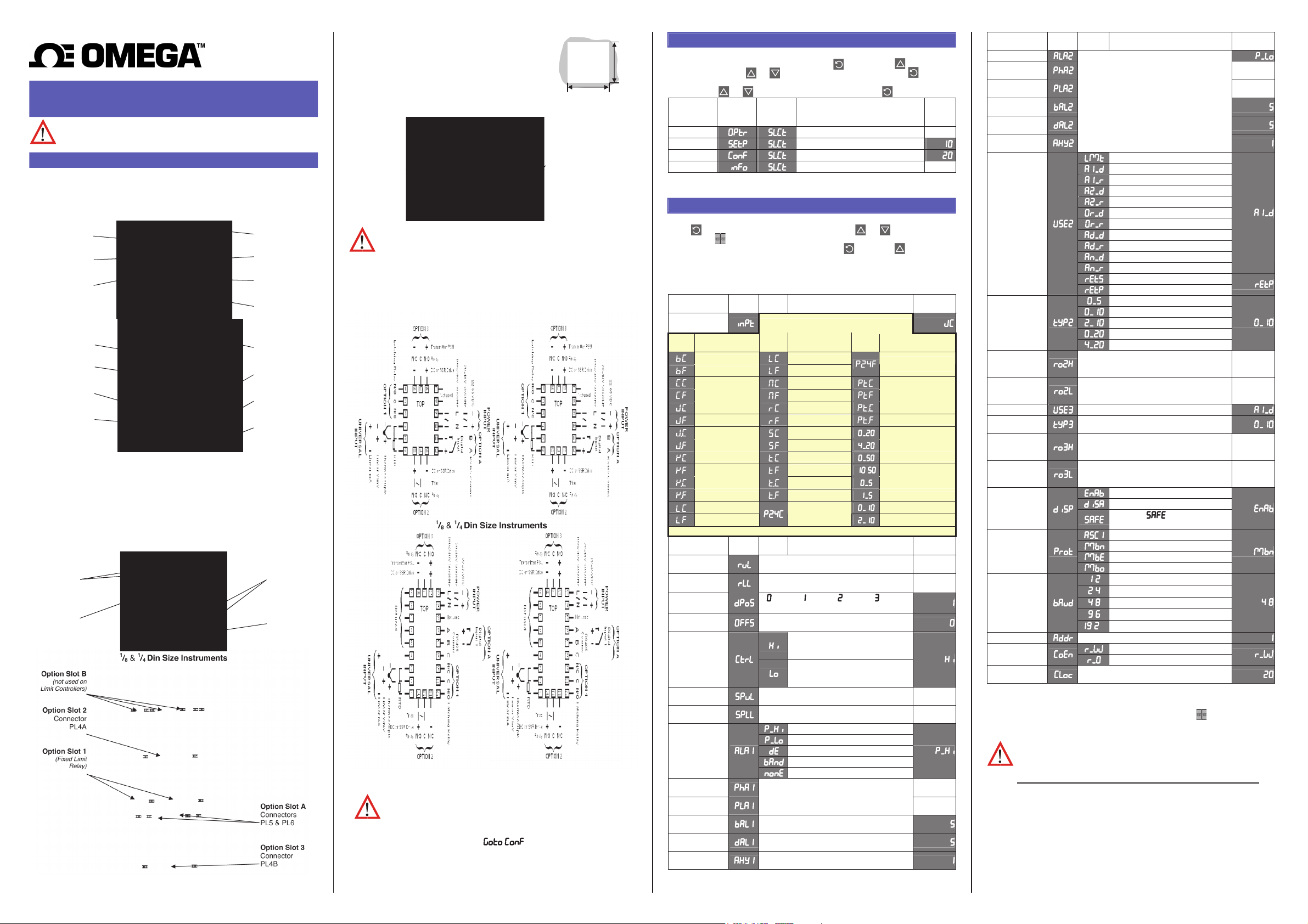
The models covered by this manual have three different DIN case sizes (refer to
section 9). Some installation details vary between models. These differences have
been clearly shown.
Note: The functions described in sections 2 thru 8 are common to all models.
Installing Option Modules
1
/
Din Size Instrume
16
CPU PCB
Option Module 1
(Fixed Limit Relay)
Option Module 2
1
/8 & 1/4 Din Size
Instruments
CPU PCB
Option Module B
(not used on Limit
Controllers)
Option Module 2
Option Module 1
(Fixed Limit Relay)
To access module A, first detach the PSU and CPU boards from the front by lifting
first the
upper, and then lower mounting struts. Gently separate the boards.
a. Plug the required option modules into the correct connectors, as shown below.
b. Locate the module tongues in the corresponding slot on the opposite board.
c. Hold the main boards together while relocating back on the mounting struts.
d. Replace the instrument by aligning the CPU and PSU boards with their guides
in the housing, then slowly push the instrume
Note: Option modules are automatically detected at power up.
Option Module Connectors
Option Slot 1
(Fixed Limi
Relay
Option Slot 2
Connecto
PL4A
nts
1
/
Din Size Instruments
16
Mounting Struts
Option Module A
Option Module 3
PSU PCB
Mounting Struts
Option Module A
Option Module 3
PSU PCB
nt back into position.
Option Slot A
Connectors
PL5 & PL6
Option Slot 3
Conn
ector
PL4B
Panel-Mounting
The mounting panel must be rigid, and may be up to
6.0mm (0.25inch) thick. Cut-out sizes are:
Cut-Out Dim A Cut-Out Dim B
1
/
& 1/8 Din = 45mm 1/
16
1
/4 Din = 92mm 1/8 & 1/4 Din = 92mm
For n multiple instruments mounted side-by-side, cut-out
A is 48n-4mm (
1
/
& 1/8 Din) or 96n-4mm (1/4 Din)
16
Din = 45mm
16
Tolerance +0.5, -0.0mm
Slide mounting clamp
over the instrument
Mounting Panel
housing towards rear face
of mounting panel until
Instrument
ng
Housi
the tongues engage in
ratchets and instrument is
clamped in position.
Ratchets
Gasket
Hold instrument firmly in
position (apply pressure
to bezel only)
CAUTION: Do not remove the panel
gasket; it is a seal against dust and
moisture.
Rear Terminal Wiring
These diagra
USE COPPER CONDUCTORS (EXCEPT FOR T/C INPUT)
Single Strand wire gauge: Max 1.2mm (18SWG)
1
/
Din Size Instruments
16
ms show all possible option combinations. The actual
connections required depends on the exact model and options fitted.
CAUTION: Check information label on housing for correct operating
voltage before connecting supply to Power Input
Fuse: 100 – 240V ac – 1amp anti-surge
24/48V ac/dc – 315mA anti-surge
Note: At first power-up the message
is displayed, as described in
section 6 of this manual. Access to other menus is denied until configuration
mode is completed
B
A
2. SELECT MODE
Select mode is used to access the configuration and operation menu functions.
It can be accessed at any time by holding down and pressing .
In select mode, press or to choose the required mode, press to enter.
An unlock code is required to prevent unauthorised entry to Configuration, & Setup
modes. Press or to enter the unlock code, then press to proceed.
Mode Upper
Display
Lower
Display
Description Default
Unlock
Codes
Operator Normal operation None
Set Up Tailor settings to the application
Configuration Configure the instrument for use
Product Info Check manufacturing information None
Note: The instrument will always return automatically to Operator mode if
there is no key activity for 2 minutes.
3. CONFIGURATION MODE
First select Configuration mode from Select mode (refer to section 2).
Press to scroll through the parameters, then press or to set the required
value. Press to accept the change, otherwise parameter will revert to previous
value. To exit from Configuration mode, hold down and press , to return to
Select mode.
Note: Parameters displayed depends on how instrument has been configured.
Refer to user guide (available from your supplier) for further details.
Parameters marked * are repeated in Setup Mode.
Parameter Lower
Input
Range/Type
Code Input Type &
Range
B: 100 - 1824 ºC L: 0.0 - 537.7 ºC
B: 211 - 3315 ºF L: 32.0 - 999.9 ºF
C: 0 - 2320 ºC N: 0 - 1399 ºC Pt100: –199 - 800 ºC
C: 32 - 4208 ºF N: 32 - 2551 ºF Pt100: –328 - 1472 ºF
J: –200 - 1200 ºC R: 0 - 1759 ºC Pt100: –128.8 - 537.7 ºC
J: –328 - 2192 ºF R: 32 - 3198 ºF Pt 100: –199.9 - 999.9 ºF
J: –128.8 - 537.7 ºC S: 0 - 1762 ºC 0 - 20 mA DC
J: –199.9 - 999.9 ºF S: 32 - 3204 ºF 4 - 20 mA DC
K: –240 - 1373 ºC T: –240 - 400 ºC 0 - 50 mV DC
K: –400 - 2503 ºF T: –400 - 752 ºF
K: –128.8 - 537.7 ºC T: –128.8 - 400.0 ºC 0 - 5 V DC
K: –199.9 - 999.9 ºF T: –199.9 - 752.0 ºF 1 - 5 V DC
L: 0 - 762 ºC 0 - 10 V DC
L: 32 - 1403 ºF
Note: Decimal point shown in table indicates temperature resolution of 0.1°
Parameter Lower
Scale Range
Upper Limit
Scale Range
Lower Limit
Decimal point
position
Process Variable
Offset
Limit Action
Setpoint Upper
Limit
Setpoint Lower
Limit
Alarm 1Type
High Alarm 1
value*
Low Alarm 1
value*
Band Alarm 1
value*
Dev. Alarm 1
value*
Alarm 1
Hysteresis*
Upper
Display
Adjustment range & Description Default
Display
See following table for possible codes
Code Input Type &
Upper
Display
Display
Range
PtRh20% vs. 40%:
0 - 1850 ºC
Adjustment range & Description Default
Code Input Type &
Range
.
Scale Range Lower Limit +100
to Range Maximum
Range Minimum to
Scale Range Upper Limit -100
=XXXX, =XXX.X, =XX.XX, =X.XXX
(non-temperature ranges only)
±
Span of controller
(see CAUTION note at end of section)
High Limit.
Limit relay is energised when
process “safe” (PV < Limit Setpoint)
Low Limit.
Limit relay is energised when
process “safe” (PV > Limit Setpoint)
Current Setpoint to Scale Range maximum R/max
Scale Range minimum to Current Setpoint R/min
Process High Alarm
Process Low Alarm
Deviation Alarm
Band Alarm
No alarm
Scaled Range Minimum to
scaled Range Maximum in display units
1 LSD to span from setpoint in display units
+/- Span from setpoint in display units
1 LSD to full span in display units
PtRh20% vs 40%:
32 - 3362 ºF
10 - 50 mV DC
2 - 10 V DC
Range max
(Lin=1000)
Range min
(Linear=0)
Range Max
Range Min
Value
Value
Parameter Lower
Display
Upper
Adjustment range & Description Default
Display
Value
Alarm 2 Type*
High Alarm 2
value*
Low Alarm 2
value*
Band Alarm 2
Options as for alarm 1
Range Max
Range Min
value*
Dev. Alarm 2
Value*
Alarm 2
Hysteresis*
Limit Output Relay
Alarm 1, Direct
Alarm 1, Reverse
Alarm 2, Direct
Alarm 2, Reverse
Logical Alarm 1 OR 2, Direct
Output 2 Usage
Logical Alarm 1 OR 2, Reverse
Logical Alarm 1 AND 2, Direct
Logical Alarm 1 AND 2, Reverse
Limit Annunciator, Direct
Limit Annunciator, Reverse
Retransmit Limit SP Output
Retransmit PV Output
0 to 5 V DC output 1
Linear Output 2
Range
0 to 10 V DC output
2 to 10 V DC output
0 to 20 mA DC output
4 to 20 mA DC output
Retransmit
Output 2 Scale
maximum
Retransmit
Output 3 Scale
minimum
-1999 to 9999
(display value at which output
will be maximum)
-1999 to 9999
(display value at which output
will be minimum)
Range max
Range min
Output 3 Usage As for output 2
Linear Output 3
Range
Retransmit
Output 3 Scale
maximum
Retransmit
Output 3 Scale
minimum
As for output 2
-1999 to 9999
(display value at which output
will be maximum)
-1999 to 9999
(display value at which output
will be minimum)
Range max
Range min
PV is visible in Operator mode
Display Strategy
PV not visible in Operator mode
Displays in Operator mode
when Limit Output is not active
Serial
Communications
Protocol
.
Serial
Communications
Bit Rate
.
.
.
.
Comms Address
1 to 255 (Modbus), 1 to 99 (ASCII)
Comms Write
Configuration
Lock Code
Notes: Output 1 is always a Latching Limit Relay output.
ASCII
Modbus with no parity
Modbus with Even Parity
Modbus with Odd Parity
1.2 kbps
2.4 kbps
4.8 kbps
9.6 kbps
19.2 kbps
Read/Write
Read only
0 to 9999
If Option Slot A has the Digital Input module fitted, this always functions as a
Remote Reset, duplicating the function of the Reset) key .
As these functions cannot be changed, no Configuration menus are required.
CAUTION: Process Variable Offset can be used to modify the
measured value to comp
ensate for probe errors. Positive values
increase the reading, negative values are subtracted. This parameter
is effectively, a calibration adjustment and MUST be used with care.
There is no front panel indication of when this parameter is in use.
.
Page 2
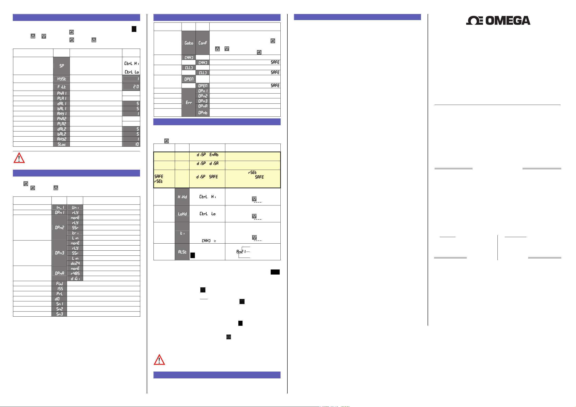
4. SETUP MODE
Note: Configuration must be completed before adjusting Setup parameters.
First select Setup mode from Select mode (refer to section 2). The Setup LED
will light while in Setup mode. Press to scroll through the parameters,
then press or to set the required value.
To exit from Setup mode, hold down and press to return to Select mode.
Note: Parameters displayed depends on how instrument has been configured.
Parameter Lower
Display
Upper Display Adjustment
Range & Description
Default
Value
R/max if
Limit Setpoint value
Scaled Range Minimum to
scaled Range Maximum
=
R/min if
=
Limit Hysteresis
Input Filter Time Constant
High Alarm 1 value R/max
Low Alarm 1 value
Deviation Alarm 1 Value
1 LSD to full span in display units,
on the safe side of the limit SP
OFF or 0.5 to 100.0 secs
(see CAUTION note below)
Scaled Range Minimum to
scaled Range Maximum
±Span from SP in display units
.
R/min
Band Alarm 1 value 1 LSD to span from setpoint
Alarm 1 Hysteresis 1 LSD to full span in display units
High Alarm 2 value R/max
Low Alarm 2 value
Deviation Alarm 2 Value
Scaled Range Minimum to
scaled Range Maximum
±Span from SP in display units
R/min
Band Alarm 2 value 1 LSD to span from setpoint
Alarm 2 Hysteresis 1 LSD to full span in display units
Setup Lock Code 0 to 9999
Note: Operator mode screens follow, without exiting from Setup mode.
CAUTION: An excessively large filter time could significantly delay
detection of a limit condition. Set this value to the minimum required
to remove noise from the process variable
5. PRODUCT INFORMATION MODE
First select Product information mode from Select mode (refer to section 2).
Press to view each parameter. To exit from Product Information mode,
hold down and press to return to Select mode.
Note: These parameters are all read only.
Parameter Lower
Display
Input type Universal input
Option 1 type (fixed) Latching Limit Relay
Option 2 module type
fitted
Option 3 module type
fitted
Auxiliary Option A
module type fitted
Firmware type Value displayed is firmware type number
Firmware issue Value displayed is firmware issue number
Product Revision Level Value displayed is Product Revision level
Date of manufacture
Serial number 1 First four digits of serial number
Serial number 2 Middle four digits of serial number
Serial number 3 Last four digits of serial number
Mm
Mm
MmMm
Upper
Display
Description
No option fitted
Relay output
SSR drive output
Triac output
Linear DC voltage / current output
No option fitted
Relay output
SSR drive output
Linear DC voltage / current output
Transmitter power supply
No option fitted
RS485 communications
Digital Input for remote reset
Manufacturing date code (mmyy)
6. ERROR/FAULT INDICATIONS
Parameter Upper
Display
Instrument
parameters are in
default conditions
Input Over Range
Input Under
Range
Input Sensor
Break
Option 1 Error
Option 2 Error
Option 3 Error
Option A Error
Option B Error
Normal
Normal
Normal
Lower
Display
Configuration & Setup required. This screen is
seen at first turn on, or if hardware
configuration has been changed. Press to
enter the Configuration Mode, next press
or to enter the unlock code number,
then press to proceed
Normal
Process variable input > 5% over-range
as above if Display Strategy =
Normal
Process variable input > 5% under-range
as above if Display Strategy =
Normal
Break detected in process variable input
as above if Display Strategy =
Option 1 module fault
Option 2 module fault
Option 3 module fault
Option A module fault
Option B not used on Limit Controllers
this error is shown if any module is fitted
Description
sensor or wiring
7. OPERATOR MODE
This mode is entered at power on, or accessed from Select mode (see section 2).
Note: All Configuration mode and Setup mode parameters must be set as
required before starting normal operations.
Press to scroll through the parameters.
Upper
Display
PV Value
Limit SP
Value
or
Lower
Display Strategy and
Display
Limit SP
Value
(Blank)
(Blank)
or PV
Value
When Visible
=
(initial screen)
=
(initial screen)
= .
(Initial Screen)
Description
PV and Limit Setpoint values
Read only
Limit Setpoint value
Read only
Displays and PV if Limit
Output is active or and blank
if not active.
Read only
Highest PV value since this
High Limit
Hold
=
parameter was last reset.
To reset, press for 5 seconds,
display =
when reset
Lowest PV value since this
Low Limit
Hold
Exceed Time
Value
Active Alarm
Status
=
Always available
Format mm.ss to 99.59
then mmm.s
(10 sec increments)
Shows
if 999.9
When one or more
alarms are active.
ALM indicator
will also flash
parameter was last reset.
To reset, press for 5 seconds,
display =
when reset
Accumulated time of Limit SP
exceed conditions since this
parameter was last reset.
To reset, press for 5 seconds,
display =
L
when reset
Alarm 2 active
Alarm 1 active
L
Annunciator active
Exceed Condition
An Exceed Condition is when the Process Variable exceeds the Limit Setpoint value
(i.e. PV > SP when set for high limit action, PV < SP for low limit action). The
LED is on during this condition, and is extinguished once it has passed.
Limit Output Function
Limit Output relay(s) de-energise whenever an Exceed condition occurs, causing
the process to shut down. The LED is on when the relay is de-energised.
The relay remains latched off even if the Exceed condition is no longer present.
Only giving a reset instruction (after
energise the relay, allowi ng the process to continue. The LED then turns off.
Limit Annunciator Outputs
An Annunciator output will activate when an Exceed condition occurs, and will
remain active until a reset instruction is received, or the Exceed condition has
passed. Unlike the Limit Output, an Annunciator can be reset even if the Exceed
condition is present. When an Annunciator is active, the LED will flash and the
Alarm Status screen is available.
Resetting Limit Outputs & Annunciators
A reset instruction can be given by pressing the key, via the Digital Input (if
fitted) or via a Comms command if an RS485 Communications module is fitted.
Annunciators will deactivate. Limit Outputs will only re-energise if the Exceed
condition has passed.
CAUTION: Ensure that the cause of the Exceed condition has been
rectified before resetting the Limit Output.
the exceed condition has passed) will re-
8. SERIAL COMMUNICATIONS
Refer to the full user guide (available from your supplier) for details.
9. SPECIFICATIONS
UNIVERSAL INPUT
Thermocouple
Calibration:
PT100 Calibration:
DC Calibration:
Sampling Rate: 4 per second.
Impedance:
Sensor Break
Detection:
Isolation: Isolated from all outputs (except SSR driver).
DIGITAL INPUT
Volt-free(or TTL): Open(2 to 24VDC) =No Reset.
Isolation: Reinforced safety isolation from inputs and other outputs.
OUTPUTS
Limit Relay
Contact Type &
Rating:
Lifetime: >100,000 operations at rated voltage/current.
Isolation: Basic Isolation from universal input and SSR outputs.
Alarm Relays
Contact Type &
Rating:
Lifetime: >500,000 operations at rated voltage/current.
Isolation: Basic Isolation from universal input and SSR outputs.
SSR Driver
Drive Capability:
Isolation: Not isolated from universal input or other SSR driver outputs.
Triac
Operating Voltage: 20 to 280Vrms (47 to 63Hz).
Current Rating: 0.01 to 1A (full cycle rms on-state @ 25°C );
Isolation: Reinforced safety isolation from inputs and other outputs.
DC
Resolution: 8 bits in 250mS (10 bits in 1s typical, >10 bits in >1s typical).
Isolation: Reinforced safety isolation from inputs and other outputs.
Transmitter PSU
Power Rating:
Isolation: Reinforced safety isolation from inputs and other outputs.
SERIAL COMMUNICATIONS
Physical: RS485, at 1200, 2400, 4800, 9600 or 19200 bps.
Protocols: Selectable between Modbus and West ASCII.
Isolation: Reinforced safety isolation from all inputs and outputs.
OPERATING CONDITIONS (FOR INDOOR USE)
Ambient
Temperature:
Relative Humidity: 20% to 95% non-condensing.
Supply Voltage and
Power:
ENVIRONMENTAL
Standards:
EMI:
Safety
Considerations:
Front Panel Sealing: To IP66 (IP20 behind the panel).
PHYSICAL
Front Bezel Size: 1/
Depth Behind Panel:
Weight: 0.21kg maximum.
±0.1% of full range, ±1LSD (±1°C for Thermocouple CJC).
BS4937, NBS125 & IEC584.
±0.1% of full range, ±1LSD.
BS1904 & DIN43760 (0.00385
Ω/Ω
/°C).
±0.1% of full range, ±1LSD.
>10MΩ resistive, except DC mA (5Ω) and V (47kΩ ).
Thermocouple, RTD, 4 to 20 mA, 2 to 10V and 1 to 5V ranges
only. Limi t outputs turn off (goes into Exceed condition), high
alarms activate for thermocouple/RTD sensor break, low
alarms activate for mA /V DC sensor break.
Universal input must not be connected to operator accessible
circuits if relay outputs are connected to a hazardous voltage
source. Supplementary insulation or input grounding would
then be required.
Closed(<0.8VDC) = Reset (edge triggered).
Latching limit control relay. Single pole double throw (SPDT);
5A resistive at 120/240VAC. Slot 1 position fixed for this
function, optional function for Slot 2 & 3 relay modules,
Slot 2 or 3 position non-latching alarm relay.
Single pole double throw (SPDT); 2A resistive at 120/240VAC
SSR drive voltage >10V into 500Ω min.
derates linearly above 40°C to 0.5A @ 80°C.
20 to 28V DC (24V nominal) into 910Ω minimum resistance.
0°C to 55°C (Operating), –20°C to 80°C (Storage).
100 to 240VAC ±10%, 50/60Hz, 7.5VA
(for mains powered versions), or
20 to 48VAC 50/60Hz 7.5VA or 22 to 65VDC 5W
(for low voltage versions).
CE, FM 3545, 1998
Complies with EN61326 (Susceptibility & Emissions).
Complies with EN61010-1.
Pollution Degree 2, Installation Category II.
Din = 48 x 48mm, 1/8 Din = 96 x 48mm,
16
1
/4 Din = 96 x 96mm.
1
/
Din = 110mm, , 1/8 & 1/4 Din = 100mm.
16
™
omega.com [email protected]
Servicing North America:
U.S.A. Omega Engineering, Inc.
Headquarters: Toll-Free: 1-800-826-6342 (USA & Canada only)
Customer Service: 1-800-622-2378 (USA
& Canada only) Engineering Service:
1-800-872-9436 (USA & Canada only)
e-mail: [email protected]
For Other Locations Visit omega.com/worldwide
It is the policy of OMEGA Engineering, Inc. to comply with all worldwide safety and EMC/EMI regulations that apply. OMEGA
is constantly pursuing certification of its products to the European New Approach Directives. OMEGA will add the CE mark
to every appropriate device upon certification.
The information contained in this document is believed to be correct, but OMEGA accepts no liability for any errors it
and reserves the right to alter specifications without notice.
contains,
WARNING:
These products are not designed for use in, and should not be used for, human applications.
OMEGA ENGINEERING, INC. warrants this unit to be free of defects in materials and workmanship for a period
of 37 months from date of purchase. OMEGA’s WARRANTY adds an additional one (1) month grace period to
the normal three (3) year product warranty to cover handling and shipping time. This ensures that
OMEGA’s customers receive maximum coverage on each product.
If the unit malfunctions, it must be returned to the factory for evaluation. OMEGA’s Customer Service Department will issue
an Authorized Return (AR) number immediately upon phone or written request. Upon examination by OMEGA, if the unit is
found to be defective, it will be repaired or replaced at no charge. OMEGA’s WARRANTY does not apply to defects resulting
from any action of the purchaser, including but not limited to mishandling, improper interfacing, operation outside of design
limits, improper repair, or unauthorized modification. This WARRANTY is VOID if the unit shows evidence of having been
tampered with or shows evidence of having been damaged as a result of excessive corrosion; or current, heat, moisture or
vibration; improper specification; misapplication; misuse or other operating conditions outside of OMEGA’s control.
Components in which wear is not warranted, include but are not limited to contact points, fuses, and triacs.
OMEGA is pleased to offer suggestions on the use of its various products. However, OMEGA
neither assumes responsibility for any omissions or errors nor assumes liability for any damages
that result from the use of its products in accordance with information provided by OMEGA,
either verbal or written. OMEGA warrants only that the parts manufactured by the company will
be as specified and free of defects. OMEGA MAKES NO OTHER WARRANTIES OR
REPRESENTATIONS OF ANY KIND WHATSOEVER, EXPRESSED OR IMPLIED, EXCEPT THAT OF
TITLE, AND ALL IMPLIED WARRANTIES INCLUDING ANY WARRANTY OF MERCHANTABILITY AND
FITNESS FOR A PAR TICULAR PURPOSE ARE HEREBY DISCLAIMED. LIMITATION OF LIABILITY: The
remedies of purchaser set forth herein are exclusive, and the total liability of OMEGA with respect
to this order, whether based on contract, warranty, negligence, indemnification, strict liability or
otherwise, shall not exceed the purchase price of the component upon which liability is based. In
no event shall OMEGA be liable for consequential, incidental or special damages.
CONDITIONS: Equipment sold by OMEGA is not intended to be used, nor shall it be used: (1) as a “Basic
Component” under 10 CFR 21 (NRC), used in or with any nuclear installation or activity; or (2) in medical
applications or used on humans. Should any Product(s) be used in or with any nuclear installation or activity,
medical application, used on humans, or misused in any way, OMEGA assumes no responsibility as set forth in
our basic WARRANTY / DISCLAIMER language, and, additionally, purchaser will indemnify OMEGA and hold
OMEGA harmless from any liability or damage whatsoever arising out of the use of the Product(s) in such a
manner.
Direct all warranty and repair requests/inquiries to the OMEGA Customer Service Department. BEFORE
RETURNING ANY PRODUCT(S) TO OMEGA, PURCHASER MUST OBTAIN AN AUTHORIZED RETURN (AR)
NUMBER FROM OMEGA’S CUSTOMER SERVICE DEPARTMENT (IN ORDER TO AVOID PROCESSING DELAYS).
The assigned AR number s hould then be marked on the outside of the return package and on any
correspondence.
The purchaser is responsible for shipping charges, freight, insurance and proper packaging to prevent
breakage in transit.
FOR WARRANTY RETURNS, please have the
following information available BEFORE contacting
OMEGA:
1. Purchase Order number under which the product
was PURCHASED,
2. Model and serial number of the product under
warranty, and
3. Repair instructions and/or specific problems
relative to the product.
OMEGA’s policy is to make running changes, not model changes, whenever an improvement is possible.
This affords our customers the latest in technology and engineering.
OMEGA is a trademark of OMEGA ENGINEERING, INC
© Copyright 2018 OMEGA ENGINEERING, INC. All rights reserved. This document may not be copied,
photocopied, reproduced, translated, or reduced to any electronic medium or machine-readable form, in
whole or in part, without the prior written consent of OMEGA ENGINEERING, INC.
Where Do I Find E
WARRANTY/DISCLAIMER
RETURN REQUESTS / INQUIRIES
FOR NON-WARRANTY REPAIRS,
current repair charges. Have the following
information available BEFORE contacting OMEGA:
1. Purchase Order number to cover the COST of the
repair,
2. Model and serial number of the product, and
3. Repair instructions and/or specific problems
relative to the product.
.
verything I Need for Process
Measurement and Control? OMEGA…Of Course!
Shop online at omega.com
TEMPERATURE
Thermocouple, RTD & Thermistor Probes, Connectors,
Panels & Assemblies
Wire: Thermocouple, RTD & Thermistor
Calibrators & Ice Point References
Recorders, Controllers & Process Monitors
Infrared Pyrometers
PRESSURE, STRAIN AND FORCE
Transducers & Strain Gages
Load Cells & Pressure Gages
Displacement Transducers
Instrumentation & Accessories
FLOW/LEVEL
Rotameters, Gas Mass Flowmeters & Flow Computers
Air Velocity Indicators
Turbine/Paddlewheel Systems
Totalizers & Batch Controllers
pH/CONDUCTIVITY
pH Electrodes, Testers & Accessories
Benchtop/Laboratory Meters
Controllers, Calibrators, Simulators & Pumps
Industrial pH & Conductivity Equipment
DATA ACQUISITION
Data Acquisition & Engineering Software
Communications-Based Acquisition Systems
Plug-in Cards for Apple, IBM & Compatibles
Data Logging Systems
Recorders, Printers & Plotters
HEATERS
Heating Cable
Cartridge & Strip Heaters
Immersion & Band Heaters
Flexible Heaters
Laboratory Heaters
ENVIRONMENTAL
MONITORING AND CONTROL
Metering & Control Instrumentation
Refractometers
Pumps & Tubing
Air, Soil & Water Monitors
Industrial Water & Wastewater Treatment
pH, Conductivity & Dissolved Oxygen Instruments
Fax: (203) 359-7700 Tel: (203) 359-1660
consult OMEGA for
M5123/0518
 Loading...