

Page 1
TM
User’s Guide
Shop online at
omega.com
e-mail: [email protected]
For latest product manuals:
www.omegamanual.info
MADE IN UNITED KINGDON
CN2516, CN2508, CN2504
Limit Controllers
Page 2

www.omega.com [email protected]
Servicing North America:
U.S.A.: Omega Engineering, Inc., One Omega Drive, P.O. Box 4047
Stamford, CT 06907-0047 USA
Toll-Free: 1-800-826-6342 (USA & Canada only)
Customer Service: 1-800-622-2378 (USA & Canada only)
Engineering Service: 1-800-872-9436 (USA & Canada only)
Tel: (203) 359-1660 Fax: (203) 359-7700
e-mail: [email protected]
For Other Locations Visit omega.com/worldwide
The information contained in this document is believed to be correct, but OMEGA accepts no liability for any errors it contains, and
reserves the right to alter specifications without notice.
WARNING: These products are not designed for use in, and should not be used for, human applications.
Page 3
Limit Devices–CN2516, CN2508 and CN2504 Product Manual
Users’ Manual
CN2516, CN2508 and CN2504
This manual supplements the Concise Product manual supplied with each instrument at the
time of shipment. Information in this installation, wiring and operation manual is subject to
change without notice.
Note:
It is strongly recommended that applications incorporate a high or low limit protective
device, which will shut down the equipment at a preset process condition in order to
prevent possible damage to property or products.
WARNING:
THE INTERNATIONAL HAZARD SYMBOL IS INSCRIBED ADJACENT TO THE REAR
CONNECTION TERMINALS. IT IS IMPORTANT TO READ THIS MANUAL BEFORE
INSTALLING OR COMMISSIONING THE UNIT.
Products covered by this manual are suitable for Indoor use, Installation Category II,
Pollution category 2 environments
Products covered in this issue of the manual:
CN2516, CN2508 and CN2504 series limit devices.
Page i
Page 4

Limit Devices–CN2516, CN2508 and CN2504 Product Manual
Contents Page Number:
Contents...................................................................................................................................ii
How to use this manual..........................................................................................................vi
1 Introduction ....................................................................................................................................... 1
2 Installation ......................................................................................................................................... 2
Unpacking ............................................................... ..................................................................................... 2
Installation ......................................................................... .................................................................... ....... 2
Panel Cut-outs ............................................................................................................................................. 3
Panel-Mounting ..................................................................... ....................................................................... 3
3 Plug-in Options ................................................................................................................................. 5
Options Modules and Functions ................................................................................................................. .. 5
Auto Detection of Option Modules ................................................................................................................ 5
Preparing to Install or Remove Options Modules ......................................................................................... 6
Replacing the Instrument in its Housing ....................................................................................................... 9
4 Wiring Instructions ......................................................................................................................... 10
Installation Considerations ......................................................................................................................... 10
AC Power Wiring - Neutral (for 100 to 240V AC versions) ......................................................................... 10
Wire Isolation ............................................................................................................................................. 10
Use of Shielded Cable ............................................................................................................................... 11
Noise Suppression at Source ..................................................................................................................... 11
Sensor Placement (Thermocouple or RTD) ............................................................................................... 12
Thermocouple Wire Identification Chart ..................................................................................................... 12
Connections and Wiring ............................................................................................................................. 13
Power Connections - Mains Powered Instruments ............................................................................. 15
Power Connections - 24/48V AC/DC Powered Instruments ............................................................... 15
Universal Input Connections - Thermocouple (T/C) ........................................................................... 16
Universal Input Connections – PT100 (RTD) input ............................................................................. 16
Universal Input Connections - Linear Volt, mV or mA input ................................................................ 17
Option Slot 1 – Relay Output Module ................................................................................................. 17
Option Slot 2 - Relay Output Module .................................................................................................. 18
Option Slot 2 - SSR Driver Output Module ......................................................................................... 18
Option Slot 2 - Triac Output Module ................................................................................................... 18
Option Slot 2 - Linear Voltage or mADC Output module .................................................................... 19
Option Slot 3 - Relay Output Module .................................................................................................. 19
Option Slot 3 - SSR Driver Output Module ......................................................................................... 19
Option Slot 3 - Linear Voltage or mADC Output module .................................................................... 20
Option Slot 3 - Transmitter Power Supply Module .............................................................................. 20
Option Slot A Connections - RS485 Serial Communications Module ................................................. 20
Option Slot A Connections - Digital Input Module ............................................................................... 21
5 Powering Up .................................................................................................................................... 22
Page ii
Page 5

Limit Devices–CN2516, CN2508 and CN2504 Product Manual
Powering Up Procedure ............................................................................................................................. 22
Overview of Front Panel ............................................................................................................................ 22
Displays ..................................................................................................................................................... 23
Keypad ...................................................................................................................................................... 23
LED Functions ........................................................................................................................................... 23
6 Messages and Error Indications ................................................................................................... 24
7 Instrument Operation Modes ......................................................................................................... 25
Select Mode ............................................................................................................................................... 25
Entry into the Select Mode ................................................................................................................. 25
Navigating in Select Mode ................................................................................................................. 25
Unlock Codes ............................................................................................................................................ 25
Navigating in the Product Information Mode ...................................................................................... 26
Entry and Navigating in Lock Code View Mode ................................................................................. 27
8 CN2516, CN2508 & CN2504 – Model Group ................................................................................. 28
CN2516, CN2508 & CN2504 Limit Devices - Configuration Mode ............................................................. 28
Entry into the Configuration Mode ...................................................................................................... 28
Scrolling through Parameters and Values .......................................................................................... 28
Changing Parameter Values .............................................................................................................. 28
CN2516, CN2508 & CN2504 Limit Devices – Setup Mode ........................................................................ 34
Entry into the Setup Mode .................................................................................................................. 34
Scrolling through Parameters & Values ............................................................................................. 34
Changing Parameter Values .............................................................................................................. 34
CN2516, CN2508 & CN2504 Limit Devices - Operator Mode .................................................................... 36
Navigating in Operator Mode ............................................................................................................. 36
Limit Setpoint Adjustment .......................................................................................................................... 37
Exceed Condition ....................................................................................................................................... 37
Limit Output Function ................................................................................................................................. 37
Limit Annunciator Outputs .......................................................................................................................... 37
Resetting Limit Outputs & Annunciators ..................................................................................................... 37
Using the Reset Key to Reset Limit Outputs & Annunciators ............................................................ 37
Resetting Limit Hold and Exceed Time ...................................................................................................... 37
CN2516, CN2508 & CN2504 Devices – Serial Communications Parameters ............................................ 38
Bit Parameters ................................................................................................................................... 38
Word Parameters ............................................................................................................................... 38
9 Modbus Serial Communications .................................................................................................. 42
Physical Layer ........................................................................................................................................... 42
Link Layer .................................................................................................................................................. 43
Device Addressing ..................................................................................................................................... 44
Supported Modbus Functions .................................................................................................................... 44
Function Descriptions ................................................................................................................................ 44
Read Coil/Input Status (Function 01 / 02) .......................................................................................... 45
Page iii
Page 6

Limit Devices–CN2516, CN2508 and CN2504 Product Manual
Read Holding/Input Registers (Function 03 / 04) ................................................................................ 45
Force Single Coil (Function 05) .......................................................................................................... 46
Pre-Set Single Register (Function 06) ................................................................................................ 46
Loopback Diagnostic Test (Function 08) ............................................................................................ 46
Pre-Set Multiple Registers (Function 10 Hex) .................................................................................... 47
Exception Responses ........................................................................................................................ 47
10 ASCII Communications ............................................................................................................... 48
Physical Layer ............................................................................................................................................ 48
Device Addressing ..................................................................................................................................... 48
Session Layer ....................................................................................................................................... ..... 48
Type 1 Message ................................................................................................................................. 49
Type 2 Message ................................................................................................................................. 50
Type 3 Message ................................................................................................................................. 50
Type 4 Message ................................................................................................................................. 51
Error Response ......................................................................................................................................... . 51
11Calibration Mode ............................................................................................................................ 52
Equipment Required For Checking or Calibrating the Universal Input ........................................................ 52
Calibration Check ....................................................................................................................................... 52
Recalibration Procedure ............................................................................................................................. 53
12Appendix 1 – Glossary ................................................................................................................... 54
Alarm Hysteresis Type: Limit Device Parameter .................................................................................... 54
Alarm Operation Type: Limit Device Definition ........................................................................................ 55
Annunciator Type: Limit Device Definition ..................................................... .......................................... 56
Band Alarm 1 Value Type: Limit Device Parameter ................................................................... .............. 56
Band Alarm 2 Value Type: Limit Device Parameter ................................................................... .............. 56
Communications Write Enable Type: Limit Device Definition .................................................................. 56
CPU Type: Limit Device Definition ......................................................................................................... 56
Deviation Alarm 1 Value Type Type: Limit Device Parameter ................................................................. 56
Deviation Alarm 2 Value Type: Limit Device Parameter .......................................................................... 56
Display Strategy Type: Limit Device Parameter ...................................................................................... 57
Exceed Condition Type: Limit Device Definition ...................................................................................... 57
Exceed Time Type: Limit Device Definition ............................................................................................. 57
Input Filter Time Constant Type: Limit Device Parameter ....................................................................... 57
Input Range Type: Limit Device Definition ................................................. .............................................. 57
Input Span Type: Limit Device Definition ............................................................ ..................................... 57
Latching Relay Type: Limit Device Definition .......................................................................................... 57
LED Type: Limit Device Definition ......................................................................................................... 57
Limit Device Type: Limit Device Definition ........................................................................ ....................... 58
Limit Hysteresis Type: Limit Device Definition ......................................................... ................................ 58
Limit Setpoint Type: Limit Device Definition ............................................................................................ 58
Lock Codes Type: Limit Device Parameter ............................................................................................ 58
Page iv
Page 7

Limit Devices–CN2516, CN2508 and CN2504 Product Manual
mADC
PLC Type: Limit Device Definition ..................................................................................................... 59
Process High Alarm 1 Value Type: Limit Device Parameter ................................................................... 59
Process High Alarm 2 Value Type: Limit Device Parameter ................................................................... 59
Process Low Alarm 1 Value Type: Limit Device Parameter ................................................................... 59
Process Low Alarm 2 Value Type: Limit Device Parameter ................................................................... 59
Process Variable (PV) Type: Limit Device Definition .................................................................. ............. 59
Process Variable Offset Type: Limit Device Parameter .......................................................................... 60
Retransmit Output Type: Limit Device Definition ............................................................................ ........ 60
Retransmit Output 2 Scale Maximum Type: Limit Device Parameter ...................................................... 60
Retransmit Output 2 Scale Minimum Type: Limit Device Parameter ...................................................... 60
Retransmit Output 3 Scale Maximum Type: Limit Device Parameter ..................................................... 60
Retransmit Output 3 Scale Minimum Type: Limit Device Parameter ...................................................... 60
Scale Range Upper Limit Type: Limit Device Parameter........................................................................ 60
Scale Range Lower Limit Type: Limit Device Parameter........................................................................ 61
Serial Communications Option Type: Limit Device Definition .................................................................. 61
Triac Type: Limit Device Definition .................................................................................................... 61
Type: Limit Device Definition ...................................................................................................... 59
13Appendix 2 - Specifications ........................................................................................................... 62
Universal Input ........................................................................................................................................... 62
General Input Specifications .............................................................................................................. 62
Thermocouple ....................................................... ............................................................................. 62
Thermocouple Ranges Available ............................................................................................................... 62
Thermocouple Performance ....................................................................................................................... 63
Resistance Temperature Detector (RTD) ........................................................................................... 63
RTD Ranges Available ............................................................................................................................... 63
RTD Performance ...................................................................................................................................... 64
DC Linear ........................................................................................................................................... 64
DC Linear Ranges Available ...................................................................................................................... 64
DC Linear Performance ............................................................................................................................. 64
Digital Inputs .............................................................................................................................................. 65
Output Module Types ......................................................................................................................... 65
Specifications of Output Types .......................................................................................................... 65
Process Alarms .......................................................................................................................................... 67
Digital Communications ............................................................................................................................. 67
Reference Conditions ................................................................................................................................ 67
Operating Conditions ................................................................................................................................. 67
Standards .................................................................................................................................................. 68
Physical Specifications .............................................................................................................................. 68
Page v
Page 8

Limit Devices–CN2516, CN2508 and CN2504 Product Manual
How to use this manual
This manual is structured to give easy access to the information required for all aspects of the
installation and use and of the products:
Section 1: Introduction - A brief description of the product range.
Section 2: Installation - Unpacking, installing and panel mounting instructions.
Section 3: Plug-in Options - Installation of the plug-in option modules.
Section 4: Wiring Guidelines - Guidance on good wiring practice, noise avoidance, wiring
diagrams and input/output connections.
Section 5: Powering Up - Powering up procedure and descriptions of displays & switches.
Section 6: Messages & Error Indications - Display Messages and fault indications.
Section 7: Operation Modes - Describes operating modes common across the range. These
include Select Mode for gaining access to the Setup and Configuration menus and the Product
information menus.
Section 8: CN2516, CN2508 & CN2504 Model Group - Describes unique operating features of
these limit controllers. It covers the Configuration, Setup & Operator menus, and Communications
parameters, adjusting the Limit Setpoint and resetting the Limit Output.
Section 09: Modbus Serial Communications - Details the physical layer and message formats
used for the Modbus communications protocol common to all products in the range.
Section 10: ASCII Serial Communications - Details the physical layer and message formats used
for the ASCII serial communications protocol available on some products.
Section 11: Calibration Mode - Step-by-step instructions to calibrate the instrument. This section
is intended for use by suitably qualified personnel.
Appendix 1: Glossary - Explanations of the terms used and product features.
Appendix 2: Specification - Technical specifications for all products in the range.
Page vi
Page 9

Limit Devices–CN2516, CN2508 and CN2504 Product Manual
1 Introduction
These instruments are microprocessor based limit devices. They can measure process
variables such as temperature, pressure, flow and level from a variety of inputs. Models are
available in three sizes.
96mm front).
The operating voltage is either 100-240V at 50/60 Hz or 24V-48V AC/DC depending on the
model purchased. EEPROM technology protects against data or configuration loss during
power outages.
Inputs are user configurable for connection to thermocouple and RTD probes, as well as linear
process signal types such as mVDC, VDC or mADC. Output options include relays, SSR
drivers, triacs or linear mV/voltage modules. These can be used for alarms or retransmission of
the process variable to external devices such as data recorders or PLC’s. A Transmitter Power
Supply option module can provide an unregulated 24V DC (22mA) auxiliary output voltage for
external signal transmitters.
Alarm indication is standard on all instruments. Alarms may be set as process high or low,
deviation (active above or below Limit setpoint) or band (active both above and below setpoint).
These alarms can be linked to any suitable output. Alarm status is indicated by LED’s or the
alarm status screen.
1
/16 DIN (48 x 48mm front), 1/8 DIN (48 x 96mm front) and 1/4 DIN (96 x
Limit Controllers shut down a process in order to prevent possible damage to equipment or
products. They have a latching relay, which cannot be reset until the process is in a safe
condition. Limit controllers work independently of the normal process controller and have
approvals for critical applications.
Introduction Page 1
Page 10
Limit Devices–CN2516, CN2508 and CN2504 Product Manual
1
/
1
/
/
8
2 Installation
Unpacking
1. Remove the product from its packing. Retain the packing for future use, in case it is
necessary to transport the instrument to a different site or to return it to the supplier for
repair/testing.
2. The instrument is supplied with a panel gasket and push fit fixing strap. A single sheet
concise manual is also supplied in one or more languages. Examine the delivered items
for damage or defects. If any are found, contact your supplier immediately.
Installation
CAUTION:
Installation and configuration should be performed only by personnel who are
technically competent and authorised to do so. Local regulations regarding
electrical installation and safety must be observed.
- DIN &
1
- DIN Instruments
- DIN Instruments
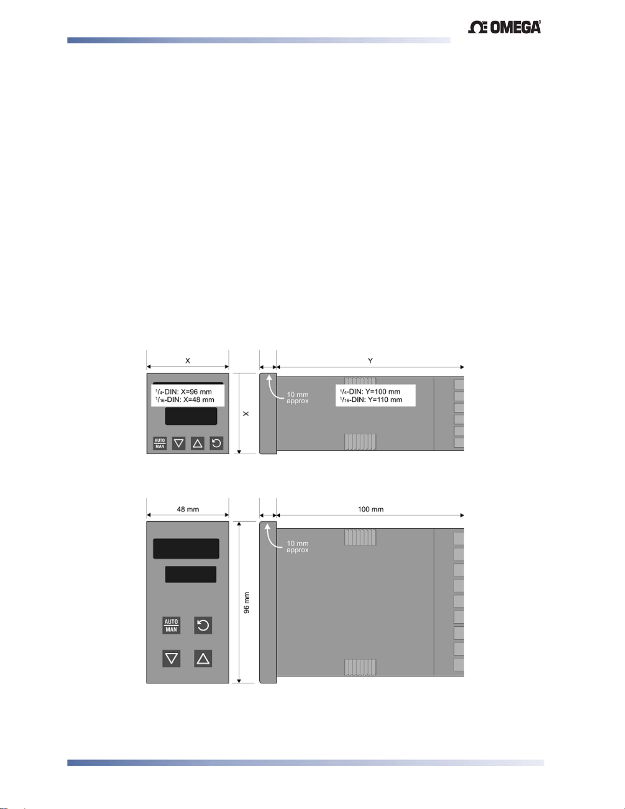
Figure 1. Main dimensions
Installation Page 2
Page 11
Limit Devices–CN2516, CN2508 and CN2504 Product Manual
Panel Cut-outs
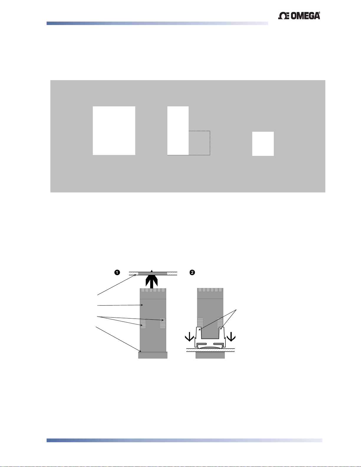
The mounting panel must be rigid and may be up to 6.0mm (0.25 inches) thick. The cut-outs
required for the instruments are shown below.
1
/16 DIN
45mm
+0.5 –0.0
45mm
+0.5 –0.0
92mm
+0.5 –0.0
1
/4 DIN
92mm
+0.5 –0.0
1
/8 DIN
45mm +0.5 –0.0
92mm
+0.5 –0.0
Figure 2. Panel cut-out sizes
Panel-Mounting
CAUTION:
Insure the inside of the panel is with the instruments operating temperature and that
there is adequate air flow to prevent overheating.
Slide mounting clamp over the
instrument housing, towards rear face of
Mounting Panel
Instrument Housing
Ratchets
Gasket
mounting panel, until the tongues
engage in ratchets and instrument is
clamped in position
Hold firmly in position
(apply pressure to bezel only)
Figure 3. Panel-Mounting the device
CAUTION:
For an effective IP66 seal against dust and moisture, ensure
gasket is well compressed against the panel, with the 4 tongues located in
the same ratchet slot..
Installation Page 3
.
Page 12

Limit Devices–CN2516, CN2508 and CN2504 Product Manual
Once the instrument is installed in its mounting panel, it may be subsequently removed from its
housing, if necessary, as described in the Fitting and Removing Option Modules section.
Instruments may be mounted side-by-side in a multiple installation, but instrument to panel
moisture and dust sealing will be compromised. The cut-out width (for n instruments) is shown
below.
1
/8 - & 1/16 - DIN Instruments: (48n - 4) mm or (1.89n - 0.16) inches
1
/4 - DIN Instruments: (96n - 4) mm or (3.78n - 0.16) inches
If panel sealing must be maintained, mount each instrument into an individual cut-out with 6mm
or more clearance between the edges of the holes.
Note:
The mounting clamp tongues may engage the ratchets either on the sides or the
top/bottom faces of the Instrument housing. When installing several Instruments side-byside in one cut-out, use the ratchets on the top/bottom faces.
Installation Page 4
Page 13
Limit Devices–CN2516, CN2508 and CN2504 Product Manual
3 Plug-in Options
Options Modules and Functions
A range of plug-in option modules is available to add additional input, output and
communication functions to the instruments in the range. These modules can be either preinstalled at the time of manufacture, or retrofitted in the field.
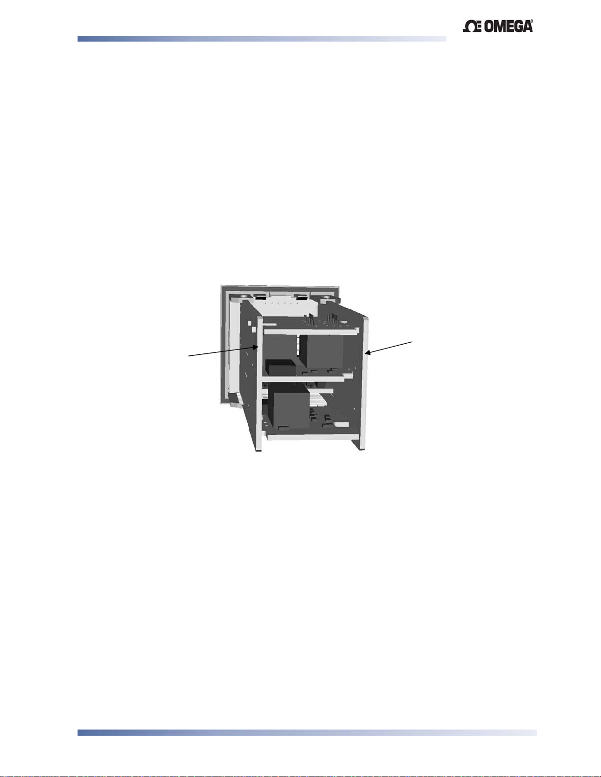
The modules are installed between the instruments main circuit boards into the four option
slots. These are designated as Slots 1, 2, 3, and A. Installation is detailed below.
Note:
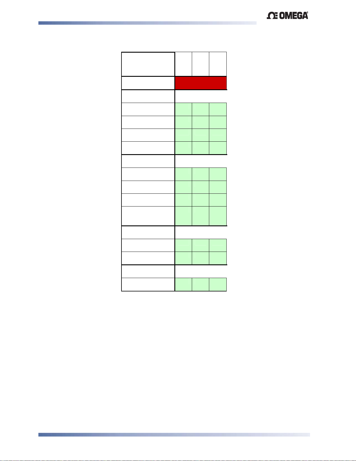
Slot 1 modules are fitted with a fixed limit relay. Slot 2 & 3 modules cannot be fitted into
Slot 1. Some Slot 2 &3 modules should only be fitted into one of the two slots. This is
detailed in the - Option Module vs. Model Matrix below.
PSU BOARD
CPU BOARD
Figure 4. Typical rear view (uncased) & main board positions
Auto Detection of Option Modules
The instrument automatically detects which option modules have been fitted into each slot.
In Configuration Mode, the menus will change to reflect the options compatible with the
hardware fitted. The modules fitted can be viewed in the products information menu, as detailed
in the Product Information Mode section of this manual.
Plug-in Options Page 5
Page 14
Limit Devices–CN2516, CN2508 and CN2504 Product Manual
Table 1. Option Module vs. Model Matrix
MODULE PART
NUMBER
CN2516
CN2508
& Function
OPTION
SLOT 1
OPTION
SLOT 2
CN2500X-R
Relay
CN2500X-DC
SSR Driver
CN2500X-T
Triac
CN2300X-F
Linear mA/V DC
OPTION
SLOT 3
CN2500X-R
Relay
CN2500X-DC
SSR Driver
CN2300X-F
Linear mA/V DC
CN2300X-TPS
Transmitter Power
Supply
OPTION
SLOT A
CN2300X-485
RS485 Comms
CN2300X-DI
Digital Input
SOFTWARE &
ACCESSORIES
CN2500-SOFT
Config Software
Fitted with fixed
Limit Relay
CN2504
Preparing to Install or Remove Options Modules
CAUTION:
Before removing the instrument from its housing, insure that all power has been
removed from the rear terminals.
1. Remove the instrument from its housing by gripping the side edges of the front panel
(there is a finger grip on each edge) and pull the instrument forwards. This will release
the instrument from the rear connectors in the housing and will give access to the PCBs.
2. Take note of the orientation of the instrument for subsequent replacement into the
housing. The positions of the main and option PCBs in the instrument are shown below.
Plug-in Options Page 6
Page 15
Limit Devices–CN2516, CN2508 and CN2504 Product Manual
p
Removing/Replacing Option Modules
With the instrument removed from its housing:
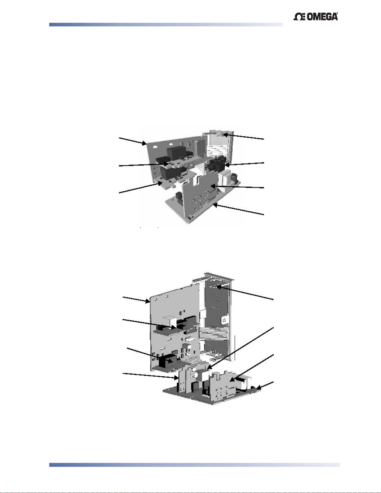
1. To remove or replace modules into Option Slot A, it is necessary to gently separate the
CPU and PSU PCBs. This is achieved by detaching the main boards (PSU and CPU)
from the front molding by lifting first the upper and then lower mounting struts as shown.
This frees the boards from the front. If only Option slots 2 or 3 are to be changed, this
stage is not required as these slots are accessible without separating the main boards
from the front.
CPU PCB
Option Slot 1
(Fixed Limit Relay)
Mounting Struts
Option Slot A
Option Slot 3
tion Slot 2
O
PSU PCB
Figure 5. Location of Option Slots -
1
/16 DIN Instruments
CAUTION:
Take care not to put undue stress on the ribbon cable attaching the display and CPU
boards.
CPU PCB
Option Slot B
(Do not use)
Option Slot 2
Option Slot 1
(Fixed Limit Relay)
Mounting Struts
Option Slot A
Option Slot 3
PSU PCB
Figure 6. Location of Option Slots - 1/8 & 1/4 DIN Instruments
CAUTION:
Take care not to put undue stress on the ribbon cable attaching the display and
CPU boards.
Plug-in Options Page 7
Page 16
Limit Devices–CN2516, CN2508 and CN2504 Product Manual
(
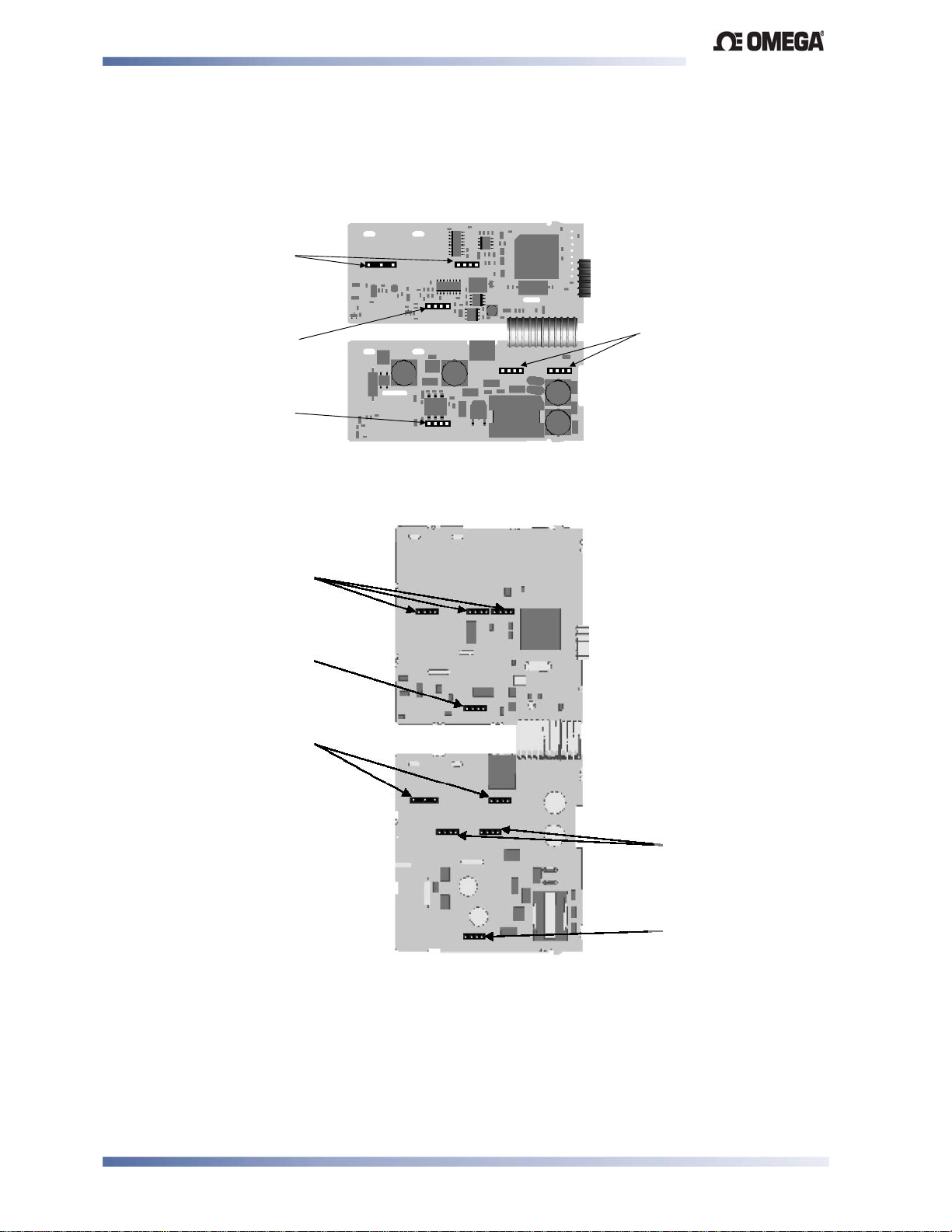
2. Remove or fit the modules into the Option slots as required. The location of the
connectors is shown below. Tongues on each option module locate into slots cut into the
main boards, opposite each of the connectors.
Figure 7. Option Module Connectors -
1
/16 DIN Instruments
Option Slot 1-(Fixed Limit
Relay)
ConnectorsPL7&PL8
Option Slot 2
Connector PL4A
Option Slot A
Connectors PL5 & PL6
Option Slot 3
Connector PL4B
CAUTION:
Check for correct orientation of the modules and that all pins locate correctly into
the socket.
Option Slot B
(Not Used on Limit
Controllers)
Option Slot 2
Connector PL4A
Option Slot 1
Fixed Limit Relay)
Option Slot A
Connectors PL5 & PL6
Option Slot 3
Connectors PL4B
Figure 8. Option Module Connectors - 1/8 & 1/4 DIN Instruments
CAUTION:
Check for correct orientation of the modules and that all pins locate correctly into
the socket
Plug-in Options Page 8
Page 17

Limit Devices–CN2516, CN2508 and CN2504 Product Manual
Replacing the Instrument in its Housing
With the required option modules correctly located into their respective positions the instrument
can be replaced into its housing as follows:
1. If required, move the CPU and PSU boards back together, taking care to locate the
option module tongues into the slots in the board opposite. Hold the main boards
together while relocating them back into the mounting struts on the front panel.
2. Align the CPU and PSU PCBs with their guides and connectors in the housing.
3. Slowly and firmly, push the instrument in position.
CAUTION:
Insure that the instrument is correctly orientated. A mechanical stop will operate if
an attempt is made to insert the instrument in the wrong orientation, this stop MUST
NOT be over-ridden.
Plug-in Options Page 9
Page 18

Limit Devices–CN2516, CN2508 and CN2504 Product Manual
4 Wiring Instructions
Electrical noise is a phenomenon typical of industrial environments. As with any
instrumentation, these guidelines should be followed to minimize the effect of noise.
Installation Considerations
Ignition transformers, arc welders, mechanical contact relays and solenoids are all common
sources of electrical noise in an industrial environment and therefore the following guidelines
MUST be followed.
1. If the instrument is being installed in existing equipment, the wiring in the area should be
checked to insure that good wiring practices have been followed.
2. Noise-generating devices such as those listed should be mounted in a separate
enclosure. If this is not possible, separate them from the instrument, by the largest
distance possible.
3. If possible, eliminate mechanical contact relays and replace with solid-state relays. If a
mechanical relay being powered by an output of this instrument cannot be replaced, a
solid-state relay can be used to isolate the instrument.
4. A separate isolation transformer to feed only the instrumentation should be considered.
The transformer can isolate the instrument from noise found on the AC power input.
AC Power Wiring - Neutral (for 100 to 240V AC versions)
It is good practice to ensure that the AC neutral is at or near ground (earth) potential. A proper
neutral will help insure maximum performance from the instrument.
Wire Isolation
Four voltage levels of input and output wiring may be used with the unit:
1. Analogue input or output (for example thermocouple, RTD, VDC, mVDC or mADC)
2. Relays & Triac outputs
3. SSR Driver outputs
4. AC power
CAUTION:
The only wires that should run together are those of the same category.
If any wires need to run parallel with any other lines, maintain a minimum space of 150mm
between them.
If wires MUST cross each other, insure they do so at 90 degrees to minimize interference.
Connections Page 10
Page 19
Limit Devices–CN2516, CN2508 and CN2504 Product Manual
Use of Shielded Cable
All analogue signals must use shielded cable. This will help eliminate electrical noise induction
on the wires. Connection lead length must be kept as short as possible keeping the wires
protected by the shielding. The shield should be grounded at one end only. The preferred
grounding location is at the sensor, transmitter or transducer.
Noise Suppression at Source
Usually when good wiring practices are followed, no further noise protection is necessary.
Sometimes in severe electrical environments, the amount of noise is so great that it has to be
suppressed at source. Many manufacturers of relays, contactors, etc supply ‘surge
suppressors' which mount on the noise source. For those devices that do not have surge
suppressors supplied, Resistance-Capacitance (RC) networks and/or Metal Oxide Varistors
(MOV) may be added.
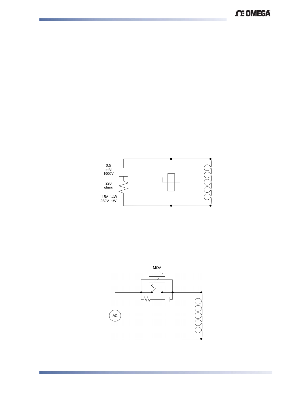
Inductive coils: - MOVs are recommended for transient suppression in inductive coils,
connected in parallel and as close as possible to the coil. Additional protection may be provided
by adding an RC network across the MOV.
Figure 9. Transient suppression with inductive coils
Contacts: - Arcing may occur across contacts when they open and close. This results in
electrical noise as well as damage to the contacts. Connecting a properly sized RC network
can eliminate this arc.
For circuits up to 3 amps, a combination of a 47 ohm resistor and 0.1 microfarad capacitor
(1000 volts) is recommended. For circuits from 3 to 5 amps, connect two of these in parallel.
Figure 10. Contact noise suppression
Connections Page 11
Page 20
Limit Devices–CN2516, CN2508 and CN2504 Product Manual
Sensor Placement (Thermocouple or RTD)
If the temperature probe is to be subjected to corrosive or abrasive conditions, it must be
protected by an appropriate thermowell. The probe must be positioned to reflect true process
temperature:
1. 1. In a liquid media - the most agitated area
2. 2. In air - the best circulated area
CAUTION:
The placement of probes into pipe work some distance from the heating vessel
leads to transport delay, which results in poor control.
For a two wire RTD a wire link should be used in place of the third wire. Two wire RTDs must
only be used with lead lengths less than 3 metres. Use of three wire RTDs is strongly
recommended.
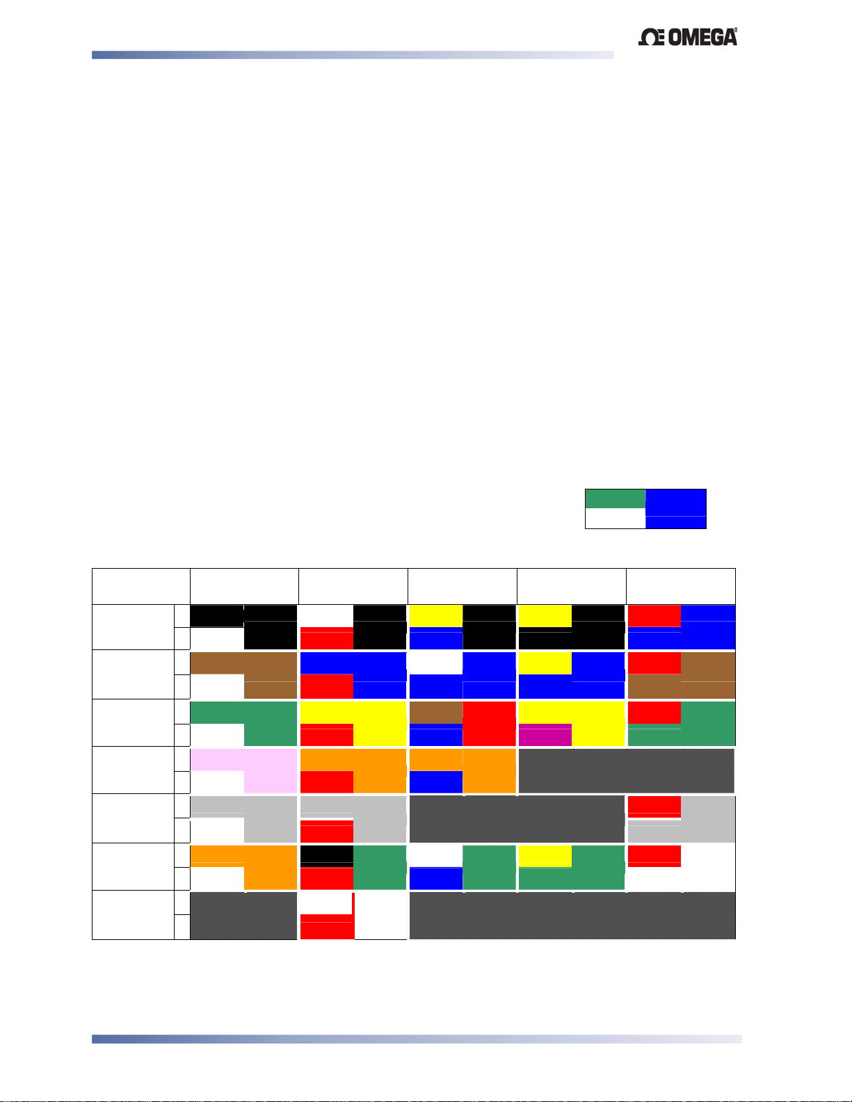
Thermocouple Wire Identification Chart
The different thermocouple types are identified by their wires’ color, and where possible, the
outer insulation as well. There are several standards in use throughout the world.
The table below shows the wire and sheath colors used for most
common thermocouple types. The format used in this table is:
+ Wire
- Wire
Sheath
Table 2. Thermocouple Extension Wire Colors
Type International
IEC584-3
Black
J
T
K
N
B
R & S
C (W5)
+*
White Red Blue Black Blue
-
Brown
+
White Red Blue Blue Brown
-
Green
+
White Red Blue Purple Green
-*
Pink
+
White Red Blue
-
Grey
+
White Red Grey
-
Orange
+
White Red Blue Green White
-
+
-
Black
Brown
Green
Pink
Grey
Orange
USA ANSI
MC 96.1
White
Black
Blue
Blue
Yellow
Yellow
Orange
Orange
Grey
Grey
Black
Green
White
White
Red
British
BS1843
Yellow
White
Brown
Orange
White
French
NFC 42-324
Black
Blue
Red
Orange
Green
Yellow
Black
Yellow
Blue
Yellow
Yellow
Yellow
Green
German
DIN 43710
Red
Blue
Red
Brown
Red
Green
Red
Grey
Red
White
Note:
* = Wire is magnetic
Connections Page 12
Page 21
Limit Devices–CN2516, CN2508 and CN2504 Product Manual
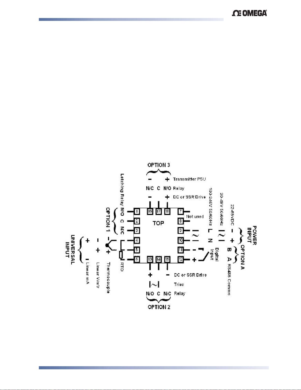
Connections and Wiring
The rear terminal connections for 1/
following diagrams.
DIN and 1/4 & 1/8 DIN instruments are illustrated in the
16
In general, all wiring connections are made to the instrument after it is installed. Copper wires
must be used for all connections (except thermocouple signal wires).
WARNING:
TO AVOID ELECTRICAL SHOCK, AC POWER WIRING MUST NOT BE CONNECTED TO THE
SOURCE DISTRIBUTION PANEL UNTIL ALL WIRING PROCEDURES ARE COMPLETED.
WARNING:
CHECK THE INFORMATION LABEL ON THE CASE TO DETERMINE THE CORRECT
VOLTAGE BEFORE CONNECTING TO A LIVE SUPPLY.
Note:
The wiring diagram below shows all possible combinations. The actual connections
required depend upon the features available on the model and the modules and options
fitted.
Figure 11. Rear terminals (1/16-DIN Instruments)
Connections Page 13
Page 22
Limit Devices–CN2516, CN2508 and CN2504 Product Manual
WARNING:
TO AVOID ELECTRICAL SHOCK, AC POWER WIRING MUST NOT BE CONNECTED TO THE
SOURCE DISTRIBUTION PANEL UNTIL ALL WIRING PROCEDURES ARE COMPLETED.
WARNING:
CHECK THE INFORMATION LABEL ON THE CASE TO DETERMINE THE CORRECT
VOLTAGE BEFORE CONNECTING TO A LIVE SUPPLY.
Note:
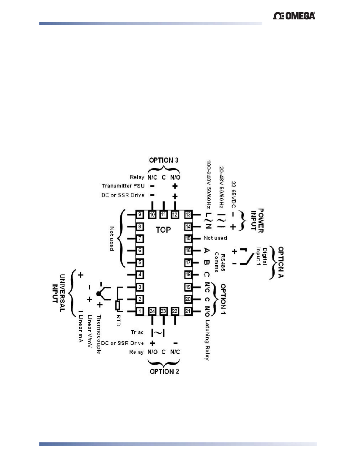
The wiring diagram below shows all possible combinations. The actual connections
required depend upon the features available on the model and the modules and options
fitted
Figure 12. Rear terminals (
Connections Page 14
1
/4-DIN & 1/8-DIN Instruments)
Page 23
Limit Devices–CN2516, CN2508 and CN2504 Product Manual
_
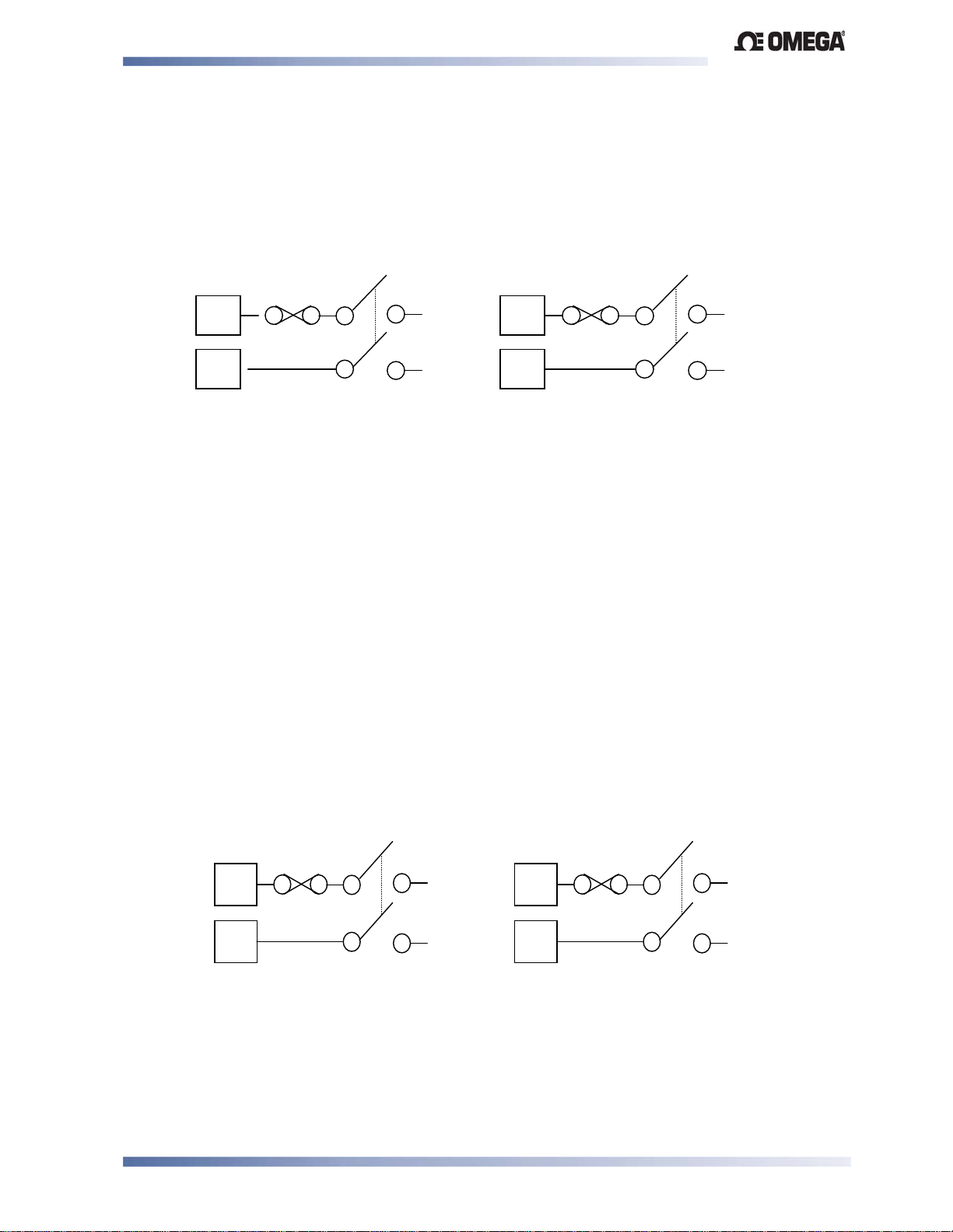
Power Connections - Mains Powered Instruments
Mains powered instruments operate from a 100 to 240V (±10%) 50/60Hz supply. Power
consumption is 7.5VA. Connect the line voltage (live and neutral) as illustrated via a two-pole
isolating switch (preferably located near the equipment) and a 1amp anti-surge fuse. If the
instrument has relay outputs with contacts carrying mains voltage, it is recommended that the
relay contacts supply should be switched and fused in a similar manner, but should be separate
from the instruments mains supply.
9
L
13
∼
10
WARNING:
CHECK THE INFORMATION LABEL ON THE CASE TO DETERMINE THE CORRECT
VOLTAGE BEFORE CONNECTING TO A LIVE SUPPLY.
CAUTION:
This equipment is designed for installation in an enclosure that provides adequate
protection against electric shock
1
/16 DIN
Figure 13. Mains Power Connections
N
14
1
/4 DIN & 1/8 DIN
L
∼
N
Power Connections - 24/48V AC/DC Powered Instruments
24/48V AD/DC powered instruments will operate from a 20 to 48V AC or 22 to 55V DC supply.
AC power consumption is 7.5VA max; DC power consumption is 5 watts max. Connection
should be via a two-pole isolating switch (preferably located near the equipment) and a 315mA
slow-blow (anti-surge type T) fuse.
9
_
13
∼
10
WARNING:
CHECK THE INFORMATION LABEL ON THE CASE TO DETERMINE THE CORRECT
VOLTAGE BEFORE CONNECTING TO A LIVE SUPPLY.
1
/16 DIN
Figure 14. 24/48V AC/DC Power Connections
Connections Page 15
+
14
1
/4 DIN & 1/8 DIN
∼
+
Page 24
Limit Devices–CN2516, CN2508 and CN2504 Product Manual
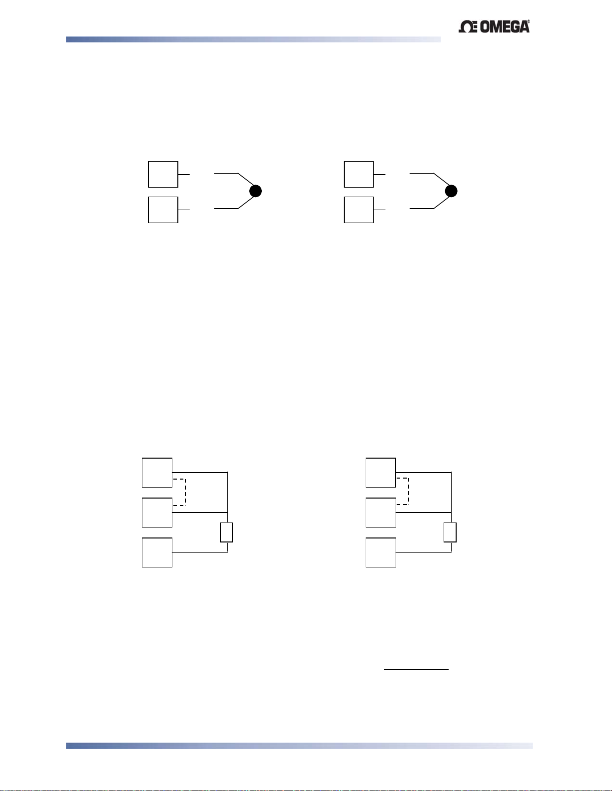
Universal Input Connections - Thermocouple (T/C)
Use only the correct thermocouple wire or compensating cable from the probe to the instrument
terminals avoiding joints in the cable if possible. Failure to use the correct wire type will lead to
inaccurate readings. Insure correct polarity of the wires by cross-referencing the colors with a
thermocouple reference table.
4
5
_
+
3
2
_
+
1
/16 DIN
1
/4 DIN & 1/8 DIN
Figure 15. Thermocouple Input Connections
Universal Input Connections – PT100 (RTD) input
For three wire RTDs, connect the resistive leg and the common legs of the RTD as illustrated.
For a two wire RTD a wire link should be used in place of the third wire (shown by dotted line).
Two wire RTDs should only be used when the leads are less than 3 metres long. Avoid cable
joints.
4
5
RTD RTD
6
3
2
1
1
/16 DIN 1/4 DIN & 1/8 DIN
Figure 16. RTD Input Connections
Four wire RTDs can be used, provided that the fourth wire is left unconnected. This wire should
be cut short or tied back so that it cannot contact any of the terminals on the rear of the
instrument.
Connections Page 16
Page 25
Limit Devices–CN2516, CN2508 and CN2504 Product Manual
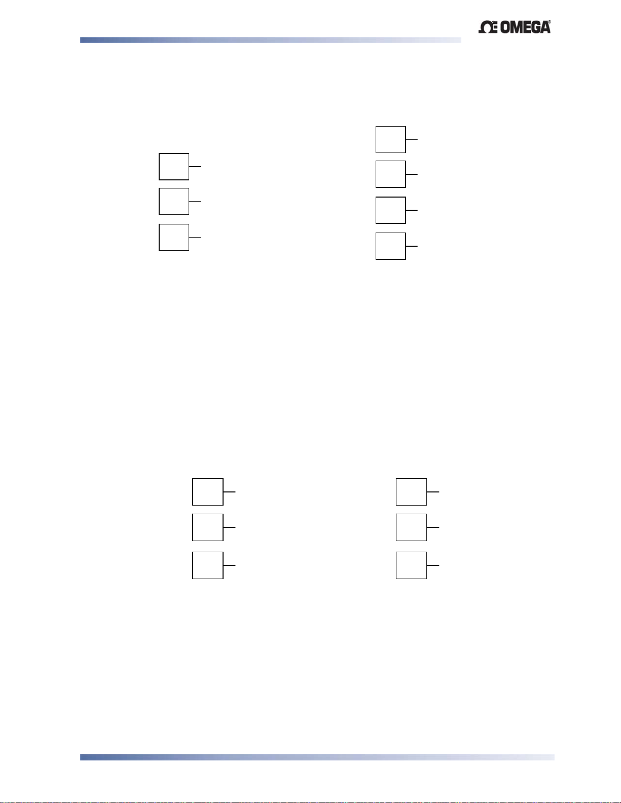
Universal Input Connections - Linear Volt, mV or mA input
Linear DC voltage, millivolt or milliamp input connections are made as illustrated. Carefully
4
5
6
_
+
mV/V
+
_-
mA
observe the polarity of the connections.
1
/16 DIN 1/4 DIN & 1/8 DIN
Figure 17. DC Volt, mV & mA Input Connections
Option Slot 1 – Relay Output Module
4
3
2
1
_
+
mV/V
+
_
mA
If option slot 1 is fitted with a fixed relay output, make connections as illustrated. The relay
contacts are rated at 5 amps resistive, 240 VAC.
19
20
21
1
/4 DIN & 1/8 DIN
N/C
COM
N/O
1
2
3
1
/16 DIN
N/O
COM
N/C
Figure 18. Option Slot 1 – Fixed Relay
Connections Page 17
Page 26
Limit Devices–CN2516, CN2508 and CN2504 Product Manual
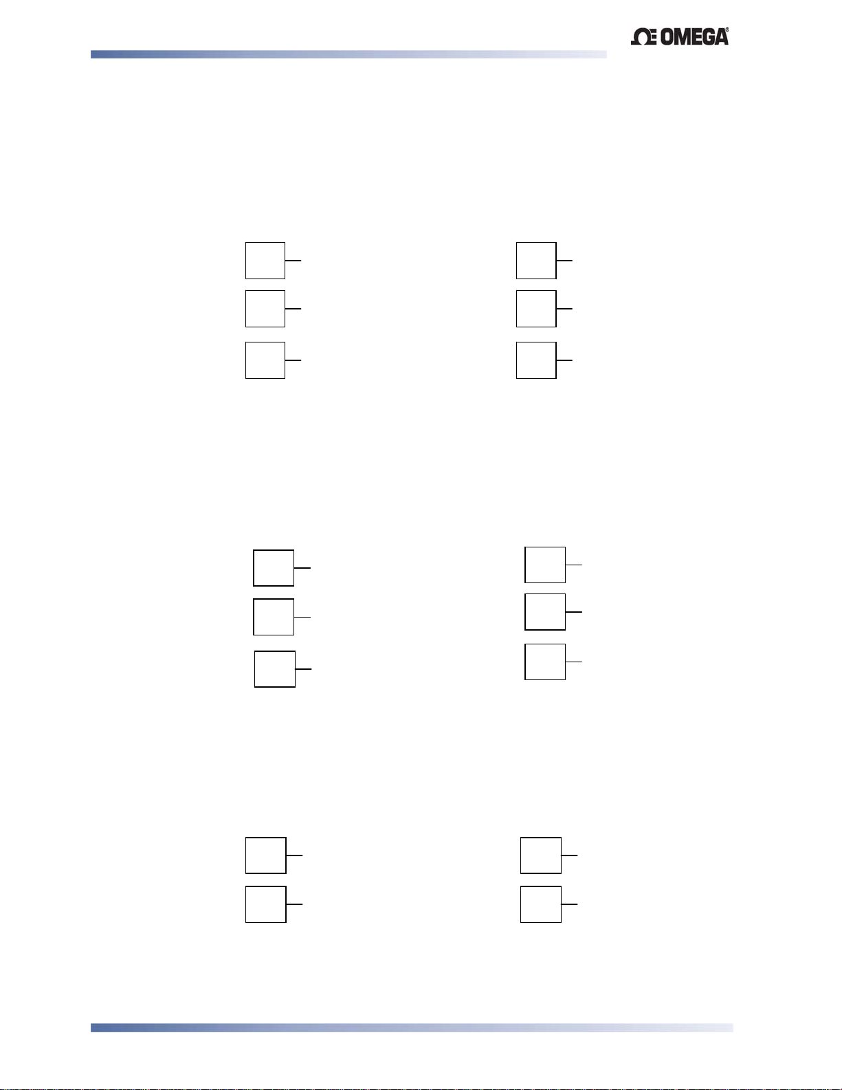
Option Slot 2 - Relay Output Module
If option slot 2 is fitted with a relay output module, make connections as illustrated. The relay
contacts are rated at 2 amps resistive, 240 VAC.
22
23
24
N/C
COM
N/O
13
14
15
1
/16 DIN 1/4 DIN & 1/8 DIN
N/O
COM
N/C
Figure 19. Option Slot 2 - Relay Module
Option Slot 2 - SSR Driver Output Module
If option slot 2 is fitted with an SSR driver output module, make connections as illustrated. The
solid-state relay driver is a 0-10V DC signal, load impedance must be no less than 500 ohms.
SSR driver outputs are not isolated from the signal input or other SSR driver outputs.
13
14
+
22
23
_
24
+
/4 DIN & 1/8 DIN
15
1
/16 DIN
_
1
Figure 20. Option Slot 2 - SSR Driver Module
Option Slot 2 - Triac Output Module
If option slot 2 is fitted with a Triac output module, make connections as shown. This output is
rated at 0.01 to 1 amp @ 280V AC 50/60Hz..
13
∼
14
1
/16 DIN
23
24
1
/4 DIN & 1/8 DIN
∼
Figure 21. Option Slot 2 - Triac Module
WARNING: THIS MODULE MUST NOT BE FITTED INTO OPTION SLOT 3.
Connections Page 18
Page 27
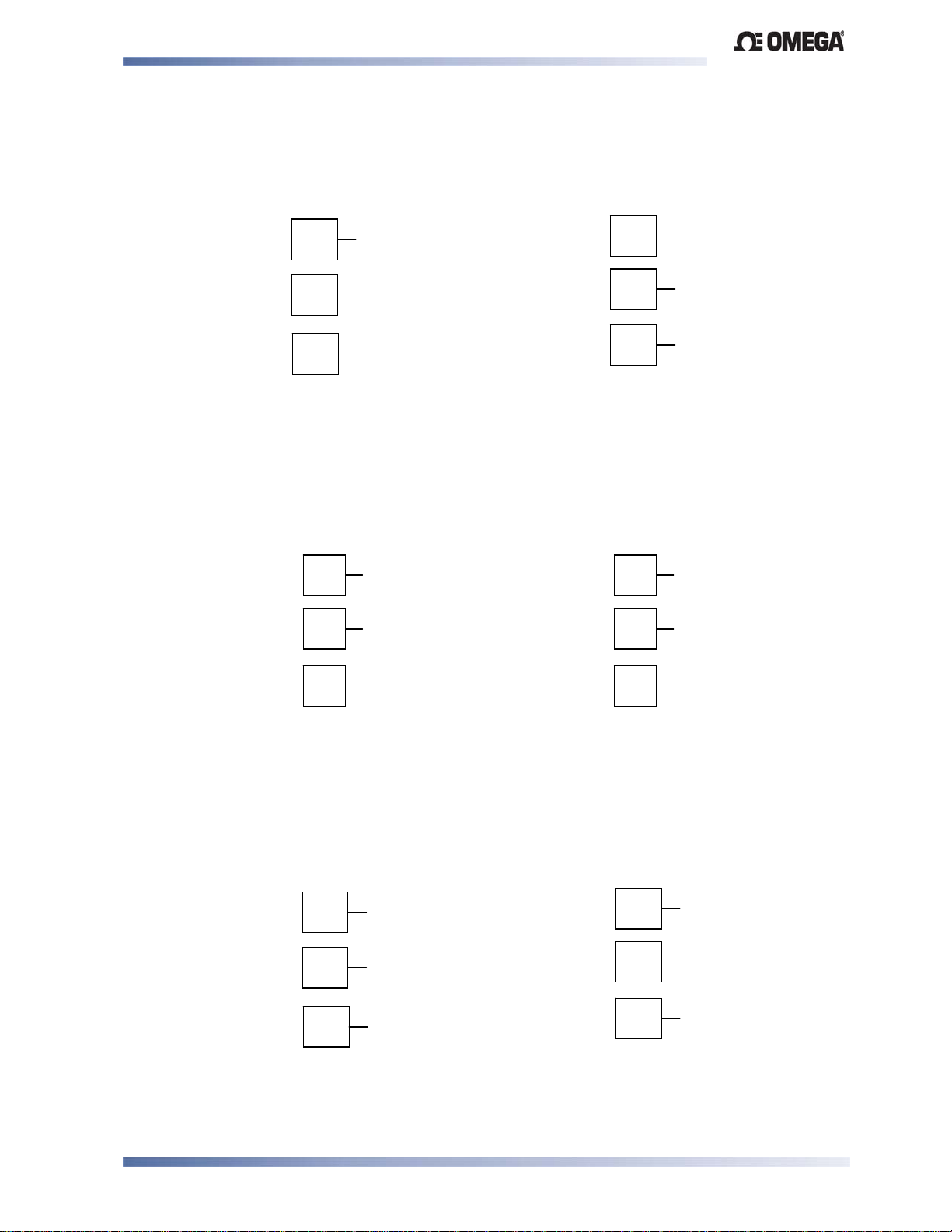
Limit Devices–CN2516, CN2508 and CN2504 Product Manual
Option Slot 2 - Linear Voltage or mADC Outp ut module
If option slot 2 is fitted with a DC linear output module, make connections as illustrated.
_
+
13
14
15
1
/16 DIN
+
22
23
_
1
24
/4 DIN & 1/8 DIN
Figure 22. Option Slot 2 - Linear Voltage & mADC module
Option Slot 3 - Relay Output Module
If option slot 3 is fitted with a relay output module, make connections as illustrated. The relay
contacts are rated at 2 amps resistive, 240 VAC.
16
17
N/C
COM
10
11
N/C
COM
12
N/O
18
1
/16 DIN 1/4 DIN & 1/8 DIN
N/O
Figure 23. Option Slot 3 - Relay Module
Option Slot 3 - SSR Driver Output Module
If option slot 3 is fitted with an SSR driver output module, make connections as illustrated. The
solid-state relay driver is a 0-10V DC signal; load impedance must be no less than 500 ohms.
SSR driver outputs are not isolated from the signal input or other SSR driver outputs.
16
17
18
1
/16 DIN
_
+
10
11
12
1
/4 DIN & 1/8 DIN
_
+
Figure 24. Option Slot 3 - SSR Driver Module
Connections Page 19
Page 28
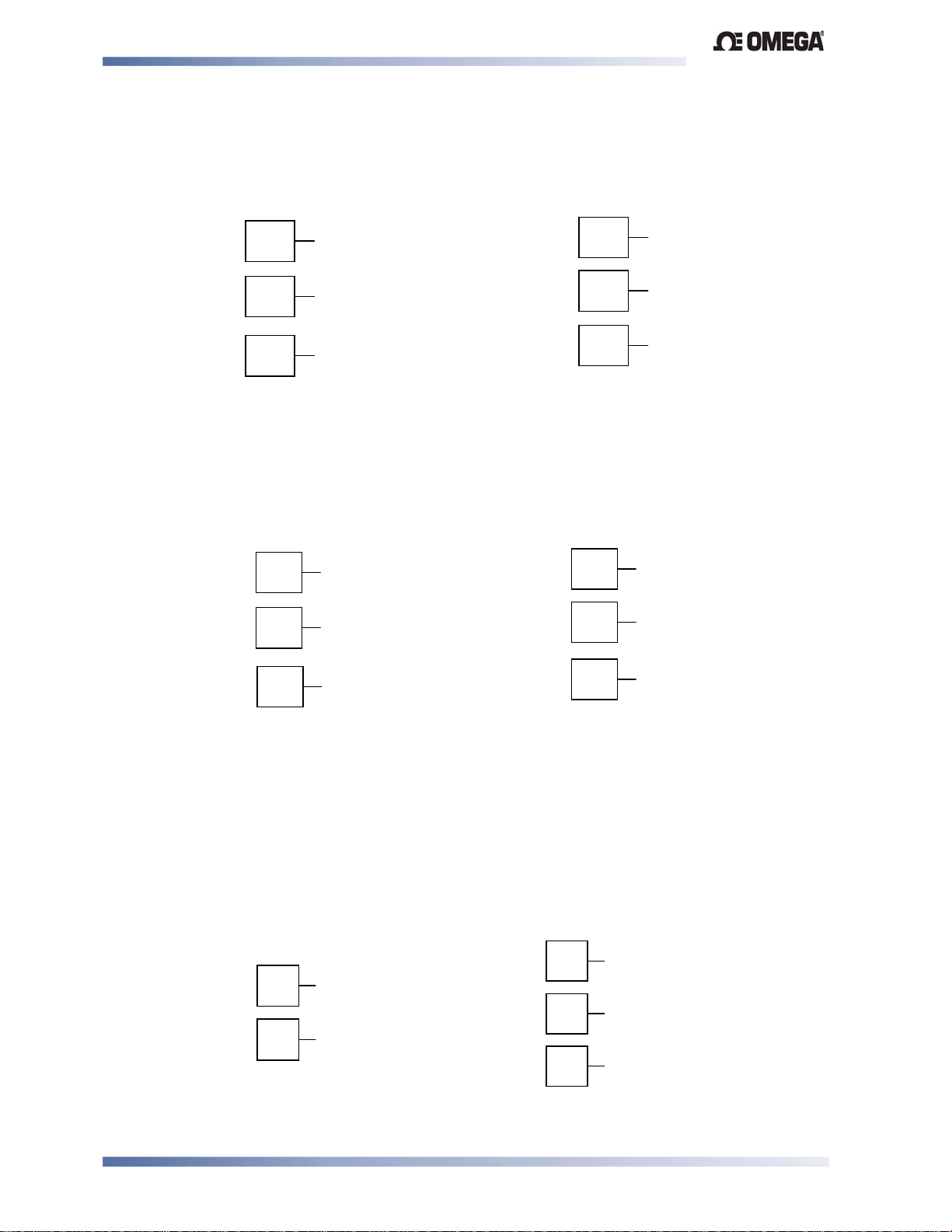
Limit Devices–CN2516, CN2508 and CN2504 Product Manual
A
Option Slot 3 - Linear Voltage or mADC Output module
If option slot 3 is fitted with a DC linear output module, make connections as illustrated.
_
+
16
17
18
1
/16 DIN
_
+
10
11
12
1
/4 DIN & 1/8 DIN
Figure 25. Option Slot 3 - Linear Voltage & mADC module
Option Slot 3 - Transmitter Power Supply Module
If option slot 3 is fitted with a transmitter power supply module, make connections as illustrated.
The output is an unregulated 24V DC, 22mA supply.
_
+
16
17
18
1
/16 DIN
_
+
10
11
12
1
/4 DIN & 1/8 DIN
Figure 26. Option Slot 3 - Transmitter Power Supply Module
WARNING:
THIS MODULE MUST NOT BE FITTED INTO OPTION SLOT 2.
Option Slot A Connections - RS485 Serial Communications Module
If option slot A is fitted with the RS485 serial communication module, connections are as
illustrated. Carefully observe the polarity of the A (Rx/Tx +ve) and B (Rx/Tx -ve) connections.
16
11
12
1
/16 DIN
B
A
RS485
1
/4 DIN & 1/8 DIN
17
18
B
COM
RS485
Figure 27. Option Slot A – RS485 Serial Communications Module
Connections Page 20
Page 29
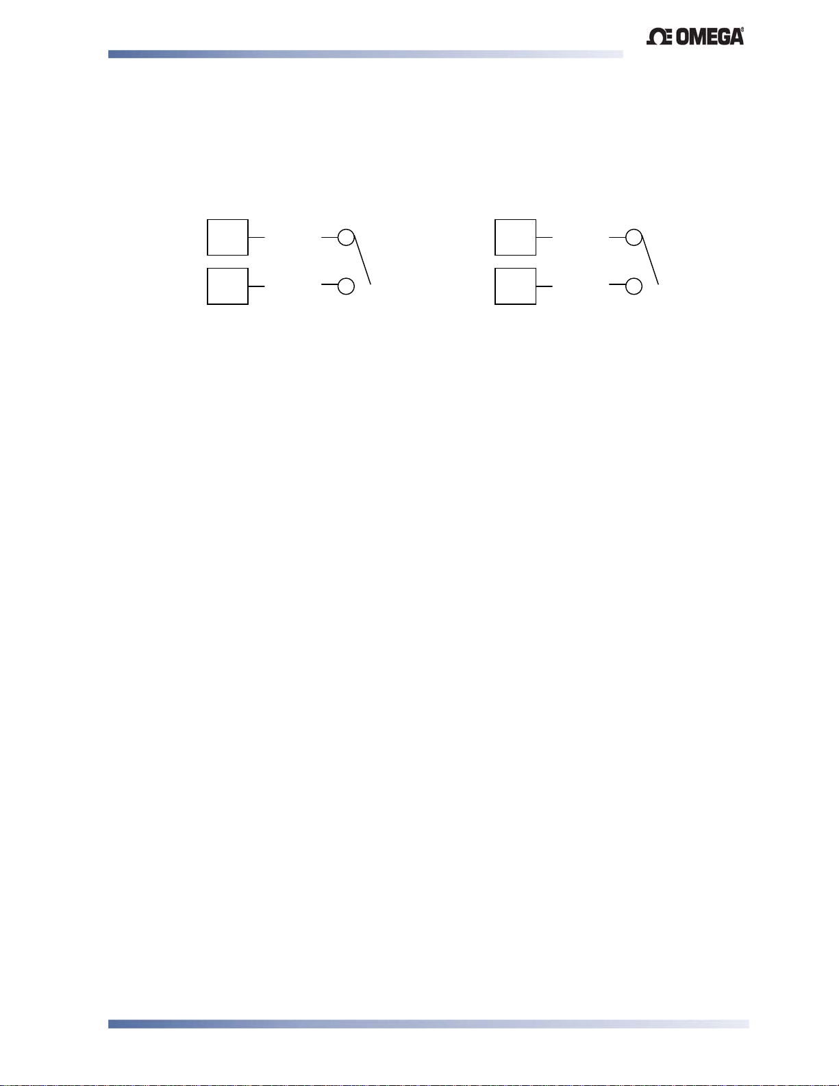
Limit Devices–CN2516, CN2508 and CN2504 Product Manual
Option Slot A Connections - Digital Input Module
If a digital input module is fitted in option slot A, this may be connected to either voltage free
contacts (e.g. switch or relay), or a TTL compatible voltage. Connections are shown below.
11
12
1
/16 DIN
_
+
Figure 28. Option Slot A – Digital Input Module
16
17
1
/4 DIN & 1/8 DIN
+
_
Connections Page 21
Page 30
Limit Devices–CN2516, CN2508 and CN2504 Product Manual
5 Powering Up
WARNING:
INSURE SAFE WIRING PRACTICES ARE FOLLOWED
The instrument must be powered from a supply according to the wiring label on the side of the
unit. The supply will be either 100 to 240V AC, or 24/48V AC/DC powered. Check the supply
voltage and connections carefully before applying power.
CAUTION:
When powering up for the first time, disconnect the output connections.
Powering Up Procedure
At power up, a self-test procedure is automatically started, during which all LED segments and
indicators are lit. At the first power up from new, or if the option modules are changed, #/
3C" will be displayed, indicating configuration is required (refer to section 6). At all other
times, the instrument returns to operator mode once the self-test procedure is complete.
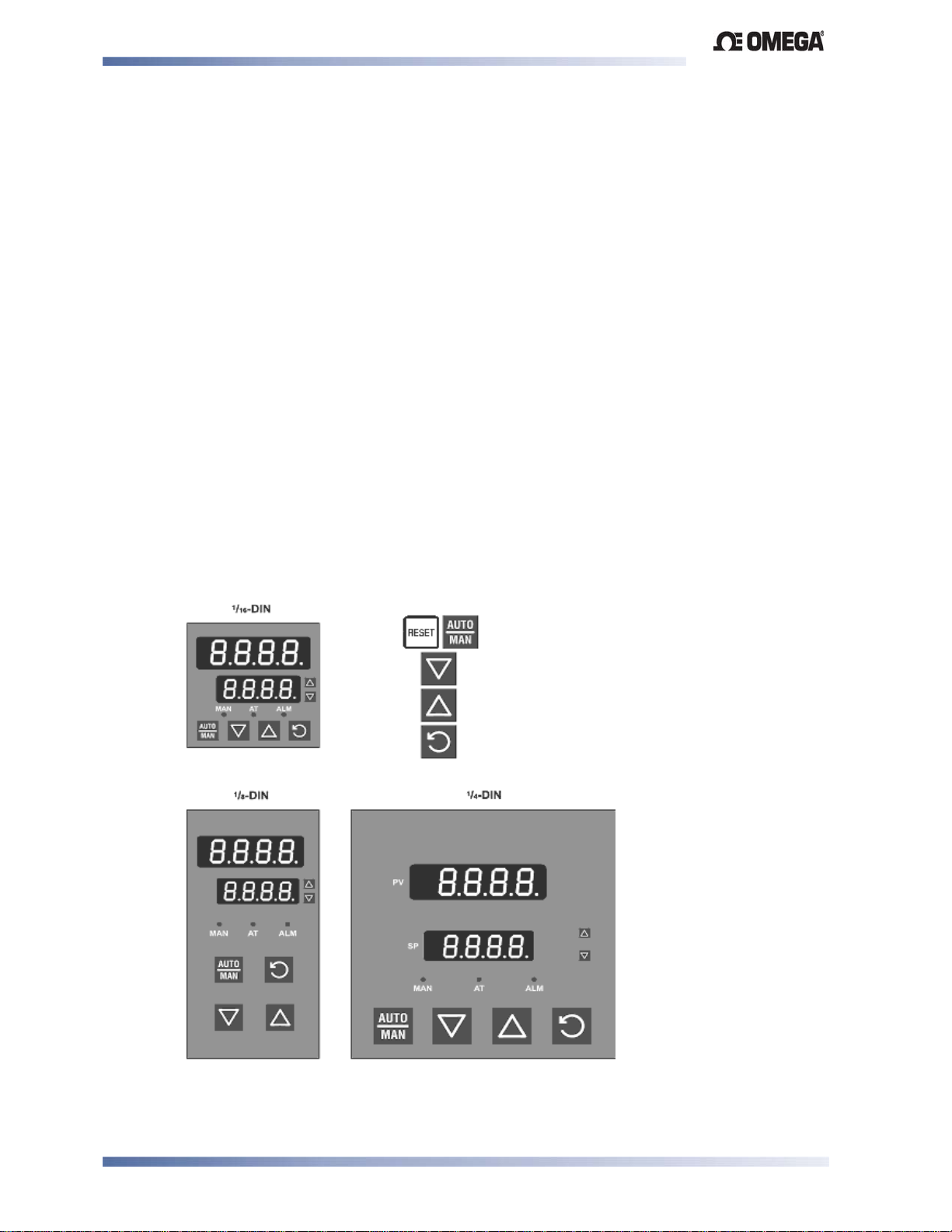
Overview of Front Panel
The illustration below shows a typical instrument front panel. Refer to the following table –
Typical LED functions for a description of the front panel indicators. Each model in the range
will vary slightly from the example shown.
Reset Key
Lower Key
Raise Key
Function Key
Figure 29. Typical front panel and keys
Powering Up Page 22
Page 31
Limit Devices–CN2516, CN2508 and CN2504 Product Manual
Displays
Controllers are provided with a dual line display and LED indicators for mode, automatic tune,
alarm, and output status. The upper display shows the process variable value during normal
operation, while the lower display shows the Setpoint value. See the preceding diagram Typical front panel and keys.
Keypad
Each instrument has either three or four switches, which are used to navigate through the user
menus and make adjustment to the parameter values. See - Overview of Front Panel above
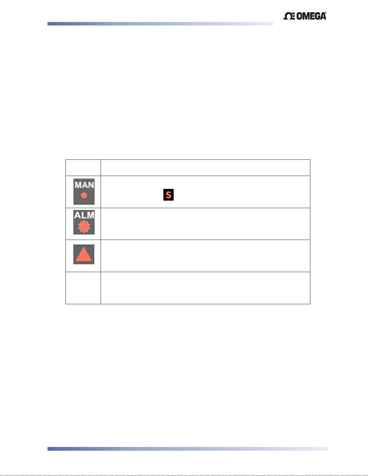
LED Functions
Table 3. Typical LED functions
LED
Function
ON indicates the Setup Mode has been entered
(This LED is labelled )
FLASHING indicates that an alarm condition is present
ON in unison with Primary output
Powering Up Page 23
Page 32
Limit Devices–CN2516, CN2508 and CN2504 Product Manual
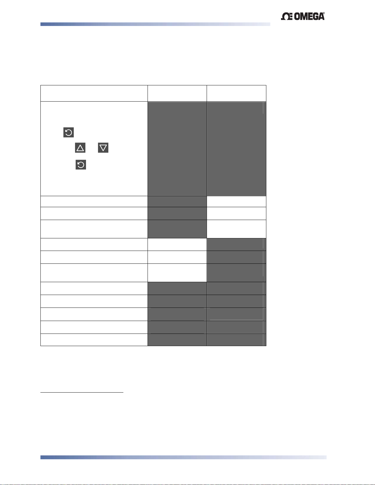
6 Messages and Error Indications
The following displays are shown when an error occurs or a hardware change is detected.
Table 4. Error/Faults conditions
Error/Faults Conditions Upper display Lower Display
(where fitted)
Configuration & Setup is required.
Seen at first turn on or if hardware
configuration changed.
Press to enter Configuration
Mode,
next press or to enter the
unlock code number,
then press to proceed.
Configuration must be completed
before return to operator mode is
1
allowed
#/
(#/ for 1
second)
3C"
Input more than 5% over-range2
Input more than 5% under-range3
Sensor Break. Break detected in
2$$9 *
2''9 *
) ( *
Normal Display
Normal Display
Normal Display
the input sensor or wiring
Auxiliary input over-range
Auxiliary input under-range
Auxiliary Break. Break detected in
Normal Display
Normal Display
Normal Display
2$$9 *
2''9 *
) ( *
the auxiliary input
Option 1 module fault.
Option 2 module fault.
Option 3 module fault.
Option A module fault.
Option B module fault.
****
****
****
****
@C
@C
@C
@C
** @C
* Note
Input sensor and Auxiliary over/under-range or break indications will be seen wherever
these values would normally be displayed.
1
This feature does not guarantee correct configuration. It only helps to insure that the unit will be configured
before use. Use of set-up mode is not enforced but may be essential for the user’s application.
2
If the PV display exceeds
3
Indicators will allow up to 10% under-range on non-zero based Linear ranges. If the PV display is less than
before the % under-range is reached, an under-range indication is given.
before 5% over-range is reached, an over-range indication is given.
Instrument Operation Modes Page 24
Page 33
Limit Devices–CN2516, CN2508 and CN2504 Product Manual
7 Instrument Operation Modes
All instruments in the range share a similar user interface. For more details, refer to the mode
tables below.
Select Mode
This mode is used to gain entry to each of the modes available in the instrument.
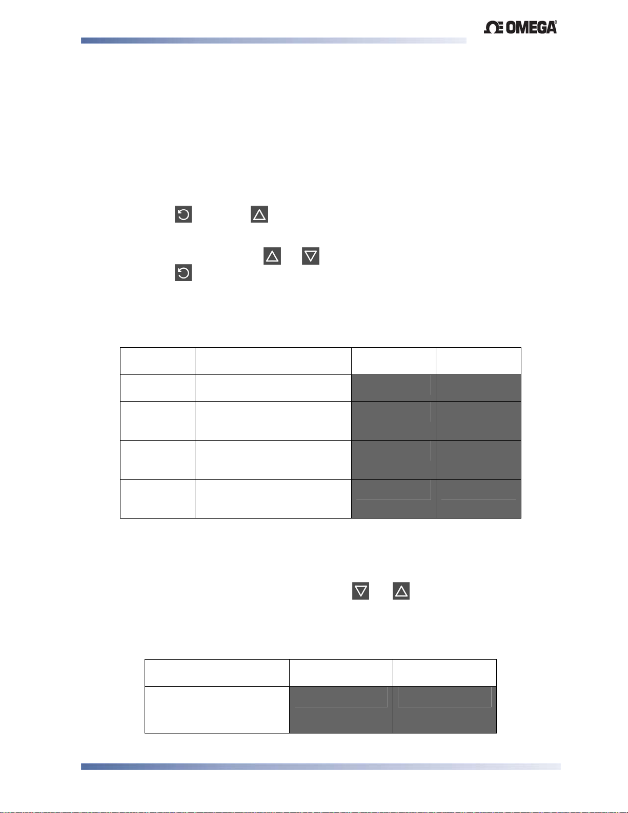
Entry into the Select Mode
Hold down and press in any mode to force the unit to enter Select Mode.
Navigating in Select Mode
Once in Select Mode, press or to select the required mode,
then press to enter the chosen mode.
To prevent unauthorized entry to Configuration, Setup and Automatic Tuning modes, an unlock
code is required. These are shown in the - Lock code values table.
Table 5. Select Mode Menus
Mode Description Upper/Main
Display
Operator
Mode
Set Up Mode Used to tailor the instrument to
Configuration
Mode
Product
Information
Mode
The Default Mode on power up
used for normal operation.
the application, adjustment of
tuning terms etc.
Used to configure the
instrument for first time use or
on re-installation.
Used to check the hardware,
firmware and manufacturing
information of the instrument.
@/+ -'3/
-!/@ -'3/
3C" -'3/
C" -'3/
Lower
Display
Unlock Codes
The 0'N screen is seen before entry is allowed to Configuration, Setup and Automatic Tuning
modes.
An unlock code must be correctly selected using the or keys to enter the required
mode. An incorrect entry results in a return to Select Mode. The value of the lock codes only
can be changed from within the modes to which they apply.
Table 6. Lock Code – Entry and Default Values
Description Upper/Main
Lower Display
Display
Default values are:
0'N
Set-up mode =
Configuration Mode = .
Instrument Operation Modes Page 25
Page 34
Limit Devices–CN2516, CN2508 and CN2504 Product Manual
Product Information Mode
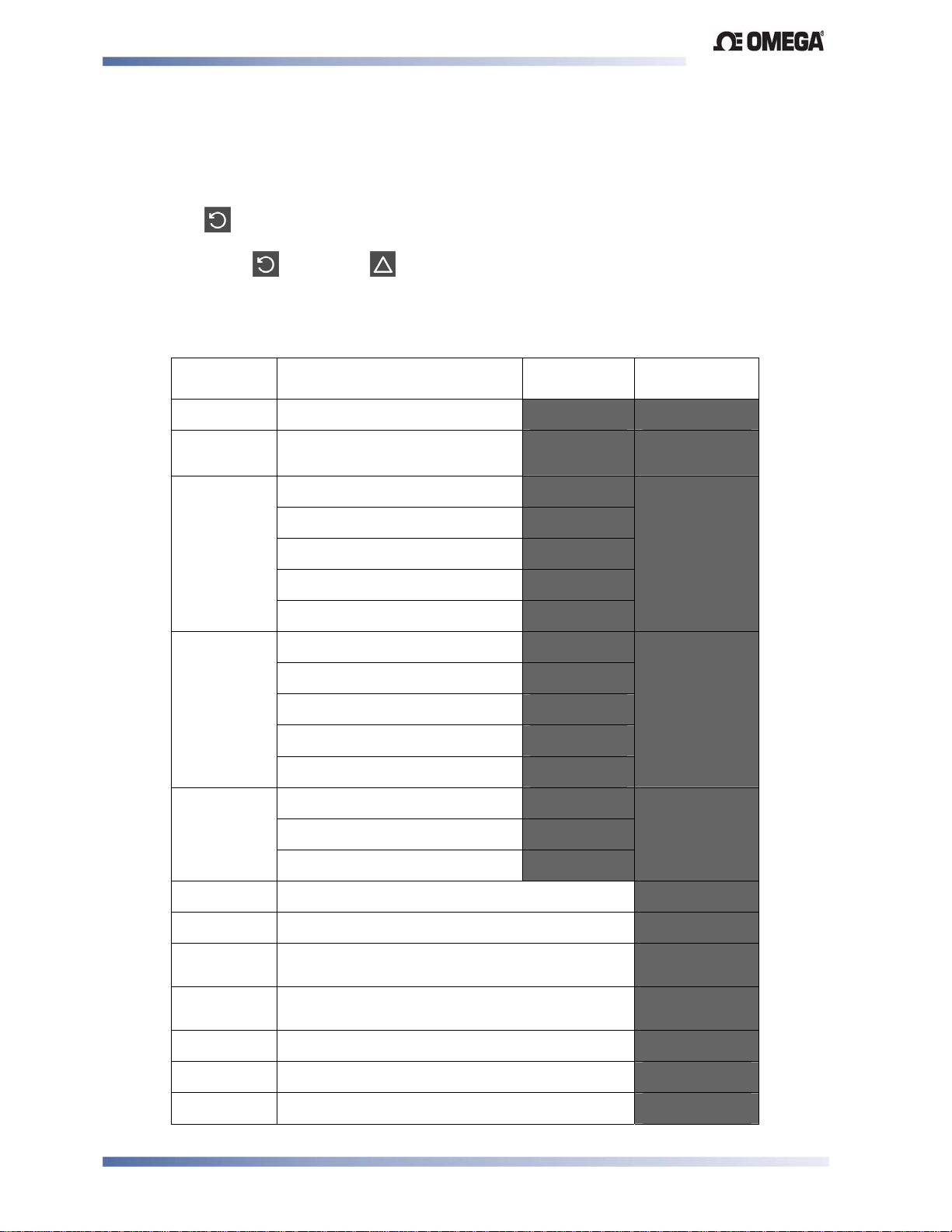
This is a read only mode describing the instrument and the options fitted to it.
Navigating in the Product Information Mode
Press to view each parameter in turn.
Hold Down and press to return to Select Mode.
Note: If there is no key activity for 2 minutes the device automatically returns to operator
mode
Table 7. Product Information Mode Parameters
Parameter Possible Values Upper/Main
Display
Input type Universal input
Option 1
module type
Option 2
module type
Option 3
module type
Auxiliary
option A
module type
Firmware
Issue No.
Product Rev
Level
Date of
manufacture
Serial No.1
Serial No.2
Serial No. 3
Relay
No option fitted.
Relay
SSR drive
Triac
Linear voltage / current output
No option fitted.
Relay
SSR drive
Linear voltage / current output
24V Transmitter power supply
No option fitted
RS485 comms
Digital input
Value displayed is firmware type number
Value displayed is firmware issue number
Value displayed is Product Revision Level.
Manufacturing date code (mmyy)
First four digits of serial number
Second four digits of serial number
Last four digits of serial number
0C %C:
+'5 )C
CC )C
+'5
--+
/+
'C
CC )C
=+'5
--+
'C
=N
CC! )C
+
=#
Lower
Display
"<&
%,,
)*'
=Mm
-C
-C
-C
Instrument Operation Modes Page 26
Page 35
Limit Devices–CN2516, CN2508 and CN2504 Product Manual
Lock Code View
In the event that a lock code is forgotten, the instrument lock code values can be seen in the
lock code view. In this view the codes are read only, the codes can be changed from the mode
to which they apply.
Entry and Navigating in Lock Code View Mode
Press and together while the instrument is powering up until the 3'N display
is shown.
Once in this mode
Press
to step between lock codes.
Note:
If there is no key activity for 2 minutes the instrument returns to Operator Mode. To forcibly
exit this view, switch off the instrument.
Table 8. Lock Code View Menu
Lock Code
Name
Configuration
Lock Code
Setup Lock
Code
Description Upper/Main
Lower Display
Display
Read only view of
Configuration Lock Code.
Read only view of Setup
Mode Lock Code.
Current Value
Current Value
3'N
-'N
Instrument Operation Modes Page 27
Page 36

Limit Devices–CN2516, CN2508 and CN2504 Product Manual
8 CN2516, CN2508 & CN2504 – Model Group
Limit Controllers protect processes that could be damaged or become hazardous under fault
conditions. They shut down the process at a preset level. Three model sizes are available:
CN2516
CN2504
High or low trip 5 amp latching limit relay
Exceed & relay trip indicators 2 Annunciators or process alarms
RS485 Modbus and ASCII comms option Remote reset option
PV retransmit option PC configuration option
CN2516, CN2508 & CN2504 Limit Devices - Configuration Mode
This mode is normally used only when the instrument is configured for the first time or when a
major change is made to the controller characteristics. The Configuration Mode parameters
must be set as required before adjusting parameters in Setup Mode, or attempting to use the
instrument in an application.
1
/16 DIN Limit Device (48 x 48mm), CN2508 1/8 DIN Limit Device (96 x 48mm) and
1
/4 DIN Limit Device (96 x 96mm).
Entry into the Configuration Mode
CAUTION:
Adjustments to these parameters should only be performed by personnel
competent and authorized to do so.
Configuration is entered from Select Mode
Hold down and press to force the controller into the Select Mode.
then
Press or to navigate to the Configuration Mode option, then press .
Note:
Entry into this mode is security-protected by the Configuration Mode Lock Code. Refer to
the Unlock Code section for more details.
Scrolling through Parameters and Values
Press to scroll through the parameters (parameters are described below).
Note:
Only parameters that are applicable to the hardware options chosen will be displayed.
Changing Parameter Values
Press to navigate to the required parameter, then press or to set the value
as required.
CN2516, CN2508 & CN2504 – Model Group Page 28
Page 37
Limit Devices–CN2516, CN2508 and CN2504 Product Manual
When a value is changed, the display will flash to indicate that confirmation of the change is
required. The value will revert back if not confirmed within 10 seconds.
Press to accept the change.
Or
Press to reject the change and to move onto the next parameter.
Hold down and press to return to Select Mode.
Note:
If there is no key activity for 2 minutes, the instrument returns to the operator mode.
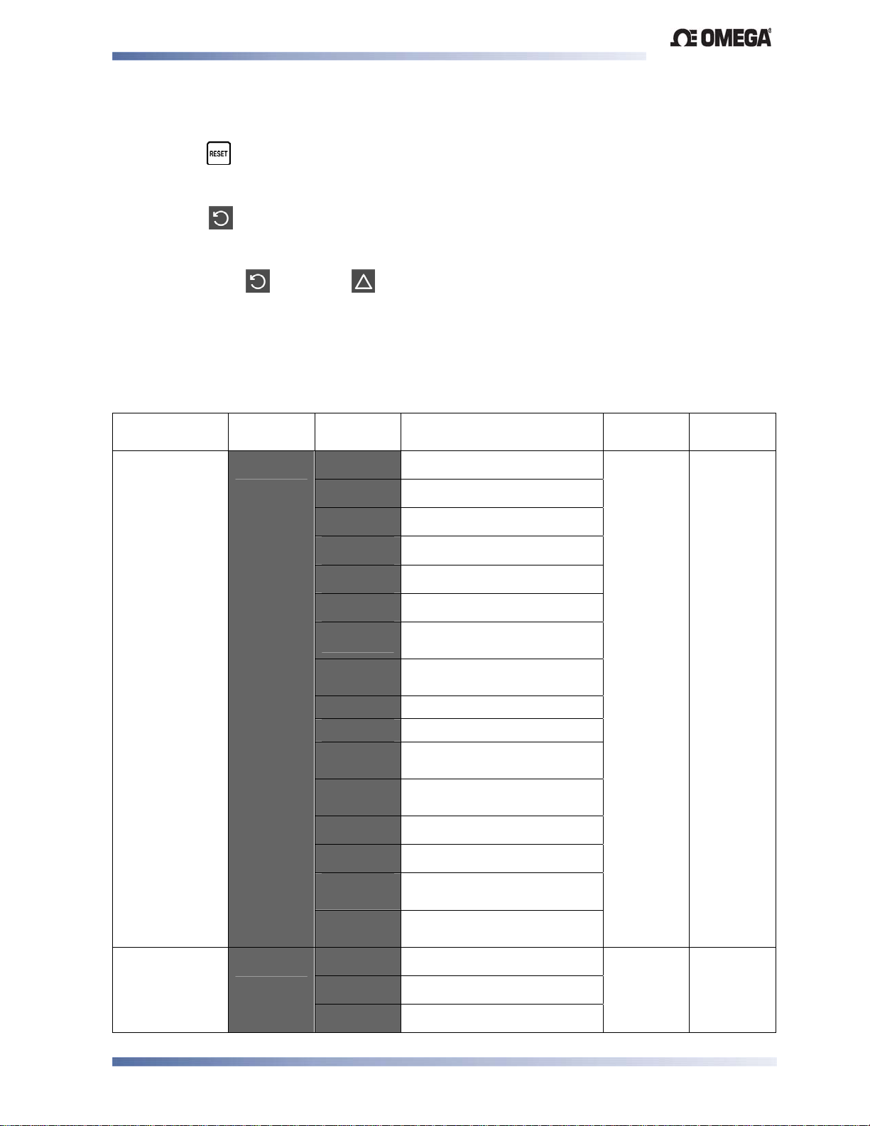
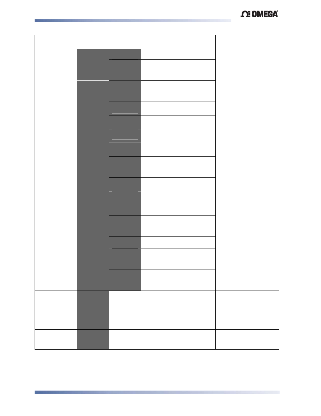
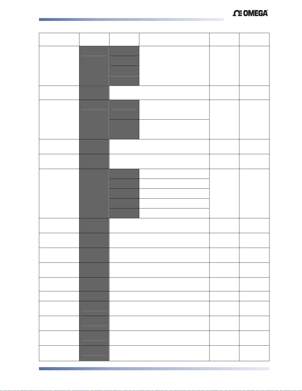
Table 9. CN2516, CN2508 & CN2504 Configuration Mode
Parameters
Parameter Lower
Display
Input type and
Range
%C)/ 3
Upper
Display
"
33
3"
&3
&"
6. 3
6. "
K3
K"
k. 3
K. "
'3
'"
'. 3
'. "
(3
("
+3
Description Default
Value
B type: 100 to 1824 ºC
B type: 211 to 3315 ºF
C type: 0 to 2320 ºC
C type: 32 to 4208 ºF
63
for Europe
6"
for USA
When
Visible
Always
J type: -200 to 1200 ºC
J type: -328 to 2192 ºF
J type: -128.8 to 537.7 ºC
with decimal point
J type: -199.9 to 999.9 ºF
with decimal point
K type: -240 to 1373 ºC
K type: -400 to 2503 ºF
K type: -128.8 to 537.7 ºC
with decimal point
K type: -199.9 to 999.9 ºF
with decimal point
L type: 0 to 762 ºC
L type: 32 to 1403 ºF
L type: 0.0 to 537.7 ºC
with decimal point
L type: 32.0 to 999.9 ºF
with decimal point
N type: 0 to 1399 ºC
N type: 32 to 2551 ºF
R type: 0 to 1759 ºC
63
for Europe
6"
Always
CN2516, CN2508 & CN2504 – Model Group Page 29
Page 38
Limit Devices–CN2516, CN2508 and CN2504 Product Manual
Parameter Lower
Display
Input type and
Range
(Continued)
Scale Range
Upper Limit
Scale Range
Lower Limit
+1'
+''
Upper
Description Default
Display
+"
-3
-"
/3
/"
/. 3
/. "
)3
)"
).3
)/"
)/. 3
)/. "
:
:
:
R type: 32 to 3198 ºF
S type: 0 to 1762 ºC
S type: 32 to 3204 ºF
T type: -240 to 400 ºC
T type: -400 to 752 ºF
T type: -128.8 to 400.0 ºC
with decimal point
T type: -199.9 to 752.0 ºF
with decimal point
PtRh20% vs PtRh40%:
0 to 1850 ºC
PtRh20% vs PtRh40%:
32 to 3362 ºF
Pt100: -199 to 800 ºC
Pt100: -328 to 1472 ºF
Pt100: -128.8 to 537.7 ºC
with decimal point
Pt100: -199.9 to 999.9 ºF
with decimal point
0 to 20mA DC
4 to 20mA DC
0 to 50mV DC
10 to 50mV DC
.
:
:
:
:
Scale Range Lower Limit +100 to Range
Max
Range Min. to Scale range Upper Limit 100
0 to 5V DC
1 to 5V DC
0 to 10V DC
2 to 10V DC
Value
for USA
Linear
inputs =
1000
(°C/°F =
max
range)
Linear = 0
(°C/°F =
min range)
When
Visible
Always
Always
CN2516, CN2508 & CN2504 – Model Group Page 30
Page 39
Limit Devices–CN2516, CN2508 and CN2504 Product Manual
Parameter Lower
Display
Decimal point
position
Process
Variable Offset
Limit Action
Setpoint Upper
Limit
Setpoint Lower
Limit
Alarm 1Type
Process High
Alarm 1 value*
Process Low
Alarm 1 value*
Deviation
Alarm 1 Value*
Band Alarm 1
value*
Alarm 1
Hysteresis*
Alarm 2 Type
Process High
Alarm 2 value*
Process Low
Alarm 2 value*
Deviation
Alarm 2 Value*
Band Alarm 2
value*
=)-
""-
3.*' $
-)1'
-)''
' ):$
)?
)'
='
'
$4
'
)?
)'
='
'
Upper
Description Default
Display
Decimal point position in
non-temperature ranges.
±Span of controller (see CAUTION note
at end of section)
'
Current Setpoint value to Scale Range
Maximum
Scale Range Minimum to current Setpoint
value
):'
=
C=
CC
Range Min. to Range Max.
Range Min. to Range Max
±span from setpoint
1 LSD to full span from setpoint.
1 LSD to 100% of span (in display units)
on “safe” side of alarm point.
As for alarm 1 type
Range Min. to Range Max.
Range Min. to Range Max.
±span from setpoint.
1 LSD to full span from setpoint.
0 = XXXX
1 = XXX.X
2 = XX.XX
3 = X.XXX
High Limit. Limit relay is
energized when process
“safe” (PV < Limit Setpoint)
Low Limit. Limit relay is
energized when process
“safe” (PV > Limit Setpoint)
Process High Alarm
Process Low Alarm
Deviation Alarm
Band Alarm
No alarm
Value
$
Range
Max.
Range
Min
):$
Range
Max.
Range
Min.
):'
Range
Max.
Range
Min.
When
Visible
%C@.
=
mV, V or
mA
Always
Always
Always
Always
Always
'=
):$
'=
):'
'=
=
'=
C=
Always
Always
'=
):$
'=
):'
'=
=
=
'
C=
CN2516, CN2508 & CN2504 – Model Group Page 31
Page 40
Limit Devices–CN2516, CN2508 and CN2504 Product Manual
Parameter Lower
Display
Alarm 2
Hysteresis*
Output 2
Usage
Linear Output
2 Range
Retransmit
Output 2 Scale
maximum
Retransmit
Output 2 Scale
minimum
Output 3
Usage
$4
0-
/4) :
+$
+'
0-
Upper
Description Default
Display
1 LSD to 100% of span (in display units)
on “safe” side of alarm point.
'Mm/
7:=
:+
:=
:+
+:=
+:+
+:=
+:+
C:=
C:+
+!/-
+!/)
:
:
:
:
Display value where output is maximum
Limit Output Relay
Alarm 1, Direct Acting
Alarm 1, Reverse Acting
Alarm 2, Direct Acting
Alarm 2, Reverse Acting
Logical Alarm 1 OR Alarm 2
Direct Acting
Logical Alarm 1 OR Alarm 2
Reverse Acting
Logical Alarm 1 AND Alarm
2, Direct Acting
Logical Alarm 1 AND Alarm
2, Reverse Acting
Limit Annunciator, Direct
Acting
Limit Annunciator, Reverse
Acting
Retransmit SP Output
Retransmit PV Output
0 to 5 V DC output 1
0 to 10 V DC output
2 to 10 V DC output
0 to 20 mA DC output
4 to 20 mA DC output
to
to
Display value where output is minimum
As for output 2
Value
:=
when
@C is
not linear
output
type,
+ /) if
@C is
linear
output
type
:
Range
max
Range min
7:=
When
Visible
Always
@C
= +'5
Not linear
Not linear
Not linear
Not linear
Not linear
Not linear
Not linear
Not linear
Not linear
Not linear
Linear only
Linear only
@C=
'C
0,!=
+!/- or
+!/)
0,!=
+!/- or
+!/)
@C
not
is
CC!
Linear Output
3 Range
/4)
As for output 2
:
@C
'C
CN2516, CN2508 & CN2504 – Model Group Page 32
=
Page 41
Limit Devices–CN2516, CN2508 and CN2504 Product Manual
Parameter Lower
Display
Retransmit
Output 3 Scale
maximum
Retransmit
Output 3 Scale
minimum
Display
Strategy
Comms
Protocol
Bit rate
Communications Address
Communications Write
Enable
Configuration
Mode Lock
Code
+$
+'
=,@ C
)+/ -3%
1=
==+
3 C
3'N
Upper
Description Default
Display
Display value where output is maximum
to
to
Display value where output is minimum
PV is visible in Operator
mode
=-
-"
MmC
Mm
Mm
.
.
.
.
.
r_o
r_Ww
to
PV not visible in Operator
mode
Displays -" in Operator
mode when Limit Output is
not active
ASCII
Modbus with no parity
Modbus with Even Parity
Modbus with Odd Parity
1.2 kbps
2.4 kbps
4.8 kbps
9.6 kbps
19.2 kbps
A unique address for each
instrument between 1 to 255
(Modbus), or 1 to 99 (Ascii)
Read only. Comms
writes ignored
Read / Write. Writing via
Comms is possible
Value
Range
max
Range min
C
MmC
.
r_ Ww
When
Visible
0,!=
+!/- or
+!/)
0,!=
+!/- or
+!/)
Always
@C=
+
@C
+
@C
+
Always
Always
Notes:
Option Slot 1 is a fixed Limit Relay output. A Digital Input module, if fitted to Option Slot A
will duplicate the function of the front Reset key . As these functions cannot be
changed, configuration menus are not required.
Alarm parameters marked * are repeated in Setup Mode.
=
=
CAUTION:
Process Variable Offset modifies the measured value to compensate for probe
errors. Positive values increase the reading, negative values are subtracted. This
parameter is, effectively, a calibration adjustment and MUST be used with care.
CN2516, CN2508 & CN2504 – Model Group Page 33
Page 42
Limit Devices–CN2516, CN2508 and CN2504 Product Manual
CN2516, CN2508 & CN2504 Limit Devices – Setup Mode
This mode is normally selected only after Configuration Mode has been completed, and is used
when a change to the process set up is required.
Note:
Entry into Setup Mode is security-protected by the Setup Mode lock code.
Entry into the Setup Mode
Hold down and press to enter the Select Mode
Press or to navigate to the Setup Mode option, then press to enter Setup
Mode.
The Setup LED will light while in Setup mode
Scrolling through Parameters & Values
Press to scroll through the parameters (refer to the table below) and their values.
Changing Parameter Values
Press to select the required parameter, then press or to set the value as
required.
Once the displayed value is changed, the effect is immediate. No confirmation of the
change is required.
Note:
If there is no key activity for two minutes, the instrument returns to the operator mode.
Table 10. CN2516, CN2508 & CN2504 Set Up Mode Parameters
Parameter Lower
Display
Limit Setpoint value
-)
Upper Display
Adjustment Range
Scaled Range Minimum to
Scaled Range Maximum
Default
Value
Range
max when
When
Visible
Always
3/+'=$
Range min
when
3/+'='
Limit Hysteresis
Input Filter Time
constant
$5-/
"'/
1 LSD to full span in
display units, on the safe
side of the limit SP
OFF, 0.5 to 100.0 secs in
0.5 sec increments
(see CAUTION note at
end of section)
.
Always
Always
CN2516, CN2508 & CN2504 – Model Group Page 34
Page 43
Limit Devices–CN2516, CN2508 and CN2504 Product Manual
Parameter Lower
Display
Process High Alarm 1
value*
Process Low Alarm 1
value*
Deviation Alarm 1
Value*
Band Alarm 1 value*
Alarm 1 Hysteresis*
Process High Alarm 2
value*
Process Low Alarm 2
value*
Deviation Alarm 2
Value
Band Alarm 2 value*
Alarm 2 Hysteresis*
Set-up Lock Code
**First Operator mode displays follows.
)?
)'
='
'
$4
)?
)'
='
'
$4
-'N
Upper Display
Adjustment Range
Range Min. to Range
Max.
Range Min. to Range
Max.
±span from setpoint
1 LSD to full span from
setpoint.
Up to 100% of span
Range Min. to Range
Max.
Range Min. to Range
Max.
±span from setpoint
1 LSD to full span from
setpoint.
Up to 100% of span
0 to 9999
Default
Value
Range
Max.
Range
Min.
Range
Max.
Range
Min.
When
Visible
' = ):$
' = ):'
'
'
Always
' = ):$
' = ):'
'
'
Always
Always
Note:
Alarm parameters marked * are repeated in Configuration Mode.
Note:
**Once the complete list of Set Up Mode parameters has been displayed, the first
Operator Mode display is shown without exiting from Set Up Mode.
= =
= C=
= =
= C=
CAUTION:
An excessively large filter time could significantly delay detection of a limit
condition. Set this value to the minimum required to remove noise from the process
variable.
CN2516, CN2508 & CN2504 – Model Group Page 35
Page 44
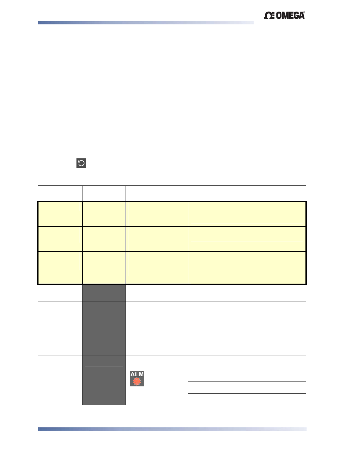
Limit Devices–CN2516, CN2508 and CN2504 Product Manual
CN2516, CN2508 & CN2504 Limit Devices - Operator Mode
This is the mode used during normal operation of the instrument. It can be accessed from
Select Mode, and is the usual mode entered at power-up.
WARNING:
IN NORMAL OPERATION, THE OPERATOR MUST NOT REMOVE THE INSTRUMENT FROM
ITS HOUSING OR HAVE UNRESTRICTED ACCESS TO THE REAR TERMINALS, AS THIS
WOULD PROVIDE POTENTIAL CONTACT WITH HAZARDOUS LIVE PA RTS.
CAUTION:
Set all Configuration Mode parameters and Setup Mode parameters as required
before starting normal operations.
Navigating in Operator Mode
Press to move between displays.
Table 11. CN2516, CN2508 & CN2504 Operator Mode Displays
Upper
Display
PV Value
Limit SP
Value
-" or
+- /
High Limit
Hold
Low Limit
Hold
Exceed Time
Value
Active Alarm
Status
Lower
Display
Limit SP
Value
Blank
Blank or
PV Value
$$=
'$=
/
'-/
When Visible Description
Display strategy is
set to C.
(Initial Screen)
Display strategy is
set to =-.
(Initial Screen)
Display strategy is
set to -" .
(Initial Screen)
3/+'
= $ in
Configuration Mode
= ' in
3/+'
Configuration Mode
Always available Accumulated time of Limit SP exceed
When any alarm is
active.
ALM indicator
will also flash
Process Variable and Limit Setpoint
values.
Read only
Limit Setpoint value only.
Read only
Displays -" and blank if Limit Output is
not active. Displays +- / and Process
Variable value if Limit Output is active.
Read only
Highest PV value since this parameter
was last reset.
Lowest PV value since this parameter was
last reset.
conditions since this parameter was last
reset. Time Format: mm.ss to 99.59, then
mmm.s (10 sec increments)
Shows
Upper display shows which alarm(s) are
active. Inactive alarms are blank
2$$9 when ≥999.9
C
Alarm 1 Active
Alarm 2 Active
Annunciator Active
CN2516, CN2508 & CN2504 – Model Group Page 36
Page 45
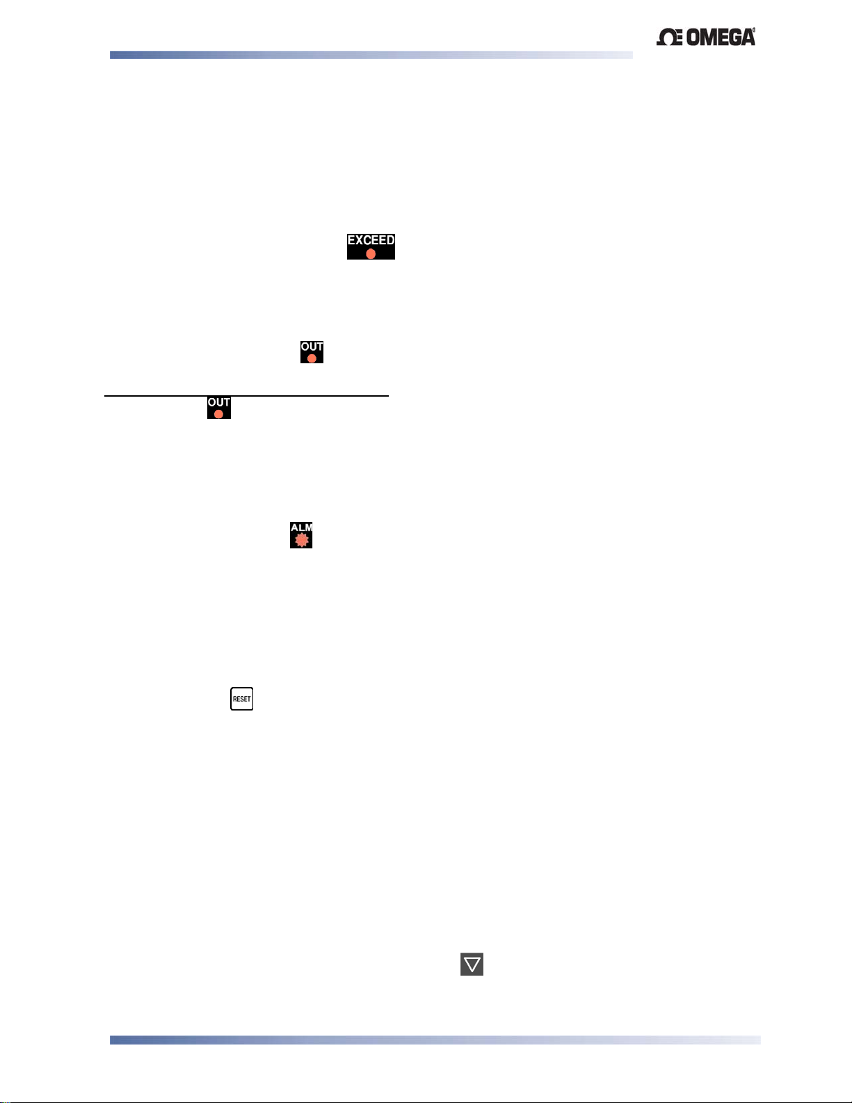
Limit Devices–CN2516, CN2508 and CN2504 Product Manual
Limit Setpoint Adjustment
Adjustment of the Limit Setpoint can be only made from Setup Mode.
Exceed Condition
An Exceed Condition occurs when the Process Variable exceeds the Limit Setpoint value (i.e.
PV is greater than the Limit Setpoint when set for high limit action, PV is less than the Limit
Setpoint for low limit action). The LED is on during this condition, and is extinguished
once it has passed.
Limit Output Function
The Limit Output relay(s) de-energize whenever an Exceed condition occurs, causing the
process to shut down. The LED is on when the relay is de-energized.The relay remains
latched off even if the Exceed condition is no longer present. A reset instruction must be given
after the exceed condition has passed to re-energize the relay, allowing the process to
continue. The LED then turns off.
Limit Annunciator Outputs
An Annunciator output will activate when an Exceed condition occurs, and will remain active
until a reset instruction is received, or the Exceed condition has passed. Unlike the Limit
Output, an Annunciator can be reset even if the Exceed condition is present. When an
Annunciator is active, the LED will flash and the Alarm Status screen is available.
Resetting Limit Outputs & Annunciators
A reset instruction can be given by any of the following methods. The front panel Reset key, the
Digital Input (if fitted) or via Serial Communications command if an RS485 Communications
module is fitted.
Using the Reset Key to Reset Limit Outputs & Annunciators
Press the key to reset an active Annunciator or latched Limit Relay.
Note: Annunciators will deactivate immediately, Limit Outputs will only re-energize if the
Exceed condition has passed.
CAUTION:
Insure that the cause of the Exceed condition has been rectified before resetting the
Limit Output.
Resetting Limit Hold and Exceed Time
The highest PV value reached (for High Limit action) or lowest PV value reached (for Low Limit
action) and the accumulated time of Limit SP exceed conditions can be viewed.
To reset the stored Limit Hold and Exceed Time values
Display the value to be reset, the press the key for 5 seconds. The upper display
briefly shows
when the value is reset.
CN2516, CN2508 & CN2504 – Model Group Page 37
Page 46
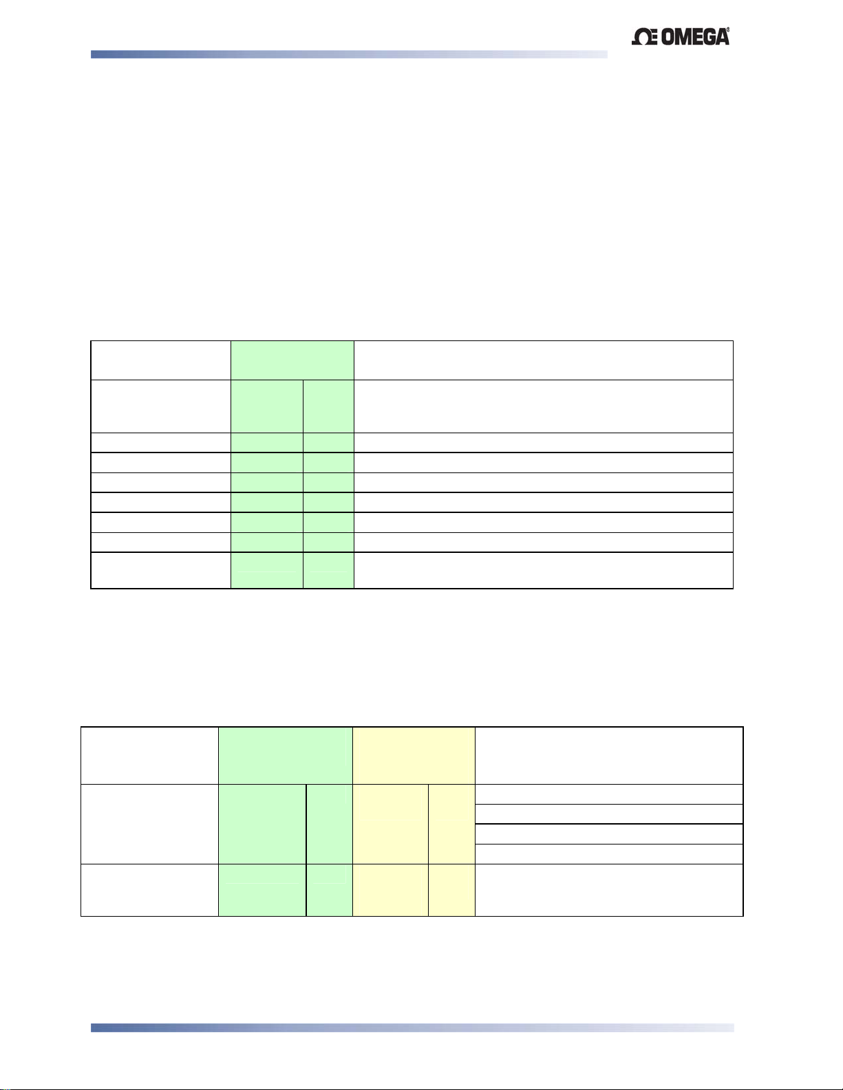
Limit Devices–CN2516, CN2508 and CN2504 Product Manual
CN2516, CN2508 & CN2504 Devices – Serial Communications Parameters
The Modbus parameter addresses, and the possible ASCII message types and parameters
indents for the CN2516, CN2508 & CN2504 are detailed below. RO indicates a parameter is
read only, R/W indicates it can also be written to. Communications writes will not implement if
the Communications Write Parameter is disabled. Refer to the Modbus and ASCII
Communications sections of this manual for details of the protocols used.
Bit Parameters
Bit parameters are not applicable to the ASCII protocol.
Table 12. CN2516, CN2508 & CN2504 Communications - Bit
Parameters
Parameter
Modbus
Notes
Parameter No.
Communication
Write Status
Limit Action 2 RO 1 = Low Limit, 0 = High Limit
Reset Limit Relay 3 R/W 1 = Reset Latched Relays. A read returns the values 0
Limit Status 4 RO 1 =In Exceed Condition, 0 = Not in Exceed Condition
Alarm 1 Status 5 RO 1 = Active, 0 = Inactive
Alarm 2 Status 6 RO 1 = Active, 0 = Inactive
Limit Output Status 7 RO 1 = Relay latched, 0 = Relay not latched
Annunciator Output
Status
To set the bit value to 1 write FF, to set the bit value to 0 write 00. Refer to Function Code 05 in the
Modbus Communications section.
1 RO 1 = Write Enabled, 0 = Write Disabled. A negative
acknowledgement (exception code 3) is sent to write
commands if communications writes are disabled
8 RO 1 = Active, 0 = Inactive
Word Parameters
Table 13. CN2516, CN2508 & CN2504 Communications - Word
Parameters
Parameter
Modbus
Parameter No.
ASCII Ident &
Message
Notes
Types
Process Variable
Limit Setpoint 2 R/W S
1 RO M
Type 2
Type 2,
3/4
RO
R/W
Current value of PV.
If under-range = 62976 (<??>5 ASCII)
If over-range = 63232 (<??>0 ASCII)
If Sensor break = 63488 (ASCII = n/a)
Value of the Limit Setpoint.
CN2516, CN2508 & CN2504 – Model Group Page 38
Page 47
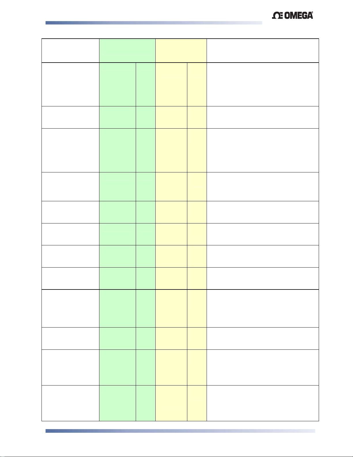
Limit Devices–CN2516, CN2508 and CN2504 Product Manual
Parameter Modbus
Parameter No.
ASCII Ident &
Message
Hold Value 3 R/W A
Type 2
Deviation 4 RO V
Type 2
Time Exceeded
Value
5 R/W T
Type 2
Limit Hysteresis 6 R/W F
Type 2,
3/4
Alarm 1 Value 7 R/W C
Type 2,
3/4
Alarm 2 Value 8 R/W E
Type 2,
3/4
Scale Range
Lower Limit
9 R/W H
Type 2
Type 3/4
Scale Range
Upper Limit
10 R/W G
Type 2
Type 3/4
Decimal Point
Position
11 R/W Q
Type 2
Type 3/4
Input Filter Time
Constant
12 R/W m
Type 2,
3/4
Re-transmit output
Maximum
13 R/W [
Type 2,
3/4
Re-transmit Output
Minimum
14 R/W \
Type 2,
3/4
Types
RO
RO
RO
R/W
R/W
R/W
RO
R/W
RO
R/W
RO
R/W
R/W
R/W
R/W
Notes
Highest PV value (High Limit Action) or
Lowest PV value (Low Limit Action)
since this parameter was last reset.
Modbus: Write any value to reset
ASCII: See Controller Command
00160 for reset.
Difference between Process Variable
and Limit Setpoint (value = PV-Limit
SP)
Accumulated time of Limit SP exceed
conditions since this parameter was last
reset.
Modbus: Write any value to reset
ASCII: See Controller Command
00170 for reset
A band on the “safe” side of the Limit
SP. Adjustable 0 to 100% of span. A
latched limit relay cannot be reset until
the process passes through this band
Alarm 1 active at this level
Alarm 2 active at this level
Lower limit of scaled input range
Upper limit of scaled input range
Read only if not Linear Input.
0 = xxxx
1 = xxx.x
2 = xx.xx
3 = x.xxx
0 to 100 seconds
Maximum scale value for retransmit
output, 1999 to 9999. This parameter
applies to the first re-transmit output
fitted (see also Modbus parameters
2224, 2225, 2234 & 2235).
Minimum scale value for retransmit
output, 1999 to 9999. This parameter
applies to the first re-transmit output
fitted (see also Modbus parameters
2224, 2225, 2234 & 2235).
CN2516, CN2508 & CN2504 – Model Group Page 39
Page 48
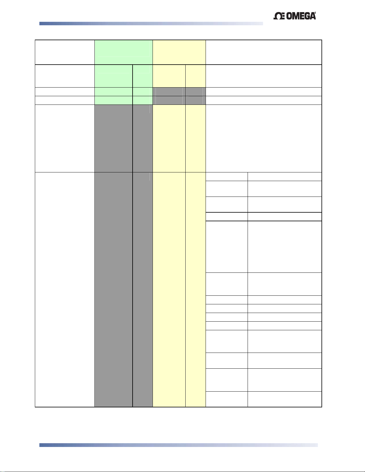
Limit Devices–CN2516, CN2508 and CN2504 Product Manual
Parameter Modbus
Parameter No.
ASCII Ident &
Message
Notes
Types
Process Value
Offset
Alarm 1 Hysteresis 32 R/W 0 to 100% of span
Alarm 2 Hysteresis 33 R/W 0 to 100% of span
Controller
Commands
Controller Status L
26 R/W v
Type 2
Type 3/4
Z
Type 3/4 R/W
Type 2
RO
R/W
RO
Modified PV = Actual PV + PV Offset.
Limited by Scale Range Max. and Scale
Range Min.
The Type 3 {DATA} field must be one of
three five-digit numbers:
00150 = Reset Limit Outputs
00160 = Reset Hold Value
00170 = Reset Exceed Time value
The response contains the same
{DATA}. A negative acknowledgement
will be returned if Reset in not possible
or already implemented.
Bits Meaning
0 Alarm 1 status:
0 = Activated, 1 = Safe
1 Alarm 2 status:
0 = Activated, 1 = Safe
2 Not used
3 Change Indicator:
0 = No changes, since
Controller Status was
last read.
1 = A parameter other
than Controller Status or
PV has changed
4 Comms write status:
0 = Disabled
1 = Enabled
5 Not used
6 Not used
7 Not used
8 Not used
9 Limit status:
0 = Not Exceeded, 1 =
Exceeded
10 Limit Relay Status:
0 = safe, 1 = Latched Off
11 Limit Action:
0 = Low Limit, 1 = High
Limit
12 Annunciator status:
0 = inactive, 1 = Active
CN2516, CN2508 & CN2504 – Model Group Page 40
Page 49
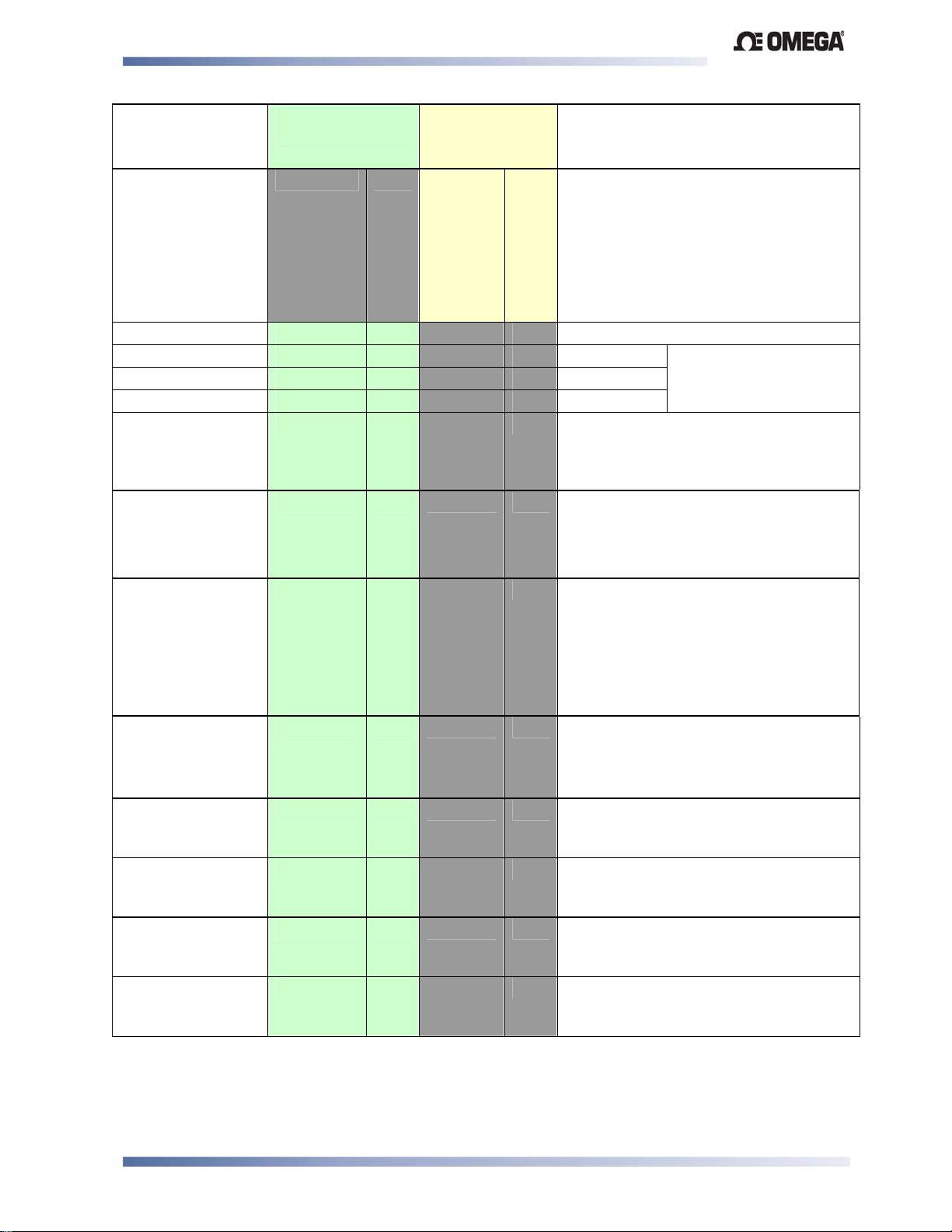
Limit Devices–CN2516, CN2508 and CN2504 Product Manual
Parameter Modbus
Parameter No.
ASCII Ident &
Message
Notes
Types
Scan Table ]
Type 2
Equipment ID 122 RO The four digit model number 6700
Serial Number Low 123 RO Digits aaaa Unit serial number.
Serial Number Mid 124 RO Digits bbbb
Serial Number High 125 RO Digits cccc
Date of
manufacture
Product Revision
Level
Firmware Version 130 RO
126 RO Manufacturing date code as an
129 RO
Reads back main process values.
RO
Response is: L{N}25aaaaabbbbb
cccccdddddeeeeeA* where:
aaaaa = Limit Setpoint value
bbbbb = Process Variable value
ccccc = Hold value
ddddd = Exceeded Time value
eeeee = Controller Status (see above)
Format aaaa bbbb cccc,
(12 BCD digits).
encoded binary number.
E.g. 0403 for April 2003 is returned as
193hex
Low Byte
High Byte
Alpha part of PRL.
E.g. A = 01hex
Numeric part of PRL.
E.g. 13 = 0Dhex
Bits Meaning
0 - 4
Revision number (1,2...)
5 - 9
10 - 15
Input status 133 RO Input status. Read Only.
Bit 0: Sensor break flag
Bit 1: Under-range flag
Bit 2: Over-range flag
Option Slot 2
Re-transmit output
Maximum
Option Slot 2
Re-transmit output
Minimum
Option Slot 3
Re-transmit output
Maximum
Option Slot 3
Re-transmit output
Minimum
2224 R/W Maximum scale value for retransmit
output in slot 2, 1999 to 9999.
2225 R/W Minimum scale value for retransmit
output in slot 2, 1999 to 9999.
2234 R/W Maximum scale value for retransmit
output in slot 3, 1999 to 9999.
2235 R/W Minimum scale value for retransmit
output in slot 3, 1999 to 9999.
Alpha version (A=0,
B=1...)
Numeric version
(starting from 121 = 0)
Note:
Some of the parameters that do not apply to a particular configuration will accept reads
and writes (e.g. attempting to scale a Linear output which has not been fitted). Read only
parameters will return an exception if an attempt is made to write values to them.
CN2516, CN2508 & CN2504 – Model Group Page 41
Page 50

Limit Devices–CN2516, CN2508 and CN2504 Product Manual
9 Modbus Serial Communications
All models support the Modbus RTU communication protocol. Some models also support an
ASCII communication protocol. Where both Modbus and ASCII are supported, the protocol to
be used is selected from Configuration Mode. The RS485 Communications Module must be
fitted into Option Slot A in order to use serial communications.
Refer to the relevant Model Group Section for the ASCII and Modbus Application Layer
(parameter address/ident information).
For a complete description of the Modbus protocol refer to the description provided at
http://www.modicon.com/ or http://www.modbus.org/
Physical Layer
The Base address, bit rate and character format are configured via the front panel in
Configuration Mode or by using the PC Configurator software.
Physical layer configuration settings possible are:
Data rate: 1200, 2400, 4800 (default), 9600 and 19,200 bps
Parity: None (default), Even, Odd
Character format: Always 8 bits per character.
The transmitter must not start transmission until 3 character times have elapsed since reception
of the last character in a message, and must release the transmission line within 3 character
times of the last character in a message.
Note:
Three character times = 1.5ms at 19200, 3ms at 9600, 6ms at 4800, 12ms at 2400 and
24ms at 1200 bps.
Modbus Communications Page 42
Page 51
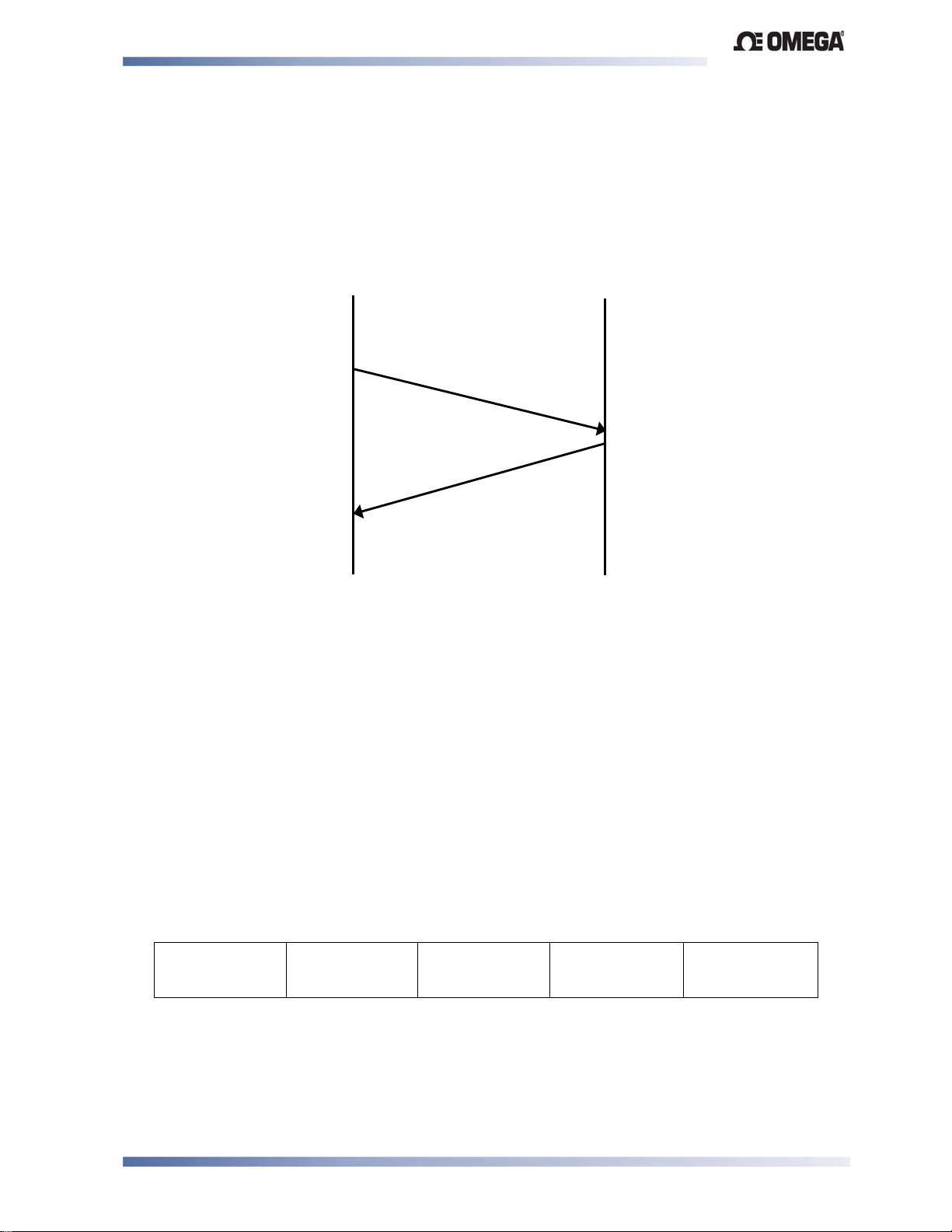
Limit Devices–CN2516, CN2508 and CN2504 Product Manual
Link Layer
A Query (or command) is transmitted from the Modbus Master to the Modbus Slave. The slave
instrument assembles the reply to the master. All of the instruments covered by this manual are
slave devices, and cannot act as a Modbus Master.
MODBUS
MASTER
SLAVE
INSTRUMENT
QUERY
RESPONSE
Figure 30. Modbus Link Layer
A message for either a QUERY or RESPONSE is made up of an inter-message gap followed
by a sequence of data characters. The inter-message gap is at least 3.5 data character times.
Data is encoded for each character as binary data, transmitted LSB first.
For a QUERY the address field contains the address of the slave destination. The slave
address is given together with the Function and Data fields by the Application layer. The CRC is
generated from the given address, function and data characters.
For a RESPONSE the address field contains the address of the responding slave. The Function
and Data fields are generated by the slave application. The CRC is generated from the
address, function and data characters.
The standard MODBUS RTU CRC-16 calculation employing the polynomial 2
16+215+22
+1 is
used.
Inter-message
gap
Address
1 character
Function
1 character
Data
n characters
CRC Check
2 characters
Modbus Communications Page 43
Page 52
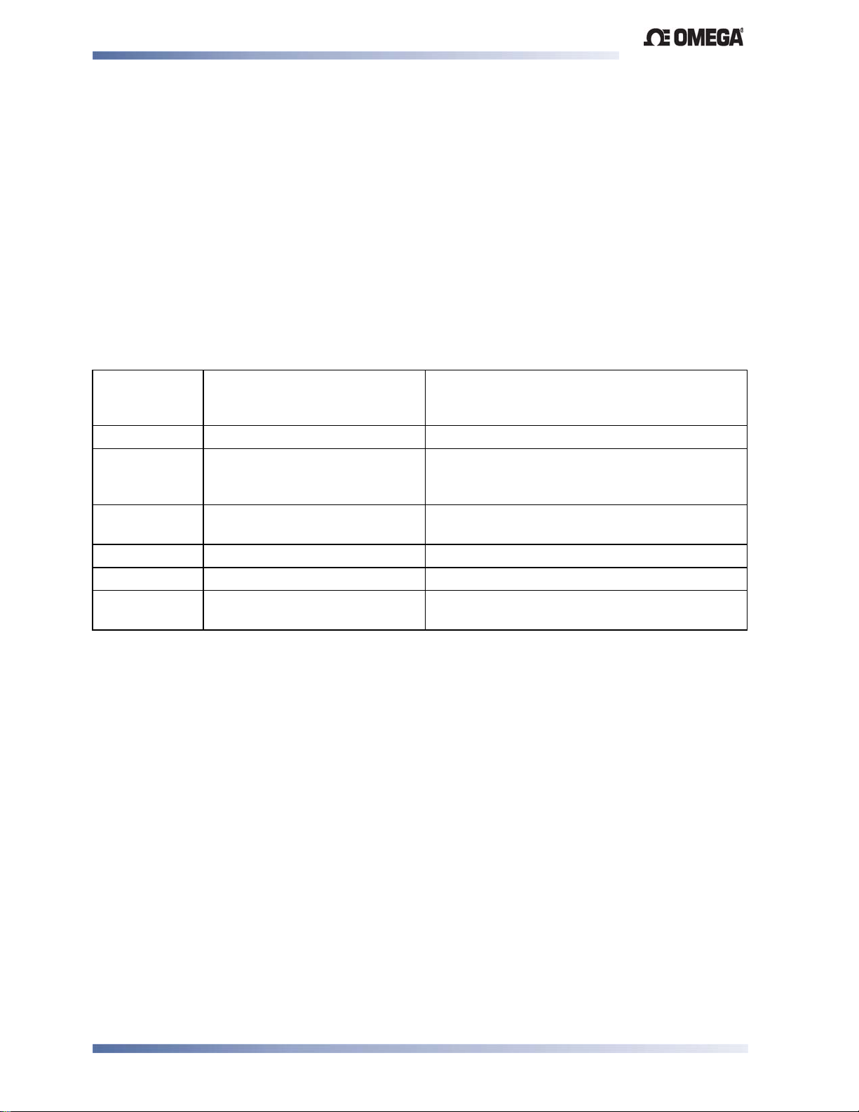
Limit Devices–CN2516, CN2508 and CN2504 Product Manual
Device Addressing
The instrument is assigned a unique device address by the user in the range 1 (default) to 255
using the
==+ parameter in Configuration Mode. This address is used to recognise Modbus
Queries intended for this instrument. The instrument does not respond to Modbus Queries that
do not match the address that has been assigned to it.
The instrument will also accept global Queries using device address 0 no matter what device
address is assigned. No responses are returned for globally addressed Queries.
Supported Modbus Functions
Modbus defines several function types; these instruments support the following types:
Table 14. Supported Modbus Functions
Function
Modbus Meaning Description
Code
(decimal)
01 / 02 Read Coil/Input Status Read output/input status bits at given address.
03 / 04 Read Holding/Input registers Read current binary value of specified number
of parameters at given address. Up to 64
parameters can be accessed with one Query.
05 Force single Coil Writes a single binary bit to the Specified Slave
Bit address.
06 Pre-set Single Register Writes two bytes to a specified word address.
08 Diagnostics Used for loopback test.
16 Pre-set Multiple Registers Writes up to 1 word parameter values to the
specified address range.
Function Descriptions
The following is interpreted from the Modbus Protocol Description obtainable from
http://www.modicon.com/ or http://www.modbus.org/. Refer to that document if clarification is
required.
In the function descriptions below, the preceding device address value is assumed, as is the
correctly formed two-byte CRC value at the end of the QUERY and RESPONSE frames.
Modbus Communications Page 44
Page 53
Limit Devices–CN2516, CN2508 and CN2504 Product Manual
Read Coil/Input Status (Function 01 / 02)
Reads the content of instruments output/input status bits at the specified bit address.
Table 15. Read Coil/Input Status (Modbus Function 01/02)
QUERY
Function Address of 1st Bit Number of Bits
01 / 02 HI LO HI LO
RESPONSE
Function Number of Bytes First 8 bits 2nd 8 Bits
01 / 02
In the response the “Number of Bytes” indicates the number of data bytes read from the
instrument. E.g. if 16 bits of data are returned then the count will be 2. The maximum number of
bits that can be read is 16 in one transaction. The first bit read is returned in the least significant
bit of the first 8 bits returned.
Read Holding/Input Registers (Function 03 / 04)
Reads current binary value of data at the specified word addresses.
Table 16. Read Holding/Input Registers (Modbus Function
03/04)
QUERY
Function Address of 1
03 / 04 HI LO HI LO
st
Word Number of Words
RESPONSE
Function Number of
Bytes
03 / 04 HI LO HI LO
First Word
Last Word
In the response the “Number of Bytes” indicates the number of data bytes read from the
instrument. E.g. if 5 words are read, the count will be 10 (A hex). The maximum number of
words that can be read is 64. If a parameter does not exist at one of the addresses read, then a
value of 0000h is returned for that word.
Modbus Communications Page 45
Page 54
Limit Devices–CN2516, CN2508 and CN2504 Product Manual
Force Single Coil (Function 05)
Writes a single binary value to the Specified Instrument Bit address.
Table 17. Force Single Coil (Modbus Function 05)
QUERY
Function Address of Bit State to write
05 HI LO FF/00 00
RESPONSE
Function Address of Bit State written
05 HI LO FF/00 00
The address specifies the address of the bit to be written to. The State to write is FF when the
bit is to be SET and 00 if the bit is to be RESET.
Note:
The Response normally returns the same data as the Query.
Pre-Set Single Register (Function 06)
Writes two bytes to a specified word address.
Table 18. Pre-Set Single Register (Modbus Function 06)
QUERY
Function Address of Word Value to write
06 HI LO HI LO
RESPONSE
Function Address of Word Value written
06 HI LO HI LO
Note:
The Response normally returns the same data as the Query.
Loopback Diagnostic Test (Function 08)
Table 19. Loopback Diagnostic Test (Modbus Function 08)
QUERY
Function Diagnostic Code Value
08 HI =00 LO=00 HI LO
RESPONSE
Function Sub-function Value
08 HI=00 LO=00 HI LO
Note:
The Response normally returns the same data as the Query.
Modbus Communications Page 46
Page 55
Limit Devices–CN2516, CN2508 and CN2504 Product Manual
Pre-Set Multiple Registers (Function 10 Hex)
Writes a consecutive word (two-byte) value to the specified address range.
Table 20. Pre-Set Multiple Registers (Modbus Function 10 Hex)
Function 1
10 HI LO HI LO HI LO
st
Word
Address
Number of
Words
Number of
Query Bytes
First value to write
RESPONSE
Function 1st Word Address Number of Words
QUERY
10 HI LO HI LO
Note:
The number of consecutive words that can be written is limited to 1.
Exception Responses
When a QUERY is sent that the instrument cannot interpret then an Exception RESPONSE is
returned. Possible exception responses are:
Table 21. Modbus Exception Responses
Exception
Error Condition Interpretation
Code
00
01
Unused
Illegal function Function number out of range.
None.
02
03
Illegal Data Address Write functions: Parameter number out of range or not
supported. (for write functions only).
Read Functions: Start parameter does not exist or end
parameter greater than 65536.
Illegal Data Value Attempt to write invalid data / required action not
executed.
The format of an exception response is:
RESPONSE
Function Exception Code
Original Function code with its Most
Significant Bit
(MSB) set.
as detailed above
Note:
In the case of multiple exception codes for a single QUERY the Exception code returned is
the one corresponding to the first parameter in error.
Modbus Communications Page 47
Page 56

Limit Devices–CN2516, CN2508 and CN2504 Product Manual
10 ASCII Communications
This is simple ASCII protocol provides backwards compatibility with some older products. ASCII
is not available in all models in the range. The Modbus protocol is recommended for future use.
Refer to the relevant Model Group Section for the ASCII and Modbus Application Layer
(parameter address/ident information).
Physical Layer
The Base address, bit rate and character format are configured via the front panel in
Configuration Mode or by using the PC Configurator software.
Physical layer configuration settings possible are:
Data rate: 1200, 2400, 4800 (default), 9600 and 19,200 bps
Parity: Even
Character format: 7 bits per character. + 1 stop bit.
The transmitter must not start transmission until 3 character times have elapsed since reception
of the last character in a message, and must release the transmission line within 3 character
times of the last character in a message.
Note:
Three character times = 1.5ms at 19200, 3ms at 9600, 6ms at 4800, 12ms at 2400 and
24ms at 1200 bps.
Device Addressing
The instrument is assigned a device address by the user using the ==+ parameter in
Configuration Mode. The address may be set to any unique value from 1 (default) to 99. This
address is used to recognise ASCII messages intended for this instrument. The instrument
does not respond to messages that do not match the address that has been assigned to it.
Session Layer
The ASCII protocol assumes half duplex communications. The master device initiates all
communication. The master sends a command or query to the addressed slave instrument and
the slave replies with an acknowledgement of the command or the reply to the query.
Messages from the master device may be one of five types:
Type 1: {S}{N}??*
Type 2: {S}{N}{P}{C}* or R{N}{P}{C}*
Type 3: {S}{N}{P}#{DATA}* or R{N}{P}#{DATA}*
Type 4: {S}{N}{P}I* or R{N}{P}I*
Type 5: {S} {N} \ P S S ? *
All characters are in ASCII code. See the following Parameter Key table for details of the
parameters in brackets { }.
ASCII Communications Page 48
Page 57
Limit Devices–CN2516, CN2508 and CN2504 Product Manual
Table 22. ASCII Parameter Key
{S}
{N}
{P}
{C}
#
{DATA}
P
S S
*
is the Start of Message character L (Hex 4C) or R (Hex 52).
L is used for Controllers; R is used for Profilers.
is the slave device address (in the range 1 - 99); addresses 1 - 9 may be represented
by a single digit (e.g. 7) or in two-digit form, the first digit being zero (e.g. 07).
is a character which identifies the parameter to be interrogated/modified.
is the command (Refer to the Serial Communications Application Layer
information for each Model Group
indicates that {DATA} is to follow (Hex 23)
is a string of numerical data in ASCII code (refer to the Data Element table below)
is the Program Number
is the Segment Number (01 to 16)
is the End of Message Character (Hex 2A)
)
No space characters are permitted in messages. Any syntax errors in a received message will
cause the slave instrument to issue no reply and await the Start of Message character.
Table 23. ASCII Data Element – Sign/Decimal Point Position
{DATA} Content Data Format Description
abcd0 +abcd
Positive value, no decimal place
abcd1 +abc.d
abcd2 +ab.cd
abcd3 +a.bcd
Abcd5 - abcd
Abcd6 - abc.d
Abcd7 - ab.cd
Abcd8 - a.bcd
Positive value, one decimal place
Positive value, two decimal places
Positive value, three decimal places
Negative value, no decimal place
Negative value, one decimal place
Negative value, two decimal places
Negative value, three decimal places
(In the Data Content, abcd represents the data value, the last digit indicates data format)
Type 1 Message
L {N} ? ? *
This message is used by the master device to determine whether the addressed slave device is
active.
The reply from an active slave is
L {N} ? A *
An inactive device will give no reply.
ASCII Communications Page 49
Page 58

Limit Devices–CN2516, CN2508 and CN2504 Product Manual
Type 2 Message
L {N} {P} {C} * or R {N} {P} {C} *
This type of message is used by the master device, to interrogate or modify a parameter in the
addressed slave device. {P} identifies the parameter and {C} represents the command to be
executed, which may be one of the following:
+ (Hex 2B) = Increment the value of the parameter defined by {P}
– (Hex 2D) = Decrement the value of the parameter defined by {P}
? (Hex 3F) = Determine the current value of the parameter defined by {P}
The reply from the addressed slave device is of the form:
L {N} {P} {DATA} A * or R {N} {P} {DATA} A *
where {DATA} comprises five ASCII-coded digits whose format is shown in the
above. The data is the value requested in a query message or the new value of the
table
Data Element
parameter after modification. If the action requested by the message from the master device
would result in an invalid value for that parameter (either because the requested new value
would be outside the permitted range for that parameter or because the parameter is not
modifiable), the slave device replies with a negative acknowledgement:
L {N} {P} {DATA} N * or R {N} {P} {DATA} N *
The {DATA} string in the negative acknowledgement reply will be indeterminate. If the process
variable or the deviation is interrogated whille the process variable is outside the range of the
slave device, the reply is:
L {N} {P} < ? ? > 0 A *
if the process variable is over-range, or
L {N} {P} < ? ? > 5 A *
if the process variable is under-range.
Type 3 Message
L {N} {P} # {DATA} * or R {N} {P} # {DATA} *
This message type is used by the master device to set a parameter to the value specified in
{DATA}. The command is not implemented immediately by the slave device; the slave will
receive this command and will then wait for a Type 4 message (see below). Upon receipt of a
Type 3 message, if the {DATA} content and the specified parameter are valid, the slave device
reply is of the form:
L {N} {P} {DATA} I * or R {N} {P} {DATA} I *
(where I = Hex 49) indicating that the slave device is ready to implement the command. If the
parameter specified is invalid or is not modifiable or if the desired value is outside the permitted
range for that parameter, the slave device replies with a negative acknowledgement in the form:
L {N} {P} {DATA} N * or R {N} {P} {DATA} N *
ASCII Communications Page 50
Page 59

Limit Devices–CN2516, CN2508 and CN2504 Product Manual
Type 4 Message
L {N} {P} I * or R {N} {P} I *
This type of message is sent by the master device to the addressed slave device, following a
successful Type 3 transaction with the same slave device. Provided that the {DATA} content
and the parameter specified in the preceding Type 3 message are still valid, the slave device
will then set the parameter to the desired value and will reply in the form:
L {N} {P} {DATA} A *
where {DATA} is the new value of the parameter. If the new value or parameter specified is
invalid, the slave device will reply with a negative acknowledgement in the form:
L {N} {P} {DATA} N *
where {DATA} is indeterminate. If the immediately preceding message received by the slave
device was not a Type 3 message, the Type 4 message is ignored.
Error Response
The circumstances under which a message received from the master device is ignored are:
Parity error detected
Syntax error detected
Timeout elapsed
Receipt of a Type 4 message without a preceding Type 3 command message.
Negative acknowledgements will be returned if, in spite of the received message being
notionally correct, the slave device cannot supply the requested information or perform the
requested operation. The {DATA} element of a negative acknowledgement will be
indeterminate.
ASCII Communications Page 51
Page 60

Limit Devices–CN2516, CN2508 and CN2504 Product Manual
11 Calibration Mode
WARNING:
CALIBRATION IS ONLY REQUIRED FOR INSTRUMENTS IN WHICH CALIBRATION ERR O RS
HAVE BEEN ENCOUNTERED. REFER TO CALIBRATION CHECK BELOW.
CAUTION:
Calibration must be performed by personnel who are technically competent and
authorized to do so.
Calibration is carried out during manufacture and is not normally required again during the
lifetime of an instrument.
Equipment Required For Checking or Calibrating the Universal Input
A suitable calibration signal source is required for each input type. To verify the accuracy of the
instrument or carry out recalibration, the listed input sources are required, with better than
±0.05% of the reading accuracy:
1. DC linear inputs: 0 to 50mV, 0 to 10VDC and 0 to 20mADC.
2. Thermocouple inputs - complete with 0ºC reference facility, appropriate thermocouple
functions and compensating leads (or equivalent).
3. RTD inputs: decade resistance box with connections for three-wire input (or equivalent).
Calibration Check
1. Set the instrument to the required input type.
2. Power up the instrument and connect the correct input leads.
Leave powered up for at least five minutes for RTD and DC linear inputs, or at least 30
minutes for thermocouple inputs.
3. After the appropriate delay for stabilisation has elapsed, check the calibration by
connecting the appropriate input source and checking a number of cardinal points.
4. Repeat the test for all required input types.
Calibration Page 52
Page 61

Limit Devices–CN2516, CN2508 and CN2504 Product Manual
Recalibration Procedure
Recalibration is carried out in five phases as shown in the table below, each phase corresponds
to an input range of the instrument.
CAUTION:
The 50mV phase MUST be calibrated before the thermocouple range.
Table 24. Input Calibration phases
): 50 mV
): 10 V
): 20 mA
): RTD input (200 ohm)
): Thermocouple (K type source at 0ºC required)
To start calibration, apply the required calibration input from the source type list above, using
the correct connections,
1. While the instrument is powering up, press and together until
): is
displayed.
Note:
If a phase has not been previously calibrated the display will flash.
2. Press to initiate calibration
3. During calibration the display changes to
for a few seconds.
4. If the input is misconnected or an incorrect signal is applied the calibration will be
aborted and the display will shown
"'. The previous calibration value will be retained.
5. If the calibration has succeeded, the pass display is shown
): (non-flashing).
6. Press to step onto the next phase.
7. Repeat this process for each input type until all the phases are calibrated.
Note:
Switch off the instrument to exit the Calibration Mode.
Calibration Mode automatically exits if there is no button activity for five minutes.
Calibration Page 53
Page 62
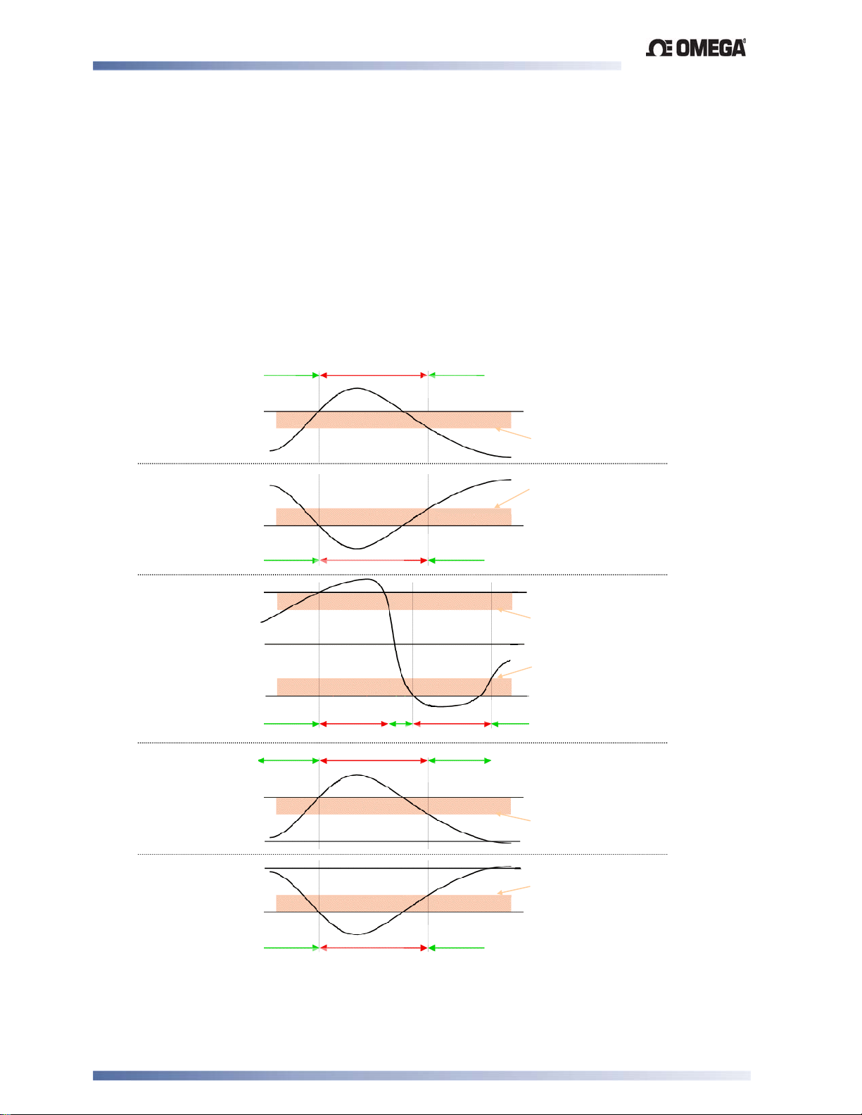
Limit Devices–CN2516, CN2508 and CN2504 Product Manual
A
A
A
(
A
A
A
A
A
A
(
(
(
12 Appendix 1 – Glossary
This Glossary explains the technical terms and parameters used in this manual. The entry type
is also shown:
Limit Device Definition:
Limit Device Parameter:
Alarm Hysteresis
Type: Limit Device Parameter
An adjustable band on the “safe” side of an alarm point, through which the process variable
must pass before the alarm will change state, as shown in the diagram below. E.g. a high
alarm’s hysteresis band is below the high alarm value, and a low alarm’s hysteresis is above
the low alarm value.
Also refer to Alarm Operation.
Inactive
PROCESS
HIGH ALARM
Process Variable
Process Variable
PROCESS
LOW ALARM
Inactive
Process Variable
BAND ALARM
Inactive
larm Value
larm Hysteresis Value
larm Hysteresis Value
larm Value
Inactive
Alarm Value
from Setpoint)
larm Hysteresis Value
Setpoint
larm Hysteresis Value
Alarm Value
from Setpoint)
Alarm Value
from Setpoint)
larm Hysteresis Value
Setpoint
Setpoint
larm Hysteresis Value
Alarm Value
from Setpoint)
DEVIATION
HIGH ALARM
Process Variable
Process Variable
DEVIATION
LOW ALARM
Inactive
Inactive
Alarm Inactive
Inactive
Inactive
Inactiv
larm Inactive
Alarm Act ive
Figure 31. Alarm Hysteresis Operation
Glossary Page 54
Page 63
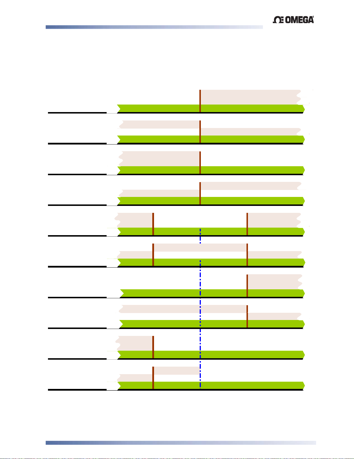
Limit Devices–CN2516, CN2508 and CN2504 Product Manual
Al
Off
Al
Al
Off
Al
Al
Off
Al
Al
Off
Al
Al
Al
Al
Al
Al
Al
Al
Al
Al
Off
Al
Al
Off
Al
Al
Off
Al
Al
Off
Al
A
A
Alarm Operation Type: Limit Device Definition
The different alarm types are shown below, together with the action of any outputs.
Also refer to Alarm Hysteresis, Alarm Inhibit, Band Alarm, Deviation Alarm, Latching Relay,
Logical Alarm Combinations, Loop Alarm, Process High Alarm and Process Low Alarm.
Process High Alarm
Direct-Acting
Process High Alarm
Reverse-Acting
Process Low Alarm
Direct-Acting
Process Low Alarm
Reverse-Acting
Band Alarm
Direct-Acting
Band Alarm
Reverse-Acting
Output Off..Output On
arm
Output On..Output Off
arm
Output On..Output Off
arm On..Alarm
Output Off..Output On
arm On..Alarm
Output On..Output On
arm On..
arm Value
Output Off.
arm On..
arm Value
..Alarm On
arm.Value
..Alarm On
arm.Value
arm.Value
arm.Value
Output Off
larm Off
arm Value
Output On .Output Off
larm Off
arm Value
Process Variable
Process Variable
Process Variable
Process Variable
arm On
Process Variable
arm On
Process Variable
Deviation High
Alarm (+ve val u e s )
Direct-Acting
Deviation High
Alarm (+ve val u e s )
Reverse-Acting
Deviation Low
Alarm (-ve values)
Direct-Acting
Deviation Low
Alarm (-ve values)
Reverse-Acting
Glossary Page 55
Output On..Output Off
arm On..Alarm
arm Value
Output Off..Output On
arm On..Alarm
arm Value
Figure 32. Alarm Operation
Setpoint
Output Off..Output On
arm
arm Value
Output On.
arm
arm Value
..Alarm On
Process Variable
.Output Off
..Alarm On
Process Variable
Process Variable
Process Variable
Page 64

Limit Devices–CN2516, CN2508 and CN2504 Product Manual
Annunciator
Type: Limit Device Definition
A special type of alarm output that is linked to a Limit Controllers main Limit Output. An
Annunciator output will activate when an Exceed condition occurs, and will remain active until a
reset instruction is received, or the Exceed condition has passed. Unlike the Limit Output, an
Annunciator can be reset even if the Exceed condition is present
Also refer to Exceed Condition, Latching Relay, Limit Controller, Limit Hysteresis and Limit
Setpoint
Band Alarm 1 Value
Type: Limit Device Parameter
This parameter is applicable only if Alarm 1 is selected to be a Band Alarm. It defines a band of
process variable values, centered on the current actual setpoint value. If the process variable
value is outside this band, the alarm will be active. This parameter may be adjusted from 1 to
full span from the setpoint.
Display code =
', default value = 5.
Also refer to Alarm Operation, Band Alarm 2 Value and Input Span.
Band Alarm 2 Value
Type: Limit Device Parameter
This parameter is similar to the Band Alarm 1 Value. It is applicable only if Alarm 2 is selected
to be a Band Alarm.
Display code =
', default value = 5.
Also refer to Alarm Operation, Band Alarm 1 Value and Input Span.
Communications Write Enable
Type: Limit Device Definition
This enables/disables the changing of parameter values via the RS485 communications link, if
the communications option is installed. Possible settings are read only or read/write.
Display code =
3 C, default setting = r_ Ww (read/write).
CPU
Type: Limit Device Definition
This stands for Central Processing Unit and refers to the onboard microprocessor that controls
all of the measuring, alarm and control functions of the instrument.
Deviation Alarm 1 Value Type
Type: Limit Device Parameter
This is applicable only if Alarm 1 is selected to be Deviation Alarm. A positive value (Deviation
High) sets the alarm point above the current actual setpoint; a negative value (Deviation Low)
sets it below. If the process variable deviates from the setpoint by a margin greater than this
value, alarm 1 becomes active.
Display code =
=', Default value = 5.
Also refer to Alarm Operation and Deviation Alarm 2 Value.
Deviation Alarm 2 Value
Type: Limit Device Parameter
Applicable only if Alarm 2 is selected as a Deviation Alarm. It is similar to Deviation Alarm 1
Value.
Display code =
='. Default value = 5.
Also refer to Alarm Operation and Deviation Alarm 1 Value.
Glossary Page 56
Page 65

Limit Devices–CN2516, CN2508 and CN2504 Product Manual
Display Strategy
Type: Limit Device Parameter
Alters the parameters displayed in normal operator mode. For example a controller could
display PV + SP, PV + adjustable SP, PV + Ramping SP, PV only or SP only. Display strategy
6 will allow read only access to the setpoint values in Operator Mode, Setup Mode must then be
entered to change the setpoint.
Display code =
=-@
Also refer to Process Variable, Setpoint and Setpoint Ramping.
Exceed Condition
Type: Limit Device Definition
This is a state that occurs when the Process Variable exceeds the Limit Setpoint value. E.g. if
the PV is above the Limit SP when set for high limit action, or below the Limit SP for low limit
action. The Limit Controller will shut down the process when this condition occurs, and cannot
be reset until the Exceed Condition has passed.
Also refer to Annunciator, Exceed Time, Latching Relay, Limit Controller, Limit Hysteresis and
Limit Setpoint.
Exceed Time
Type: Limit Device Definition
The total accumulated time that a Limit Controller has been in the Exceed Condition since this
parameter was last reset.
Also refer to Elapsed Time, Exceed Condition and Limit Controller.
Input Filter Time Constant
Type: Limit Device Parameter
This parameter is used to filter out extraneous impulses on the process variable. The filtered PV
is used for all PV-dependent functions (display control, alarm etc). The time constant is
adjustable from 0.0 seconds (off) to 100.0 seconds in 0.5 second increments.
Display code =
Also refer to Process Variable.
"'/, Default value = 2.0 seconds.
Input Range Type: Limit Device Definition
This is the overall process variable input range and type as selected by the
%C)/ parameter in
Configuration Mode.
Also refer to Input Span.
Input Span
Type: Limit Device Definition
The measuring limits, as defined by the Scale Range Lower and Scale Range Upper Limits.
The trimmed span value is also used as the basis for calculations that relate to the span of the
instrument.
Also refer to Input Range, Scale Range Lower Limit and Scale Range Upper Limit.
Latching Relay
Type: Limit Device Definition
A type of relay that, once it becomes active, requires a reset signal before it will deactivate. This
output is available on Limit controllers and indicator alarms. To successfully deactivate a
latched relay, the alarm or limit condition that caused the relay to become active must first be
removed, and then a reset signal can be applied. This signal may be applied from the
instrument keypad, Digital Input or command via Serial Communication.
Also refer to Alarm Operation, Limit Controller, Limit Hysteresis, Serial Communications.
LED
Type: Limit Device Definition
Light Emitting Diode. LED’s are used as indicator lights (e.g. for the alarm indication). The
upper and lower 7-segment displays are also LED’s.
Glossary Page 57
Page 66

Limit Devices–CN2516, CN2508 and CN2504 Product Manual
Limit Device
Type: Limit Device Definition
This is a protective device that will shut down a process at a preset Exceed Condition, in order
to prevent possible damage to equipment or products. A fail-safe latching relay is used, which
cannot be reset by the operator until the process is back in a safe condition. This signal may be
applied from the instrument keypad, Digital Input or command via Serial Communication. Limit
controllers work independently of the normal process controller. Limit Controllers have specific
approvals for critical applications. They are recommended for any process that could potentially
become hazardous under fault conditions.
Also refer to Annunciator, Controller, Exceed Condition, Exceed Time, Latching Relay, Limit
Hysteresis, Limit Setpoint and Serial Communications.
Limit Hysteresis
Type: Limit Device Definition
This is an adjustable band on the “safe” side of the Limit Setpoint. For a high limit, the
hysteresis band is below the limit setpoint value, for a low limit, the hysteresis is above the limit
setpoint value. The latching limit relay cannot be reset by the operator until the process has
passed through this band
Also refer to Exceed Condition, Latching Relay, Limit Controller and Limit Setpoint.
Limit Setpoint
Type: Limit Device Definition
This is the preset value at which an Exceed Condition will occur. When a Limit Controller has
been set for High Limit control action, the Exceed Condition is above the Limit Setpoint. When a
Limit Controller has been set for Low Limit control action, the Exceed Condition is below the
Limit Setpoint.
Also refer to Annunciator, Exceed Condition, Limit Hysteresis, Limit Controller and Setpoint.
Lock Codes
Type: Limit Device Parameter
This defines the four-digit codes required to enter Configuration (20) and Set-Up (10).
Display codes =
Logical Combination of Alarms
N'N and -'N -default values shown above in brackets.
Type: Limit Device Definition
Two alarms may be combined logically to create an AND/OR situation. Any suitable output may
be assigned as a Logical Alarm Output, configured for Reverse-acting or Direct action.
Also refer to Alarm Operation
Table 25. Logical Alarm Outputs
Logical OR: Alarm 1 OR Alarm 2
Direct Acting Reverse-Acting
OFF
ON OFF ON ON OFF OFF
OFF ON ON OFF ON OFF
ALARM 1
ON ON ON ON ON OFF
OFF
ALARM 2
OFF
OUTPUT
OFF
ALARM 1
ALARM 2
OFF
ON
OUTPUT
Logical AND: Alarm 1 AND Alarm 2
Direct Acting Reverse-Acting
OFF
ON OFF OFF ON OFF ON
OFF ON OFF OFF ON ON
ALARM 1
ON ON ON ON ON OFF
OFF
ALARM 2
OFF
OUTPUT
OFF
ALARM 1
OFF
ALARM 2
ON
OUTPUT
Glossary Page 58
Page 67

Limit Devices–CN2516, CN2508 and CN2504 Product Manual
mADC
Type: Limit Device Definition
This stands for milliamp DC. It is used in reference to the DC milliamp input ranges and the
linear DC milliamp outputs. Typically, these will be 0 to 20mA or 4 to 20mA.
PLC
Type: Limit Device Definition
This stands for Programmable Logic Controller. A microprocessor based device used in
machine control. It is particularly suited to sequential control applications, and uses “Ladder
Logic” programming techniques. Some PLC’s are capable of basic PID control, but tend to be
expensive and often give inferior levels of control.
Process High Alarm 1 Value
Type: Limit Device Parameter
This parameter, applicable only when Alarm 1 is selected to be a Process High alarm, defines
the process variable value above which Alarm 1 will be active. Its value may be adjusted
between Scale Range Upper Limit and Scale Range Lower Limit.
Display code =
)$, Default value = Scale Range Upper Limit.
Also refer to Alarm Operation, Process High Alarm 2 Value, Process Variable, Scale Range
Lower Limit and Scale Range Upper Limit.
Process High Alarm 2 Value
Type: Limit Device Parameter
This parameter is applicable only when Alarm 2 is selected to be a Process High alarm. It is
similar to the Process High Alarm 1 Value.
Display code =
)$, Default value = Scale Range Upper Limit.
Also refer to Alarm Operation, Process High Alarm 1 Value, Process Variable, Scale Range
Lower Limit and Scale Range Upper Limit.
Process Low Alarm 1 Value
Type: Limit Device Parameter
This parameter, applicable only when Alarm 1 is selected to be a Process low alarm, defines
the process variable value below which Alarm 1 will be active. Its value may be adjusted
between Scale Range Upper Limit and Scale Range Lower Limit.
Display code =
)', Default value = Scale Range Lower Limit.
Also refer to Alarm Operation, Process Low Alarm 2 Value, Process Variable, Scale Range
Lower Limit and Scale Range Upper Limit.
Process Low Alarm 2 Value
Type: Limit Device Parameter
This parameter is applicable only when Alarm 2 is selected to be a Process low alarm. It is
similar to the Process Low Alarm 1 Value.
Display code =
)', default value = Scale Range Lower Limit.
Also refer to Alarm Operation, Process Low Alarm 1 Value, Process Variable, Scale Range
Lower Limit and Scale Range Upper Limit.
Process Variable (PV)
Type: Limit Device Definition
Process Variable is the variable to be measured by the primary input of the instrument. The PV
can be any parameter that can be converted into a electronic signal suitable for the input.
Common types are Thermocouple or PT100 temperature probes, or pressure, level, flow etc
from transducers which convert these parameters into linear DC signals (e.g. 4 to 20mA).
Linear signals can be scaled into engineering units using the Scale Range Lower Limit and
Scale Range Upper Limit parameters.
Also refer to Input Span, Offset, Scale Range Lower Limit and Scale Range Upper Limit.
Glossary Page 59
Page 68

Limit Devices–CN2516, CN2508 and CN2504 Product Manual
Process Variable Offset
Type: Limit Device Parameter
- Refer to Offset.
Retransmit Output
Type: Limit Device Definition
A linear DC voltage or mA output signal, proportional to the Process Variable or Setpoint, for
use by slave controllers or external devices, such as a Data Recorder or PLC. The output can
be scaled to transmit any portion of the input or setpoint span.
Also refer to Input Span, Master & Slave, Process Variable and Setpoint.
Retransmit Output 2 Scale Maximum
Type: Limit Device Parameter
Scales a linear output module in slot 2 that has been set up to retransmit PV or SP. Retransmit
Scale Maximum defines the value of the process variable, or setpoint, at which the output will
be at its maximum value. E.g. for a 0 to 5V output, the value corresponds to 5V. It may be
adjusted within the range -1999 to 9999; the decimal position is always the same as that for the
process variable input. If this parameter is set to a value less than that for Retransmit Output 2
Scale Minimum, the relationship between the process variable/setpoint value and the
retransmission output is reversed.
Display code =
+$, default value = Scale Range Upper Limit.
Also refer to Process Variable, Retransmit Output, Retransmit Output 2 Scale Minimum, Scale
Range Upper Limit and Setpoint.
Retransmit Output 2 Scale Minimum
Type: Limit Device Parameter
Scales a linear output module in slot 2 that has been set up to retransmit PV or SP. Retransmit
Scale Minimum defines the value of the process variable, or setpoint, at which the output will be
at its minimum value. E.g. for a 0 to 5V output, the value corresponds to 0V. It may be adjusted
within the range -1999 to 9999; the decimal position is always the same as that for the process
variable input. If this parameter is set to a value greater than that for Retransmit Output Scale
Maximum, the relationship between the process variable/setpoint value and the retransmission
output is reversed.
Display code =
+', default value = Scale Range Lower Limit.
Also refer to Process Variable, Retransmit Output, Retransmit Output 2 Scale Maximum, Scale
Range Lower Limit and Setpoint.
.
Retransmit Output 3 Scale Maximum
Type: Limit Device Parameter
Defines the value of the process variable, or setpoint, at which Retransmit Output 3 will be at its
maximum value. It is similar to Retransmit Output 1 Scale Maximum.
Display code =
+$, default value = Scale Range Upper Limit.
Also refer to Process Variable, Retransmit Output, Retransmit Output 3 Scale Minimum, Scale
Range Upper Limit and Setpoint.
Retransmit Output 3 Scale Minimum
Type: Limit Device Parameter
Defines the value of the process variable, or setpoint, at which Retransmit Output 3 will be at its
minimum value. It is similar to Retransmit Output 1 Scale Minimum.
Display code =
+', default value = Scale Range Lower Limit.
Also refer to Process Variable, Retransmit Output, Retransmit Output 3 Scale Maximum, Scale
Range Lower Limit and Setpoint.
Scale Range Upper Limit
Type: Limit Device Parameter
For linear inputs, this parameter is used to scale the process variable into engineering units. It
defines the displayed value when the process variable input is at its maximum value. It is
Glossary Page 60
Page 69

Limit Devices–CN2516, CN2508 and CN2504 Product Manual
adjustable from -1999 to 9999 and can be set to a value less than (but not within 100 units of)
the Scale Range Lower Limit, in which case the sense of the input is reversed.
For thermocouple and RTD inputs, this parameter is used to reduce the effective range of the
input. All span related functions work from the trimmed input span. The parameter can be
adjusted within the limits of the range selected by Configuration Mode parameter
C@/. It is
adjustable to within 100 degrees of the Scale Range Lower Limit.
Display code = +0', default value = 1000 for linear inputs or range maximum for temperature
inputs.
Also refer to Input Span, Process Variable and Scale Range Lower Limit.
Scale Range Lower Limit
Type: Limit Device Parameter
For linear inputs, this parameter can be used to display the process variable in engineering
units. It defines the displayed value when the process variable input is at its minimum value. It
is adjustable from -1999 to 9999 and can be set to a value more than (but not within 100 units
of) the Scale Range Upper Limit, in which case the sense of the input is reversed.
For thermocouple and RTD inputs, this parameter is used to reduce the effective range of the
input. All span related functions, work from the trimmed span. The parameter can be adjusted
within the limits of the range selected by Configuration Mode parameter
C@/. It is adjustable to
within 100 degrees of the Scale Range Upper Limit.
Display code =
+0', default value = 0 for linear inputs, or range minimum for temperature
inputs.
Also refer to Input Span, Process Variable and Scale Range Upper Limit.
Serial Communications Option
Type: Limit Device Definition
This feature allows other devices such as PC’s, PLC’s or a master controller to read or change
an instrument’s parameters via an RS485 Serial link. Full details can be found in the Serial
Communications sections of this manual.
Also refer to Master & Slave, Limit Controller and PLC
Solid State Relay (SSR)
Type: Limit Device Definition
An external device manufactured using two Silicone Controlled Rectifiers, which can be used to
replace mechanical relays in most AC power applications. As a solid state device, an SSR does
not suffer from contact degradation when switching electrical current. Much faster switching
cycle times are also possible, leading to superior control. The instrument’s SSR Driver output is
a time proportioned 10VDC pulse, which causes conduction of current to the load when the
pulse is on.
Also refer to Triac.
Triac
Type: Limit Device Definition
This is a small internal solid state device, which can be used in place of a mechanical relay in
applications switching low power AC, up to 1 amp. Like a relay, the output is time proportioned,
but much faster switching cycle times are also possible, leading to superior control. As a solidstate device, a Triac does not suffer from contact degradation when switching electrical
currents. A triac cannot be used to switch DC power.
Also refer to SSR .
Glossary Page 61
Page 70

Limit Devices–CN2516, CN2508 and CN2504 Product Manual
13 Appendix 2 - Specifications
Universal Input
General Input Specifications
Input Sample Rate:
Digital Input Filter
Four samples/second.
0.0 (OFF), 0.5 to 100.0 seconds in 0.5 second increments.
time constant
Input Resolution:
Input Impedance:
Isolation:
PV Offset:
PV Display:
14 bits approximately.
Always four times better than display resolution.
10V DC: 47KΩ
20mA DC: 5Ω
Other ranges:
Isolated from all outputs (except SSR driver). If single relay outputs are
connected to a hazardous voltage source, and the universal input is
connected to operator accessible circuits, supplementary insulation or
input grounding is required.
Adjustable ±input span.
Displays process variable up to 5% over and 5% under span.
Greater than 10MΩ resistive
Thermocouple
Thermocouple Ranges Available
Sensor
Type
J (default) -200 1200 -328 2192 1°
J -128.8 537.7 -199.9 999.9 0.1°
T -240 400 -400 752 1°
T -128.8 400.0 -199.9 752.0 0.1°
K -240 1373 -400 2503 1°
K -128.8 537.7 -199.9 999.9 0.1°
L 0 762 32 1403 1°
L 0.0 537.7 32.0 999.9 0.1°
N 0 1399 32 2551 1°
B 100 1824 211 3315 1°
R 0 1759 32 3198 1°
S 0 1762 32 3204 1°
C 0 2320 32 4208 1°
PtRh20%:
PtRh40%
Note:
Defaults to °F for USA units. Defaults to °C for non-USA units.
The Configuration Mode parameters, Scale Range Upper Limit and Scale Range Lower
Limit, can be used to restrict range.
Range Min
in °C
0 1850 32 3362 1°
Range Max
in °C
Range Min
in °F
Range Max
in °F
Resolution
Specifications Page 62
Page 71
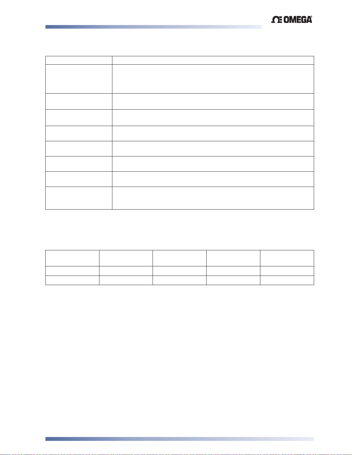
Limit Devices–CN2516, CN2508 and CN2504 Product Manual
Thermocouple Performance
Calibration:
Measurement
Accuracy:
Linearisation
Accuracy:
Cold Junction
Compensation:
Temperature
Stability:
Supply Voltage
Influence:
Relative Humidity
Influence:
Sensor Resistance
Influence:
Sensor Break
Protection:
Complies with BS4937, NBS125 and IEC584.
±0.1% of full range span ±1LSD.
NOTE: Reduced performance for B Thermocouple from 100 to 600°C.
NOTE: PtRh 20% vs PtRh 40% Thermocouple accuracy is 0.25% and has
reduced performance below 800°C.
Better than ±0.2°C any point, for 0.1° resolution ranges (±0.05°C typical).
Better than ±0.5°C any point, for 1° resolution ranges.
Better than ±0.7°C under reference conditions.
Better than ±1°C under operating conditions.
0.01% of span/°C change in ambient temperature.
Negligible.
Negligible.
Thermocouple 100Ω: <0.1% of span error.
Thermocouple 1000Ω: <0.5% of span error.
Break detected within two seconds. Limit outputs turn off (goes into
Exceed condition); Alarms operate as if the process variable is overrange.
Resistance Temperature Detector (RTD)
RTD Ranges Available
Range Min
in °C
-128.8 537.7 -199.9 999.9 0.1°
-199 800 -328 1472 1° (default)
Note:
Scale Range Upper Limit and Scale Range Lower Limit Configuration Mode parameters
can be used to restrict range.
Range Max
in °C
Range Min
in °F
Range Max
in °F
Resolution
Specifications Page 63
Page 72
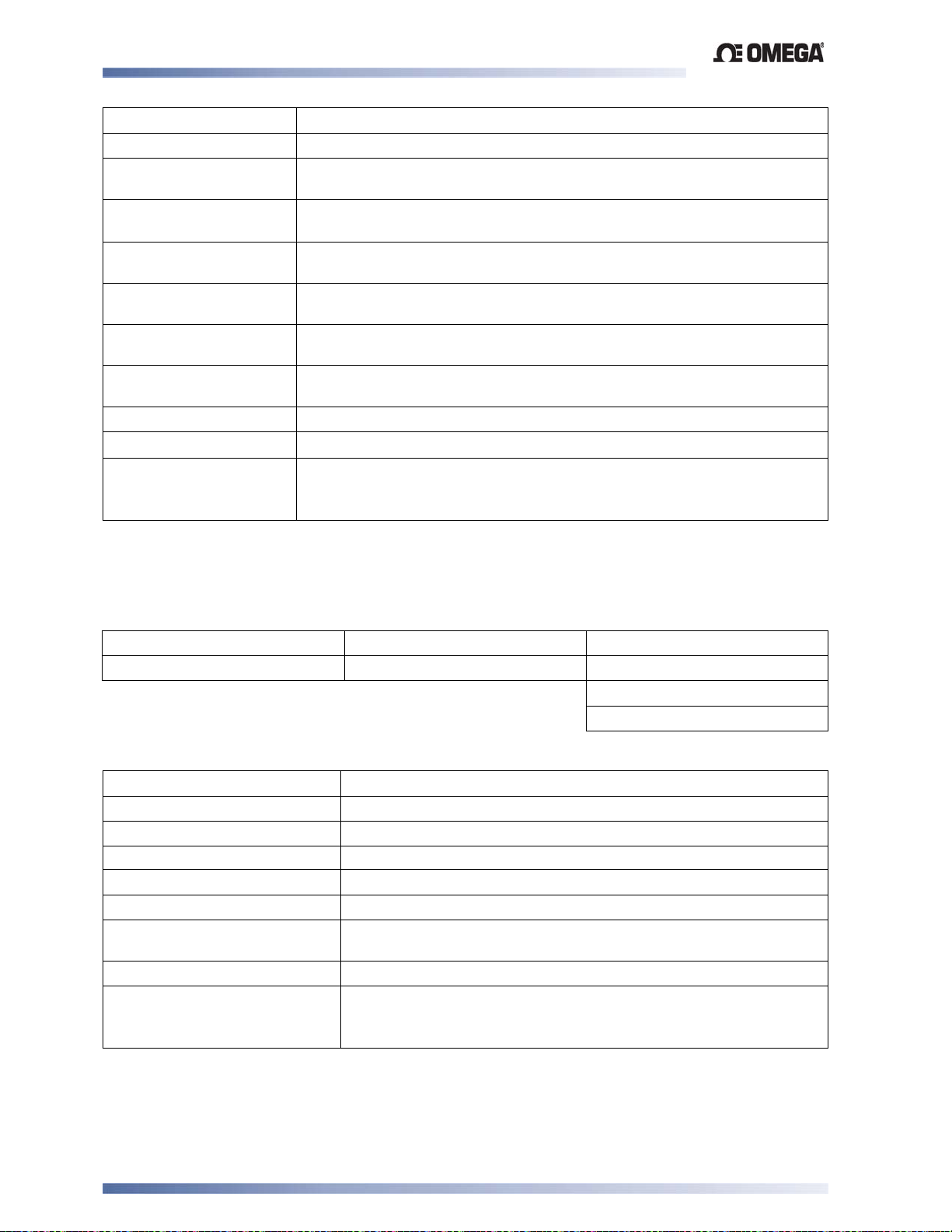
Limit Devices–CN2516, CN2508 and CN2504 Product Manual
y
RTD Performance
Type:
Calibration:
Measurement
Accuracy:
Linearisation
Accuracy:
Temperature
Stabilit
:
Supply Voltage
Influence:
Relative Humidity
Influence:
Sensor Resistance
Influence:
Lead Compensation:
RTD Sensor Current:
Sensor Break
Protection:
DC Linear
Three-wire Pt100.
Complies with BS1904 and DIN43760 (0.00385Ω/Ω/°C).
±0.1% of span ±1LSD.
Better than ±0.2°C any point, any 0.1°C range (±0.05°C typical). Better
than ±0.5°C any point, any 1°C range.
0.01% of span/°C change in ambient temperature.
Negligible.
Negligible.
Pt100 50Ω/lead: <0.5% of span error.
Automatic scheme.
150μA (approximately).
Break detected within two seconds. Limit outputs turn off (goes into
Exceed condition); Alarms operate as if the process variable has gone
over-range.
DC Linear Ranges Available
0 to 20mA 0 to 50mV 0 to 5V
4 to 20mA (default) 10 to 50mV 1 to 5V
0 to 10V
2 to 10V
DC Linear Performance
Scale Range Upper Limit:
Scale Range Lower Limit:
Minimum Span:
Measurement Accuracy:
Temperature stability:
Supply Voltage Influence:
Relative Humidity
–1999 to 9999. Decimal point as required.
–1999 to 9999. Decimal point as for Scale Range Upper Limit.
1 display LSD.
±0.1% of span ±1LSD.
0.01% of span/°C change in ambient temperature.
Negligible.
Negligible.
Influence:
Input Protection:
Sensor Break Protection:
Up to 10 times maximum span of selected input connection.
Applicable for 4 to 20mA, 1 to 5V and 2 to 10V ranges only.
Limit outputs turn off (goes into Exceed condition); Alarms operate
as if process variable is under-range.
Specifications Page 64
Page 73
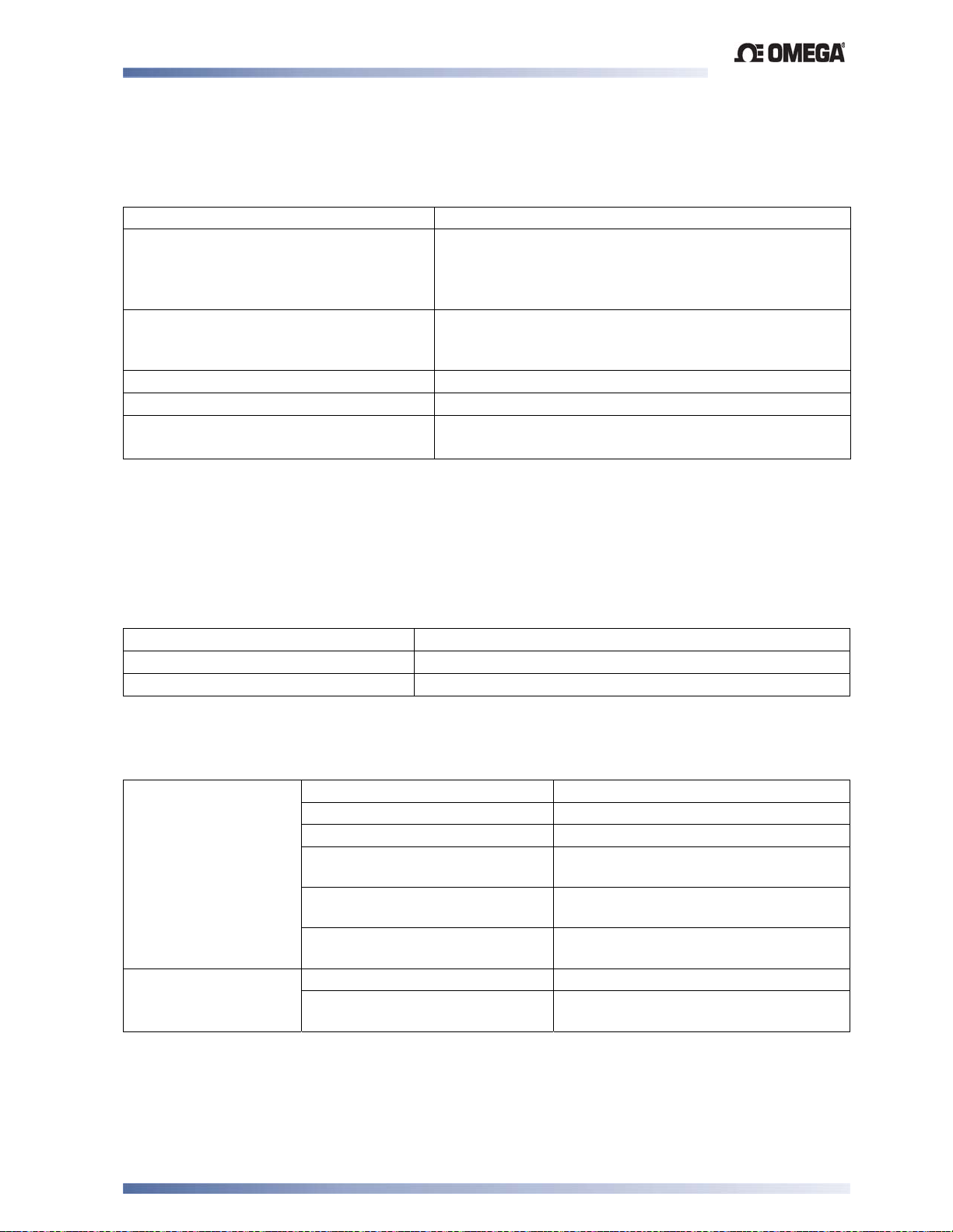
Limit Devices–CN2516, CN2508 and CN2504 Product Manual
Digital Inputs
Type:
Voltage-Free Operation:
TTL levels:
Maximum Input Delay (OFF-ON):
Maximum Input Delay (ON-OFF):
Isolation:
Output Specifications
Output Module Types
Option Slot 1 Module Options:
Option Slot 2 Module Options:
Option Slot 3 Module Options:
Voltage-free or TTL-compatible
Connection to contacts of external switch or relay:
Open = Minimum contact resistance = 5KΩ,
Closed = Latching Relay, reset (edge triggered).
Maximum contact resistance = 50Ω.
2.0 to 24VDC
–0.6 to 0.8VDC = Latching Relay, reset (edge
triggered)
0.25 second.
0.25 second.
Reinforced safety isolation from any source of
hazardous voltages.
Limit Controllers have a fixed Latching Relay only.
Relay, SSR drive, Triac or DC linear.
Relay, SSR drive, DC Linear or Transmitter PSU.
Specifications of Output Types
Single Relay:
SSR Driver:
Contact Type: Single pole double throw (SPDT).
OP1 Relay Contact Rating: 5A latching relay
OP2 / 3 Relay Contact Rating: 2A resistive at 240V AC
Alarm Lifetime: >500,000 operations at rated
Limit Output Lifetime: >100,000 operations at rated
Isolation: Basic Isolation from universal input
Drive Capability: 10V minimum at up to 20mA load.
Isolation: Not isolated from universal input or
voltage/current.
voltage/current.
and SSR outputs.
other SSR driver outputs.
Specifications Page 65
Page 74
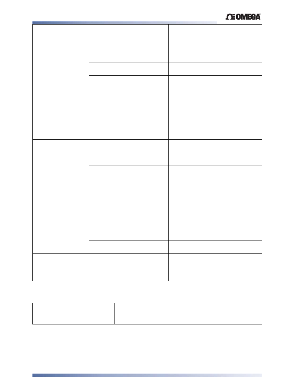
Limit Devices–CN2516, CN2508 and CN2504 Product Manual
Triac: Operating Voltage Range: 20 to 280Vrms @47 to 63Hz. (140V
max when directly driving motorised
valves).
Current Rating: 0.01 to 1A (full cycle rms on-state @
25°C); derates linearly above 40°C to
0.5A @ 80°C.
Linear DC:
Transmitter Power
Supply:
Max. Non-repetitive Surge
Current (16.6ms):
Min. OFF-State dv/dt @ Rated
Voltage:
Max. OFF-State leakage @
Rated Voltage:
Max. ON-State Voltage Drop @
Rated Current:
Repetitive Peak OFF-state
Voltage, Vdrm:
Isolation: Reinforced safety isolation from inputs
Resolution: Eight bits in 250mS
Update Rate:
Ranges:
Load Impedance:
Accuracy:
Isolation:
Power Rating
Isolation:
25A peak.
500V/μs.
1mA rms.
1.5V peak.
600V minimum.
and other outputs.
(10 bits in 1 second typical, >10 bits in
>1 second typical).
Every control algorithm execution.
0 to 10V
0 to 5V
2 to 10V
0 to 20mA & 4 to 20mA:
500Ω maximum.
0 to 5V, 0 to 10V & 2 to 10V:
500Ω minimum.
Short circuit protected.
±0.25% (mA @ 250Ω, V @ 2kΩ).
Degrades linearly to ±0.5% for
increasing burden (to specification
limits).
Reinforced safety isolation from inputs
and other outputs.
19 to 28VDC (24V nominal) into 910Ω
minimum resistance.
Reinforced safety isolation from inputs
and other outputs.
0 to 20mA
4 to 20mA
(default)
Control Specifications
Setpoint Range:
Setpoint Maximum:
Setpoint Minimum:
Specifications Page 66
Limited by Setpoint Upper Limit and Setpoint Lower Limit.
Limited by Setpoint and Scale Range Upper Limit.
Limited by Scale Range Lower Limit and Setpoint.
Page 75

Limit Devices–CN2516, CN2508 and CN2504 Product Manual
Process Alarms
Maximum Number of Alarms
Combinatorial Alarms:
Two “soft” process alarms (high, low, deviation or band)
Logical OR or AND of alarms to any suitable output.
Digital Communications
Type: Asynchronous Serial.
Protocols Supported:
Physical Layer:
Zone address range:
Bit rate:
Bits per character:
Stop bits:
Parity:
Isolation:
Modbus RTU (all models) and ASCII (some models).
RS485.
1 to 99 (ASCII), 1 to 255 (Modbus).
1200, 2400, 4800, 9600 and 19200 bps.
ASCII: 10
Modbus: 10 or 11 (depending on parity setting)
1
ASCII: Even (fixed).
Modbus: None, even or odd (selectable).
Reinforced safety isolation from inputs and outputs.
Reference Conditions
Ambient Temperature:
Relative Humidity: 60 to 70%.
Supply Voltage:
Source Resistance:
Lead Resistance:
20°C ±2°C.
100 to 240V AC 50Hz ±1%.
<10Ω for thermocouple input.
<0.1Ω/lead balanced (Pt100).
Operating Conditions
Ambient Temperature (operating):
Ambient Temperature (storage):
Relative Humidity:
Altitude:
Supply Voltage:
Power Consumption:
Source Resistance:
PT100 Input Lead Resistance:
0°C to 55°C.
-20°C to 80°C.
20% to 95% non-condensing.
Up to 2000m above sea level.
Either 100 to 240V ±10% AC 50/60Hz
or 20 to 48V AC 50/60Hz & 22 to 55V DC
5W / 7.5 VA maximum.
1000Ω maximum (thermocouple).
50Ω per lead maximum, balanced
Specifications Page 67
Page 76
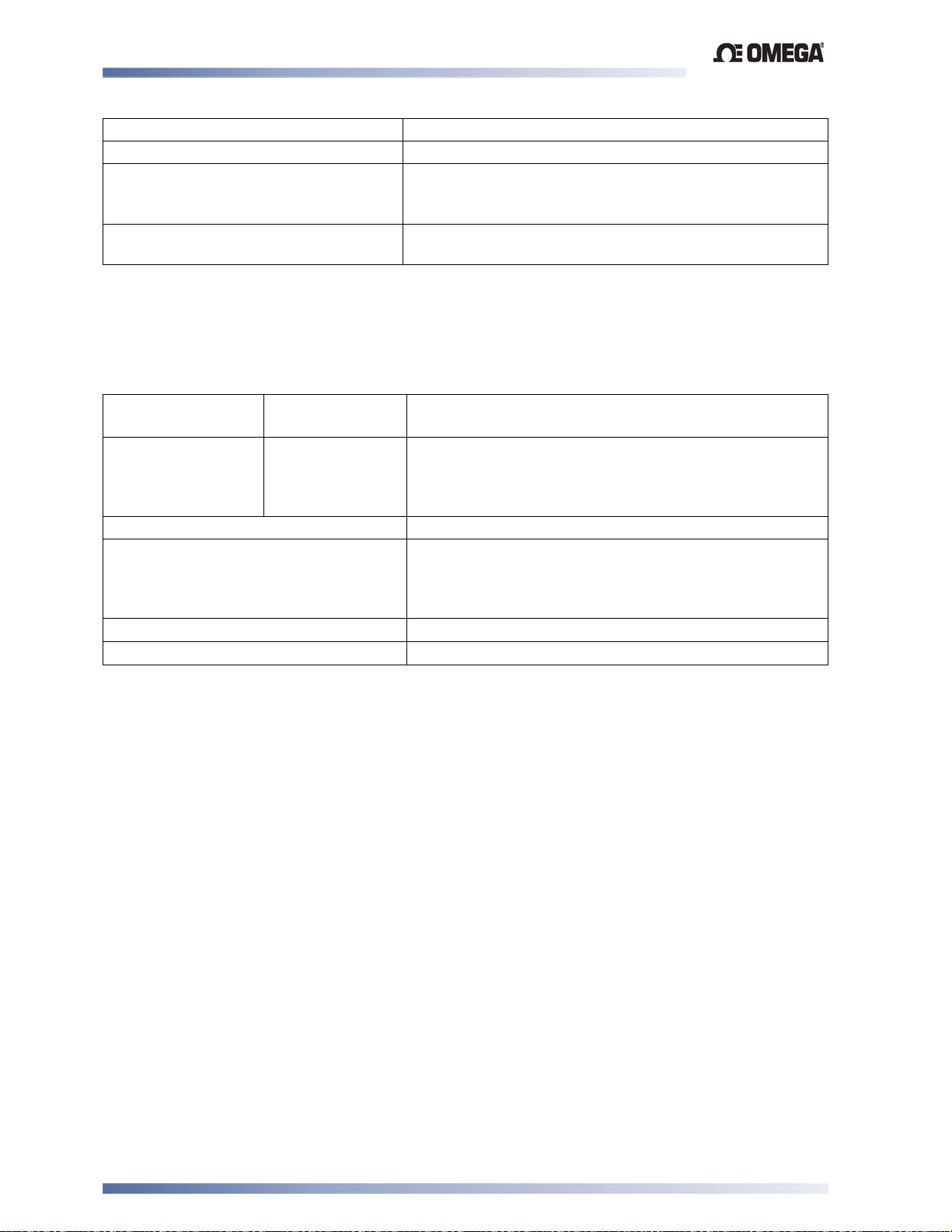
Limit Devices–CN2516, CN2508 and CN2504 Product Manual
Standards
Conformance Norms:
EMC standards:
Safety Standards:
Front Panel Sealing:
CE.
EN61326*
EN61010-1
Pollution Degree 2, Installation Category II.
FM 3545, 1998.
IP66 when correctly mounted – refer to installation
section
Note:
*For disturbances induced by RF fields of 10V/m 80% AM at 1kHz the input accura
specificati
on is changed to 0.25% in the frequency bands 465 to 575 MHz and 63
MHz.
Physical Specifications
Dimensions: Depth behind
panel:
Front bezel
size (w x h):
Mounting:
Panel cut-out size (w x h)::
110mm (1/16 DIN instruments).
100mm (
48 x 48mm (1/16 DIN instruments).
48 x 96mm (
96 x 48mm (
96 x 96mm (
Plug-in with panel mounting fixing strap.
45mm x 45mm (1/16 DIN instruments).
45 x 92mm (
1
/8 & 1/4 DIN instruments).
1
/8 DIN controllers).
1
/8 DIN indicators).
1
/4 DIN instruments).
1
/8 DIN controllers).
cy
0 to 660
Terminals:
Weight:
1
92mm x 92mm (
Screw type (combination head).
0.21kg maximum.
/4 DIN instruments).
Specifications Page 68
Page 77

WARRANTY/DISCLAIMER
OMEGA ENGINEERING, INC. warrants this unit to be free of defects in materials and workmanship for a
period of 13 months from date of purchase. OMEGA’s WARRANTY adds an additional one (1) month
grace period to the normal one (1) year product warranty to cover handling and shipping time. This
ensures that OMEGA’s customers receive maximum coverage on each product.
If the unit malfunctions, it must be returned to the factory for evaluation. OMEGA’s Customer Service
Department will issue an Authorized Return (AR) number immediately upon phone or written request.
Upon examination by OMEGA, if the unit is found to be defective, it will be repaired or replaced at no
charge. OMEGA’s WARRANTY does not apply to defects resulting from any action of the purchaser,
including but not limited to mishandling, improper interfacing, operation outside of design limits,
improper repair, or unauthorized modification. This WARRANTY is VOID if the unit shows evidence of
having been tampered with or shows evidence of having been damaged as a result of excessive corrosion;
or current, heat, moisture or vibration; improper specification; misapplication; misuse or other operating
conditions outside of OMEGA’s control. Components in which wear is not warranted, include but are not
limited to contact points, fuses, and triacs.
OMEGA is pleased to offer suggestions on the use of its various products. However,
OMEGA neither assumes responsibility for any omissions or errors nor assumes liability for
any damages that result from the use of its products in accordance with information provided
by OMEGA, either verbal or written. OMEGA warrants only that the parts manufactured
by it will be as specified and free of defects. OMEGA MAKES NO OTHER WARRANTIES OR
REPRESENTATIONS OF ANY KIND WHATSOEVER, EXPRESS OR IMPLIED, EXCEPT
THAT OF TITLE, AND ALL IMPLIED WARRANTIES INCLUDING ANY WARRANTY OF
MERCHANTABILITY AND FITNESS FOR A PARTICULAR PURPOSE ARE HEREBY
DISCLAIMED. LIMITATION OF LIABILITY: The remedies of purchaser set forth herein are
exclusive, and the total liability of OMEGA with respect to this order, whether
based on contract, warranty, negligence, indemnification, strict liability or otherwise,
shall not exceed the purchase price of the component upon which liability
is based. In no event shall OMEGA be liable for consequential, incidental or special damages.
CONDITIONS: Equipment sold by OMEGA is not intended to be used, nor shall it be used: (1) as a “Basic
Component” under 10 CFR 21 (NRC), used in or with any nuclear installation or activity; or (2) in medical
applications or used on humans. Should any Product(s) be used in or with any nuclear installation or
activity, medical application, used on humans, or misused in any way, OMEGA assumes no responsibility
as set forth in our basic WARRANTY / DISCLAIMER language, and, additionally, purchaser will indemnify
OMEGA and hold OMEGA harmless from any liability or damage whatsoever arising out of the use of the
Product(s) in such a manner.
RETURN REQUESTS/INQUIRIES
Direct all warranty and repair requests/inquiries to the OMEGA Customer Service Department.
BEFORE RETURNING ANY PRODUCT(S) TO OMEGA, PURCHASER MUST OBTAIN AN AUTHORIZED
RETURN (AR) NUMBER FROM OMEGA’S CUSTOMER SERVICE DEPARTMENT (IN ORDER TO AVOID
PROCESSING DELAYS). The assigned AR number should then be marked on the outside of the return
package and on any correspondence.
The purchaser is responsible for shipping charges, freight, insurance and proper packaging to prevent
breakage in transit.
FOR WARRANTY RETURNS, please have the
following information available BEFORE
contacting OMEGA:
1. Purchase Order number under which the product
was PURCHASED,
2. Model and serial number of the product under
warranty, and
3. Repair instructions and/or specific problems
relative to the product.
OMEGA’s policy is to make running changes, not model changes, whenever an improvement is possible. This affords
our customers the latest in technology and engineering.
OMEGA is a trademark of OMEGA ENGINEERING, INC.
© Copyright 2018 OMEGA ENGINEERING, INC. All rights reserved. This document may not be copied, photocopied,
reproduced, translated, or reduced to any electronic medium or machine-readable form, in whole or in part, without the
prior written consent of OMEGA ENGINEERING, INC.
FOR NON-WARRANTY REPAIRS,
for current repair charges. Have the following
information available BEFORE contacting OMEGA:
1. Purchase Order number to cover the COST
of the repair,
2. Model and serial number of the product, and
3. Repair instructions and/or specific problems
relative to the product.
consult OMEGA
Page 78

Where Do I Find Everything I Need for
Process Measurement and Control?
OMEGA…Of Course!
Shop online at omega.com
TEMPERATURE
MU
Thermocouple, RTD & Thermistor Probes, Connectors, Panels & Assemblies
MU
Wire: Thermocouple, RTD & Thermistor
MU
Calibrators & Ice Point References
MU
Recorders, Controllers & Process Monitors
MU
Infrared Pyrometers
PRESSURE, STRAIN AND FORCE
MU
Transducers & Strain Gages
MU
Load Cells & Pressure Gages
MU
Displacement Transducers
MU
Instrumentation & Accessories
FLOW/LEVEL
MU
Rotameters, Gas Mass Flowmeters & Flow Computers
MU
Air Velocity Indicators
MU
Turbine/Paddlewheel Systems
MU
Totalizers & Batch Controllers
pH/CONDUCTIVITY
MU
pH Electrodes, Testers & Accessories
MU
Benchtop/Laboratory Meters
MU
Controllers, Calibrators, Simulators & Pumps
MU
Industrial pH & Conductivity Equipment
DATA ACQUISITION
MU
Data Acquisition & Engineering Software
MU
Communications-Based Acquisition Systems
MU
Plug-in Cards for Apple, IBM & Compatibles
MU
Data Logging Systems
MU
Recorders, Printers & Plotters
HEATERS
MU
Heating Cable
MU
Cartridge & Strip Heaters
MU
Immersion & Band Heaters
MU
Flexible Heaters
MU
Laboratory Heaters
ENVIRONMENTAL
MONITORING AND CONTROL
MU
Metering & Control Instrumentation
MU
Refractometers
MU
Pumps & Tubing
MU
Air, Soil & Water Monitors
MU
Industrial Water & Wastewater Treatment
MU
pH, Conductivity & Dissolved Oxygen Instruments
M5284/0518
 Loading...