

Page 1
®
User’s Guide
Shop online at
omega.com
e-mail: [email protected]
For latest product manuals:
www.omegamanual.info
sm
CN243 SERIES
Controllers
Page 2

omega.com [email protected]
Servicing North America:
U.S.A.: Omega Engineering, Inc., One Omega Drive, P.O. Box 4047
Stamford, CT 06907-0047 USA
Toll-Free: 1-800-826-6342 (USA & Canada only)
Customer Service: 1-800-622-2378 (USA & Canada only)
Engineering Service: 1-800-872-9436 (USA & Canada only)
Tel: (203) 359-1660 Fax: (203) 359-7700
e-mail: [email protected]
For Other Locations Visit
omega.com/worldwide
The information contained in this document is believed to be correct, but OMEGA accepts no
liability for any errors it contains, and reserves the right to alter specifications without notice.
Page 3

Table of contents
1 Safety guide lines ......................................................................................................................................5
2 Model ide ntification .................................................................................................................................5
3 Technical Data ...........................................................................................................................................5
3.1 Genera l data .....................................................................................................................................5
3.2 Hardware data .................................................................................................................................6
3.3 Software d ata ...................................................................................................................................6
4 Dimensions a nd Installation ..................................................................................................................7
4.1 Panel Assembly ................................................................................................................................ 8
4.2 Electronics R emoval ........................................................................................................................8
5 Electrical w irings .......................................................................................................................................9
5.1 Wiring diagram ................................................................................................................................ 9
6 Display and Ke y Functions .................................................................................................................... 15
6.1 Numeric Indica tors (Display) ......................................................................................................15
6.2 Meaning of Status Light s (Led)...................................................................................................15
6.3 Keys .................................................................................................................................................... 16
7 Controller Func tions ...............................................................................................................................16
7.1 Mo difying Main Setp oint and Alarm Setpoint Values ......................................................... 16
7.2 Auto-Tuning ....................................................................................................................................16
7.3 M anual Tuning ...............................................................................................................................16
7.4 Automatic Tuning ..........................................................................................................................17
7.5 S o f t -S t a r t ..........................................................................................................................................17
7.6 Automatic / Manua l Regulation for % Output Cont rol .......................................................17
7.7 Pre-Programmed Cycle ................................................................................................................18
7.8 CN- Config-Module (optional) ....................................................................................................19
7.9 Latch- on function......................................................................................................................... 20
7.10 Loo p Break Alarm On Current Trasformer ............................................................................. 20
7.11 Di gital Input Functions ............................................................................................................... 22
7.12 Dual Action Heating- Cooling ................................................................................................... 23
8 Serial Commu nication ...........................................................................................................................24
9 Enter configuratio n ................................................................................................................................ 29
9.1 Loading default va lues................................................................................................................ 29
10 Table of Configura tion Parameters ................................................................................................... 30
11 Alarm I ntervention Modes ....................................................................................................................42
12 Table of Anomaly Signals ......................................................................................................................45
13 Configura tion EASY-UP ........................................................................................................................ 46
ATR243 - User manual - 3
Page 4

Sommario
1 Norme di sicur ezza .................................................................................................................................52
2 Identificazione del modello ..................................................................................................................52
3 Dati tecnici ................................................................................................................................................53
3.1 Caratteristiche g enerali ...............................................................................................................53
3.2 Caratteristiche Hardware ............................................................................................................53
3.3 Caratteristiche S oftware............................................................................................................. 54
4 Dimension i ed installazione ................................................................................................................ 54
4.1 Montaggio a pannello .................................................................................................................55
4.2 Estrazion e dell’elettronica ..........................................................................................................55
5 Collegamenti elettrici............................................................................................................................ 56
5.1 Schema di collegamento ............................................................................................................ 56
6 Funzione dei vi sualizzatori e tasti ...................................................................................................... 62
6.1 Indicatori nume rici (Display) .................................................................................................... 62
6.2 Significato delle spi e di stato (Led) .......................................................................................... 62
6. 3 Ta sti ...................................................................................................................................................63
7 Funzioni del regolatore..........................................................................................................................63
7.1 Mo difica valore setpoint prin cipale e setpoint di allar me ..................................................63
7.2 Auto-Tuning ....................................................................................................................................63
7.3 Lancio del Tuning Manuale ........................................................................................................63
7.4 Lancio del Tuning Automati co ..................................................................................................64
7.5 S o f t -S t a r t ......................................................................................................................................... 64
7.6 Regolazion e automatico / manuale per contro llo % uscita ............................................. 64
7.7 Ciclo pre-pr ogrammato ...............................................................................................................65
7.8 CN- Config-Module (opzionale) ................................................................................................ 66
7.9 Funzione Latch on .........................................................................................................................67
7.10 Loo p Break Alarm da ingresso T.A . (Trasformatore Amp.) ................................................ 68
7.11 Funzioni da Ingresso digitale .................................................................................................... 68
7.12 Funzio namento in doppia azio ne (caldo / freddo) ..............................................................69
8 Comunicazio ne Seriale ..........................................................................................................................71
9 Accesso alla configu razione .................................................................................................................75
9.1 Caricamento valori d i default ....................................................................................................75
10 Tabella param etri di configurazione .................................................................................................76
11 Modi d ’intervento allarme ................................................................................................................... 89
12 Tabella segnalazioni anomalie ...........................................................................................................92
13 Configurazione EASY-UP .......................................................................................................................92
4 - ATR243 - Manuale d’uso
Page 5

Introduction
Thank you for choosing a Omega controller.
With CN243 model Omega integrates in a single device all options for sensor reading and
actuators command, beside ex tended supply range 24…230 Vac/Vdc. With 18 selectable
sensors and outputs configurable as relay, SSR command, 4…20 mA and 0…10 Volt the
user or retailer can reduce stock needs.
The series includes also a model with serial communication RS485 Modbus RTU and with
a loading control function via current transformer. The possibility to repeat parametrization is simplified by the CN-Config-Module with internal battery that do not require
power supply for the controller.
1 Safety guide lines
Read carefully the safety guidelines and programming instructions contained in this
manual before using/connecting the device.
Disconnect power supply before proceeding to hardware set tings or electrical wirings.
Only qualified personnel should be allowed to use the device and/or service it and in
accordance to technical data and environmental conditions listed in this manual.
Do not dispose electric tools together with household waste material. In observance
European Directive 2002/96/EC on waste electrical and electronic equipment and its
implementation in accordance with national law, electric tools that have reached the end
of their life must be collected separately and returned to an environmentally compatible
recycling facility.
2 Model identification
CN243 series includes three versions. Lo oking at the table here below it is possible to find
the required model.
Power supply 24…230 Vac/Vdc +/-15% 50/60 Hz – 5,5 VA
CN243- R1F2 2 relays 5 A or 1 relay + 1 Ssr/V/mA
CN243-R1R2F3 2 relays 5 A + 1 Ssr/V/mA + RS4 85 + current transformer*
CN243R1R2 R3F4C4
* Models with c urrent transforme r input for “Loop B reak Alarm” func tion.
3 relays 5 A + 1 Ssr/V/mA + current transformer*
3 Technical Data
3.1 General data
Indicators
Operating
temperature
Sealing
Material PC ABS UL94VO self-extinguishing
Weight 165 g (-20ABC) / 185 g (-21/31ABC)
4x0.40 inch displays
4x0.30 inch displays
Temperature 0-45 °C
Humidity 35..95 uR%
IP65 front panel (with gasket)
IP20 box and terminals
ATR243 - User manual - 5
Page 6

3.2 Hardware data
Power supply
Analogue
imput
Relay
output
SSR /V/mA
output
Extended range 24..230 Vac/Vdc
±15% 50/60 Hz
1: AN1 configurable via software.
Input: Thermocouple type K, S, R ,
J. Automatic compensation of cold
junction from 0°C to 50°C.
Thermoresistance:
PT100, PT500, P T1000, Ni100,
PTC1K, NTC10K (β 3435K, OMEGA),
NTC2252-OMEGA . Linear: 0-10 V,
0-20 or 4-20 mA, 0 -40 mV.
Current transformer: 50 mA, 1024
points on version CN243-R1R2F3/
R1R2 R3F4C4. Potentiometers: 6
KΩ, 150 KΩ.
2 Relays (CN243-R1F2/ R1R2F3).
3 Relays (CN243-R1R2R 3F4C4).
Configurable as command and / or
alarm output.
1 SSR Linear 0/4…20mA or
0. .10 Vol t.
Deselecting OUT2 relay on
CN243-R1F2. Configurable as
command output or retransmission of setpoint or process.
Consumption: 5.5 VA.
Tolerance (25 °C) +/-0.2% ±1 digit
for thermocouple input, thermo
resistance and V / mA.
Cold junction accuracy 0.1 °C/°C.
Impedance:
0-1 0 V: Ri>110 KΩ
0-20 mA: Ri<5 Ω
4-2 0 mA: Ri<5 Ω
0- 40 mV: Ri>1 MΩ
Contacts
5 A - 250 V~.
Resistive load.
12V / 30mA (min. 10.5 V DC).
Configurable:
0-1 0 V with 9500 points +/-0. 2%
(F.s.)
0-2 0 mA with 7500 points +/-0.2%
(F.s.)
4-2 0 mA with 6000 points +/-0.2%
(F.s.)
3.3 Software data
Regulation
algorithms
Proportional
band
Integral time 0,0...999,9 sec. (0 excludes integral function)
Derivative time 0,0...999,9 sec. (0 excludes derivative function)
Controller
functions
ON - OFF with hysteresis.
P, P.I., P.I.D., P.D. with propor tional time.
0...9999 °C or °F
Manual or automatic Tuning, configurable alarms, protection of
command and alarm setpoints, activation of functions via digital
input, preset cycle with Start / Stop.
6 - ATR243 - User manual
Page 7
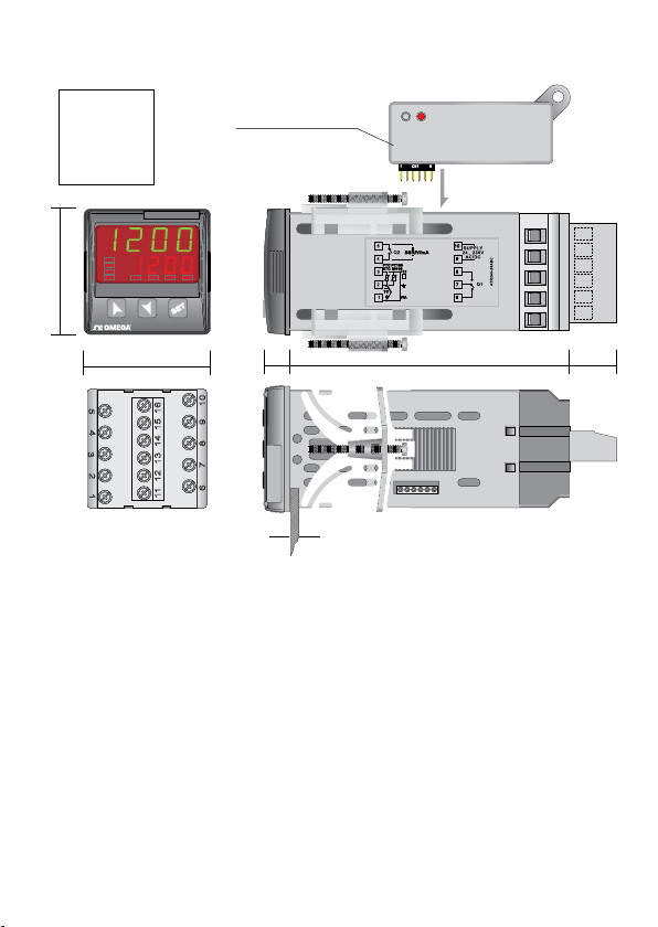
4 Dimensions and Installation
15
1116
234
12131415
1 6
12
3
4
5
11 13 14 15 1612
6 7 8 9 10
CN1
1 6
DIMA DI
FORATURA
FRONTAL PANEL
CUT-OUT
46 X 46 mm
48 mm
48 mm 106.5 mm10.5 18
Suggested thickness / Spessore suggerito 2 ÷ 6 mm
CN-CONFIG-MODULE
(optional)
CN-CONFIG-MODULE
CN243
ATR243 - User manual - 7
Page 8
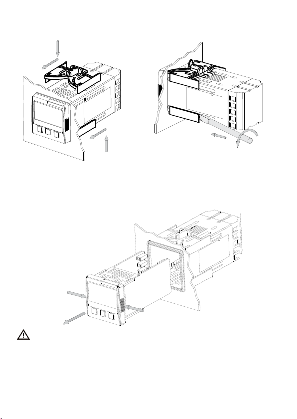
4.1 Panel Assembly
1
2
2
1
Method of panel assembly and fi xing of
anchorage hooks.
To dismantle, use a screwdriver and
slightly force the fi xing hooks to remove
them from the fi xing guide.
1
4.2 Electronics Removal
To remove the electronics, grip the front part using the two specifi c side ridges.
1
1
2
Disconnect the device from the mains before starting to confi gurate or service it.
8 - ATR243 - User manual
2
Page 9
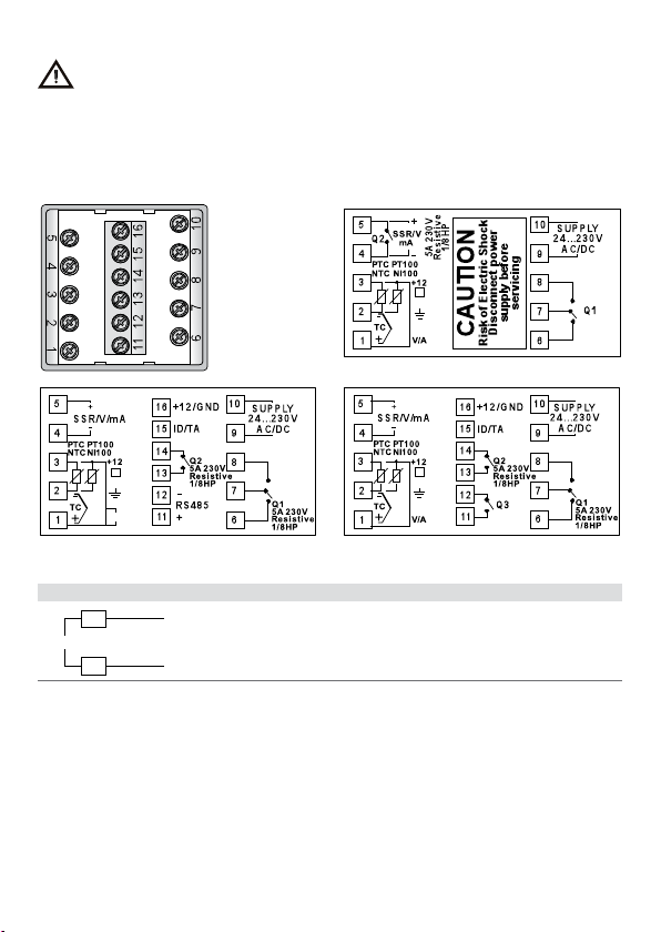
5 Electrical wirings
SUPPLY
9
Although this controller has been designed to resist noises in an industrial
environment, please notice the following safety guidelines:
• Separate control lines from the power wires.
• Avoid the proximity of remote control switches, electromagnetic meters, powerful
engines.
• Avoid the proximity of power groups, especially those with phase control.
5.1 Wiring diagram
CN243-R1F2
V/I
CN243-R1R2F3 CN243-R1R2R3F4C4
5.1. a Power
10
24...230V
AC/DC
Switching po wer supply with ext ended range 24…230 Vac/
dc ±15% 50/60 Hz – 5,5 VA (with galvanic isolation).
ATR243 - User manual - 9
Page 10
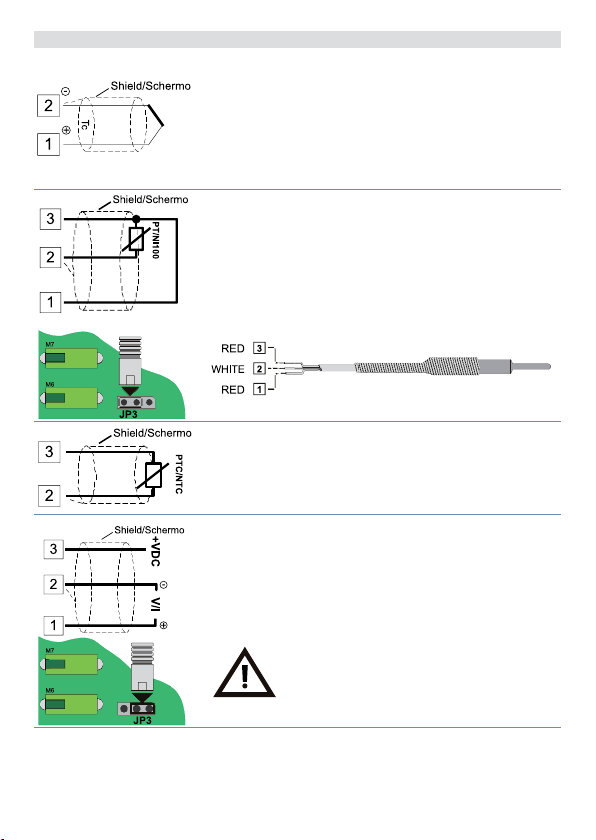
5.1. b AN1 Analogue Input
For thermocouples K, S, R, J.
• Comply with polarity.
• For possible extensions, use a compensated wire
• When shielded cable is used, it should be grounded at
and terminals suitable for the thermocouples used
(comp ensated ).
one side only.
Rosso
Red
Bianco
White
Rosso
Red
For thermoresistances PT100, NI100.
• For the three-wire connection use wires with the same
section.
• For the two-wire connection short-circuit terminals 1
and 3.
• When shielded cable is used, it should be grounded at
one side only.
• Select internal jumper JP3 as in the fi gure.
For thermoresistances NTC, PTC, PT500, PT1000 e potentiometers.
When shielded cable is used, it should be grounded at one
side only to avoid ground loop currents.
For linear signals V / mA .
• Comply with polarity.
• When shielded cable is used, it should be grounded at
one side only.
• Select internal jumper JP3 as in the fi gure.
If jumpers are not properly selected, 12 Vdc /
30 mA are not available on terminal 3 to
power the sensor.
10 - ATR243 - User manual
Page 11
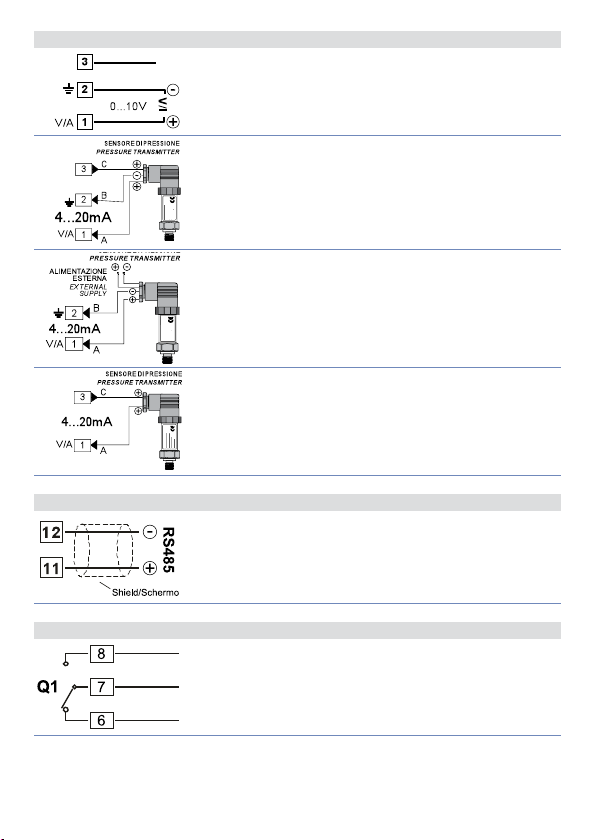
5.1. c Example of Connection for linear input Volt and mA
+12 V
30 mA
For signals 0….10 V.
Comply with polarity.
+12 V
30 mA
For signals 0/4….20 mA with three-wire sensor.
Comply with polarity:
A= Sensor output
B= Sensor ground
C= Sensor power (+12Vdc / 30mA)
For signals 0/4….20 mA with external power of sensor.
Comply with polarity:
A= Sensor output
B= Sensor ground
+12 V
30 mA
For signals 0/4….20 mA with two-wire sensor.
Comply with polarity:
A= Sensor output
C= Sensor power supply (+12Vdc / 30mA)
5.1. d Serial Input (only CN243-R1R2F3)
RS485 Modbus RTU communication.
5.1. e Relay Q1 Output
Capacity 5 A / 250 V~ for resistive loads.
NB: see graphic next page.
ATR243 - User manual - 11
Page 12
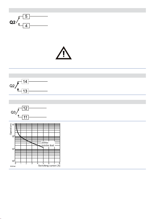
5.1. f Relay Q2 output for CN243-R1F2
Capacity 5 A / 250 V~ for resistive loads.
To select Q2 as relay output, verify that jumpers JP5 and
JP7 are not inserted.
NB: see graphic next page.
Connecting a load without removing the
jumpers will permanently damage the
controller.
5.1. g Relay Q2 output for CN243-R1R2F3 and CN243-R1R2R3F4C4
Capacity 5 A / 250 V~ for resistive loads.
NB: see graphic.
5.1. h Relay Q3 output for CN243-R1R2R3F4C4
Q3 Relay Output on CN243-R1R2R3F4C4.
NB: see graphic.
12 - ATR243 - User manual
Electrical endurance Q1 / Q2 / Q3:
5 A, 250 Vac, resistive loads, 10
20/2 A, 250 Vac, cosφ = 0.3, 10
5
operations.
5
operations.
Page 13
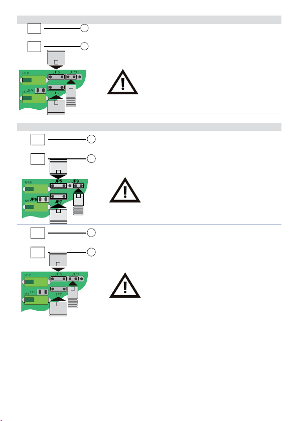
5.1. i SSR output
5
SSR /V/mA
4
+
-
5.1. j mA / Volt output
5
+
SSR /V/mA
4
-
SSR command output 12 V / 30 mA (min. 10.5 V DC).
Insert JP5 and JP7 and select JP9 as in the
fi gure to use the SSR output.
Linear output in mA confi gurable using parameters
as command (parameter
process-setpoint (parameter
Insert JP5 and JP7 and select JP9 as in
fi gure to use the output in mA (Jumpers
supplied inside packaging).
) or retransmission of
c.out
).
rE t r.
5
SSR /V/mA
4
+
Linear output in Volt confi gurable using parameters
as command (parameter
-
process-setpoint (parameter
Insert JP5 and JP7 and select JP9 as in
fi gure to use the linear output in Volt
(Jumpers supplied inside packaging).
) or retransmission of
c.out
).
rE t r.
ATR243 - User manual - 13
Page 14
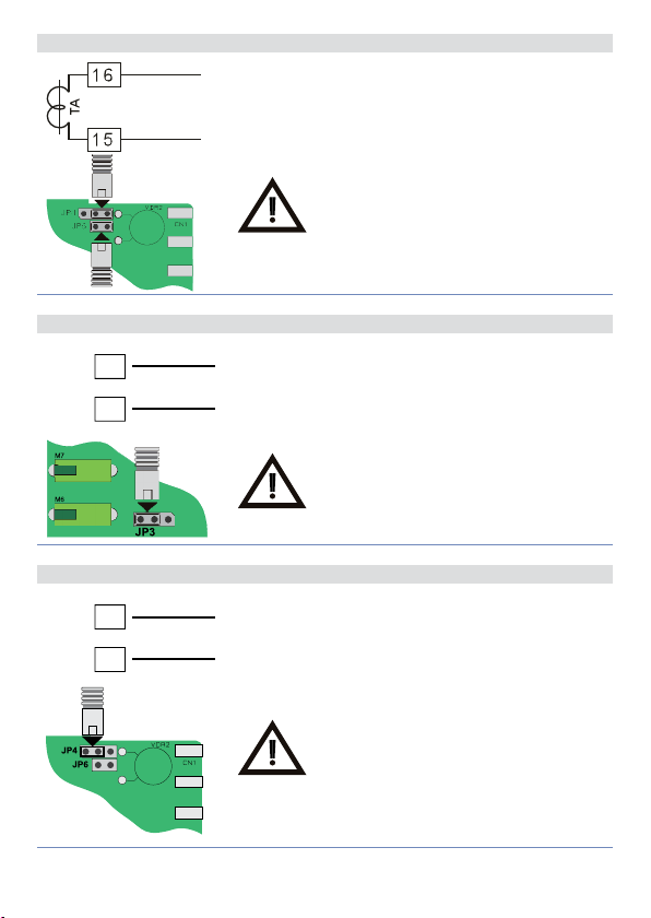
5.1. k Current Transformer Input on CN243-R1R2F3 and CN243-R1R2R3F4C4
• Input 50 mA for current transformer.
• Sampling time 80 ms.
• Confi gurable by parameters.
Insert JP4 and JP6 as in fi gure to select the
amperometric transformer input.
5.1. l Digital Input on CN243-R1F2
+ 12V
3
GND
I D
2
Digital input using parameter
The use of digital input in this version is possible only
with TC sensors, 0…10 V, 0/4…20 mA and 0…40 mV.
Select internal jumper JP3 as in fi gure.
d G ti
.
5.1. m Digital Input on CN243-R1R2F3 and CN243-R1R2R3F4C4
+ 12V
16
GND
I D
15
Digital input using parameter
d G ti
.
14 - ATR243 - User manual
Insert JP4 as in fi gure to selec t the digital
input.
Page 15
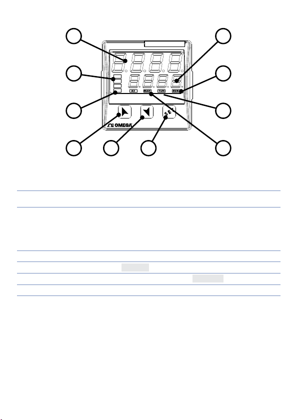
6 Display and Key Functions
1
CN243
2
3
4
8 9
C1
C2
A1
A2
10
7
6
5
6.1 Numeric Indicators (Display)
1
2
1234
1234
Normally displays the process. During the configuration phase, it
displays the parameter being inserted.
Normally displays the setpoint. During the configuration phase, it
displays the parameter value being inserted.
6.2 Meaning of Status Lights (Led)
3 C1 C2
4 A1 A2 A3 ON when the corresponding alarm is on.
5 MAN
6 TUN
7 REM ON when the controller communicates via serial por t.
ON when the output command is on.
C1 with relay/SSR/mA /Volt command or C1 (open) and C2
(close) for a motorised valve command.
ON when the “Manual ” function is on.
ON when the controller is running an “Autotune” cycle.
ATR243 - User manual - 15
Page 16
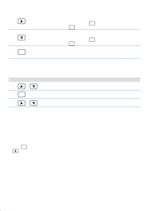
6.3 Keys
• Allows to increase the main setpoint.
8
9
SET
10
• During the configuration phase, allows to slide through
parameters. Together with the
• Pressed after the
• Allows to decrease the main setpoint.
• During the configuration phase, allows to slide through
parameters. Together with the
• Press ed after the
• Allows to display the alarm setpoint and runs the autotuning
function.
• Allows to vary the configuration parameters.
SET
key it allows to increase the alarm setpoint.
SET
key it allows to de crease the alarm setp oint.
SET
key it modifies them.
SET
key it modifies them.
7 Controller Functions
7.1 Modifying Main Setpoint and Alarm Setpoint Values
The setpoint value can be changed by keyboard as follows:
Press Display Do
1
2
3
or
SET
or
Value on display 2 changes.
Visualize alarm setpoint on
display 1 value being inserted.
Value on display 2 changes.
Increases or decreases the main
setpoint.
Increases or decreases the alarm
setpoint value.
7. 2 Auto-Tuning
Tuning procedure calculates the controller parameters and can be manual or automatic
according to selection on parameter 57 (
tunE
).
7. 3 Manual Tuning
Manual procedure allows the user greater flexibility to decide when to update P.I.D.
algorithm work parameters. The procedure can be ac tivated in two ways.
• Running Tuning by keyboard:
SET
Press
TUN led switches on and the procedure begins.
• Running Tuning by digital input:
Select
key until display 1 shows the writing
, display 2 shows on.
on parame ter 61
tun e
front panel) TUN led switches on and at second activation switches off.
At first act ivation of digital i nput (commutation on
d G t.i .
with display 2 showing
tunE
off
, press
16 - ATR243 - User manual
Page 17

7.4 Automatic Tuning
Automatic tuning activates when the controller is switched on or when the setpoint is
modified to a value over 35%.
To avoid an overshoot, the treshold where the controller calculates new P.I.D. parameters
is determined by the setpoint value minus the “Set Deviation Tune” (see parameter 58
).
S.D. t u .
SET
To exit Tuning and keep P.I.D. values unchanged, press
writing
and procedure finishes.
and display 2 sh ows on. Press , display 2 sho ws
tun e
key until display 1 shows the
.
TUN
led switch es off
off
7. 5 Soft-Start
To reach the setpoint the controller can follow a gradient expressed in units (example:
Degree/Hours).
Enter the gradient on parameter 62
activation the controller uses Soft-Start function.
If parameter 59
switch-on and elapsing of the time set on parameter 63, setpoint does not follow the
gradient anymore, but it reaches final setpoint with maximum power.
Autotuning does not work when only the par.
is different from 0 and parameter 57
m a . ti .
when Sof t-Start time is finished, while if parameter 57
can be started only when Sof t-Start finishes.
op.mo.
is set on
with chosen Units/Hours; only on subsequent
GrAd .
and parameter 63
co nt.
is different from 0. If parameter 63
GrAd .
is set on
tun e
tun e
is different from 0, after
m a . ti .
the autotuning starts
Auto
is set on
the autotuning
Man.
7.6 Automatic / Manual Regulation for % Output Control
This function allows to select automatic functioning or manual command of the output
percentage.
With parameter 60
1 First selection (
Pressing
Pressing
2 Second selection (
enables the same functioning, but with two important variants:
• If there is a temporary power failure or after switch-off, the manual functioning as well
• If the sensor breaks during automatic functioning, the controller moves to manual
SET
key display 1 shows
key display show s
using
Auto
as the previous output percentage value will be maintained at restarting.
mode while maintaining the output percentage command unchanged as generated
by the P.I.D. immediately before breakage.
and . To return to automatic mode, using the same procedure, select
on display 2: led MAN switches off and functioning returns to automatic mode.
the operator can select two methods:
Au.m a.
)
en.
EN. ST,
)
, while display 2 shows
p.---
; it is now possib le to change the out put percentag e
Man.
Auto
.
ATR243 - User manual - 17
Page 18
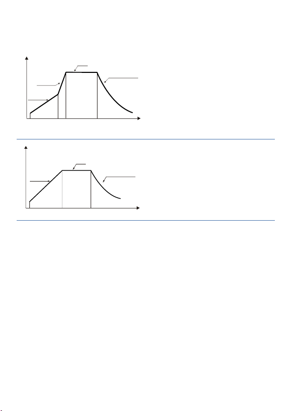
7.7 Pre-Programmed Cycle
Time
Setpoint
Time
The pre-programmed cycle function activates by setting
.
oP.Mo
First selection (
the controller reaches setpoint1 basing on
the gradie nt set on parame ter 62
it reaches ma ximum power up to setpo int 2.
When the pro cess reaches maximu m power,
this setpoint is maintained for the time set
on parameter 63
On expiry, the command output is disabled
and controller displays
at each activation of the controller, or via
digital input if it is enabled for this type of
functioning (see parameter 61
Second selection (
start-up is decided only on activation of the
digital input, according to the setting of
parameter 61
reaches setpoint 1 following gradient set in
parameter 62
When the process reaches this gradient, it
is maintained for the time set on parameter
On expiry, command output is
63
m a . ti .
disabled and the controller displays
Setpoint
Gradient
Gradient
Setpoint 2
Max.
power
Setpoint 1
Setpoint 1
Hold
Natural cooling
Hold
Natural cooling
or
Pr. cy
Pr. cy
on parameter 59
Pc. SS.
):
m a . ti .
stop
):
Pr. cy
On start-up, controller
d G t.i .
Gra d .
, then
Gra d .
. Cycle starts
).
d G t.i .
.
stop
Variation (
Selecting
) but with two important variations. If at starting the process is lower than SET1, the
cy
device regulates the output power according to the percentage selected on parameter
62
GrAd
When the process is greater than SET1 or the time selected on parameter 63
):
S.S. cY.
(Soft Start Cycle) the controller will operate as per the fi rst selection (
S.S. cY.
.
is elapsed, it reaches maximum power up to SET2. When the process reaches SET2 the
controller keeps it to infi nity.
If parame ter 59
: SET1 is no longer displayed and SET2 label becomes SET.
c. S.P.
Starting the manual tune during the regulation on SET1, TUN led switches ON only when
is confi gured as
oP.Mo.
it is possibl e to select
S.S. cY.
on parameter 17
Hi d E
the regulation switches to SET2.
The autotuning (manual or automatic) works only if SET2 is being regulated. If the
autotuning is launched during regulation on SET1 it doesn’t start until the regulation
switches to SE T2.
18 - ATR243 - User manual
M A . ti .
Pr.
Page 19
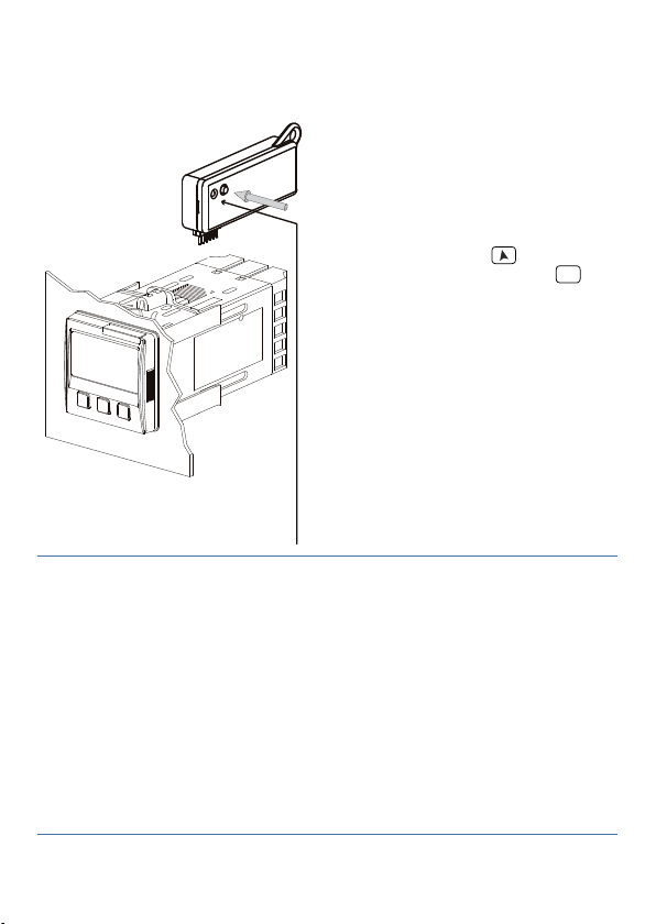
7.8 CN-Config-Module (optional)
Parameters and setpoint values can be duplicated from one controller to another using
the CN-Config-Module.
2 modes are available:
• With the controller connected to the
power supply.
Insert CN-Config-Module when the
controller is off.
On activation display 1 shows
display 2 shows
values are saved in the CN-ConfigModule). By pressing
shows
Lo a d
Controller loads the new value and
(only if the correct
---
key display 2
, then confirm using
restarts.
• With the controller not connected to
power supply.
The CN-Config-Module is equipped with
an internal battery with an autonomy of
about 1000 uses (2032 button battery,
replaceable). Insert the CN-ConfigModule and press the programming
buttons. When writing the parameters,
LED ROSSO: acceso in programmazione
Red Light: waiting for programming
LED VERDE: programmazione eseguita
Green Light: done
led turns red and on completing the
procedure it changes to green. It is
possible to r epeat the procedure without
any particular attention.
NB: it is not possible to transfer parameters to a device with different code: red LED is ON.
Updating CN-Config-Module
To update the CN-Config-Module values, follow the procedure described on first mode,
setting display 2 to
Enter configuration and change at least one parameter.
so as not to load the parameters on controller1.
----
Exit configuration. Changes are stored automatically.
mem o
SET
and
key.
1
If on activa tion the controll er does not displa y memo it means no d ata have been saved o n the CN-Confi gModule, b ut it is possible to upd ate values.
ATR243 - User manual - 19
Page 20
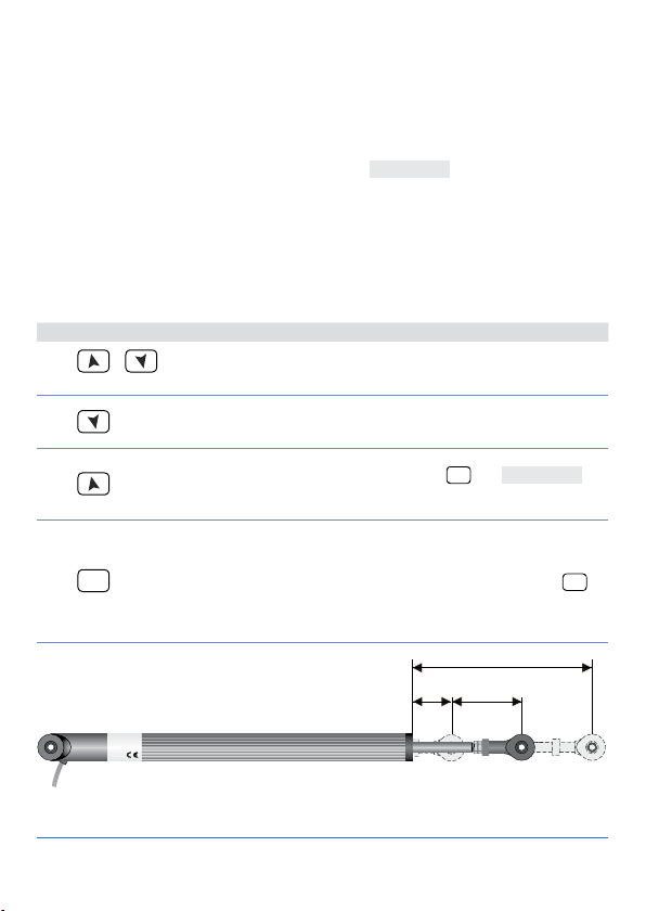
7.9 Latch-on function
Max
For use with in put
linear input (0…10 V, 0...40 mV, 0/4…20 mA), it is possible to associate start value of the
scale (parameter 6
(parame ter 7
as
Std .
It is also possible to fi x the point in which the controller will display 0 (however keeping
the scale range between
or
u.in.
If you set
the virtual zero remains fi xed once tuned.
Selecting “
input there are values out of 0/4…20mA or 0…10V .
To enable the LATCH ON func tion select chosen confi guration for parameter
For the calibration procedure refer to the following table:
1
2
3
4
u P.L.i
).
in parameter 8
u.in.
dYn .L
+
simultaneously
SET
(potentio meter 6 KΩ) and
P o t .1
) to the minimum position of the sensor and value of end scale
Lo L.i
) to the maxim um position of the sens or (parameter 8
and
Lo L.i
.
La t c
the virtual zero will reset af ter each activation of the tool; if you set
” (dynamic limits) it is possible to surpass lower and upper limits if on
) using the “vi rtual zero” option by setting
u P.L.i
(potentio meter 150 KΩ) and with
Po t.2
La t c .
confi gured
LA t c
Press Display Do
Exit parameters confi guration. Display 2 shows the
writing
Set the value on minimum.
Display shows
Set the value to maximum.
The display shows
Set the vir tual zero value.
Display shows
NB: For selection of
the procedure in point 4
should be followed on each
re-activation.
LA t c
.
Lo
ui r t
.
Hi G H
.
u.0in.
Place the sensor on minimum
operating value (associated
with
Place the sensor on maximum
operating value (associated
with
To exit standard procedure
press
.
settings place the sensor on
the zero point.
To exit procedure press
).
Lo L.i .
).
u p L.i .
SET
. For “virtu al zero”
u .St.
u .St.
2
.
SET
.
Min Zero
2
The tuning p rocedure starts b y exiting the confi guratio n after changin g the parameter.
20 - ATR243 - User manual
Page 21

7.10 Loop Break Alarm On Current Trasformer
This function allows to measure load current and to manage an alarm during malfunctioning (with power in short circuit or always off).
The current transformer connected to terminals 15 and 16 must be 50 mA (sampling time
80 ms).
• Set end scale value of the current transformer in Amperes on parameter 47
• Set the intervention threshold of the Loop Break Alarm in Amperes on parameter 48
L.b.a.t.
• Set the intervention delay time of the Loop Break Alarm on parameter 49
• It is possible to associate the alarm with a relay by setting the parameter
as
AL. 3
If a remote control switch or SSR remains closed, controller signals the fault
by showing
If the power s tage remains ope n, or the load current i s lower than the value se t on
controller shows
the closure phase of the power stage.
1
Settin g on parameter 48
without generating the Loop Break Alarm.
AL. 4.
on display 2 (alternatively with a command setpoint).
L.b.a.c.
on display. It is possible to display the current absorbed during
L.b.a.o.
Press Display Do
Press
am.t.a.
1 and display 2 shows the
current in amperes (
The value is also maintained
when no current circulates on
the load.
SET
This key enables to scroll
on display 2 the output
percentage, auto / man
selection, setpoint and
alarms.
the value 0 it is p ossible to visualize t he current absorbe d
L.b.A.t.
SET
until the writing
appears on display
t.a .
L.b.a.d.
AL. 1, AL. 2
L.b.a.t.
>0).
t. a .
or
,
ATR243 - User manual - 21
Page 22

7.11 Digital Input Functions
On CN243 model dig ital input can be e nabled by using par ameters 59
• Parameter 59
NB: When using this settings, parameter 61
2t.s .
with closed contact regulates on SET2;
2 t. s .i.
digital input;
3 t. s.i .
4 t. s .i
t. res .
p.c.s.s.
Setpoints values can be modified any time pressing
• Parameter 61
NB: Settings on this parameter are available only if
parameter 59
st. st.
start to stop;
rn.n.o.
rn.n.c.
L.c.n.o.
Lc.n . c.
tun e
a.ma.i.
automatic to manual functioning;
a.ma.c.
mode if input is open or in manual mode if input is closed.
NB: The digital input functions are not available with sensors PT100 and NI100 on model
CN243-R1F 2.
op.mo.
: Switch two thresholds setpoint: with open contact CN243 regulates on SET1;
: Switch two thresholds setpoint: setpoint selection is done by an impulse on
: Switch three thresholds setpoint by an impulse on digital input;
: Switch four thresholds setpoint by an impulse on digital input;
: Customized function;
: Pre-programmed cycle (see paragraph 7.7).
d G t.i .
op.mo.
: Start / Stop; o perating on digit al input the controlle r switches alternati vely from
: Run N.O. Controller is in start only with closed input;
: Run N.C. Controller is in start only with open input;
: With closed input allows to lock the reading of sensors;
: With open input allows to lock the reading of sensors;
: Enables / disables Tuning function if parameter 57
: If parameter 60
: If parameter 60
au.ma.
au.ma.
is selected as
is selected as
d G t.i .
en.
is ignored.
SET
co nt.
or
en.
or
en.st.
key.
or
tun e
controller switch from
en.st.
CN243 works in automatic
and 61
op.mo.
are selected on
p r. cY.
is selected as
man.
d G t.i .
;
22 - ATR243 - User manual
Page 23
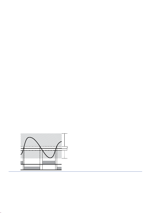
7.12 Dual Action Heating-Cooling
SPV
CN243 is suitable also for systems requiring a combined heating-cooling action.
Command output must be configured as Heating P.I.D. (
greater than 0), and one of the alarms (
Command output must be connected to the actuator responsible for heat, while the
alarm will control cooling action.
Parameters to configure for the Heating P.I.D. are:
=
Act. t.
: Heating proportional band;
P. b .
: Integral time heating and cooling;
t.i
: Derivative time heating and cooling;
t.d .
: Heating time cycle.
t. c.
Parameters to configure for the Cooling P.I.D. are the following (ex: action associated to
alarm 1):
=
A L .1
P. b . M .
ou.d.b.
co.t.c.
Parameter
cooling basing on the formula:
Cooling proportional band =
This gives a proportional band for cooling which will be the same as heating band i f
= 1.00, or 5 times greater if
Integral and derivative time are the same for both actions.
Parameter
systems in which the heating and cooling output must never be simultaneously active a
dead band (
The following figure shows an example of dual action P.I.D. (heating-cooling) with
0 and
1
Command output type (Heating);
HEAT
Alarm 1 selection (Cooling);
coo L
: Proportional band multiplier;
: Overlapping / Dead band;
: Cooling time cycle.
(that ranges from 1.00 to 5.00) determines the proportional band of
p.b.m.
P. b .
= 5.00.
P. b . M .
determines the percentage overlapping between the two actions. For
ou.d.b.
≤ 0) can be configured, and vice versa an overlapping (
ou.d.b.
= 0.
t.d .
PV
ACTIVE
ACTIVE
x
P. b . M .
or
A L .1, AL. 2
x = COOL
< 0
(HEAT)
COMMAND OUTPUT (HEAT)
ALARM OUTPUT (COOL)
AL. 3
=
Act. t.
) must be configured as
and with a
HEAT
ou.d.b.
co oL.
P. b . M .
> 0).
t.i .
P. b .
=
ATR243 - User manual - 23
Page 24
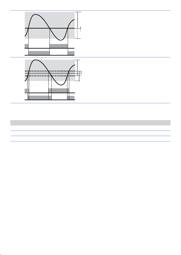
ACTIVE
ACTIVE
SPV
PV
x = COOL
x = COOL
< 0
(HEAT)
COMMAND OUTPUT (HEAT)
ALARM OUTPUT (COOL)
ALARM OUTPUT (COOL)
SPV
ACTIVE
ACTIVE
SPV
PV
x = COOL
x = COOL
< 0
= 0
(HEAT)
(HEAT)
COMMAND OUTPUT (HEAT)
ALARM OUTPUT (COOL)
COMMAND OUTPUT (HEAT)
ALARM OUTPUT (COOL)
SPV
PV
ACTIVE
ACTIVE
2
PV
ACTIVE
SPV
3
PV
ACTIVE
Parameter
Parameter
the cooling P.I.D. time cycle
co.t.c.
co o . f.
c o o . F.
Ai r
oi L
H2o
Once selected, parameter
changed.
ACTIVE
ACTIVE
has the same meaning as the heating time cycle
(cooling fluid) pre-selects the proportional band multiplier
co.t.c.
Cooling fluid type
Air 1.00 10
Oil 1.2 5 4
Water 2.50 2
co o . f.
= 0
(HEAT)
COMMAND OUTPUT (HEAT)
x = COOL
> 0
(HEAT)
COMMAND OUTPUT (HEAT)
ALARM OUTPUT (COOL)
basing on the type of cooling fluid:
P. b . M . co.t.c
, parameters
P. b . M ., oud.b.
and
t. c.
can however be
co.t.c.
8 Serial Communication
CN243-R1R2F3, equipped with RS485, can receive and broadcast data via serial
communication using MODBUS RTU protocol. The device can only be configured as a
Slave. This fun ction enables th e control of multiple cont rollers connec ted to a superviso ry
system (SC ADA). Each contro ller responds to a maste r query only if the qu ery contains the
same addr ess as that in the paramet er
and there must not be controllers with the same address on the same line.
Address 255 can b e used by the master to co mmunicate with al l the connected e quipment
(broadcast mode), while with 0 all the devices receive the command, but no response is
expected. CN243 can introduce a delay (in milliseconds) in the response to the master
request. This delay must be set on parameter 72
by the controller on EEPROM memory (100000 writing cycles), while the setpoints are
saved with a delay of ten seconds after the last change.
NB: changes made to Words that are different from those reported in the following table
can lead to malfunction.
The perm itted addresses r ange from 1 to 254
SL. Ad .
Each parameter change is saved
se. d e.
P. b . M .
and
24 - ATR243 - User manual
Page 25

Modbus RTU protocol features
Selection on parameter 70
4.800 bit/Sec.
4.8 k
9.600 bit/Sec.
9.6 k
Baud-rate
Format 8, N, 1 (8 bit, no parity, 1 stop)
Supported
functions
Looking at the table here below it is possible to find all available addresses and functions:
RO Read Only R/W Read / Write WO Write Only
19.200 bit/Sec.
19.2k
28.800 bit/Sec.
28.8 k
38.400 bit/Sec.
38 .4 k
57.600 bit/Sec.
57.6 k
WORD READING (max 20 word) (0x03, 0x04)
SINGLE WORD WRITING (0x06)
MULTIPLE WORDS WRITING (max 20 word) (0x10)
bd . rt.
:
Modbus
Address
0 Device type RO EEPROM
1 Software version RO EEPROM
5 Slave address R/W EEPROM
6 Boot version RO EEPROM
50 Automatic addressing WO 51 System code comparison WO -
500 Loading default values (write 9999) R/W 0
510 Setpoints storing time in eeprom (0 -60 s) R/W 10
999 Process subjected to the visualization filter RO -
Process (degrees.tenths for temperature sensors;
1000
digits for linear sensors)
1001 Setpoint 1 R/W EEPROM
1002 Setpoint 2 R/W EEPROM
1003 Setpoint 3 R/W EEPROM
100 4 Setpoint 4 R/W EEPROM
1005 Alarm 1 R/W EEPROM
1006 Alarm 2 R/W EEPROM
1007 Alarm 3 R/W EEPROM
1008 Setpoint gradient RO EEPROM
Relay status (0 = Off, 1 = On):
Bit 0 = Relay Q1
1009
Bit 1 = Relay Q2
Bit 2 = Reser ved
Bit 3 = SSR
1010 Heating output percentage (0-10000) RO 0
Description Read Only
RO -
RO 0
ATR243 - User manual - 25
Reset
value
Page 26

Modbus
Address
Description Read Only
1011 Cooling output percentage (0-10000) RO 0
Alarms status (0 = None, 1 = Active)
1012
Bit 0 = Alarm 1 Bit 1 = Alarm 2 Bit 2 = Alarm 3
RO 0
Manual reset: write 0 to reset all alarms.
1013
In reading (0 = Not resettable, 1 = Resettable)
WO 0
Bit 0 = Alarm 1 Bit 1 = Alarm 2 Bit 2 = Alarm 3
Error flags
Bit 0 = Eeprom writing error
Bit 1 = Eeprom reading error
Bit 2 = Cold junc tion error
Bit 3 = Process error (sensor)
1014
Bit 4 = Generic error
RO 0
Bit 5 = Hardware error
Bit 6 = L.B.A.O. error
Bit 7 = L.B.A.C. error
Bit 8 = Missing calibration data error
1015 Cold junction temperature (degrees.tenths) RO -
Start / Stop
1016
0 = Controller in STOP
R/W 0
1 = Controller in START
Lock conversion ON / OFF
1017
0 = Lock conversion off
R/W 0
1 = Lock conversion on
Tuning ON / OFF
1018
0 = Tuning off 1 = Tuning on
Automatic / manual selection
1019
0 = Automatic 1 = Manual
R/W 0
R/W 0
1020 T.A. current ON (Ampere with tenths) RO 1021 T.A. current OFF (Ampere with tenths) RO
1022 OFF LINE* time (milliseconds) R/W
1023 Instant Current (Ampere) R/W 0
1024 Digital Input State R/W 0
Synchronized Tuning for multizone system
0 = Tuning OFF (Normal operating of the regulator)
1 = Output command OFF
2 = Output command ON
1025
3 = Start Tuning
R/W 0
4 = End Tuning and output command OFF (Write
0 for normal operating)
Process subjected to the visualization filter and
1099
decimal point selection
RO
110 0 Process with decimal point selection RO
1101 Setpoint 1 with decimal point selection R/W EEPROM
26 - ATR243 - User manual
Reset
value
Page 27

Modbus
Address
Description Read Only
Reset
value
110 2 Setpoint 2 with decimal point selection R/W EEPROM
110 3 Setpoint 3 with decimal point selection R/W EEPROM
110 4 Setpoint 4 with decimal point selection R/W EEPROM
110 5 Alarm 1 with decimal point selec tion R/W EEPROM
110 6 Alarm 2 with decimal point selection R/W EEPROM
110 7 Alarm 3 with decimal point selection R/W EEPROM
110 8 Gradient Setpoint with decimal point selection RO EEPROM
110 9 Percentage heating output (0-1000) R/W 0
1110 Percentage heating output (0-100) RO 0
1111 Percentage cooling output (0-1000) RO 0
1112 Percentage cooling output (0-100) RO 0
2001 Parameter 1 R/W EEPROM
2002 Parameter 2 R/W EEPROM
2072 Parameter 72 R/W EEPROM
3000 Disabling serial control of machine** RO 0
3001 First word display 1 (ascii) R/W 0
3002 Second word display 1 (ascii) R/W 0
3003 Third word display 1 (ascii) R/W 0
3004 Fourth word display 1 (ascii) R/W 0
3005 Fif th word display 1 (ascii) R/W 0
3006 Sixth word display 1 (ascii) R/W 0
3007 Seventh word display 1 (ascii) R/W 0
3008 Eighth word display 1 (ascii) R/W 0
3009 First word display 2 (ascii) R/W 0
3010 Second word display 2 (ascii) R/W 0
30 11 Third word display 2 (ascii) R/W 0
3012 Fourth word display 2 (ascii) R/W 0
3013 Fifth word display 2 (ascii) R/W 0
3014 Six th word display 2 (ascii) R/W 0
3015 Seventh word display 2 (ascii) R/W 0
3016 Eight word display 2 (ascii) R/W 0
Word LED
Bit 0 = LED C1
Bit 1 = LED C2
Bit 2 = LED A1
3017
Bit 3 = LED A2
Bit 4 = LED A3
R/W 0
Bit 5 = LED MAN
Bit 6 = LED TUN
Bit 7 = LED REM
ATR243 - User manual - 27
Page 28

Modbus
Address
Description Read Only
Reset
value
Word keys
(write 1 to command keys)
3018
Bit 0 =
Bit 1 =
Bit 2 =
SET
R/W 0
Word serial relay
Bit 0 = Relay Q1
3019
Bit 1 = Relay Q2
R/W 0
Bit 2 = Relay Q3
3020 Word SSR serial (0 = Off, 1 = On) R/W 0
3021 Word output 0...10 V serial (0…10000) R/W 0
3022 Word output 4...20 mA serial (0…10000) R/W 0
Relay state in case of off- line
(only if controlled by serial)
3023
Bit 0 = Relay Q1
R/W 0
Bit 1 = Relay Q2
Bit 2 = Relay Q3
Output state SSR / 0…10 V / 4…20 mA in case of
3024
off-line (only if controlled by serial)
R/W 0
(0…10000)
Serial process. Set ting parameter 54 it is possible
3025
to make averages on the remote process
R/W 0
4001 Parameter 1*** R/W EEPROM
4002 Parameter 2*** R/W EEPROM
4072 Parameter 72*** R/W EEPROM
* If value is 0 , control is disabled . If different from 0, it is t he max. time that can e lapse between t wo pollings
before the co ntroller goes off- line. If it goes off-l ine, the controller r eturns to Stop mode, contr ol output is
disabled but the alarms are active.
** B y writing 1 on this word, t he effects of the wr iting are cancelle d on all the Modbus a ddresses from 30 01 to
3022. Control the refore returns to the co ntroller.
*** Parameters modifi ed using serial address 4001 to 4072 will be stor ed on eepro m only after 10” since last
writing of one parameter.
28 - ATR243 - User manual
Page 29
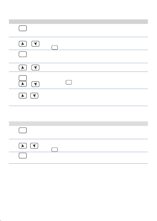
9 Enter configuration
For configuration parameters see paragraph 10.
Press Display Do
1
2
3
4
5
SET
for 3 seconds
or
SET
to confirm
or
SET
or
Display 1 shows
the 1st digit flashing, while
display 2 shows
Changes flashing digit and
move to the nex t one using
SET
key.
Display 1 shows the first
parameter and display 2
shows the value.
Slide up / down through
parameters.
Increase or decrease
displayed value by keep
SET
pressing
arr ow key.
with
0.000
.
PASS
and after an
Enter password:
Enter new data which will be
saved on releasing the keys.
To change another parameter
return to point 4.
End of configuration
6
simultaneously
+
parameter change.
The controller exits from
programming.
9.1 Loading default values
This procedure allows to restore factory settings of the instrument.
1
2
3
Press Display Do
SET
for 3 seconds
o
SET
to confirm
Display 1 visualizes
with 1st digit blinking, while
display 2 shows
PASS
0.000
.
Change blinking digit and
move to the nex t one with
SET
.
Device loads default settings.
Enter password:
Turn off and restar t the
instrument.
1234
9999
.
.
ATR243 - User manual - 29
Page 30

10 Table of Configuration Parameters
The following table includes all parameters. Some of them will not be visible on the
models which are not provided with relevant Hardware data.
1
3
4
30 - ATR243 - User manual
Command Output
C.out
Command output type selection (see tables).
Default (necessary for using process and setpoint retransmission function
c. o1
with Volt / mA output)
Command on relay output Q2
c. o2
Command in tension for SSR
c.SS r
Servo-valve command with open loop
c. uA L.
4...20 mA command
c.4 . 2 0
0...20 mA command
c.0.20
c.0.10
0...10 V command
4
3
4
4
4
3
CN243- R1F2
COMMA ND ALARM 1
c. o1
c. o2
c.SS r
c. uA L.
c.4 . 2 0
c.0.20
c.0.10
Q1 (opens) / Q2 (closes) -
Q1 Q2
Q2 Q1
SSR Q1
4 ... 20 mA Q1
0 ... 20 mA Q1
0 ... 10 V Q1
CN243-R1R2F3
COMMA ND AL ARM 1 ALARM 2
c. o1
c. o2
c.SS r
c. uA L.
c.4 . 2 0
c.0.20
c.0.10
Q1 (opens) / Q2 (closes) SSR -
Q1 Q2 SSR
Q2 Q1 SSR
SSR Q1 Q2
4 ... 20 mA Q1 Q2
0 ... 20 mA Q1 Q2
0 ... 10 V Q1 Q2
CN243- R1R2R 3F4C4
COMMA ND ALARM 1 ALARM 2 ALARM 3
c. o1
c. o2
c.SS r
c. uA L.
Q2 (opens) / Q3 (closes) Q1 SSR -
c.4 . 2 0
c.0.20
c.0.10
Only on CN243-R1F2 do not sel ect if process retra nsmission functi on is used.
Do not selec t if process retransm ission functio n is used.
Q1 Q2 Q3 SSR
Q2 Q1 SSR SSR
SSR Q1 Q2 Q3
4 ... 20 mA Q1 Q2 Q3
0 ... 20 mA Q1 Q2 Q3
0 ... 10 V Q1 Q2 Q3
Page 31

2
Sensor
SEN.
Analogue input configuration/sensor selection
Tc- K (Default) -260 °C .. 1360 °C
Tc.K
Tc-S -40 °C .. 1760 °C
Tc. s
Tc-R -40 °C .. 1760 °C
Tc. r
Tc-J -200 °C .. 1200 °C
Tc. j
Pt100 -200 °C .. 600 °C
Pt
Pt100 -200 °C .. 140 °C
P t1
NI100 -60 °C .. 180 °C
ni
NTC10K-β3435K -40 .. 125°C
n t c .1
NTC10K-OMEGA -40 .. 150°C
n tc.2
NTC2252-OMEGA -40 .. 150°C
n tc.3
PTC1K -50 °C .. 150 °C
Ptc
Pt500 -100 °C .. 600 °C
Pts
Pt1000 -100 °C .. 600 °C
P t1 k
0 .. 10 Volt
0 .1 0
0 .. 20 mA
0.20
4 .. 20 mA
4.20
0 .. 40 mVolt
0.4 0
Potentiometer max 6 Kohm (Se e paragraph 7.9)
P o t .1
Potentiometer max 150 Kohm (See para graph 7.9)
Po t.2
50 mA secondary Current transformer (Only CN243-R1R2F3/CN243-
t.A.
R1R2 R3F4C4)
3
Decimal Point
d .P.
Select type of visualized decimal point
Default
0
1 Decimal
0.0
2 Decimal
0.00
3 Decimal
0.000
4
5
6
Lower Limit Setpoint
Lo . L. S.
Lower limit selectable for setpoint
-999…+9999 [digit
Upper Limit Setpoint
u p . L.S.
Upper limit selectable for setpoint
-999…+9999 [digit
Default: 1750 .
Lower Linear Input
Lo L.i
Range AN1 lower limit only for linear. Example: with input 4...20 mA this parameter
takes value associated to 4 mA
-999 bis +9999 [digit
5
] (degrees.tenths for temperature sensors), Default: 0.
5
] (degrees.tenths for temperature sensors),
5
], Default: 0.
ATR243 - User manual - 31
Page 32

7
8
9
10
11
12
13
Upper Linear Input
u p . L.i .
Range AN1 upper limit only for linear. Example: with input 4...20 mA this parameter
takes value associated to 20 mA
-999 bis +9999 [digit
Latch On Function
La t c .
Automatic setting of limits for linear inputs and potentiometers (See para graph 7.9)
Disabled (Default)
di s .
Standard
std .
Virtual zero stored
u.0 st.
Virtual zero initialized
u .0i n
Allows to surpass lower and upper limits if on input there are values out of
dYn .L
0/4…20mA or 0…10V.
Offset Calibration
o . cAL.
Value added / subtracted to process visualization (usually correcting the value of
environment temperature)
-999…+1000 [digit
-200.0…+100.0 (degrees.tenths for temperature sensors), Default 0.0.
Gain Calibration
G. cAL.
Percentage value that is multiplied for the process value (allows to calibrated the
working point)
-9 9.9%…+1 00.0 % ( Default = 0.0)
ex: to correct the range from 0...1000°C showing 0...1010°C, set the parameter to -1.0.
Action type
Act. t.
Regulation type
Heating (N.O.) (Default)
Heat
Cooling (N.C.)
coo L
Lock command above SPV. Example: command output disabled when
H.o.o.S.
reaching setpoint, also with P.I.D. value different from 0
Command Reset
c. re.
Type of reset for state of command contact (always automatic in P.I.D. functioning)
Automatic reset (Default)
a re.
Manual reset
m re.
Manu al reset stored (keep s relay status also af ter an eventual power fa ilure)
m re.s .
Command State Error
c. S.e.
State of contac t for command output in case of error
Open contact (Default)
c. o .
Closed contact
c. c.
5
], Default: 1000.
5
] for linear sensors and potentiometers.
32 - ATR243 - User manual
Page 33

14
15
16
17
18
19
20
21
22
5
Command Led
c. Ld.
State of the OUT1 led corresponding to the relevant contact
ON with open contact
c. o .
ON with closed contac t (Default)
c. c.
Command Hysteresis
c. HY.
Hysteresis in ON/OFF or dead band in P.I.D.
-999…+999 [digit
Command Delay
c. de.
Command delay (only in ON / OFF functioning). In case of servo valve it also works
in P.I.D. and represents the delay between opening and closure of the two contacts
-180…+180 seconds (tenths of second in case of ser vo valve).
Negative: delay in switching off phase.
Positive: delay in activation phase.
Default: 0.
Command Setpoint Protection
c. s. p.
Allows or not to modify the command setpoint value
Modification allowed (Default)
free
Protected
Lo c k
Proportional Band
p. b .
Proportional band Process inertia in units (example: if temperature is in °C)
0 ON / OFF
1-9999 [digit
Integral Time
t.i .
Process iner tia in seconds
0.0-999.9 seconds (0 = integral disabled), Default: 0.0
Derivative Time
t.d.
Normally ¼ of integral time
0.0-999.9 seconds (0 = derivative disabled), Default: 0.0
Cycle T ime
t. c.
Cycle time (for P.I.D. on remote control switch 10 / 15 sec., for P.I.D. on SSR 1 sec.) or
servo time (value declared by ser vo-motor manufacturer)
1-300 seconds, Default: 10.
Output Power Limit
o . P o L.
Select max. value for command output percentage
0…10 0%, Default: 100 %.
Es: with
from a min. of 0 V to a max. of 9 V.
Display of d ecimal point dep ends on setting o f parameter
5
] (degrees.tenths for temperature sensors), Default 0.0.
if equal to 0 (Default)
t.i .
5
] (degrees for temperature sensors)
selected as 0...10 V and
c.out
as 90%, com mand output can modulate
o . Po L.
and parameter
sen.
d. p.
ATR243 - User manual - 33
Page 34

23
Alarm 1
A L .1
Alarm 1 selection. Alarm intervention is related to AL1. (See parag raph 11)
Disabled (Default)
di s .
Absolute alarm, referring to process
A. AL.
Band alarm
b . AL.
Upper deviation alarm
H. d. A L.
Lower deviation alarm
L. d .AL.
Absolute alarm, referring to command setpoint
A. c.AL.
Status alarm (active in Run / Start)
s t .A L.
Cooling action
coo L
Status alarm “load control” (Loop Break Ala rm). Example: sta tus of contactor s
L. b .A.
/ SSR or heating elements
24
25
26
27
28
Alarm 1 State Output
A.I.5.0
Alarm 1 output contact and intervention type
(N.O. Start) Normally open, active at start (Default)
n . o . s.
(N.C. Start) Normally closed, active at star t
n . c. s.
(N.O. Threshold) Normally open, active on reaching alarm
n . o . t.
(N.C. Threshold) Normally closed, active on reaching alarm
n . c. t.
Alarm 1 Reset
a1 . r e .
Alarm 1 contact reset t ype
Automatic reset (Default)
a re.
Manual reset
m re.
Manual reset stored. (keeps relay status also after an eventual power
m re.s .
failure)
Alarm 1 State Reset
a .1 . s . e .
State of contac t for alarm 1 output in case of error
Open contact (Default)
c. o .
Closed contac t
c. c.
Alarm 1 Led
a.1.Ld.
Defines the state of OUT2 led corresponding to the relative contact
ON with open contact
c. o .
ON with closed contact (Default)
c. c.
Alarm 1 Hysteresis
a .1 . H y .
-999…+999 [digit7] (degrees.tenths for temperature sensors), Default: 0.0.
SET
6
6
6
On activati on, the output is inhibi ted if the controller is in al arm mode. Activates on ly if alarm condition
reapper s, after that it was r estored.
7
Display of d ecimal point dep ends on setting o f parameter
34 - ATR243 - User manual
and parameter
sen.
d. p.
Page 35

29
30
31
32
33
34
Alarm 1 Delay
a .1 . d e .
-180…+180 s econ ds.
Negative: delay in alarm output phase.
Positive: delay in alarm entr y phase.
Default: 0.
Alarm 1 Setpoint Protection
a .1 . s p .
Alarm 1 set protection. Does not allow user to modify setpoint
Modification allowed (Default)
free
Protected
Lo c k
Protected and not visualized
Hi d e
Alarm 2
AL. 2
Alarm 2 selection. Alarm intervention is related to AL 2. (See paragraph 11)
Disabled (Default)
di s .
Absolute alarm, referring to process
A. AL.
Band alarm
b . AL.
Upper deviation alarm
H. d. A L.
Lower deviation alarm
L. d .AL.
Absolute alarm, referring to command setpoint
A. c.AL.
Status alarm (active in Run / Start)
s t .A L.
Cooling action
coo L
Status alarm “load control” (Loop Break Ala rm). Example: sta tus of contactor s
L. b .A.
/ SSR or heating elements
Alarm 2 State Output
a . 2. s o .
Alarm 2 output contact and intervention type
(N.O. Start) Normally open, active at start (Default)
n . o . s.
(N.C. Start) Normally closed, active at star t
n . c. s.
(N.O. Threshold) Normally open, active on reaching alarm
n . o . t.
(N.C. Threshold) Normally closed, active on reaching alarm
n . c. t.
Alarm 2 Reset
A2. re.
Alarm 2 contact reset t ype
Automatic reset (Default)
Are.
Manual reset (reset / manual reset by keyboard)
m re.
Manual reset stored. (keeps relay status also after an eventual power
m re.s .
failure)
Alarm 2 State Error
a . 2. s . e .
State of contac t for alarm 2 output in case of error
Open contact (Default)
c. o .
Closed contac t
c. c.
SET
8
8
8
On activati on, the output is inhibi ted if the controller is in al arm mode. Activates on ly if alarm condition
reapper s, after that it was r estored.
ATR243 - User manual - 35
Page 36

35
36
37
38
39
40
Alarm 2 Led
a.2.Ld.
State of OUT2 led corresponding to relative contact
ON with open contact
c. o .
ON with closed contact (Default)
c. c.
Alarm 2 Hysteresis
a.2.HY.
-999…+999 [digit9] (degrees.tenths for temperature sensors), Default: 0.0.
Alarm 2 Delay
a.2.d.e.
-180…+180 s econ ds.
Negative: delay in alarm exit phase.
Positive: delay in alarm entr y phase.
Default: 0.
Alarm 2 Setpoint Protection
a . 2. s . p .
Alarm 2 set protection. Does not allow operator to change value set
Modification allowed (Default)
free
Protected
Lo c k
Protected and not visualized
Hi d e
Alarm 3
AL. 3
Alarm 3 selection. Alarm intervention is associated with AL3. (S ee paragraph 11)
Disabled (Default)
di s .
Absolute alarm, referring to process
A. AL.
Band alarm
b . AL.
Upper deviation alarm
H. d. A L.
Lower deviation alarm
L. d .AL.
Absolute alarm, referring to command setpoint
A. c.AL.
Status alarm (active in Run / Start)
s t .A L.
Cooling action (See para graph 12)
coo L
Status alarm “load control” (Loop Break Ala rm). Example: sta tus of contactor s
L. b .A.
/ SSR or heating elements
Alarm 3 State Output
a .3.5. o .
Alarm 3 output contact and intervention type
(N.O. Start) Normally open, active at start (Default)
n . o . s.
(N.C. Start) Normally closed, active at star t
n . c. s.
(N.O. Threshold) Normally open, active on reaching alarm
n . o . t.
(N.C. Threshold) Normally closed, active on reaching alarm
n . c. t.
10
10
9
Display of d ecimal point dep ends on setting o f parameter
10
On activati on, the output is inhibi ted if the controller is in al arm mode. Activates on ly if alarm condition
reapper s, after that it was r estored.
36 - ATR243 - User manual
and parameter
sen.
d. p.
Page 37

41
42
43
44
45
46
47
48
Alarm 3 Reset
a .3. re .
Alarm 3 contact reset t ype
Automatic reset (Default)
a re.
Manual reset
m re.
Manual reset stored. (keeps relay status also after an eventual power
m re.
failure)
Alarm 3 State Error
a .3.s . e.
State of contac t for alarm 3 output in case of error
Open contact (Default)
c. o .
Closed contac t
c. c.
Alarm 3 LED
a.3.Ld.
State of OUT3 led corresponding to relative contact
ON with open contact
c. o .
ON with closed contact (Default)
c. c.
Alarm 3 Hysteresis
a .3.HY.
-999…+999 [digit11] (degrees.tenths for temperature sensors), Default: 0.0.
Alarm 3 Delay
a .3. d e.
-180…+180 seconds
Negative: delay in alarm exit phase.
Positive: delay in alarm entr y phase.
Default: 0.
Alarm 3 Setpoint Protection
a .3.s . p.
Alarm 3 set protection. Does not allow operator to change the setpoint value
Modification allowed (Default)
free
Protected
Lo c k
Protected and not visualized
Hi d e
Current Transformer
t.a.
Activation and scale range of current transformer
0 Disabled
1-200 Ampere
Default: 0
Loop Break Alarm Threshold
L.b.a.t.
Intervention threshold of Loop Break Alarm
0.0-200.0 Ampere
Default: 50.0
11
Display of d ecimal point dep ends on setting o f parameter
and parameter
sen.
d. p.
ATR243 - User manual - 37
Page 38

49
50
51
52
53
co.t.c.
54
Loop Break Alarm Delay
L.b.a.d.
Delay time for Loop break alarm inter vention
00.00- 60.00 mm.ss
Default: 01.0 0
Cooling Fluid
co o .f.
Type of refrigerant fluid for heating / cooling P.I.D.
Air (Default)
Ai r
Oil
oi L
Water
H2o
Proportional Band Multiplier
p.b.m.
Proportional band multiplier. Proportional band for cooling action is given by
parameter 18 multiplied for this parameter
1.00-5.00 (Default: 1.0 0)
Overlap / Dead Band
oud.b.
Dead band combination for heating / cooling action in heating / cooling P.I.D. mode
(dual action)
-20.0-50.0% of propor tional band value (Default: 0).
Negative indicates dead band value.
Positive means overlap.
Cooling Cycle Time
Cycle time for cooling output
1-300 seconds, Default: 10.
Conversion Filter
c. fLt.
ADC Filter: Number of input sensor readings to calculate the mean that defines
process value. NB: When means increase, control loop speed slows down
Disabled
di s .
2 Samples Mean
2. s. m .
3 Samples Mean
3. s. m .
4 Samples Mean
4. s. m .
5 Samples Mean
5. s. m .
6 Samples Mean
6. s. m .
7 Samples Mean
7. s. m .
8 Samples Mean
8. s. m .
9 Samples Mean
9. s. m .
10 Samples Mean (Default)
10.s . m .
11 Samples Mean
11 . s . m .
12 Samples Mean
12. s . m .
13 Samples Mean
13.s .m .
14 Samples Mean
14.s . m.
15 Samples Mean
15.s . m.
38 - ATR243 - User manual
Page 39

55
56
57
58
Conversion Frequency
c. frn .
Sampling frequency of analogue / digital converter.
NB: Increasing the conversion speed will slow down reading stability (example: for
fast transients, as pressure, it is advisable to increase sampling frequenc y)
242 Hz (Maximum speed conversion)
242H.
123 Hz
123H.
62 Hz
62 H.
50 Hz
50 H.
39 Hz
39 H.
33.2 Hz
33.2 H.
19.6 Hz
19.6H.
16.7 Hz (Default) Ideal for filtering noises 50 / 60 Hz
1 6 .7H .
12 .5 H z
12.5 H.
10 Hz
10 H.
8.33 Hz
8.33H.
6.25 Hz
6.25H .
4.17 Hz (Minimum speed conversion)
4 .1 7 H.
Visualization Filter
u . FLt .
Slow down the refresh of display, to simplif y reading
Disabled with pitchfork (max. speed of display update) Default.
di s .
First order filter with pitchfork
fi . o r.
2 Samples Mean
2. s. m .
3 Samples Mean
3. s. m .
4 Samples Mean
4. s. m .
5 Samples Mean
5. s. m .
6 Samples Mean
6. s. m .
7 Samples Mean
7. s. m .
8 Samples Mean
8. s. m .
9 Samples Mean
9. s. m .
10 Samples Mean (Maximum slow down of display update)
10.s . m .
Disabled without pitchfork
n u LL
First order filter
f. o . 2
Tun e
tun e
Tuning type selection. (See pa ragraph 7.2)
Disabled (Default)
diS .
Automatic (P.I.D. parameters are calculated at activation and at change of
Auto
set point)
Manual (launch by keyboard or digital IN)
Man.
Synchronized [see word modbus 1025 (only CN243-R1R2F3)]
sYn c.
Setpoint Deviation Tune
s.dtu .
Select the deviation from the command setpoint for the threshold used by
autotuning to calculate the P.I.D. parameters
ATR243 - User manual - 39
Page 40

0-5000 [digit12] (degrees.tenths if temperature).
Default: 10.
59
60
61
62
63
Operating Mode
op.mo.
Select operating mode. (See paragra ph 11)
Controller (Default)
co nt.
Pre-programmed cycle (See pa ragraph 7.7)
p r. cY.
Setpoint change by digital input
2t.s .
Setpoint change by digital input with impulse command
2t . s .i.
3 sets change by digital input with impulse command
3 t. s .i.
4 sets change by digital input with impulse command
4 t. s .i.
Reset time (custom function)
t. res .
Pre-programmed cycle with Star t / Stop only by digital input
p.c.s.s.
Automatic / Manual
au.ma.
Enable automatic / manual selection. (See p aragraph 7.6)
Disabled (Default)
di s .
Enabled
En.
Enabled with memory
En .St.
Digital Input
d G t .i .
Digital input functioning (P59 selection must be
Disabled (Default)
di s .
Star t / Stop
st.s t.
Run N.O. (enables regulation with N.O. contact)
rn.n.o.
Run N.C. (enables regulation with N.C. contact)
rn.n.c.
Lock conversion N.O. (stop conversion and display value with N.O.)
L.c.n.o.
Lock conversion N.C. (stop conversion and display value with N.C .)
L.c.n.c.
Manual Tune (by digital input)
tu n e
Automatic / Manual Impulse (if enabled on parameter 60)
a.ma.i.
Automatic / Manual Contac t (if enabled on parameter 60)
a.ma.c.
Gradient
Gra d .
Rising gradient for Soft-Start or pre-programmed cycle
0 Disabled (Default)
1-9999 [Digit/hour
Maintenance Time
m a . ti .
Maintenance time for pre-programmed cycle
00.00-24.00 hh.mm. Default: 00.00
13
] (degrees/hour with display of tenth for temperature sensor)
co nt.
or
Pr. cY .
). (See para graph 11)
12
Display of d ecimal point dep ends on setting o f parameter
13
Display of d ecimal point dep ends on setting o f parameter
40 - ATR243 - User manual
and parameter
sen.
and parameter
sen.
d. p.
d. p.
Page 41

64
65
66
67
68
69
14
User Menu Cycle Programmed
u.m.c.p.
Allows to modify rising gradient and maintenance time, from user menu, when preprogrammed cycle is operating
Disabled (Default)
di s .
Gradient
Gra d .
Maintenance time
m a . ti .
Both gradient and maintenance time
ALL
Visualization Type
ui . tY.
Select visualization for display 1 and 2
1 Process, 2 Setpoint (Default)
1. p.2. s .
1 Process, 2 Hide after 3 sec.
1. p.2.H.
1 Setpoint, 2 Process
1.s.2.P.
1 Setpoint, 2 Hide after 3 sec.
1.s .2.H.
1 Process, 2 Ampere ( T.A. input)
1.p.2.a.
Degree
d eG r.
Select degree type
Centigrade (Default)
c
Fahrenheit
f
Retransmission
re tr.
Retransmission for output 0-10 V or 4…20 mA (select Jumpers JP5, JP7 and JP9).
Parameters 68 and 69 define the lower and upper limits of the scale.
Disabled
di s .
Retransmits process in Volt
u o . p.
Retransmits process in mA
m a . p.
Retransmits command setpoint in Volt
u o . c.
Retransmits command setpoint in mA
m a . c.
Volt output percentage
uo.o.p.
mA output percentage
ma.o.p.
Volt alarm 1 setpoint
uo.a.1
mA alarm 1 setpoint
ma.a.1
Volt alarm 2 setpoint
uo.a.2
mA alarm 2 setpoint
ma.a.2
Vo lt T.A .
uo.t.a.
mA T. A.
ma.t.a.
Lower Limit Retransmission
Lo .L. r.
Output V / mA retransmission lower limit range
-999…+9999 [digit
Upper Limit Retransmission
up.L.r.
Output V / mA retransmission upper limit range
-999…+9999
The display o f the decimal poi nt depends on the se tting of paramete r
14
] (degrees.tenths for temperature sensors), Default: 0.
[digit14] (
degrees.tenths for temperature sensors
sen.
),
Default
: 1000.
and the parameter
ATR243 - User manual - 41
d. p.
Page 42
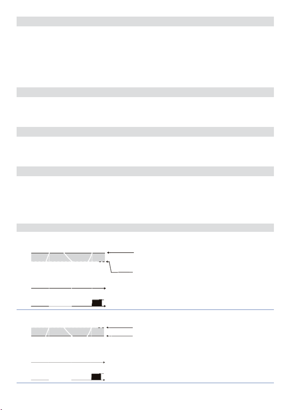
70
71
Baud Rate
bd . rt.
Select baud rate for serial communication
4.800 Bit/s
4.8 k
9.600 Bit/s
9.6 k
19.200 Bit/s (Default)
19.2k
28.800 Bit/s
28.8 k
39.400 Bit/s
39 .4 k
57.600 Bit/s
57.6 k
Slave Address
sL. a d .
Select slave address for serial communication
1 – 254.
Default: 254
72
Serial Delay
se. d e.
Select serial delay
0 – 100 milliseconds.
Default: 20
73
Lower Limit Output Percentage
L.L. o . p.
Selects min. value for command output percentage
0 – 100%, Default: 0%.
Ex: with
from a min. of 1 V to a max. of 10 V.
selec ted as 0...10 V and
c.out
L.L. o .P.
11 Alarm Intervention Modes
11. a Absolute Alarm or Threshold Alarm (
Pv
1
On On
O
2
On On
O
42 - ATR243 - User manual
O
O
Alarm Spv
Hysteresis
Absolute alarm with controller in heating
parameter
functioning (par. 11
> 0
and hysteresis value greater than “0” (par. 28
A.1. HY.
Time
Alarm
output
Hysteresis
parameter
< 0
Alarm Spv
Absolute alarm with controller in heating
functioning (par. 11
hysteresis value less than “0” (par. 28
< 0). *
Time
Alarm
output
set at 10%, comma nd output can change
selection)
a . AL.
Act. t.
selected
Heat
)
> 0). *
Act. t.
selected
Heat
A.1. HY.
) and
Page 43
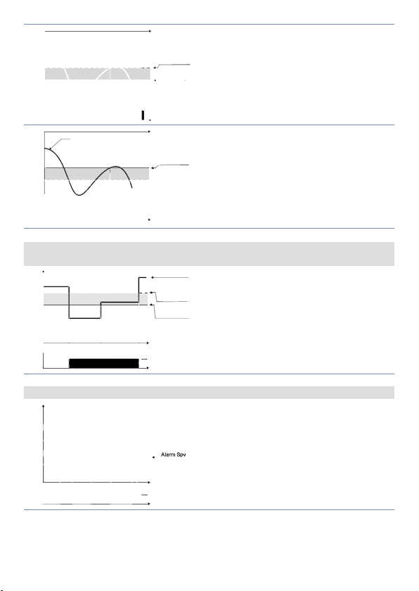
Time
output
Time
output
Comand Spv
output
Hysteresis
parameter
> 0
Absolute alarm with controller in cooling
functioning (par. 11
Alarm Spv
hysteresis value than “0” (par. 28
Alarm
Alarm Spv
Absolute alarm with controller in cooling
functioning (par. 11
Hysteresis
parameter
hysteresis value less than “0” (par. 28
< 0
< 0). *
Alarm
Act. t.
Act. t.
selected
A.1. HY.
selected
Co o L
Co o L
A.1. HY.
) and
> 0). *
) and
3
O
4
O O
Pv
On On
Pv
On On
O
11. b Absolute Alarm or Threshold Alarm Referring to Setpoint Command
(
selection)
a . c. AL.
Hysteresis
Absolute alarm refers to the command set,
parameter
> 0
with the controller in heating functioning (par.
11
1
On
O
Alarm Spv
greater than “0” (par. 28
The command set can be changed by pressing
Time
the arrow keys on front panel or using serial
port RS485 commands. *
Alarm
O
output
Act. t.
selected
) and hysteresis value
Heat
A.1. HY.
> 0). *
11. c Band Alarm (
Pv
1
On On On
O O
b . AL.
selection)
Hysteresis
parameter
> 0
Time
Alarm
Band alarm hysteresis value greater than “0”
A.1. HY.
> 0). *
ATR243 - User manual - 43
(par. 28
Page 44
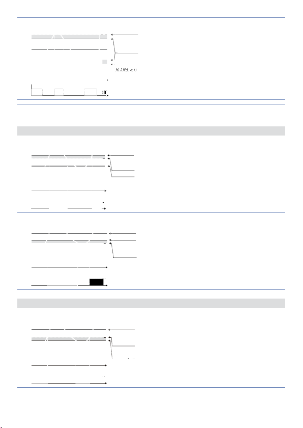
Hysteresis
Alarm Spv
Alarm Spv
Comand Spv
Comand Spv
Alarm Spv
Alarm Spv
Alarm Spv
Alarm Spv
parameter
< 0
Comand Spv
2
On On On
O O
* a) The e xample refe rs to alarm 1; the funct ion can also be ena bled for alarm 2 a nd 3 on models tha t include
it.
11. d Upper Deviation Alarm (
1
On On
O O
Pv
2
On On
O O
Alarm Spv
Band alarm hysteresis value less than “0” (par.
Hysteresis
parameter
Time
Alarm
output
H. d . AL.
Alarm Spv
Hysteresis
parameter
> 0
Comand Spv
Time
Alarm
output
Comand Spv
Alarm Spv
Hysteresis
parameter
> 0
Time
Alarm
output
< 0). *
28
A.1. HY.
selection)
Upper deviation alarm value of alarm setpoint
greater than “0” and hysteresis value greater
than “0” (par. 28
A.1. HY.
> 0). **
Upper deviation alarm value of alarm setpoint
less than “0” and hysteresis value greater than
“0” (par. 28
A.1. HY.
> 0). **
11. e Lower Deviation Alarm (
Pv
1
On On
O O
44 - ATR243 - User manual
selection)
L. d .A L.
Comand Spv
Hysteresis
parameter
Lower deviation alarm value of alarm setpoint
> 0
greater than “0” and hysteresis value greater
Alarm Spv
Time
Alarm
output
than “0” (par. 28
A.1. HY.
> 0). **
Page 45
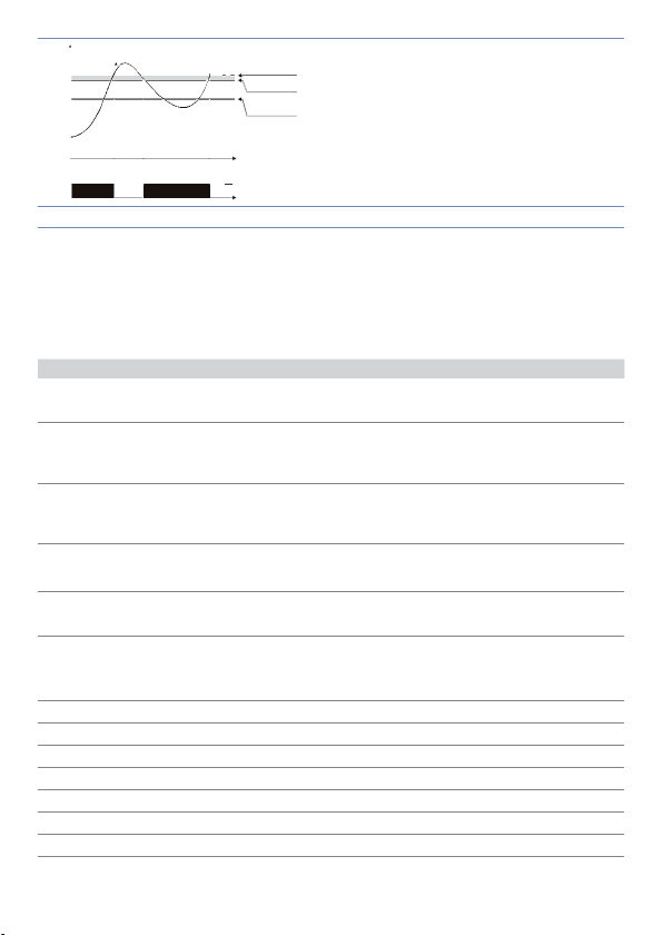
Pv
Hysteresis
Comand Spv
Comand Spv
Comand Spv
Comand Spv
Alarm Spv
Alarm Spv
parameter
> 0
Alarm Spv
Lower deviation alarm value of alarm setpoint
2
On On
O O
** Th e example refer s to alarm 1; the function c an also be enabled fo r alarms 2 and 3 on mod els that include
it. b) With hystere sis value less than “0 ” (
Comand Spv
less than “0” and hysteresis value greater than
“0” (par. 28
Time
Alarm
output
< 0) the broken li ne moves under the al arm setpoint.
A.1. HY.
A.1. HY.
> 0). **
12 Table of Anomaly Signals
If installation malfunctions, controller will switch off regulation output and will report
the anomaly. For example, controller will report failure of a connected thermocouple
visualizing
fl ashing on display for other signals, see table below.
e -05
Cause what to do
E-01
SYS.E
E-02
SYS.E
E-04
SYS.E
E-05
SYS.E
E-08
SYS.E
Error in EEPROM cell
programming.
Call Assistance.
Cold junction sensor fault or
room temperature outside of
Call Assistance.
allowed limits.
Incorrect confi guration data.
Possible loss of calibration
values.
Thermocouple open or
temperature outside of limits.
Check if the confi guration
parameters are correct.
Check the connection with the
sensors and their integrity.
Missing calibration data. Call Assistance.
Notes / Updates
ATR243 - User manual - 45
Page 46

Table of configuration parameters
1
2
3
4
5
6
7
8
9
10
11
12
13
14
15
16
17
18
19
20
21
22
23
24
25
26
27
28
29
30
31
32
33
34
35
36
37
38
39
40
41
42
43
46 - ATR243 - User manual
Command Output 29
C.out
Sensor 31
SEN.
Decimal Point 31
d .P.
Lower Limit Setpoint 31
Lo . L. S.
Upp er Limit Setpoint 31
u p . L.S.
Lower Linear Input 31
Lo L.i
Upper Linear Input 31
u p . L.i .
Latch On Function 32
La t c .
Offset Calibration 32
o . cAL.
Gain Calibration 32
G . cAL.
Action type 32
Act. t.
Command Reset 32
c. re.
Command State Error 32
c. S.e.
Command Led 32
c. Ld.
Command Hysteresis 33
c. HY.
Command Delay 33
c. de.
Command Setpoint Protection 33
c. s. p.
Proportional Band 33
p. b .
Integral T ime 33
t.i .
Derivative Time 33
t.d.
Cycle Time 33
t. c.
Output Power Limit 33
o . P o L.
Alarm 1 34
A L .1
Alarm 1 State Output 34
A.I.5.0
Alarm 1 Reset 34
a1 . r e .
Alarm 1 State Reset 34
a .1 . s . e .
Alarm 1 Led 34
a.1.Ld.
Alarm 1 Hysteresis 34
a .1 . H y .
Alarm 1 Delay 35
a .1 . d e .
Alarm 1 Setpoint Protection 35
a .1 . s p .
Alarm 2 35
AL. 2
Alarm 2 State Output 35
a . 2. s o .
Alarm 2 Reset 35
A2. re.
Alarm 2 State Error 35
a . 2. s . e .
Alarm 2 Led 36
a.2.Ld.
Alarm 2 Hysteresis 36
a.2.HY.
Alarm 2 Delay 36
a.2.d.e.
Alarm 2 Setpoint Protection 36
a . 2. s . p .
Alarm 3 36
AL. 3
Alarm 3 State Output 36
a .3.5. o .
Alarm 3 Reset 37
a .3. re .
Alarm 3 State Error 37
a .3.s . e.
Alarm 3 LED 37
a.3.Ld.
Page 47

44
45
46
47
48
49
50
51
52
53
54
55
56
57
58
59
60
61
62
63
64
65
66
67
68
69
70
71
72
73
Alarm 3 Hysteresis 37
a .3.HY.
Alarm 3 Delay 37
a .3. d e.
Alarm 3 Setpoint Protection 37
a .3.s . p.
Current Transformer 37
t.a.
Loop Break Alarm Threshold 37
L.b.a.t.
Loop Break Alarm Delay 38
L.b.a.d.
Cooling Fluid 38
co o .f.
Proportional Band Multiplier 38
p.b.m.
Overlap / Dead Band 38
oud.b.
Cooling Cycle Time 38
co.t.c.
Conversion Filter 38
c. fLt.
Conversion Frequency 39
c. frn .
Visualization Filter 39
u . FLt .
Tune 39
tun e
Setpoint Deviation Tune 39
s.dtu .
Operating Mode 40
op.mo.
Automatic / Manual 40
au.ma.
Digital Input 40
d G t .i .
Gradient 40
Gra d .
Maintenance Time 40
m a . ti .
User Menu Cycle Programmed 41
u.m.c.p.
Visualization Type 41
ui . tY.
Degree 41
d eG r.
Retransmission 41
re tr.
Lower Limit Retransmission 41
Lo .L. r.
Upper Limit Retransmission 41
up.L.r.
Baud Rate 42
bd . rt.
Slave Address 42
sL. a d .
Serial Delay 42
se. d e.
Lower Limit Output Percentage 42
L.L. o . p.
ATR243 - User manual - 47
Page 48

Introduzione
Grazie per aver scelto un regolatore Omega.
Con il modello CN243 Omega rende disponibile in un singolo strumento tutte le opzioni
relative alla connessione dei sensori e al comando di attuatori, con in aggiunta un’utile
alimentazione a range esteso da 24…230 Vac/Vdc. Con le 18 sonde selezionabili e
l’uscita configurabile come Relè, Comando SSR, 4…20 mA e 0…10 Volt l’utilizzatore o il
rivenditore può gestire al meglio le scorte di magazzino razionalizzando investimento e
disponibilità dei dispositivi.
La serie si co mpleta con i model li dotati di comunica zione seriale RS 485 Modbus Rtu e con
la funzione di controllo del carico tramite trasformatore T.A.
La ripetibilità in serie delle operazioni di parametrizzazione viene semplificata dai CNConfig-Module, dotati di batteria interna che non richiedono cablaggio per alimentare
il regolatore.
1 Norme di sicurezza
Prima di utilizzare il dispositivo, leggere con attenzione le istruzioni e le misure di
sicurezza contenute in questo manuale. Disconnettere l’alimentazione prima di qualsiasi
intervento sulle connessioni elettriche o settaggi hardware.
L’utilizzo/manutenzione è riservato a personale qualificato ed è da intendersi esclusivamente nel rispetto dei dati tecnici e delle condizioni ambientali dichiarate.
Non gettare le apparecchiature elettriche tra i rifiuti domestici.
Secondo la Direttiva Europea 2002/96/CE, le apparecchiature elettriche esauste devono
essere raccolte separatamente al fine di essere reimpiegate o riciclate in modo ecocompatibile.
2 Identificazione del modello
La serie di regolatori CN243 prevede tre versioni: facendo riferimento alla tabella seguente
è facile risalire al modello desiderato.
Modelli con alimentazione 24…230 Vac/Vdc +/-15% 50/60 Hz – 5,5 VA
CN243- R1F2 2 setp oint, 2 Relè 5 A oppure 1 Relè + 1 Ssr/V/mA
CN243-R1R2F3
CN243- R1R2R 3F4C4
* Modelli co n ingresso per T.A. p er funzione “Lo op Break Alarm”.
3 setpoint, 2 Relè 5 A + 1 Ssr/V/mA + RS485 + trasformatore
amperometrico*
4 setpoint, 3 Relè 5 A + 1 Ssr/V/mA + trasformatore
amperometrico*
48 - CN243 - Manuale d’uso
Page 49

3 Dati tecnici
3.1 Caratteristiche generali
Visualizzatori
Temperatura
di esercizio
Protezione IP65 su frontale (con guarnizione) - IP20 cu stodia e morsetti
Materiale PC ABS UL94VO autoestinguente
Peso 165 g (-20ABC) / 185 g (-21/31ABC)
4 display 0,40 pollici
4 display 0,30 pollici
Temperatura funzionamento 0-45 °C
Umidità 35..95 uR%
3.2 Caratteristiche Hardware
Alimentazione
Ingresso analogico
Uscite relè
Usc ita SSR/ V/mA
Alimentazione a range esteso
24…230 Vac/Vdc ±15% 50/60 HzConsumo: 5.5 VA.
1: AN1 Configurabile
via software. Ingresso:
Termocoppie tipo K, S, R, J.
Compensazione automatica
del giunto freddo da 0.. 50 °C.
Termoresistenze: PT100,
PT500, PT1000, Ni100, PTC1K,
NTC10K (β 3435K, OMEGA),
NTC2252-OMEGA ..
Ingresso V/I: 0-10 V, 0-20 o
4-20 mA, 0-40 mV, T.A. 50
mA 1024 punti su versione
CN243-R1R2F3/R1R2R3F4C4.
Ingresso Pot: 6 KΩ, 150 KΩ.
2 Relè (CN243-R1F2/R1R2F3).
3 Relè (CN243-R1R2R3F4C4).
Configurabili come uscita
comando e allarme.
1 SSR
Normaliz zata 0/4…20mA o
0…10 V ol t.
• Deselezionando relè OUT2
su C N243- R1F2
Configurabili come uscita
comando o ritrasmissione
setpoint o processo.
Tolleranza (25 °C)
+/-0.2% ±1 digit (su F.s.) per
termocoppia, termoresistenza e
V / mA.
Precisione giunto freddo 0.1
°C/°C.
Impedenza:
0-1 0 V: Ri>110 KΩ
0-2 0 mA: Ri<5 Ω
4-2 0 mA: Ri<5 Ω
0- 40 mV: Ri>1 MΩ
Contatti
5 A - 250 V~.
Carico resistivo.
12V / 30mA (min. 10.5 V DC).
Configurabile:
0-1 0 V con 9500 punti +/-0.2%
(s u F.s. )
0-2 0 mA con 7500 punti +/-0.2%
(s u F.s. )
4-2 0 mA con 6000 punti +/-0. 2%
(s u F.s. )
Manuale d’uso CN243 - 49
Page 50
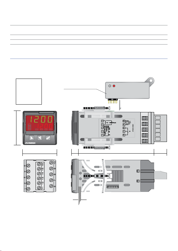
3.3 Caratteristiche Software
15
1116
234
12131415
1 6
12
3
4
5
11 13 14 15 1612
6 7 8 9 10
CN1
1 6
DIMA DI
FORATURA
FRONTAL PANEL
CUT-OUT
46 X 46 mm
48 mm
48 mm 106.5 mm10.5 18
Suggested thickness / Spessore suggerito 2 ÷ 6 mm
CN-CONFIG-MODULE
(optional)
CN-CONFIG-MODULE
CN243
Algoritmi
regolazione
Banda
proporzionale
Tempo integrale 0,0...999,9 sec. (0 esclude funzione integrale)
Tempo derivativo 0,0...999,9 sec. (0 esclude funzione derivativa)
Funzioni del
regolatore
ON-OFF con isteresi.
P, P.I., P.I.D., P.D. a tempo proporzionale.
0...9999 °C o °F
Tuning manuale o automatico allarme selezionabile, protezione
set comando e allarme, selezione funzioni da ingresso digitale,
ciclo pre-programmato con Star t / Stop.
4 Dimensioni ed installazione
50 - CN243 - Manuale d’uso
Page 51
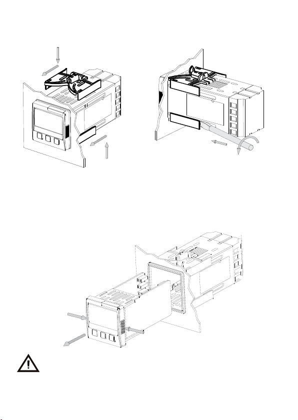
4.1 Montaggio a pannello
1
2
2
1
Modalità di montaggio a pannello, e
fi ssaggio per ganci di ancoraggio.
1
Per lo smontaggio utilizzare un cacciavite
e forzare leggermente i ganci di fi ssaggio
per farli uscire dalla guida di ancoraggio.
2
4.2 Estrazione dell’elettronica
Per estrarre l’elettronica impugnare la parte frontale nelle due apposite zigrinature
laterali.
1
1
2
Prima di eff ettuare qualsiasi operazione di confi gurazione o di manutenzione,
disinserire l’apparecchio dalla rete.
Manuale d’uso CN243 - 51
Page 52
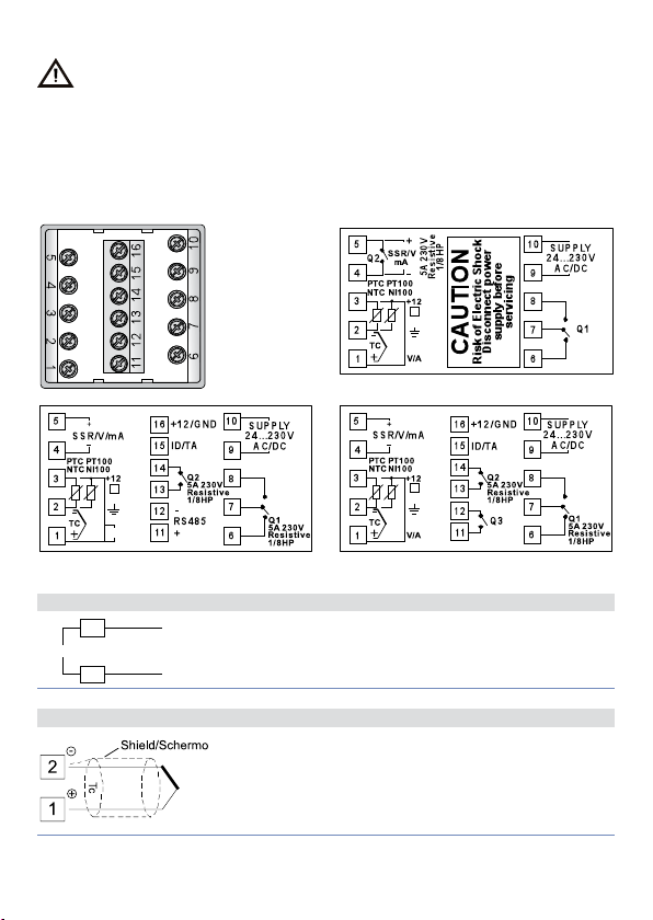
5 Collegamenti elettrici
SUPPLY
Benché questo regolatore sia stato progettato per resistere ai più gravosi disturbi
presenti in ambienti industriali è buona norma seguire la seguenti precauzioni:
• Distinguere la linea di alimentazioni da quelle di potenza.
• Evitare la vicinanza di gruppi di teleruttori, contattori elettromagnetici, motori di
grossa potenza e comunque usare gli appositi filtri.
• Evitare la vicinanza di gruppi di potenza, in particolare se a controllo di fase.
5.1 Schema di collegamento
Di seguito sono riportati i collegamenti dei tre modelli disponibili.
CN243-R1F2
V/I
CN243-R1R2F3 CN243-R1R2R3F4C4
5.1. a Alimentazione
10
24...230V
AC/DC
9
Alimentazione switching a range esteso
24…230 Vac/dc ±15% 50/60 Hz – 5,5 VA
(con isolamento galvanico).
5.1. b Ingresso analogico AN1
52 - CN243 - Manuale d’uso
Per termocoppie K, S, R, J.
• Rispettare la polarità.
• Per eventuali prolunghe utilizzare cavo compensato e
morsetti adatti alla termocoppia utilizzata (compensati).
• Quando si usa il cavo schermato, la schermatura va
collegata a terra ad una sola estremità
Page 53
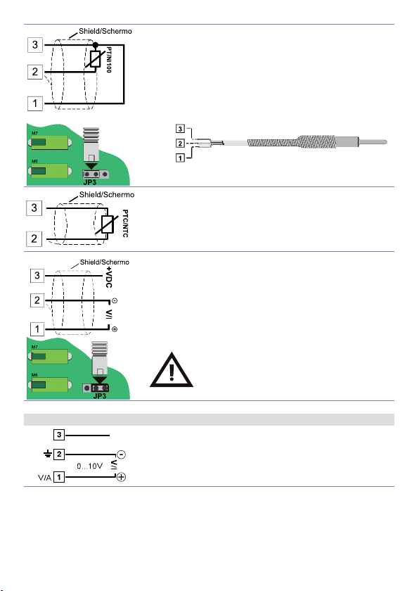
Rosso
+12 V
Red
Bianco
White
Rosso
Red
Per termoresistenze PT100, NI100.
• Per i l collegamento a tre fi li usare cavi dell a stessa sezione.
• Per il collegamento a due fi li cor tocircuitare i morsetti 1 e
3.
• Quando si usa il cavo schermato, la schermatura va
collegata a terra ad una sola estremità
• Selezionare il jumper interno JP3 come in fi gura.
ROSSO
BIANCO
ROSSO
Per termoresistenze NTC, PTC , PT500, PT1000 e
potenziometri lineari.
Quando si usa il cavo schermato, la schermatura va
collegata a terra ad una sola estremità
Per segnali normaliz zati in corrente e tensione.
Rispettare la polarità.
Quando si usa il cavo schermato, la schermatura va
collegata a terra ad una sola estremità
Selezionare il jumper interno JP3 come in fi gura.
In mancanza della corretta selezione dei
Jumper non saranno disponibili i 12 Vdc / 30
mA sul morsetto numero 3 per
l’alimentazione del sensore.
5.1. c Esempi di collegamento per ingressi Volt e mA
30 mA
Per segnali normaliz zati in tensione 0…10 V.
Rispettare le polarità.
Manuale d’uso CN243 - 53
Page 54
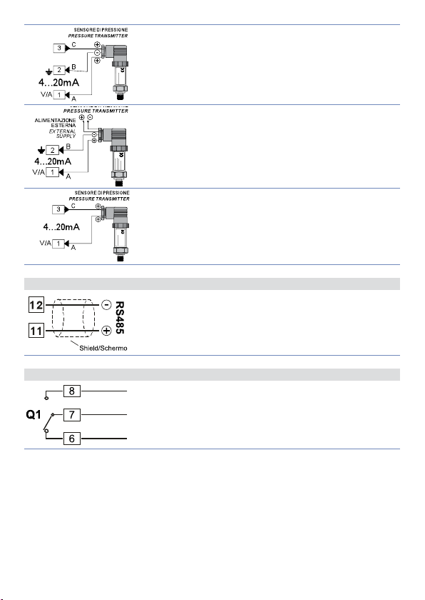
+12 V
30 mA
+12 V
30 mA
5.1. d Ingresso seriale
5.1. e Uscita Relè Q1
Per segnali normaliz zati in corrente 0/4….20 mA con
sensore a tre fi li.
Rispettare le polarità:
A= Uscita sensore
B= Massa sensore
C= Alimentazione sensore (+12Vdc / 30mA)
Per segnali normaliz zati in corrente 0/4….20 mA con
sensore ad alimentazione esterna.
Rispettare le polarità:
A= Uscita sensore
B= Massa sensore
Per segnali normaliz zati in corrente 0/4….20 mA con
sensore a due fi li.
Rispettare le polarità:
A= Uscita sensore
C= Alimentazione sensore (+12Vdc / 30mA)
Comunicazione RS485 Modbus RTU.
Portata contatti 5 A / 250 V~ per carichi resistivi.
NB: vedi grafi co nella pagina successiva.
54 - CN243 - Manuale d’uso
Page 55
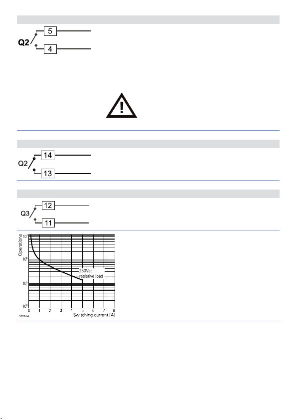
5.1. f Uscita Relè Q2 per CN243-R1F2
Portata contatti 5 A / 250 V~ per carichi resistivi.
Per selezionare Q2 come uscita relè, verificare che non
siano inseriti i jumper JP5 e JP7.
NB: vedi grafico nella pagina successiva.
Connettere un carico senza togliere i
Jumper danneggia il regolatore.
5.1. g Uscita Relè Q2 per CN243-R1R2F3 e CN243-R1R2R3F4C4
Portata contatti 5 A / 250 V~ per carichi resistivi.
NB: vedi grafico nella pagina successiva.
5.1. h Uscita Relè Q3 su CN243-R1R2R3F4C4
Portata contatti 5 A / 250 V~ per carichi resistivi.
NB: vedi grafico qui sotto.
Electrical endurance
Q1 / Q2 / Q3:
5 A, 250 Vac, carico resistivo, 105 operazioni.
20/2 A, 250 Vac, cosφ = 0.3, 105 operazioni.
Manuale d’uso CN243 - 55
Page 56
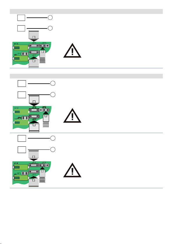
5.1. i Uscita SSR
5
SSR
4
+
-
5.1. j Uscita mA / Volt
5
+
mA
4
-
Uscita comando SSR portata 12 V / 30 mA (min. 10.5 V
DC).
Inserire JP5 e JP7 e selezionare J P9 come in
fi gura per utilizzare l’uscita SSR.
Uscita continua in mA confi gurabile da parametri
come comando (parametro
processo-setpoint (parametro
Inserire JP5 e JP7 e selezionare J P9 come in
fi gura per utiliz zare l’uscita continua in mA
(Jumpers forniti all’interno della
confezione).
) o ritrasmissione del
c.out
)
rE t r.
5
V
4
56 - CN243 - Manuale d’uso
+
Uscita continua in Volt confi gurabile da parametri
come comando (parametro
-
processo-setpoint (parametro
Inserire JP5 e JP7 e selezionare J P9 come in
fi gura per utiliz zare l’uscita continua in
Volt (Jumpers forniti all’interno della
confezione).
) o ritrasmissione del
c.out
)
rE t r.
Page 57
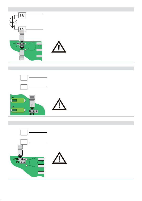
5.1. k Ingresso T.A. su CN243-R1R2F3 e CN243-R1R2R3F4C4
• Ingresso per trasformatore amperometrico 50mA
(risoluzione 1024 punti).
• Tempo di campionamento 80 ms.
• Confi gurabile da parametri.
Inserire JP4 e JP6 come in fi gura per
selezionare l’ingresso T.A.
5.1. l Ingresso digitale su CN243-R1F2
+ 12V
3
GND
I D
2
Ingresso digitale (parametro
L’utilizzo dell’ingresso digitale in questa versione è
possibile solo con sonde tipo Tc, 0…10 V, 0/4…20 mA e
0…40 mV.
Inserire JP3 come in fi gura per selezionare
l’ingresso digitale.
d G ti
.).
5.1. m Ingresso digitale su CN243-R1R2F3 e CN243-R1R2R3F4C4
+ 12V
16
GND
I D
15
Ingresso digitale da parametro
d G ti
.
Inserire JP4 come in fi gura per selezionare
l’ingresso digitale.
Manuale d’uso CN243 - 57
Page 58
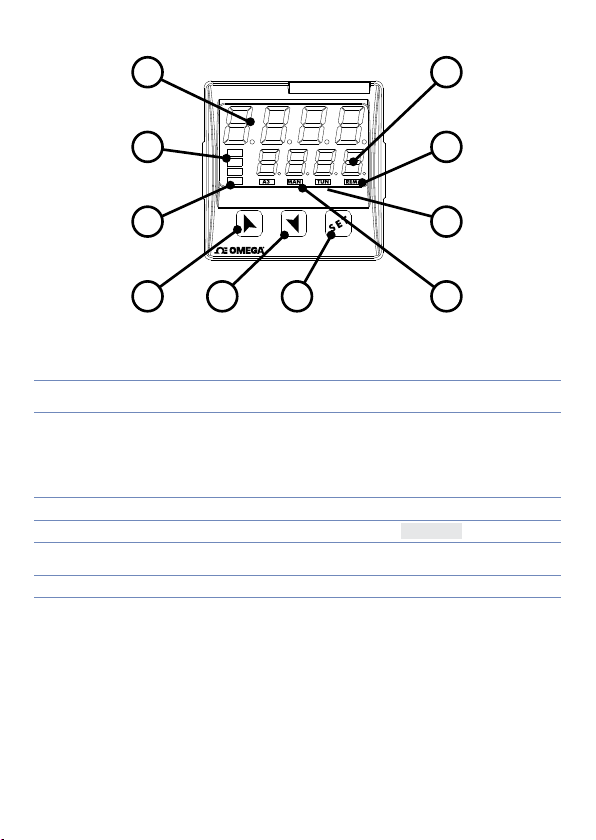
6 Funzione dei visualizzatori e tasti
1
CN243
2
3
4
8 9
C1
C2
A1
A2
10
7
6
5
6.1 Indicatori numerici (Display)
1
1234
2
1234
Normalmente visualizza il processo. In fase di configurazione
visualizza il parametro in inserimento.
Normalmente visualizza i setpoint. In fase di configurazione
visualizza il valore del parametro in inserimento.
6.2 Significato delle spie di stato (Led)
3 C1 C2
4 A1 A2 A3 Si accendono quando l’allarme corrispondente è attivo.
5 MAN
6 TUN
7 REM Si accende quando il regolatore comunica via seriale.
Si accendono quando l’uscita comando è attiva. C1 con comando
relè/SSR/mA/Volt o C1 (apri) e C2 (chiudi) nel caso di comando
valvola motorizzata.
Si accende all’attivazione della funzione “Manuale”.
Si accende quando il regolatore sta eseguendo un ciclo di
AutoTuning.
58 - CN243 - Manuale d’uso
Page 59
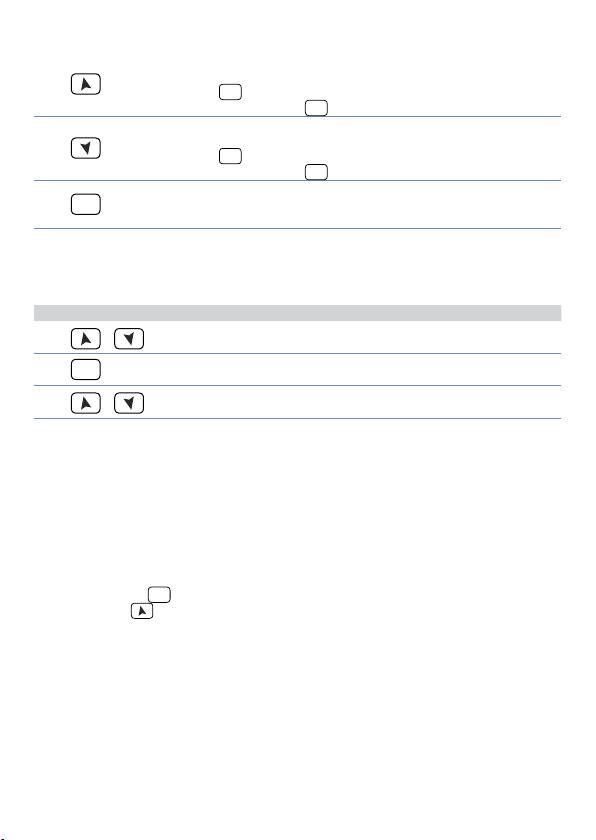
6.3 Tas t i
• Incrementa il setpoint principale.
8
9
SET
10
• In f ase di configurazion e consente di scorrere i p arametri. Insiem e
• Premuto dopo il tasto
• Decrementa il setpoint principale.
• In f ase di configurazion e consente di scorrere i p arametri. Insiem e
• Premuto dopo il tasto
Permette di visualizzare i setpoint di allarme e di entrare nella
funzione di lancio del Tuning.
Permette di variare i parametri di configurazione.
al tasto
al tasto
SET
li modifica.
SET
li modifica.
SET
incrementa i setpoint di allarme.
SET
decrementa i setpoint di allarme.
7 Funzioni del regolatore
7.1 Modifica valore setpoint principale e setpoint di allarme
Il valore dei setpoint può essere modificato da tastiera come segue:
Premere Effetto Eseguire
1
2
3
o
SET
o
La cifra sul display 2 varia.
Visualizza setpoint di allarme
sul display 1.
La cifra sul display 2 varia.
Incrementare o diminuire il
valore del setpoint principale.
Incrementare o diminuire il
valore del setpoint di allarme.
7. 2 Auto-Tuning
La procedura di Tuning per il calcolo dei parametri di regolazione può essere manuale o
automatica e viene selezionata da parametro 57 (
tunE
).
7. 3 Lancio del Tuning Manuale
La procedura manuale permette all’utente maggiore flessibilità nel decidere quando
aggiornare i parametri di regolazione dell’argoritmo P.I.D.. La procedura può essere
attivata in due modi.
• Lancio del Tuning da tastiera:
Premere il tasto
, premere , il display 2 visualizza on.
o FF
Il led TUN si accende e la procedura ha inizio.
• Lancio del Tuning da ingresso digitale:
Selezionare
(commutazione su fronte) il led TUN si accende, alla seconda si spegne.
SET
finché il display 1 non visualizza la scritta
su parametro 61
tunE
. Alla prima attivazione dell’ingresso digitale
d G t.i
con il display 2 su
tunE
Manuale d’uso CN243 - 59
Page 60

7.4 Lancio del Tuning Automatico
Il Tuning automatico si attiva all’accensione dello strumento o quando viene modificato il
setpoint di un valore superiore al 35%.
Per evitare overshoot, il punto dove il regolatore calcola i nuovi parametri PID è
determinato dal valore di setpoint meno il valore “Set Deviation Tune” (vedere parametro
).
58
S.D. t u .
Per interrompere il Tuning lasciando invariati i valori PID, premere il tasto
display 1 non visualizza la scrit ta
2 visualizza
, il led TUN si spegne e la procedura termina.
o FF
e il display 2 visualizz a on. Premendo , il display
tun e
SET
finché il
7. 5 Soft-Start
All’accensione il regolatore per raggiungere il setpoint segue un gradiente di salita
impostato in Unità (es. Grado / Ora). Impostare sul parametro 62
incremento desiderato in Unità/Ora; alla successiva accensione lo strumento eseguirà
la funzione Soft-Star t. Se il parametro 59
è diverso da 0, dopo l’accensione, trascorso il tempo impostato sul parametro 63,
m a . ti .
il setpoint non segue più il gradiente, ma si por ta alla massima potenza verso il setpoint
finale.
L’autotuning non funziona mai quando solo il par.
è diverso da 0 e il parametro 57
63
m a . ti .
allo scadere del tempo di Soft-Start, mentre se il parametro 57
funzione può essere lanciata solamente allo scadere del Soft-Start.
è impostato su
op.mo.
è impostato su
tun e
co nt.
è diverso da 0. Se il parametro
GrAd .
Auto
tun e
il valore di
GrAd .
e il parametro 63
, l’autotuning parte
è impostato
Man.
la
7.6 Regolazione automatico / manuale per controllo % uscita
Questa funzione permette di passare dal funzionamento automatico al comando manuale
della percentuale dell’uscita.
Con il parametro 60
1 La prima selezione (
display 1, mentre sul display due appare
Premere il tasto per visualizzare
del processo, variare con i tasti
automatico, con la stessa procedura, selezionare
led TUN e il funzionamento torna in automatico.
2 La seconda selezione (
varianti:
• Nel caso di temporanea mancanza di tensione o comunque dopo uno spegnimento,
accendendo il regolatore, verrà mantenuto sia il funzionamento in manuale, sia il
valore di percentuale dell’uscita precedentemente impostato.
• Nel caso di rottura del sensore durante il funzionamento automatico, il regolatore si
porterà in manuale mantenendo invariata la percentuale di uscita comando generata
dal P.I.D. subito prima della rottura.
Es: su un e strusore viene mant enuto il comando in percentuale della resistenz a (carico)
anche nel caso di guasto sulla sonda in ingresso.
è possibile selezionare due modalità.
Au.m a.
) permette di abilitare con il tasto
en.
) abilita lo s tesso funzionamento, ma con due importanti
en.st.
au to.
; è ora possibile, durante la visualizzazione
man,
e la percentuale dell’uscita. Per tornare in
SET
la scritta
sul display 2: subito si spegne il
au to
p.---
sul
60 - CN243 - Manuale d’uso
Page 61
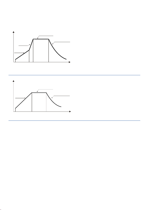
7.7 Ciclo pre-programmato
La funzione ciclo pre-programmato si abilita impostando
parametro 59
oP.Mo
.
Prima selezione (
il regolatore raggiunge il setpoint 1
seguendo il gradiente impostato nel
parametro 62
potenza verso il setpoint 2. Quando il
Gra d .
processo lo raggiunge, lo mantiene per
il tempo impostato nel parametro 63
Allo scadere, l’uscita di comando è
m a . ti .
disabilitata e lo strumento visualizza
La partenza del ciclo avviene al ogni
Tempo
accensione dello strumento, oppure da
Setpoint
Gradiente
Setpoint 2
Max.
potenza
Setpoint 1
Mantenimento
Rareddamento
naturale
ingresso digitale se abilitato per questo
funzionamento (vedi parametro 61
Seconda selezione (
la partenza è decisa solo dall’attivazione
Setpoint
Gradiente
Setpoint 1
Mantenimento
Rareddamento
naturale
dell’ingresso digitale, a prescindere
dall’impostazione del parametro 61
Alla partenza, il regolatore raggiunge il
setpoint 1 seguendo il gradiente impostato
nel parametro 62
lo raggiunge, lo mantiene per il tempo
impostato nel parametro 63
Tempo
Allo scadere, l’uscita di comando è
disabilitata e lo strumento visualizza
Variante (
Selezionando
(
Pr. cy
strumento regola la potenza dell’uscita al valore percentuale impostato sul parametro
62
GrAd .
Quando il processo supera il SET1 o è trascorso il tempo impostato sul parametro 63
, il regolatore porta il processo al SET2 alla massima potenza e lo mantiene per un
M A . ti .
tempo infi nito.
Se sul parametro 59
17
c. S . P.
diventa semplicemente SET. In questa modalità, lanciando il tune manuale durante
):
S.S. cY.
) con due importanti varianti. Se all’accensione il processo è inferiore al SET1, lo
(Soft Star t Cycle) il regolatore si comp orta come nell a prima selezio ne
S.S. cY.
è impostato
: in questo modo non viene più visualizzato il SET1, mentre la label del SET2
oP.Mo.
è possibile selezionare
S.S. cY.
la regolazione sul SET1 non si vedrà accendersi il led TUN fi nchè non si passerà alla
regolazione sul SET2.
L’autotuning (automatico e manuale) funziona, ma solo se sta regolando sul SET2. Se
viene lanciato durante la regolazione sul SET1, rimane in standby per poi partire appena
si passa alla regolazione sul SET2.
oppure
Pr. cy
Pr. cy
):
Pc. SS.
, poi sale alla massima
d G t.i .
):
p.c.s.s.
Quando il processo
Gra d .
m a . t.i .
sul parametro
Hi d E
stop
d G t.i .
stop
nel
.
).
.
Manuale d’uso CN243 - 61
Page 62
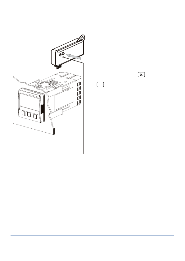
7.8 CN-Config-Module (opzionale)
È possibile duplicare parametri e setpoint da un regolatore ad un altro mediante l’uso del
CN-Config-Module.
Sono previste due modalità:
• Con regolatore connesso all’alimenta-
zione:
Inserire il CN-Config-Module con
regolatore spento. All’accensione il
display 1 visualizza
visualizza
Module sono salvati valori corretti).
Premendo il tasto
visualizza
SET
. Il regolatore carica i nuovi valori e
(solo se nel CN-Config-
----
. Confermare con il tasto
Lo a d
riparte.
• Con regolatore non connesso all’ali-
mentazione:
Il CN- Config-Module è dotato di
batteria interna con autonomia per circa
1000 utilizzi (batteria a bottone 2032,
sostituibile). Inserire il CN-Config-Module
e premere il tasto di programmazione.
LED ROSSO: acceso in programmazione
Red Light: waiting for programming
LED VERDE: programmazione eseguita
Green Light: done
Durante la scrittura dei parametri il led si
accende ross o, al termine della pr ocedura
si accende verde. E’ possibile ripetere la
procedura senza particolari attenzioni.
NB: non è possibile trasferire i parametri di uno strumento ad uno con codice differente:
il LED rimane acceso rosso.
Aggiornamento CN-Config-Module.
Per aggiornare i valori del CN-Config-Module seguire il procedimento descritto nella
prima modalità, impostando
regolatore
1
. Entrare in configurazione e variare almeno un parametro. Uscendo dalla
sul display 2 in modo da non caricare i parametri sul
----
configurazione il salvataggio sarà automatico.
e il display 2
mem o
il display 2
1
Nel caso in cui al l’accensione il regolator e non visualizzi
CN-Config-Module, ma è possibile ugualmente aggiornarne i valori.
62 - CN243 - Manuale d’uso
significa che n on ci sono dati salvati nel
mem o
Page 63
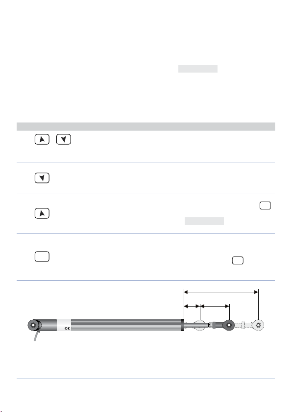
7.9 Funzione Latch on
Max
Per l’impie go con ingresso
(0…10 V, 0...40 mV, 0/4…20 mA), è possibile associare il valore di inizio scala (parametro 6
) alla posizione di minimo del sensore e quello di fi ne scala (parametro 7
Lo L.i
posizione di massimo del sensore (parametro 8
possibile fi ssare il punto in cui lo strumento visualizzerà 0 (mantenendo comunque il campo
scala compreso tra
oppure
u.in.
dopo ogni accensione dello strumento; se si imposta
volta tarato. Impostando “
superiore se in ingresso ci sono valori esterni al 0/4…20mA o 0…10V.
Per utilizzare la funzione LATCH ON confi gurare come desiderato il parametro
procedura di taratura fare riferimento alla seguente tabella:
1
contemporaneamente
2
3
SET
4
Lo L.i
nel parametro 8
Premere E ff e t t o Eseguire
+
(pot. 6 KΩ) e
P o t .1
e
) tramite l’opzione di “zero virtuale” impostando
u P.L.i
Se si imposta
La t c .
” (dynamic limits) permette di superare i limiti inferiore e
dYn .L
Esce dalla confi gurazione
parametri. Il display 2
visualizza la scritta
Fissa il valore sul minimo.
Il display visualizza
Fissa il valore sul massimo.
Il display visualizza
Fissa il valore di zero vir tuale.
Il display visualizza
NB: nel caso di selezione
la procedura al
u.0.in.
punto 4 va eseguita ad ogni
ri-accensione.
(pot. 150 KΩ) e con ingressi normalizzati
Po t.2
confi gurato come
La t c .
lo zero virtuale andrà reimpostato
u.in.
lo zero virtuale resterà fi sso una
u .St.
Posizionare il sensore
sul valore minimo di
funzionamento (associato a
.
LA t c
Lo
Hi G H
ui r t .
.
.
).
Lo L.i .
Posizionare il sensore
sul valore massimo di
funzionamento (associato a
).
u p . L.i .
Per uscire dalla procedura
standard tenere premuto
Nel caso di impostazione con
“zero virtuale” posizionare il
sensore nel punto di zero.
Per uscire dalla procedura
tenere premuto
u P.L.i
). È inoltre
Std .
LA t c
SET
.
) alla
u .St.
2
. Per la
SET
Min Zero
.
2
La procedura d i taratura parte uscen do dalla confi gurazione do po aver variato il para metro.
Manuale d’uso CN243 - 63
Page 64

7.10 Loop Break Alarm da ingresso T.A. (Trasformatore Amp.)
Permette di misurare la corrente sul carico per gestire un allarme in caso di malfunzionamento (con stadio di potenza in corto oppure sempre aperto). Il trasformatore
amperometrico collegato ai morsetti 15 e 16 deve essere da 50 mA (tempo di
campionamento 80 ms).
• Impostare sul parametro 47
amperometrico.
• Impostare sul parametro 48
Alarm.
• Impostare sul parametro 49
Alarm.
• è possibile associare l’allarme ad un relè, impostando il parametro
come
AL. 3
Nel caso un te leruttore o relè all o stato solido dovesse restare sempre chiuso il regolatore
segnala il guasto visualizzando
comando).
Nel caso invece lo stadio di potenza dovesse restare sempre aperto, oppure la corrente
sul carico fosse inferiore al valore impostato su
2
L.b.a.o.
potenza.
1
Impostando sul parametro 48
assorbita senza mai generare il Loop Break Alarm.
L.b.a.
È possibile visualizzare la corrente assorbita in fase di chiusura dello stadio di
Premere Effetto Eseguire
SET
il valore di fondo scala in Ampere del trasformatore
t.a .
la soglia di intervento in Ampere del Loop Break
L.b.a.t.
il tempo di ritardo per l’intervento del Loop Break
L.b.a.d.
AL. 1, AL. 2
sul display 2 (alternativamente con il setpoint di
L.b.a.c.
, il regolatore visualiz za sul display
L.b.a.t.
SET
Questo tasto, in modo ciclico,
permette di visualizzare
sul display 2 percentuale di
uscita, selezione auto / man,
setpoint ed allarmi.
il valore 0 è possibile visualizzare la corrente
L.b.A.t.
Premere
visualizzazione sul display
1 della scritta
display 2 della corrente in
Ampere (
t.a .
è mantenuto anche quando
non circola corrente sul carico.
fino alla
e sul
am.t.a.
>0). Il valore
oppure
7.11 Funzioni da Ingresso digitale
Il CN243 integra alcune funzionalità relative all’ingresso digitale, che può essere abilitato
utilizz ando i parametri 59
• Parametro 59
NB: Utilizzando le seguenti impostazioni, il parametro 61
2t.s .
contatto chiuso regola su SET2;
2 t. s .i.
agendo con un impulso sull’ingresso digitale;
3 t. s.i .
4 t. s .i .
t. res .
p.c.s.s.
I vari setpoint possono essere impostati durante il funzionamento premendo
64 - CN243 - Manuale d’uso
op.mo.
: Cambio setpoint a due soglie: con contatto aperto il CN243 regola su SET1; con
: Cambio setpoint a due soglie: la selezione del punto di lavoro viene fatta
: Cambio setpoint a tre soglie con impulso sull’ingresso digitale;
: Cambio setpoint a quattro soglie con impulso sull’ingresso digitale;
: Funzione personalizzata;
: Ciclo pre-programmato (Vedi pa ragrafo 7.7).
op.mo.
e 61
d G t.i .
viene ignorato.
d G t.i .
SET
.
Page 65

• Parametro 61
NB: Le impostazioni su questo parametro sono considerate solo impostando
oppure
st. st.
da start a stop;
rn.n.o.
rn.n.c.
L.c.n.o.
Lc.n . c.
tun e
a.ma.i.
passa alternativamente da regolazione automatica a regolazione manuale;
a.ma.c.
con ingresso aperto e in manuale con ingresso chiuso.
NB: le funzioni da ingresso digitale NON sono disponibili con sonde di tipo resistivo sul
modello CN243-R1F2.
d G t.i .
man.
co nt.
;
sul parametro 59
p r. cY.
: Start / Stop; agendo sull’ingresso digitale il regolatore passa alternativamente
: Run N.O. Il regolatore è in start solamente con ingresso chiuso;
: Run N.C. Il regolatore è in start solamente con ingresso aperto;
: Con ingresso chiuso blocca la lettura delle sonde;
: Con ingresso aperto blocca la lettura delle sonde;
: Abilita/disabilita il Tuning se il parametro 57
: Se par. 60
: Se par. 60
au.ma.
au.ma.
op.mo.
è imposta to su
è impostato su
en.
è impostato su
tun e
o
agendo sull’ingresso il regolatore
en.st.
o
en.
. Il CN243 regola in automatico
en.st.
7.12 Funzionamento in doppia azione (caldo / freddo)
Il CN243 è adatto alla regolazione anche su impianti che prevedano un’azione combinata
caldo-freddo.
L’uscita di comando deve essere configurata in P.I.D. caldo
=
e
(
Act. t.
HEAT
configurato come
L’uscita di comando va collegata all’attuatore responsabile dell’azione caldo, l’allarme
comanderà invece l’azione refrigerante.
I parametri da configurare per il P.I.D. caldo sono:
=
Act. t.
HEAT
: Banda proporzionale azione caldo;
P. b .
: Tempo integrale azione caldo ed azione freddo;
t.i
: Tempo derivativo azione caldo ed azione freddo;
t.d .
: Tempo di ciclo azione caldo.
t. c.
I parametri da configurare per il P.I.D. freddo sono (azione associata, per esempio,
all’allarme 1):
=
A L .1
coo L
: Moltiplicatore di banda proporzionale;
P. b . M .
: Sovrapposizione / Banda mor ta;
ou.d.b.
: Tempo di ciclo azione freddo.
co.t.c.
Il parametro
refrigerante secondo la formula:
Banda proporzionale azione refrigerante =
Si avrà così una banda proporzionale per l’azione refrigerante che sarà uguale a quella
dell’azione caldo se
Tempo integrale e Tempo derivativo sono gli stessi per entrambe le azioni.
Il parametro
gli impianti in cui l’uscita riscaldante e l’uscita refrigerante non devono mai essere attive
contemporaneamente si configurerà una Banda morta
configurare una sovrapposizione (
maggiore d i 0), e uno degli all armi (
P. b .
.
coo L
Tipo azione uscita di comando (Caldo);
Selezione allarme 1 (Freddo);
(che varia da 1.00 a 5.0 0) determina la band a proporzionale d ell’azione
p.b.m.
P. b . x P. b . M .
= 1.00, o 5 volte più grande se
P. b . M .
determina la sovrapposizione in percentuale tra le due azioni. Per
ou.d.b.
> 0).
ou.d.b.
A L .1, AL. 2
P. b . M .
ou.d.b.
oppure
= 5.00.
≤ 0), viceversa si potrà
) deve essere
AL. 3
Manuale d’uso CN243 - 65
Page 66
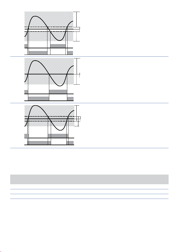
SPV
x = COOL
ALARM OUTPUT (COOL)
ACTIVE
ACTIVE
SPV
PV
x = COOL
< 0
(HEAT)
COMMAND OUTPUT (HEAT)
ALARM OUTPUT (COOL)
ALARM OUTPUT (COOL)
SPV
ACTIVE
ACTIVE
SPV
PV
x = COOL
x = COOL
< 0
= 0
(HEAT)
(HEAT)
COMMAND OUTPUT (HEAT)
ALARM OUTPUT (COOL)
COMMAND OUTPUT (HEAT)
ALARM OUTPUT (COOL)
SPV
PV
ACTIVE
ACTIVE
1
PV
ACTIVE
ACTIVE
< 0
(HEAT)
COMMAND OUTPUT (HEAT)
x = COOL
2
PV
ACTIVE
SPV
3
PV
ACTIVE
Il parametro
parametro
proporzionale
refrigerante:
c o o . F.
Ai r
oi L
H2o
Una volta selezionato il parametro
essere comunque modificati.
66 - CN243 - Manuale d’uso
ha lo stesso significato del tempo di ciclo per l’azione caldo
co.t.c.
(fluido di raffreddamento) pre-seleziona il moltiplicatore di banda
co o . f.
ed il tempo di ciclo
P. b . M .
Tipo di fluido
= 0
(HEAT)
ACTIVE
ACTIVE
refrigerante
Aria 1.00 10
Olio 1.25 4
Acqua 2.50 2
COMMAND OUTPUT (HEAT)
x = COOL
> 0
(HEAT)
COMMAND OUTPUT (HEAT)
ALARM OUTPUT (COOL)
del P.I.D. freddo in base al tipo di fluido
co.t.c.
P. b .M . co.t.c
, i parametri
co o . f.
P. b . M ., oud.b.
e
co.t.c.
Il
t. c.
possono
Page 67

8 Comunicazione Seriale
Il CN243-R1R2F3 con RS485 può ricevere e trasmettere dati via seriale tramite protocollo
MODBUS RTU. Il dispositivo può essere configurato solo come Slave. Questa funzione
permette il controllo di più regolatori collegati ad un sistema di supervisione. Ciascuno
strumento risponderà ad un’interrogazione del Master solo se questa contiene l’indirizzo
uguale a quello contenuto nel parametro
Gli indirizzi permessi vanno da 1 a 254 e non devono esserci regolatori con lo stesso
indiriz zo sulla stessa linea . L’ind irizzo 255 può essere u sato dal Master per comu nicare con
tutte le apparecchiature collegate (modalità broadcast), mentre con 0 tutti i dispositivi
ricevono il comando, ma non è prevista alcuna risposta.
Il CN243 può introdurre un ritardo (in millisecondi) della risposta alla richiesta del
Master. Tale ritardo deve essere impostato sul parametro 72
dei parametri lo strumento salva il valore in memoria EEPROM (100000 cicli di scrittura),
mentre il salvataggio dei setpoint avviene con un ritardo di 10 secondi dall’ultima
modifica.
NB: modifiche apportate a Word diverse da quelle riportate nella tabella seguente
possono causare mal funzionamenti dello strumento.
Caratteristiche protocollo Modbus RTU
Baud-rate
Formato 8, N, 1 (8 bit, no parità, 1 stop)
Funzioni supportati
Si riporta di seguito l’elenco di tutti gli indirizzi disponibili e le funzioni supportate:
RO Read Only R/W Read / Write WO Write Only
SL. Ad .
Ad ogni variazione
se. d e.
Selezionabile da parametro 70
4.800 bit/Sec.
4.8 k
9.600 bit/Sec.
9.6 k
19.200 bit/Sec.
19.2k
28.800 bit/Sec.
28.8 k
38.400 bit/Sec.
38 .4 k
57.600 bit/Sec.
57.6 k
WORD READING (max 20 word) (0x03, 0x04)
SINGLE WORD WRITING (0x06)
MULTIPLE WORDS WRITING (max 20 word) (0x10)
bd . rt.
:
Modbus
Address
0 Tipo dispositivo RO EEPROM
1 Versione software RO EEPROM
5 Address slave R/W EEPROM
6 Versione boot RO EEPROM
50 Indirizzamento automatico WO 51 Confronto codice impianto WO -
500 Caricamento valori di default (scrivere 9999) R/W 0
510 Tempo salvataggio setpoint in eeprom (0-60 s) R/W 10
999 Processo sottoposto al filtro in visualizzazione RO -
Descrizione
Read
Only
Manuale d’uso CN243 - 67
Reset
value
Page 68

Modbus
Address
Processo (gradi con decimo per sensori di temperatura;
1000
digit per sensori normalizzati)
Descrizione
Read
Only
RO -
1001 Setpoint 1 R/W EEPROM
1002 Setpoint 2 R/W EEPROM
1003 Setpoint 3 R/W EEPROM
100 4 Setpoint 4 R/W EEPROM
1005 Allarme 1 R/W EEPROM
1006 Allarme 2 R/W EEPROM
1007 Allarme 3 R/W EEPROM
1008 Setpoint gradiente RO EEPROM
Stato relè (0 = Off, 1 = On):
Bit 0 = Relè Q1
1009
Bit 1 = Relè Q2
RO 0
Bit 2 = Riser vato
Bit 3 = SSR
1010 Percentuale uscita caldo (0-10000) RO 0
1011 Percentuale uscita freddo (0 -10000) RO 0
Stato allarmi (0 = A ssente, 1 = Presente)
1012
Bit 0 = Allarme 1 Bit 1 = Allarme 2 Bit 2 = Allarme 3
RO 0
Riarmo manuale: scrivere 0 per riarmare tutti gli allarmi.
1013
In lettura (0 = Non riarmabile, 1 = Riarmabile)
WO 0
Bit 0 = Allarme 1 Bit 1 = Allarme 2 Bit 2 = Allarme 3
Flags errori
Bit 0 = Errore scrittura eeprom
Bit 1 = Errore lettura eeprom
Bit 2 = Errore giunto freddo
Bit 3 = Errore processo (sonda)
1014
Bit 4 = Errore generico
RO 0
Bit 5 = Errore hardware
Bit 6 = Errore L.B.A.O.
Bit 7 = Errore L.B.A.C.
Bit 8 = Errore tarature mancanti
1015 Temperatura giunto freddo (gradi. decimi) RO -
Start / Stop
1016
0 = regolatore in STOP 1 = regolatore in START
Lock conversion ON / OFF
1017
0 = Lock conversion off 1 = Lock conversion on
Tuning ON / OFF
1018
0 = Tuning off 1 = Tuning on
Selezione automatico / manuale
1019
0 = Automatico 1 = Manuale
R/W 0
R/W 0
R/W 0
R/W 0
1020 Corrente T.A. ON (ampere con decimo) RO -
1021 Corrente T.A. OFF (ampere con decimo) RO
1022 Tempo OFF LINE* (millisecondi) R/W
68 - CN243 - Manuale d’uso
Reset
value
Page 69

Modbus
Address
1023 Corrente istantanea (Ampere) R/W 0
Descrizione
Read
Only
Reset
value
1024 Stato ingresso digitale R/W 0
Tuning sincronizzato per multizona
0 = Tuning OFF (Funzionamento normale del regolatore)
1 = Uscita comando OFF
1025
2 = Uscita comando ON
R/W 0
3 = Start Tuning
4 = Fine Tuning e comando OFF (Portare la word 1025 al
valore 0)
Processo sottoposto al filtro in visualizz azione e alla
1099
selezione del punto decimale
RO
110 0 Processo con selezione del punto decimale RO
1101 Setpoint 1 con selezione del punto decimale R/W EEPROM
110 2 Setpoint 2 con selezione del punto decimale R/W EEPROM
110 3 Setpoint 3 con selezione del punto decimale R/W EEPROM
110 4 Setpoint 4 con selezione del punto decimale R/W EEPROM
110 5 Allarme 1 con selezione del punto decimale R/W EEPROM
110 6 Allarme 2 con selezione del punto decimale R/W EEPROM
110 7 Allarme 3 con selezione del punto decimale R/W EEPROM
110 8 Setpoint gradiente con sel. del punto decimale RO EEPROM
110 9 Percentuale uscita caldo (0-1000) R/W 0
1110 Percentuale uscita caldo (0-100) RO 0
1111 Percentuale uscita freddo (0 -1000) RO 0
1112 Percentuale uscita freddo (0-100) RO 0
2001 Parametro 1 R/W EEPROM
2002 Parametro 2 R/W EEPROM
2072 Parametro 72 R/W EEPROM
3000 Disabilitazione controllo macchina da seriale** RO 0
3001 Prima word display 1 (ascii) R/W 0
3002 Seconda word display 1 (ascii) R/W 0
3003 Terza word display 1 (ascii) R/W 0
3004 Quarta word display 1 (ascii) R/W 0
3005 Quinta word display 1 (ascii) R/W 0
3006 Sesta word display 1 (ascii) R/W 0
3007 Settima word display 1 (ascii) R/W 0
3008 Ottava word display 1 (ascii) R/W 0
3009 Prima word display 2 (ascii) R/W 0
3010 Seconda word display 2 (ascii) R/W 0
30 11 Terza word display 2 (ascii) R/W 0
3012 Quarta word display 2 (ascii) R/W 0
3013 Quinta word display 2 (ascii) R/W 0
3014 Sesta word display 2 (ascii) R/W 0
3015 Set tima word display 2 (ascii) R/W 0
3016 Ottava word display 2 (ascii) R/W 0
Manuale d’uso CN243 - 69
Page 70
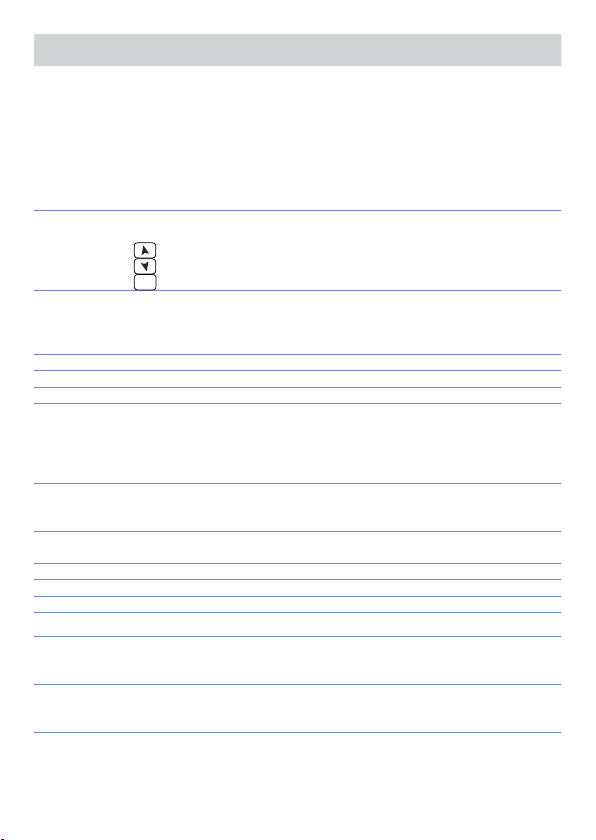
Modbus
Address
Descrizione
Word LED
Read
Only
Reset
value
Bit 0 = LED C1
Bit 1 = LED C2
Bit 2 = LED A1
3017
Bit 3 = LED A2
Bit 4 = LED A3
R/W 0
Bit 5 = LED MAN
Bit 6 = LED TUN
Bit 7 = LED REM
Word tasti
(scrivere 1 per assumere il controllo dei tasti)
3018
Bit 0 =
Bit 1 =
SET
Bit 2 =
R/W 0
Word relè seriale
Bit 0 = Relè Q1
3019
Bit 1 = Relè Q2
R/W 0
Bit 2 = Relè Q3
3020 Word SSR seriale (0 = Off, 1 = On) R/W 0
3021 Word uscita 0...10 V seriale (0…10000) R/W 0
3022 Word uscita 4...20 mA seriale (0…10000) R/W 0
Word stato relè in caso di off-line
(solo se controllati da seriale)
3023
Bit 0 = Relè Q1
R/W 0
Bit 1 = Relè Q2
Bit 2 = Relè Q3
Word stato uscita SSR / 0…10 V / 4…20 mA in caso di
3024
off-line (solo se controllati da seriale)
R/W 0
(0…10000)
Word processo seriale. Impostando il parametro 54 è
3025
possibile mediare il processo remoto
R/W 0
4001 Parametro 1*** R/W EEPROM
4002 Parametro 2*** R/W EEPROM
4072 Parametro 72*** R/W EEPROM
* Se vale 0 il contr ollo è disabilitato. Se di verso da 0, è “Il tempo ma ssimo che può trascorrere t ra due inter-
rogazion i senza che il regolato re si porti in Off-L ine”. In Off-Line i l regolatore va in stato di Sto p, disabilita
l’uscita di comando, ma mantiene gli allarmi attivi.
** Con 1 su que sta word, si annullano gl i effetti della scrit tura su tutti gli indir izzi Modbus da 3001 a 3022. Il
controllo ritorna al regolatore.
*** I parametri modi ficati usando gli indiriz zi seriali dal 4001 al 4072, veng ono salvati in eeprom so lamente
dopo 10” dall’ultima scrittura di uno dei parametri.
70 - CN243 - Manuale d’uso
Page 71
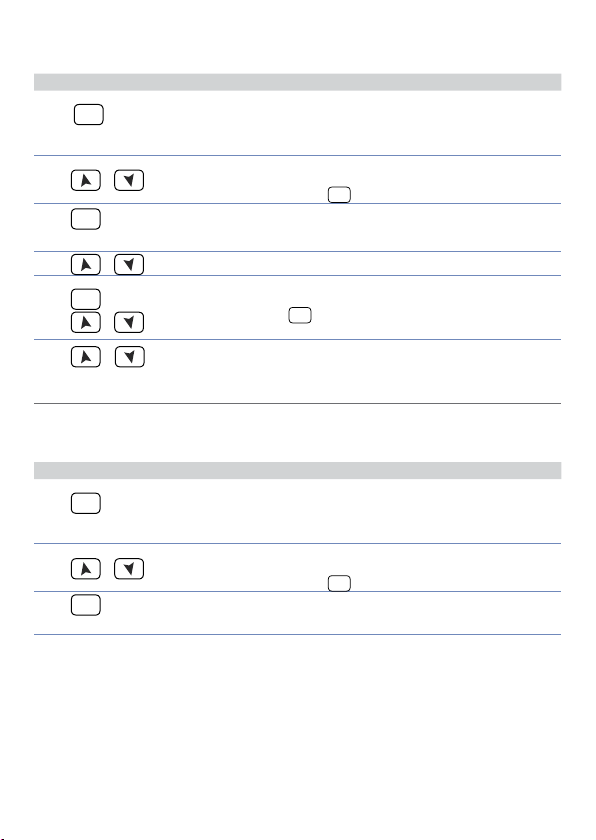
9 Accesso alla configurazione
Per parametri di configurazione vedi par. 10.
Premere Effetto Eseguire
SET
1
per 3 secondi
2
SET
3
per conferma
4
SET
5
6
contemporaneamente
Su display 1 compare
con la 1° cifra lampeggiante,
mentre sul display 2 compare
.
PASS
Si modifica la cifra
o
lampeggiante si passa alla
successiva con il tasto
Su display 1 compare il
primo parametro e sul
secondo il valore.
o
Scorre i parametri.
Si incrementa o decrementa
il valore visualizzato tenendo
o
+
premuto prima
tasto freccia.
Fine variazione parametri di
configurazione.
SET
Il regolatore esce dalla
programmazione.
0000
SET
e poi un
Inserire la password
.
Inserire il nuovo dato che
verrà salvato al rilascio dei
tasti. Per variare un altro
parametro tornare al punto 4.
1234
.
9.1 Caricamento valori di default
Questa procedura permette di ripristinare le impostazioni di fabbrica dello strumento.
1
2
3
Premere Effetto Eseguire
SET
per 3 secondi
o
SET
per conferma
Su display 1 compare
con la 1° cifra lampeggiante,
mentre sul display 2 compare
.
PASS
Si modifica la cifra
lampeggiante si passa alla
successiva con il tasto
Lo strumento carica le
impostazioni di fabbrica.
0000
Inserire la password
SET
.
Spegnere e riaccendere lo
strumento.
9999
.
Manuale d’uso CN243 - 71
Page 72

10 Tabella parametri di configurazione
L’elenco dei parametri sotto riportato è completo; alcuni di questi non appariranno sui
modelli che non dispongono delle relative risorse Hardware.
1
Command Output
C.out
selezione tipo uscita di comando (vedi tabelle sottostanti)
Default (necessario p er utilizzo funzione di ritrasmissione di processo e set
c. o1
con uscita Volt / mA)
Comando su uscita relè Q2
c. o2
Comando in tensione per SSR
c.SS r
Comando servo-valvole a loop aperto
c. uA L.
Comando con segnale 4...20 mA
c.4 . 2 0
Comando con segnale 0...20 mA
c.0.20
Comando con segnale 0...10 V
c.0.10
3
20
19
20
20
4
COMANDO ALLARME 1
CN243- R1F2
c. o1
c. o2
c.SS r
c. uA L.
c.4 . 2 0
c.0.20
c.0.10
Q1 Q2
Q2 Q1
SSR Q1
Q1 (apri) / Q2 (chiudi) -
4 ... 20 mA Q1
0 ... 20 mA Q1
0 ... 10 V Q1
CN243-R1R2F3
COMANDO ALLARME 1 ALLARME 2
c. o1
c. o2
c.SS r
c. uA L.
c.4 . 2 0
c.0.20
c.0.10
Q1 Q2 SSR
Q2 Q1 SSR
SSR Q1 Q2
Q1 (apri) / Q2 (chiudi) SSR -
4 ... 20 mA Q1 Q2
0 ... 20 mA Q1 Q2
0 ... 10 V Q1 Q2
CN243- R1R2R 3F4C4
COMANDO ALLARME 1 ALLARME 2 ALLARME 3
c. o1
c. o2
c.SS r
c. uA L.
c.4 . 2 0
c.0.20
c.0.10
3
Solo su CN243-R1F2 non impos tare se si utilizza la f unzione di ritrasmis sione del processo.
4
Non imposta re mai se si utilizza l a funzione di ritras missione del proces so.
72 - CN243 - Manuale d’uso
Q1 Q2 Q3 SSR
Q2 Q1 Q3 SSR
SSR Q1 Q2 Q3
Q2 (apri) / Q3 (chiudi) Q1 SSR -
4 ... 20 mA Q1 Q2 Q3
0 ... 20 mA Q1 Q2 Q3
0 ... 10 V Q1 Q2 Q3
Page 73

2
Sensor
SEN.
Configurazione ingresso analogico/selezione sensore
Tc- K (Default) -260 °C .. 1360 °C
Tc.K
Tc-S - 40 °C .. 1760 °C
Tc. s
Tc-R - 40 °C .. 1760 °C
Tc. r
Tc-J -200 °C .. 1200 °C
Tc. j
Pt100 -200 °C .. 600 °C
Pt
Pt100 -200 °C .. 140 °C
P t1
Ni100 -60 °C .. 180 °C
ni
NTC10K-β3435K -40 .. 125°C
n t c .1
NTC10K-OMEGA -40 .. 150°C
n tc.2
NTC2252-OMEGA -40 .. 150°C
n tc.3
PTC1K -50 °C .. 150 °C
Ptc
Pt500 -100 °C .. 600 °C
Pts
Pt1000 -100 °C .. 600 °C
P t1 k
0 .. 10 Volt
0 .1 0
0 .. 20 mA
0.20
4 .. 20 mA
4.20
0 .. 40 mVolt
0.4 0
Potenziometro max. 6 KOhm (Vedi paragrafo 7.9)
P o t .1
Potenziometro max. 150 KOhm (Vedi paragrafo 7.9)
Po t.2
T.A. con secondario 50 mA (s olo CN 243-R1R2 F3/R1R2 R3F4 C4)
t.A.
3
Decimal Point
d .P.
Seleziona il tipo di decimale visualizz ato
Default
0
1 Decimale
0.0
2 Decimali
0.00
3 Decimali
0.000
4
5
6
Lower Limit Setpoint
Lo . L. S.
Limite inferiore impostabile per il setpoint
-999…+9999 [digit
Upper Limit Setpoint
u p . L.S.
Limite superiore impostabile per il setpoint
-999…+9999 [digit
Default: 1750 .
Lower Linear Input
Lo L.i
Limite inferiore range AN1 solo per normalizzati. Es: con ingresso 4...20 mA questo
parametro assume il valore associato a 4 mA
-999 bis +9999 [digit
5
] (gradi.decimi per sensori di temperatura), Default: 0.
5
] (gradi.decimi per sensori di temperatura)
5
], Default: 0.
Manuale d’uso CN243 - 73
Page 74

7
8
Upper Linear Input
u p . L.i .
Limite superiore range AN1 solo per normalizzati. Es: con ingresso 4...20 mA questo
parametro assume il valore associato a 20 mA
-999 bis +9999 [digit
Latch On Function
La t c .
Impostazione automatica dei limiti per ingressi normalizzati e potenziometri (Ve di
5
], Default: 1000.
paragrafo 7.9)
Disabilitato (Default)
di s .
Standard
std .
Zero virtuale memorizzato
u.0 st.
Zero virtuale allo Start
u .0i n
Permette di superare i limiti inferiore e superiore se in ingresso ci sono
dYn .L
valori esterni al 0/4..20 mA o 0..10V.
9
10
11
12
13
74 - CN243 - Manuale d’uso
Offset Calibration
o . cAL.
Calibrazione offset. Valore che si somma o sottrae al processo visualizzato (es:
normalmente corregge il valore di temperatura ambiente).
-999…+1000 [digit
-200.0…+100.0 (gradi.decimi per sensori di temperatura),
Default 0.0.
Gain Calibration
G. cAL.
Calibrazione guadagno AI1. Valore che si moltiplica al processo per eseguire
calibrazione sul punto di lavoro.
-99.9%..+100.0%, Default: 0.0.
es: per correggere la scala di lavoro da 0...1000°C che visualizza 0...1010°C, fissare il
parametro a -1.0
Action type
Act. t.
Caldo (N.A.) (Default)
Heat
Freddo (N.C.)
coo L
Blocca comando sopra SPV. Es: uscita di comando disabilitata al raggiungi-
H.o.o.S.
Command Reset
c. re.
Tipo di riarmo del cont atto di comando (sempre automatico in f unzionamento P.I.D.)
Riarmo automatico (Default)
a re.
Reset manuale
m re.
Reset manuale memorizzato (mantiene lo stato del relè anche dopo un
m re.s .
Command State Error
c. S.e.
Stato del contatto per l’uscita di comando in caso di errore
Contatto aperto (Default)
c. o .
Contatto chiuso
c. c.
5
] per sensori normalizzati e potenziometri.
mento del setpoint anche con valore di P.I.D. diverso da zero.
eventuale mancanza di alimentazione)
Page 75

14
15
16
17
18
19
20
21
22
5
Dipende dall’impostazione del parametro
Command Led
c. Ld.
Definisce lo stato del led OUT1 in corrispondenza del relativo contatto
Acceso a contatto aperto
c. o .
Acceso a contatto chiuso (Default)
c. c.
Command Hysteresis
c. HY.
Isteresi in ON/OFF o banda morta in P.I.D.
-999…+999 [digit
Default
0.0.
Command Delay
c. de.
Ritardo co mando (solo in funzion amento ON / OFF). In caso di servo valvo la funziona
anche in P.I.D. e rappresenta il ritardo tra l’apertura e la chiusura dei due contat ti.
-180…+180 secondi (
Negativo: ritardo in fase di spegnimento.
Positivo: ritardo in fase di accensione. Default: 0.
Command Setpoint Protection
c. s. p.
Consente o meno di variare il valore del setpoint di comando
Modificabile dall’utente (Default)
free
Protetto
Lo c k
Proportional Band
p. b .
Banda prop orzionale. Inerzia del processo in unità (es: se temperatura in °C )
0 ON / OFF se
1-9999 [digit
Integral Time
t.i .
Tempo integrale. Inerzia del processo in secondi.
0.0-999.9 secondi (0 = integrale disabilitato), Default 0.0
Derivative Time
t.d.
Tempo derivativo. Normalmente ¼ del tempo integrale.
0.0-999.9 secondi (0 = derivativo disabilitato), Default 0.0
Cycle T ime
t. c.
Tempo di ciclo (per P.I.D. su teleruttore 10 / 15 sec, per P.I.D. su SSR 1 sec.) o tempo
servo-motore (valore dichiarato da produttore)
1-300 secondi (Default: 10)
Output Power Limit
o . P o L.
Seleziona il valore massimo per la percentuale dell’uscita di comando
0…10 0%, Default: 100 %.
Es: con
comando può variare da un minimo di 0 V al massimo di 9 V.
5
] (gradi.decimi per sensori di temperatura)
decimi di secondo
uguale a 0 (Default)
t.i .
5
] (gradi per sensori di temperatura)
selezionato 0...10 V e impostazione su
c.out
in caso di ser vo valvola).
e del parametro
sen.
d. p.
,
al 90%, l’uscita di
o . Po L.
Manuale d’uso CN243 - 75
Page 76

23
Alarm 1
A L .1
Selezione allarme 1. L’intervento dell’allarme è associato a AL1 (Vedi paragrafo 11)
Disabilitato (Default)
di s .
Assoluto / soglia, riferito al processo
A. AL.
Allarme di banda
b . AL.
Allarme di deviazione superiore
H. d. A L.
Allarme di deviazione inferiore
L. d .AL.
Assoluto / soglia, riferito al setpoint di comando
A. c.AL.
Allarme di stato (attivo in Run / Star t)
s t .A L.
Azione freddo (cooling) (Vedi paragrafo 7.12)
coo L
Allarme di stato “controllo carico” (Loop Break Alarm)
L. b .A.
Es: controlla lo stato dei contattori / SSR o delle resistenze
24
25
26
27
6
All’accension e, l’uscita è inibita se lo s trumento è in condizio ne di allarme. Si at tiva solo quando rien trato
dalla condizione d’allarme, questa si ripresenta.
76 - CN243 - Manuale d’uso
Alarm 1 State Output
A.I.5.0
Contatto uscita allarme 1 e tipo intervento.
(N.O. Start) Normalmente aperto, operativo dallo star t (Default)
n . o . s.
(N.C. Start) Normalmente chiuso, operativo dallo start
n . c. s.
(N.O. Threshold) Normalmente aperto, operativo al raggiungimento
n . o . t.
dell’allarme
(N.C. Threshold) Normalmente chiuso, operativo al raggiungimento
n . c. t.
dell’allarme
Alarm 1 Reset
a1 . r e .
Tipo di reset del contatto dell’allarme 1
Automatic Reset (Default)
a re.
Reset manuale (riarmo/reset manuale da tastiera)
m re.
Reset Manuale memorizzato (mantiene lo stato del relè anche dopo un
m re.s .
eventuale mancanza di alimentazione)
Alarm 1 State Reset
a .1 . s . e .
Stato del contatto per l’uscita di allarme 1 in caso di errore
Contatto aperto (Default)
c. o .
Contatto chiuso
c. c.
Alarm 1 Led
a.1.Ld.
Definisce lo stato del led OUT2 in corrispondenza del relativo contatto
Acceso a contatto aperto
c. o .
Acceso a contatto chiuso (Default)
c. c.
6
6
SET
Page 77

28
29
30
31
32
Alarm 1 Hysteresis
a .1 . H y .
Isteresi allarme 1
-999…+999 [digit
Alarm 1 Delay
a .1 . d e .
Ritardo allarme 1. -180…+180 secondi. Default: 0.
Negativo: ritardo in fase di uscita dall’allarme.
Positivo: ritardo in fase di entrata dell’allarme.
Alarm 1 Setpoint Protection
a .1 . s p .
Protezione set allarme 1. Non consente all’utente di variare il setpoint
Modificabile dall’utente (Default)
free
Protetto
Lo c k
Protetto e non visualizzato
Hi d e
Alarm 2
AL. 2
Selezione allarme 2. L’intervento dell’allarme è associato a AL2 (Vedi paragrafo 11)
Disabilitato (Default)
di s .
Assoluto / soglia, riferito al processo
A. AL.
Allarme di banda
b . AL.
Allarme di deviazione superiore
H. d. A L.
Allarme di deviazione inferiore
L. d .AL.
Assoluto / soglia, riferito al setpoint di comando
A. c.AL.
Allarme di stato (attivo in Run / Star t)
s t .A L.
Azione freddo (cooling)(Vedi paragrafo 7.12)
coo L
Allarme di stato “controllo carico” (Loop Break Alarm)
L. b .A.
Es: controlla lo stato dei contattori / SSR o delle resistenze
Alarm 2 State Output
a . 2. s o .
Contatto uscita allarme 2 e tipo intervento
(N.O. Start) Normalmente aperto, operativo dallo star t (Default)
n . o . s.
(N.C. Start) Normalmente chiuso, operativo dallo start
n . c. s.
(N.O. Threshold) Normalmente aperto, operativo al raggiungimento
n . o . t.
(N.C. Threshold) Normalmente chiuso, operativo al raggiungimento
n . c. t.
7
] (gradi.decimi per sensori di temperatura), Default: 0.0.
dell’allarme
dell’allarme
8
8
7
Dipende dall’impostazione del parametro
8
All’accension e, l’uscita è inibita se lo s trumento è in condizio ne di allarme. Si at tiva solo quando rien trato
dalla condizione d’allarme, questa si ripresenta.
e del parametro
sen.
d. p.
Manuale d’uso CN243 - 77
Page 78

33
34
35
36
37
38
39
Alarm 2 Reset
A2. re.
Tipo di riarmo del contatto dell’allarme 2.
Reset automatico (Default)
Are.
Reset manuale (riarmo/reset manuale da tastiera)
m re.
Reset manuale memorizzato (mantiene lo stato del relè anche dopo un
m re.s .
eventuale mancanza di alimentazione)
Alarm 2 State Error
a . 2. s . e .
Stato del contatto per l’uscita di allarme 2 in caso di errore.
Contatto aperto (Default)
c. o .
Contatto chiuso
c. c.
Alarm 2 Led
a.2.Ld.
Definisce lo stato del led OUT2 in corrispondenza del relativo contatto.
Acceso a contatto aperto
c. o .
Acceso a contatto chiuso (Default)
c. c.
Alarm 2 Hysteresis
a.2.HY.
-999…+999 [digit9] (gradi.decimi per sensori di temperatura), Default: 0.0.
Alarm 2 Delay
a.2.d.e.
-180…+180 secondi. Negativo: ritardo in fase di uscita dall’allarme.
Positivo: ritardo in fase di entrata dell’allarme. Default: 0.
Alarm 2 Setpoint Protection
a . 2. s . p .
Non consente all’operatore di variare il valore impostato.
Modificabile dall’utente (Default)
free
Protetto
Lo c k
Protetto e non visualizzato
Hi d e
Alarm 3
AL. 3
Selezione allarme 3. L’intervento dell’allarme è associato a AL3 (Vedi paragrafo 11)
Disabilitato (Default)
di s .
Assoluto / soglia, riferito al processo
A. AL.
Allarme di banda
b . AL.
Allarme di deviazione superiore
H. d. A L.
Allarme di deviazione inferiore
L. d .AL.
Assoluto / soglia, riferito al setpoint di comando
A. c.AL.
Allarme di stato (attivo in Run / Star t)
s t .A L.
Azione freddo (cooling) (vedi par. 7.12)
coo L
Allarme di stato “controllo carico” (Loop Break Alarm).
L. b .A.
Es: controlla lo stato dei contattori / SSR o delle resistenze
SET
9
Dipende dall’impostazione del parametro
78 - CN243 - Manuale d’uso
e del parametro
sen.
d. p.
Page 79

40
41
42
43
44
45
46
Alarm 3 State Output
a .3.5. o .
Contatto uscita allarme 3 e tipo intervento.
(N.O. Start) Normalmente aperto, operativo dallo star t (Default)
n . o . s.
(N.C. Start) Normalmente chiuso, operativo dallo start
n . c. s.
(N.O. Threshold) Normalmente aperto, operativo al raggiungimento
n . o . t.
dell’allarme
(N.C. Threshold) Normalmente chiuso, operativo al raggiungimento
n . c. t.
dell’allarme
Alarm 3 Reset
a .3. re .
Tipo di riarmo del contatto dell’allarme 3.
Reset automatico (Default)
a re.
Reset manuale (riarmo/reset manuale da tastiera)
m re.
Reset manuale memorizzato (mantiene lo stato del relè anche dopo un
m re.
eventuale mancanza di alimentazione)
Alarm 3 State Error
a .3.s . e.
Stato del contatto per l’uscita di allarme 3 in caso di errore.
Contatto aperto (Default)
c. o .
Contatto chiuso
c. c.
Alarm 3 LED
a.3.Ld.
Definisce lo stato del led OUT3 in corrispondenza del relativo contatto.
Acceso a contatto aperto
c. o .
Acceso a contatto chiuso (Default)
c. c.
Alarm 3 Hysteresis
a .3.HY.
Isteresi allarme 3
-999…+999 [digit
Alarm 3 Delay
a .3. d e.
Ritardo allarme 3. -180…+180 secondi. Default: 0.
Negativo: ritardo in fase di uscita dall’allarme.
Positivo: ritardo in fase di entrata dell’allarme.
Alarm 3 Setpoint Protection
a .3.s . p.
Protezione set allarme 3. Non consente all’operatore di variare il valore impostato.
Modificabile dall’utente (Default)
free
Protetto
Lo c k
Protetto e non visualizzato
Hi d e
10
10
11
] (gradi.decimi per sensori di temperatura), Default: 0.0.
10
All’accension e, l’uscita è inibita se lo s trumento è in condizio ne di allarme. Si at tiva solo quando rien trato
dalla condizione d’allarme, questa si ripresenta.
11
Dipende dall’impostazione del parametro
e del parametro
sen.
d. p.
Manuale d’uso CN243 - 79
Page 80

47
Amperometric Transformer
t.a.
Abilitazione e range di fondo-scala del trasformatore amperometrico.
0 Disabilitato.
1-20 0 Ampere
Default: 0
48
49
50
51
52
53
Loop Break Alarm Threshold
L.b.a.t.
Soglia di intervento del Loop Break Alarm.
0.0-200.0 Ampere. Default: 50.0
Loop Break Alarm Delay
L.b.a.d.
Tempo di ritardo p er l’intervento del Loop Break Alarm.
00.00- 60.00 mm.ss
(Default: 01.0 0)
Cooling Fluid
co o .f.
Tipo di fluido refrigerante in modalità P.I.D. caldo / freddo
Aria (Default)
Ai r
Olio
oi L
Acqua
H2o
Proportional Band Multiplier
p.b.m.
Moltiplicatore di banda proporzionale. La banda proporzionale per l’azione freddo è
data dal valore del parametro 18 moltiplicato per questo valore.
1.00-5.00 (Default: 1.0 0)
Overlap / Dead Band
oud.b.
Sovrapposizione / Banda Morta. In modalità P.I.D. caldo / freddo (doppia azione)
definisce la combinazione di banda morta per l’azione di riscaldamento e raffreddamento.
-20.0-50.0% del valore di banda proporzionale (Default: 0).
Negativo indica il valore di banda morta, positivo significa la sovrapposizione.
Cooling Cycle Time
co.t.c.
Tempo ciclo per uscita refrigerante.
1-300 secondi, Default: 10.
80 - CN243 - Manuale d’uso
Page 81

54
55
Conversion Filter
c. fLt.
Filtro ADC: numero di letture del sensore di ingresso per il calcolo della media che
definisce il valore del processo. NB: con l’aumento delle medie rallenta la velocità
del loop di controllo.
Disabilitato
di s .
Media con 2 campionamenti
2. s. m .
Media con 3 campionamenti
3. s. m .
Media con 4 campionamenti
4. s. m .
Media con 5 campionamenti
5. s. m .
Media con 6 campionamenti
6. s. m .
Media con 7 campionamenti
7. s. m .
Media con 8 campionamenti
8. s. m .
Media con 9 campionamenti
9. s. m .
Media con 10 campionamenti (Default)
10.s . m .
Media con 11 campionamenti
11 . s . m .
Media con 12 campionamenti
12. s . m .
Media con 13 campionamenti
13.s .m .
Media con 14 campionamenti
14.s . m.
Media con 15 campionamenti
15.s . m.
Conversion Frequency
c. frn .
Frequenza di campionamento del convertitore analogico-digitale.
NB: Aumentando la velocità di conversione diminuisce la stabilità di lettura (es:
per transitori veloci come la pressione consigliabile aumentare la frequenza di
campionamento).
242 Hz (Massima velocità di conversione)
242H.
123 Hz
123H.
62 Hz
62 H.
50 Hz
50 H.
39 Hz
39 H.
33.2 Hz
33.2 H.
19.6 Hz
19.6H.
16.7 Hz (Default) Ideale per filtraggio disturbi 50 / 60 Hz
1 6 .7H .
12 .5 H z
12.5 H.
10 Hz
10 H.
8.33 Hz
8.33H.
6.25 Hz
6.25H .
4.17 Hz (Minima velocità di conversione)
4 .1 7 H.
Manuale d’uso CN243 - 81
Page 82

56
57
58
59
Visualization Filter
u . FLt .
Filtro in visualizzazione. Rallenta l’aggiornamento del valore di processo visualizzato
sul display per facilitarne la lettura.
Disabilitato e filtro a “forchetta” (massima velocità di aggiornamento
di s .
display) (Default)
Filtro del primo ordine con filtro a “forchetta”
fi . o r.
Media con 2 campionamenti
2. s. m .
Media con 3 campionamenti
3. s. m .
Media con 4 campionamenti
4. s. m .
Media con 5 campionamenti
5. s. m .
Media con 6 campionamenti
6. s. m .
Media con 7 campionamenti
7. s. m .
Media con 8 campionamenti
8. s. m .
Media con 9 campionamenti
9. s. m .
Media con 10 campionamenti (massimo rallentamento di aggiornamento
10.s . m .
display)
Disabilitato senza filtro a “forchetta”
n u LL
Filtro del primo ordine
f. o . 2
Tun e
tun e
Selezione tipo autotuning (Vedi paragrafo 7.2)
Disabilitato (Default)
diS .
Automatico (Calcolo parametri P.I.D. all’accensione e al variare del set)
Auto
Manuale (Lanciato dai tasti o da ingresso digitale)
Man.
Sincronizzato [Vedere word modbus 1025 (solo CN243-R1R2F3)]
sYn c.
Setpoint Deviation Tune
s.d.tu.
Imposta la deviazione dal setpoint di comando come soglia usata dall’ autotuning,
per il calcolo dei parametri P.I.D.
0-5000 [digit
op.mo.
Selezione funzionamento (Vedi paragrafo 11)
co nt.
p r. cY.
2t.s .
2t . s .i.
3 t. s .i.
4 t. s .i.
t. res .
p.c.s.s.
S.S. cY
12
] (decimi di grado se temperatura), Default: 10 .
Operating Mode
Regolatore (Default)
Ciclo pre-programmato (Vedi paragrafo 7.7)
Cambio set da ingresso digitale
Cambio set da ingresso digitale con comando ad impulso
Cambio di 3 set da ingresso digitale con comando ad impulso
Cambio di 4 set da ingresso digitale con comando ad impulso
Time reset (funzione personalizzata)
Ciclo pre-programmato con Start / Stop solo da ingresso digitale
Come
, ma con alcune varianti)
p r. cY.
12
Dipende dall’impostazione del parametro
82 - CN243 - Manuale d’uso
e del parametro
sen.
d. p.
Page 83

60
61
Automatic / Manual
au.ma.
Abilita la selezione automatico/manuale (Vedi paragrafo 7.6)
Disabilitato (Default)
di s .
Abilitato
En.
Abilitato con memoria
En .St.
Digital Input
d G t .i .
Funzionamento ingresso digitale (sel P59 deve essere
Disabilitato (Default)
di s .
Ciclo pre-programmato con Start / Stop
st.s t.
Run N.O. (abilita regolazione con contatto normalmente aperto)
rn.n.o.
Run N.C. (abilita regolazione con contatto normalmente chiuso)
rn.n.c.
Lock conversion N.O. (funzione mantenimento visualizzazione)
L.c.n.o.
Lock conversion N.C.
L.c.n.c.
Tune (abilita l’auto-tuning manualmente)
tu n e
Automatic / manual impulsive (se abilitato su parametro 60)
a.ma.i.
Automatic / manual contac t (se abilitato su parametro 60)
a.ma.c.
co nt.
o
) (Vedi paragrafo 11)
Pr. cY .
62
63
64
65
13
Gradient
Gra d .
Gradiente di salita per Soft-Start o ciclo pre-programmato.
0 Disabilitato
1-9999 [Digit/hour
temperatura), Default: 0.
Maintenance Time
m a . ti .
Tempo mantenimento per ciclo pre-programmato
00.00-24.00 hh.mm. Default: 00.00
User Menu Cycle Programmed
u.m.c.p.
Permette di modificare gradiente di salita e tempo di mantenimento dal menù
utente, in funzionamento ciclo pre -programmato
Disabilitato (Default)
di s .
Solo gradiente
Gra d .
Solo tempo di mantenimento
m a . ti .
Sia gradiente che tempo di mantenimento
ALL
Visualization Type
ui . tY.
Definisce la visualizzazione per il display 1 e 2.
1 Processo, 2 Setpoint (Default)
1. p.2. s .
1 Processo, 2 si spegne dopo 3 sec.
1. p.2.H.
1 Setpoint, 2 Processo
1.s.2.P.
1 Setpoint, 2 si spegne dopo 3 sec.
1.s .2.H.
1 Processo, 2 Ampere (da ingresso T.A.)
1.p.2.a.
Dipende dall’impostazione del parametro
13
] (gradi/ora con visualizzazione in decimi per sensori di
SET
e del parametro
sen.
d. p.
Manuale d’uso CN243 - 83
Page 84

66
Degree
d eG r.
Selezione tipo gradi
Gradi Centigradi (Default)
c
Gradi Fahrenheit
f
67
68
69
70
71
14
La visualizzazione del punto decimale dipende dall’impostazione del parametro
d. p.
84 - CN243 - Manuale d’uso
Retransmission
re tr.
Ritrasmissione per uscita 0-10 V o 4..20 mA (Selezionare Jumper JP5, JP7 e JP9).
Parametri 68 e 69 definiscono il limite inf. e sup. della scala di funzionamento.
Disabilitato
di s .
Ritrasmette il processo in Volt
u o . p.
Ritrasmette il processo in mA
m a . p.
Ritrasmette il setpoint di comando in Volt
u o . c.
Ritrasmette il setpoint di comando in mA
m a . c.
Volt uscita percentuale comando
uo.o.p.
mA uscita percentuale comando
ma.o.p.
Volt setpoint di allarme 1
uo.a.1
mA setpoint di allarme 1
ma.a.1
Volt setpoint di allarme 2
uo.a.2
mA setpoint di allarme 2
ma.a.2
Vo lt T.A .
uo.t.a.
mA T. A.
ma.t.a.
Lower Limit Retransmission
Lo .L. r.
Limite inferiore range ritrasmissione uscita Volt/mA
-999…+9999 [digit
Upper Limit Retransmission
up.L.r.
Limite superiore range ritrasmissione uscita Volt/mA.
-999…+9999 [digit14] (gradi.decimi per sensori di temperatura), Default: 1000.
Baud Rate
bd . rt.
Seleziona il baud rate per la comunicazione seriale
4.800 Bit/s
4.8 k
9.600 Bit/s
9.6 k
19.200 Bit/s (Default)
19.2k
28.800 Bit/s
28.8 k
39.400 Bit/s
39 .4 k
57.600 Bit/s
57.6 k
Slave Address
sL. a d .
Seleziona l’indirizzo dello slave per la comunicazione seriale.
1 – 254. Default: 254
14
] (gradi.decimi per sensori di temperatura), Default: 0.
sen.
e del parametro
Page 85
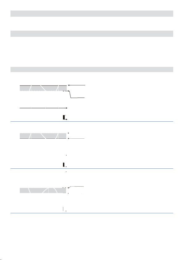
72
Time
Serial Delay
se. d e.
Seleziona il ritardo seriale
0 – 100 millisecondi. Default: 20
73
Lower Limit Output Percentage
L.L. o . p.
Seleziona il valore minimo per la percentuale dell’uscita di comando.
0 – 100%, Default: 0%.
Es: con
può variare da un minimo di 1 V al massimo di 10 V.
selezionato 0...10 V e impostazione su
c.out
L.L. o .P.
11 Modi d’intervento allarme
11. a Allarme assoluto o allarme di soglia (selezione
Pv
1
On On
O
O
2
On On
O
O
3
On On
O
O
Alarm Spv
Hysteresis
Allarme assoluto con regolatore in
parameter
funzionamento caldo (par. 11
> 0
selezionato
di “0” (par. 28
Time
Alarm
output
Hysteresis
parameter
< 0
Alarm Spv
Allarme assoluto con regolatore in
Heat
A.1. HY.
funzionamento caldo (par. 11
selezionando
di “0” (par. 28
Time
Alarm
output
Hysteresis
parameter
Allarme assoluto con regolatore in
> 0
funzionamento freddo (par. 11
Alarm Spv
selezionando
maggiore di “0” (par. 28
Alarm
output
Heat
A.1. HY.
Heat
al 10%, l’uscita di comando
)
a . AL.
) e valore di isteresi maggiore
Act. t.
> 0). *
) e valore di isteresi minore
Act. t.
< 0). *
) e valore di isteresi
> 0). *
A.1. HY.
Act. t.
Manuale d’uso CN243 - 85
Page 86
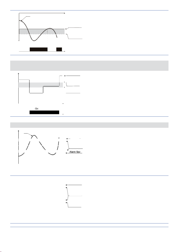
Time
Pv
parameter
output
output
Comand Spv
Alarm Spv
Hysteresis
Alarm Spv
Alarm Spv
Allarme assoluto con regolatore in
funzionamento freddo (par. 11
4
O O
On On
Hysteresis
< 0
Alarm
selezionato
“0” (par. 28
) e valore di isteresi minore di
coo L
< 0). *
A.1. HY.
11. b Allarme assoluto o allarme di soglia riferito al setpoint di comando
(selezione
1
O O
a . c. AL.
)
Hysteresis
Allarme assoluto riferito al set di comando,
parameter
> 0
con regolatore in funzionamento caldo (par. 11
selezionando
Act. t.
Alarm Spv
maggiore di “0” (par. 28
Il set di comando può essere variato con la
Time
pressione dei tasti freccia da frontale o con
comandi su porta seriale RS485. *
Alarm
Heat
A.1. HY.
) e valore di isteresi
> 0).
Act. t.
11. c Allarme di Banda (selezione
Pv
1
On On On
O O
Pv
Comand Spv
2
On On On
O O
* L’esempio è rif erito all’allarme 1; la funzio ne è abilitab ile anche p er gli allar mi 2 e 3 sui modelli che li
prevedono.
86 - CN243 - Manuale d’uso
Alarm Spv
Hysteresis
parameter
> 0
Time
Alarm
output
parameter
< 0
Alarm Spv
Hysteresis
parameter
< 0
Time
Alarm
output
)
b . AL.
Allarme di banda valore di isteresi maggiore di
“0” (par. 28
A.1. HY.
> 0). *
Allarme di b anda valore di istere si minore di “0”
A.1. HY.
< 0). *
(par. 28
Page 87
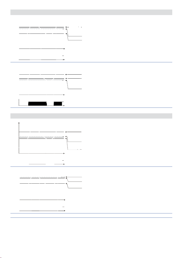
11. d Allarme deviazione superiore (selezione
output
Alarm Spv
Comand Spv
output
Comand Spv
Alarm Spv
Alarm Spv
Alarm Spv
Alarm Spv
Comand Spv
Comand Spv
Comand Spv
Comand Spv
Alarm Spv
Alarm Spv
Pv
Alarm Spv
Hysteresis
parameter
Allarme di deviazione superiore e valore di
> 0
1
O O
Pv
2
O O
On On
On On
Comand Spv
Time
Alarm
Comand Spv
Alarm Spv
Hysteresis
parameter
> 0
Time
Alarm
setpoint allarme maggiore di “0” e valore di
isteresi maggiore di “0” (par. 28
Allarme di deviazione superiore valore di
setpoint allarme minore di “0” e valore di
isteresi maggiore di “0” (par. 28
H. d . AL.
)
> 0). **
A.1. HY.
> 0). **
A.1. HY.
11. e Allarme deviazione inferiore (selezione
Pv
Comand Spv
Hysteresis
parameter
Allarme di deviazione inferiore valore di
1
On On
O O
Pv
2
On On
O O
** a) L’esempio è rif erito all’allarme 1; la funzio ne è abilitab ile anche per gli allar mi 2 e 3 sui model li che li
prevedono . b) Con isteresi minore di “0” (
allarme.
> 0
setpoint allarme maggiore di “0” e valore di
Alarm Spv
isteresi maggiore di “0” (par. 28
Time
Alarm
output
Hysteresis
parameter
> 0
Alarm Spv
Allarme di deviazione inferiore valore di
Comand Spv
setpoint allarme minore di “0” e valore di
isteresi maggiore di “0” (par. 28
Time
Alarm
output
< 0) la linea trat teggiata si sp osta sopra il se tpoint di
A.1. HY.
L. d .A L.
)
A.1. HY.
A.1. HY.
Manuale d’uso CN243 - 87
> 0). **
> 0). **
Page 88

12 Tabella segnalazioni anomalie
In caso di mal funzionamento dell’impianto il controllore spegne l’uscita di regolazione
e segnala il tipo di anomalia riscontrata. Per esempio il regolatore segnalerà la rottura
di un’eventuale termocoppia collegata visualizzando
una breve descrizione
Per le altre segnalazioni vedere la tabella sottostante.
E-01
SYS.E
E-02
SYS.E
E-04
SYS.E
E-05
prb .
E-08
SYS.E
(sonda) sul display 2.
prb .
Errore in programmazione cella
EEPROM.
Guasto sensore temperatura
giunto freddo o temperatura
ambiente al di fuori dei limiti
ammessi.
Dati di configurazione errati.
Possibile perdita della tarature
dello strumento.
Termocoppia aperta o
temperatura fuori limite.
Tarature mancanti. Contattare Assistenza.
Causa Cosa fare
(lampeggiante) sul display 1 e
e -05
Contattare Assistenza.
Contattare Assistenza.
Verificare che i parametri di
configurazione siano corretti.
Controllare il collegamento con
le sonde e la loro integrità.
Note / Aggiornamenti
88 - CN243 - Manuale d’uso
Page 89

Tabella delle configurazioni dei parametri
1
2
3
4
5
6
7
8
9
10
11
12
13
14
15
16
17
18
19
20
21
22
23
24
25
26
27
28
29
30
31
32
33
34
35
36
37
38
39
40
41
42
43
Command Output 74
C.out
Sensor 75
SEN.
Decimal Point 75
d .P.
Lower Limit Setpoint 75
Lo . L. S.
Upp er Limit Setpoint 75
u p . L.S.
Lower Linear Input 75
Lo L.i
Upper Linear Input 75
u p . L.i .
Latch On Function 76
La t c .
Offset Calibration 76
o . cAL.
Gain Calibration 76
G . cAL.
Action type 76
Act. t.
Command Reset 76
c. re.
Command State Error 76
c. S.e.
c. Ld.
c. s. p.
a .1 . d e .
Command Led 76
Command Hysteresis 77
c. HY.
Command Delay 77
c. de.
Command Setpoint Protection 77
Proportional Band 77
p. b .
Integral T ime 77
t.i .
Derivative Time 77
t.d.
Cycle Time 77
t. c.
Output Power Limit 77
o . P o L.
Alarm 1 78
A L .1
Alarm 1 State Output 78
A.I.5.0
Alarm 1 Reset 78
a1 . r e .
Alarm 1 State Reset 78
a .1 . s . e .
Alarm 1 Led 78
a.1.Ld.
Alarm 1 Hysteresis 79
a .1 . H y .
Alarm 1 Delay 79
Alarm 1 Setpoint Protection 79
a .1 . s p .
Alarm 2 79
AL. 2
Alarm 2 State Output 79
a . 2. s o .
Alarm 2 Reset 80
A2. re.
Alarm 2 State Error 80
a . 2. s . e .
Alarm 2 Led 80
a.2.Ld.
Alarm 2 Hysteresis 80
a.2.HY.
Alarm 2 Delay 80
a.2.d.e.
Alarm 2 Setpoint Protection 80
a . 2. s . p .
Alarm 3 80
AL. 3
Alarm 3 State Output 81
a .3.5. o .
Alarm 3 Reset 81
a .3. re .
Alarm 3 State Error 81
a .3.s . e.
Alarm 3 LED 81
a.3.Ld.
Manuale d’uso CN243 - 89
Page 90

44
45
46
47
48
49
50
51
52
53
54
55
56
57
58
59
60
61
62
63
64
65
66
67
68
69
70
71
72
73
Alarm 3 Hysteresis 81
a .3.HY.
Alarm 3 Delay 81
a .3. d e.
Alarm 3 Setpoint Protection 81
a .3.s . p.
Amperometric Transformer 82
t.a.
Loop Break Alarm Threshold 82
L.b.a.t.
Loop Break Alarm Delay 82
L.b.a.d.
Cooling Fluid 82
co o .f.
Proportional Band Multiplier 82
p.b.m.
Overlap / Dead Band 82
oud.b.
Cooling Cycle Time 82
co.t.c.
Conversion Filter 83
c. fLt.
Conversion Frequency 83
c. frn .
Visualization Filter 84
u . FLt .
Tune 84
tun e
Setpoint Deviation Tune 84
s.d.tu.
Operating Mode 84
op.mo.
Automatic / Manual 85
au.ma.
Digital Input 85
d G t .i .
Gradient 85
Gra d .
Maintenance Time 85
m a . ti .
User Menu Cycle Programmed 85
u.m.c.p.
Visualization Type 85
ui . tY.
Degree 86
d eG r.
r e t r.
Retransmission 86
Lower Limit Retransmission 86
Lo .L. r.
Upper Limit Retransmission 86
up.L.r.
Baud Rate 86
bd . rt.
Slave Address 86
sL. a d .
Serial Delay 87
se. d e.
Lower Limit Output Percentage 87
L.L. o . p.
90 - CN243 - Manuale d’uso
Page 91

OMEGA ENGINEERING, INC. warrants this unit to be free of defects in materials and workmanship
for a period of 13 months from date of purchase. OMEGA’s Warranty adds an additional one (1)
month grace period to the normal one (1) year product warranty to cover handling and shipping
time. This ensures that OMEGA’s customers receive maximum coverage on each product.
If the unit malfunctions, it must be returned to the factory for evaluation. OMEGA’s Customer
Service Department will issue an Authorized Return (AR) number immediately upon phone or
written request. Upon examination by OMEGA, if the unit is found to be defective, it will be repaired
or replaced at no charge. OMEGA’s WARRANTY does not apply to defects resulting from any action
of the purchaser, including but not limited to mishandling, improper interfacing, operation outside
of design limits, improper repair, or unauthorized modification. This WARRANTY is VOID if the
unit shows evidence of having been tampered with or shows evidence of having been damaged
as a result of excessive corrosion; or current, heat, moisture or vibration; improper specification;
misapplication; misuse or other operating conditions outside of OMEGA’s control. Components in
which wear is not warranted, include but are not limited to contact points, fuses, and triacs.
OMEGA is pleased to offer suggestions on the use of its various products. However,
OMEGA neither assumes responsibility for any omissions or errors nor assumes
liability for any damages that result from the use of its products in accordance with
information provided by OMEGA, either verbal or written. OMEGA warrants only that
the parts manufactured by the company will be as specified and free of defects. OMEGA
MAKES NO OTHER WARRANTIES OR REPRESENTATIONS OF ANY KIND WHATSOEVER,
EXPRESSED OR IMPLIED, EXCEPT THAT OF TITLE, AND ALL IMPLIED WARRANTIES
INCLUDING ANY WARRANTY OF MERCHANTABILITY AND FITNESS FOR A PARTICULAR
PURPOSE ARE HEREBY DISCLAIMED. LIMITATION OF LIABILITY: The remedies of
purchaser set forth herein are exclusive, and the total liability of OMEGA with respect
to this order, whether based on contract, warranty, negligence, indemnification, strict
liability or otherwise, shall not exceed the purchase price of the component upon which
liability is based. In no event shall OMEGA be liable for consequential, incidental or
special damages.
CONDITIONS: Equipment sold by OMEGA is not intended to be used, nor shall it be used: (1) as
a “Basic Component” under 10 CFR 21 (NRC), used in or with any nuclear installation or activity;
or (2) in medical applications or used on humans. Should any Product(s) be used in or with any
nuclear installation or activity, medical application, used on humans, or misused in any way,
OMEGA assumes no responsibility as set forth in our basic WARRANTY/ DISCLAIMER language,
and, additionally, purchaser will indemnify OMEGA and hold OMEGA harmless from any liability or
damage whatsoever arising out of the use of the Product(s) in such a manner.
WARRANTY/ DISCLAIMER
Direct all warranty and repair requests/inquiries to the OMEGA Customer Service Department.
BEFORE RETURNING ANY PRODUCT(S) TO OMEGA, PURCHASER MUST OBTAIN AN AUTHORIZED
RETURN (AR) NUMBER FROM OMEGA’S CUSTOMER SERVICE DEPARTMENT (IN ORDER TO
AVOID PROCESSING DELAYS). The assigned AR number should then be marked on the outside of
the return package and on any correspondence. The purchaser is responsible for shipping charges,
freight, insurance and proper packaging to prevent breakage in transit.
FOR WARRANTY RETURNS, please have
the following information available BEFORE
contacting OMEGA:
1. Purchase Order number under which the
product was PURCHASED,
2. Model and serial number of the product
under warranty, and
3. Repair instructions and/or specific
problems relative to the product.
OMEGA’s policy is to make running changes, not model changes, whenever an improvement
is possible. This affords our customers the latest in technology and engineering. OMEGA is a
registered trademark of OMEGA ENGINEERING, INC.
© Copyright 2015 OMEGA ENGINEERING, INC. All rights reserved. This document may not be
copied, photocopied, reproduced, translated, or reduced to any electronic medium or machinereadable form, in whole or in part, without the prior written consent of OMEGA ENGINEERING, INC.
RETURN REQUESTS/ INQUIRIES
FOR NON-WARRANTY REPAIRS,
for current repair charges. Have the following
information available BEFORE contacting
OMEGA:
1. Purchase Order number to cover the COST
of the repair,
2. Model and serial number of the product, and
3. Repair instructions and/or specific problems
relative to the product.
consult OMEGA
Page 92

Where Do I Find Everything I Need for
Process Measurement and Control?
OMEGA…Of Course!
Shop online at omega.com
TEMPERATURE
MU
Thermocouple, RTD & Thermistor Probes, Connectors,
Panels & Assy.
MU
Wire: Thermocouple, RTD & Thermistor
MU
Calibrators & Ice Point References
MU
Recorders, Controllers & Process Monitors
MU
Infrared Pyrometers
PRESSURE, STRAIN AND FORCE
MU
Transducers & Strain Gages
MU
Load Cells & Pressure Gages
MU
Displacement Transducers
MU
Instrumentation & Accessories
FLOW/LEVEL
MU
Rotameters, Gas Mass Flowmeters & Flow Computers
MU
Air Velocity Indicators
MU
Turbine/Paddlewheel Systems
MU
Totalizers & Batch Controllers
pH/CONDUCTIVITY
pH Electrodes, Testers & Accessories
MU
Benchtop/Laboratory Meters
MU
Controllers, Calibrators, Simulators & Pumps
MU
Industrial pH & Conductivity Equipment
DATA ACQUISITION
MU
Data Acquisition & Engineering Software
MU
Communications-Based Acquisition Systems
MU
Plug-in Cards for Apple, IBM & Compatibles
MU
Data Logging Systems
MU
Recorders, Printers & Plotters
HEATERS
MU
Heating Cable
MU
Cartridge & Strip Heaters
MU
Immersion & Band Heaters
MU
Flexible Heaters
MU
Laboratory Heaters
ENVIRONMENTAL MONITORING AND CONTROL
MU
Metering & Control Instrumentation
MU
Refractometers
MU
Pumps & Tubing
MU
Air, Soil & Water Monitors
MU
Industrial Water & Wastewater Treatment
MU
pH, Conductivity & Dissolved Oxygen Instruments
sm
M5303/1015
 Loading...