

Page 1

®
®
User’s Guide
Shop online at
omega.com
®
e-mail: [email protected]
For latest product manuals:
www.omegamanual.info
MADE IN UNITED KINGDOM
CN2300 SERIES
GRAPHICAL CONTROLLER
With Profiling &
Optional Recording
Page 2

omega.com [email protected]
Servicing North America:
U.S.A.: Omega Engineering, Inc., One Omega Drive, P.O. Box 4047
Stamford, CT 06907-0047 USA
Toll-Free: 1-800-826-6342 (USA & Canada only)
Customer Service: 1-800-622-2378 (USA & Canada only)
Engineering Service: 1-800-872-9436 (USA & Canada only)
Tel: (203) 359-1660 Fax: (203) 359-7700
e-mail: [email protected]
Canada: Toll-Free: 1-800-826-6342 (USA & Canada only)
Servicing Mexico:
Mexico: Tel: 001-800-099-0420 (Mexico Only) Tel: 001-203-357-7577 (Outside Mexico)
Fax: 001-203-968-7290 e-mail: [email protected]
Web: mx.omega.com
Servicing Latin America:
Latin America: Tel: 001 (203) 359-1660 Fax: 001 (203) 359-7700
e-mail: [email protected]
Servicing Asia:
China: Hotline: (+86) 800 819 0559, (+86) 400 619 0559
Servicing Europe:
France: Freephone: 0805 541 038 (France only)
Germany/Austria: Freephone: 0800 826 6342 (Germany only)
Italy: Freephone: 800 906 907 (Italy Only)
Netherlands: Freephone: 0800 099 33 44 (Netherlands only)
Benelux Tel: +31 070 770 3815 Fax: +31 070 770 3816
Spain: Freephone: 800 900 532 (Spain only)
United Kingdom: Freephone: 0800 488 488 (United Kingdom only)
The information contained in this document is believed to be correct, but OMEGA accepts no liability for any errors it contains, and reserves
the right to alter specifications without notice.
WARNING: These products are not designed for use in, and should not be used for, human applications.
Page 3

CN2300 Series Graphical Controller
with Profiling & Optional Recording
Page iv March 2012
Page 4

THIS MANUAL SUPPLEMENTS THE CONCISE PRODUCT MANUAL(S) SUPPLIED WITH
EACH INSTRUMENT AT THE TIME OF SHIPMENT. INFORMATION IN THIS
INSTALLATION, WIRING AND OPERATION MANUAL IS SUBJECT TO CHANGE
WITHOUT NOTICE.
Copies of this manual are available in electronic format at www.omega.com
Note:
It is strongly recommended that applications incorporate a high or low limit protective
device, which will shut down the equipment at a preset process condition in order to
prevent possible damage to property or products.
WARNING:
THE INTERNATIONAL HAZARD SYMBOL IS INSCRIBED ADJACENT TO THE REAR
CONNECTION TERMINALS. IT IS IMPORTANT TO READ THIS MANUAL BEFORE
INSTALLING OR COMMISSIONING THE UNIT.
WARNING:
THIS SYMBOL MEANS THE EQUIPMENT IS PROTECTED THROUGHOUT BY DOUBLE
INSULATION.
Products covered by this manual are suitable for Indoor use, Installation Category II,
Pollution category 2 environments.
This user guide covers all versions of the Omega CN2300 Series controller.
March 2012 Page v
Page 5

How to use this manual
This manual is structured to give easy access to the information required for all aspects of
the installation and use and of the Graphical Controller. The main sections are shown here,
followed by a full table of contents.
Section 1: Introduction - A brief description of the product and it’s features.
Section 2: Installation - Unpacking, installing and panel mounting instructions.
Section 3: Field Upgrade Options - Installation of the plug-in option modules.
Section 4: Wiring Instructions - Guidance on good wiring practice, noise avoidance,
wiring diagrams and input/output connections.
Section 5: Powering Up - Powering up procedure and descriptions of displays & switches.
Section 6: Messages & Error Indications - Display Messages and fault indications.
Section 7: Configuration & Use - Describes operating and configuration modes available.
These include Operation Mode; the Main and Configuration menus; the Easy Setup Wizard;
Supervisor Mode; Automatic tuning; Product and Service Information. Also available on
some models are menus to setup the USB, Data Recorder and Profiler features.
Section 8: The USB Interface Option – Describes uploading or downloading of
instrument settings, profiles or recorder logs to a USB memory stick.
Section 9: The Data Recorder Option – Describes the Data recorder feature. This allows
process data to be stored in to memory for later download and analysis.
Section 10: The Profiler Option – Describes the Profiler feature. A profile controls the
value of the setpoint over time; increasing, decreasing or holding its value as required.
Section 11: Manually Tuning Controllers - Advice on manually adjusting the controller to
the process characteristics.
Sections 12: Serial Communications - Details the physical layer and message formats
used for the RS485 and Ethernet communications options.
Sections 13: Modbus Parameters - Details the parameter addresses and data formats used
for the Modbus RTU and TCP communications protocols.
Section 14: Calibration - Step-by-step instructions to calibrate the instrument. This section
is intended for use by suitably qualified personnel.
Appendix 1: Glossary - Explanations of the terms used and product features.
Appendix 2: PC Software – Using the software suite.
Appendix 3: Specifications - Technical specifications for all products in the range.
Page 6 March 2012
Page 6

Contents Page Number:
1 Introduction........................................................................................................................... 15
2 Installation ............................................................................................................................ 16
Unpacking ................................................................................................................................................. 16
Installation ................................................................................................................................................. 16
Panel-Mounting ......................................................................................................................................... 16
Cleaning .................................................................................................................................................... 17
3 Field Upgrade Options ......................................................................................................... 18
Options Modules and Functions ............................................................................................................... 18
Preparing to Install or Remove Options Modules ..................................................................................... 19
Removing/Replacing Option Modules ...................................................................................................... 20
Replacing the Instrument in its Housing ................................................................................................... 21
Auto Detection of Option Modules ............................................................................................................ 21
Replacement of Power Supply or Input Boards ........................................................................................ 21
Data Recorder Board ................................................................................................................................ 22
Profiler Enabling ........................................................................................................................................ 22
4 Electrical Installation ............................................................................................................ 23
Installation Considerations ........................................................................................................................ 23
AC Power Wiring - Neutral (for 100 to 240V AC versions) ....................................................................... 23
Wire Isolation ............................................................................................................................................ 23
Use of Shielded Cable .............................................................................................................................. 24
Noise Suppression at Source ................................................................................................................... 24
Sensor Placement (Thermocouple or RTD) ............................................................................................. 25
Thermocouple Wire Identification Chart ................................................................................................... 25
Connections and Wiring ............................................................................................................................ 26
Power Connections ............................................................................................................................. 27
Universal Input Connections ............................................................................................................... 28
Option Slot 1 Connections ................................................................................................................... 30
Option Slot 2 Connections ................................................................................................................... 31
Option Slot 3 Connections ................................................................................................................... 33
Option Slot 4 Connections ................................................................................................................... 36
Option Slot A Connections .................................................................................................................. 37
Option Slot B Connections .................................................................................................................. 38
5 Powering Up .......................................................................................................................... 39
Powering Up Procedure ............................................................................................................................ 39
Front Panel Overview ............................................................................................................................... 39
Display ...................................................................................................................................................... 39
LED Functions .......................................................................................................................................... 40
March 2012 Table Of Contents Page 7
Page 7

Keypad ...................................................................................................................................................... 40
6 Messages and Error Indications ......................................................................................... 41
Start-up Errors ........................................................................................................................................... 41
Input Problems .......................................................................................................................................... 41
USB Data Transfer Problems ................................................................................................................... 42
Getting Help .............................................................................................................................................. 42
7 Configuration and Use ......................................................................................................... 43
Operation Mode ........................................................................................................................................ 43
Base, Trend & Profile Operating Screens .......................................................................................... 43
Adjusting the Local Setpoint(s) ........................................................................................................... 45
Adjusting the Setpoint Ramp Rate ..................................................................................................... 46
Selecting Automatic or Manual Mode ................................................................................................. 46
Control Enable or Disable ................................................................................................................... 46
Main Menu ................................................................................................................................................ 47
Entry into the Main Menu .................................................................................................................... 47
Unlock Codes ..................................................................................................................................... 47
Setup Wizard ............................................................................................................................................. 48
Manual entry to the Setup Wizard ...................................................................................................... 48
Supervisor Mode ....................................................................................................................................... 49
Entry into Supervisor Mode ................................................................................................................ 49
Configuration Menu ................................................................................................................................... 50
Entry into the Configuration Menu ...................................................................................................... 50
Input Configuration Sub-Menu .................................................................................................................. 51
Control Configuration Sub-Menu .............................................................................................................. 52
Output Configuration Sub-Menu ............................................................................................................... 54
Alarm Configuration Sub-Menu ................................................................................................................. 55
Communications Configuration Sub-Menu ............................................................................................... 55
Recorder Configuration Sub-Menu ........................................................................................................... 56
Clock Configuration Sub-Menu ................................................................................................................. 57
Display Configuration Sub-Menu .............................................................................................................. 57
Lock Code View ........................................................................................................................................ 58
Lost Lock Codes ................................................................................................................................. 58
Resetting To Defaults ................................................................................................................................ 59
Automatic Tuning Menu ............................................................................................................................ 59
Profiler Setup Menu .................................................................................................................................. 60
Profiler Control Menu ................................................................................................................................ 63
USB Menu ................................................................................................................................................. 64
Recorder Menu ......................................................................................................................................... 65
Product Information Mode ......................................................................................................................... 65
Service Information Mode ......................................................................................................................... 66
8 The USB Interface ................................................................................................................ 67
Page 8 March 2012
Page 8

Using the USB Port ................................................................................................................................... 67
USB Memory Stick Folders & Files ..................................................................................................... 67
9 The Data Recorder Option ................................................................................................... 68
Introduction ............................................................................................................................................... 68
Changes To Operation Mode.................................................................................................................... 68
10 The Profiler Option ............................................................................................................... 69
Profile Components .................................................................................................................................. 69
Profile Starting & Standard Segments ...................................................................................................... 70
Loops Segments ....................................................................................................................................... 71
Profile Running / Holding vs. Hold Segments ........................................................................................... 71
The Auto-Hold Feature ............................................................................................................................. 72
Profile Cycles & Repeat Sequences ......................................................................................................... 73
Power/Signal Lost Recovery Actions ........................................................................................................ 73
Profile End Actions .................................................................................................................................... 74
Profile Abort Actions ................................................................................................................................. 75
11 Manually Tuning Controllers ............................................................................................... 76
Single Control Tuning (PID with Primary Output only) ............................................................................. 76
Dual Control Tuning (PID with Primary and Secondary Outputs) ............................................................. 77
PI Tuning (Valve, Damper & Speed Controllers) ...................................................................................... 77
Fine Tuning. .............................................................................................................................................. 79
12 Serial Communications ........................................................................................................ 80
Supported Protocols ................................................................................................................................. 80
RS485 Configuration ................................................................................................................................. 80
Ethernet Configuration .............................................................................................................................. 80
Supported Modbus Functions ................................................................................................................... 82
Function Descriptions ............................................................................................................................... 82
Exception Responses .......................................................................................................................... 84
13 Modbus Parameters ............................................................................................................. 85
Example Register Address Calculations ............................................................................................. 85
Universal Process Input Parameters ........................................................................................................ 86
Option Slot A Parameters ......................................................................................................................... 88
Option Slot B Parameters ......................................................................................................................... 89
Option Slot 1 Parameters .......................................................................................................................... 90
Option Slot 2 Parameters .......................................................................................................................... 92
Option Slot 3 Parameters .......................................................................................................................... 95
Option Slot 4 Parameters .......................................................................................................................... 98
Setpoint Parameters ............................................................................................................................... 103
Control Parameters ................................................................................................................................. 104
Alarm parameters ................................................................................................................................... 106
Recorder & Clock Parameters ................................................................................................................ 108
Display Parameters ................................................................................................................................. 111
March 2012 Table Of Contents Page 9
Page 9

Profiler Control & Status Parameters ...................................................................................................... 114
Profile Setup Via Modbus........................................................................................................................ 116
Instrument Data ....................................................................................................................................... 131
14 Calibration .......................................................................................................................... 132
Calibration Reminder .............................................................................................................................. 132
Equipment Required For Checking or Calibrating The Universal Input .................................................. 132
Calibration Check .................................................................................................................................... 132
Recalibration Procedure.......................................................................................................................... 133
15 Appendix 1 – Glossary of Terms Used ............................................................................. 134
Active Setpoint ........................................................................................................................................ 134
Actual Setpoint ........................................................................................................................................ 134
Alarm Configuration ................................................................................................................................ 134
Alarm Operation ...................................................................................................................................... 136
Alarm Inhibit ............................................................................................................................................ 137
Alarm Types ............................................................................................................................................ 137
Alternative Setpoint ................................................................................................................................. 137
Auto Pre-Tune ......................................................................................................................................... 137
Automatic Reset ...................................................................................................................................... 137
Auxiliary Input .......................................................................................................................................... 138
Auxiliary Input Lower Limit ...................................................................................................................... 138
Auxiliary Input Offset ............................................................................................................................... 138
Auxiliary Input Type ................................................................................................................................. 138
Auxiliary Input Upper Limit ...................................................................................................................... 138
Band Alarm Value ................................................................................................................................... 138
Bar Graphs .............................................................................................................................................. 139
Bias (Manual Reset) ................................................................................................................................ 139
Bumpless Transfer .................................................................................................................................. 139
Cascade Control ..................................................................................................................................... 139
Clock Configuration ................................................................................................................................. 140
Communications Write Enable ................................................................................................................ 140
Configuration Menu ................................................................................................................................. 140
Contactor ................................................................................................................................................. 140
Control Configuration .............................................................................................................................. 140
Control Deviation ..................................................................................................................................... 141
Control Action .......................................................................................................................................... 141
Control Enable/Disable ........................................................................................................................... 141
Control Type ............................................................................................................................................ 141
Controller ................................................................................................................................................. 141
Controller Mode ....................................................................................................................................... 141
Correcting Variable ................................................................................................................................. 141
CPU ......................................................................................................................................................... 142
Page 10 March 2012
Page 10

Current Proportioning Control ................................................................................................................. 142
Custom Display Mode ............................................................................................................................. 142
Cycle Time .............................................................................................................................................. 142
Data Recorder ......................................................................................................................................... 142
Deadband................................................................................................................................................ 142
Derivative Action ..................................................................................................................................... 142
Deviation Alarm Value ............................................................................................................................ 143
Digital Input ............................................................................................................................................. 143
Direct Acting Control ............................................................................................................................... 143
Display Configuration .............................................................................................................................. 143
Display Languages ................................................................................................................................. 143
Display Resolution .................................................................................................................................. 144
Effective Setpoint .................................................................................................................................... 144
Engineering Units .................................................................................................................................... 144
Ethernet ................................................................................................................................................... 144
Indicator .................................................................................................................................................. 144
Input Configuration .................................................................................................................................. 144
Input Filter Time Constant ....................................................................................................................... 144
Input Range............................................................................................................................................. 145
Input Span ............................................................................................................................................... 145
Integral Time Constant ............................................................................................................................ 145
Latching Relay ........................................................................................................................................ 145
LED ......................................................................................................................................................... 145
Linear Input ............................................................................................................................................. 145
Linear Output .......................................................................................................................................... 146
Limit Controller ........................................................................................................................................ 146
Local Setpoints ....................................................................................................................................... 146
Lock Codes ............................................................................................................................................. 146
Logical Combination of Alarms ............................................................................................................... 146
Loop Alarm .............................................................................................................................................. 147
LSD ......................................................................................................................................................... 147
mADC ...................................................................................................................................................... 147
Main Menu .............................................................................................................................................. 148
Manual Loop Alarm Time ........................................................................................................................ 148
Manual Mode .......................................................................................................................................... 148
Master & Slave Controllers ..................................................................................................................... 148
Minimum Duration Of Change ................................................................................................................ 149
Modbus RTU ........................................................................................................................................... 149
Modbus TCP ........................................................................................................................................... 149
Modulating Valve .................................................................................................................................... 150
Multi-Point Scaling .................................................................................................................................. 150
March 2012 Table Of Contents Page 11
Page 11

mVDC ...................................................................................................................................................... 150
On-Off Control ......................................................................................................................................... 150
On-Off Differential (On-Off Hysteresis) ................................................................................................... 150
Operation Mode ...................................................................................................................................... 151
Output Configuration ............................................................................................................................... 151
Overlap/Deadband .................................................................................................................................. 151
PD Control ............................................................................................................................................... 153
PI Control ................................................................................................................................................ 153
PID Control .............................................................................................................................................. 153
PLC ......................................................................................................................................................... 153
Pre-Tune ................................................................................................................................................. 153
Power Output Limits ................................................................................................................................ 154
Primary Proportional Band ...................................................................................................................... 155
Process High Alarm n Value ................................................................................................................... 155
Process Input .......................................................................................................................................... 155
Process Low Alarm n Value .................................................................................................................... 155
Process Variable (PV) ............................................................................................................................. 155
Process Variable Offset .......................................................................................................................... 156
Profile Control Menu ............................................................................................................................... 156
Profile Events .......................................................................................................................................... 156
Profile Header ......................................................................................................................................... 156
Profile Segments ..................................................................................................................................... 156
Profile Setup Menu .................................................................................................................................. 156
Profiler ..................................................................................................................................................... 157
Profiler Mode ........................................................................................................................................... 157
Proportional Control ................................................................................................................................ 157
Rate ......................................................................................................................................................... 157
Rate Of Change Alarm ............................................................................................................................ 157
Recorder Configuration ........................................................................................................................... 157
Recorder Option ...................................................................................................................................... 158
Recorder Menu ....................................................................................................................................... 158
Relay ....................................................................................................................................................... 158
Remote Setpoint (RSP)........................................................................................................................... 158
Retransmit Output ................................................................................................................................... 158
Retransmit Output n Scale Maximum ..................................................................................................... 158
Retransmit Output n Scale Minimum ...................................................................................................... 159
Reset To Defaults ................................................................................................................................... 159
Reverse Acting Control ........................................................................................................................... 159
RS485 ..................................................................................................................................................... 159
RTD ......................................................................................................................................................... 160
Scale Range Upper Limit ........................................................................................................................ 160
Page 12 March 2012
Page 12

Scale Range Lower Limit ........................................................................................................................ 160
Secondary Proportional Band ................................................................................................................. 160
Self-Tune ................................................................................................................................................. 161
Sensor Break Pre-Set Power .................................................................................................................. 161
Serial Communications Configuration .................................................................................................... 162
Serial Communications Option ............................................................................................................... 162
Setpoint ................................................................................................................................................... 162
Setpoint Upper Limit ............................................................................................................................... 162
Setpoint Lower Limit ............................................................................................................................... 162
Setpoint Ramp Editing ............................................................................................................................ 162
Setpoint Ramp Rate ................................................................................................................................ 163
Setpoint Selection ................................................................................................................................... 163
Setup Wizard........................................................................................................................................... 163
Solid State Relay (SSR) .......................................................................................................................... 163
Solenoid Valve ........................................................................................................................................ 164
Supervisor Mode ..................................................................................................................................... 164
Thermocouple ......................................................................................................................................... 164
Three Point Stepping Control.................................................................................................................. 164
Time Proportioning Control ..................................................................................................................... 165
Trend Display .......................................................................................................................................... 165
Tuning ..................................................................................................................................................... 165
Tuning Menu ........................................................................................................................................... 165
Triac ........................................................................................................................................................ 166
USB Menu ............................................................................................................................................... 166
Valve Motor Drive Control (VMD) ........................................................................................................... 166
VDC ......................................................................................................................................................... 166
VMD ........................................................................................................................................................ 166
16 PC SOFTWARE ................................................................................................................... 167
Using The Software ................................................................................................................................ 167
Instrument Configuration ......................................................................................................................... 168
Profile Creation And Editing .................................................................................................................... 169
Changing the Start-up Splash Screen .................................................................................................... 172
Changing the Alternate Display Language ............................................................................................. 172
Instrument Simulation ............................................................................................................................. 172
Configuring The Connection ................................................................................................................... 172
Network Configuration For Modbus TCP Options .................................................................................. 174
17 Appendix 2 - Specifications ............................................................................................... 176
Universal Process Input .......................................................................................................................... 176
General Input Specifications ............................................................................................................. 176
Thermocouple Input ........................................................................................................................... 176
Resistance Temperature Detector (RTD) Input................................................................................. 177
March 2012 Table Of Contents Page 13
Page 13

DC Linear Input ................................................................................................................................. 178
Auxiliary Inputs ........................................................................................................................................ 178
Digital Inputs ........................................................................................................................................... 179
Output Specifications .............................................................................................................................. 180
Communications ..................................................................................................................................... 182
Display..................................................................................................................................................... 183
Control Loop ............................................................................................................................................ 183
Data Recorder Option ............................................................................................................................. 183
Profiler Option ......................................................................................................................................... 184
Alarms ..................................................................................................................................................... 184
Conditions For Use ................................................................................................................................. 185
Standards ................................................................................................................................................ 185
Dimensions ............................................................................................................................................. 185
Page 14 March 2012
Page 14

1 Introduction
This product is a 1/4 DIN size (96 x 96mm front) microprocessor based graphical process
controller, featuring a 160 x 80 pixel, monochrome LCD with a dual colour (red/green)
backlight. It can control process variables from a variety of sources such as temperature,
pressure, flow and level.
The operating voltage is either 100-240V at 50/60 Hz or 24V-48V AC/DC depending on the
model purchased. Optional features include a USB interface, RS485 or Ethernet
communications, profile controlling and data recording. Non-volatile memory protects against
data or configuration loss during power outages. If the unit is left un-powered, a lithium
battery powers the data recorder’s real-time clock for a minimum of one year.
The USB Interface option allows uploading or downloading instrument configuration settings
to/from a USB memory stick, for easy configuration of multiple instruments or transfer to/from
the PC configuration software. If the Data Recorder of Profiler options are fitted, recordings
and profile information can also be transferred via the memory stick.
The Data Recorder option allows the user to make recordings of the process over time.
Recordings can be transferred to a memory stick using the USB Port or downloaded using
one of the communications options.
The Profiler option allows the user to predefine up 255 segments, shared amongst up to 64
Setpoint Profiles. These control the setpoint level over time, increasing, decreasing or
holding its value as required. When combined with the real-time clock of the Data Recorder
option, the profiling capabilities are expanded to allow automatic program start at a defined
time and day.
Inputs are user configurable for thermocouple and RTD probes, as well as linear process
signal types such as mVDC, VDC or mADC. Multipoint scaling can compensate for nonlinear signals. Output options include relays, SSR drivers, triacs or linear mV/voltage
modules. These can be used for process control, alarms or retransmission of the process
variable or setpoint to external devices. Transmitter Power Supply options can provide an
unregulated 24V DC (22mA) auxiliary output voltage, or a 0 to 10VDC stabilised excitation
for external signal transmitters.
Alarm indication is standard on all instruments; up to five alarms can be defined. Alarms may
be set as process high or low, deviation (active above or below controller setpoint), band
(active both above and below setpoint), rate of input change, control loop or signal break
types. Alarm status can be indicated by lighting an LED, changing the display backlight
colour or viewing the alarm status screen. These alarms can be linked to any suitable output.
The controller can be programmed for on-off, time proportioning, or current proportioning
control implementations, depending on the output modules fitted, and feature manual or
automatic tuning of the PID parameters. A secondary control output is available when
additional output modules are fitted. Optional analogue Remote Setpoint inputs can be
included. Configuration of the major settings is made easy by a Setup Wizard that runs
automatically at first ever power-up or whenever option modules have been changed. Access
to the full range of parameters is via a simple menu driven front panel interface, or the PC
based configuration software.
March 2012 Table Of Contents Page 15
Page 15

2 Installation
Unpacking
1. Remove the product from its packing. Retain the packing for future use, in case it is
necessary to transport the instrument to a different site or to return it to the supplier for
repair/testing.
2. The instrument is supplied with a panel gasket and push-fit fixing strap. Concise manual(s)
are supplied with the instrument, in one or more languages. Examine the delivered items
for damage or defects. If any are found, contact your supplier immediately.
Installation
CAUTION:
Installation should be only performed by technically competent personnel. It is the
responsibility of the installing engineer to ensure that the configuration is safe.
Local Regulations regarding electrical installation & safety must be observed (e.g.
US National Electrical Code (NEC) or Canadian Electrical Code).
Figure 1. Main dimensions
Panel-Mounting
The mounting panel must be rigid and may be up to 6.0mm (0.25 inches) thick. The cut-out
size is:
92mm x 92mm (+0.5mm / -0.0mm).
Page 16 Installation March 2012
Page 16
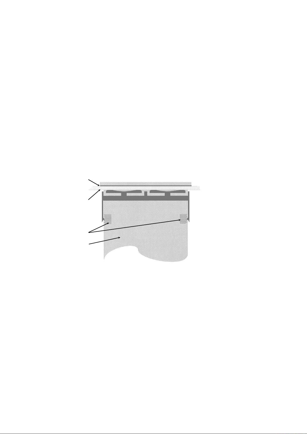
Gasket
Mounting Panel
Clamp
Ratchets
Instrument
Housing
Slide mounting clamp over
the instrument housing
towards rear face of
mounting panel until the
tongues engage in ratchets
and instrument is clamped in
position.
Hold instrument firmly in
position (apply pressure to
bezel only)
Instruments may be mounted side-by-side in a multiple installation, but instrument to panel
moisture and dust sealing will be compromised. Allow a 20mm gap above, below and behind
the instrument for ventilation. The cut-out width (for n instruments) is:
(96n - 4) mm or (3.78n - 0.16) inches
If panel sealing must be maintained, mount each instrument into an individual cut-out with
6mm or more clearance between the edges of the holes.
Note:
The mounting clamp tongues may engage the ratchets either on the sides or the
top/bottom faces of the Instrument housing. When installing several Instruments side-byside in one cut-out, use the ratchets on the top/bottom faces.
CAUTION:
Ensure the inside of the panel remains within the instrument operating temperature
and that there is adequate airflow to prevent overheating.
CAUTION:
Do not remove the panel gasket, as this may result in inadequate clamping and
sealing of the instrument to the panel.
Once the instrument is installed in its mounting panel, it may be subsequently removed from
it’s housing, if necessary, as described in the Fitting and Removing Option Modules section.
Cleaning
Clean the front panel by washing with warm soapy water and dry immediately If the USB
option is fitted, close the USB port cover before cleaning.
March 2012 Installation Page 17
Figure 2. Panel-Mounting the instrument
Page 17
BOARD
NUMBER
Single Relay Output for option slot 1
716/01
Single SSR Driver Output for option slot 1
716/02
Triac Output for option slot 1
716/03
Linear mA / Voltage Output module for option slot 1
639/01
Single Relay Output for option slot 2 or 3
717/01
Dual Relay Output for option slot 2 or 3
644/01
Single SSR Driver Output for option slot 2 or 3
717/02
Dual SSR Driver Output for option slot 2 or 3
644/02
Triac module Output for slot 2 or 3
647/01
Linear mA / Voltage Output for option slot 2 or 3
640/01
24VDC Transmitter Power Supply for option slot 2 or 3
642/01
Digital Input for option slot A
641/02
Basic Auxiliary Input for option slot A
653/01
RS485 Serial Communications for option slot A
680/01
Ethernet Communications for option slot A
707/01
Full Auxiliary Input (inc digital input B) for option slot B
641/01
4-Relay Output for option slot 4
703/01
PC Configuration Software & Lead
3 Field Upgrade Options
Options Modules and Functions
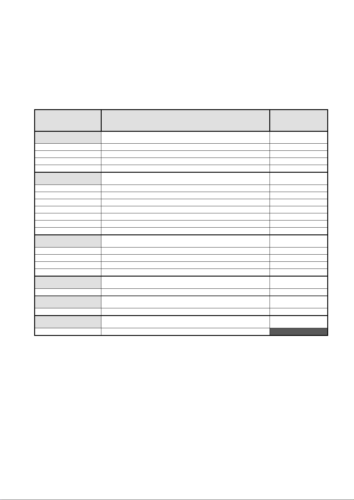
The available plug-in modules, options and accessories are shown in below:
Table 1. Options & Accessories
PART
NUMBER
OPTION SLOT 1
2300X-R1
2300X-DC1
2300X-T1
2300X-F1
OPTION SLOT 2 or 3
2300X-R2
2300X-R23
2300X-DC2
2300X-DC23
2300X-T2
2300X-F2
2300X-TPS
OPTION SLOT A
2300X-DI
2300X-RSP1
2300X-485
2300X-EI
OPTION SLOT B
2300X-RSPDI
DESCRIPTION
IDENTIFICATION
OPTION SLOT 4
2300X-R4
ACCESSORIES
CN2300-SOFT
Note:
Modules can be either pre-installed at the time of manufacture, or retrofitted in the field.
CAUTION:
Plastic pegs prevent fitting of older non-reinforced single relay modules (Board
Identification Numbers 637/01 and 638/01). Fitting the older relay modules reduces
the isolation rating to Basic 240V Isolation and is therefore not recommended.
Remove this peg when fitting Dual Relay Modules.
Note:
All dual relay modules have reinforced isolation.
March 2012 Field Upgrade Options Page 18
Page 18

Board Positions
Board Mounting Struts
Option 4 Module
Option A Module
Option 3 Module
Universal Input Board
Power Supply Board
Option B Module
Option 1 Module
(hidden below B)
Option 2 Module
Option C Module
Preparing to Install or Remove Options Modules
CAUTION:
Before removing the instrument from it’s housing, ensure that all power has been
removed from the rear terminals. Modules / boards should only be replaced by a
trained technician.
1. Remove the instrument from its housing by gripping the edges of the front panel (there is a
finger grip on each edge) and pull the instrument forwards. This will release the instrument
from the rear connectors in the housing and will give access to the boards.
2. Take note of the orientation of the instrument for subsequent replacement into the
housing. The positions of the boards in the instrument are shown above.
Figure 3. Rear view (uncased) & board positions
March 2012 Field Upgrade Options Page 19
Page 19

Main Board Connectors
POWER SUPPLY
BOARD
Transformer Colour
Code
100-240V (Yellow)
24-48V(Blue)
Display Board
Connections
UNIVERSAL INPUT
BOARD
Option 3 Slot
Connector PL4B
Option Slot A
Connectors PL5, & PL6
Option 1 Slot
Connectors PL7 & PL8
PC Configurator
Socket SK1
Option 2 Slot
Connector PL4A
Option Slot B
Connectors PL2A, PL2B &
PL2C
Removing/Replacing Option Modules
1. To remove or replace modules in Option Slots 1, 2, 3, A or B, it is necessary to detach the
2. Remove or fit the modules to the connectors on the Power Supply and Input boards. The
3. Assemble the Power Supply and Input boards together. Tongues on each option module
4. Remove or replace the Slot C and 4 modules as required.
5. Push the boards forward to ensure correct connection to the front Display/CPU board.
CAUTION:
Power Supply and Input boards from the front panel by lifting first the upper and then
lower mounting struts.
location of the connectors is shown below. Plastic pegs prevent fitting of older nonreinforced single relay modules – Remove the peg to fit dual relay modules
locate into a slots cut into the main boards, opposite each of the connectors. Hold the
Power and Input boards together and relocate them back on their mounting struts.
Check for correct orientation of the modules and that all pins are located correctly.
Figure 4. Main board connectors
Page 20 Field Upgrade Options March 2012
Page 20

Replacing the Instrument in its Housing
CAUTION:
Before replacing the instrument in it’s housing, ensure that all power has been
removed from the rear terminals.
With the required option modules correctly located into their respective positions the
instrument can be replaced into it’s housing as follows:
1. Hold the Power Supply and Input boards together.
2. Align the boards with the guides in the housing.
3. Slowly and firmly, push the instrument in position.
CAUTION:
Ensure that the instrument is correctly orientated. A mechanical stop will operate if
an attempt is made to insert the instrument in the wrong orientation, this stop MUST
NOT be over-ridden.
Auto Detection of Option Modules
The instrument automatically detects which option modules have been fitted into each slot.
The menus and screens change to reflect the options compatible with the hardware fitted.
The modules fitted can be viewed in the products information menu, as detailed in the
Product Information Mode section of this manual.
Replacement of Power Supply or Input Boards
It is recommend that users change these boards only if unavoidable.
1. Remove the instrument from it’s housing as detailed above.
2. Remove all option modules.
3. Replace the Power Supply or Input board as required. Carefully observe the transformer
colour and the case labelling to check the supply voltage when replacing the power
supply board.
4. Reassemble the unit in it’s case.
5. If the input board has to be replaced, a full recalibration must be carried out before the
instrument is used. Refer to the calibration section of this manual for instructions.
CAUTION:
Replacement of boards must be carried out by a trained technician.
If the Power Supply board does not match the labelling, users may apply incorrect
voltage resulting in irreparable damage.
March 2012 Field Upgrade Options Page 21
Page 21

Data Recorder Board
If installed, the Data Recorder memory and Real Time Clock (RTC) components are located
on a plug-in daughter board attached to the front Display/CPU board.
CAUTION:
Servicing of the Data Recorder/RTC circuit and replacement of the lithium battery
should only be carried out by a trained technician.
Profiler Enabling
If you purchased a controller with the Profiler option installed, these features will be enabled
during manufacture.
Controllers supplied without the Profiler option installed can be upgraded in the field by
purchasing a licence code number from your supplier. A unique code must be purchased to
enable profiling on each controller that requires it.
Entering the Profiler Enable Code
Hold down the and keys during the power-up “splash screen”.
Using the or keys, enter the 16-character licence code in the displayed screen.
Press to move on to the next character. Press to move back to the previous
character.
Press after entering the final character.
To confirm if profiling is installed in your instrument, check the Controller Feature Information
in Product Information mode.
Page 22 Field Upgrade Options March 2012
Page 22

4 Electrical Installation
CAUTION:
Installation should be only performed by technically competent personnel. It is the
responsibility of the installing engineer to ensure that the configuration is safe.
Local Regulations regarding electrical installation & safety must be observed (e.g.
US National Electrical Code (NEC) or Canadian Electrical Code).
Installation Considerations
Ignition transformers, arc welders, motor drives, mechanical contact relays and solenoids are
examples of devices that generate electrical noise in typical industrial environments. The
following guidelines MUST be followed to minimise their effects.
1. If the instrument is being installed in existing equipment, the wiring in the area should be
checked to ensure that good wiring practices have been followed.
2. Noise-generating devices such as those listed should be mounted in a separate
enclosure. If this is not possible, separate them from the instrument, by the largest
distance possible.
3. If possible, eliminate mechanical contact relays and replace with solid-state relays. If a
mechanical relay being powered by an output of this instrument cannot be replaced, a
solid-state relay can be used to isolate the instrument.
4. A separate isolation transformer to feed only the instrumentation should be considered.
The transformer can isolate the instrument from noise found on the AC power input.
AC Power Wiring - Neutral (for 100 to 240V AC versions)
It is good practice to ensure that the AC neutral is at or near ground (earth) potential. A
proper neutral will help ensure maximum performance from the instrument.
Wire Isolation
Four voltage levels of input and output wiring may be used with the unit:
1. Analogue input or output (for example thermocouple, RTD, VDC, mVDC or mADC)
2. Relays & Triac outputs
3. SSR Driver outputs
4. AC power
CAUTION:
The only wires that should run together are those of the same category.
If any wires need to run parallel with any other lines, maintain a minimum space of 150mm
between them.
If wires MUST cross each other, ensure they do so at 90 degrees to minimise interference.
March 2012 Electrical Installation Page 23
Page 23
Use of Shielded Cable
All analogue signals must use shielded cable. This will help eliminate electrical noise
induction on the wires. Connection lead length must be kept as short as possible keeping the
wires protected by the shielding. The shield should be grounded at one end only. The
preferred grounding location is at the sensor, transmitter or transducer.
Noise Suppression at Source
Usually when good wiring practices are followed, no further noise protection is necessary.
Sometimes in severe electrical environments, the amount of noise is so great that it has to be
suppressed at source. Many manufacturers of relays, contactors etc supply 'surge
suppressors' which mount on the noise source. For those devices that do not have surge
suppressors supplied, Resistance-Capacitance (RC) networks and/or Metal Oxide Varistors
(MOV) may be added.
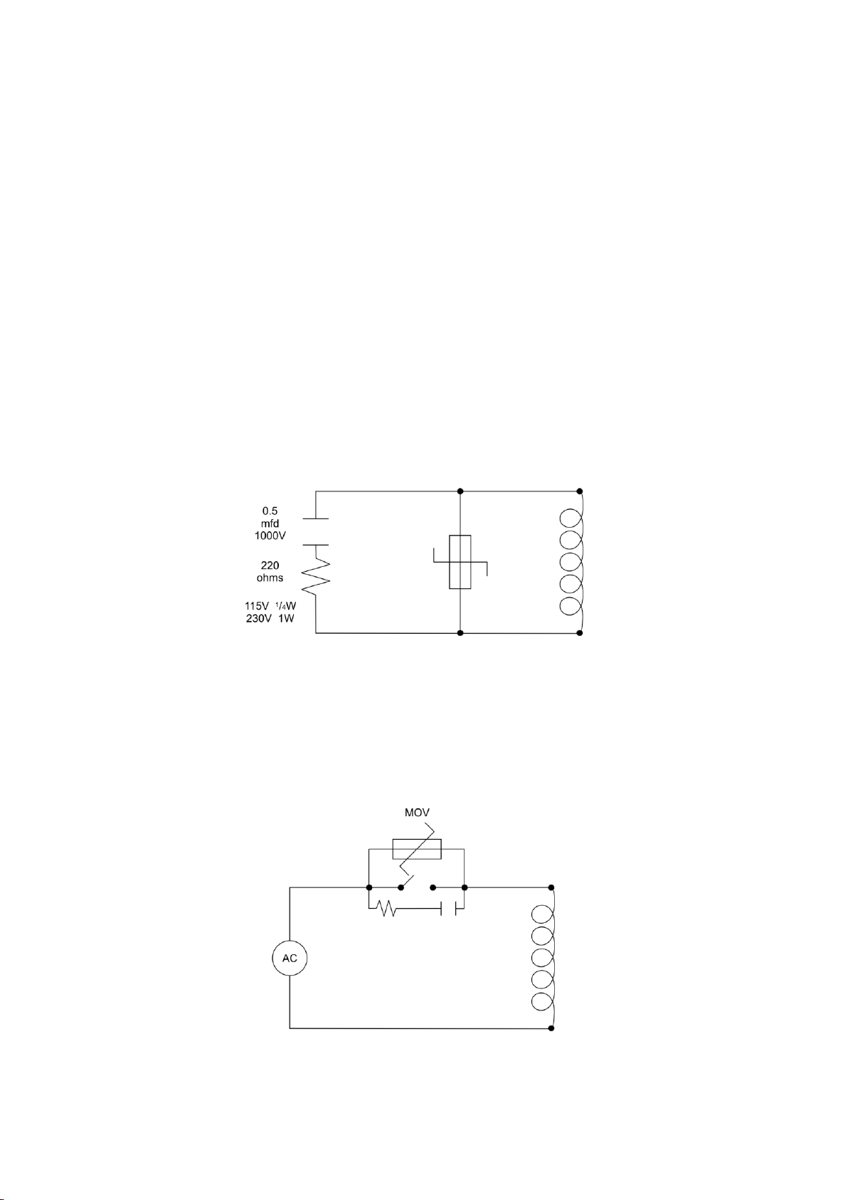
Inductive coils:- MOVs are recommended for transient suppression in inductive coils,
connected in parallel and as close as possible to the coil. Additional protection may be
provided by adding an RC network across the MOV.
Figure 5. Transient suppression with inductive coils
Contacts:- Arcing may occur across contacts when they open and close. This results in
electrical noise as well as damage to the contacts. Connecting a properly sized RC network
can eliminate this arc.
For circuits up to 3 amps, a combination of a 47 ohm resistor and 0.1 microfarad capacitor
(1000 volts) is recommended. For circuits from 3 to 5 amps, connect two of these in parallel.
Figure 6. Contact noise suppression
Page 24 Electrical Installation March 2012
Page 24
Type
International
IEC584-3
USA ANSI
MC 96.1
British
BS1843
French
NFC 42-324
German
DIN 43710
J
+*
Black
Black
White
Black
Yellow
Black
Yellow
Black
Red
Blue
-
White
Red
Blue
Black
Blue
T
+
Brown
Brown
Blue
Blue
White
Blue
Yellow
Blue
Red
Brown
-
White
Red
Blue
Blue
Brown
K
+
Green
Green
Yellow
Yellow
Brown
Red
Yellow
Yellow
Red
Green
-*
White
Red
Blue
Purple
Green
N
+
Pink
Pink
Orange
Orange
Orange
Orange
-
White
Red
Blue
B
+
Grey
Grey
Grey
Grey
Red
Grey
-
White
Red
Grey
R & S
+
Orange
Orange
Black
Green
White
Green
Yellow
Green
Red
White
-
White
Red
Blue
Green
White
C (W5)
+
White
White
-
Red
+ Wire
Sheath
- Wire
Sensor Placement (Thermocouple or RTD)
If the temperature probe is to be subjected to corrosive or abrasive conditions, it must be
protected by an appropriate thermowell. The probe must be positioned to reflect true process
temperature:
1. In a liquid media - the most agitated area
2. In air - the best circulated area
CAUTION:
The placement of probes into pipe work some distance from the heating vessel
leads to transport delay, which results in poor control.
For a two wire RTD, a wire link should be used in place of the third wire (see the wiring
section for details). Two wire RTDs should only be used with lead lengths less than 3 metres.
Use of three wire RTDs is strongly recommended to reduce errors do to lead resistance.
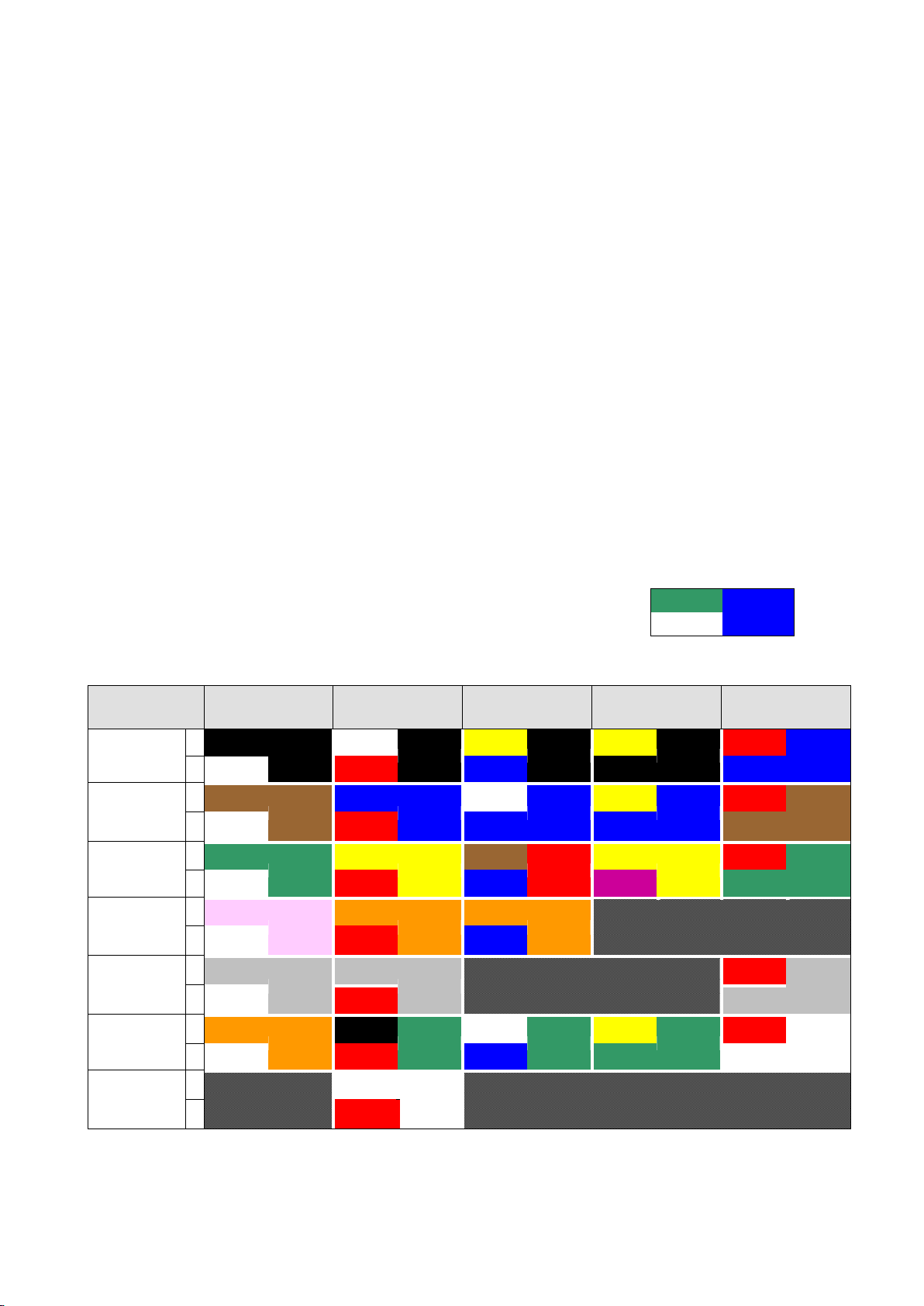
Thermocouple Wire Identification Chart
The different thermocouple types are identified by their wires colour, and where possible, the
outer insulation as well. There are several standards in use throughout the world.
The table below shows the wire and sheath colours used for most
common thermocouple types. The format used in this table is:
Table 2. Thermocouple Extension Wire Colours
Note:
March 2012 Electrical Installation Page 25
* = Wire is magnetic
Page 25

Connections and Wiring
This symbol means the equipment is protected throughout by double insulation.
CAUTION:
All external circuits connected must provide double insulation. Failure to comply
with the installation instructions may impact the protection provided by the unit.
WARNING:
TO AVOID ELECTRICAL SHOCK, AC POWER WIRING MUST NOT BE CONNECTED TO THE
SOURCE DISTRIBUTION PANEL UNTIL ALL WIRING PROCEDURES ARE COMPLETED.
CHECK THE INFORMATION LABEL ON THE CASE TO DETERMINE THE CORRECT
VOLTAGE BEFORE CONNECTING TO A LIVE SUPPLY.
Note:
The wiring diagram below shows all possible combinations to the main connections
(numbered 1 to 24) in the centre of the case rear. The actual connections required depend
upon the features available on the model and the modules and options fitted.
Figure 7. Main Rear terminals
Note:
Page 26 Electrical Installation March 2012
Page 26
13
14
L
N
The wiring diagram below shows the additional connections (numbered 25 to 42) at the
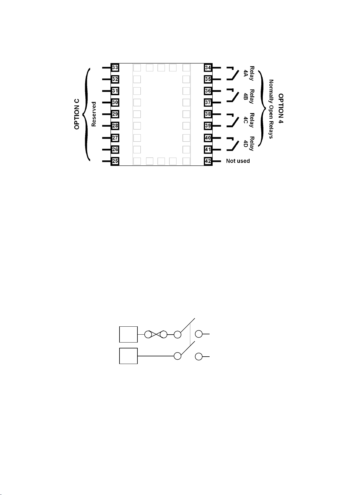
sides of the case rear. These are required for Options Slots 4 and C if fitted.
Figure 8. Additional Option terminals
Note:
Use single strand (1.2mm / AWG18 max size) copper wire throughout, except for the
thermocouple input, where the correct thermocouple or compensating cable and
connectors must be used.
Power Connections
Power Connections - Mains Powered Instruments
Mains powered instruments operate from a 100 to 240V (±10%) 50/60Hz supply. Power
consumption is 24VA. Connect the line voltage (live and neutral) as illustrated via a two-pole
IEC60947-1 & IEC60947-3 compliant isolation switch / circuit breaker and a UL listed fuse
type: 250V AC 1Amp anti-surge. If the instrument has relay outputs with contacts carrying
mains voltage, it is recommended that the relay contacts supply should be switched and
fused in a similar manner, but should be separate from the instruments mains supply.
Figure 9. Mains Power Connections
WARNING:
CHECK THE INFORMATION LABEL ON THE CASE TO DETERMINE THE CORRECT
VOLTAGE BEFORE CONNECTING TO A LIVE SUPPLY.
CAUTION:
This equipment is designed for installation in an enclosure that provides adequate
protection against electric shock. The isolation switch should be located in close
proximity to the unit, in easy reach of the operator and appropriately marked.
March 2012 Electrical Installation Page 27
Page 27
Power Connections - 24/48V AC/DC Powered Instruments
13
14
_
+
3
2
+
_
24/48V AD/DC powered instruments will operate from a 20 to 48V AC or 22 to 55V DC
supply. AC power consumption is 15VA max, DC power consumption is 12 watts max.
Connection should be via a two-pole IEC60947-1 & IEC60947-3 compliant isolation switch /
circuit breaker and a UL listed fuse type: 65v dc 1Aamp anti-surge.
Figure 10. 24/48V AC/DC Power Connections
WARNING:
CHECK THE INFORMATION LABEL ON THE CASE TO DETERMINE THE CORRECT
VOLTAGE BEFORE CONNECTING TO A LIVE SUPPLY.
CAUTION:
This equipment is designed for installation in an enclosure that provides adequate
protection against electric shock. The isolation switch should be located in close
proximity to the unit, in easy reach of the operator and appropriately marked.
Universal Input Connections
Universal Input Connections - Thermocouple (T/C)
Use only the correct thermocouple wire or compensating cable from the probe to the
instrument terminals avoiding joints in the cable if possible. Where joints are made, special
thermocouple connectors must be used. Failure to use the correct wire type and connectors
will lead to inaccurate readings. Ensure correct polarity of the wires by cross-referencing the
colours with a thermocouple reference table.
Figure 11. Thermocouple Input Connections
Page 28 Electrical Installation March 2012
Page 28
RTD
3
2
1
+
_
_
+
mA
mV/V
3
2
1
Universal Input Connections – PT100 / NI120 (RTD) input
For three wire RTDs, connect the resistive leg and the common legs of the RTD as
illustrated. For a two wire RTD a wire link should be used in place of the third wire (shown by
dotted line). Two wire RTDs should only be used when the leads are less than 3 metres long.
Avoid cable joints.
Figure 12. RTD Input Connections
Four wire RTDs can be used, provided that the fourth wire is left unconnected. This wire
should be cut short or tied back so that it cannot contact any of the terminals on the rear of
the instrument.
Universal Input Connections - Linear Volt, mV or mA input
Linear DC voltage, millivolt or milliamp input connections are made as illustrated. Carefully
observe the polarity of the connections.
Figure 13. DC Volt, mV & mA Input Connections
March 2012 Electrical Installation Page 29
Page 29

Option Slot 1 Connections
19
20
N/C
COM
21
N/O
19
20
_
21
+
20
21
Option Slot 1 – Single Relay Output Module
If option slot 1 is fitted with a single relay output module, make connections as illustrated.
The relay contacts are SPDT and rated at 2 amps resistive, 240 VAC.
Figure 14. Option Slot 1 – Single Relay Module
Option Slot 1 – Single SSR Driver Output Module
If option slot 1 is fitted with a single SSR driver output module, make connections as
illustrated. The solid-state relay driver is a 0-10V DC signal, load impedance must be no less
than 500 ohms. SSR driver outputs are not isolated from the signal input or other SSR driver
outputs.
Figure 15. Option Slot 1 – Single SSR Driver Module
Option Slot 1 - Triac Output Module
If option slot 1 is fitted with a Triac output module, make connections as shown. This output
is rated at 0.01 to 1 amp @ 280V AC 50/60Hz. A snubber should be fitted across inductive
loads to ensure reliable switch off the Triac.
Figure 16. Option Slot 1 - Triac Module
Page 30 Electrical Installation March 2012
Page 30

19
20
_
21
+
22
23
N/C
COM
24
N/O
22
23
N/O OUTPUT 2B
COMMON
24
N/O OUTPUT 2A
Option Slot 1 - Linear Voltage or mADC Output module
If option slot 1 is fitted with a DC linear output module, make connections as illustrated.
Figure 17. Option Slot 1 - Linear Voltage & mADC Module
Option Slot 2 Connections
Option Slot 2 – Single Relay Output Module
If option slot 2 is fitted with a single relay output module, make connections as illustrated.
The relay contacts are SPDT, and rated at 2 amps resistive, 240 VAC.
Figure 18. Option Slot 2 – Single Relay Module
Option Slot 2 - Dual Relay Output Module
If option slot 2 is fitted with a dual relay output module, make connections as illustrated. This
module has two independent SPST relays, which share a common connection terminal. The
contacts are rated at 2 amp resistive 240 VAC.
March 2012 Electrical Installation Page 31
Figure 19. Option Slot 2 - Dual Relay Module
Page 31

Option Slot 2 – Single SSR Driver Output Module
22
23
_
24
+
23
24
22
23
- OUTPUT 2A
- OUTPUT 2B
24
+ COMMON
If option slot 2 is fitted with a single SSR driver output module, make connections as
illustrated. The solid-state relay driver is a 0-10V DC signal, load impedance must be no less
than 500 ohms. SSR driver outputs are not isolated from the signal input or other SSR driver
outputs.
Figure 20. Option Slot 2 – Single SSR Driver Module
Option Slot 2 – Dual SSR Driver Output Module
If option slot 2 is fitted with a dual SSR driver output module, make connections as
illustrated. The solid-state relay drivers are a 0-10V DC signal, load impedance must be no
less than 500 ohms. SSR driver outputs are not isolated from the signal input or other SSR
driver outputs.
Figure 21. Option Slot 2 – Dual SSR Driver Module
Option Slot 2 - Triac Output Module
If option slot 2 is fitted with a Triac output module, make connections as shown. This output
is rated at 0.01 to 1 amp @ 280V AC 50/60Hz. A snubber should be fitted across inductive
loads to ensure reliable switch off the Triac.
Page 32 Electrical Installation March 2012
Figure 22. Option Slot 2 - Triac Module
Page 32

22
23 _ 24
+
22
23 _ 24
+
10
11
N/C
COM
12
N/O
Option Slot 2 - Linear Voltage or mADC Output module
If option slot 2 is fitted with a DC linear output module, make connections as illustrated.
Figure 23. Option Slot 2 - Linear Voltage & mADC module
Option Slot 2 - Transmitter Power Supply Module
If option slot 2 is fitted with a transmitter power supply module, make connections as
illustrated. The output is an unregulated 24V DC, 22mA supply.
Figure 24. Option Slot 2 - Transmitter Power Supply Module
Option Slot 3 Connections
Option Slot 3 – Single Relay Output Module
If option slot 3 is fitted with a single relay output module, make connections as illustrated.
The relay contacts are SPDT, and rated at 2 amps resistive, 240 VAC.
Figure 25. Option Slot 3 – Single Relay Module
March 2012 Electrical Installation Page 33
Page 33

Option Slot 3 - Dual Relay Output Module
10
11 _ 12
+
10
11
N/O OUTPUT 3B
COMMON
12
N/O OUTPUT 3A
If option slot 3 is fitted with a dual relay output module, make connections as illustrated. This
module has two independent SPST relays, which share a common connection terminal. The
contacts are rated at 2 amp resistive 240 VAC.
Figure 26. Option Slot 3 - Dual Relay Module
Option Slot 3 – Single SSR Driver Output Module
If option slot 3 is fitted with a single SSR driver output module, make connections as
illustrated. The solid-state relay driver is a 0-10V DC signal, load impedance must be no less
than 500 ohms. SSR driver outputs are not isolated from the signal input or other SSR driver
outputs.
Figure 27. Option Slot 3 – Single SSR Driver Module
Page 34 Electrical Installation March 2012
Page 34

10
11
_
12
+
10
11
10
11
- OUTPUT 3A
- OUTPUT 3B
12
+ COMMON
Option Slot 3 – Dual SSR Driver Output Module
If option slot 3 is fitted with a dual SSR driver output module, make connections as
illustrated. The solid-state relay drivers are a 0-10V DC signal, load impedance must be no
less than 500 ohms. SSR driver outputs are not isolated from the signal input or other SSR
driver outputs.
Figure 28. Option Slot 3 – Dual SSR Driver Module
Option Slot 3 - Triac Output Module
If option slot 3 is fitted with a Triac output module, make connections as shown. This output
is rated at 0.01 to 1 amp @ 280V AC 50/60Hz. A snubber should be fitted across inductive
loads to ensure reliable switch off the Triac.
Figure 29. Option Slot 3 - Triac Module
Option Slot 3 - Linear Voltage or mADC Output module
If option slot 3 is fitted with a DC linear output module, make connections as illustrated.
March 2012 Electrical Installation Page 35
Figure 30. Option Slot 3 - Linear Voltage & mADC module
Page 35

34
N/O OUTPUT 4A
35
COM OUTPUT 4A
36
N/O OUTPUT 4B
37
COM OUTPUT 4B
38
N/O OUTPUT 4C
39
COM OUTPUT 4C
40
N/O OUTPUT 4D
41
COM OUTPUT 4D
42
UNUSED
Option Slot 3 - Transmitter Power Supply Module
10
11
_
12
+
If option slot 3 is fitted with a transmitter power supply module, make connections as
illustrated. The output is an unregulated 24V DC, 22mA supply.
Figure 31. Option Slot 3 - Transmitter Power Supply Module
Option Slot 4 Connections
Option Slot 4 – Quad Relay Module
If option slot 4 is fitted with a quad relay module, make connections as illustrated. This
module has four independent SPST relays. The contacts are rated at 2 amp resistive 240
VAC.
Page 36 Electrical Installation March 2012
Figure 32. Option Slot 4 – Quad Relay Module
Page 36
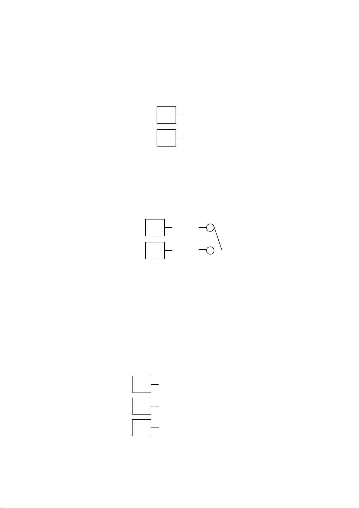
RS485
16
17
18
COM
16
17
_
+
16
17
_
+
Option Slot A Connections
Option Slot A Connections – Basic Auxiliary Input Module
If option slot A is fitted with a basic auxiliary input module, connect as shown. Consider using
the full auxiliary input (Option Slot B) instead, as this has additional features and leaves
option slot A free for other modules.
Figure 33. Option Slot A – Basic Auxiliary Input Module
Option Slot A Connections - Digital Input A Module
If a digital input module is fitted in option slot A, this may be connected to either voltage free
contacts (e.g. switch or relay), or a TTL compatible voltage. Connections are shown below.
Figure 34. Option Slot A – Digital Input A Module
Option Slot A Connections - Ethernet Communications Module
If option slot A is fitted with the Ethernet communication module, a standard RJ45 connector
is accessible from the top of case. No rear connections are required.
Option Slot A Connections - RS485 Serial Communications Module
If option slot A is fitted with the RS485 serial communication module, connections are as
illustrated. Carefully observe the polarity of the A (Rx/Tx +ve) and B (Rx/Tx -ve) connections.
Figure 35. Option Slot A – RS485 Serial Communications Module
CAUTION:
March 2012 Electrical Installation Page 37
Page 37
External computing devices connected to the communications port should comply
9
8
_
+
7
6
5
(or Pot Low)
_ + (or Pot Wiper)
(or Pot High)
with the standard, UL 60950.
Option Slot B Connections
Option Slot B Connections – Digital Input B (Full Auxiliary Module)
If option slot B is fitted with the Full Auxiliary input module (see below), a secondary digital
input is also provided. This may be connected to the voltage free contacts of a switch or
relay, or to a TTL compatible voltage.
Figure 36. Option Slot B – Digital Input B Connections
Option Slot B Connections – Full Auxiliary Input B Module
If option slot B is fitted with full auxiliary input feature, input connections are as shown.
Figure 37. Option Slot B – Full Auxiliary Input Connections
Page 38 Electrical Installation March 2012
Page 38

5 Powering Up
CAUTION:
Ensure safe wiring practices have been followed. When powering up for the first
time, disconnect the output connections.
The instrument must be powered from a supply according to the wiring label on the side of
the unit. The supply will be either 100 to 240V AC, or 24/48V AC/DC powered. Check
carefully the supply voltage and connections before applying power.
Powering Up Procedure
At power up, a self-test procedure is automatically started, during which a splash screen is
displayed and the LED indicators are lit. At the first power up from new, or if the option
modules are changed, the Setup Wizard will run, indicating that configuration is required
(refer to the Setup Wizard section of this manual). At all other times, the instrument returns to
Operation Mode once the self-test procedure is complete.
Front Panel Overview
The illustration below shows the instrument front panel. A USB socket fitted to USB and Data
Recorder versions, to the right of the keypad.
Clean the front panel by washing with warm soapy water and dry immediately If the USB
option is fitted, close the USB port cover before cleaning.
Figure 38. Front panel and keys
Display
The instrument has a 160 x 80 pixel monochrome graphical display with dual colour
(red/green) backlight. The main display typically shows the process variable and setpoint
values or a graphical trend during normal operation. There are various bar graph, recorder
status and profile status information options (refer to the Display Configuration section for
more details). The top line of the display has labels for the 4 LED indicators. If desired, the
backlight colour can be changed to indicate the presence of an active alarm.
March 2012 Powering Up Page 39
Page 39
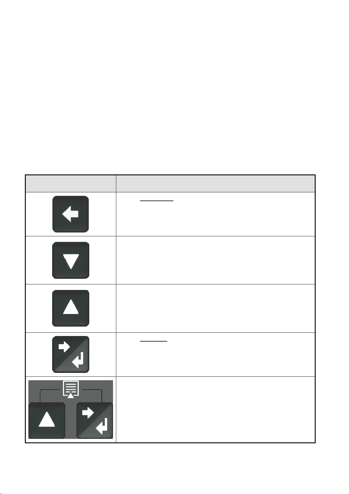
LED Functions
Button
Function
Moves backwards to the previous parameter or screen in the
current mode.
CAUTION: If editing a parameter, ensure that the current
(highlighted) parameter value is correct before pressing the key as
this action will update the instrument to the value displayed.
In menus and configuration choice screens, this key moves to the
next item on the list.
Editable values can be decreased by pressing this key. Holding the
key down speeds up the change.
In Trend view this key moves the Cursor Line back through the
stored data points
In menus and configuration choice screens, this key moves to the
previous item on the list.
Editable values can be increased by pressing this key. Holding the
key down speeds up the change.
In Trend view this key moves the Cursor Line forward through the
stored data points
Moves forwards to the next parameter or screen in the current
mode.
CAUTION: If editing a parameter, ensure that the current
(highlighted) parameter value is correct before pressing the key as
this action will update the instrument to the value displayed.
Pressing the key while holding down the key causes the
instrument to move up one menu level. From Operation Mode and
in most menus, this will result in entry to the Main Menu.
From sub-menus, it is necessary to carry out this sequence more
than once to reach the main menu.
CAUTION: If editing a parameter, ensure that the current
(highlighted) parameter value is correct before pressing the key as
this action will update the instrument to the value displayed.
There are four red LEDs that by default, indicate the status of the primary and secondary
control outputs, automatic tuning and alarm status. The top line of the graphical display has
four labels for LED indicators. The function of these LEDs and their display labels can be
changed using the PC configuration software. The information in this manual assumes
standard functions for these LEDs.
Keypad
Each instrument has four keypad switches, which are used to navigate through the user
menus and adjust the parameter values. In configuration screens, a context sensitive
scrolling help text is displayed that guides the user about the function of the keys.
Table 3. Keypad button functions
Page 40 Powering Up March 2012
Page 40

6 Messages and Error Indications
Start-up Errors
The following displays are shown when an error detected during the power-up self-test.
Option Module Problems
The “Option Slot n Error” display is shown when an error detected with the installed option
modules - where “n” is the slot number for the fault.
Replace the module in slot “n”. If this does not solve the problem, return the instrument for
servicing.
Configuration Problem
Warns if a problem has been detected with the instrument configuration. Check all settings
are correct before proceeding. If the problem persists, return the instrument for servicing.
Input Problems
Sensor Break Detection
Whenever a problem is detected with the process variable or auxiliary input connections,
their displayed value is replaced with the word “OPEN”.
This may be the result of a failed sensor, a broken connection or an input circuit fault.
In this condition, the Control Outputs go to the pre-set power value (see Control
Configuration).
CAUTION:
Correct the signal/wiring problem to continue normal operation.
Un-Calibrated Input Detection
The instrument is fully calibrated during manufacture. If a fault occurs and the calibration
data becomes corrupted, the process input display is replaced with the word “ERROR”.
In this condition, the Control Outputs go to the pre-set power value (see Control
Configuration).
CAUTION:
Re-calibrate the input before continuing normal operation. If the problem persists,
return the instrument for servicing.
March 2012 Messages and Error Indications Page 41
Page 41

PV Over-range or Under-range Indication
If the measured process variable value is more than 5% above than the Scale Range Upper
Limit, its value is replace by the word “HIGH”.
If the measured process variable value is more than 5% below than the Scale Range Lower
Limit, its value is replace by the word “LOW”.
Auxiliary Input Over-range or Under-range Indication
If the auxiliary input (RSP) is more than 5% above than the Auxiliary Input Upper Limit, its
value is replace by the word “HIGH”.
If the auxiliary input (RSP) is more than 5% below than the Auxiliary Input Lower Limit, its
value is replace by the word “LOW”.
If you need to return your instrument for servicing, check the Service Information screen
(available from the main menu) or contact your supplier.
USB Data Transfer Problems
Data Transfer Failure message
If the instrument cannot successfully write to the USB memory stick, the message “Data
Transfer Failure” will be displayed. Check that there is adequate disk space on the memory
stick, then retry.
If the instrument cannot successfully read data from the USB memory stick, the message
“Data Transfer Failure” will also appear. Check that this operation would not cause the
maximum number of profiles and/or segments to be exceeded, then retry.
Getting Help
First Level Support
If the errors persist or other problems are encountered, refer your supplier for first level
support. This includes help with configuration, tuning, servicing and replacement modules.
Second Level Support
If your supplier is unable to assist or cannot be contacted, check the Service Information
Page (in Configuration Mode) for details of whom to contact.
Third Level Support
If further assistance is required, contact the nearest company from those listed on the back
page of this manual.
Page 42 Messages and Error Indications March 2012
Page 42
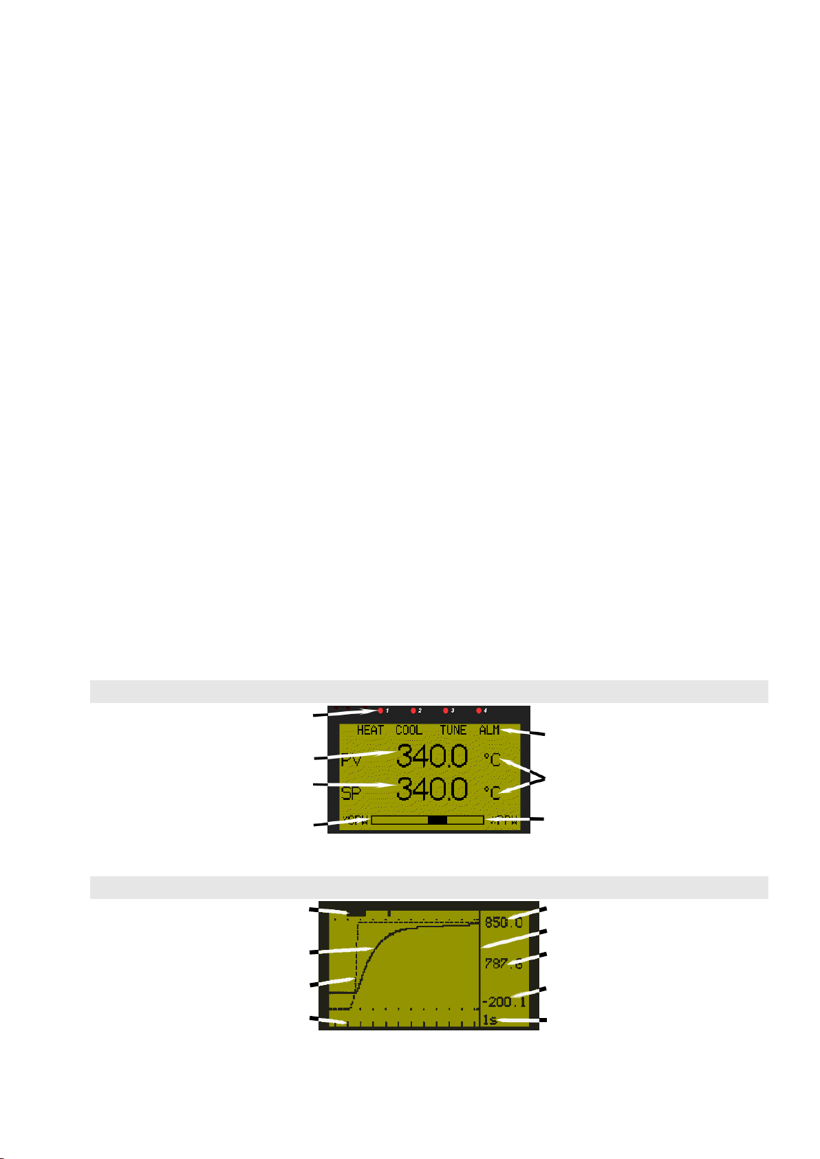
Example Base Operating Screen
LED Indicators
LED Function Labels
Process Variable Value
Engineering Units
Actual Setpoint Value
Secondary Power,
Memory remaining or
-ve Deviation Bar Graph
Primary Power,
Memory remaining or
+ve Deviation Bar Graph
Example Trend View Screen
Active Alarm(s)
Trend Upper Scale Value
Cursor Line
Process Variable Trend
PV Value At Cursor Line
Setpoint Trend (dotted)
Trend Lower Scale Value
Time Markers
(10 samples per marker)
Sample Interval
(or Time At Cursor Line)
7 Configuration and Use
Operation Mode
This is the mode used during normal operation of the instrument. It can be accessed from the
Main Menu, and is the usual mode entered at power-up. The available displays are
dependent upon the features and options fitted and the way in which it has been configured.
WARNING:
DURING NORMAL USE, THE USER MUST NOT REMOVE THE CONTROLLER FROM ITS
HOUSING OR HAVE UNRESTRICTED ACCESS TO THE REAR TERMINALS, AS THIS WOULD
PROVIDE POTENTIAL CONTACT WITH HAZARDOUS LIVE PARTS.
CAUTION:
Set all Configuration parameters as required before starting normal operations. It is
the responsibility of the installing engineer to ensure that the configuration is safe
for the intended application.
Base, Trend & Profile Operating Screens
The Base screen is the usual screen displayed during operation. It provides “at a glance”
information about the process. The Profile Operating screen shows similar information when
using profiles. Trend View is a graphical representation of recent process conditions. Its
scale adjusts automatically for the best resolution for the visible data.
Note:
Trend data is not retained at power down or if the Sample Interval is changed.
March 2012 Configuration & Use Page 43
Page 43
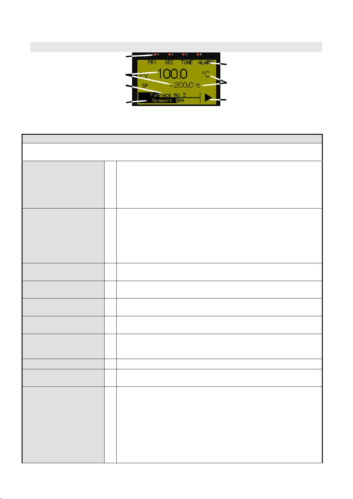
Example Profile Operating Screen
LED Indicators
LED Function Labels
Process Value & Setpoint
Engineering Units
Profile Name & Progress
Segment No. & Progress
Profile Status
► Run, ▌▌ Held, ■ Stopped
Operation Mode:
After 2 minutes without key activity, the most screens revert to the Base Operating Screen. Screens
marked do not revert automatically. They remain displayed until the user navigates away.
Calibration Check Due
Warning
Shown if a Calibration Reminder is set and the due date has passedif the feature is enabled in Control Configuration. Recorder version
only.
Shown at power up (and repeated once per day).
Press to acknowledge and continue using the instrument.
Re-calibrate or disable the reminder to cancel the warning.
Base Operating Screen.
Displayed is:
LED Labels; PV value;
SP value & Bar Graph
LED Labels = LED indicator functions. Defaults are HEAT, COOL,
TUNE & ALARM - can be altered with configuration software
PV value = The current Process Variable value.
SP value = The current Setpoint value.
Bar Graph = Primary/Secondary Power; Deviation or Memory Use. -
see Bar Graph Format screen in Display Configuration.
Auto/Manual Control
Mode Selection
Allows switching between automatic and manual control modes.
– only shown if enabled in Control Configuration.
Setpoint Value Display
& Adjustment
View and alter local (internal) setpoint(s) to any value between the
Setpoint Upper and Lower Limits. Remote setpoints are read only.
Setpoint Ramp Rate
Setpoint Ramp Rate adjustment between 0.1 and 9999.0 Display
Units per hour. - only shown if enabled in Control Configuration.
Select Setpoint Source
Select if Local Setpoint 1 or the Alternate Setpoint is to be the active
setpoint. - only shown if enabled in Control Configuration.
Control Enable
Enables or disables control outputs. When disabled, the unit works
normally except the Primary and Secondary Control Outputs are
turned off - only shown if enabled in Control Configuration.
Alarm Status
Shows the status (Active, Inactive or Unused) of the five alarms.
Event Status
Shows the status (Active or Inactive) of the five Events - Profiler
version only.
Profiler Operating
Screen
Displayed is:
LED Labels; PV value;
SP value; Bar Graph &
Status Indicator
LED Labels = LED indicator functions. Defaults are HEAT, COOL,
TUNE & ALARM - can be altered with configuration software
PV value = The current Process Variable value.
SP value = The current Setpoint value.
Bar Graph = The Profile Name & overall progress; the current
Segment Number and segment progress
Status Indicator = ► (Run), ▌▌ (Held), or ■ (Stopped).
- Profiler version only.
Table 4. Operation Mode Screens
Page 44 Configuration & Use March 2012
Page 44
Operator Profile Control
Allows the operator to control the defined profiles.
If a profile is running, the choices are: Do Nothing; Abort Profile (end
immediately); Jump to Next Segment; Hold Profile or Release Hold.
If no profile is running, the choices are: Do Nothing; Run Profile or
End Profile Control (returns to standard controller operation). - only
shown if enabled in the Profile Control Menu.
Profile Information
Shows the Profile Status (Running, Held, Aborted or Ended); Profile
Time Remaining, Cumulative Held Time; Cycles Completed and
Profile Sequences Completed - not shown when in Controller mode.
Segment Information
Shows the Current segment number and type (Ramp Up, Ramp
Down, Dwell, or End); Segment Time Remaining, Loops completed if
loop-back active- not shown when in Controller mode.
Start & Stop Data
Recording
Manually Stop or Start a new recording. – only shown if Recorder
Log Trigger is Operator Start/Stop.
Recorder Status
Information
The status of the data recorder. It shows if a recording is in progress;
the recording mode (FIFO or Record Until Memory Is Used); the
memory usage for each recording sample; memory remaining (in
bytes) and the approximate* recording time remaining.
*If the status of alarms is recorded, extra samples are taken when
these alarms change state. Therefore recording time will reduce.
Trend View
An auto-scaling trend graph of the Process Variable; Process
Variable & Setpoint (doted line), or the Minimum and Maximum value
of the Process Variable measured since the last sample. Any active
alarm(s) are indicated above the graph. 120 data points are visible.
The user can scroll the right hand cursor line back to examine up to
240 data points. The sample interval is set in Display Configuration.
Recorder Memory Full
Warning
Indicates that the Data Recorder memory is full and that recording
has stopped – Only if Recording mode is Record Until Memory Full.
- Custom Display
Screens
The user can copy up to 50 Configuration Menu parameters into
Operation Mode using the PC software.
Note: In this mode these screens are not pass-code protected.
Note:
The operator can freely use the screens in this mode, but it is possible to make the entire
Operation Mode “read only” from the Display Configuration sub-menu. This includes any
custom screens.
Navigating in Operator Mode
Press to move forward or to move backwards through the available screens.
When a displayed value can be adjusted, use or to change its value.
In Trend View, pressing or moves the Cursor Line back through the last 240
data points.
Adjusting the Local Setpoint(s)
Setpoints can be adjusted within the limits set by the Setpoint Upper and Lower Limit
parameters in Control Configuration. Operation Mode adjustment of Setpoint is not possible if
Read Only Operation Mode has been selected in the Display Configuration settings.
March 2012 Configuration & Use Page 45
Page 45

Press to select the Setpoint Value Display and Adjustment screen
Press or to adjust each Local Setpoint to the required value.
A Remote Setpoint value cannot be altered from the key pad.
Adjusting the Setpoint Ramp Rate
The Setpoint Ramp Rate may be adjusted in the range 0.1 to 9999.0 (in display units per
hour) and OFF. When the Setpoint Ramp Rate is set to Off, setpoint changes will step
immediately to the new value.
Press to select the Setpoint Ramp Rate screen
Press or to adjust ramp rate to the required value.
Note:
The SETPOINT ramp feature disables the pre-tune facility. The self-tune facility will
calculate new tuning terms only after the SETPOINT has completed the ramp.
Selecting Automatic or Manual Mode
Depending on the Control Configuration settings, an Auto/Manual selection screen may be
shown which allows operators to select between automatic or manual control. Switching to or
from manual mode is made via Bumpless Transfer. In Manual mode the Setpoint display is
replaced by a 0 to 100% power output level, labelled “Man”.
Press to select the Manual Power screen
Press or to adjust required power to the required value.
Note:
In Manual mode a running profile will hold until automatic control is reselected.
CAUTION:
The Manual Mode power level can be adjusted from 0 to 100% (-100 to +100% for
dual control). It is not restricted by the Output Power Limit parameters.
Control Enable or Disable
Depending on the Control Configuration settings, a Control Enable/Disable screen may be
shown. Disabling control turns off all control outputs (Primary and Secondary power output
levels are set to zero).
Press to select the Control Enable screen
Press or to change between control enable and disable.
CAUTION:
Use with care. The instrument is not able to control the process when control is
disabled. The Output Power Lower Limit parameters are also ignored.
Page 46 Configuration & Use March 2012
Page 46
Main Menu:
Operation Mode
Display of the process and setpoint values, selection/adjustment of
the Setpoints, auto/manual control, alarm/event status, trend view and
where available, data recorder and profile information.
Setup Wizard
Easy, step-by-step parameter setup for simple applications.
Supervisor Mode
If configured from the PC software, a sub-set of up to 50 Configuration
screens can be accessed.
Configuration Menu
Accesses the sub-menus for Input; Control; Outputs; Alarms;
Communications; Recorder; Clock; Display; Lock Codes and Reset
To Defaults menus and functions.
Automatic Tuning
Selection of Pre-Tune, Self-Tune and Auto Pre-Tune.
Profile Setup Menu
Setting of Global Control Parameters for all profiles; plus Profile
creation, editing and deletion.
Profile Control Menu
Selection of profiles. Running, holding or aborting the selected profile.
USB Menu
Uploading/downloading instrument configuration, profile information
and data recordings.
Recorder Menu
Manually starting, stopping and deleting recordings.
Product Information
Instrument information, including features and options installed.
Service Information
Contact information for service/support etc.
Main Menu
This menu is used to access the various features and configuration menus available in the
instrument. The available menus are dependent upon the features and options fitted and the
way in which it has been configured
Entry into the Main Menu
Holding down and pressing from Operation Mode and most other screens will
cause the unit to enter the Main Menu. Each time this key press sequence is made,
the instrument moves to the next menu level above. Sub-menu levels will require this
sequence to be pressed more than once in order to reach the Main Menu.
Navigating the Main Menu
Once in the Main Menu, press or to select the required option
Press to enter the chosen menu.
Scrolling “Help Text” is shown at the bottom of the screens to aid navigation.
Unlock Codes
To prevent unauthorised entry, most modes require a pass-code (1 to 9999) to gain entry.
These modes are indicated by the symbol against their names. The default unlock code
for all modes is 10 and the current codes can be viewed and changed from the Lock Code
View in Configuration Mode. For security, users should to change the codes. If the
Configuration Mode lock code is lost, refer to the Lock code View section of this manual.
Table 5. Main Menu Screens
March 2012 Configuration & Use Page 47
Page 47
Setup Wizard
Setup Wizard:
Setup Wizard Unlocking
w
Enter correct code number to access Setup Wizard.
- major screens from
Configuration Menu
(those marked w)
w
Press to select each major configuration parameter in turn. Follow
on-screen prompts to alter the values.
Setup Wizard
Completed
w
Confirms completion of the Setup Wizard. Exits to Operation Mode.
An easy Setup Wizard runs automatically at first ever power-up or if whenever a Reset To
Defaults is carried out. Users can follow the Wizard screens to setup parameters required for
typical applications (screens marked w in the following Screen Sequence lists are also
included in the Setup Wizard).
A partial Wizard also runs whenever option modules have been changed. The partial wizard,
only shows parameters affected by the changes made. The Wizard can also be run manually
from the Main Menu. Once completed, the Setup Wizard exits to Operation Mode.
Experts or users with more complex applications can select the parameters they wish to setup from the Configuration Menus instead of using the Wizard.
Manual entry to the Setup Wizard
CAUTION:
Adjustments to these parameters should only be performed by personnel
competent and authorised to do so.
The Setup Wizard can be selected from the Main Menu.
Hold down and press from to enter the Main Menu.
Press or to select Setup Wizard.
Press to enter the Setup Wizard.
Note:
With the exception of the first ever power-up, entry into this mode is security-protected by the
Setup Wizard Lock Code. Refer to the Lock Code View section for more details.
Navigating in the Setup Wizard
Press to move forward or to move backwards through the screens.
Press or to change the value as required.
Hold down and press to return to the Main Menu
Scrolling “Help Text” is shown at the bottom of the screens to aid navigation.
Table 6. Setup Wizard Screens
Page 48 Configuration & Use March 2012
Page 48
Supervisor Mode:
Supervisor Mode
Unlocking
If Supervisor Mode is configured, enter correct code number to
continue.
- Supervisor Mode
Screens …
Press to select each parameter in turn. Follow on-screen prompts
to alter the values.
Supervisor Mode
This mode is only available if it has been configured from the PC software. The software is
used to copy up to 50 screens from the Configuration Menus to include in Supervisor Mode.
The purpose of Supervisor Mode is to allow certain users access to a lock code protected
sub-set of the main configuration parameters without providing them with the higher level
Configuration Menu unlock code.
Entry into Supervisor Mode
CAUTION:
Adjustments to these parameters should only be performed by personnel
competent and authorised to do so.
Supervisor Mode is entered from the Main Menu
Hold down and press from to enter the Main Menu.
Press or to select Supervisor Mode
Press to enter the Supervisor Mode.
Note:
Entry into this mode is security-protected by the Supervisor Mode Lock Code. Refer to the
Lock Code View section for more details.
Navigating in Supervisor Mode
Press to move forward or to move backwards through the screens.
Press or to change the value as required.
Hold down and press to return to the Main Menu
Scrolling “Help Text” is shown at the bottom of the screens to aid navigation.
Table 7. Supervisor Mode Screens
March 2012 Configuration & Use Page 49
Page 49

Configuration Menu
Configuration Menu:
Configuration Mode
Unlocking
Enter correct code number to access Configuration Mode.
Configuration Options
Select the required Configuration Sub-Menu Option from: Input;
Control; Output; Alarm; Communications; Recorder; Clock; Display;
Lock Code or Reset To Defaults.
This menu can be used as an alternative to the more limited Setup Wizard when the
instrument is configured for the first time, or when further changes are required to the
instruments characteristics. Configuration contains a number of sub-menus that allow access
to all of the available parameters. The correct settings must be made before attempting to
use the instrument in an application. Screens marked w are also shown in the Easy Setup
Wizard.
Entry into the Configuration Menu
CAUTION:
Adjustments to these parameters should only be performed by personnel
competent and authorised to do so.
Configuration is entered from the Main Menu
Hold down and press from to enter the Main Menu.
Press or to select Configuration Menu
Press to enter the Configuration Menu.
Note:
Entry into this mode is security-protected by the Configuration Menu Lock Code. Refer to
the Unlock Code section for more details.
Navigating the Configuration Menu
Configuration contains sub-menus to set-up the Input; Output; Control; Alarm;
Communications; Recorder; Display and Lock Codes. There is also an option to return the
instrument to its factory default settings.
The correct settings must be made before attempting to use the instrument in an application.
From the Configuration Menu, press or to select the required sub-menu.
Press to enter the sub-menu.
Scrolling “Help Text” is shown at the bottom of the screens to aid navigation.
Note:
Only parameters that are applicable to the hardware and options fitted will be displayed.
Table 8. Configuration Menu Screens
Page 50 Configuration & Use March 2012
Page 50
Input Configuration Sub-Menu
Input Configuration:
Process Variable Input
Type
w
From various Thermocouple, RTD and Linear inputs. - see
specifications section for full details of input types available.
Engineering Units
w
Select display units from: °C; °F; °K; bar; %; %RH; pH; psi or none.
Decimal Point Position
w
Sets the maximum display resolution to 0; 1; 2 or 3 decimal places.
Temperature inputs are limited to 0 or 1 place. Numbers >99.999
never display more than 2 dec places, >999.99 never display more
than 1 dec place and >99999 always display without a decimal place.
Multi-Point Scaling
Enable
Enables or disables Linear Input Multi-Point Scaling. This feature
allows up to 15 point linearization of mA or V DC input signals.
Scale Range Lower
Limit
w
For Temperature inputs, Upper & Lower Limits set the usable span.
Min span = 100 units, max span = range limits - see specs. For
Linear inputs, Upper & Lower Limits define the values shown (-1999
to 9999) when input is at minimum and maximum values. Min span =
100 units. If Multi-Point Scaling is enabled, up to 15 breakpoints* can
scale input vs. displayed value between the linear input scale limits.
*A breakpoint set at 100% input ends the sequence.
Multi-Point Scale
Point(s)
Scale Range Upper
Limit
w
CJC Enable/Disable
Enables/disables internal Thermocouple Cold Junction
Compensation. If disabled, external compensation will be required for
thermocouples. The default value is Enabled.
Process Variable Offset
Trims the measured process value. +Ve values add to, –Ve values
subtract from measured input. Caution: A value other than zero
alters the apparent calibration of the instrument. Use with care!
Input Filter Time
Removes unwanted signal noise. Adjustable from 0.0 (OFF) to 100.0
seconds or OFF (default = 2s). Caution: Too large a value will cause
slow response to changes in the process. Use with care!
Auxiliary Input n Type
w
Sets the type of signal to be connected to the auxiliary inputs (if
fitted). From: 0-10V; 2-10V; 0-5V; 1-5V, 0-20mA or 4-20mA DC.
Auxiliary input B also supports >2K Potentiometer and 0-100mV.
Auxiliary Input n Scaling
Lower Limit
w
Scales the displayed a value (-9999 to 10000) when an auxiliary
input is at or below it’s lower limit (e.g. 4mA for a 4-20mA signal).
Auxiliary Input n Scaling
Upper Limit
w
Scales the displayed a value (-9999 to 10000) when an auxiliary
input is at or above it’s lower limit (e.g. 20mA for a 4-20mA signal).
Auxiliary Input n Offset
Trims the displayed a value for auxiliary input A or B. +Ve values are
added to, –Ve values subtracted from the measured auxiliary input.
Calibration Reminder
Enable/Disable
Enables or disables the display of Calibration Reminder at start-up
(repeated daily thereafter), if the due date has passed – Available on
the Recorder version only
Calibration Reminder
Due Date
Sets the due date for the Calibration Reminder - Available on the
Recorder version only
Table 9. Input Configuration Sub-Menu Screens
March 2012 Configuration & Use Page 51
Page 51
Control Configuration Sub-Menu
Control Configuration:
Control Enable/Disable
Sets the method used to enable/disable the control output(s). From:
Enabled (always); Disabled (always); Enable/Disable via Digital Input
A or B, or Operator Selectable (allows control output(s) to be turned
off from Operation Mode). Caution: The instrument is not able to
control the process when control is disabled. The Output Power
Lower Limit parameters are also ignored. Use with care!
Auto/Manual Mode
Access
w
Sets the method used to select Automatic or Manual Control. From:
Automatic (always); Manual (always); Select via Digital Input A or B,
or Operator Selectable (allows automatic or manual control to be
selected from Operation Mode). Caution: In Manual Mode, the user
must monitor and alter power to correctly control the process (0 to
100% or -100 to +100% for dual control). Manual power is not
restricted by the Output Power Limit parameters. Use with care!
Control Type
w
Set to Single Control for Primary control only (e.g. Heating or Cooling
only) or to Dual for Primary and Secondary Control outputs (e.g.
Heating & Cooling).
Primary Control Action
w
Set the Primary Control Output for Reverse or Direct Action. Reverse
action applies more primary power as the process falls further below
setpoint (e.g. heating applications). Direct action applies more
primary power as the process rises further above setpoint (e.g.
cooling applications).
If Dual Control is used, the secondary output action is always
opposite to the Primary action.
Control Status
Displays the current Process Variable and Setpoint values to aid
manual tuning – This screen is Read Only.
Power Output Level
Displays the current Primary and Secondary control power levels
(each 0 to 100%) to aid manual tuning – This screen is Read Only.
Primary Proportional
Band
Sets the width of the Primary Proportional Band between 0.5% and
999.9%, or select On-Off control. – This screen is Read Only during
automatic tuning.
Secondary Proportional
Band
Sets the width of the Secondary Proportional Band between 0.5%
and 999.9%, or select On-Off control. – This screen is Read Only
during automatic tuning.
Integral Time Constant
Sets the Integral Time Constant (Automatic Reset) from 1s to 99min
59s or OFF. – This screen is Read Only during automatic tuning.
Derivative Time
Constant
Derivative Time Constant (Rate) from 1s to 99 min 59s or OFF. –
This screen is Read Only during automatic tuning.
Manual Reset (Bias)
Sets the Manual Reset (Proportional Band Bias) from 0-100%
or -100 to +100% for Dual Control.
Overlap / Deadband
Sets the Overlap (+ve values) or Deadband (-ve values) between
Primary & Secondary Proportional Bands when Dual Control is used.
Primary On-Off
Differential
Sets the Primary On-Off control hysteresis (deadband) from 0.1 to
10.0% of Span (centred about setpoint), when Primary On-Off control
is used.
Table 10. Control Configuration Sub-Menu Screens
Page 52 Configuration & Use March 2012
Page 52
Secondary On-Off
Differential
Sets the Secondary On-Off control hysteresis (deadband) from 0.1 to
10.0% of Span (centred about setpoint), when Primary PID with
Secondary On-Off control is used.
Primary & Secondary
On-Off Differential
Sets the combined Primary & Secondary On-Off Control hysteresis
(deadband) from 0.1 to 10.0% of Span. when Primary On-Off control
and Secondary On-Off control is used.
Primary Cycle Time
Sets the Primary Power Cycle Time (0.5s to 512s). For time
proportioned Primary Relay, SSR Driver or Triac Control Outputs.
Secondary Cycle Time
Sets the Secondary Power Cycle Time (0.5s to 512s). For time
proportioned Secondary Relay, SSR Driver or Triac Control Outputs.
Primary Power Upper
Limit
Sets the Maximum Primary Output Power Limit, from 0 to 100% of
available power. This value must be higher than the lower limit.
Caution: The instrument will not be able to correctly control the
process if sufficient power isn’t available to maintain setpoint. Use
with care!
Primary Power Lower
Limit
Minimum Primary Output Power limit, from 0 to 100%. This value
must be less than the upper limit. Caution: The instrument will not
be able to correctly control the process if the lower limit is more than
required to maintain setpoint. Use with care!
Secondary Power Upper
Limit
Maximum Secondary Output Power limit, from 0 to 100%. This value
must be higher than the lower limit. Caution: The instrument will not
be able to correctly control the process if sufficient power isn’t
available to maintain setpoint. Use with care!
Secondary Power Lower
Limit
Minimum Secondary Output Power limit, from 0 to 100%. This value
must be less than the upper limit. Caution: The instrument will not
be able to correctly control the process if the lower limit is more than
required to maintain setpoint. Use with care!
Sensor Break Pre-set
Power Output
Sets the power level applied if the process input (or active RSP) is
lost. Adjustable from 0 to 100% or -100 to +100% for Dual Control.
The default value is OFF (0% power). Caution: Use a value that will
maintain safe conditions.
Setpoint Selection
w
Sets the method to select the Active Setpoint. From: Local
Setpoint 1 only; Alternate Setpoint only; Select via Digital Input A or
B; or Operator Selectable (allows Setpoint 1 or Alternate Setpoint to
be selected from Operation Mode).
Alternate Setpoint
Source
w
Up to two setpoints can be used, Local Setpoint 1 plus an Alternate
The Alternate Setpoint can be selected from: Local Setpoint 2 or a
Remote Setpoint set via Auxiliary Input A or B.
Setpoint Upper Limit
The maximum allowable setpoint value. Adjustable within the Input
Span limits, but must be greater than the Setpoint Lower Limit.
Applies to both local and remote setpoints. Caution: Operators can
adjust the setpoint to any value between the Setpoint Upper and
Lower Limits. Use with care!
Setpoint Lower Limit
The minimum allowable setpoint value. Adjustable within the Input
Span limits, but must be less than the Setpoint Upper Limit. Applies
to both local and remote setpoints. Caution: Operators can adjust
the setpoint to any value between the Setpoint Upper and Lower
Limits. Use with care!
Setpoint Ramp Editing
Enables or disables the changing of the Setpoint Ramp Rate in
Operation Mode – Note: this does not turn off an active ramp. To
turn of an active ramp, set the Setpoint Ramp Rate to OFF.
March 2012 Configuration & Use Page 53
Page 53
Setpoint Ramp Rate
The Setpoint Ramp Rate value (1 to 9999 display units per hour or
OFF). This ramp is applied at power-up and any setpoint changes.
Local Setpoint 1 Value
w
Sets the value of Local Setpoint 1 between the Setpoint Upper and
Lower Limits.
Local Setpoint 1 Offset
A value added to the Setpoint 1 value (+ve values) or subtracted
from it (-ve values). Use when the instrument is a slave in multi-zone
applications to achieve a zone offset. Otherwise, always set to zero.
Local Setpoint 2 Value
w
Sets the value of Local Setpoint 1 between the Setpoint Upper and
Lower Limits.
Local Setpoint 2 Offset
A value added to the Setpoint 2 value (+ve values) or subtracted
from it (-ve values). Use when the instrument is a slave in multi-zone
applications to achieve a zone offset. Otherwise, always set to zero.
Output Configuration Sub-Menu
Outputs Configuration:
No Outputs Warning
Shown if the Outputs Configuration menu is entered on an
instrument without any output modules fitted.
Linear Output n Type
w
Set the desired type for any Linear Outputs fitted. From: 0-5, 0-10,
1-5, 2-10V & 0-20, 4-20mA or 0-10VDC adjustable Transmitter PSU.
Adjustable 0-10V
Transmitter PSU n
w
Sets the voltage required if Linear Output n type is 0-10VDC
adjustable Transmitter PSU.
Output n Usage
w
Sets the use for each output fitted. From: Primary or Secondary
Control; Alarms; Profile Events & Alarms; Retransmit Process
Variable or Setpoint. Choices offered are as appropriate for the
output type fitted (e.g. only Linear Outputs can retransmit).
Output n Alarm
Selection
w
When an Output Usage is Alarms, this selects which alarm(s) will
cause it to change state. From Alarm 1; 2; 3; 4; 5 or a Logical OR of
alarms 1 to 2; 1 to 3; 1 to 4 or 1 to 5. Each choice is selectable with
Direct Action (on during alarm) or Reverse Action (off during alarm).
Output n Events
w
When an Output Usage is Events & Alarms, this selects which
Events(s) will cause it to change state. From: Profile Running or
Profile End; Event 1; 2; 3; 4; 5 or a Logical AND of Event n & Alarm
n. Each choice is selectable with Direct Action (on during event) or
Reverse Action (off during event). - Profiler version only
Retransmit Output n
Scale Low
w
Sets the displayed value at which a retransmission output should be
at it’s minimum level (e.g. the display value when a 4 to 20mA PV
Retransmission output will be 4mA. Adjustable from -1999 to 9999.
Retransmit Output n
Scale High
w
Sets the displayed value at which a retransmission output will be at
it’s maximum level (e.g. the display value when a 4 to 20mA PV
Retransmission output will be 20mA. Adjustable from -1999 to 9999.
Table 11. Output Configuration Sub-Menu Screens
Page 54 Configuration & Use March 2012
Page 54
Alarm Configuration Sub-Menu
Alarm Configuration:
Alarm n Type
w
Sets the type for each of the 5 alarms From: Unused; Process High;
Process Low; PV-SP Deviation; Band; Control Loop; Rate Of Signal
Change; PV Signal Break; Aux. Input A or B Break.
Alarm n Value
w
Alarm activation point. – applicable if type is High; Low; Deviation
(+ve above, -ve below SP), Band (above or below SP) or Rate of
Signal Change (a rate of more that x units per hour).
Process Alarm n
Hysteresis
Deadband on “safe” side of alarm, through which signal must pass
before alarm deactivates.
Signal Change Alarm n
Minimum Duration
The minimum time that the rate of input change must be above the
alarm threshold for a Rate Of Change Alarm to change state (from on
to off, or off to on). Adjustable from 1 to 9999 secs. Caution: If the
duration is less than this time, the alarm will not activate no matter
how fast the rate of rise.
Alarm n Inhibit
Enables or disables the prevention of initial alarm activation, if the
alarm condition is true at power up. Activation only occurs once the
alarm condition has passed and then reoccurred.
Loop Alarm Type
Sets the source of the Loop Alarm Time. From: Automatic (2x the
Integral Time Constant) or Manual (the Manual Loop Alarm Time
value). If configured, a Loop Alarm activates if no response is seen
after this time.
Manual Loop Alarm
Time
The time allowed after PID power output reaches minimum or
maximum), for process to begin responding.
Communications Configuration:
No Communications
Warning
If Communications Configuration menu is entered without a
communications module fitted.
Modbus RTU Parity
w
From: Odd; Even or None.
Modbus RTU Data Rate
w
From: 9600; 19200; 57600 or 115200 bps.
Master Mode, or Slave
Address
w
Slave address (1 to 255), or multi-zone Setpoint Master Mode.
Target Register In Slave
Target register for Setpoint value in attached slave controllers.
Master Mode Format
The data format required by the attached setpoint slaves. From:
Integer; integer with 1 decimal place or float.
Serial Communications
Write Enable
Enables/disables writing via RS485 or Ethernet (if fitted). When
disabled, all parameters are read only.
Table 12. Alarm Configuration Sub-Menu Screens
Communications Configuration Sub-Menu
Table 13. Communications Configuration Sub-Menu Screens
March 2012 Configuration & Use Page 55
Page 55
Recorder Configuration Sub-Menu
Recorder Configuration:
No Recorder Warning
If the Recorder Configuration menu is entered on an instrument
without this option fitted.
Recording In Progress
Warning
If recording in progress when Recorder Configuration entered. –
Allows access to the Recording Start/Stop screen only, until the
recording is stopped.
Recorder Mode
w
Choose Record Until Memory Used (Stop recording when full) or
Continuous FIFO (First In - First Out) - Caution: A FIFO recording
will overwrite all previous recordings in memory, starting with the
oldest data first. Download the previous data to USB memory stick
before selecting this option.
Recording Sample
Interval
w
A recording of the selected data will be taken once every Sample
Interval. From: Every 1; 2; 5; 10; 15; 30 Seconds, or Every 1; 2; 5;
10; 15; 30 Minutes. Note: Short intervals will reduce the maximum
possible duration of the recording.
Recorder Trigger
w
The recording Start/Stop trigger method to be used. From: Operation
Mode selection; Recorder Menu selection; On Alarm(s); Digital Input
A or B state; or During Profiles.
Trigger On Alarms
Any from: Alarm n – Where n is alarms 1 to 5. Any combination of
these can be set to trigger (TRG) or not (OFF). Any active alarm set
to TRG will start the instrument recording. Note: Recording will only
stop if all alarms selected as triggers become inactive.
Values To Record
Any from: Process Variable value; Maximum or Minimum PV (since
the previous sample was taken); Setpoint; Primary Power or
Secondary Power. Any combination of these can be set to Record
(REC) or not (OFF). Note: Recording more parameters will reduce
the maximum possible duration of the recording.
Alarms & System
Events To Record
Any from: Alarm n Status or Unit turned On/Off. Caution: An alarm
state change between samples is also recorded. This uses additional
recorder memory, which may cause the recording to end sooner than
expected.
Profiler Events To
Record
Any from: Profiler Event n Status. Caution: A profile event state
change between samples is also recorded. This uses additional
recorder memory, which may cause the recording to end sooner than
expected.
Recorder Status
Information
Shows if a recording is in progress; the recording mode; memory
usage per sample; memory remaining and the recording time
remaining. The time remaining is adjusted for any alarm/events that
have already occurred, but cannot allow for any future alarms/events
Table 14. Data Recorder Configuration Sub-Menu Screens
Page 56 Configuration & Use March 2012
Page 56
Clock Configuration Sub-Menu
Clock Configuration:
Date Format
w
Sets the format used for all displayed dates: dd/mm/yyyy (Day /
Month / Year) or mm/dd/yyyy (Month / Day / Year). – Recorder
versions only.
Set Date
w
Sets the internal clock Date. – Entered in the format defined by Date
Format screen. – Recorder versions only.
Set Day Of Week
Sets the day of week used by the internal clock. – Recorder versions
only.
Set Time
Sets the internal clock Time. - In hh:mm:ss (Hours : Minutes :
Seconds) format. – Recorder versions only.
Display Configuration:
Enable Custom Display
Mode
Enables/disables Custom Operation Mode, if configured (this mode
can only be enabled using the PC configuration software).
Read Only Operation
Mode?
Allows Operation Mode to be Read-Only or Read/Write. Screens can
be seen but values cannot be changed if set to Read-Only.
Operation Mode Bar
Graph Format
From: PID Power; Control Deviation or % Recorder Memory Usage.
Trend Sample Interval
Interval between display of next value on the trend graph From: Every
1; 2; 5; 10; 15; 30 Seconds, or Every 1; 2; 5; 10; 15; 30 Minutes.
Select Trend Mode
From: PV only, PV (solid) & SP (dotted) at sample time or Max/Min
PV between samples (candle-stick graph). Alarm activity is shown
above the trend graph.
Display Colour
From: Red only; Green only; Red to Green on Alarm or Green to Red
on Alarm.
Invert Display
Standard or Negative display image.
Display Contrast
Screen contrast (0 and 100) to improve clarity. 100 = maximum
contrast.
Language
Select English or the alternate local language. The alternate language
is selected at time of order. The choice of alternate language can be
changed using the PC software.
Table 15. Internal Clock Configuration Sub-Menu Screens
Display Configuration Sub-Menu
Table 16. Display Configuration Sub-Menu Screens
March 2012 Configuration & Use Page 57
Page 57
Lock Code View
Lock Code View:
Lock Code View 1
Setup Wizard; Configuration Mode and Tuning Menu Lock Codes
(1-9999 or OFF).
Lock Code View 2
Supervisor Mode; USB; Recorder and Profiler Menu Lock Codes
(1-9999 or OFF) - if fitted/configured.
Unlock Codes
To prevent unauthorised entry, some menus are protected by a lock code. These screens
are indicated by the symbol before their names in the screen list tables. To enter these
screens, the correct code must first be entered. The current lock codes can be viewed and
changed from the Lock Code View Configuration sub-menu.
The default unlock code for all protected menus is 10. For security, users are recommended
to change these codes. A value between 1 and 9999 can be used, or the lock can be set to
OFF if no protection is required.
Navigating Lock Code View
Press to move forward or to move backwards through the screen elements.
Press or to change the value as required.
Hold down and press to return to the Main Menu
Scrolling “Help Text” is shown at the bottom of the screens to aid navigation.
Table 17. Lock Code View Sub-Menu Screens
Lost Lock Codes
The lock codes can be viewed or changed from Configuration Mode. In the event that the
Configuration Mode lock code itself is forgotten, the instrument can be forced into Lock Code
View from power-up, where the codes can be checked or set to new values.
Forcing Lock Code View
Power down the instrument.
Re apply the power and hold down and for more than 5 seconds as the start-up
splash screen appears. Lock Code View will appear.
Press to move forward or to move backwards through the screen elements.
Make note of the codes or press or to change their values if required.
Hold down and press to return to the Main Menu
Scrolling “Help Text” is shown at the bottom of the screens to aid navigation.
Page 58 Configuration & Use March 2012
Page 58

Reset To Defaults:
Reset To Defaults
Sets all parameters to their factory default values.
Resetting To Defaults
Table 18. Reset To Defaults Sub-Menu Screen
If the instrument is to be used in a new or changed application, it is possible to reset all of the
instruments parameters back to their factory default settings. The Easy Setup Wizard runs
automatically whenever a Reset To Defaults is performed.
CAUTION:
User must reconfigure all required settings before using the instrument in a live
application.
Automatic Tuning Menu
The Automatic Tune Menu is used engage the Pre-tune and/or Self-tune facilities to assist
the user in setting up Proportional band(s), Integral and Derivative parameter values.
Pre-tune can be used to set PID parameters approximately. Self-tune may then be used to
optimise the tuning if required.
Pre-tune can be set to run automatically after every power-up by enabling Auto Pre-Tune.
The TUNE indicator (LED 3)* will flash while pre-tune is operating, and is continuously on
whilst Self-tune is operating. If both Pre-tune and Self-tune are engaged the AT indicator will
flash until Pre-tune is finished, and is then continuously on.
Note:
Self-Tune will not engage if either primary or secondary control outputs are set for On-Off
control.
Pre-Tune will not engage if either primary or secondary control outputs are set for On-Off
control, during setpoint ramping, if a profile is running or if the process variable is less than
5% of the input span from the setpoint.
Navigating Automatic Tuning Menu
Press to move forward or to move backwards through the selections.
Press or to engage or disengage the tuning as required.
Hold down and press to return to the Main Menu
Scrolling “Help Text” is shown at the bottom of the screens to aid navigation.
*Provided the function of LED3 has not been changed (LED functions can be altered using
the PC Configuration Software).
March 2012 Configuration & Use Page 59
Page 59
Table 19. Automatic Tuning Menus Screens
Automatic Tuning Menu:
Automatic Tuning Mode
Unlocking
Enter correct code number to access the Automatic Tuning Menu.
Pre-Tune
w
Turns Pre-Tune on/off. Pre-Tune is disabled in On-Off Control Mode;
if the PV is less than 5% of span from SP; during Profiles or if the
Setpoint is Ramping.
Pre-Tune Status
Shows the current Pre-Tune status. Active or Inactive.
Self-Tune
Turns Self-Tune on/off. Self-Tune is disabled in On-Off Control
Mode.
Self-Tune Status
Shows current Self-Tune status. Active or Inactive.
Auto Pre-Tune Enable
Enables/Disables Automatic Pre-Tune. When enabled, this attempts
to perform a Pre-Tune at every power-up. Normal Pre-Tune
engagement rules are applied (see Pre-Tune above).
Profiler Menu:
General
General Profile Configuration: Settings that apply to all profiles
Profile Run/Hold
Signal
Selects the method used to Run or Hold a profile. From: Digital Input
A; Digital Input B or Key Pad Only (using the either the Profile
Control Menu or an Operation Mode screen).
Profile Abort
Signal
Selects the method used to force a profile to end prematurely. From:
Digital Input A; Digital Input B or Key Pad Only (using either the
Profile Control Menu or an Operation Mode screen).
Control In
Operation Mode
Enables/disables the ability to control profiles (run, hold or abort)
from Operation Mode.
Enable Edit While
Running
Enables/disables the ability to edit profiles whist a profile is running
(even if selected, the current or next segment of the running profile
will not change until after the profile is restarted).
Create A Profile
Creates a new profile. A header is created first, followed by the
segments – see below. A warning is displayed if the maximum
number of 64 profiles or 255 segments is exceeded.
Profiler Setup Menu
Refer to the Profiler Option section of this manual for more details about the profiler features.
Screens marked will not time-out automatically. They must be completed for a valid profile
to be created.
Table 20. Profiler Setup Menu Screens
Page 60 Configuration & Use March 2012
Page 60
Profile Header Details
Profile Header: Settings that apply to the chosen profile as a whole
Enter Profile Name
Up to 16 characters can be used to name each profile
Profile Starting
Point
The setpoint value to be used at the beginning of the first segment.
From: Actual Setpoint or Process Variable value at the time the
profile starts.
Profile Start
Trigger
From: None (profile start is not delayed); After Delay or Day and
Time (Recorder version only).
Profile Start Time
The time (hh:mm:ss) when the profile should run. – This applies only
if Day and Time is the Profile Start Trigger. Caution: Take care not
to clash with other profiles. A Profile cannot start if another is
running.
Profile Start Day(s)
The Day(s) when the profile should run. From: Mon; Tue; Wed; Thu;
Fri; Sat; Sun; Mon-Fri; Mon-Sat; Sat-Sun or All. – This applies only if
Day and Time is the Profile Start Trigger.
Profile Start Delay
The delay time, up to 99:59 (hh:mm), for a profile to begin after the
start request has been given.
Profile Recovery
Method
The power-on action if profile was running at power-down (e.g. after
a power cut), or following correction of a signal break. From: Control
outputs off; Restart profile from the beginning; Maintain last profile
setpoint; Use controller setpoint; Continue profile from where it was
when power failed.
Profile Recovery
Time
The Recovery Method is ignored (the profile continues from where
power failed), if power off for less than this time. Max 99:59
(hh:mm). - Recorder version only.
Profile Abort
Action
Action after profile has been forced to stop before its end. From:
Control outputs off; Maintain last profile setpoint or Use controller
setpoint.
Profile Cycles
The number of times the program should run each time it is started
(1-9999 or Infinite).
Profile Segment Details
Profile Segments: Settings that apply to individual profile segments
Segment Number
Shows the number of the profile segment being created from 1-255
Segment Type
Set the segment type from: Ramp Time (time to reach target SP);
Ramp Rate (rate of change towards target SP); Step (jump to target
SP), Dwell (keep current SP); Hold (hold the profile until released);
Loop (back to a previous segment); Join (join to another profile);
End (end the profile) or Repeat Sequence Then End (repeat a
sequence of joined profiles – of which this is the last). A Join, End or
Repeat Sequence Then End will become the last segment in the
profile.
Segment Target
Setpoint
The setpoint value to be reached by the end of this segment, if the
segment type is Ramp Time, Ramp Rate or Step.
Segment Ramp
Time
The time (hh:mm:ss) to reach the Segment Target Setpoint if the
segment type is Ramp Time.
Segment Ramp
Rate
The rate of change towards the Segment Target Setpoint if the
segment type is Ramp Rate. The rate can be set from 0.001 to
9999.9 display units per hour.
Segment Dwell
Time
The time (hh:mm:ss) to maintain the current setpoint if the segment
type is Dwell.
March 2012 Configuration & Use Page 61
Page 61
Segment Details (Cont….)
Segment Loop
Enter the segment to loop back to, and the number of times to loop
back, before continuing forward to the next segment, if the segment
type is Loop. Note: Two Loops cannot be set to cross each other.
Segment AutoHold Type
From: None (no auto-hold); Above Setpoint (hold if too high only);
Below Setpoint (hold if too low only) or Band (hold if too high or low).
Segment AutoHold Band Value
The distance from setpoint beyond which the profile is held for the
selected Auto-Hold Type. The profile continues once the process
returns within this band.
Segment Hold
Release Type
Sets the method used to release the profile from hold if the segment
type is Hold. From: Digital Input A; Digital Input B; Front Keys or
Time Of Day. (Time of day on Recorder version only )
Hold Release Time
The time of day (hh:mm:ss) when a Hold Segment will release if the
Release Type is Time Of Day. Release occurs at the next
occurrence of this time.
Times To Repeat
Sequence
The number of times the entire sequence of profiles should run. – if
the last segment is Repeat Sequence Then End.
Segment End Type
The action taken after the profile ends normally. From: Control
outputs off; Maintain last profile setpoint; Use controller setpoint.
Select Profile To
Join
Choose a profile to join to from the list provided – if the last
segment type is Join. The selected profile will start immediately the
current profile ends.
Segment Events
Select the event(s) to be active during this segment. For end
segments, events selected to be active stay on until the unit exits
from profiler mode or a new profile runs.
Edit A Profile Header
Choose the profile to be edited from the list of names provided, then
alter any values as required – The profile header details are as
shown in “Create A Profile” above.
Edit A Profile Segment
Choose the profile, then the segment to be edited from the lists
provided. Alter any values as required – The profile segment details
are as shown in “Create A Profile” above. Note: The last segment
type can only be set to Join, End or Repeat Sequence Then End.
Insert A Segment
Choose the profile, then the new segment’s position from the lists
provided – Enter the new segments values as required – The profile
segment details are as shown in “Create A Profile” above. Note: The
new segments type cannot be set to Join, End or Repeat Sequence
Then End.
Delete A Segment
Choose the profile, then the segment to be deleted from the lists
provided. End, Join or Repeat segments cannot be deleted.
Delete A Profile
Choose the profile to be deleted from the list of names is provided.
The user is then prompted confirm that it should be deleted.
Delete All Profiles
Deletes all profiles from memory. The user is prompted to confirm
that all profiles should be deleted. Caution: Use with care!
Page 62 Configuration & Use March 2012
Page 62
Profiler Control Menu
Profiler Menu:
Profile Control
If a profile is running, choose from: Do Nothing, Abort Profile (end
immediately); or Jump to Next Profile Segment, Hold Profile or
Release Hold.
If no profile is running, choose from: Do Nothing, Run Profile or End
Profile Control (Return to normal controller operation).
Select Active Profile
Change the active profile. Choose from the list of profile names
provided. The active profile is the profile that will run, when a run
instruction is given (perhaps via a digital input).
Select A Profile To Run
Choose the profile to run from the list of names provided. The profile
name and run status is then confirmed.
Table 21. Profiler Control Menu Screens
March 2012 Configuration & Use Page 63
Page 63
USB Menu
USB Menu:
USB Mode Unlocking
Enter correct code number to access USB Menu.
Read/Write To USB
Device?
Select the required action from: Read Instrument Configuration
(from USB stick); Write Instrument Configuration (to USB stick);
Read Profiles (from USB stick); Write Profiles (to USB stick) or Write
Recorder Log File (to USB stick).
Write
Select Profile To
Write
If writing a profile to the USB Memory Stick, choose a profile to write
from the list provided.
Enter A File or
Folder Name
Enter an 8-character folder name for recorder logs, or a file name
for configurations or profiles. An extension (bct for configurations,
.pfl for profiles) is added to files automatically. Caution: Existing
files/folders with the same name will be over-written.
Writing
Profile/Configuration
File
An animated screen is shown while the file(s) are being written.
Caution: Do not disconnect USB device until completed! Data loss
or corruption may result.
Transfer Successful
Confirmation that the data transfer to the USB stick completed
correctly. Press to continue
Transfer Failure
For write failures, check for adequate disk space on the USB stick.
Read
Select File
Select the Configuration or Profile file to transfer from the USB stick.
Caution: A configuration read overwrites all existing instrument
settings.
Reading
Profile/Configuration
File
An animated screen is shown while the file is being read.
Caution: Do not remove the memory stick whist this operation is in
progress. Data corruption may result.
Transfer Successful
Confirmation that the data transfer from the USB stick completed
correctly. Press to continue
Transfer Failure
For read failures, check the maximum number of profiles and/or
segments is not being exceeded.
A Notification is shown if a USB Memory Stick is inserted or removed from the USB Port. The
USB Menu will automatically be offered after insertion. The USB menu can also be accessed
from the Main Menu. Refer to the USB Interface section for more details on the use of the
USB port option.
Table 22. USB Menu Screens
CAUTION:
Do not remove the memory stick from the USB port whilst a Data Transfer to or from
the USB stick is in progress. Data loss or corruption may result.
CAUTION:
During Data Transfer, normal operation carries on in the background, but operator
access to other screens is not possible. The transfer of a full memory can take up to
7 minutes. Only begin a transfer when you are certain that access (e.g. setpoint
changes) will not be required.
Page 64 Configuration & Use March 2012
Page 64
Recorder Menu:
Recorder Mode
Unlocking
Enter correct code number to access Data Recorder Menu.
Recording In Progress
Warning
Shown if a recording is in progress when the Recorder Menu is
entered. - Allows access to the Recording Start/Stop screen only, until
the recording is stopped.
Start/Stop Data
Recording
Manually Stop, or Start a new recording. – if Log Trigger is Recorder
Menu Start/Stop.
Abort Recording
Forces a recording to Stop, overriding the selected record trigger. – if
Log Trigger is During Alarms; Digital Input A or B; or During Profile.
Recorder Status
Information
Shows if a recording is in progress; the recording mode; memory
usage per sample; memory remaining and the recording time
remaining. The time remaining is adjusted for any alarm or events that
have already occurred, but cannot allow for future alarms or events.
Delete Recording
Clears the recorder memory. Caution: Permanently removes All
recorded data.
Recorder Menu
This menu controls the starting and stopping of the Data Recorder and the deletion of
previous recordings. Refer to the Recorder Configuration sub-menu in Configuration Mode
for information about how to setup the data to be recorded and the recording interval.
See to the Data Recorder Option section for more details on the use of the recorder and it’s
features.
Table 23. Recorder Menu Screens
Product Information Mode
This is a read only mode describing the instrument and the options fitted to it.
Navigating Product Information Mode
Press to move forward or to move backwards through the displayed
information.
Hold down and press to return to the Main Menu
Scrolling “Help Text” is shown at the bottom of the screens to aid navigation.
March 2012 Configuration & Use Page 65
Page 65
Product Information Mode:
Input Calibration Status
Calibration status of the mVDC, VDC, mADC, RTD and
Thermocouple CJC inputs. Caution: Re-calibrate the unit if any inputs
are not shown as “Calibrated”.
Calibration Check Due
Date
The date re-calibration is due. – Only shown if the Calibration
Reminder is enabled in the Input Configuration menu.
Option Slot n
Information
The type of Option Modules (if any) fitted in Option Slot s 1 to 4 and A
to C.
Controller Feature
Information
Shows the features fitted/enabled in the instrument:
Controller Only; USB Port; Data Recorder (includes USB Port) or
Profiler.
Firmware Information
The type and version of firmware installed in the instrument.
Serial Number
The instruments serial number.
Date of Manufacture
The instrument’s Date of Manufacture
Service Information Mode:
For Service Contact
Contact information for Service, Sales or Technical Support.
Table 24. Product Information Screens
Service Information Mode
This is a read only mode. It provides contact information to the user about where they can
obtain service, sales or technical support for the product. Normally this shows either the
manufacturer or supplier details. Using the PC software, the user can enter their own details.
There are 7 lines of text - each up to 26 characters in length.
Navigating Product Information Mode
There are no other screens in this mode.
Hold down and press to return to the Main Menu
Table 25. Service Contact Information Screen
Page 66 Configuration & Use March 2012
Page 66
DEVICE – This folder must be located in the
Root of the USB memory stick
CONFIG – Configuration files (*.bct)
PROFILE – Profile program files (*.pfl)
RECORDER – Recorder log folders/files The
user is asked for a new recorder sub-folder
name before transferring recorder data to USB.
The instrument stores the log files (*.csv) in this
folder.
8 The USB Interface
The features covered in this section of the manual are available on models fitted with the
optional USB Interface or the Data Recorder (which includes the USB Interface).
Using the USB Port
The USB Interface option allows the user to upload or download instrument settings to or
from a USB memory stick. This allows easy configuration of multiple instruments by copying
from one to another, or to transfer it to or from the PC configuration software. If the Data
Recorder or Profiler options are fitted, recordings and profile information can also be
transferred via USB memory stick. Refer to the USB Menu section for more details.
USB Memory Stick Folders & Files
When a USB stick is inserted, the instrument looks for, and if necessary creates the DEVICE,
CONFIG, PROFILE and RECORDER folders. Files must be located in these folders in order
to be used. When preparing to upload files from your PC, ensure that you save them to the
correct folder on the memory stick.
CAUTION:
If the file or folder named already exists, data will be overwritten
The first recorder log file written is named 000001-1.csv and placed in the new Recorder
sub-folder. Stopping/starting a recording does not create a new file, but each time the
parameters being recorded are changed a new file is created (e.g. 000002-1.csv then
000003-1.csv etc). If any of these files would exceed the maximum spreadsheet size of
65500 data lines, a new file is created with the last digit incremented by 1 (e.g. 000001-2.csv
then 000001-3.csv).
Note:
To speed up the disk operation, keep the number of files in these folders to a minimum.
CAUTION:
Do not remove the memory stick from the USB port whilst a data transfer operation
is in progress. Data loss or corruption may result.
March 2012 Recorder Option Page 67
Page 67

9 The Data Recorder Option
The features covered in this section are available on models fitted with the Data Recorder
option. This option includes a USB Interface (refer to section 8) and a Real Time Clock (RTC)
with battery backup..
Introduction
The Data Recorder option allows the user to make a recording of the process over time.
Recordings can be transferred to a memory stick using the USB Port.
Recordings are stored in Comma Separated format (.csv), suitable for use with
spreadsheets, or for import in to other software. See the USB Memory Stick Folders & Files
details (in section 8) for file information.
A Recorder Configuration sub-menu is added to the Configuration Menu and Recorder
Control can be optionally added to the Main Menu or Operation Mode. The RTC also
expands the profiling capabilities (refer to section 10) and allows a “calibration due” reminder
to be shown at a date specified by the user.
Changes To Operation Mode
The Data Recorder adds the option for a Calibration Reminder and a % memory use bar
graph to the Operation Mode screen sequence.
Calibration Reminder
A "calibration due reminder" can be shown if the date is equal to or after the Calibration
Reminder Date. The reminder screen persists until the key is pressed. If due, the reminder
is shown at Power-up, and repeated every 24hrs until the reminder date is changed.
The Calibration Reminder enable/disable and Reminder Date parameters can be set from
the Input Configuration Menu.
Memory Use Bar Graph
The bar-graph shown in the main Operation Mode screen can be set to show 0 to 100% of
recorder memory used instead of the standard options of PID power or control deviation. The
Bar Graph Format is defined in the Display Configuration Menu.
Page 68 Data Recorder March 2012
Page 68

10 The Profiler Option
The features covered in this section are only available on models fitted with the Profiler
(Setpoint Programmer) option. If the instrument also has the Data Recorder option fitted, it’s
Real Time Clock is used to expand the profiling capabilities by adding Day & Time profile
start options, releasing of hold segments at a specific time of day and changing the power fail
recovery option to one based on the length of time the power has been off. These features
are explained below and in the Profiler Setup and Profile Control menus (refer to section 7)
Introduction
The Profiler option allows the user to store up to 255 profile segments, shared between a
maximum of 64 Profiles. Each profile controls the value of the setpoint over time; increasing,
decreasing or holding its value as required. If fitted, Profiler options are added to the Main
Menu as well as the Operation Mode.
Profiler Enabling
Controllers supplied without the Profiler option installed can be upgraded in the field by
purchasing a licence code number from your supplier. Refer to the Field Upgrade information
(Section 3) for more details.
Profile Components
The General Profile Configuration settings decide how profiles can be Run, Held or Aborted.
These settings apply to all profiles.
Each profile has its own header information, plus 1 or more segments.
Profile Header & Segment Information
The profile header contains information about how the profile starts and stops, the power
loss recovery action and how many times it should be repeated.
Note:
Profile Header information is stored to memory as the Segment creation sequence begins.
No profile is created if you exit before this point.
Segments can be ramps, dwells, steps or special segments such as holds, ends or joins.
Note: Segment information is stored as each segment is created, but the profile remains
invalid until an end or join segment is defined.
March 2012 Profiler Option Page 69
Page 69

Profile Starting & Standard Segments
PROFILE 1
PROFILE 9
Seg. 1 Target SP
Ramp (Time/Rate)
Starting Setpoint
Start
Trigger
Step
End
Timer or Delay Dwell
Join (Profile 1 to Profile 9)
The example profiles below contain examples of the standard segment types required to
make simple profiles or profile sequences. A Start Trigger is the instruction to begin the
selected profile. Depending on the Run/Hold Signal parameter setting in the Profile Setup
Menu, this can be from a Key-press given in the appropriate screen, a digital input signal or
via a serial communications command.
Following a Start Trigger, profiles can start immediately, after a delay, or from the Timer
(Timer start available on Recorder version only).
CAUTION:
A timer start time should not clash with other profiles. A profile will not start if
another is running. Remember that delays caused by manual holds or Auto-Hold
can effect when the previous running profile will finish.
Ramps, Dwells and Step Segments each have an end of segment Target Setpoint.
If a segment is a Ramp-Time type, the slope needed to reach the target in the defined time
will change depending on the Starting Setpoint value. For a Ramp-Rate segment, the slope
is defined by the segments Ramp Rate, so the time to reach the target setpoint will change
instead. This is of particular significance for the first segment, since the starting value of the
process may not be known.
A Dwell (sometimes called a soak) holds the last segment’s value for the specified Dwell
Time.
Step segments jump straight to the new target setpoint value.
An End segment ends the profile sequence.
If the last segment is a Join, the join target profile will start.
Note:
The Profile sequence will abort if the join target has been deleted.
Figure 39. Profile Starting and Standard Segment Types
Page 70 Profiler Option March 2012
Page 70
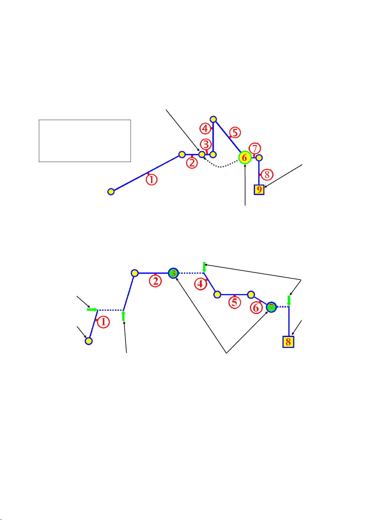
Loop back target segment
End
Loop Segment
Hold Start
Run
Continue
Triggers
End
Hold Stop
Hold Segments
Example:
Runs segments 1 to 5, then
repeats segments 3 to 5 for 500
times, before continuing on to
segments 7 to 9,
Loops Segments
A Loop Segment goes back to a specified segment in the current profile. This action is
repeated for the required number of times (1 to 9999) before the profile continues onwards.
More than one Loop Segment can be used in a profile, but they must not cross.
Figure 40. Loops Segments
Profile Running / Holding vs. Hold Segments
Figure 41. Run/Hold & Hold Segments
A Hold during a segment maintains the current setpoint value. Once the hold condition is
stopped the Ramp or Dwell continues. Depending on the configuration, a hold can be the
started & stopped by via a key-press, breaking the signal to a Run/Hold digital input, a serial
comms command or by the Auto-Hold feature (see below).
Note:
A running profile will also hold while Manual Control is selected.
A Hold Segment is a pre-planned hold, programmed into the profile. It maintains the value of
the previous segment. The profile does not continue until a Continue Trigger occurs. This
can be via a key-press, a digital input signal or after waiting for a time of day (available on
Recorder version only).
March 2012 Profiler Option Page 71
Page 71
The Auto-Hold Feature
Held if Auto-Hold set to Above Setpoint or Band
Dwell Segment
Setpoint
Hold Band
Process Variable
Held if Auto-Hold set to Below Setpoint or Band
Held if Auto-Hold set to Above Setpoint or Band
Process Variable
Ramp Setpoint
(without Auto-
Hold)
Hold Band
Ramp Setpoint
(with Auto-Hold)
Held if Auto-Hold set to Below Setpoint or Band
Each profile segment has individual Auto-Hold settings. If utilised, these ensure that the
profile and the actual process remain synchronised. If the process does not closely match
the required setpoint by remaining within the defined Hold Band, the profile can be held until
it returns within bounds.
The user can choose to hold the profile if the process goes beyond the Hold Band Above
The Setpoint only, Below The Setpoint only or to Band (either side of the setpoint). When
Auto-Hold becomes active, the profile status is shown as “Held”.
Figure 42. Auto-Hold On A Dwell Segment
During a Dwell, the dwell time is increase by the time that the process is outside of the hold
band in the selected direction(s). This ensures the process was at the desired level for the
required amount of time.
Figure 43. Auto-Hold On A Ramp Segment
During a Ramp segment, the ramp is held at the current setpoint value while the process is
outside of the hold band in the selected direction(s). The time taken to complete the ramp is
increased by the time taken by the Auto-Hold.
Page 72 Profiler Option March 2012
Page 72
PROFILE 4
PROFILE 31
PROFILE 7
Join (Profile 4 to Profile 31)
Join (Profile 31 to Profile 7)
Example:
Runs profile 4 once,
profile 31 three times
& profile 7 once.
This sequence is
repeated ten times.
Profile 31
Cycles = 3
Repeat Sequence = 10
Repeat Then End
(times to repeat = 10)
Profile 4
Cycles = 1
Profile 7
Cycles = 1
Profile Cycles & Repeat Sequences
A profile can be configured to run itself 1 to 9999 times or continuously using the Profile
Cycles setting. A profile ending with Repeat Then End will run the entire sequence of
profiles again from 1 to 9999 times before ending.
Figure 44. Profile Cycles & Repeats
Power/Signal Lost Recovery Actions
If there is a power cut while a profile is running, the instrument will use the defined Profile
Recovery Method once the power has been restored.
If there is a break in the input while a program is running, the unit will go to the Pre-Set
Power Value during the break condition. Once the condition has ended it carries out the
same recovery action as specified for power failure.
Note:
Recorder versions always use option E (Continue profile from the point it had reached
when the power failed) if the Power Off Time is less than the Profile Recovery Time
setting. If the power is off for more than this time, the defined Profile Recovery Method is
used.
March 2012 Profiler Option Page 73
Page 73

Possible Recovery Methods:
A Abort the profile and maintain the profile value from the time the power failed.
B Abort the profile and use Controller Setpoint value.
C Abort the profile with the Control outputs off.
D Restart the profile again from the beginning.
E Continue profile from the point it had reached when the power failed
Possible Profile End Actions:
A At profile end, maintain the Final Setpoint value of the last segment.
B At profile end, exit Profiler Mode and use the Controller Setpoint value.
C At profile end, remain in Profiler Mode with the Control outputs off.
Controller SP
Run
(Start-on SP)
Power Off
Power On
= Control Off
Planned Profile
Power Off Time
Controller SP
Run
(Start-on SP)
Normal Profile End
= Control Off
Last Profile SP
Controller SP
Figure 45. End, Abort and Recovery Actions
Profile End Actions
Once a running profile ends, that profiles’ Segment End Type defines action taken by the
instrument. If a sequence of profiles has been completed, the End Segment Type of the last
profile will be carried out. The possible end actions are explained below.
Figure 46. Profile End Action
Page 74 Profiler Option March 2012
Page 74

Possible Profile Abort Actions:
A Abort the profile and maintain the value of the setpoint at the time of the abort.
B Abort the profile and exit Profiler Mode using the Controller Setpoint value.
C Abort the profile and remain in Profiler Mode with the Control outputs off.
Controller SP
Run
(Start-on SP)
Profile Aborted
= Control Off
Last Profile SP
Controller SP
Profile Abort Actions
If a running profile is forced to end early, the Profile Abort Action defines action taken by
the instrument. This is set in the General Profile Configuration section of the Profile Setup
Menu, and is common to all profiles.
The possible options are explained below.
Figure 47. Profile Abort Action
March 2012 Profiler Option Page 75
Page 75
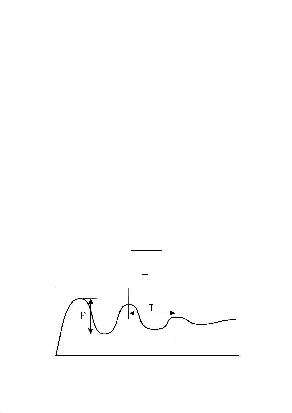
P
Input Span
T
6
11 Manually Tuning Controllers
Time
Process Variable
Single Control Tuning (PID with Primary Output only)
This technique balances the need to reach setpoint quickly, with the wish to limit setpoint
overshoot at start-up or during process changes. It determines values for the Primary
Proportional Band and the Integral and Derivative time constants that allow the PID control
algorithm to give acceptable results in most applications that use a single control device.
CAUTION:
This technique is suitable only for processes that are not harmed by large
fluctuations in the process variable.
1. Check that the Setpoint Upper Limit and Setpoint Lower Limit are set to safe levels for
your process. Adjust if required.
2. Set the Setpoint to the normal operating value for the process (or to a lower value if
overshoots beyond this value might cause damage).
3. Select On-Off control (i.e. set the Primary Proportional Band to zero).
4. Switch on the process. The process variable will oscillate about the setpoint. Record the
Peak-to-Peak variation (P) of the first cycle (i.e. the difference between the highest value
of the first overshoot and the lowest value of the first undershoot), and the time period of
the oscillation (T) in minutes. See the example diagram below - Manually Tuning PID.
5. Calculate the PID control parameters using the formula below. P.Pb is the Primary
Proportional Band, Int.T is the Integral Time Constant, and Der.T is the Derivative Time
Constant. The Input Span is the difference between Scale Range Lower Limit and Scale
Range Upper Limit:
P.Pb = x 100
Int.T = T minutes
Der.T = minutes
Page 76 Manual Tuning March 2012
Figure 48. Manually Tuning PID
Page 76

Dual Control Tuning (PID with Primary and Secondary Outputs)
This tuning technique balances the need to reach setpoint quickly, with the wish to limit
setpoint overshoot at start-up and during process changes. It determines values for the
Primary Proportional Band, Secondary Proportional Band, Integral and Derivative time
constants that allow the PID control algorithm to give acceptable results in most applications
that use dual control (e.g. Heat & Cool).
CAUTION:
This technique is suitable only for processes that are not harmed by large
fluctuations in the process variable.
1. Tune the controller using only the Primary Control output as described in the Single
Control Tuning section above.
2. Set the Secondary Proportional Band to the same value as the Primary Proportional Band
and monitor the operation of the controller in dual control mode. If there is a tendency to
oscillate as the control passes into the Secondary Proportional Band, increase its value. If
the process appears to be over-damped (slow to respond) in the region of the Secondary
Proportional Band, decrease its value.
3. When the PID tuning values have been determined, if there is a disturbance to the
process variable as control passes from one proportional band to the other, set the
Overlap/Deadband parameter to a positive value to introduce some overlap. Adjust this
value by trial and error until satisfactory results are obtained.
PI Tuning (Valve, Damper & Speed Controllers)
This tuning technique is used when controlling a damper, a modulating valve or motor speed
controller. It determines values for the Primary Proportional Band, and Integral Time
Constant. The Derivative Time Constant is normally set to OFF. This type of control (known
as PI Control) minimises valve/motor wear whilst giving optimal process control.
CAUTION:
This technique is suitable only for processes that are not harmed by large
fluctuations in the process variable.
1. Set the setpoint to the normal operating process value (or to a lower value if overshoot
beyond this value is likely to cause damage).
2. Set controller to On/Off Control mode (i.e. set Primary Proportional Band to the minimum
value).
3. Set the Integral Time Constant to OFF.
4. Set the Derivative Time Constant to OFF.
March 2012 Manual Tuning Page 77
Page 77
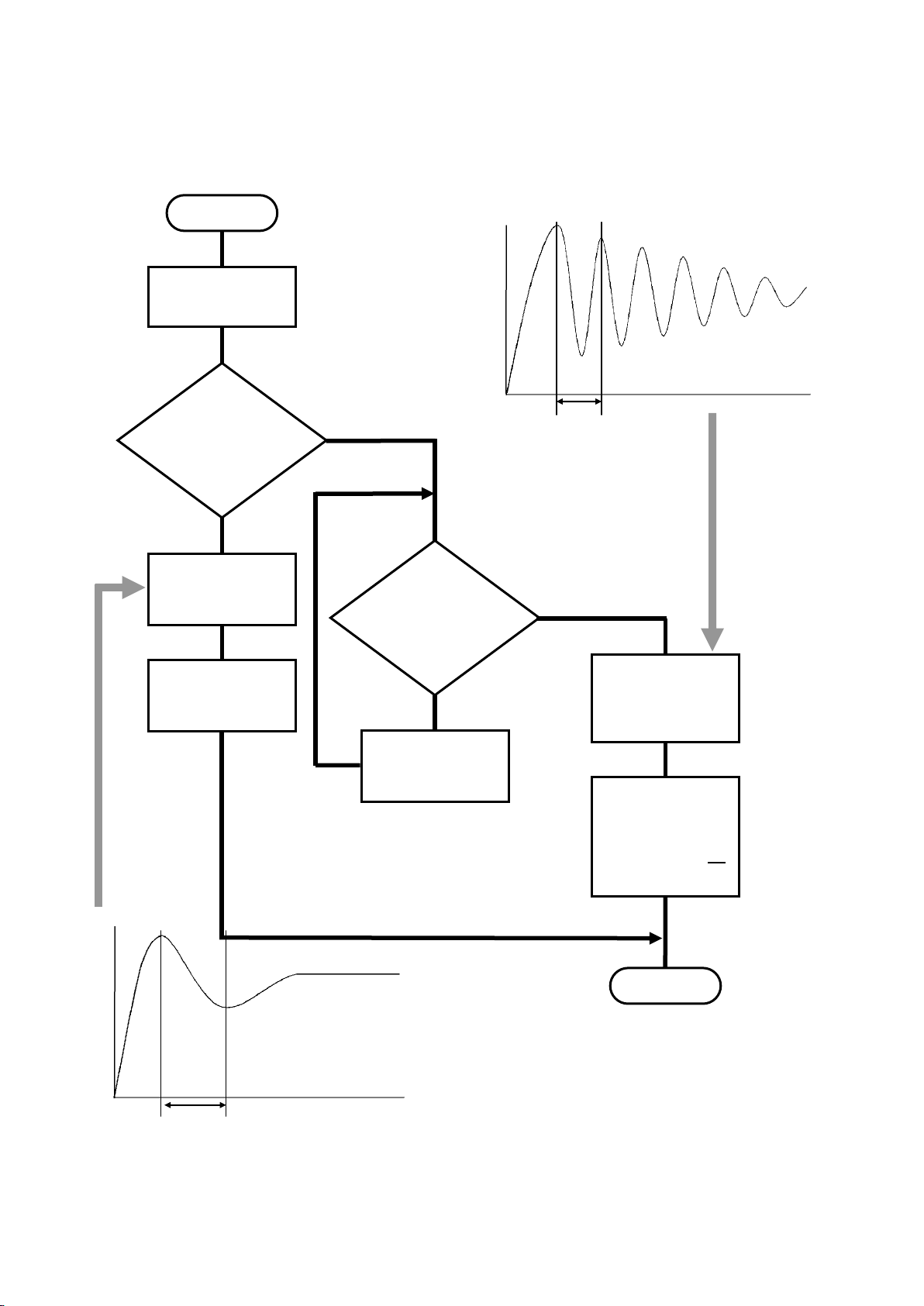
5. Follow the instructions in the diagram below. At each stage, allow sufficient settling time
The controller is now tuned.
Fine-tuning may be required
to optimise the controllers
Time
Process Variable
Tb
Time
Process Variable
Ta
START
Apply Power to
the load.
Does the
PV
continuously
Oscillate?
Note the time
interval Ta
Set P.Pb = 0.8%
Set Int.T = Ta
Are the
Oscillations
decaying to
zero?
Multiply P.Pb
setting by 1.5
END
Note the period
of the decaying
oscillations (T
b
)
Multiply P.Pb
setting by 1.5
Set Int.T = T
b
2
No
Yes
Yes
No
before moving on to the next stage. P.Pb is the Primary Proportional Band, Int.T is the
Integral Time Constant.
Page 78 Manual Tuning March 2012
Table 26. Manually Tuning Valve Control
Page 78

Fine Tuning.
A separate cycle time adjustment parameter is provided for the Primary and Secondary
control when using time proportioning control outputs.
Note:
Adjusting the cycle time affects the controllers operation; a shorter cycle time gives control
that is more accurate, but mechanical components such as relays will have a reduced life
span.
1. Increase the width of the proportional band if the process overshoots or oscillates
excessively.
2. Decrease the width of the proportional band if the process responds slowly or fails to
reach setpoint.
3. To find the optimum value for the Integral Time, decrease its value until the process
becomes unstable, then increase it a little at a time, until stability has is restored. Induce a
load disturbance or make a setpoint change to verify that the process stabilises. If not
increase the value some more and re-test.
Note:
Allow enough time for the controller and process to adjust between changes.
4. Initially add Derivative at a value between 1/4th and 1/10th of the Integral Time value.
5. Increase the Derivative Time if the process overshoots/undershoots, increase its value a
little at a time, if the process becomes unstable, until the oscillation stops. Induce a load
disturbance or make a setpoint change to verify that the process stabilises. If not decrease
the value some more and re-test.
Note:
When controlling a modulating valve, it is recommended that Derivative is set to OFF to
avoid excessive valve activity. Derivative can cause process instability in these processes.
6. After making all other adjustments, if an offset exists between the setpoint and the process
variable use the Bias (manual reset) to eliminate the error:
Below setpoint - use a larger value
Above setpoint - use a smaller value.
March 2012 Manual Tuning Page 79
Page 79

12 Serial Communications
Supported Protocols
Communication with a Modbus RTU or Modbus TCP master device is possible if the
appropriate communications module is fitted into Option Slot A. An RS485 Module is
required for Modbus RTU. An Ethernet Module is required for Modbus TCP.
The instrument can also act as Setpoint Master over RS485 in multi-zone applications. In this
mode the unit continuously sends it’s setpoint value using Modbus broadcast messages.
For a complete description of the Modbus protocol refer to the description provided at
http://www.modbus.org/
All models also have a configuration socket for use with the PC configuration software. An
RS232 to TTL lead (available from your supplier) is required in order to use this socket.
A front mounted USB port is available on some models; this can also be used to configure
the instrument or to transfer recorder or profile files via a USB memory stick.
RS485 Configuration
The RS485 address, bit rate and character format are configured via the front panel from the
Comms Configuration menu or by using the PC Configurator software.
Physical layer configuration settings possible are:
Data rate: 4800, 9600, 19200, 38400, 57600 or 115200 bps
Parity: None (default), Even, Odd
Character format: Always 8 bits per character.
Device Address: See below.
RS485 Device Addressing
The instrument must be assigned a unique device address in the range 1 to 255. This
address is used to recognise Modbus Queries intended for this instrument. With the
exception of globally addressed broadcast messages, the instrument ignores Modbus
Queries that do not match the address that has been assigned to it.
The instrument will accept broadcast messages (global queries) using device address 0 no
matter what device address is assigned. No response messages are returned for globally
addressed Queries.
Ethernet Configuration
For Modbus TCP communications (Modbus over Ethernet), the IP address can either be
assigned by a Dynamic Host Configuration Protocol (DHCP), BootP or AutoIP server on the
network, or manually assigned using the IP address allocation software tool.
Refer to the PC Software section of this manual for more information setting IP addresses.
The supported data rates 10/100BASE-T (10 or 100 Mbps) are automatically detected.
Page 80 Serial Communications March 2012
Page 80
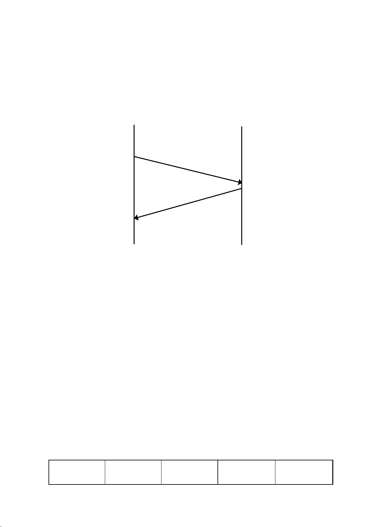
Inter-message
gap
Address
1 character
Function
1 character
Data
n characters
CRC Check
2 characters
MODBUS
MASTER
SLAVE
INSTRUMENT
QUERY
RESPONSE
Link Layer
A Query (or command) is transmitted from the Modbus Master to the Modbus Slave. The
slave instrument assembles the reply to the master. All of the instruments covered by this
manual are slave devices, and cannot act as a Modbus Master.
Figure 49. Modbus Link Layer
A message for either a QUERY or RESPONSE is made up of an inter-message gap followed
by a sequence of data characters. The inter-message gap is at least 3.5 data character times
- the transmitter must not start transmission until 3 character times have elapsed since
reception of the last character in a message, and must release the transmission line within 3
character times of the last character in a message.
Note:
Three character times is approximately 0.25ms at 115200 bps, 0.51ms at 57600 bps,
0.75ms at 38400 bps, 1.5ms at 19200 bps, 3ms at 9600 bps and 6ms at 4800bps.
Data is encoded for each character as binary data, transmitted LSB first.
For a QUERY the address field contains the address of the slave destination. The slave
address is given together with the Function and Data fields by the Application layer. The
CRC is generated from the given address, function and data characters.
For a RESPONSE the address field contains the address of the responding slave. The
Function and Data fields are generated by the slave application. The CRC is generated from
the address, function and data characters.
The standard MODBUS RTU CRC-16 calculation employing the polynomial 216+215+22+1 is
used.
March 2012 Serial Communications Page 81
Page 81
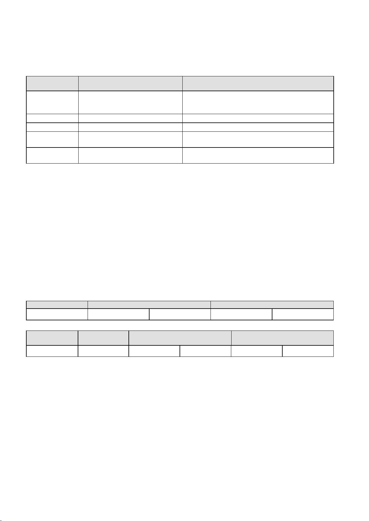
Supported Modbus Functions
Function Code
(decimal)
Modbus Meaning
Description
03 / 04
Read Holding/Input registers
Read current binary value of specified number of
parameters at given address. Up to 64 parameters
can be accessed with one Query.
06
Write Single Register
Writes two bytes to a specified word address.
08
Diagnostics
Used for loopback test only.
16 (0x10 hex)
Write Multiple Registers
Writes up to 253 bytes of data to the specified
address range.
23 (0x17 hex)
Read/Write Multiple Registers
Reads and Writes 253 bytes of data to the specified
address ranges.
QUERY
Function
Address of 1st Word
Number of Words
03 / 04
HI
LO
HI
LO
RESPONSE
Function
Number of
Bytes
First Word
Last Word
03 / 04
HI
LO
HI
LO
Modbus defines several function types. The following types are supported by this instrument:
Function Descriptions
The following is interpreted from the Modbus Protocol Description obtainable from
http://www.modbus.org/. Refer to that document if clarification is required.
In the function descriptions below, the preceding device address value is assumed, as is the
correctly formed two-byte CRC value at the end of the QUERY and RESPONSE frames.
Function 03 / 04 - Read Holding/Input Registers
Reads current binary value of data at the specified word addresses.
In the response the “Number of Bytes” indicates the number of data bytes read from the
instrument. E.g. if 5 words are read, the count will be 10 (A hex). The maximum number of
words that can be read is 64. If a parameter does not exist at one of the addresses read,
then a value of 0000h is returned for that word.
Page 82 Serial Communications March 2012
Page 82
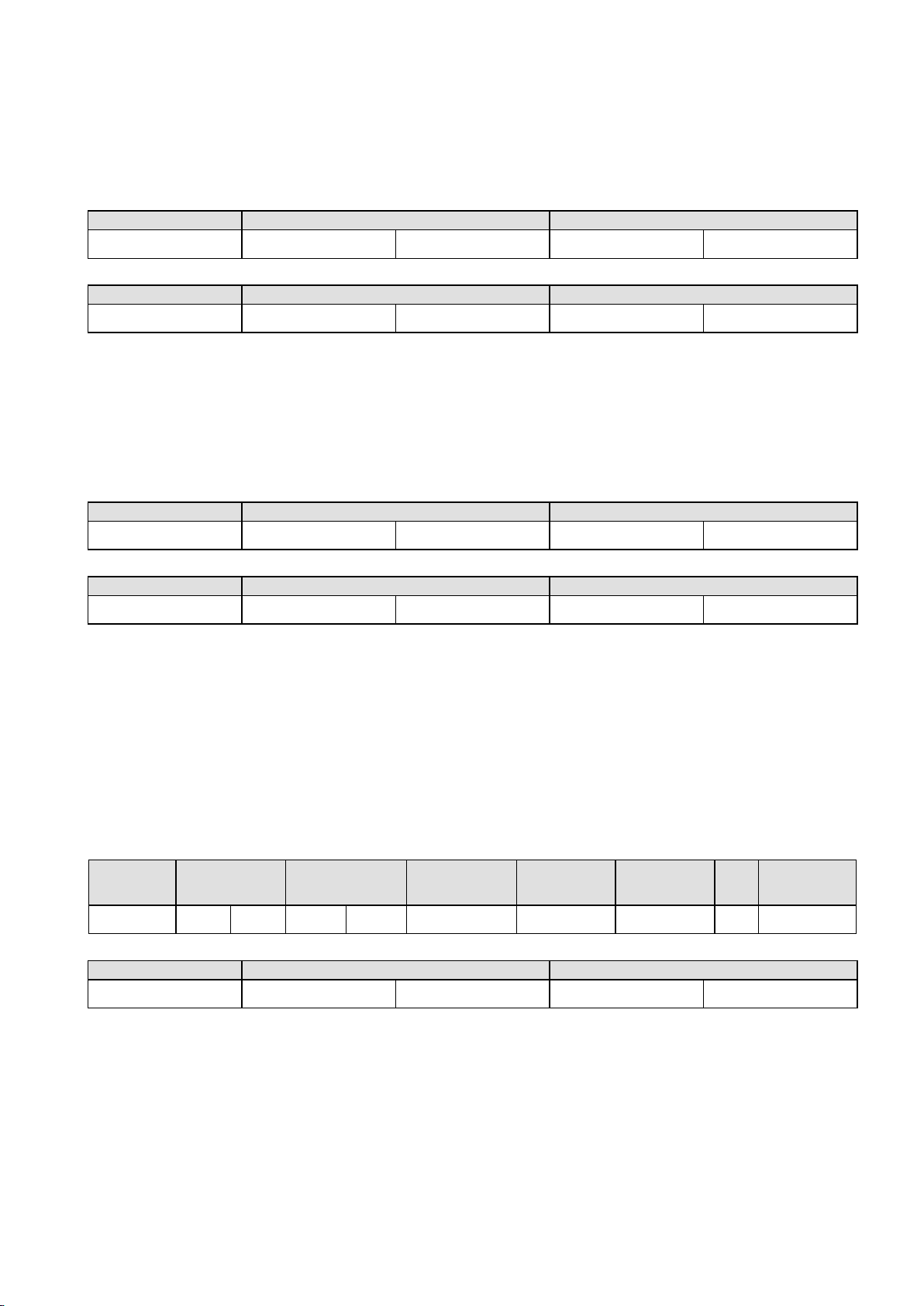
QUERY
Function
Address of Word
Value to write
06
HI
LO
HI
LO
RESPONSE
Function
Address of Word
Value written
06
HI
LO
HI
LO
QUERY
Function
Diagnostic Code
Value
08
HI =00
LO=00
HI
LO
RESPONSE
Function
Sub-function
Value
08
HI=00
LO=00
HI
LO
QUERY
Function
1st Write
Address
Number of
Words to Write
Number of
Query Bytes
1st Query
Byte
2nd Query
Byte
etc
Last Query
Byte
10
HI
LO
HI
LO
→
RESPONSE
Function
1st Word Address
Number of Words
10
HI
LO
HI
LO
Function 06 - Write Single Register
Writes two bytes to a specified word address.
Note:
The Response normally returns the same data as the Query.
Function 08 - Loopback Diagnostic Test
Note:
The Response normally returns the same data as the loopback Query. Other Diagnostic
Codes are not supported.
Function 16 - Write Multiple Registers (0x10 Hex)
Writes consecutive word (two-byte) values starting at the specified address.
Note:
March 2012 Serial Communications Page 83
The number of data bytes that can be written in one message is 253 bytes.
Page 83
Function 23 Hex - Read / Write Multiple Registers (0x17 hex)
QUERY
Function
1st Read
Address
Number of
Words to
Read
1st Write
Address
Number of
Words to
Write
Values to Write
1st Word
2nd Word
etc
Last Word
17
HI
LO
HI
LO
HI
LO
HI
LO
HI
LO
HI
LO → HI
LO
RESPONSE
Function
Number of
Bytes
Read Data
1st Word
2nd Word
etc
Last Word
17
HI
LO
HI
LO → HI
LO
Exception Code
Error Condition
Interpretation
00
Unused
None.
01
Illegal function
Function number out of range.
02
Illegal Data Address
Write functions: Parameter number out of range or not
supported. (for write functions only).
Read Functions: Start parameter does not exist or end
parameter greater than 65536.
03
Illegal Data Value
Attempt to write invalid data / required action not executed.
RESPONSE
Function
Exception Code
Original Function code with its Most
Significant Bit (MSB) set.
as detailed above
Reads and writes the requested number of consecutive words (two-bytes) starting at the
specified addresses.
Note:
The number of data bytes that can be read and written in one message is 253 bytes.
Exception Responses
When a QUERY is sent that the instrument cannot interpret, an Exception RESPONSE is
returned. Possible exception responses are:
The format of an exception response is:
Note:
In the case of multiple exception codes for a single QUERY the Exception code returned is
the one corresponding to the first parameter in error.
Page 84 Serial Communications March 2012
Page 84
Calculating Parameter Register Addresses
Integer Only
Integer+1
Floating Point
Register Address Calculation
(hex)
Address
Address + 0x4000
Address x 2 + 0x8000
(dec)
Address
Address + 16384
Address x 2 + 32768
Address Example:
(For Process Variable)
(hex)
0x0407
0x4407
0x880E
(dec)
1031
17415
34830
Data Value Returned:
If actual Value = 23.9 decimal
(hex)
0x00, 0x17
0x00, 0xEF
0x41, 0xBF, 0x33, 0x33
(dec)
23
239
23.9 as floating decimal
Address Example:
(For Selected Setpoint)
(hex)
0x101F
0x501F
0xA03E
(dec)
4127
20511
41022
Data Value Returned:
If Value = 1 (Alternative SP)
(hex)
0x00, 0x01
0x00, 0x0A
0x3F, 0x80, 0x00, 0x00
(dec) 1 10
1.0
as floating decimal
13 Modbus Parameters
The Modbus parameter register addresses are detailed in the tables below.
The Access column indicates if a parameter is read only (RO) or if it can also be written to
(R/W). Communications writes will not be implemented if the Writing Via Serial Comms
parameter in the Communications Configuration menu is set to Disabled.
Note:
Some parameters that do not apply for a particular configuration will accept reads and
writes (e.g. attempting to scale a Linear output which has not been fitted). Read only
parameters will return an exception if an attempt is made to write values to them.
Data Formats
Data can be read or written in three formats: Integer Only, Integer with 1 Decimal Place and
Floating Point Number.
The Modbus Address column shows the register address for each parameter in integer
format. Other formats can be calculated from the Integer Only address.
When working in Hexadecimal, the format calculations are:
Address for Integer with 1 Decimal Place = Integer address plus 0x4000
Address for Floating Point = Integer address multiplied by 2, plus 0x8000
When working in Decimal, the format calculations are:
Address for Integer with 1 Decimal Place = Integer address plus 16384
Address for Floating Point = Integer address multiplied by 2, plus 32768
Example Register Address Calculations
March 2012 Modbus Parameters Page 85
Page 85
Universal Process Input Parameters
Parameter Name
Modbus Address
Access
Values
(Dec)
(Hex)
Universal Process
Input Type
1024
0x0400
R/W
Value
Process Input Type
0
B Type Thermocouple
2
C Type Thermocouple
4
D Type Thermocouple
6
E Type Thermocouple
8
J Type Thermocouple
10
K Type Thermocouple
12
L Type Thermocouple
14
N Type Thermocouple
16
R Type Thermocouple
18
S Type Thermocouple
20
T Type Thermocouple
22
PtRh 20%: 40% Thermocouple
24
PT100 RTD
26
NI120 RTD
28
0 to 20mA DC
29
4 to 20mA DC
30
0 to 50mV DC
31
10 to 50mV DC
32
0 to 5V DC
33
1 to 5V DC
34
0 to 10V DC
35
2 to 10V DC
Engineering Units
1025
0x0401
R/W
Value
Engineering Units
0
= None
1
= °C (Default for Europe)
2
= °F (Default for USA)
Maximum Display
Decimal Places
1026
0x0402
R/W
Value
Decimal Places
0
None (e.g. 1234)
1
One (e.g. 123.4)
2
Two (e.g. 12.34)
3
Three (e.g. 1.234)
Range Minimum
1027
0x0403
R/W
Valid between input range maximum and minimum
(see Specifications Section for input details)
Range Maximum
1028
0x0404
R/W
Process Variable
Offset
1029
0x0405
R/W
Valid between scale range maximum and minimum
Filter Time Constant
1030
0x0406
R/W
Valid between 0.0 and 512.0
Process Variable
1031
0x0407
RO
The current process input value
Input Signal /Sensor
Break Flag
1032
0x0408
RO
Value
Process Input Break Status
0
Inactive
1
Active
Page 86 Modbus Parameters March 2012
Page 86
Parameter Name
Modbus Address
Access
Values
(Dec)
(Hex)
Input Signal Under
Range Flag
1033
0x0409
RO
Value
Process Input Under Range Status
0
Inactive
1
Active
Input Signal Over
Range Flag
1034
0x040A
RO
Value
Process Input Over Range Status
0
Inactive
1
Active
Cold Junction
Compensation
Enable/disable
1035
0x040B
R/W
Value
CJC Status
0
Disabled
1
Enabled (default)
Calibration Reminder
Enable
1048
0x0418
R/W
Value
Calibration Reminder Status
0
Disabled
1
Enabled
Calibration Reminder
Date
1049
0x0419
R/W
Data Format = ddmmyy where dd = day, mm = month
and yy = year (e.g. 200308 is 20th March 2008)
Calibration Reminder
Status
1052
0x041C
RO
Value
Calibration Status
0
Calibration OK
1
Calibration Required
Multi-point Scaling
Enable
1053
0x041D
R/W
Value
Multi-point Scaling Status
0
Disabled
1
Enabled (only if the input type is linear)
Scale Point 1
1054
0x041E
R/W
0.1 to 100.0%
Display Point 1
1055
0x041F
R/W
Valid between scale range maximum and minimum
Scale Point 2
1056
0x0420
R/W
>Scale point 1 to 100.0%
Display Point 2
1057
0x0421
R/W
Valid between scale range maximum and minimum
Scale Point 3
1058
0x0422
R/W
>Scale point 2 to 100.0%
Display Point 3
1059
0x0423
R/W
Valid between scale range maximum and minimum
Scale Point 4
1060
0x0424
R/W
>Scale point 3 to 100.0%
Display Point 4
1061
0x0425
R/W
Valid between scale range maximum and minimum
Scale Point 5
1062
0x0426
R/W
>Scale point 4 to 100.0%
Display Point 5
1063
0x0427
R/W
Valid between scale range maximum and minimum
Scale Point 6
1064
0x0428
R/W
>Scale point 5 to 100.0%
Display Point 6
1065
0x0429
R/W
Valid between scale range maximum and minimum
Scale Point 7
1066
0x042A
R/W
>Scale point 6 to 100.0%
Display Point 7
1067
0x042B
R/W
Valid between scale range maximum and minimum
Scale Point 8
1068
0x042C
R/W
>Scale point 7 to 100.0%
Display Point 8
1069
0x042D
R/W
Valid between scale range maximum and minimum
Scale Point 9
1070
0x042E
R/W
>Scale point 8 to 100.0%
Display Point 9
1071
0x042F
R/W
Valid between scale range maximum and minimum
Scale Point 10
1072
0x0430
R/W
>Scale point 9 to 100.0%
Display Point 10
1073
0x0431
R/W
Valid between scale range maximum and minimum
Scale Point 11
1074
0x0432
R/W
>Scale point 10 to 100.0%
Display Point 11
1075
0x0433
R/W
Valid between scale range maximum and minimum
Scale Point 12
1076
0x0434
R/W
>Scale point 11 to 100.0%
Display Point 12
1077
0x0435
R/W
Valid between scale range maximum and minimum
March 2012 Modbus Parameters Page 87
Page 87
Parameter Name
Modbus Address
Access
Values
(Dec)
(Hex)
Scale Point 13
1078
0x0436
R/W
>Scale point 12 to 100.0%
Display Point 13
1079
0x0437
R/W
Valid between scale range maximum and minimum
Scale Point 14
1080
0x0438
R/W
>Scale point 13 to 100.0%
Display Point 14
1081
0x0439
R/W
Valid between scale range maximum and minimum
Scale Point 15
1082
0x043A
R/W
>Scale point 14 to 100.0%
Display Point 15
1083
0x043B
R/W
Valid between scale range maximum and minimum
Parameter Name
Modbus Address
Access
Values
(Dec)
(Hex)
Digital Input A Status
2115
0x0845
RO
Value
Digital Input A Status
0
Inactive
1
Active
Option Slot A
Module Type
2116
0x0844
RO
Value
Module Fitted In Slot A
0
None Fitted
1
RS485 Communications
3
Digital Input
4
Auxiliary Input A
5
Ethernet Communications
255
Error (unrecognised module)
RS485 Address
2117
0x0845
R/W
Value
RS485 Address
0
Modbus Master mode
1 to 255
Modbus Slave Address
RS485 Data Rate
2118
0x0846
R/W
Value
Baud Rate
0
4800
1
9600
2
19200 (Default)
3
38400
4
57600
5
115200
RS485 Parity
2119
0x0847
R/W
Value
Parity
0
None
1
Even
2
Odd
Auxiliary Input A
Type
2120
0x0848
R/W
Value
Auxiliary A Input Type
0
0 to 20mA DC
1
4 to 20mA DC
2
0 to 10V DC
3
2 to 10V DC
4
0 to 5V DC
5
1 to 5V DC
Target Setpoint
Address
2121
0x0849
R/W
Target setpoint parameter address for master mode
Option Slot A Parameters
Page 88 Modbus Parameters March 2012
Page 88
Parameter Name
Modbus Address
Access
Values
(Dec)
(Hex)
Master Transmit
Format
2123
0x084B
R/W
Value
Data Format
0
Integer
1
Integer with 1 decimal place
2
Floating point number
Comms Write
Enable/Disable
2124
0x084C
R/W
Value
Communications Status
0
Writing via serial communications disabled
1
Writing via serial communications enabled
Auxiliary Input A
Input Signal Break
2127
0x084F
RO
Value
Auxiliary Input A Break Status
0
Inactive
1
Active
Auxiliary Input A
Input Signal Under
Range
2128
0x0850
RO
Value
Auxiliary Input A Under Range Status
0
Inactive
1
Active
Auxiliary Input A
Input Signal Over
Range
2129
0x0851
RO
Value
Auxiliary Input A Over Range Status
0
Inactive
1
Active
Parameter Name
Modbus Address
Access
Values
(Dec)
(Hex)
Auxiliary Input B
Type
2080
0x0820
R/W
Value
Auxiliary B Input Type
0
0 to 20mA DC
1
4 to 20mA DC
2
0 to 10V DC
3
2 to 10V DC
4
0 to 5V DC
5
1 to 5V DC
6
0 to 100mV DC
7
>2000 Ohm Potentiometer
Option Slot B
Module Type
2081
0x0821
RO
Value
Module Fitted In Slot B
0
None Fitted
1
Auxiliary Input B with Digital Input B
255
Error (unrecognised module)
Auxiliary Input B
Input Signal Break
2082
0x0822
RO
Value
Auxiliary Input B Break Status
0
Inactive
1
Active
Auxiliary Input B
Input Signal Under
Range
2083
0x0823
RO
Value
Auxiliary Input B Under Range Status
0
Inactive
1
Active
Auxiliary Input B
Input Signal Over
Range
2084
0x0824
RO
Value
Auxiliary Input B Over Range Status
0
Inactive
1
Active
Option Slot B Parameters
March 2012 Modbus Parameters Page 89
Page 89
Parameter Name
Modbus Address
Access
Values
(Dec)
(Hex)
Digital Input B Status
2085
0x0825
RO
Value
Digital Input B Status
0
Inactive
1
Active
Calibration Status
2086
0x0826
RO
Value
Calibration Status
0
Calibration OK
1
Calibration Required
Parameter Name
Modbus Address
Access
Values
(Dec)
(Hex)
Option Slot 1
Module Type
2130
0x0852
RO
Value
Module Fitted In Slot 1
0
None Fitted
1
Single Relay
2
Single SSR Driver
3
Linear mA/V DC
8
Triac
255
Error (unrecognised module)
Linear mA/V DC
Output 1 Type
2131
0x0853
R/W
Value
Linear Output 1 Type
0
0 to 5V DC
1
0 to 10V DC
2
2 to 10V DC
3
0 to 20mA DC
4
4 to 20mA DC
5
Variable 0 to 10VDC Transmitter PSU
Digital Output 1
Status
2132
0x0854
RO
Value
Digital Output 1 Status
0
Inactive
1
Active
Linear Output 1
Level Status
2134
0x0856
RO
-2.0% to 102.0% of nominal range
(control output will over/under drive by 2%).
Linear Output 1
Function
2144
0x0860
R/W
Value
Linear Output 1 Function
0
Disabled
1
Primary Output Power
2
Secondary Output Power
3
Retransmit Actual Setpoint Value
4
Retransmit Process Variable Value
Digital Output 1
Function
(Relays, SSR
Drivers or Triacs.
Linear Outputs are
mA or VDC)
2146
0x0862
R/W
Value
Digital Output 1 Function
0
Disabled
1
Primary Output Power
2
Secondary Output Power
3
Alarm
4
Alarm and Event
Output 1 Alarm
Selection
2148
0x0864
R/W
Value
Output 1 Alarm Selection
0
Alarm 1. Direct Acting
Option Slot 1 Parameters
Page 90 Modbus Parameters March 2012
Page 90
Parameter Name
Modbus Address
Access
Values
(Dec)
(Hex)
1
Alarm 1. Reverse Acting
2
Alarm 2, Direct Acting
3
Alarm 2. Reverse Acting
4
Alarm 3. Direct Acting
5
Alarm 3. Reverse Acting
6
Alarm 4. Direct Acting
7
Alarm 4. Reverse Acting
8
Alarm 5. Direct Acting
9
Alarm 5. Reverse Acting
10
OR of Alarm 1 or 2. Direct
11
OR of Alarm 1 or 2. Reverse
12
OR of Alarm 1, 2, or 3. Direct
13
OR of Alarm 1, 2, or 3. Reverse
14
OR of Alarm 1, 2, 3, or 4. Direct
15
OR of Alarm 1, 2, 3, or 4. Reverse
16
OR of Alarm 1, 2, 3, 4 or 5. Direct
17
OR of Alarm 1, 2, 3, 4 or 5. Reverse
Output 1 Event And
Alarm Selection
2150
0x0866
R/W
Value
Output 1 Event And Alarm Selection
0
Event 1. Direct Acting
1
Event 1. Reverse Acting
2
Event 2. Direct Acting
3
Event 2. Reverse Acting
4
Event 3. Direct Acting
5
Event 3. Reverse Acting
6
Event 4. Direct Acting
7
Event 4. Reverse Acting
8
Event 5. Direct Acting
9
Event 5. Reverse Acting
10
Profile Running. Direct Acting
11
Profile Running. Reverse Acting
12
End of Profile. Direct Acting
13
End of Profile. Reverse Acting
14
Event 1 AND Alarm 1. Direct Acting
15
Event 1 AND Alarm 1. Reverse Acting
16
Event 2 AND Alarm 2. Direct Acting
17
Event 2 AND Alarm 2. Reverse Acting
18
Event 3 AND Alarm 3. Direct Acting
19
Event 3 AND Alarm 3. Reverse Acting
20
Event 4 AND Alarm 4. Direct Acting
21
Event 4 AND Alarm 4. Reverse Acting
22
Event 5 AND Alarm 5. Direct Acting
23
Event 5 AND Alarm 5. Reverse Acting
Output 1 Retransmit
Minimum
2152
0x0868
R/W
Limited by input range maximum and minimum
Output 1 Retransmit
Maximum
2153
0x0869
R/W
Limited by input range maximum and minimum
March 2012 Modbus Parameters Page 91
Page 91
Option Slot 2 Parameters
Parameter Name
Modbus Address
Access
Values
(Dec)
(Hex)
Option Slot 2
Module Type
2160
0x0870
RO
Value
Module Fitted In Slot 2
0
None Fitted
1
Single Relay
2
Single SSR Driver
3
Linear mA/V DC
8
Triac
9
Dual Relay
10
Dual SSR Driver
11
24VDC Transmitter PSU
255
Error (unrecognised module)
Linear mA/V DC
Output 2 Type
2161
0x0871
R/W
Value
Linear Output 2 Type
0
0 to 5V DC
1
0 to 10V DC
2
2 to 10V DC
3
0 to 20mA DC
4
4 to 20mA DC
5
Variable 0 to 10VDC Transmitter PSU
Digital Output 2 or
2A Status
2162
0x0872
RO
Value
Digital Output 2 or 2A Status
0
Inactive
1
Active
Digital Output 2B
Status
2163
0x0873
RO
Value
Digital Output 2B Status
0
Inactive
1
Active
Linear Output 2
Level Status
2164
0x0874
RO
-2.0% to 102.0% of nominal range
(control output will over/under drive by 2%).
Linear Output 2 or
2A Function
2174
0x087E
R/W
Value
Linear Output 2 or 2A Function
0
Disabled
1
Primary Output Power
2
Secondary Output Power
3
Retransmit Actual Setpoint Value
4
Retransmit Process Variable Value
Digital Output 2 or
2A Function
2176
0x0880
R/W
Value
Digital Output 2 or 2A Function
0
Disabled
1
Primary Output Power
2
Secondary Output Power
3
Alarm
4
Alarm and Event
Page 92 Modbus Parameters March 2012
Page 92
Parameter Name
Modbus Address
Access
Values
(Dec)
(Hex)
Digital Output 2B
Function
2177
0x0881
R/W
Value
Digital Output 2B Function
0
Disabled
1
Primary Output Power
2
Secondary Output Power
3
Alarm
4
Alarm and Event
Output 2 or 2A
Alarm Selection
2178
0x0882
R/W
Value
Output 2 or 2A Alarm Selection
0
Alarm 1. Direct Acting
1
Alarm 1. Reverse Acting
2
Alarm 2, Direct Acting
3
Alarm 2. Reverse Acting
4
Alarm 3. Direct Acting
5
Alarm 3. Reverse Acting
6
Alarm 4. Direct Acting
7
Alarm 4. Reverse Acting
8
Alarm 5. Direct Acting
9
Alarm 5. Reverse Acting
10
OR of Alarm 1 or 2. Direct
11
OR of Alarm 1 or 2. Reverse
12
OR of Alarm 1, 2, or 3. Direct
13
OR of Alarm 1, 2, or 3. Reverse
14
OR of Alarm 1, 2, 3, or 4. Direct
15
OR of Alarm 1, 2, 3, or 4. Reverse
16
OR of Alarm 1, 2, 3, 4 or 5. Direct
17
OR of Alarm 1, 2, 3, 4 or 5. Reverse
Output 2B Alarm
Selection
2179
0x0883
R/W
Value
Output 2B Alarm Selection
0
Alarm 1. Direct Acting
1
Alarm 1. Reverse Acting
2
Alarm 2, Direct Acting
3
Alarm 2. Reverse Acting
4
Alarm 3. Direct Acting
5
Alarm 3. Reverse Acting
6
Alarm 4. Direct Acting
7
Alarm 4. Reverse Acting
8
Alarm 5. Direct Acting
9
Alarm 5. Reverse Acting
10
OR of Alarm 1 or 2. Direct
11
OR of Alarm 1 or 2. Reverse
12
OR of Alarm 1, 2, or 3. Direct
13
OR of Alarm 1, 2, or 3. Reverse
14
OR of Alarm 1, 2, 3, or 4. Direct
15
OR of Alarm 1, 2, 3, or 4. Reverse
16
OR of Alarm 1, 2, 3, 4 or 5. Direct
17
OR of Alarm 1, 2, 3, 4 or 5. Reverse
March 2012 Modbus Parameters Page 93
Page 93
Parameter Name
Modbus Address
Access
Values
(Dec)
(Hex)
Output 2 or 2A
Event And Alarm
Selection
2180
0x0884
R/W
Value
Output 2 or 2A Event/Alarm Selection
0
Event 1. Direct Acting
1
Event 1. Reverse Acting
2
Event 2. Direct Acting
3
Event 2. Reverse Acting
4
Event 3. Direct Acting
5
Event 3. Reverse Acting
6
Event 4. Direct Acting
7
Event 4. Reverse Acting
8
Event 5. Direct Acting
9
Event 5. Reverse Acting
10
Profile Running. Direct Acting
11
Profile Running. Reverse Acting
12
End of Profile. Direct Acting
13
End of Profile. Reverse Acting
14
Event 1 AND Alarm 1. Direct Acting
15
Event 1 AND Alarm 1. Reverse Acting
16
Event 2 AND Alarm 2. Direct Acting
17
Event 2 AND Alarm 2. Reverse Acting
18
Event 3 AND Alarm 3. Direct Acting
19
Event 3 AND Alarm 3. Reverse Acting
20
Event 4 AND Alarm 4. Direct Acting
21
Event 4 AND Alarm 4. Reverse Acting
22
Event 5 AND Alarm 5. Direct Acting
23
Event 5 AND Alarm 5. Reverse Acting
Output 2B Event
And Alarm Selection
2181
0x0885
R/W
Value
Output 2B Event/Alarm Selection
0
Event 1. Direct Acting
1
Event 1. Reverse Acting
2
Event 2. Direct Acting
3
Event 2. Reverse Acting
4
Event 3. Direct Acting
5
Event 3. Reverse Acting
6
Event 4. Direct Acting
7
Event 4. Reverse Acting
8
Event 5. Direct Acting
9
Event 5. Reverse Acting
10
Profile Running. Direct Acting
11
Profile Running. Reverse Acting
12
End of Profile. Direct Acting
13
End of Profile. Reverse Acting
14
Event 1 AND Alarm 1. Direct Acting
15
Event 1 AND Alarm 1. Reverse Acting
16
Event 2 AND Alarm 2. Direct Acting
17
Event 2 AND Alarm 2. Reverse Acting
18
Event 3 AND Alarm 3. Direct Acting
19
Event 3 AND Alarm 3. Reverse Acting
Page 94 Modbus Parameters March 2012
Page 94
Parameter Name
Modbus Address
Access
Values
(Dec)
(Hex)
20
Event 4 AND Alarm 4. Direct Acting
21
Event 4 AND Alarm 4. Reverse Acting
22
Event 5 AND Alarm 5. Direct Acting
23
Event 5 AND Alarm 5. Reverse Acting
Output 2 Retransmit
Minimum
2182
0x0886
R/W
Limited by input range maximum/minimum
Output 2 Retransmit
Maximum
2183
0x0887
R/W
Limited by input range maximum/minimum
Parameter Name
Modbus Address
Access
Values
(Dec)
(Hex)
Option Slot 3
Module Type
2192
0x0890
RO
Value
Module Fitted In Slot 3
0
None Fitted
1
Single Relay
2
Single SSR Driver
3
Linear mA/V DC
8
Triac
9
Dual Relay
10
Dual SSR Driver
11
24VDC Transmitter PSU
255
Error (unrecognised module)
Linear mA/V DC
Output 3 Type
2193
0x0891
R/W
Value
Linear Output 3 Type
0
0 to 5V DC
1
0 to 10V DC
2
2 to 10V DC
3
0 to 20mA DC
4
4 to 20mA DC
5
Variable 0 to 10VDC Transmitter PSU
Digital Output 3 or
3A Status
2194
0x0892
RO
Value
Digital Output 3 or 3A Status
0
Inactive
1
Active
Digital Output 3B
Status
2195
0x0893
RO
Value
Digital Output 3B Status
0
Inactive
1
Active
Linear Output 3
Level Status
2196
0x0894
RO
-2.0% to 102.0% of nominal range
(control output will over/under drive by 2%).
Linear Output 3 or
3A Function
2203
0x089B
R/W
Value
Linear Output 3 or 3A Function
0
Disabled
1
Primary Output Power
2
Secondary Output Power
3
Retransmit Actual Setpoint Value
4
Retransmit Process Variable Value
Option Slot 3 Parameters
March 2012 Modbus Parameters Page 95
Page 95
Parameter Name
Modbus Address
Access
Values
(Dec)
(Hex)
Digital Output 3 or
3A Function
2205
0x089D
R/W
Value
Digital Output 3 or 3A Function
0
Disabled
1
Primary Output Power
2
Secondary Output Power
3
Alarm
4
Alarm and Event
Digital Output 3B
Function
2206
0x089E
R/W
Value
Digital Output 3B Function
0
Disabled
1
Primary Output Power
2
Secondary Output Power
3
Alarm
4
Alarm and Event
Output 3 or 3A
Alarm Selection
2207
0x089F
R/W
Value
Output 3 or 3A Alarm Selection
0
Alarm 1. Direct Acting
1
Alarm 1. Reverse Acting
2
Alarm 2, Direct Acting
3
Alarm 2. Reverse Acting
4
Alarm 3. Direct Acting
5
Alarm 3. Reverse Acting
6
Alarm 4. Direct Acting
7
Alarm 4. Reverse Acting
8
Alarm 5. Direct Acting
9
Alarm 5. Reverse Acting
10
OR of Alarm 1 or 2. Direct
11
OR of Alarm 1 or 2. Reverse
12
OR of Alarm 1, 2, or 3. Direct
13
OR of Alarm 1, 2, or 3. Reverse
14
OR of Alarm 1, 2, 3, or 4. Direct
15
OR of Alarm 1, 2, 3, or 4. Reverse
16
OR of Alarm 1, 2, 3, 4 or 5. Direct
17
OR of Alarm 1, 2, 3, 4 or 5. Reverse
Output 3B Alarm
Selection
2208
0x08A0
R/W
Value
Output 3B Alarm Selection
0
Alarm 1. Direct Acting
1
Alarm 1. Reverse Acting
2
Alarm 2, Direct Acting
3
Alarm 2. Reverse Acting
4
Alarm 3. Direct Acting
5
Alarm 3. Reverse Acting
6
Alarm 4. Direct Acting
7
Alarm 4. Reverse Acting
8
Alarm 5. Direct Acting
9
Alarm 5. Reverse Acting
10
OR of Alarm 1 or 2. Direct
11
OR of Alarm 1 or 2. Reverse
12
OR of Alarm 1, 2, or 3. Direct
Page 96 Modbus Parameters March 2012
Page 96
Parameter Name
Modbus Address
Access
Values
(Dec)
(Hex)
13
OR of Alarm 1, 2, or 3. Reverse
14
OR of Alarm 1, 2, 3, or 4. Direct
15
OR of Alarm 1, 2, 3, or 4. Reverse
16
OR of Alarm 1, 2, 3, 4 or 5. Direct
17
OR of Alarm 1, 2, 3, 4 or 5. Reverse
Output 3 or 3A
Event And Alarm
Selection
2209
0x08A1
R/W
Value
Output 3 or 3A Event/Alarm Selection
0
Event 1. Direct Acting
1
Event 1. Reverse Acting
2
Event 2. Direct Acting
3
Event 2. Reverse Acting
4
Event 3. Direct Acting
5
Event 3. Reverse Acting
6
Event 4. Direct Acting
7
Event 4. Reverse Acting
8
Event 5. Direct Acting
9
Event 5. Reverse Acting
10
Profile Running. Direct Acting
11
Profile Running. Reverse Acting
12
End of Profile. Direct Acting
13
End of Profile. Reverse Acting
14
Event 1 AND Alarm 1. Direct Acting
15
Event 1 AND Alarm 1. Reverse Acting
16
Event 2 AND Alarm 2. Direct Acting
17
Event 2 AND Alarm 2. Reverse Acting
18
Event 3 AND Alarm 3. Direct Acting
19
Event 3 AND Alarm 3. Reverse Acting
20
Event 4 AND Alarm 4. Direct Acting
21
Event 4 AND Alarm 4. Reverse Acting
22
Event 5 AND Alarm 5. Direct Acting
23
Event 5 AND Alarm 5. Reverse Acting
Output 3B Event
And Alarm Selection
2210
0x08A2
R/W
Value
Output 3B Event/Alarm Selection
0
Event 1. Direct Acting
1
Event 1. Reverse Acting
2
Event 2. Direct Acting
3
Event 2. Reverse Acting
4
Event 3. Direct Acting
5
Event 3. Reverse Acting
6
Event 4. Direct Acting
7
Event 4. Reverse Acting
8
Event 5. Direct Acting
9
Event 5. Reverse Acting
10
Profile Running. Direct Acting
11
Profile Running. Reverse Acting
12
End of Profile. Direct Acting
13
End of Profile. Reverse Acting
March 2012 Modbus Parameters Page 97
Page 97
Parameter Name
Modbus Address
Access
Values
(Dec)
(Hex)
14
Event 1 AND Alarm 1. Direct Acting
15
Event 1 AND Alarm 1. Reverse Acting
16
Event 2 AND Alarm 2. Direct Acting
17
Event 2 AND Alarm 2. Reverse Acting
18
Event 3 AND Alarm 3. Direct Acting
19
Event 3 AND Alarm 3. Reverse Acting
20
Event 4 AND Alarm 4. Direct Acting
21
Event 4 AND Alarm 4. Reverse Acting
22
Event 5 AND Alarm 5. Direct Acting
23
Event 5 AND Alarm 5. Reverse Acting
Output 3 Retransmit
Minimum
2211
0x08A3
R/W
Limited by input range maximum/minimum
Output 3 Retransmit
Maximum
2212
0x08A4
R/W
Limited by input range maximum/minimum
Parameter Name
Modbus Address
Access
Values
(Dec)
(Hex)
Option Slot 4
Module Type
2222
0x08AE
RO
Value
Module Fitted In Slot 4
0
None Fitted
1
Quad Relay
255
Error (unrecognised module)
Digital Output 4
Status
2223
0x08AF
RO
Value
Digital Output 4A, 4B, 4C & 4D Status
0
All outputs inactive
Bit 0
Output 4A Active
Bit 1
Output 4B Active
Bit 2
Output 4C Active
Bit 3
Output 4D Active
Digital Output 4A
Function
2230
0x08B6
R/W
Value
Digital Output 4A Function
0
Disabled
1
Primary Output Power
2
Secondary Output Power
3
Alarm
4
Alarm and Event
Digital Output 4B
Function
2231
0x08B7
R/W
Value
Digital Output 4B Function
0
Disabled
1
Primary Output Power
2
Secondary Output Power
3
Alarm
4
Alarm and Event
Option Slot 4 Parameters
Page 98 Modbus Parameters March 2012
Page 98
Parameter Name
Modbus Address
Access
Values
(Dec)
(Hex)
Digital Output 4C
Function
2232
0x08B8
R/W
Value
Digital Output 4C Function
0
Disabled
1
Primary Output Power
2
Secondary Output Power
3
Alarm
4
Alarm and Event
Digital Output 4D
Function
2233
0x08B9
R/W
Value
Digital Output 4D Function
0
Disabled
1
Primary Output Power
2
Secondary Output Power
3
Alarm
4
Alarm and Event
Output 4A Alarm
Selection
2234
0x08BA
R/W
Value
Output 4A Alarm Selection
0
Alarm 1. Direct Acting
1
Alarm 1. Reverse Acting
2
Alarm 2, Direct Acting
3
Alarm 2. Reverse Acting
4
Alarm 3. Direct Acting
5
Alarm 3. Reverse Acting
6
Alarm 4. Direct Acting
7
Alarm 4. Reverse Acting
8
Alarm 5. Direct Acting
9
Alarm 5. Reverse Acting
10
OR of Alarm 1 or 2. Direct
11
OR of Alarm 1 or 2. Reverse
12
OR of Alarm 1, 2, or 3. Direct
13
OR of Alarm 1, 2, or 3. Reverse
14
OR of Alarm 1, 2, 3, or 4. Direct
15
OR of Alarm 1, 2, 3, or 4. Reverse
16
OR of Alarm 1, 2, 3, 4 or 5. Direct
17
OR of Alarm 1, 2, 3, 4 or 5. Reverse
Output 4B Alarm
Selection
2235
0x08BB
R/W
Value
Output 4B Alarm Selection
0
Alarm 1. Direct Acting
1
Alarm 1. Reverse Acting
2
Alarm 2, Direct Acting
3
Alarm 2. Reverse Acting
4
Alarm 3. Direct Acting
5
Alarm 3. Reverse Acting
6
Alarm 4. Direct Acting
7
Alarm 4. Reverse Acting
8
Alarm 5. Direct Acting
9
Alarm 5. Reverse Acting
10
OR of Alarm 1 or 2. Direct
11
OR of Alarm 1 or 2. Reverse
12
OR of Alarm 1, 2, or 3. Direct
March 2012 Modbus Parameters Page 99
Page 99

Parameter Name
Modbus Address
Access
Values
(Dec)
(Hex)
13
OR of Alarm 1, 2, or 3. Reverse
14
OR of Alarm 1, 2, 3, or 4. Direct
15
OR of Alarm 1, 2, 3, or 4. Reverse
16
OR of Alarm 1, 2, 3, 4 or 5. Direct
17
OR of Alarm 1, 2, 3, 4 or 5. Reverse
Output 4C Alarm
Selection
2236
0x08BC
R/W
Value
Output 4C Alarm Selection
0
Alarm 1. Direct Acting
1
Alarm 1. Reverse Acting
2
Alarm 2, Direct Acting
3
Alarm 2. Reverse Acting
4
Alarm 3. Direct Acting
5
Alarm 3. Reverse Acting
6
Alarm 4. Direct Acting
7
Alarm 4. Reverse Acting
8
Alarm 5. Direct Acting
9
Alarm 5. Reverse Acting
10
OR of Alarm 1 or 2. Direct
11
OR of Alarm 1 or 2. Reverse
12
OR of Alarm 1, 2, or 3. Direct
13
OR of Alarm 1, 2, or 3. Reverse
14
OR of Alarm 1, 2, 3, or 4. Direct
15
OR of Alarm 1, 2, 3, or 4. Reverse
16
OR of Alarm 1, 2, 3, 4 or 5. Direct
17
OR of Alarm 1, 2, 3, 4 or 5. Reverse
Output 4D Alarm
Selection
2237
0x08BD
R/W
Value
Output 4D Alarm Selection
0
Alarm 1. Direct Acting
1
Alarm 1. Reverse Acting
2
Alarm 2, Direct Acting
3
Alarm 2. Reverse Acting
4
Alarm 3. Direct Acting
5
Alarm 3. Reverse Acting
6
Alarm 4. Direct Acting
7
Alarm 4. Reverse Acting
8
Alarm 5. Direct Acting
9
Alarm 5. Reverse Acting
10
OR of Alarm 1 or 2. Direct
11
OR of Alarm 1 or 2. Reverse
12
OR of Alarm 1, 2, or 3. Direct
13
OR of Alarm 1, 2, or 3. Reverse
14
OR of Alarm 1, 2, 3, or 4. Direct
15
OR of Alarm 1, 2, 3, or 4. Reverse
16
OR of Alarm 1, 2, 3, 4 or 5. Direct
17
OR of Alarm 1, 2, 3, 4 or 5. Reverse
Page 100 Modbus Parameters March 2012
Page 100
Parameter Name
Modbus Address
Access
Values
(Dec)
(Hex)
Output 4A Event
And Alarm Selection
2238
0x08BE
R/W
Value
Output 4A Event/Alarm Selection
0
Event 1. Direct Acting
1
Event 1. Reverse Acting
2
Event 2. Direct Acting
3
Event 2. Reverse Acting
4
Event 3. Direct Acting
5
Event 3. Reverse Acting
6
Event 4. Direct Acting
7
Event 4. Reverse Acting
8
Event 5. Direct Acting
9
Event 5. Reverse Acting
10
Profile Running. Direct Acting
11
Profile Running. Reverse Acting
12
End of Profile. Direct Acting
13
End of Profile. Reverse Acting
14
Event 1 AND Alarm 1. Direct Acting
15
Event 1 AND Alarm 1. Reverse Acting
16
Event 2 AND Alarm 2. Direct Acting
17
Event 2 AND Alarm 2. Reverse Acting
18
Event 3 AND Alarm 3. Direct Acting
19
Event 3 AND Alarm 3. Reverse Acting
20
Event 4 AND Alarm 4. Direct Acting
21
Event 4 AND Alarm 4. Reverse Acting
22
Event 5 AND Alarm 5. Direct Acting
23
Event 5 AND Alarm 5. Reverse Acting
Output 4B Event
And Alarm Selection
2239
0x08BF
R/W
Value
Output 4B Event/Alarm Selection
0
Event 1. Direct Acting
1
Event 1. Reverse Acting
2
Event 2. Direct Acting
3
Event 2. Reverse Acting
4
Event 3. Direct Acting
5
Event 3. Reverse Acting
6
Event 4. Direct Acting
7
Event 4. Reverse Acting
8
Event 5. Direct Acting
9
Event 5. Reverse Acting
10
Profile Running. Direct Acting
11
Profile Running. Reverse Acting
12
End of Profile. Direct Acting
13
End of Profile. Reverse Acting
14
Event 1 AND Alarm 1. Direct Acting
15
Event 1 AND Alarm 1. Reverse Acting
16
Event 2 AND Alarm 2. Direct Acting
17
Event 2 AND Alarm 2. Reverse Acting
18
Event 3 AND Alarm 3. Direct Acting
March 2012 Modbus Parameters Page 101
 Loading...