

Page 1

Communications Handbook Contents
SERIES CN2200 and CN2400
MODBUS® AND DIGITAL COMMUNICATIONS HANDBOOK
CONTENTS PAGE
Chapter 1
Chapter 2
Chapter 3
INTRODUCTION ..........................................................................................
DIGITAL COMMUNICATIONS HARDWARE...............................................
RS-232 (EIA-232), RS-422 (EIA-422), RS-485 (EIA-485) Transmission Standards .............
Selecting RS-232 (EIA-232) or RS-422/485 (EIA-422/485)....................................................
Cable Selection.....................................................................................................................
Grounding .............................................................................................................................
Wiring General......................................................................................................................
Wiring RS-232 (EIA-232) .......................................................................................................
Wiring RS-422 (EIA-422) or 4-wire RS-485 (EIA-485)...........................................................
Wiring 2-wire RS-485 (EIA-485)............................................................................................
Wiring RS-422 (EIA-422) and RS-485 (EIA-485) Controllers ...............................................
Connections for up to 63 controllers...................................................................................
Large RS-422 485 (EIA-422 485) Networks ........................................................................
KD-485 (EIA-485) and 261 Connections...............................................................................
MODBUS® PROTOCOL..............................................................................
Protocol Basics.....................................................................................................................
Typical Transmission Line Activity......................................................................................
Device Address.....................................................................................................................
Parameter Address ...............................................................................................................
Parameter Resolution...........................................................................................................
Mode of Transmission..........................................................................................................
Message Frame Format........................................................................................................
Cyclic Redundancy Check....................................................................................................
Example of a CRC Calculation.............................................................................................
Example of a CRC Calculation in the ‘C’ Language ...........................................................
Function Codes.....................................................................................................................
Read N Bits............................................................................................................................
Read N Words.......................................................................................................................
Write A Bit .............................................................................................................................
Write A Word.........................................................................................................................
Fast Read of Status...............................................................................................................
Diagnostic Loopback............................................................................................................
Write N Words.......................................................................................................................
Error Response Codes.........................................................................................................
Wait Period............................................................................................................................
Latency ..................................................................................................................................
Message Transmission Time ...............................................................................................
1-1
2-1
2-1
2-2
2-2
2-3
2-3
2-3
2-4
2-5
2-6
2-7
2-8
2-9
3-1
3-1
3-2
3-2
3-3
3-3
3-3
3-4
3-4
3-6
3-7
3-8
3-9
3-10
3-11
3-12
3-13
3-14
3-15
3-16
3-17
3-17
3-17
Series CN2200 and CN2400 Communications Handbook i
Page 2

Contents Communications Handbook
Chapter 4
Chapter 5
Appendix A
MODBUS® ADDRESS.................................................................................
Modbus® Address................................................................................................................
Operating Mode Parameters................................................................................................
Modbus® Tables...................................................................................................................
MiscellaneousStatus and Comms-Only Parameters..........................................................
Status Words ........................................................................................................................
Modbus® Bit Addressable Parameters ...............................................................................
Configuration Mode Parameters..........................................................................................
Input/Output Modules...........................................................................................................
Ramp/Dwell Programmer Data Modbus® ...........................................................................
ADVANCED TOPICS...................................................................................
Access to Full Resolution Floating Point and Timing Data (Modbus® Only)...................
Data types used in Series CN2200CN2400 instruments.....................................................
Enumerated, Status Word, and Integer parameters...........................................................
Floating Point Parameters....................................................................................................
Time Type Parameters..........................................................................................................
User Interface Access Permissions (Modbus)....................................................................
User Interface Access Permissions.....................................................................................
Programmable Logic Controllers and CN24XX Series Instruments..................................
GLOSSARY OF TERMS..............................................................................
4-1
4-1
4-2
4-2
4-10
4-12
4-15
4-16
4-21
4-31
5-1
5-1
5-1
5-1
5-2
5-2
5-2
5-3
5-4
A-1
ii Series CN2200 and CN2400 Communications Handbook
Page 3

Communications Handbook Introduction
CHAPTER 1 INTRODUCTION
This chapter describes the scope of this handbook and how to use it.
OVERVIEW
This handbook is written for the people who need to use a digital communications link and MODBUS® or JBUS® communication
protocols to supervise Omega Series CN2200 and CN2400 instruments.
It has been assumed that the reader has some experience of communication protocols and is familiar with Series CN2200 and
CN2400 instruments. The relevant instrument handbook gives a full description of how to use the instruments, configuration
options and definition of parameters.
Chapter 2 of this document is a guide to cabling and the basic physical environment of digital communications.
Chapter 3 is a general description of the MODBUS® and JBUS® protocols.
Chapter 4 lists Series CN2200 and CN2400 parameter addresses and mnemonics.
Chapter 5 covers advanced topics such as access to full resolution floating point data and user interface permissions.
Appendix A is a Glossary of Terms.
Omega accepts no responsibility for any loss or damage caused by application of the information contained in this document.
JBUS® is a registered trademark of APRIL.
MODBUS® is a registered trademark of Gould Inc.
JBUS® V MODBUS®
• MODBUS® is a serial communications protocol defined by Gould Inc.
April developed JBUS® as a special case of MODBUS®.
• The two protocols use the same message frame format.
• The function codes used by Series CN2200 and CN2400 instruments are a subset of JBUS® and MODBUS®
function codes.
• Series CN2200 and CN2400 JBUS® addresses are exactly the same as MODBUS® addresses.
• In this document reference will be made to MODBUS®, however all information applies equally to JBUS®.
REFERENCES
Refer to the documents below for further information;
Gould MODBUS® Protocol Reference Guide, PI-MBUS-300
April JBUS® Specification
EIA Standard RS-232-C (EIA-232-C) Interface Between Terminal Equipment and Data Communication Equipment
Employing Serial Binary Interchange
EIA Standard RS-422 (EIA-422) Electrical Characteristics of Balanced Voltage Digital Interface Circuits
EIA Standard RS-485 (EIA-485) Electrical Characteristics of Generators and Receivers for use in Balanced Digital
Multipoint Systems
Series CN2200 and CN2400 Communications Handbook 1-1
Page 4

Page 5
Communications Handbook Digital Communications Hardware
CHAPTER 2 DIGITAL COMMUNICATIONS HARDWARE
This chapter defines the differences between the RS-232 (EIA-232), RS-422 (EIA-422) and RS-485 (EIA-485) digital
communications standards. Details of configuration, cabling and termination will help to establish basic communications.
RS-232 (EIA-232), RS-422 (EIA-422) AND RS-485 (EIA-485) TRANSMISSION STANDARDS
The Electrical Industries Association, (EIA) introduced the Recommended Standards, RS-232 (EIA-232), RS-422 (EIA-422) and
RS-485 (EIA-485). These standards define the electrical performance of a communications network. The table below is a summary
of the different physical link offered by the three standards.
EIA Standard RS-232C (EIA-232C) RS-422 (EIA-422) RS-485 (EIA-485)
Transmission mode Single ended Differential Differential
Electrical connections 3 wire 5 wire 3 wire
No. of drivers and receivers
per line
Maximum data rate 20k bits/s 10M bits/s 10M bits/s
Maximum cable length 50ft, (15M) 4000ft, (1200M) 4000ft, (1200M)
1 driver,
1 receiver
1 driver,
10 receivers
32 drivers,
32 receivers
Note: RS-232 (EIA-232)C has been abbreviated to RS-232 (EIA-232). The RS-232 (EIA-232) standard allows a single instrument to
be connected to a PC, a Programmable Logic Controller, or similar devices using a cable length of less than 15M (50ft).
The RS-485 (EIA-485) standard allows one or more instruments to be connected (multi-dropped) using a two wire connection, with
cable length of less than 1200M (4000ft). 31 Instruments and one ‘master’ may be connected in this way. The balanced differential
signal transmission is less prone to interference and should be used in preference to RS-232 (EIA-232) in noisy environments. RS422 (EIA-422/485) is recommended for plant installation. Although RS-485 (EIA-485) is commonly referred to as a ‘two wire’
connection, a ground return/shield connection is provided as a ‘common’ connection for Series CN2200 and CN2400 Instruments,
and in general this should be used in installations to provide additional protection against noise.
Strictly speaking, RS-422 (EIA-422) is a standard permitting ‘point to point’ connection of two pieces of equipment using a full
duplex, differential signal on two pairs of wires. In principle, therefore, an RS-422 (EIA-422) link only allows a single instrument to
be connected to a PC. However, Series CN2200 and CN2400 instruments provide an enhanced version of RS-422 (EIA-422) that
also meets the full electrical requirements of RS-485 (EIA-485) described above. This allows up to 31 instruments to be connected
on the same network, but only with a 5 wire electrical connection. The transmission and reception of data use two pairs of twisted
cable, with a separate cable provided for common. The optional shield will provide additional noise immunity.
The 2 wire RS-485 (EIA-485) should be used where possible for new installations where multi-drop capability is required. RS-422
(EIA-422) is provided for compatibility with existing Omega instruments.
Using RS-232 (EIA-232) or RS-422 (EIA-422)/485, the Series CN2200 and CN2400 instruments operate in a half duplex mode that
does not allow the simultaneous transmission and reception of data. Data is passed by an alternating exchange.
Most PC's provide an RS-232 (EIA-232) port for digital communications. This unit is also used to buffer an RS-422/485 (EIA422/485) network when it is required to communicate with more than 32 instruments on the same bus, and may also be used to
bridge 2 wire RS-485 (EIA-485) to 4 wire RS-422 (EIA-422) network segments.
Series CN2200 and CN2400 Communications Handbook 2-1
Page 6

Digital Communications Hardware Communications Handbook
SELECTING RS-232 (EIA-232) OR RS-422/485 (EIA-422/485)
Changing between RS-232 (EIA-232), RS-422 (EIA-422), and RS-485 (EIA-485) is possible for CN2400 Series instruments by
replacing the plug-in ‘H’ Module with a communications module of the required type.
CN2200 Series communications hardware is a fixed build and must be specified when the instrument is being ordered.
CABLE SELECTION
The cable selected for the digital communications network should have the following electrical characteristics:
• Less than 100 ohm / km nominal dc resistance. Typically 24 AWG or thicker.
• Nominal characteristic impedance at 100 kHz of 100 ohms.
• Less than 60 pF / m mutual pair capacitance, (the capacitance between two wires in a pair).
• Less than 120 pF / m stray capacitance, (the capacitance between one wire and all others connected to ground).
• For RS-422/485 (EIA-422/485) applications, use twisted pair cables.
The selection of a cable is a trade off between cost and quality factors such as attenuation and the effectiveness of shielding. For
applications in an environment where high levels of electrical noise are likely, use a cable with a copper braid shield, (connect the
shield to a noise free ground). For applications communicating over longer distances, choose a cable that also has low attenuation
characteristics.
In low noise applications and over short distances it may be possible to use the grounded shield as the common connection. Connect
the common to the grounded shield via a 100 ohm, 1/4W carbon composition resistor at the PC and all instruments.
For RS-422/485 (EIA-422/485), it is possible to operate the system with unshielded twisted data pairs, ground is used as the
common connection. Connect the common to ground via a 100 ohm, 1/4W carbon composition resistor at the PC and all
instruments. This system is not recommended.
The following list is a selection of cables suitable for RS 422/485 (EIA-422/EIA485) communication systems, listed in order of
decreasing quality.
Cables marked '*' are suitable for use with the wiring descriptions that follow.
Cables marked '**' use a different color coding from that used in the wiring descriptions.
Part number
Belden Description
9842 2 twisted pairs with aluminium foil shield plus a 90% coverage copper shield **
9843 3 twisted pairs with aluminium foil shield plus a 90% coverage copper shield **
9829 2 twisted pairs with aluminium foil shield plus a 90% coverage copper shield
9830 3 twisted pairs with aluminium foil shield plus a 90% coverage copper shield *
8102 2 twisted pairs with aluminium foil shield plus a 65% coverage copper shield
8103 3 twisted pairs with aluminium foil shield plus a 65% coverage copper shield *
9729 2 twisted pairs with aluminium foil shield
9730 3 twisted pairs with aluminium foil shield *
The following are a selection of cables suitable for RS-232 (EIA-232) communication systems listed in order of decreasing quality;
Part number
Alpha Belden Description
8102 2 twisted pairs with aluminium foil shield plus a 65% coverage copper shield**
5472 9502 2 twisted pairs with aluminium foil shield*
2403 8771 3 separate wires with aluminium foil shield **
2-2 Series CN2200 and CN2400 Communications Handbook
Page 7

Communications Handbook Digital Communications Hardware
GROUNDING
Ensure all ground points are noise free.
To reduce interference from external electrical signals, ground the cable shield at a single ground point. There must not be multiple
ground paths in a single cable run. When using a Communications Adapter unit, do not connect the shield from one side of the
interface to the other. Rather, ground each of the cables separately at a local ground point.
The digital communication outputs of all Series CN2200 and CN2400 instruments are isolated. To avoid common mode noise
problems, connect the common line to ground at one point through a 100 ohm, 1/4W, carbon composition resistor. The resistor will
limit the ground current.
WIRING GENERAL
Route communications cables in separate trunking to power cables. Power cables are those connecting power to instruments,
relay or AC SSR ac supplies and wiring associated with external switching devices such as contactors, relays or motor speed drives.
Communication cables may be routed with control signal cables if these signal cables are not exposed to an interference source.
Control signals are the analog or logic inputs and analog or DC Pulse outputs of any control instrument.
Do not use redundant wires in the communications cable for other signals.
Ensure cable runs have sufficient slack to ensure that movement does not cause abrasion of the insulating sheath. Do not over
tighten cable clamps to avoid accidental multiple grounding of the shield conductors.
Ensure that the cable is ‘daisy chained’ between instruments, i.e. the cable runs from one instrument to the next to the final
instrument in the chain.
WIRING RS-232 (EIA-232)
To use RS-232 (EIA-232) the PC will be equipped with an RS-232 (EIA-232) port, usually referred to as COM 1.
To construct a cable for RS-232 (EIA-232) operation use a three core shielded cable.
The terminals used for RS-232 (EIA-232) digital communications are listed in the table below. Some PC's use a 25 way connector
although the 9 way is more common.
Standard Cable PC socket pin no. PC Function * Instrument Terminal Instrument
Color 9 way 25 way Function
White 2 3 Receive (RX) HF Transmit (TX)
Black 3 2 Transmit (TX) HE Receive (RX)
Red 5 7 Common HD Common
Link together 1
4
6
Link together 7
8
Shield 1 Ground
• These are the functions normally assigned to socket pins. Please check your PC manual to confirm.
6
8
11
4
5
Rec'd line sig. detect
Data terminal ready
Data set ready
Request to send
Clear to send
Tx HF
Rx HE
Com HDCom
CN2200/CN2400
Series Controller
Computer
Rx
Tx
Ground
Figure 2-1 RS-232 (EIA-232) connections
Series CN2200 and CN2400 Communications Handbook 2-3
Page 8
Digital Communications Hardware Communications Handbook
Rx-
Tx-
Rx-
Tx-
Com
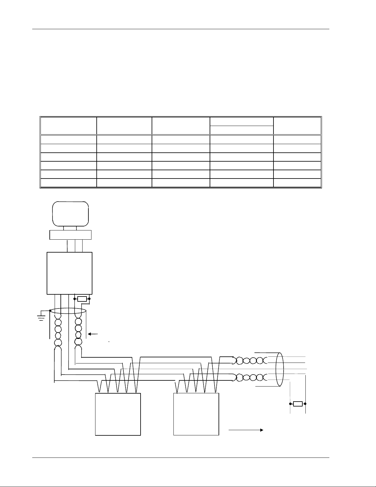
WIRING RS-422 (EIA-422) OR 4-WIRE RS-485 (EIA-485)
To use RS-422 (EIA-422), buffer the RS-232 (EIA-232) port of the PC with a suitable RS-232/422 (EIA-232)/422) converter. A
suitable commercially available Communications Converter unit is recommended for this purpose. Instruments on an RS-422
(EIA-422) communication network should be chain connected and not star connected.
To construct a cable for RS-422 (EIA-422) operation use a shielded cable with two twisted pairs plus a separate core for common.
Although common or shield connections are not necessary, their use will significantly improve noise immunity.
The terminals used for RS-422 (EIA-422) digital communications are listed in the table below.
Standard Cable PC socket pin no. PC Function * Instrument Terminal Instrument
Color 25 way CN2400 Function
White 3 Receive (RX+) HE Transmit (TX+)
Black 16 Receive (RX-) HF Transmit (TX-)
Red 12 Transmit (TX+) HB Receive (RX+)
Black 13 Transmit (TX-) HC Receive (RX-)
Green 7 Common HD Common
Shield 1 Ground
• These are the functions normally assigned to socket pins. Please check your PC manual to confirm.
Universal
Converter
Tx-
Tx+
PC
Com
Com
Rx
Rx-
RxTx
Tx
Rx
RS-422 (EIA-422)
RS-232 (EIA-232)
220 ohm
termination
resistor
on the Rx of the
converter unit
Figure 2-2 Controllers (1 to 31) Connected to a PC using
RS-422 (EIA-422) Standard
This diagram shows a typical installation.
It is possible to substitute an existing controller, or to add to
the current installation, with a CN2400 series controller
NOTES
Represents twisted pairs
provided it has been supplied as 4-wire EIA485.
To add any other CN2200 or CN2400 series please refer to
Figure 2-4
It is preferable to ground cable shield at both ends BUT it is
essential to ensure that both are at equipotential. If this
cannot be guaranteed ground at one end, as shown.
The value of terminating resistors is not critical,
100 - 300 ohms is typical.
220 ohm
Rx
Com
Controller 1
Tx+
Rx
Com
Controller 2
Tx+
Additional Controllers
termination
resistor on the Rx
terminals on last
controller in the
chain
WIRING 2-WIRE RS-485 (EIA-485)
2-4 Series CN2200 and CN2400 Communications Handbook
Page 9
Communications Handbook Digital Communications Hardware
Rx-
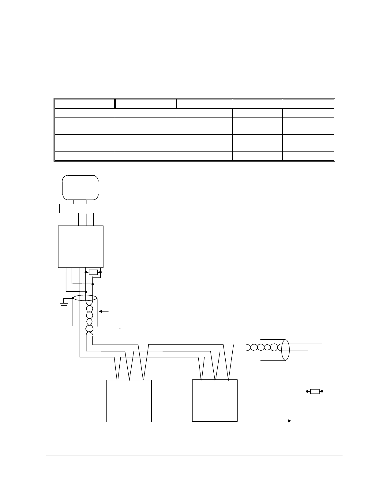
To use RS-485 (EIA-485), buffer the RS-232 (EIA-232) port of the PC with a suitable RS-232/485 (EIA-232)/485) converter.
Omega does not recommend the use of a RS-485 (EIA-485) board built into the computer since this board is unlikely to be isolated,
which may cause noise problems, and the Rx terminals are unlikely to be biased correctly for this application.
To construct a cable for RS-485 (EIA-485) operation use a shielded cable with one RS-485 (EIA-485)) twisted pair plus a separate
core for common. Although common or shield connections are not necessary, their use will significantly improve noise immunity.
The terminals used for RS-485 (EIA-485) digital communications are listed in the table below.
Standard Cable Color PC socket pin no. 25 way PC Function * Instrument Terminal Instrument Function
White 3 Receive (RX+) HF (b) or (B+) Transmit (TX)
Black 16 Receive (RX-)
Red 12 Transmit (TX+) HE (A) or (A+) Receive (RX)
Black 13 Transmit (TX-)
Green 7 Common HD Common
Shield 1 Ground
* These are the functions normally assigned to socket pins. Please check your PC manual to confirm .
PC
Tx-
Com
RxCom
Universal
Converter
Com
Tx+
RxTx
Tx
Rx
RS-485 (EIA-485)
Controller 1
Eg CN2400
RS-232 (EIA-232)
220 ohm
termination
resistor
on the Rx of the
converter unit
Twisted pairs
Com
HF HE
Figure 2-3 CN2000 Series Controllers (1 to 31) Connected
to a PC using 2-wire RS-485 (EIA-485) Standard
HF
Com
Controller 2
eg CN2200
HE
220 ohm
termination
resistor
on the last
controller in the
chain
Additional Controllers
Series CN2200 and CN2400 Communications Handbook 2-5
Page 10
Digital Communications Hardware Communications Handbook
Tx
Tx-RxRx-RxRx-TxTx-
HE
HF
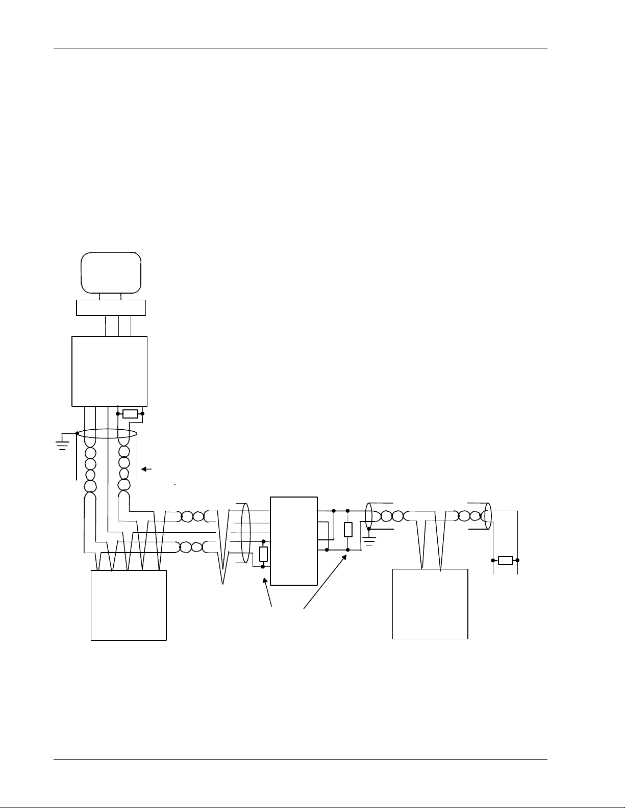
WIRING RS-422 (EIA-422) AND RS-485 (EIA-485) CONTROLLERS
It is generally not possible to connect controllers using a 2-wire standard to controllers on a 4-wire standard. This may be required,
for example, if the CN2200 or CN2400 series controllers are to be added to an existing installation. It is possible, however, to
modify the existing communications link by adding a universal communications converter. This is shown in figure 2-4 below.
The converter unit that converts from 232 to 4-wire 485 uses this link to communicate to the existing Omega controllers. The second
universal converter is a special version which converts from 4-wire to 2-wire 485 communications. It’s input side behaves to the 4wire link as another controller would on an existing system, while at the same time the communications messages from the computer
are passed onto the output side of this unit. This is connected to the 2-wire communications link that will contain the series CN2200
controllers. Any responses from controllers on this link will cause data to be placed on to the 4-wire link and then will be passed
back to the computer.
Figure 2-4
Com
PC
Tx
Rx
RS-232 (EIA-232)
Controllers (1 to 31) Connected to a PC using a mixed standard
of RS-422 (EIA-422) (or RS-485 (EIA-485) 4-wire) and RS-485
(EIA-485) 2-wire.
Tx
Rx
Com
Universal
Converter
Com
Tx- Rx
Tx+
Rx-
Rx
Rx-
Com
Controller 1
220 ohm
termination
resistor
on the Rx of the
converter unit
Twisted pairs
RS-422 (EIA-422)
Tx-
Tx+
Controller ‘n’
Universal Converter
220 ohm
termination
resistors
Rx
Tx
Controller n+1 to 31
CN2000/CN2400
220 ohm
termination
resistor
on the last
controller in
the 2-wire
chain
2-6 Series CN2200 and CN2400 Communications Handbook
Page 11
Communications Handbook Digital Communications Hardware
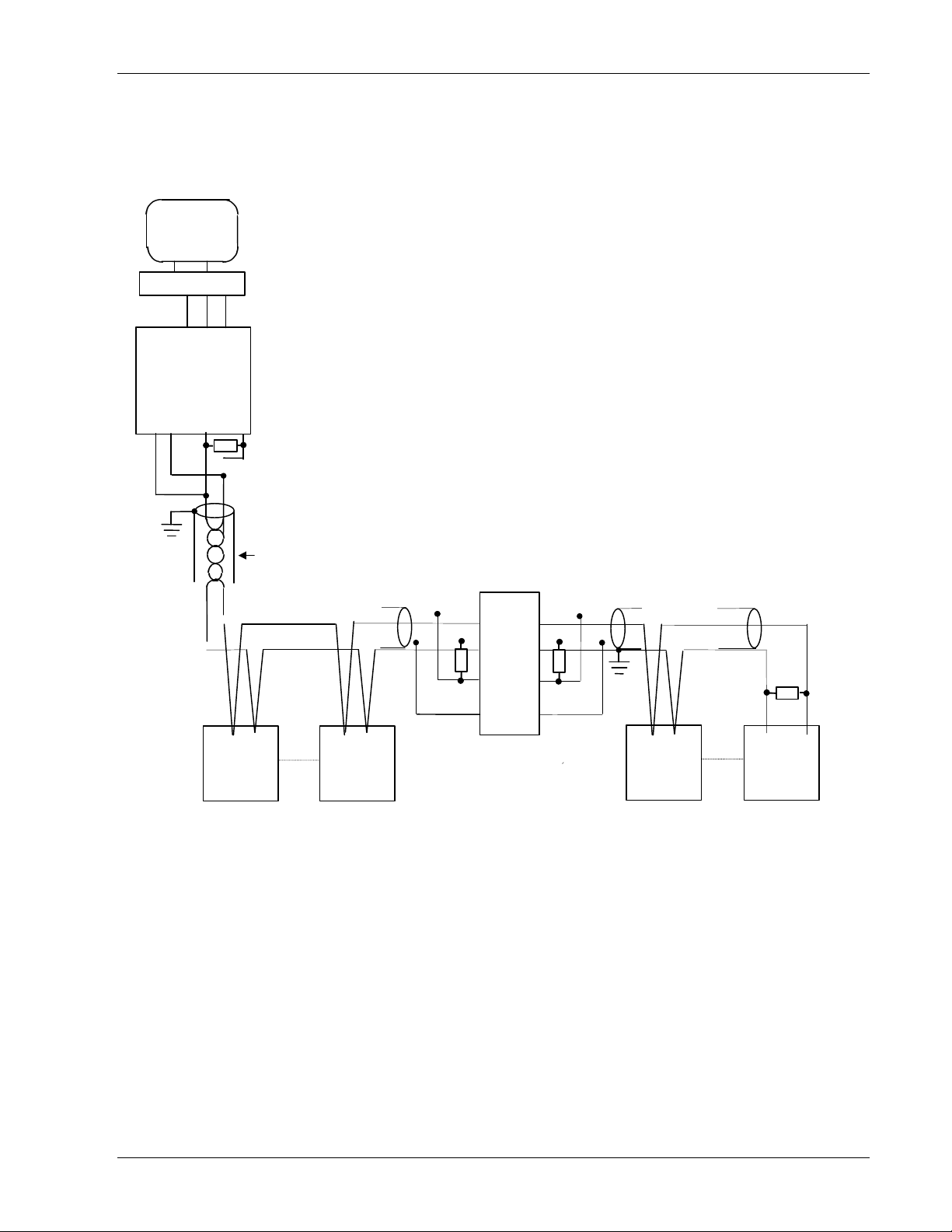
CONNECTIONS FOR UP TO 63 CONTROLLERS
Tx-
PC
Com
Universal
Converte
Com
Tx+
RxCom
Rx-
RxTx
Tx
Rx
It is allowable to substitute one instrument in the first group with a universal
comms isolator. Up to a further 31 additional instruments can be added as shown.
220 ohm
terminating
resistor
Twisted pairs
Figure 2-5
220 ohm
terminating
resistor
Rx+
Rx-
Rx+
Rx-
220 ohm
terminating
resistor
220 ohm
terminating
resistor on
the last
instrument
HF
HE
Instrument
1
HE
HF
Instrument
29
Tx+
Tx+
Tx-
Tx-
Universal
Converter
replaces one
Instrument
HFHE
Instrument
32
HF
HE
Instrument
63
Series CN2200 and CN2400 Communications Handbook 2-7
Page 12
Digital Communications Hardware Communications Handbook
Converter
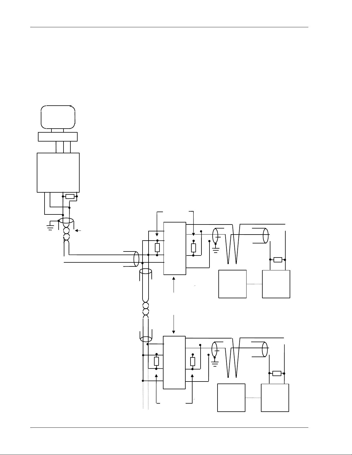
LARGE RS-422/485 (EIA422/485) NETWORKS
Networks with more than 32 instruments will require buffering of the communication lines. A commercialy available Universal
Converter unit is recommended for this purpose. The universal converter sets the transmit line to non-tristate.
NOTE Large networks using RS-422 (EIA-422) 4-wire controllers could use a Universal Converter Unit To set the transmit lines to non
tristate check the manual of the Universal Converter Unit. Contact Omega for further information when specifying large networks
Instruments on a RS-422/485 (EIA422/485) communication network should be chain connected and not star connected.
The diagram below illustrates the wiring of a network communicating with a large number of CN2200 and CN2400 Series controllers.
PC
Com
Tx
Rx
Tx
Rx
Com
Universal
Com
Tx-
Tx+
Rx-
Rx
220 ohm
terminating
resistor
220 ohm
terminating
resistor
220 ohm
terminating
resistor on
the last
controller
Twisted pairs
Repeat for further
controllers in the
chain
Rx+
Rx+
Rx-
Rx-
Tx+
Tx+
Tx-
Tx-
Universal
Converter
Rx+
Rx+
Rx-
Rx-
Tx+
Tx+
Tx-
Tx-
220 ohm
terminating
resistors
HF
HE
Controller
1
HE
HF
Controller
32
HE HF
Controller
31
220 ohm
terminating
resistor on
the last
controller
HF
HE
Controller
62
2-8 Series CN2200 and CN2400 Communications Handbook
Page 13
Communications Handbook Modbus® and JBUS® Protocol
CHAPTER 3 MODBUS® AND JBUS® PROTOCOL
This chapter introduces the principles of the MODBUS® and JBUS® communication protocols. Note that in the Series
CN2200/CN2400 the two protocols are identical, and both will be referred to as MODBUS® for the descriptions that follow.
PROTOCOL BASICS
A data communication protocol defines the rules and structure of messages used by all devices on a network for data exchange. This
protocol also defines the orderly exchange of messages, and the detection of errors.
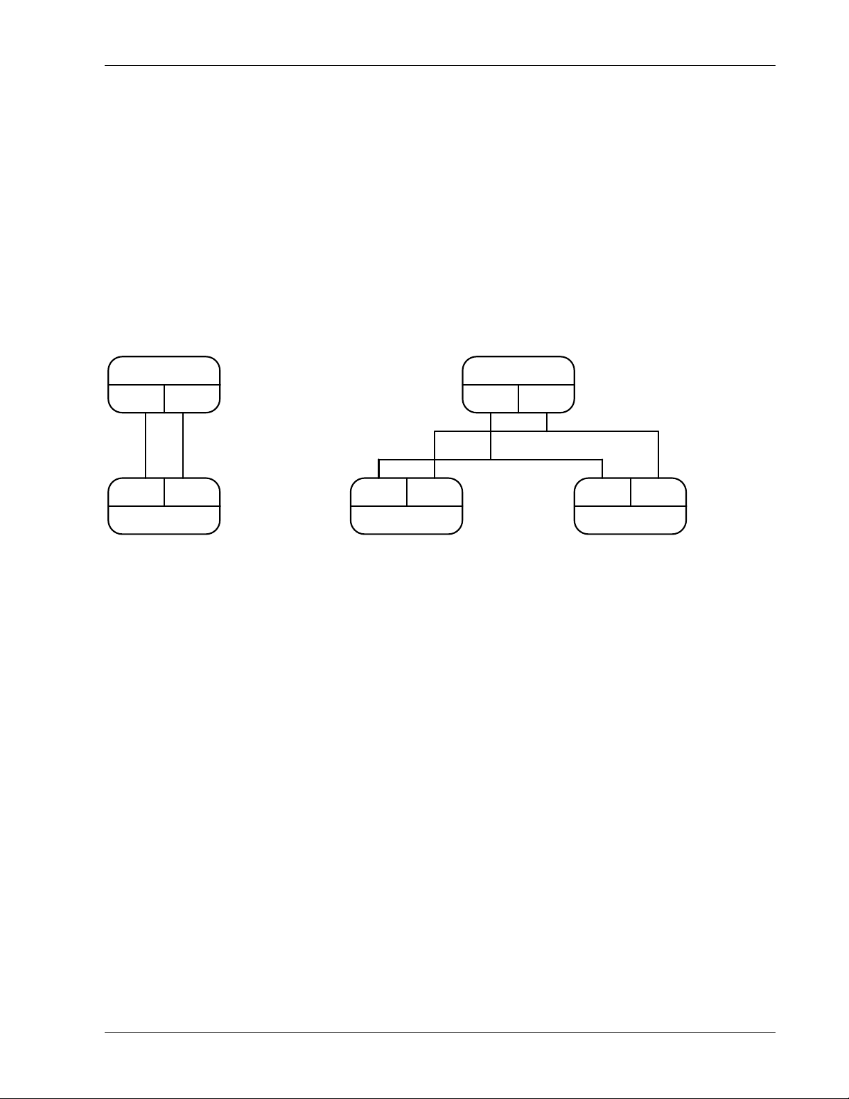
MODBUS® defines a digital communication network to have only one MASTER and one or more SLAVE devices. Either a single
or multi-drop network is possible. The two types of communications networks are illustrated in the diagram below;
Single Serial Link Multi Drop Serial Link
JBUS Master
TX RX
^
RS232
v
RX TX
JBUS Slave 1
A typical transaction will consist of a request sent from the master followed by a response from the slave.
The message in either direction will consist of the following information;
Device Address Function Code Data Error Check Data End of Transmission
v v
RX TX
JBUS Slave 1
^ ^
JBUS Master
TX RX
^
v
RS485
RX TX
JBUS Slave N
• Each slave has a unique 'device address'
• The device address 0 is a special case and is used for messages broadcast to all slaves. This is restricted to parameter write
operations.
• Series CN2200 and CN2400 support a subset of Modbus® function codes.
• The data will include instrument parameters referenced by a 'parameter address'
• Sending a communication with a unique device address will cause only the device with that address to respond. That
device will check for errors, perform the requested task and then reply with its own address, data and a check sum.
• Sending a communication with the device address '0' is a broadcast communication that will send information to all
devices on the network. Each will perform the required action but will not transmit a reply.
Series CN2200 and CN2400 Communications Handbook 3-1
Page 14
Modbus® and JBUS® Protocol Communications Handbook
TIME >
TYPICAL TRANSMISSION LINE ACTIVITY
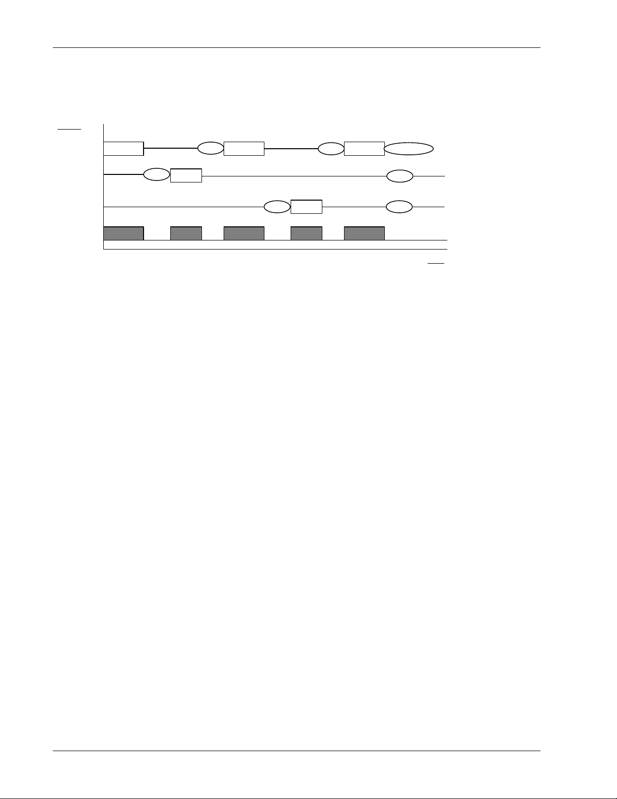
This diagram is to illustrate typical sequence of events on a Modbus® transmission line.
ACTIVITY
Master
Slave 1
Slave N
Network
To slave 1
Master
a
Reply
Slave 1
b
To slave N
Replya
Master Master
Slave 2
Broadcast
b
c
a
a
Period 'a' The processing time, (latency), required by the slave to complete the command and construct a reply.
Period 'b' The processing time required by the master to analyze the slave response and formulate the next command.
Period 'c' The wait time calculated by the master for the slaves to perform the operation. None of the slaves will reply to a broadcast
message.
For a definition of the time periods required by the network, refer to 'Wait Period' in the section 'Error Response'.
DEVICE ADDRESS
Each slave has a unique 8 bit device address. The Gould MODBUS® Protocol defines the address range limits as 1 to 247. Series
CN2200/CN2400 instruments will support an address range of 1 to 254. The device address used by the instrument is set using the
Addr parameter in the Cms List, which is available in operator mode. Note that this list may only be accessible when using the
FuLL user interface: refer to the manual supplied with the instrument for more details on how to set this parameter.
Device address 0 is a special case that will broadcast a message to all slave devices simultaneously.
3-2 Series CN2200 and CN2400 Communications Handbook
Page 15

Communications Handbook Modbus® and JBUS® Protocol
PARAMETER ADDRESS
Data bits or data words exchange information between master and slave devices. This data consists of parameters. All parameters
communicated between master and slaves have a 16 bit parameter address.
The MODBUS® parameter address range is 0001 to FFFF..
Parameter definitions for Series CN2200/CN2400 instruments are in Chapter 5.
PARAMETER RESOLUTION
JBUS® and MODBUS® protocol limit data to 16 bits per parameter. This reduces the active range of parameters to 65536 counts.
In Series CN2200 and CN2400 instruments this is implemented as -32767 (8001h) to +32767 (7FFFh).
The protocol is also limited to integer communication only. Series CN2200 and CN2400 instruments allow the user to configure either
integer or full resolution. In integer mode all parameters will be rounded to the nearest integer value, whereas in full resolution mode the
decimal point position will be implied so that 100.01 would be transmitted as 10001. From this, and the 16 bit resolution limitation, the
maximum value communicable with 2 decimal place resolution is 327.67. The parameter resolution will be taken from the slave user
interface, and the conversion factor must be known to both master and slave when the network is initiated.
MODE OF TRANSMISSION
The mode of transmission describes the structure of information within a message and the number coding system used to exchange a
single character of data.
The JBUS® and MODBUS® Protocols define a mode of transmission for both ASCII and RTU modes of transmission. Omega
Engineering Series CN2200 and CN2400 instruments only support the RTU mode of transmission.
The RTU definition of the mode of transmission for a single character is;
A start bit, eight data bits, a parity bit and one or two stop bits
All Omega Series CN2200 and CN2400 instruments use 1 stop bit.
Parity may be configured to be NONE, ODD or EVEN.
If parity is configured to be NONE, no parity bit is transmitted.
The RTU mode of transmission for a single character is represented as follows:
Start d7 d6 d5 d4 d3 d2 d1 d0 Parity Stop
Series CN2200 and CN2400 Communications Handbook 3-3
Page 16

Modbus® and JBUS® Protocol Communications Handbook
MESSAGE FRAME FORMAT
A message consists of a number of characters sequenced so that the receiving device can understand. This structure is known as
the message frame format.
The following diagram shows the sequence defining the message frame format used by JBUS® and MODBUS®:
Frame start Device address Function code Data CRC EOT
3 bytes 1 byte 1 byte n bytes 2 byte 3 bytes
The frame start is a period of inactivity at least 3.5 times the single character transmission time.
For example, at 9600 baud a character with 1 start, 1 stop and 8 data bits will require a 3.5ms frame start.
This period is the implied EOT of a previous transmission.
The device address is a single byte (8-bits) unique to each device on the network.
Function codes are a single byte instruction to the slave describing the action to perform.
The data segment of a message will depend on the function code and the number of bytes will vary accordingly.
Typically the data segment will contain a parameter address and the number of parameters to read or write.
The Cyclic Redundancy Check, (CRC) is an error check code and is two bytes, (16 bits) long.
The End of Transmission segment, (EOT) is a period of inactivity 3.5 times the single character transmission time. The EOT
segment at the end of a message indicates to the listening device that the next transmission will be a new message and therefore a
device address character.
CYCLIC REDUNDANCY CHECK
The Cyclic Redundancy Check, (CRC) is an error check code and is two bytes, (16 bits) long. After constructing a message, (data
only, no start, stop or parity bits), the transmitting device calculates a CRC code and appends this to the end of the message. A
receiving device will calculate a CRC code from the message it has received. If this CRC code is not the same as the transmitted
CRC there has been a communication error. Series CN2200 and CN2400 instruments do not reply if they detect a CRC error in
messages sent to them.
The CRC code is formed by the following steps:
1 Load a 16 bit CRC register with FFFFh.
2 Exclusive OR (⊕) the first 8 bit byte of the message with the with the high order byte of the CRC register.
Return the result to the CRC register.
3 Shift the CRC register one bit to the right.
4 If the over flow bit, (or flag), is 1, exclusive OR the CRC register with A001 hex and return the result to the
CRC register.
4a If the overflow flag is 0, repeat step 3.
5 Repeat steps 3 and 4 until there have been 8 shifts.
6 Exclusive OR the next 8 bit byte of the message with the high order byte of the CRC register.
7 Repeat step 3 through to 6 until all bytes of the message have been exclusive OR with the CRC register and shifted 8
times.
8 The contents of the CRC register are the 2 byte CRC error code and are added to the message with the most significant
bits first.
3-4 Series CN2200 and CN2400 Communications Handbook
Page 17
Communications Handbook Modbus® and JBUS® Protocol
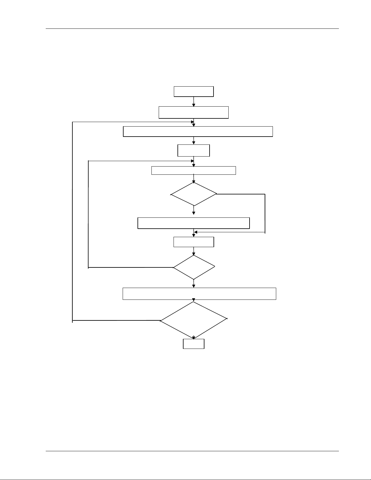
The flow chart below illustrates this CRC error check algorithm.
The '⊕' symbol indicates an 'exclusive OR' operation. 'n' is the number of data bits.
START
FFFFh → CRC Register
CRC Register ⊕ next byte of the message → CRC Register
0 → n
Shift CRC Register right 1 bit
NO
Over flow ?
YES
CRC Register ⊕ A001h → CRC Register
n + 1 → n
NO
CRC Register ⊕ next byte of the message → CRC Register
NO
n > 7 ?
YES
Is message complete ?
YES
END
Series CN2200 and CN2400 Communications Handbook 3-5
Page 18
Modbus® and JBUS® Protocol Communications Handbook
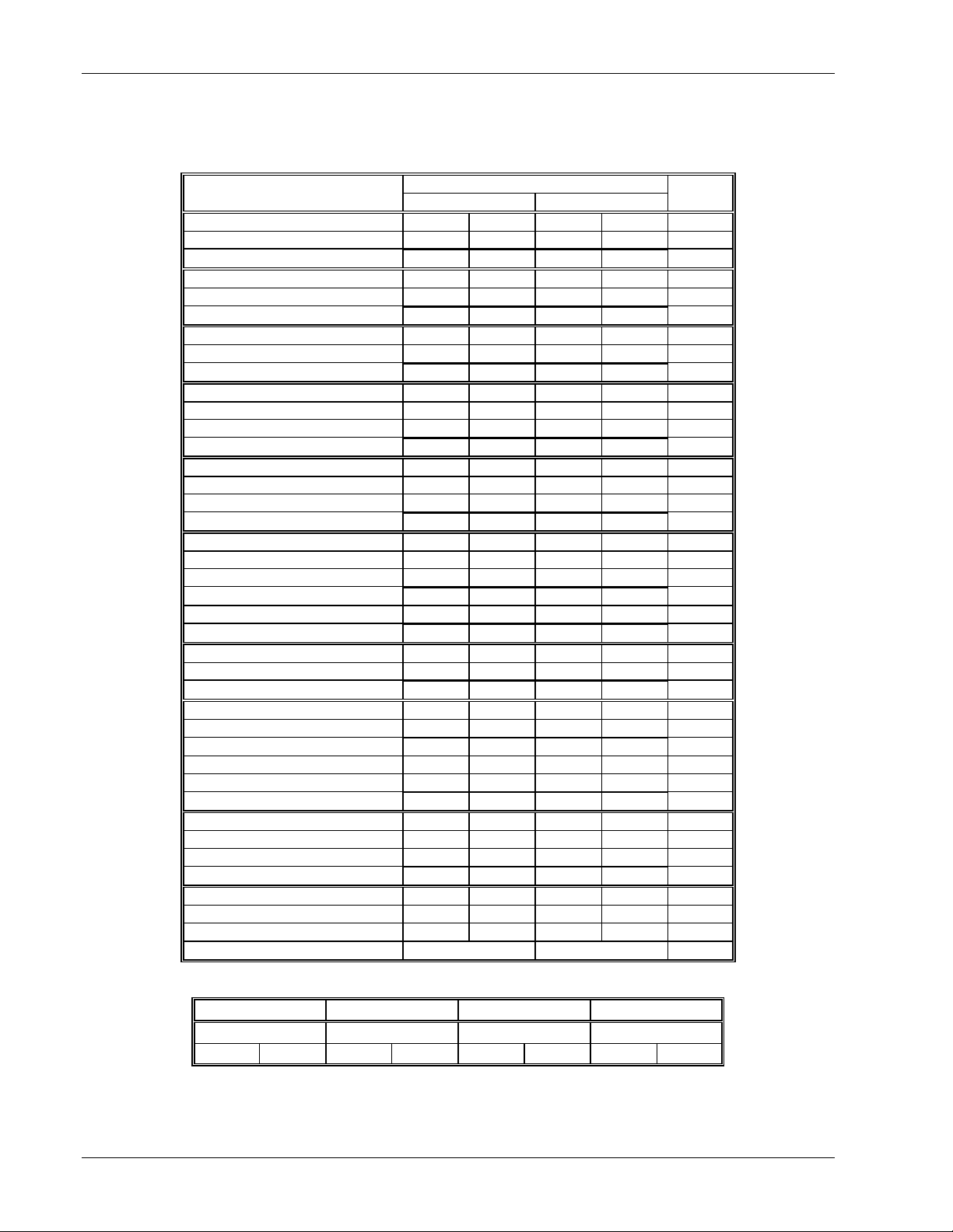
EXAMPLE OF A CRC CALCULATION
This example is a request to read from the slave unit at address 02, the fast read of the status (07).
Function 16 Bit Register Carry
LSB MSB flag
Load register with FFFF hex 1111 1111 1111 1111 0
First byte of the message (02) 0000 0010
Exclusive OR 1111 1111 1111 1101
1st shift right 0111 1111 1111 1110 1
A001 1010 0000 0000 0001
Exclusive OR (carry = 1) 1101 1111 1111 1111
2nd shift right 0110 1111 1111 1111 1
A001 1010 0000 0000 0001
Exclusive OR (carry = 1) 1100 1111 1111 1110
3rd shift right 0110 0111 1111 1111 0
4th shift right (carry = 0) 0011 0011 1111 1111 1
A001 1010 0000 0000 0001
Exclusive OR (carry = 1) 1001 0011 1111 1110
5th shift right 0100 1001 1111 1111 0
6th shift right (carry = 0) 0010 0100 1111 1111 1
A001 1010 0000 0000 0001
Exclusive OR (carry = 1) 1000 0100 1111 1110
7th shift right 0100 0010 0111 1111 0
8th shift right (carry = 0) 0010 0001 0011 1111 1
A001 1010 0000 0000 0001
Exclusive OR (carry = 1) 1000 0001 0011 1110
Next byte of the message (07) 0000 0111
Exclusive OR (shift = 8) 1000 0001 0011 1001
1st shift right 0100 0000 1001 1100 1
A001 1010 0000 0000 0001
Exclusive OR (carry = 1) 1110 0000 1001 1101
2nd shift right 0111 0000 0100 1110 1
A001 1010 0000 0000 0001
Exclusive OR (carry = 1) 1101 0000 0100 1111
3rd shift right 0110 1000 0010 0111 1
A001 1010 0000 0000 0001
Exclusive OR (carry = 1) 1100 1000 0010 0110
4th shift right 0110 0100 0001 0011 0
5th shift right (carry = 0) 0011 0010 0000 1001 1
A001 1010 0000 0000 0001
Exclusive OR (carry = 1) 1001 0010 0000 1000
6th shift right 0100 1001 0000 0100 0
7th shift right (carry = 0) 0010 0100 1000 0010 0
8th shift right (carry = 0) 0001 0010 0100 0001 0
CRC error check code 12h 41h
The final message transmitted, including the CRC code, is as follows;
Device address Function code CRC MSB CRC LSB
02h 07h 41h 12h
0000 0010 0000 0111 0100 0001 0001 0010
↑ First bit Transmission order Last bit ↑
3-6 Series CN2200 and CN2400 Communications Handbook
Page 19

Communications Handbook Modbus® and JBUS® Protocol
EXAMPLE OF A CRC CALCULATION IN THE ‘C’ LANGUAGE
This routine assumes that the data types ‘uint16’ and ‘uint8’ exists. These are unsigned 16 bit integer (usually an ‘unsigned short int’ for
most compiler types) and unsigned 8 bit integer (unsigned char). ‘z_p’ is a pointer to a Modbus® message, and z_message_length is its
length, excluding the CRC. Note that the Modbus® message will probably contain ‘NULL’ characters and so normal C string handling
techniques will not work.
uint16 calculate_crc(byte *z_p, uint16 z_message_length)
/* CRC runs cyclic Redundancy Check Algorithm on input z_p */
/* Returns value of 16 bit CRC after completion and */
/* always adds 2 crc bytes to message */
/* returns 0 if incoming message has correct CRC */
{
uint16 CRC= 0xffff;
uint16 next;
uint16 carry;
uint16 n;
uint8 crch, crcl;
while (z_message_length--) {
next = (uint16)*z_p;
CRC ^= next;
for (n = 0; n < 8; n++) {
carry = CRC & 1;
CRC >>= 1;
if (carry) {
CRC ^= 0xA001;
}
}
z_p++;
}
crch = CRC / 256;
crcl = CRC % 256
z_p[z_message_length++] = crcl;
z_p[z_message_length] = crch;
return CRC;
}
Example of a CRC Calculation in BASIC Language
Function CRC(message$) as long
'' CRC runs cyclic Redundancy Check Algorithm on input message$
'' Returns value of 16 bit CRC after completion and
'' always adds 2 crc bytes to message
'' returns 0 if incoming message has correct CRC
'' Must use double word for CRC and decimal constants
crc16& = 65535
FOR c% = 1 to LEN(message$)
crc16& = crc16& XOR ASC(MID$(message$, c%, 1))
FOR bit% = 1 to 8
IF crc16& MOD 2 THEN
crc16& = (crc16& \ 2) XOR 40961
ELSE
crc16& = crc16& \ 2
END IF
NEXT BIT%
NEXT c%
crch% = CRC16& \ 256: crcl% = CRC16& MOD 256
message$ = message$ + CHR$(crcl%) + CHR$(crch%)
CRC = CRC16&
END FUNCTION CRC
Series CN2200 and CN2400 Communications Handbook 3-7
Page 20

Modbus® and JBUS® Protocol Communications Handbook
FUNCTION CODES
Function codes are a single byte instruction to the slave describing the action to perform.
The following communication functions are supported by Series CN2200 and CN2400 instruments:
Function code Function
01 or 02 Read n bits
03 or 04 Read n words
05 Write a bit
06 Write a word
07 Fast Read of Status
08 Loopback
16 Write n words
It is recommended that function code 3 is used for reads and function code 16 is used for writes. This includes Boolean data. Other
codes are supplied for purposes of compatibility.
Only the write function codes 05, 06 and 16 will work with a ‘broadcast mode’ address. Series CN2200 and CN2400 instruments
will not reply if they receive a request including a unsupported function code.
Data bits or data words exchange information between master and slave devices. This data consists of parameters.
Parameter definitions for the Series CN2200 and CN2400 instruments are provided later in this document.
The sections that follow explain the message frame format for each function code.
3-8 Series CN2200 and CN2400 Communications Handbook
Page 21
Communications Handbook Modbus® and JBUS® Protocol
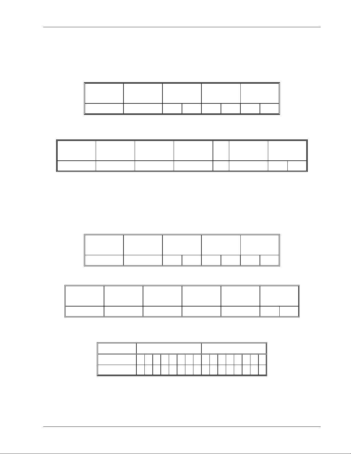
READ N BITS
Function code: 01 or 02, (01h or 02h)
Command:
Device address Function code
01 or 02
1 byte 1 byte MSB LSB MSB LSB MSB LSB
Address of
first bit
Number of bits to
read
CRC
Reply:
Device address Function code
01 or 02
1 byte 1 byte 1 byte 1 byte .... 1 byte MSB LSB
Number of bytes
read
First byte
of data
.... Last byte
of data
CRC
The first data byte contains the status of the first 8 bits, with the least significant bit being the first bit. The second data byte
contains the status of the next 8 bits, etc.. Unused bits are set to zero.
Example:From the instrument at device address 19, read 14 bits, beginning at parameter address 2.
Command:
Device address Function code Address of
first bit
Number of bits to
read
CRC
13 01 00 02 00 0E 1F 7C
Reply:
Device address Function code Number of bytes
read
13 01 02 01 01 C1 AF
First byte
of data
Second byte
of data
An expansion of the data bytes illustrates the relationship between data and the parameter addresses.
The reply indicates that the instrument is in sensor break and manual mode.
Data byte 1st byte (40h) 2nd byte (02h)
Param. address 9 8 7 6 5 4 3 2 17 16 15 14 13 12 11 10
Bit values 0 0 0 0 0 0 0 1 0 0 0 0 0 0 0 1
Parameter addresses 16 and 17 are set to zero.
CRC
Series CN2200 and CN2400 Communications Handbook 3-9
Page 22
Modbus® and JBUS® Protocol Communications Handbook
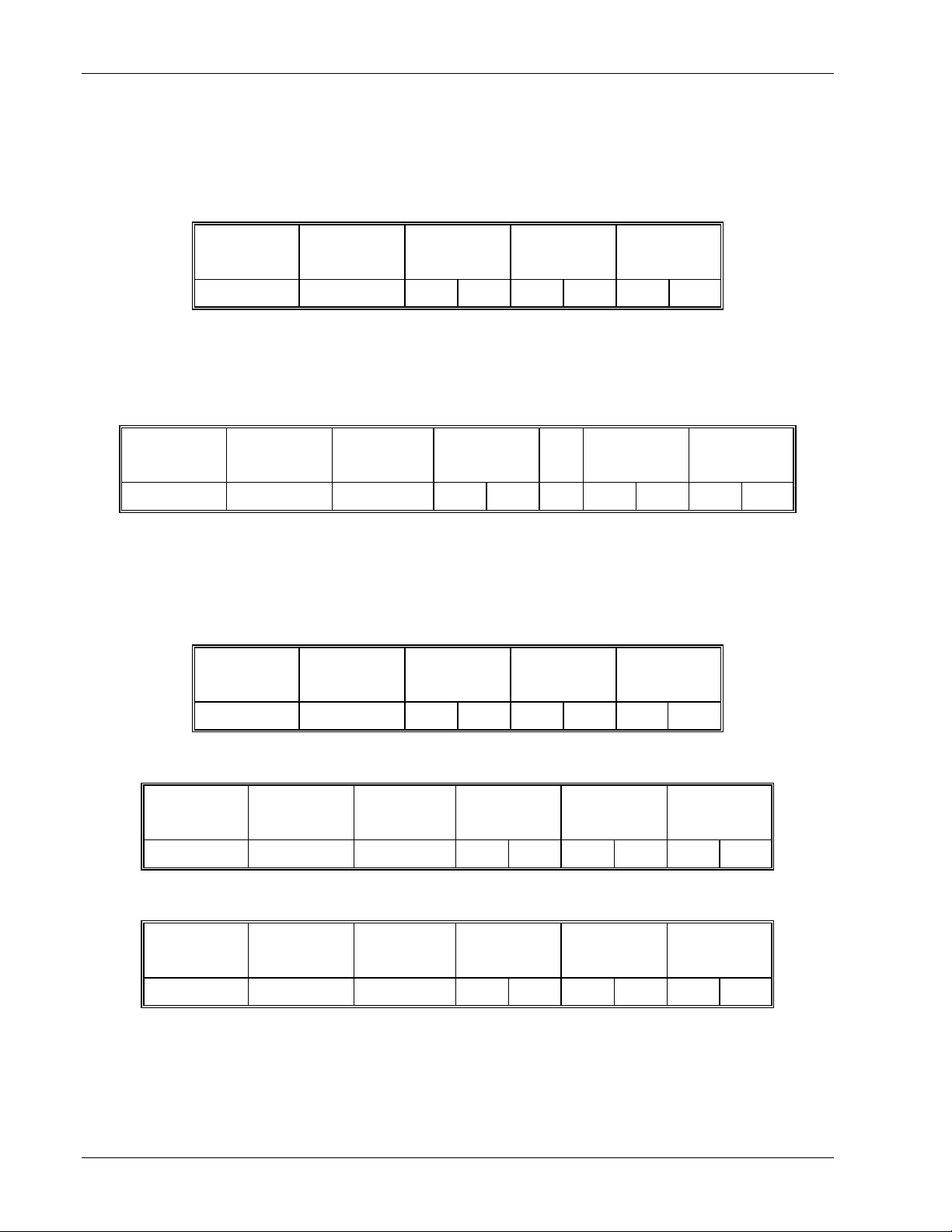
READ N WORDS
Function code: 03 or 04, (03h or 04h)
Command:
Device address Function code
03 or 04
1 byte 1 byte MSB LSB MSB LSB MSB LSB
Address of
first word
Number of words
to read
CRC
The maximum number of words that may be read is 125 for CN2400 Series instruments and 32 for the CN2200
Reply:
Device address Function code
03 or 04
1 byte 1 byte 1 byte MSB LSB .... MSB LSB MSB LSB
Number of bytes
read
Value of the first
word
.... Value of the last
word
CRC
Example: From CN2200 and CN2400 Series slave at device address 2, read 2 words from parameter address 1 (Process Variable and
Target Setpoint).
Command:
Device address Function code Address of
first word
Number of words
to read
CRC
02 03 00 01 00 02 95 F8
Reply: (If the instrument is configured with integer resolution and PV = 18.3, SP = 21.6)
Device address Function code
03 or 04
02 03 04 00 12 00 16 E8 F8
Number of bytes
read
Value of the first
word
Value of the last
word
Reply: (If the instrument is configured with full resolution and PV = 18.3, SP = 21.6)
Device address Function code
03 or 04
02 03 04 00 B2 00 D8 69 4E
Number of bytes
read
Value of the first
word
Value of the last
word
As the decimal point is not transmitted, the master must scale the response; 183=5.0, 216=10.0.
CRC
CRC
3-10 Series CN2200 and CN2400 Communications Handbook
Page 23
Communications Handbook Modbus® and JBUS® Protocol
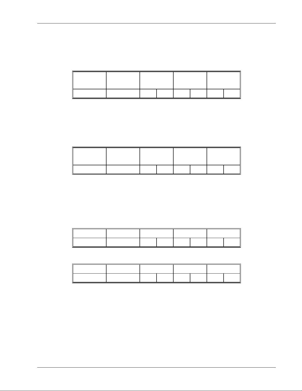
WRITE A BIT
Function code: 05, (05h)
Command:
Device address Function code05Address of bit Value of bit CRC
1 byte 1 byte MSB LSB MSB LSB MSB LSB
The LSB of 'Value of bit' is always set to 00. The MSB is used to write the value of the addressed bit.
To set a bit value of 1, either transmit 01h or FFh. To set a bit value of 0 transmit 00h.
A device address 00 will broadcast the data to all devices on the network.
Reply: (There will be no reply to a command broadcast to the device address 00.)
Device address Function code05Address of bit Value of bit CRC
1 byte 1 byte MSB LSB MSB LSB MSB LSB
The reply to function 05 is the same as the command. See the section on ‘Error Response’ below for details of
the reply if the operation fails.
Example:Write to the Series CN2200 and CN2400 instrument at device address 2 and set the instrument to manual.
(The bit at parameter address 2 is set).
Command:
Device address Function code Address of bit Value of bit CRC
02 05 00 02 01 00 6D A9
Reply:
Device address Function code Address of bit Value of bit CRC
02 05 00 02 01 00 6D A9
Series CN2200 and CN2400 Communications Handbook 3-11
Page 24
Modbus® and JBUS® Protocol Communications Handbook
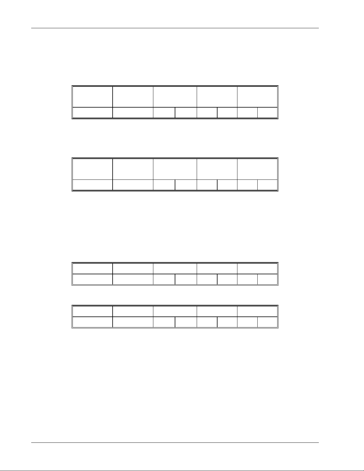
WRITE A WORD
Function code: 06, (06h)
Command:
Device address Function code06Address of word Value of word CRC
1 byte 1 byte MSB LSB MSB LSB MSB LSB
A device address 00 will broadcast the data to all devices on the network.
Reply: (There will be no reply to a command broadcast to the device address 00.)
Device address Function code06Address of word Value of word CRC
1 byte 1 byte MSB LSB MSB LSB MSB LSB
The reply to function 06 is the same as the command. See the section on ‘Error Response’ below for details of
the reply if the operation fails.
Example:Write to the Series CN2200 and CN2400 slave at device address 2 and change the setpoint to 25.0°C (address 2). The
instrument is configured with full resolution, therefore the required value is 250.
Command:
Device address Function code Address of word Value of word CRC
02 06 00 02 00 FA A8 7A
Reply:
Device address Function code Address of word Value of word CRC
02 06 00 02 00 FA A8 7A
3-12 Series CN2200 and CN2400 Communications Handbook
Page 25
Communications Handbook Modbus® and JBUS® Protocol
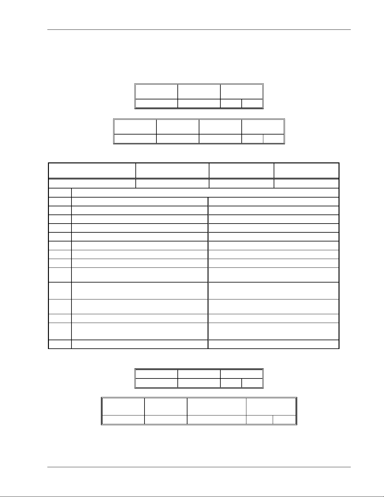
FAST READ OF STATUS
Function code: 07, (07h)
The fast read of status command is short to allow a rapid transaction to obtain one byte of frequently needed status information.
Command
Device address Function code
1 byte 1 byte MSB LSB
07
Reply:
Device address Function code
07
1 byte 1 byte 1 byte MSB LSB
Fast read
status byte
The table below defines the status byte information used by Series CN2200 and CN2400 instruments.
CRC
CRC
Parameter Modbus®
CN2400
Summary Output Status Word 75 75
BIT DESCRIPTION
0 Alarm 1 State ( 0 = Safe, 1 = Alarm ) Alarm 1 State ( 0 = Safe, 1 = Alarm )
1 Alarm 2 State ( 0 = Safe, 1 = Alarm ) Alarm 2 State ( 0 = Safe, 1 = Alarm )
2 Alarm 3 State ( 0 = Safe, 1 = Alarm ) Alarm 3 State ( 0 = Safe, 1 = Alarm )
3 Alarm 4 State ( 0 = Safe, 1 = Alarm ) Alarm 4 State ( 0 = Safe, 1 = Alarm )
4 Manual Mode ( 0 = Auto, 1 = Manual ) Manual Mode ( 0 = Auto, 1 = Manual )
5 Sensor Break ( 0 = Good PV, 1 = Sensor Broken ) Sensor Break ( 0 = Good PV, 1 = Sensor Broken )
6 Loop Break ( 0 = Good closed loop, 1 = Open Loop ) Loop Break ( 0 = Good Closed Loop, 1 = Open Loop )
7 Heater Fail ( 0 = No Fault, 1 = Load fault detected ) Heater Fail ( 0 = No Fault, 1 = Load Fault Detected)
8 Tune Active ( 0 = Auto Tune disabled, 1 = Auto Tune
active)
9 Ramp/Program Complete ( 0 = Running/Reset,
1 = Complete )
10 PV out of range ( 0 = PV within table range, 1 = PV out of
table range )
11 DC control module fault (0= Good,. 1= BAD) SSR Fail ( 0 = No fault, 1 = Load fault detected )
12 Programmer Segment Synchronize (0 = Waiting,
1 = Running)
13 Remote input sensor break (0 = Good, 1 = Bad) Remote input sensor break (0 = Good, 1 = Bad)
Modbus®
CN2200
Load Fail ( 0 = No Fault, 1 = Load Fault Detected)
Ramp/Program Complete ( 0 = Running/Reset, 1 =
Complete )
PV out of range ( 0 = PV within table range, 1 = PV out
of table range )
New Alarm
Display
-
Example: Fast read the status byte from a Series CN2200 and CN2400 instrument at device address 02.
Command:
Device address Function code CRC
02 07 41 12
Reply:
Device address Function code Fast read
status byte
02 07 30 D2 24
CRC
In this example the value of status byte (30h) has the following information;
PV is in sensor break
Instrument is in Manual mode
Series CN2200 and CN2400 Communications Handbook 3-13
Page 26
Modbus® and JBUS® Protocol Communications Handbook
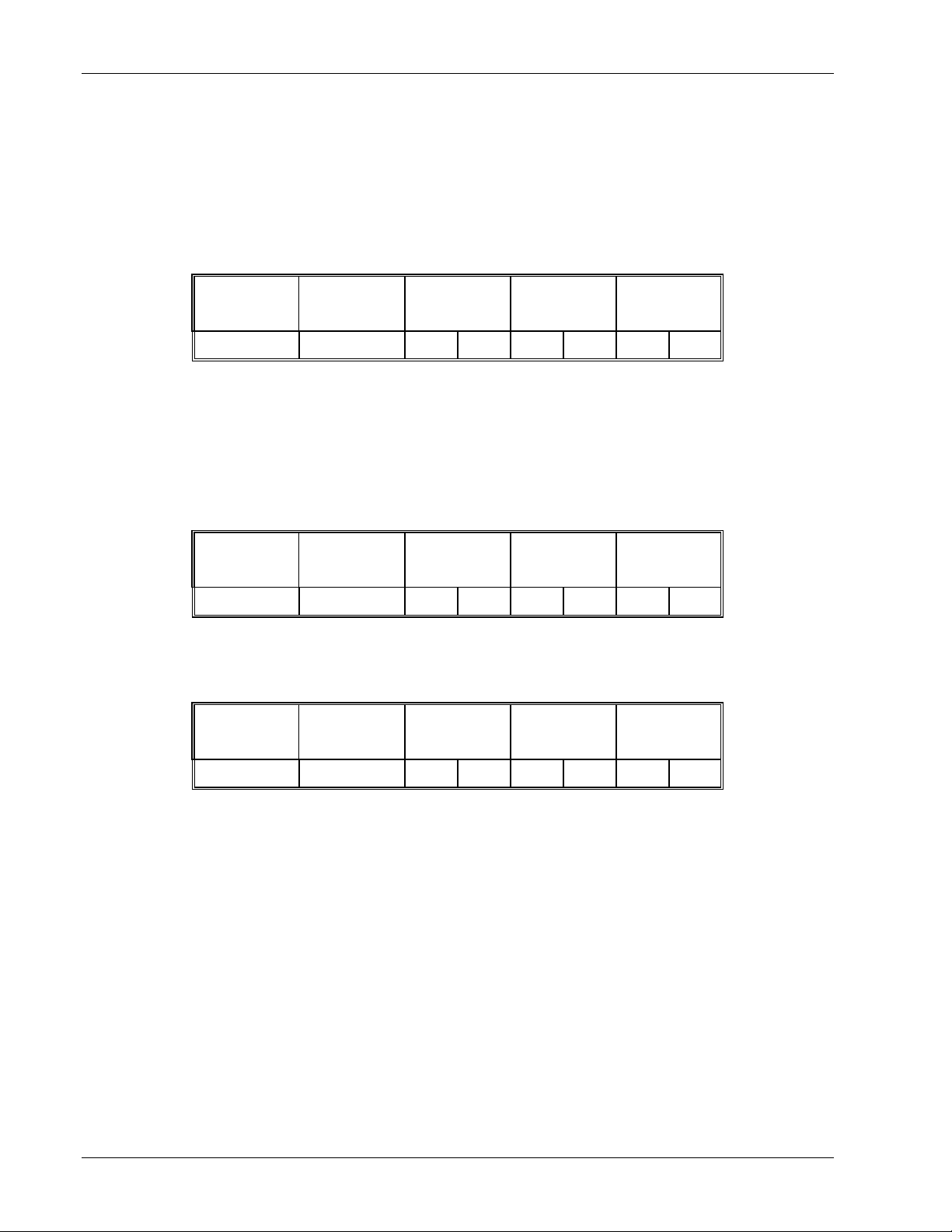
DIAGNOSTIC LOOPBACK
Function code: 08, (08h)
This function provides a means of testing the communications link by means of a ‘loopback’ operation. The data sent to the
instrument is returned unchanged. Only diagnostic code 0 from the Gould Modicon Specification is supported
Command:
Device address Function Code08Diagnostic Code
0000
1 byte 1 byte MSB LSB MSB LSB MSB LSB
Loopback Data CRC
Reply:
The reply to function 08 is the same as the command
Example: Perform a loopback from the Series CN2200 and CN2400 instrument at address 2, using a data value of 1234h.
Command:
Device address Function Code08Diagnostic Code
0000
02 08 00 00 12 34 ED 4F
Loopback Data CRC
Reply:
Device address Function Code08Diagnostic Code
Loopback Data CRC
0000
02 08 00 00 12 34 ED 4F
3-14 Series CN2200 and CN2400 Communications Handbook
Page 27
Communications Handbook Modbus® and JBUS® Protocol
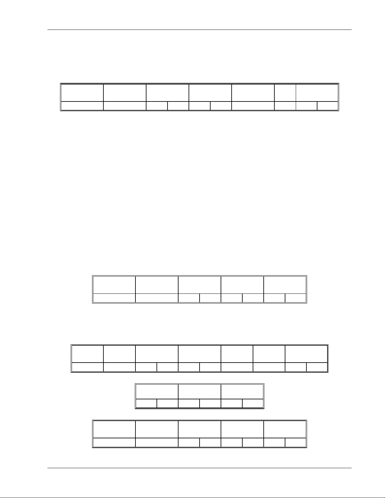
WRITE N WORDS
Function code: 16, (10h)
Command:
Device address Function code
10
1 byte 1 byte MSB LSB MSB LSB 1 byte n bytes MSB LSB
The maximum number of words that can be transmitted is
Series CN2200: 32
Series CN2400: 125 words, which corresponds to 250 bytes of data
The first two bytes are data with the required value of the first parameter, MSB first. Following pairs of bytes are data for the
consecutive parameter addresses.
A device address 00 will broadcast the data to all devices on the network.
NB: Blocks of data written using Modbus® function 16 containing values in positions corresponding to the addresses of
unconfigured parameters are not generally rejected, although the values of any unconfigured parameters are discarded. This
allows relatively large blocks of parameter data to be written in a single operation, even if the block contains a little ‘empty’ space.
This is particularly useful for operations such as downloading ramp/dwell programs, recipes, or instrument cloning. However, this
also leads to a potential pitfall: if the block of data contains only a single parameter, and the destination address refers to an
unconfigured or unused Modbus® address, the write operation will appear to be successful, although the instrument will have
discarded the value.
Address of
first word
Number of words
to write
Number of data
bytes (n)
Data CRC
Attempts to write to read only parameters over Modbus®, even when they are embedded within a block of data, will be rejected with
a Modbus® ‘data error’. Any subsequent values in the block will also be discarded.
Reply: There will be no reply to a command broadcast to the device address 00. See the section on ‘Error Response’ below for
details of the reply if the operation fails.
Device address Function code
10
1 byte 1 byte MSB LSB MSB LSB MSB LSB
Address of
first word
Number of words
written
CRC
Example: Write to the Series CN2200 and CN2400 slave at device address 2 which is configured with full resolution.
Setpoint 3 = 12.3 (123) parameter address 164
Setpoint 4 = 15.0 (150) parameter address 165
Setpoint 5 = 25.0 (250) parameter address 166
Command:
Device
address
02 10 00 A4 00 03 06 See below 20 71
Function
code
Address of
first word
Data (123) for
address 164
01 7B 03 96 00 FA
Number of words
to write
Data (150) for
address 165
Number of
data bytes
Data (250) for
address 166
Data CRC
Reply:
Device address Function code Address of
first word
02 10 00 A4 00 03 C1 D8
Number of words
written
CRC
Series CN2200 and CN2400 Communications Handbook 3-15
Page 28

Modbus® and JBUS® Protocol Communications Handbook
ERROR RESPONSE
The JBUS® and MODBUS® protocol define the response to a number of error conditions. A slave device is able to detect a
corrupted command or, one that contains an incorrect instruction, and will respond with an error code.
With some errors the slave devices on the network are unable to make a response. After a wait period the master will interpret the
failure to reply as a communication error. The master should then re-transmit the command.
A slave device that has detected a corrupted command or a command that contains an incorrect instruction, will respond with an
error message. The error message has the following syntax.
Device address Function code Error response
code
1 byte 1 byte 1 byte MSB LSB
CRC
The Function code byte contains the transmitted function code but with the most significant bit set to 1.
(This is the result of adding 128 to the function code.)
ERROR RESPONSE CODES
The error response code indicates the type of error detected.
Series CN2200 and CN2400 instruments support the following error response codes:
Code Error Description
02 Illegal Data Address The address referenced in the data field is not an
03 Illegal Data Value The value referenced in the data field is not allowable
allowable address for the slave
in the addressed slave location
3-16 Series CN2200 and CN2400 Communications Handbook
Page 29

Communications Handbook Modbus® and JBUS® Protocol
WAIT PERIOD
There are several errors for which the slave devices on the network are unable to make a response:
• If the master attempts to use an invalid address then no slave device will receive the message.
• For a message corrupted by interference, the transmitted CRC will not be the same as the internally calculated
CRC. The slave device will reject the command and will not reply to the master.
After a wait period, the master will re-transmit the command.
A wait period is also required after a broadcast communication to device address 0.
Caution: Failure to observe the wait period after a broadcast will negate the broadcast message.
The wait period should exceed the instrument latency plus the message transmission time. Typical wait periods, for a single
parameter read, are 20ms for Series CN2400 and 50 to 100ms for Series CN2200.
LATENCY
The time taken for the Series CN2200/CN2400 instruments to process a message and start the transmission of a reply is called the
latency. This does not include the time taken to transmit the request or reply.
The parameter functions read 1 word (function 03h), write 1 word (function 06h), write 1 bit (function 05h), fast read of status
(function 07h), and loopback (function 08h) are processed within a latency of between 2 and 10ms.
For the parameter functions, read n bits (function 01h), read n words (function 03h), and write n words (function 10h) the latency
is indeterminate. The latency will depend on the instrument activity and the number of parameters being transferred and will take
from 2 to 500ms, for Series CN2400, and 50 to 500ms, for Series CN2200.
It is possible to artificially increase the latency by setting the ‘Comms Delay’ parameter in the Mod HA configuration list. This is
sometimes required to allow a guaranteed gap between requests and responses, needed by some RS-485 (EIA-485) adaptors to
switch from transmit to receive states.
MESSAGE TRANSMISSION TIME
The time required to transmit a message will depend on the length of the message and the baud rate.
Message transmission time = (Number of bytes in the message + 3.5) * Number of bits per character
Baud rate
To find the number of bytes, refer to the relevant function code. The three extra bytes are for the End of Transmission, (EOT),
characters.
The number of bits per character will be ten, or eleven if a parity bit is used. (1 start bit, 8 data bits, an optional parity bit and 1
stop bit. See Mode of Transmission).
For example reading a single word with the function code 03 at 19200 baud, (no parity bit);
Command transmission time = (8 + 3.5) * 10 = 6 ms
19200
Reply transmission time = (9 + 3.5) * 10 = 6.5 ms
19200
The wait period for this transaction will exceed 22.5 ms, (6 + 6.5 + 10.0).
For a broadcast command, (device address 0), the master would not expect a reply. In this case, the wait period will exceed 16
ms, (6 +10.0).
Series CN2200 and CN2400 Communications Handbook 3-17
Page 30

Page 31

Communications Handbook Modbus® Addresses
CHAPTER 4 MODBUS® AND ADDRESSES
MODBUS® ADDRESS
This section of the manual provides a list of all parameters in Series CN2200 and CN2400 controllers that are available over the
communications link. As far as possible, it follows the same organization as the controller user interface itself. Definitions of
parameters and status information not available via the controller display are also provided.
Series CN2200 and CN2400 controllers may be configured for a wide variety of functions and some parameters will only be
available if the related function is configured. Modbus® addresses that are not supported have no parameter assigned. In normal
operating mode all configuration parameters are read only. To be able to write to these parameters, the controller must be in
configuration mode.
If the Modbus® protocol is used to read a parameter that is not configured, an undefined value will be returned.
Modbus® function 6 single parameter write operations to unconfigured or read only parameters will be rejected with a Modbus®
‘data error’ return code.
NB: Blocks of data written using Modbus® function 16 containing values in positions corresponding to the addresses of
unconfigured parameters are not generally rejected, although the values of any unconfigured parameters are discarded. This
allows relatively large blocks of parameter data to be written in a single operation, even if the block contains a little ‘empty’ space.
This is particularly useful for operations such as ramp/dwell program downloading, recipes, or instrument cloning. However, this
also leads to a potential pitfall: if the block of data contains only a single parameter, and the destination address refers to an
unconfigured or unused Modbus® address. The write operation will appear to be successful, although the controller will have
discarded the value.
Attempts to write to read only parameters over Modbus®, even when they are embedded within a block of data, will be rejected with
a Modbus® ‘data error’. Any subsequent values in the block will also be discarded.
Rules for read and write operation in the Modbus® IEEE are dealt with in Chapter 3.
Series CN2200 and CN2400 Communications Handbook 4-1
Page 32
Modbus® Addresses Communications Handbook
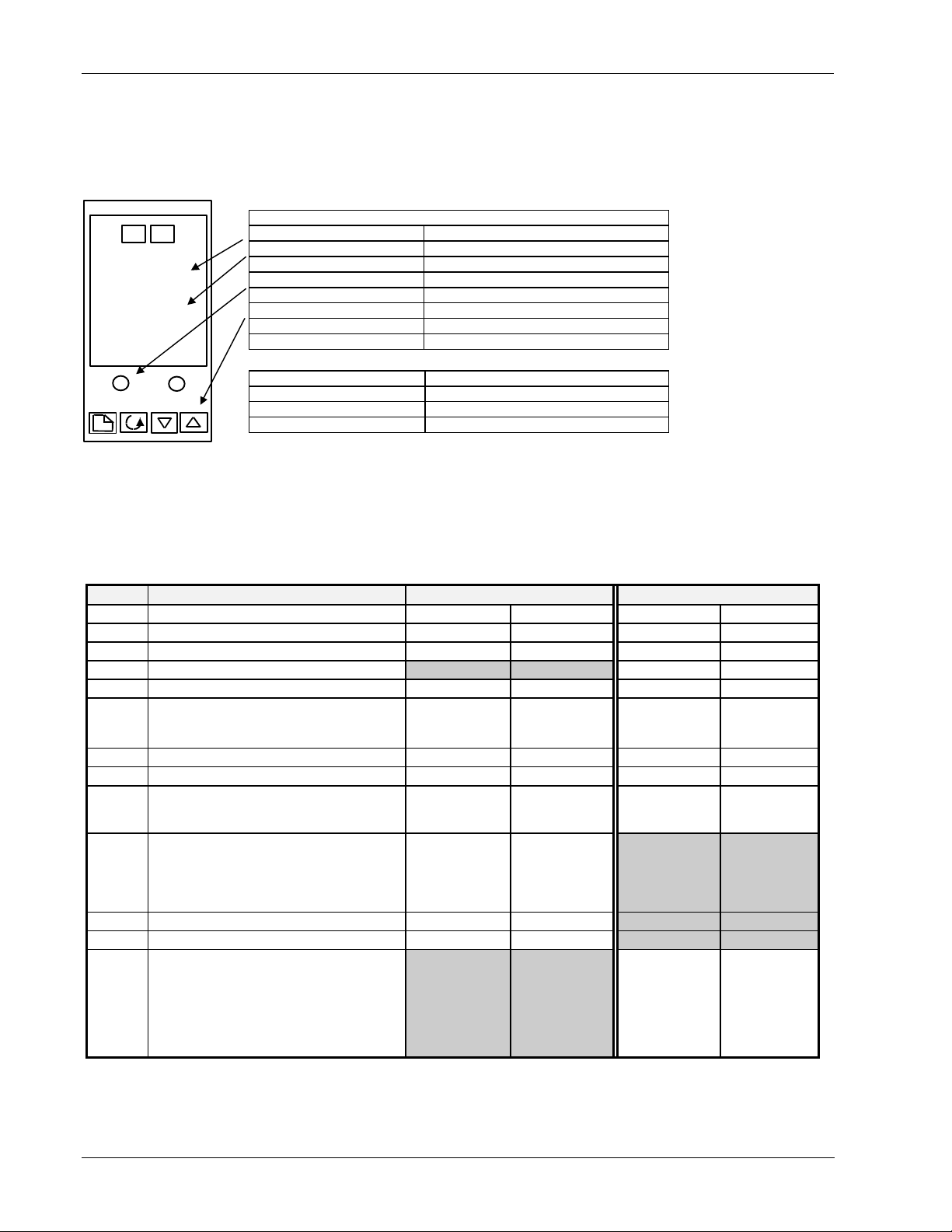
OPERATING MODE PARAMETERS
It is often only necessary to access a limited number of the most common parameters, where, for example, it is required to emulate
the front panel of a controller in a mimic diagram. The following table shows a summary of common parameters:
CN2408
OP2OP1
20.00
23.00
Example 1 PID Controller
Parameter Modbus® Address
Read Process value 1
Change Setpoint 2 - (enter new value)
Raise Setpoint 2 - (new value in repeated steps)
Select Manual Mode 273 - (enumerator 1)
Change Output Power 3 - (new value)
Raise Output Power 3 - (new value in repeated steps)
Read Output Power 3
Parameter Modbus® address
To Select Manual 273 - (enumerator 1)
To Change Output Position 60 - (new value)
To Read Output Position 53
MODBUS® TABLES
Notes: The following notes apply throughout this section
1. Issued software versions to date are CN2400: 1.03, 2.04, 3.04 and 3.05 and 2200: 1.00, 1.20, 1.30 and 2.10.
2. Greyed out cells indicate parameter not available
CN2400 CN2200
1 1
3 3
53
2 2
273 273
80 80
629 629
5 5
85 See Note 1
above
60
53
106
OPOP
vPoSvPoS
SPSP
m-Am-A
AmPSAmPS
C.idC.id
w.SPw.SP
OPOP
--
-diSPdiSP
Home list
Modbus® Notes Modbus® Notes
Process Variable
% Output level
Valve position
Target setpoint (if in Manual mode )
Auto-man select
0: Auto
1: Manual
Heater current (With PDLINK mode 2)
Customer defined identification number
Working set point. Read only: use Target
set point or currently selected set point (1
to 16) to change the value
Control output (on/off controller). Not writable
unless the controller is in ‘manual’ mode.
0: -100%
1: 0%
2: 100%
VP Manual Output (alterable in Man only)
Valve Posn (computed by VP algorithm)
Display
0: Standard
1: Load current
2: Output power
3: Program state
5: Blank
6: Valve position
4-2 Series CN2200 and CN2400 Communications Handbook
Page 33
Communications Handbook Modbus® Addresses
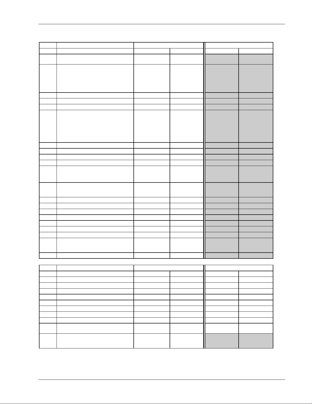
runrun
PrgPrg
StAtStAt
PSPPSP
CYCCYC
SEGSEG
StYPStYP
SEGtSEGt
tGttGt
rAtErAtE
PrGtPrGt
FAStFASt
out.1out.1
out.2out.2
out.3out.3
out.4out.4
out.5out.5
out.6out.6
out.7out.7
out.8out.8
SyncSync
SEG.dSEG.d
Run List CN2400 CN2200
Modbus® Notes Modbus® Notes
Current program running (active prog
no.)
Program Status
1: Reset
2: Run
4: Hold
8: Holdback
16: Complete
Programmer setpoint 163
Program cycles remaining 59
Current segment number 56
Current segment type
0: End
1: Ramp (Rate)
2: Ramp (Time to target)
3: Dwell
4: Step
5: Call
Segment time remaining 36
Target setpoint (current segment) 160
Ramp rate 161
Program time remaining 58
Fast run
0: No
1: Yes
Logic 1 output (current program)
0: Off (applies to all 8 logic outputs)
1: On (applies to all 8 logic outputs)
Logic 2 output (current program) 465
Logic 3 output (current program) 466
Logic 4 output (current program) 467
Logic 5 output (current program) 468
Logic 6 output (current program) 469
Logic 7 output (current program) 470
Logic 8 output (current program) 471
Segment synchronization
0: No
1: Yes
Flash active segment in lower display 284
22
23
29
57
464
488
Alarm List CN2400 CN2200
ALAL
Modbus® Notes Modbus® Notes
1---1--2---2--3---3--4---4---
HY1HY1
Hy2Hy2
HY3HY3
HY4HY4
LbtLbt
diAGdiAG
Alarm 1setpoint value 13 13
Alarm 2setpoint value 14 14
Alarm 3setpoint value 81 81
Alarm 4setpoint value 82 82
Alarm 1 hysteresis 47 580
Alarm 2 hysteresis 68 580
Alarm 3 hysteresis 69 580
Alarm 4 hysteresis 71 580
Loop break time
0: Off
Enable diagnostic messages
0: No Diagnostics
1: Diagnostics
83 83
282
Series CN2200 and CN2400 Communications Handbook 4-3
Page 34
Modbus® Addresses Communications Handbook
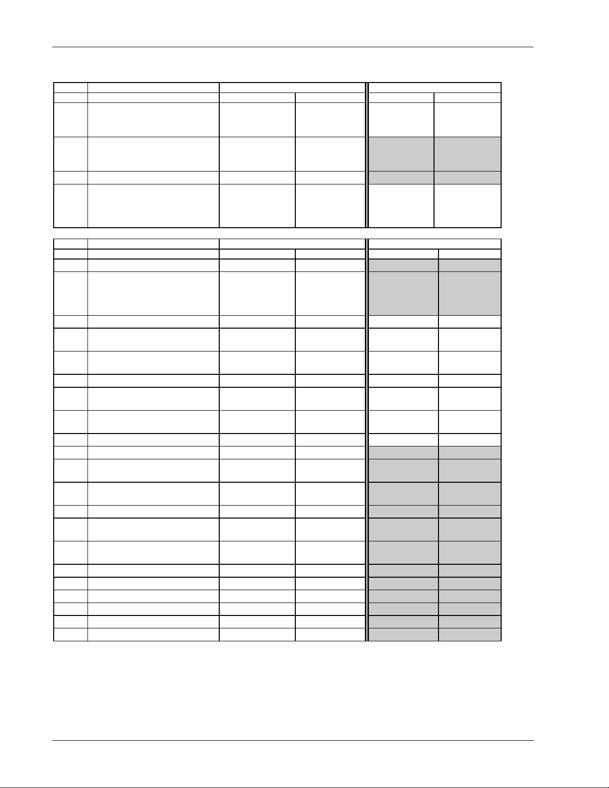
AtunAtun
tunEtunE
drAdrA
dra.tdra.t
adcadc
PidPid
G.SPG.SP
SETSET
PBPB
TiTi
tdtd
resres
HcbHcb
LcbLcb
reL.creL.c
pb2pb2
ti2ti2
td2td2
res.2res.2
Hcb2Hcb2
Lcb2Lcb2
reL2reL2
pb.cpb.c
db.cdb.c
ff.pbff.pb
ff.trff.tr
ff.dvff.dv
Autotune List CN2400 CN2200
Modbus® Notes Modbus® Notes
Autotune enable
0: No Tune
1: Tune
Adaptive tune enable
0: No Adaptive Tune
1: Tune
Adaptive tune trigger level 100
Automatic droop compensation
(manual reset)
0: Manual reset
1: Calculated
PID List CN2400 CN2200
Gain scheduler setpoint 153
Current PID set (read only if gain
scheduling is selected)
0: Set 1
1: Set 2
Proportional band PID1 6 6
Integral time PID1
0: Off
Derivative time PID1
0: Off
Manual reset PID1 28 28
Cutback high PID1
0: Auto
Cutback low PID1
0: Auto
Relative cool gain PID1 19 19
Proportional band PID2 48
Integral time PID2
0: Off
Derivative time PID2
0: Off
Manual reset PID2 50
Cutback high PID2
0: Auto
Cutback low PID2
0: Auto
Relative cool gain PID2 52
Cool proportional band 90
Cool deadband 91
Feedforward proportional band 97
Feedforward trim 98
Feedforward trim limit 99
270 270
271
272 272
Modbus® Notes Modbus® Notes
72
8 8
9 9
18 18
17 17
49
51
118
117
4-4 Series CN2200 and CN2400 Communications Handbook
Page 35
Communications Handbook Modbus® Addresses
On.OFOn.OF
hys.Hhys.H
hys.Chys.C
HC.dbHC.db
sb.OPsb.OP
mtrmtr
tmtm
In.tIn.t
bac.tbac.t
mp.tmp.t
v.brv.br
sb.opsb.op
mtrmtr
cyc.tcyc.t
InvInv
IndInd
bAc.ubAc.u
bAc.dbAc.d
VEL.uVEL.u
VEL.dVEL.d
Pot.LPot.L
Pot.HPot.H
Sb.OPSb.OP
On/Off List CN2400 CN2200
Modbus® Notes Modbus® Notes
Heat hysteresis 86 These 86
Cool hysteresis 88 parameters 88
Heat/cool deadband 16 appear in 16
On/Off sensor break output power
0: -100%
1: 0%
2: 100%
Motor List CN2400 CN2200
Valve travel time 21
Valve inertia time 123
Valve backlash time 124
Minimum pulse time 54
Bounded sensor break strategy 128
VP Bounded sensor break 62 VP b (feedback)
Motor List CN2400 CN2200
VP Cycle time 132
VP Raise inertia
0: Off
VP Lower inertia
0: Off
VP Raise backlash
0: Off
VP Lower backlash
0: Off
VP Raise velocity limit 125
VP lower velocity limit 126
VP Position low limit 42
VP Position high limit 43
Boundless sensor break o/p
0: Rest
1: Up
2: Down
40 the output list in
2400 series
Modbus® Notes Modbus® Notes
controllers only
Modbus® Notes Modbus® Notes
123
130
124
129
128
Series CN2200 and CN2400 Communications Handbook 4-5
Page 36
Modbus® Addresses Communications Handbook
SPSP
sseLsseL
L-rL-r
sp 1sp 1
sp 2sp 2
sp 3sp 3
sp 4sp 4
SP 5SP 5
SP 6SP 6
SP 7SP 7
SP 8SP 8
SP 9SP 9
SP 10SP 10
SP 11SP 11
SP 12SP 12
SP 13SP 13
SP 14SP 14
SP 15SP 15
SP 16SP 16
rm.SPrm.SP
rmt.trmt.t
rATrAT
Loc.tLoc.t
SP LSP L
SP HSP H
SP2.LSP2.L
SP2.HSP2.H
Loc.LLoc.L
Loc.HLoc.H
SPrrSPrr
Hb.tYHb.tY
HbHb
SPSP
Setpoint list CN2400 CN2200
Modbus® Notes Modbus® Notes
Select setpoint
0: SP1
1: SP2
2: SP 3
3: SP 4
4: SP 5
5: SP 6
6: SP 7
7: SP 8
8: SP 9
9: SP 10
10: SP 11
11: SP 12
12: SP13
13: SP14
14: SP15
15: SP16
Local or remote setpoint select
0: Local
1: Remote
Setpoint 1 24 24
Setpoint 2 25 25
Setpoint 3 164
Setpoint 4 165
Setpoint 5 166
Setpoint 6 167
Setpoint 7 168
Setpoint 8 169
Setpoint 9 170
Setpoint 10 171
Setpoint 11 172
Setpoint 12 173
Setpoint 13 174
Setpoint 14 175
Setpoint 15 176
Setpoint 16 177
Remote setpoint 485 26
Remote setpoint trim 486
Ratio setpoint 61
Local setpoint trim 27 27
Setpoint 1 low limit 112 112
Setpoint 1 high limit 111 111
Setpoint 2 low limit 114 114
Setpoint 2 high limit 113 113
Local setpoint trim low limit 67 67
Local setpoint trim high limit 66 66
Setpoint rate limit
0: Off
Holdback type for setpoint rate limit
0: Off
1: Low
2: High
3: Band
Holdback value for setpoint rate limit 65
Setpoint List CN2400 CN2200
15 SP1 & SP2
available in
standard controller
SP1 to SP16
available to order in
the 16 setpoint
option
276 276
35 35
70
15 SP1 & SP2
available in
standard
controller
SP1.LSP1.L
SP1.HSP1.H
4-6 Series CN2200 and CN2400 Communications Handbook
Page 37
Communications Handbook Modbus® Addresses
Modbus® Notes Modbus® Notes
Dwell segment 0: Off 62
Go to state at end of program
0: Dwell
1: Reset
2: Hold
3: Standby
Program state write
1: Reset
2: Run
Program state read
1: Off
2: Run
4: Hold
16 End
32: Dwell
64 Ramp
517
57
23
End.tEnd.t
ProGProG
statstat
iPiP
FiLtFiLt
FiLt.2FiLt.2
F.1F.1
F.2F.2
Hi.1PHi.1P
Lo.1PLo.1P
EmiSEmiS
EmiS.2EmiS.2
PV.iPPV.iP
CALCAL
CAL.SCAL.S
CAL.LCAL.L
Adj.LAdj.L
CAL.HCAL.H
AdJ.HAdJ.H
AdJAdJ
AdJAdJ
OFS.1OFS.1
OFS.2OFS.2
mV.1mV.1
mV.2mV.2
CJC.1CJC.1
CJC.2CJC.2
Li.1Li.1
Li.2Li.2
PV.SLPV.SL
Input List CN2400 CN2200
Modbus® Notes Modbus® Notes
Input 1 filter time constant 0: Off 101 101
Input 2 filter time constant 0: Off 103
Derived input function factor 1 292
Derived input function factor 2 293
Switchover transition region high 286 Input
Switchover transition region low 287 switching
Emmisivity 38 Custom
Emmisivity input 2 104 pyrometers
Select input 1 or input 2 288
User calibration enable
0: Factory
1: User
Selected calibration point
0: None
1: Input 1 low
2: Input 1 high
3: Input 2 low
4: Input 2 high
Transducer Low Cal enable
0: No
1: Yes
Adjust low calibration point 145
Transducer High Cal enable
0: No
1: Yes
Adjust high calibration point 144
User calibration adjust input 1 146 63
User calibration adjust input 2 148
Input 1 calibration offset 141 127
Input 2 calibration offset 142
Input 1 measured value 202 202
Input 2 measured value 208
Input 1 cold junction temp. reading 215 215
Input 2 cold junction temp. reading 216
Input 1 linearized value 289
Input 2 linearized value 290
Currently selected setpoint 291
110 110
102 108
109
108
0: None
1: Adj low
2: Adj hi
3: N/A
4: N/A
OFStOFSt
mVmV
CJCCJC
Series CN2200 and CN2400 Communications Handbook 4-7
Page 38
Modbus® Addresses Communications Handbook
oPoP
OP.LoOP.Lo
OP.HiOP.Hi
rOP.LrOP.L
rOP.HrOP.H
OprrOprr
FOPFOP
CYC.HCYC.H
hYs.HhYs.H
ont.Hont.H
CYC.CCYC.C
hYs.ChYs.C
ont.Cont.C
HC.dbHC.db
Sb.OPSb.OP
cmScmS
AddrAddr
Output List CN2400 CN2200
Modbus® Notes Modbus® Notes
Low power limit 31 31
High power limit 30 30
Remote low power limit 33
Remote high power limit 32
Output rate limit
0: Off
Forced output level 84
Heat cycle time 10 10
Heat hysteresis (on/off output) 86
Heat output minimum on time
0: Auto
Cool cycle time 20 20
Cool hysteresis (on/off output) 88
Cool output minimum on time
0: Auto
Heat/cool deadband (on/off output) 16
Sensor break output power 34 34
Comms. List CN2400 CN2200
Communications address 131 131
37
45 45
89 89
Modbus® Notes Modbus® Notes
4-8 Series CN2200 and CN2400 Communications Handbook
Page 39
Communications Handbook Modbus® Addresses
inFoinFo
diSPdiSP
LoG.LLoG.L
LoG.HLoG.H
LoG.ALoG.A
LoG.tLoG.t
LoG.vLoG.v
rES.LrES.L
mCtmCt
w.OPw.OP
SSrSSr
FF.OPFF.OP
P OPP OP
I OPI OP
d OPd OP
VELVEL
vP SvP S
Information List CN2400 CN2200
Modbus® Notes Modbus® Notes
Configuration of lower readout
display
0: Standard
1: Load current
2: Output power
3: Status
4: Program time
5: None
6: Valve position
7: Process value 2
8: Ratio setpoint
9: Selected program number
10: Remote setpoint
PV minimum 134
PV maximum 133
PV mean value 135
Time PV above threshold level 139
PV threshold for timer log 138
Logging reset
0: Not reset
1: Reset
Processor utilization factor 201
Working output 4
PDLINK SSR status
0: Good
1: Load fail
2: Open
3: Heater fail
4: SSR fail
5: Sn fail
Feedforward component of output 209
Proportional component of output 214
Integral component of output 55
Derivative component of output 116
VP velocity signal 219
VP motor calibration state
0: Start
1: Waiting
2: Open valve
3: BLUp/InDn
4: Ttup
5: Overshoot
6: InUp/BLDn
7: TT down
8: Open
9: Low lim
10: Stopping
11: Raise
12: Inert up
13: Lower
14: Low lim
15: Stopping
16: Lower
17: InDn/BL
99: Abort
106
140
79
210
Series CN2200 and CN2400 Communications Handbook 4-9
Page 40
Modbus® Addresses Communications Handbook
MISCELLANEOUS STATUS AND COMMS-ONLY PARAMETERS
CN2400 CN2200
Modbus® Notes Modbus® Notes
Remote input comms access
parameter
Process error 39 39
Setpoint rate limit holdback status
0: inactive
1: Active
System error logged flag
0: No error
1: Error
Ramp rate disable 78
Slave controller target setpoint 92
Slave controller ramp rate 93
Slave controller synch signal 94
Remote SRL hold 95
BCD input value 96
Controller version number
Format: >XXYY (hex) where XX is
major version number, and YY is minor
version number.
Eg. >0304 corresponds to V3.04
CNOMO Manufacturers identifier 121 121
Controller identifier
in format >ABCD (hex),
A = 2 (series CN2000)
B = Range number
2: CN2200
4: CN2400
C = Size
3: 1/32 din
6: 1/16 din
8: 1/8 din
4: ¼ din
D = Type
0: PID/on-off
2: VP
Bisynch comms status
0: No error
1: Invalid mnemonic
2: Parameter is read only
7: Incorrect message
8: Limit error
DIN rail remote par 151
VP low limit switch - open 120
VP high limit switch- open 119
VP motor calibrate enable
0: Off
1: On
Instrument mode
NOTE: WRITING OTHER VALUES
TO THIS PARAMETER MAY CAUSE
DAMAGE TO CALIBRATION OR
CONTROLLER CONFIGURATION!
0: Normal
1: Standby
2: Configuration
26
41
73
107 107
122 122
-
46
199 The controller
address changes
to ‘00’ when
Instrument mode
is changed to
configuration
199
4-10 Series CN2200 and CN2400 Communications Handbook
Page 41
Communications Handbook Modbus® Addresses
MISCELLANEOUS STATUS AND COMMS-ONLY PARAMETERS (CONTINUED)
CN2400 CN2200
Modbus® Notes Modbus® Notes
PV millivolts from comms 203 203
Input test point enable 205 205
Sensor break sourced from Test 206 206
Filter initialization flag 207 207
Maximum number of segments (8 or
16): Read only
Edit program Freeze control flag
0: Controlling
1: Hold
Sensor break status flag
0: Good
1: Sensor break
Power failed flag
0: Good
1: Power fail detected
Loop break status flag
0: Good
1: Loop break
Integral hold status flag
0: Good
1: Integral hold
Acknowledge all alarms
0: Good
1: Acknowledge all alarms
Setpoint rate limit active status
0: No setpoint rate limit
1: setpoint rate limit active
Setpoint rate limit complete status
0: Setpoint rate limit incomplete
1: Setpoint rate limit complete
Holdback disable
0: Holdback enabled
1: Holdback disabled
Disable keys
0: Keys enabled
1: Keys disabled
Remote input status
0: Good
1: Fault
Sync/Continue flag
0: Continue
1: Awaiting sync
DC input remote fault
0: good
1: Fault
Maximum input value in engineering
units
Minimum input value in engineering
units
Setpoint span 552
211
257
258 258
259
263
264
274 274
275
277
278
279 279
280
281
283
548
549
Series CN2200 and CN2400 Communications Handbook 4-11
Page 42
Modbus® Addresses Communications Handbook
STATUS WORDS
Status words group together commonly accessed parameters in convenient categories so that they may be read (or occasionally
written to) as a single transaction. Their main use is to allow the most commonly required process conditions to be read quickly.
Examples are:
Alarm states
Auto/Manual selection
Remote/Local selection
Disable front panel keys etc.
Individual parameters exist for all status indicators that may be changed over the communications link, and these should be used for
‘write operations’. The exception is the digital output telemetry status word, which may be written to set digital outputs, provided
their function is configured to ‘No Func’.
The CN2200 series contains two Status Words
1. Summary Output Status Word
2. Control Status Word
These are both shown in the table below.
Note, the detailed differences in the bit definitions between CN2200 & CN2400 in the Summary Output Status Word.
Parameter Modbus®
Fast Status byte.
Read Only (Also available via
Modbus® Function 7)
BIT DESCRIPTION
Bit 0 Alarm 1 State ( 0 = Safe 1 = Alarm ) Alarm 1 State ( 0 = Safe 1 = Alarm )
Bit 1 Alarm 2 State ( 0 = Safe 1 = Alarm ) Alarm 2 State ( 0 = Safe 1 = Alarm )
Bit 2 Alarm 3 State ( 0 = Safe 1 = Alarm ) Alarm 3 State ( 0 = Safe 1 = Alarm )
Bit 3 Alarm 4 State ( 0 = Safe 1 = Alarm ) Alarm 4 State ( 0 = Safe 1 = Alarm )
Bit 4 Manual Mode ( 0 = Auto 1 = Manual ) Manual Mode ( 0 = Auto 1 = Manual )
Bit 5 Sensor Break ( 0 = Good PV 1 = Sensor Broken ) Sensor Break ( 0 = Good PV 1 = Sensor Broken )
Bit 6 Loop Break ( 0 = Good closed loop 1 = Open Loop ) Loop Break (0 = Good closed loop 1 = Open Loop )
Bit 7 Heater Fail ( 0 = No Fault 1 = Load fault detected ) Heater Fail ( 0 = No Fault 1 = Load fault detected )
Parameter Modbus®
Summary Output Status Word 75 75 BIT DESCRIPTION
0 Alarm 1 State ( 0 = Safe, 1 = Alarm ) Alarm 1 State ( 0 = Safe, 1 = Alarm )
1 Alarm 2 State ( 0 = Safe, 1 = Alarm ) Alarm 2 State ( 0 = Safe, 1 = Alarm )
2 Alarm 3 State ( 0 = Safe, 1 = Alarm ) Alarm 3 State ( 0 = Safe, 1 = Alarm )
3 Alarm 4 State ( 0 = Safe, 1 = Alarm ) Alarm 4 State ( 0 = Safe, 1 = Alarm )
4 Manual Mode ( 0 = Auto, 1 = Manual ) Manual Mode ( 0 = Auto, 1 = Manual )
5 Sensor Break ( 0 = Good PV, 1 = Sensor Broken ) Sensor Break ( 0 = Good PV, 1 = Sensor Broken )
6 Loop Break ( 0 = Good closed loop, 1 = Open Loop ) Loop Break ( 0 = Good Closed Loop, 1 = Open Loop )
7 Heater Fail ( 0 = No Fault, 1 = Load fault detected ) Heater Fail ( 0 = No Fault, 1 = Load Fault Detected)
8 Tune Active ( 0 = Auto Tune disabled, 1 = Auto Tune
active)
9 Ramp/Program Complete ( 0 = Running/Reset, 1 =
Complete )
10 PV out of range ( 0 = PV within table range, 1 = PV out
of table range )
11 DC control module fault (0= Good,. 1= BAD) SSR Fail ( 0 = No fault, 1 = Load fault detected )
12 Programmer Segment Synchronize (0 = Waiting, 1 =
Running)
13 Remote input sensor break (0 = Good, 1 = Bad) Remote input sensor break (0 = Good, 1 = Bad)
14 IP1 Fault (PV Input) Reserved
15 Reserved Reserved
CN2400
74 74 -
CN2400
Modbus®
CN2200
Modbus®
CN2200
Load Fail ( 0 = No Fault, 1 = Load Fault Detected)
Ramp/Program Complete ( 0 = Running/Reset, 1 =
Complete )
PV out of range ( 0 = PV within table range, 1 = PV out
of table range )
New Alarm
Display
Display
4-12 Series CN2200 and CN2400 Communications Handbook
Page 43
Communications Handbook Modbus® Addresses
Parameter Modbus®
CN2400
Control Status Word 76 76 BIT DESCRIPTION
0 Control algorithm Freeze Control algorithm Freeze
1 PV input sensor broken PV input sensor broken
2 PV out of sensor range PV out of sensor range
3 Self Tune failed Self Tune failed
4 PID servo signal PID servo signal
5 PID debump signal PID debump signal
6 Fault detected in closed loop behavior (loop break) Fault detected in closed loop behavior (loop break)
7 Freezes the integral accumulator Freezes the integral accumulator
8 Indicates that a tune has completed successfully Indicates that a tune has completed successfully
9 Direct/reverse acting control Direct/reverse acting control
10 Algorithm Initialization flag Algorithm Initialization flag
11 PID demand has been limited. PID demand has been limited.
12 Autotune enabled
13 Adaptive tune enabled Adaptive tune enabled
14 Automatic Droop compensation enabled Automatic Droop compensation enabled
15 Manual / Auto mode switch Manual / Auto mode switch
Parameter Modbus®
CN2400
Instrument Status Word 77 BIT DESCRIPTION
0 Config/Oper mode switch
1 Disables limit checking
2 SRL ramp running (Read Only)
3 Remote setpoint active
4 Alarm acknowledge switch.
5 Reserved
6 Reserved
7 Reserved
8 Reserved
9 Reserved
10 Reserved
11 Reserved
12 Reserved
13 Reserved
14 Reserved
15 Reserved
Modbus®
CN2200
Modbus®
CN2200
Display
Display
Series CN2200 and CN2400 Communications Handbook 4-13
Page 44

Modbus® Addresses Communications Handbook
Parameter Modbus®
Digital Input Status Word
Note that the order of LA and LB is
reversed relative to what might be
expected.
BIT DESCRIPTION
0 H Interface module (0 = Off, 1 = On)
1 J Interface module (0 = Off, 1 = On)
2 1A module (0 = Off, 1 = On)
3 LB logic input (0 = Off, 1 = On)
4 LA logic input (0 = Off, 1 = On)
5 1B module telemetry (0 = Off, 1 = On)
6 1C module (0 = Off, 1 = On)
7 2A module (0 = Off, 1 = On)
8 2B module (0 = Off, 1 = On)
9 2C module (0 = Off, 1 = On)
10 3A module (0 = Off, 1 = On)
11 3B module (0 = Off, 1 = On)
12 3C module (0 = Off, 1 = On)
13 Reserved
14 Reserved
15 Reserved
Parameter Modbus®
Digital Output Telemetry
Parameter
CN2400
87 -
CN2400
551 -
Modbus®
CN2200
Modbus®
CN2200
Display
Display
Note that the order of LA and LB is
reversed relative to what might be
expected.
BIT DESCRIPTION
0 H Interface module telemetry (0 = Off, 1 = On)
1 J Interface module telemetry (0 = Off, 1 = On)
2 1A module telemetry (0 = Off, 1 = On)
3 LB logic telemetry (0 = Off, 1 = On)
4 LA logic telemetry (0 = Off, 1 = On)
5 1B module telemetry (0 = Off, 1 = On)
6 1C module telemetry (0 = Off, 1 = On)
7 2A module telemetry (0 = Off, 1 = On)
8 2B module telemetry (0 = Off, 1 = On)
9 2C module telemetry (0 = Off, 1 = On)
10 3A module telemetry (0 = Off, 1 = On)
11 3B module telemetry (0 = Off, 1 = On)
12 3C module telemetry (0 = Off, 1 = On)
13 AA relay telemetry (0 = Off, 1 = On)
14 Reserved
15 Reserved
4-14 Series CN2200 and CN2400 Communications Handbook
Page 45
Communications Handbook Modbus® Addresses
Parameter Modbus®
CN2400
Program DC Pulse Outputs 162 BIT DESCRIPTION
0 Program Output 1 ( 0 = OFF 1 = ON )
1 Program Output 2 ( 0 = OFF 1 = ON )
2 Program Output 3 ( 0 = OFF 1 = ON )
3 Program Output 4 ( 0 = OFF 1 = ON )
4 Program Output 5 ( 0 = OFF 1 = ON )
5 Program Output 6 ( 0 = OFF 1 = ON )
6 Program Output 7 ( 0 = OFF 1 = ON )
7 Program Output 8 ( 0 = OFF 1 = ON )
8 Reserved
9 Reserved
10 Reserved
11 Reserved
12 Reserved
13 Reserved
14 Reserved
15 Reserved
Modbus®
CN2200
Display
MODBUS® BIT ADDRESSABLE PARAMETERS
A few bit addressable parameters are provided to conform to the CNOMO Modbus® standard, but in general status information
should be obtained via the status words or single status parameters in the Modbus® word address space.
Parameter Modbus® Bit (Coil) Address
Auto/Manual Mode
2
0: Auto
1: Manual
Alarm 1 Status
0: No Alarm
1: Alarm
Sensor Break Status
0: OK
1: Sensor Break
5
10
Series CN2200 and CN2400 Communications Handbook 4-15
Page 46
Modbus® Addresses Communications Handbook
CONFIGURATION MODE PARAMETERS
To write parameters in this group, it is first necessary to set the instrument mode parameter (Modbus® 199) to the value 2 to set the controller into configuration mode. Note this will disable all normal control action and the controller outputs will be switched to a safe state.
It is not necessary to set any ‘password’ parameters to enter configuration mode.
To exit from configuration mode, simply write 0 to instrument mode. This will reset the controller, a process that takes around 5
seconds. During this period it will not be possible to communicate with the controller.
NOTE: For CN2200 and CN2400 series, the Configuration Password is Modbus® ‘Pc’.
WARNING:
Be very careful not to write values other than 0 or2 to instrument mode, since this parameter is also used clear non-volatile
memory and to perform various factory calibration procedures. Writing an incorrect value can, therefore, damage your
controller.
InStInSt
unitunit
dEc.PdEc.P
CtrLCtrL
ActAct
CooLCooL
ti.tdti.td
dtYPdtYP
m-am-a
Instrument Configuration CN2400 CN2200
Modbus® Notes Modbus® Notes
Instrument unit
0: oC
1: oF
2: oK
3: None
Decimal places in the displayed
value
0: nnnn.
1: nnn.n
2: nn.nn
Control type
0: PID
1: On/Off
2: Manual
3: VP (No feedback)
4: VP b (Feedback)
Control action
0: Reverse
1: Direct
Type of cooling
0: Linear
1: Oil
2: Water
3: Fan
4: Proportional to error
5: On/Off
Integral and Derivative time units
0: Seconds
1: Minutes
2: Hours
Derivative action on:
0: PV
1: Error
Front panel Auto/Manual button
0: Enabled
1: Disabled
512 ‘Manual’ does
7 7
524 524
529
550
530
See PV conf 516
See PV conf 525
512 ‘Manual’ does
not appear in
Control Type list
not appear in
Control Type list.
VP b not
available
4: N/A
5: N/A
4-16 Series CN2200 and CN2400 Communications Handbook
Page 47
Communications Handbook Modbus® Addresses
InStInSt
r-hr-h
Fwd.tFwd.t
Pd.trPd.tr
Sbr.tSbr.t
FOPFOP
bcdbcd
GSchGSch
Instrument Configuration
Front panel Run/Hold button
0: Enabled
1: Disabled
Feed forward type
0: None
1: Power feedforward
2: Setpoint feedforward
3: PV feedforward
Manual/Auto transfer PD control
0: No
1: Yes
Sensor break output
0: Sensor break (go to set value)
1: Hold (output)
Forced manual output
0: No
1: Trac (returns to last value)
2: Step (steps to forced output
level)
BCD input function
0: None
1: Select program number
2: Select SP number
Gain schedule enable
0: No (disabled)
1: Yes (enabled)
CN2400 CN2200
Modbus® Notes Modbus® Notes
564
532
555 555
0: Hold
1: Track
553 553
556 556
2: N/A
522
567
PVPV
unitunit
dec.Pdec.P
rng.Lrng.L
rng.Hrng.H
Process Value Configuration CN2400 CN2200
Modbus® Notes Modbus® Notes
Instrument units
0: oC
1: oF
2: oK
3: None
Decimal places in displayed value
0: nnnn
1: nnn.n
2: nn.nn
Low range limit 11
High range limit 12
516
525
See Inst
Conf list
See Inst Conf
list
See iP
List
Series CN2200 and CN2400 Communications Handbook 4-17
Page 48
Modbus® Addresses Communications Handbook
iPiP
inptinpt
CJCCJC
ImpImp
inp.Linp.L
inp.hinp.h
VAL.LVAL.L
VAL.HVAL.H
rnG.LrnG.L
rnG.HrnG.H
Input Configuration CN2400 CN2200
Modbus® Notes Modbus® Notes
Input type
0: J Type
1: K Type
2: L Type
3: R Type
4: B Type
5: N Type
6: T Type
7: S Type
8: PL 2
9: Custom (factory) *
10: RTD *
11: Linear mV (+/- 100mV)
12: Linear V (0-10V)
13: Linear Ma
14: Square root V
15: Square root mA
16: Custom mV
17: Custom V
18: Custom mA
* Note change in order for the two parameters
Cold junction compensation
0: Auto
1: 0oC
2: 45oC
3: 50oC
4: Off
Sensor break impedance
0: Off (disabled - linear inputs only)
1: Auto
2: Hi (> 5K)
3: Hi (>15K)
Input value low 12307 12307
Input value high 12306 12306
Displayed reading low 12303 12303
Displayed reading high 12302 12302
Low range limit See PV 11
High range limit List 12
12290 12290
12291 12291
12301 578
0: J Type
1: K Type
2: L Type
3: R Type
4: B Type
5: N Type
6 T Type
7: S Type
8: PL 2
9: RTD *
10: Cust. *
11: Lin mV
12: Lin V
13: N/A
14: N/A
15: N/A
16: N/A
17: N/A
18: N/A
4: N/A
The following parameters are only present if a custom curve has been factory downloaded
in 1in 1
VAL.1VAL.1
in 2in 2
VAL.2VAL.2
in 3in 3
VAL.3VAL.3
in 4in 4
VAL.4VAL.4
in 5in 5
VAL.5VAL.5
in 6in 6
VAL.6VAL.6
in 7in 7
VAL.7VAL.7
in 8in 8
VAL.8VAL.8
Custom linearization input 1 601
Display value corresponding to input 1 621
Custom linearization input 2 602
Display value corresponding to input 2 622
Custom linearization input 3 603
Display value corresponding to input 3 623
Custom linearization input 4 604
Display value corresponding to input 4 624
Custom linearization input 5 605
Display value corresponding to input 5 625
Custom linearization input 6 606
Display value corresponding to input 6 626
Custom linearization input 7 607
Display value corresponding to input 7 627
Custom linearization input 8 608
Display value corresponding to input 8 628
4-18 Series CN2200 and CN2400 Communications Handbook
Page 49
Communications Handbook Modbus® Addresses
SPSP
nSPnSP
rm.trrm.tr
m.trm.tr
Pr.trPr.tr
rmP.VrmP.V
rmtrmt
aLaL
AL 1AL 1
LtchLtch
bLocbLoc
AL 2AL 2
LtchLtch
bLocbLoc
AL 3AL 3
LtchLtch
bLocbLoc
AL 4AL 4
LtchLtch
bLocbLoc
Setpoint Configuration CN2400 CN2200
Modbus® Notes Modbus® Notes
Number of setpoints 521
Remote tracking
0: Off
1: Track
Manual tracking
0: Off
1: Track
Programmer tracking
0: Off
1: Track
Setpoint rate limit units
0: /Sec
1: /Min
2: /Hour
Remote setpoint configuration
0: None
1: Remote setpoint
2: Remote setpoint + local trim
4: Remote trim + local setpoint
Alarm Configuration CN2400 CN2200
Alarm 1 type
0: Off
1: Full scale low
2: Full scale high
16: Deviation band
17: Deviation high
18: Deviation low
34: Load current low
35: Load current high
36: Input 2 full scale low
37: Input 2 full scale high
38: Working output low
39: Working output high
40: Working setpoint low
41: Working setpoint high
Latching
0: No
1: Yes
2: Event
3: Manual reset
Blocking
0: No
1: Yes
Alarm 2 type (types as alarm 1) 537 537
Latching (types as alarm 1) 541 541
Blocking (types as alarm 1) 545 545
Alarm 3 type (types as alarm 1) 538 538
Latching (types as alarm 1) 542 542
Blocking (types as alarm 1) 546 546
Alarm 4 type (types as alarm 1) plus
64: Rate of change
Latching (types as alarm 1) 543 543
Blocking (types as alarm 1) 547 547
526
527
528
531
535
Modbus® Notes Modbus® Notes
536 536
540 540
544 544
539 539 Rate of
36: N/A
37: N/A
38: N/A
39: N/A
40: N/A
41: N/A
2: N/A
3: N/A
change not
available in
CN2200
series
PrOGPrOG
Programmer Configuration CN2400 CN2200
Series CN2200 and CN2400 Communications Handbook 4-19
Page 50
Modbus® Addresses Communications Handbook
Modbus® Notes Modbus® Notes
PtYPPtYP
HbAcHbAc
Pwr.FPwr.F
SrvoSrvo
outout
SYNCSYNC
Programmer type
0: None
1: Single program
4: Four programs
20: Twenty programs
Holdback
0: Applies to whole program
1: Applies to each segment
Power fail recovery
0: Ramp back
1: Reset
2: Continue
Servo
0: Servo to PV
1: Servo to SP
Programmable event outputs
Version 1 controllers:
0: None
3: Three
6: Six
8: Eight
Versions 2 and 3 controllers:
0: None
1: Eight
Synchronization of programs
0: No
1: Yes
517
559
518
520
558
557
4-20 Series CN2200 and CN2400 Communications Handbook
Page 51
Communications Handbook Modbus® Addresses
INPUT/OUTPUT MODULES
The following tables list all possible hardware module and fixed output identifiers. There are physical restrictions on the types of
modules that may be fitted in particular slots. For example it is not possible to place an RS-485 (EIA-485) comms module in slot 1A
of of a series CN2200 or series CN2400. Refer to the relevant instrument Installation and Operation Handbook for full details.
In general it is possible to perform writes to Module Identifier comms addresses if (and only if) there are no hardware modules fitted
other than the communications adapter. This allows controllers to be configured in the absence of hardware modules.
LALA
idid
FuncFunc
Digital Input 1 Configuration CN2400 CN2200
Modbus® Notes Modbus® Notes
Identity 4: Logic 12352 12352
Input functions
192: None
193: Manual mode select
194: Remote setpoint select
195: Setpoint 2 select
196: PID set 2 select
197: Integral hold
198: One-shot self tune enable
199: Adaptive tune enable
200: Acknowledge alarms
201: Select full access level
202: Keylock
203: Up button
204: Down button
205: Scroll button
206: Page button
207: Run
208: Hold
209: Run/Hold
210: Reset
211: Skip
212: Holdback enabled
213: Least significant BCD digit
214: 2nd digit
215: 3rd digit
216: 4th digit
217: 5th digit
218: Most significant digit
219: Setpoint rate limit enable
220: Prog. waits at end of segment
223: Run/Hold
224: Reset/Run
225: Standby
226: PV select
227: Advance to end of segment
240: Amps
12355 12355
192: None
193: Man
194: Rem
195: SP 2
197: Int Hld
200: Ack
202: K/lock
210: Reset
225: Stby
240: Amps
LBLB
idid
FuncFunc Input functions, as LA above
VAL.LVAL.L
VAL.HVAL.H
Digital Input 2 Configuration CN2400 CN2200
Modbus® Notes Modbus® Notes
Identity 4: Logic 12416 12416
12419 12419 240: Not
available
Low scalar 12431
High scalar 12430
Series CN2200 and CN2400 Communications Handbook 4-21
Page 52
Modbus® Addresses Communications Handbook
AAAA
idid
FuncFunc
diGFdiGF For Func = diG the following
Alarm Relay Configuration
(CN2400)
Output 3 Configuration ( CN2200)
Module identity 12480 12480 1: Relay
Module function
0: None
1: Digital
2: Heat (CN2208/04 only)
3: Cool (CN2208/04 only)
appear in CN2200 series
controllers:
0: Alarm 1
1: Alarm 2
2: Alarm 3
3: Alarm 4
4: Manual
5: Sensor break
6: Loop break
7: Heater fail
8: Load fail
9:
10: PV out of range
11: SSR fail
12:
CN2400 CN2200
Modbus® Notes Modbus® Notes
CN2208/CN2204
only
12483 12483
12486
0: Alarm 1
1: Alarm 2
2: Alarm 3
3: Alarm 4
4: Manual
5: Sens break
6: Loop break
7: Htr fail
8: Load fail
9: Prog end
10: PV out rng
11: SSR fail
12: New alarm
SEnSSEnS
Sense of output
0: Normal
1: Inverted
If Func = diG the following appear
Alarm 1
Alarm 2
Alarm 3
Alarm 4
Controller in manual
Sensor break
PV out of range
Loop break
Load failure
Tuning in progress
Voltage or mA output open circuit
PDLINK module connection O/C
New alarm
End of program (or SP rate limit)
Program synchronization active
Program event output active
Summary of AA configuration 12486
Program summary OP AA
configuration
12489 12489
12503
4-22 Series CN2200 and CN2400 Communications Handbook
Page 53
Communications Handbook Modbus® Addresses
HAHA
idid
FuncFunc
bAudbAud
dELYdELY
PrtYPrtY
rESrES
Comms Module Configuration CN2400 CN2200
Modbus® Notes Modbus® Notes
Module identity
0: None
7: Digital comms
8: PDLINK output
Module function
For id = cmS
64: None
65: Modbus®
Baud rate
0: 9600
1: 19200
2: 4800
3: 2400
4: 1200
Delay. This introduces a short delay
between messages to allow certain
‘intelligent’ RS-485 (EIA-485) converters
to switch between RX and TX modes.
0: No - 0mS
1: Yes - 10mS
Parity (Modbus® only)
0: None
1: Even
2: Odd
Resolution (Modbus® only) Changes
are effective immediately
0: Full
1: Integer
12544 12544
12547 12547
12548 12548
523
12549 12549
12550 12550
rESnrESn
JAJA
idid
FuncFunc
Comms Module 2 Configuration CN2400 CN2200
Modbus® Notes Modbus® Notes
Module identity
0: None
8: PDLINK output
9: PDLINK input
Module function 12611
12608
Series CN2200 and CN2400 Communications Handbook 4-23
Page 54
Modbus® Addresses Communications Handbook
1A1A
idid
FuncFunc
diGFdiGF For Func = diG the following appear
VAL.LVAL.L
VAL.HVAL.H
unitunit
Out.LOut.L
Out.HOut.H
SEnsSEns
Output 1A Configuration CN2400 CN2200
Module identity
0: None
1: Relay output
2: DC output non-isolated
3: DC pulse/PDLINK output
4: Logic input
5: AC SSR output
10: Error/Bad module
11: DC retransmission
12: DC output isolated
Module function
For id = rELY LoG or SSr
0: None
1: Digital output
2: Heating output
3: Cooling output
4: Open motorized valve
10: PDLINK mode 1 heating
11: PDLINK mode 2 heating
For id = dc.re or dc.OP
16: None
17: Heating output
18: Cooling output
19: Retransmission of PV
20: Retransmission of SP
21: Retransmission of error
22: Retransmission of OP power
For id = LoG.i
Use the enumerators in LA Config. list
in CN2200 series controllers:
0: Alarm 1
1: Alarm 2
2: Alarm 3
3: Alarm 4
4: Manual
5: Sensor break
6: Loop break
7: Heater fail
8: Load fail
10: PV out of range
11: SSR fail
13: Remote fail
% PID or Retran value giving min. o/p 12687
% PID or Retran value giving max. o/p 12686
Units
1: Volts
2: mA
Minimum electrical output 12689 12689
Maximum electrical output 12688 12688
Sense of output
0: Normal
1: Inverted
Summary output 1A configuration 12678
DC output 1A telemetry parameter 12694
Program summary output 1A config 12695
Modbus® Notes Modbus® Notes
12672 12672
0: None
1: Relay
2: DC out
3: DC pulse
5: AC SSR
10: Bad
12675 12675
0: None
1: Dig o/p
2: Heat
3: Cool
DC pulse only
4: SSR1
5: SSR2
DC output
16: None
17: Heat
18: Cool
12678
As CN2400
plus
9: Prog end
12: New alarm
12684
12681 12681
4-24 Series CN2200 and CN2400 Communications Handbook
Page 55
Communications Handbook Modbus® Addresses
1B1B
idid
FuncFunc
SEnSSEnS
1C1C
idid
FuncFunc
VAL.LVAL.L
VAL.HVAL.H
Out.LOut.L
Out.HOut.H
SEnSSEnS
Output 1B Configuration CN2400 CN2200
Modbus® Notes Modbus® Notes
Module 1B identity 12673
Module 1B function 12676
Sense of output (nor/inv as1A) 12682
Summary of 1B configuration 12679
Summary program O/P 1B config. 12696
Output 1C Configuration CN2400 CN2200
Modbus® Notes Modbus® Notes
Module 1C identity 12674
Module 1C function 12677
Module 1C value giving min output 12699
Module 1C value giving max output 12698
Module 1C Minimum electrical
output
Module 1C Maximum electrical
output
Sense of output (nor/inv as 1A) 12683
Summary of 1C configuration 12680
Summary program O/P 1C config. 12697
12701
12700
Series CN2200 and CN2400 Communications Handbook 4-25
Page 56
Modbus® Addresses Communications Handbook
2A2A
idid
FuncFunc
diGFdiGF For Func = diG see 1A list for
VAL.LVAL.L
VAL.LVAL.L
VAL.HVAL.H
VAL.HVAL.H
unitunit
Out.LOut.L
Out.HOut.H
SEnsSEns
Output 2A Configuration CN2400 CN2200
Module identity
0: None
1: Relay output
2: DC output non-isolated
3: DC pulse/PDLINK output
4: Logic input
5: AC SSR output
10: Error/Bad module
11: DC retransmission
12: DC output isolated
13: Transmitter power supply
14: Potentiometer input (V position)
Module function
For id = rELY LoG or SSr
0: None
1: Digital output
2: Heating output
3: Cooling output
5: Close motorized valve
For id = dc.re or dc.OP
16: None
17: Heating output
18: Cooling output
19: Retransmission of PV
20: Retransmission of SP
21: Retransmission of error
22: Retransmission of OP power
For id = Pot
160: None
161: Remote setpoint
162: Feedforward input
163: Remote OP power high
164: Remote OP power low
165: Valve position
enumerators
% PID or Retran value giving min. o/p 12751
Potentiometer input low scalar 12763
% PID or Retran value giving max. o/p 12750
Potentiometer input high scalar 12762
Units
1: Volts
2: mA
Minimum electrical output 12753
Maximum electrical output 12752
Sense of output
0: Normal
1: Inverted
Summary output 2A configuration 12742
DC output 2A telemetry parameter 12758
Program summary output 2A config 12759
Modbus® Notes Modbus® Notes
12736 12736 Only the
following are
relevant:
0: None
1: Relay
3: DC pulse
5: AC SSR
10: Bad
12739 12739 Only the
following are
relevant:
0: None
1: Dig o/p
2: Heat
3: Cool
193: Man enab
194: Rem SP
195: 2nd SP
197: Int hold
200: Ack alms
202: Key lock
210: Reset prg
225: Standby
12742
12748
12745 12745
4-26 Series CN2200 and CN2400 Communications Handbook
Page 57
Communications Handbook Modbus® Addresses
2B2B
idid
FuncFunc
SEnSSEnS
2C2C
idid
FuncFunc
SEnSSEnS
Output 2B Configuration CN2400 CN2200
Modbus® Notes Modbus® Notes
Module 2B identity 12737
Module 2B function 12740
Sense of output (nor/inv as 2A) 12746
Summary of 2B configuration 12743
Summary program O/P 2B config. 12760
Output 2C Configuration CN2400 CN2200
Modbus® Notes Modbus® Notes
Module 2C identity 12738
Module 2C function 12741
Sense of output (nor/inv as 2A) 12747
Summary of 2C configuration 12744
Summary program O/P 2C config. 12761
Series CN2200 and CN2400 Communications Handbook 4-27
Page 58
Modbus® Addresses Communications Handbook
3A3A
idid
FuncFunc
diGFdiGF For Func = diG see 1A list for
inPtinPt
CJCCJC
impimp
inp.Linp.L
inp.Hinp.H
VAL.LVAL.L
VAL.HVAL.H
VAL.LVAL.L
VAL.LVAL.L
3A3A
Output 3A Configuration CN2400 CN2200
Module identity
0: None
1: Relay output
2: DC output non-isolated
3: DC pulse/PDLINK output
4: Logic input
5: AC SSR output
6: DC input
10: Error/Bad module
11: DC retransmission
12: DC output isolated
13: Transmitter power supply
14: Potentiometer input (V position)
Module function
For id = rELY LoG or SSr
0: None
1: Digital output
2: Heating output
3: Cooling output
For id = dc.re or dc.OP
16: None
17: Heating output
18: Cooling output
19: Retransmission of PV
20: Retransmission of SP
21: Retransmission of error
22: Retransmission of OP power
For id = Pot
160: None
161: Remote setpoint
162: Feedforward input
163: Remote OP power high
164: Remote OP power low
165: Valve position
For id = dC.iP
32: None
33: Remote setpoint
34: Feedforward input
35: Remote output power max.
36: Remote output power min.
37: PV = highest of ip1 or ip2
38: PV = lowest of ip1 or ip2
39: Derived function
40: Select ip1 or ip2
41: Transition of control - ip1 to ip2
enumerators
input type (input 2)
Refer to input configuration for all
types + HiIn
Cold junction compensation (input 2)
Refer to input configuration for types
Sensor break impedance (input 2)
Refer to input configuration for types
Input value low 12819
Input value high 12818
Input module 3A low value 12829
Input module 3A high value 12828
Module 3A low value 12815
Potentiometer input 3A low scalar 12827
Output 3A Configuration (cont…) CN2400 CN2200
Modbus® Notes Modbus® Notes
12800 12800
0: None
1: Relay
12803 12803
0: None
1: Dig o/p
2: Heat
3: Cool
12806
12830
12831
12813
Modbus® Notes Modbus® Notes
4-28 Series CN2200 and CN2400 Communications Handbook
Page 59
Communications Handbook Modbus® Addresses
VAL.HVAL.H
VAL.HVAL.H
unitunit
Out.LOut.L
Out.HOut.H
SEnsSEns
3B3B
idid
FuncFunc
SEnSSEnS
3C3C
idid
FuncFunc
SEnSSEnS
Module 3A high value 12814
Potentiometer input 3A high scalar 12826
Units 3A
1: Volts
2: mA
Minimum electrical output 12817
Maximum electrical output 12816
Sense of output
0: Normal
1: Inverted
Summary output 3A configuration 12806
DC output 3A telemetry parameter 12822
Program summary output 3A config 12823
Output 3B Configuration CN2400 CN2200
Module 3B identity 12801
Module 3B function 12804
Sense of output (nor/inv as 3A) 12810
Summary of 3B configuration 12807
Summary program O/P 3B config. 12824
Output 3C Configuration CN2400 CN2200
Module 3C identity 12802
Module 3C function 12805
Sense of output (nor/inv as 3A) 12811
Summary of 3C configuration 12808
Summary program O/P 3C config. 12825
12812
12809 c9
Modbus® Notes Modbus® Notes
Modbus® Notes Modbus® Notes
4A4A
idid
FuncFunc
diGFdiGF For Func = diG see 1A list for
VAL.LVAL.L
VAL.HVAL.H
Out.LOut.L
Out.HOut.H
SEnsSEns
Output 4A Configuration CN2400 CN2200
Module identity
0: None
1: Relay output
Module function
0: None
1: Digital output
2: Heating output
3: Cooling output
enumerators
Input module 4A low value 12879 Not 2416
Input module 4A high value 12878 Not 2416
Minimum electrical output 12881 Not 2416
Maximum electrical output 12880 Not 2416
Sense of output (nor/inv as 3A) 12873 Not 2416 12873 2204 only
Summary output 4A configuration 12870 Not 2416
Program summary output 4A config 12887 Not 2416
Modbus® Notes Modbus® Notes
12864 Not available in
2416
12867 Not available in
2416
12864 2204 only
0: None
1: Relay
12867 2204 only
0: None
1: Dig o/p
2: Heat
3: Cool
12870 2204 only
Series CN2200 and CN2400 Communications Handbook 4-29
Page 60
Modbus® Addresses Communications Handbook
CALCAL
rcALrcAL
PVPV
GOGO
CAL.HCAL.H
CAL.HCAL.H
CAL.HCAL.H
CAL.LCAL.L
CAL.LCAL.L
CAL.LCAL.L
UCALUCAL
Pt1.LPt1.L
Pt1.HPt1.H
OF1.LOF1.L
OF1.HOF1.H
pt2.Lpt2.L
pt2.Hpt2.H
OF2.LOF2.L
OF2.HOF2.H
Calibration Configuration CN2400 CN2200
Modbus® Notes Modbus® Notes
Calibration node select
0: None
1: PV 1
2: PV 2
3: DC output high - module 1
4: DC output low - module 1
5: DC output high - module 2
6: DC output low - module 2
7: DC output high - module 3
8: DC output low - module 3
PV Calibration state
0: Idle
1: Select 0mV cal point
2: Select 50mV cal point
3: Select 0V cal point
4: Select 10V cal point
5: Select 0oC CJC cal point
6: Select 400 ohms cal point
7: Select 0V high impedance cal pt
8: Select 1V high impedance cal pt
9: Restore factory calibration
10: Busy
Start calibration
No
Yes
Busy
Done
Fail
Module 1A output calibration high
trim
Module 2A output calibration high
trim
Module 3A output calibration high
trim
Module 1A output calibration low trim 12693
Module 2A output calibration low trim 12757
Module 3A output calibration low trim 12821
User calibration enable
0: No
1: Yes
Low calibration point for input 1 563 563
High calibration point for input 1 562 562
Offset low for input 1 561 561
Offset high for input 1 560 560
Low calibration point for input 2 571
High calibration point for input 2 570
Offset low for input 2 569
Offset high for input 2 568
533
534
65535
12692
12756
12820
566 566
AdJAdJ
pnt.Lpnt.L
pnt.Hpnt.H
OFS.LOFS.L
OFS.HOFS.H
PASSPASS
ACC.PACC.P
cnF.PcnF.P
Password Configuration CN2400 CN2200
Modbus® Notes Modbus® Notes
Full or edit level password 514 514
Configuration level password 515 515
4-30 Series CN2200 and CN2400 Communications Handbook
Page 61
Communications Handbook Modbus® Addresses
RAMP/DWELL PROGRAMMER DATA – MODBUS®
This Section Applies To CN2400 Series Controllers only
Program Data Organization
A CN2400 series controller can contain multiple “programs”, each consisting of up to 16 segments. The data for each program starts
at the base Modbus® address given by the following table:
Program Base Address
Program 0 (Currently Running Program - changes
permitted only in hold, and are not permanently stored)
Program 1 8328 2088
Program 2 8464 2110
Program 3 8600 2198
Program 4 8736 2220
Program 5 8872 22A8
Program 6 9008 2330
Program 7 9144 23B8
Program 8 9280 2440
Program 9 9416 24C8
Program 10 9552 2550
Program 11 9688 25D8
Program 12 9824 2660
Program 13 9960 26E8
Program 14 10096 2770
Program 15 10232 27F8
Program 16 10368 2880
Program 17 10504 2908
Program 18 10640 2990
Program 19 10776 2A18
Program 20 10912 2AA0
(Decimal)
8192 2000
Base Address
(Hex)
The parameters used to describe a program are organized into 17 blocks, each of 8 words in length, starting at the base address for
the program. There is one block for general program data, such as the units to be used for ramp and dwell times, and 16 further
blocks for the segment data itself. To obtain the Modbus® address of the data block for a given program, add the block offset given
in the next table to the program
Contents Offset
(Decimal)
Program General Data 0 0
Segment 1 8 8
Segment 2 16 10
Segment 3 24 18
Segment 4 32 20
Segment 5 40 28
Segment 6 48 30
Segment 7 56 38
Segment 8 64 40
Segment 9 72 48
Segment 10 80 50
Segment 11 88 58
Segment 12 96 60
Segment 13 104 68
Segment 14 112 70
Segment 15 120 78
Segment 16 128 80
Offset (Hex)
Series CN2200 and CN2400 Communications Handbook 4-31
Page 62
Modbus® Addresses Communications Handbook
Program General Data
The offsets of each parameter within the program general data block is given by the next table:
Address Offset Parameter
0 HoldbackType
0: None
1: Low
2: High
3: Band
1 HoldbackValue
2 Ramp Units
0: Secs
1: Mins
2: Hours
3 Dwell Units
0: Secs
1: Mins
2: Hours
4 Program Cycles
5 Reserved
6 Reserved
7 Reserved
Program Segment Data
Program segment data is specified using 8 Modbus® addresses, with the contents varying depending on the type of the segment. The
format per segment is detailed in the following table, which gives the offset from the start of a segment data block for each item.
Address
Offset
0 Segment Type Segment Type Segment Type Segment Type Segment Type Segment Type
1 Target
2 Duration Rate Duration
3 Program
4 Logic O/P’s Logic O/P’s Logic O/P’s Logic O/P’s Call Cycles Logic O/P’s
5
6
7
Segment Types
STEP DWELL RAMP
Setpoint
RATE
Target
Setpoint
RAMP
TIME TO
TARGET
Target
Setpoint
CALL END
End Power
End Type
Number
Example Address calculations
Program 1, Segment 4, Segment Type = 8328 + 32 + 0 = 8360 (20A8 Hex)
Program 2, Holdback Value = 8464 + 0 + 1 = 8465 (2111 Hex)
Program 4 Segment 16, End Type = 8872 + 128 + 3 = 9003 (232B Hex)
4-32 Series CN2200 and CN2400 Communications Handbook
Page 63

Communications Handbook Advanced Topics
CHAPTER 5 ADVANCED TOPICS
ACCESS TO FULL RESOLUTION FLOATING POINT AND TIMING DATA (MODBUS® ONLY)
One of the main limitations of Modbus® is that only 16 bit integer representations of data can normally be transferred. In most
cases, this does not cause a problem, since appropriate scaling can be applied to the values without losing precision. Indeed all
values displayable on the 4 digit Series CN2200 and CN2400 front panel may be transferred in this way. However, this has the
significant drawback that the scaling factor to be applied needs to be known at both ends of the communications link.
One further problem is that certain ‘time’ parameters, notably those used for the programmer function are always returned over the
communications link in seconds. It is possible for long durations to overflow the 16 bit Modbus® limit.
To overcome these problems, a sub protocol has been defined, using the upper portion of the Modbus®address space (8000h and
upwards), allowing full 32 bit resolution floating point and timer parameters. The upper area is known as the IEEE region.
This sub-protocol provides two consecutive Modbus® addresses for all parameters. The base address for any given parameter in the
IEEE region can easily be calculated by taking its normal Modbus® address, doubling it, and adding 8000h. For example, the
address in the IEEE region of the Target Setpoint (Modbus® address 2) is simply
2 x 2 + 8000h = 8004h = 32772 decimal
This calculation applies to any parameter that has a Modbus® address.
Access to the IEEE area is made via block reads (Functions 3 & 4) and writes (Function 16). Attempts to use the ‘Write a Word’
(Function 6) operation will be rejected with an error response. Furthermore, block reads and writes using the IEEE region should only be
performed at even addresses, although no damage to the instrument will result in attempting access at odd addresses. In general, the
‘number of words’ field, in the Modbus® frame, should be set to 2 times what it would have been for ‘normal’ Modbus®.
The rules governing how the data in the two consecutive Modbus® addresses are organised depending on the ‘data type’ of
the parameter.
DATA TYPES USED IN SERIES CN2200 AND CN2400 INSTRUMENTS
• Enumerated parameters are parameters which have a textual representation for their value on the user interface, for example, ‘Auto’
or ‘Manual’, ‘On’ or ‘Off’, ‘SP1’, ‘SP2’, ...,‘SP16’, etc. A full list is included in the parameter tables in the previous chapter.
• Status words are generally only available over communications, and are used to group binary status information.
• Integer parameters are those that never include a decimal point, however the instrument is configured, and do not refer to a time
period or duration. These include such values as the instrument communications address and values used to set passwords, but
not Process Variable and Setpoint related parameters, even if the display resolution of the instrument is set to no decimal places.
• Floating point parameters are those having a decimal point (or those which may be configured to have a decimal point), with the
exception of parameters relating to time periods and duration. This includes Process Variable, Setpoints, Alarm Setpoints, etc.
• Time Type parameters measure durations, and include Integral and Derivative times, program durations, etc.
ENUMERATED, STATUS WORD, AND INTEGER PARAMETERS
These use only the first word of the 2 Modbus® addresses assigned to them in the IEEE area. The second word is padded with a
value of 8000 hex.
Although ‘Write a Word’ (Function 6) is not permitted, this type of parameter may be written as a single 16 bit word using a
Modbus® ‘Block Write’ (Function 16). It is not necessary to add a padding value in the second address. Similarly, such parameters
may be read using a Modbus® ‘Block Read’ (Function 3 & 4) as single words, in which case the padding word will be omitted.
It is, however, necessary to pad the unused word when writing this sort of data types as part of a block containing other parameter values.
Series CN2200 and CN2400 Communications Handbook 5-1
Page 64
Advanced Topics Communications Handbook
FLOATING POINT PARAMETERS
These use the IEEE format for floating point numbers, which is a 32 bit quantity. This is stored in consecutive Modbus®addresses.
When reading and writing to floats, it is necessary to read or write both words in a single block read or write. It is not possible, for
example, to combine the results of two single word reads.
This format is used by most high level programming languages such as ‘C’ and BASIC, and many SCADA and instrumentation
systems allow numbers stored in this format to be decoded automatically. The format is as follows:
BIT 31 30 23 22 0
Sign 2
7 20
-1 2-2
2
2
-23
{--- -------EXPONENT--------}{---------------------------FRACTION-----------------------------}
where value = (-1)
Sign
x 1.F x 2
E-127
Note that in practice, when using C, IEEE floats may usually be decoded by placing the values returned over comms into memory
and ‘casting’ the region as a float, although some compilers may require that the area be byte swapped high to low before casting.
Details of this operation are beyond the scope of this manual.
The format used to transfer the IEEE number is as follows
Lower Modbus®Address Higher Modbus® Address
MSB LSB MSB LSB
Bits 31 - 24 Bits 16 - 23 Bits 15 - 8 Bits 7 - 0
For example, to transfer the value 1.001, the following values are transmitted (hexadecimal).
Lower Modbus® Address Higher Modbus® Address
MSB LSB MSB LSB
3F 80 20 C5
TIME TYPE PARAMETERS
Time durations are represented as a 32 bit integer number of milliseconds in the IEEE area. When reading and writing to time types,
it is necessary to read or write both words in a single block read or write. It is not possible, for example, to combine the results of
two single word reads.
The data representation is as follows.
Lower Modbus® Address Higher Modbus® Address
MSB LSB MSB LSB
Bits 31 - 24 Bits 16 - 23 Bits 15 - 8 Bits 7 - 0
To create a 32 bit integer value from the two Modbus® values, simply multiply the value at the lower Modbus® address by 65536,
and add the value at the Higher address. Then divide by 1000 to obtain a value in seconds, 60000 for a value in minutes, etc.
For example, the value of 2 minutes (120000 mS) is represented as follows:
Lower Modbus® Address Higher Modbus® Address
MSB LSB MSB LSB
00 01 D4 C0
5-2 Series CN2200 and CN2400 Communications Handbook
Page 65
Communications Handbook Advanced Topics
USER INTERFACE ACCESS PERMISSIONS (MODBUS)
In the Series CN2200 and CN2400 instruments, some of the operating parameters may be hidden, made read only, or promoted to
the ‘main’ scroll list. Additionally, certain parameter lists may be hidden. In Modbus®, this operation may be performed by writing
values to the address range 16384 to 32627.
To calculate the address used to set user interface permissions, take the normal Modbus® address of the parameter involved, and add
16384 to it. List headers and ‘special’ user interface parameters are listed at the end of the parameter addresses in chapter 5 of this
manual. You must be in configuration mode to write to the user interface access parameters, which use the following enumerations:
Parameters:
0 Hide Parameter
1 Promote Parameter to main scroll list
2 Parameter is read only
3 Display Parameter with default read/write status
List Headers
0 Hide List
3 Display List
USER INTERFACE ACCESS PERMISSIONS
In the Series CN2200 and CN2400 instruments, some of the operating parameters may be hidden, made read only, or promoted to
the ‘main’ scroll list. Additionally, certain parameter lists may be hidden. List headers and ‘special’ user interface parameters are
listed at the end of the parameter addresses in chapter 5 of this manual. You must be in configuration mode to write to the user
interface access parameters, which use HEX format, and the following enumerations:
Parameters:
0 Hide Parameter
1 Promote Parameter to main scroll list
2 Make parameter read only
3 Display Parameter with default read/write status
List Headers
0 Hide List
3 Display List
Series CN2200 and CN2400 Communications Handbook 5-3
Page 66

Advanced Topics Communications Handbook
PROGRAMMABLE LOGIC CONTROLLERS AND CN24XX SERIES INSTRUMENTS
Modbus®
There are many ways of connecting CN2200 and CN2400 Series Instruments to Programmable Logic Controllers using Modbus®,
for example the ProSoft 3100/3150 MCM module for Allen Bradley PLC/5 and SLC/5. It is usually best to avoid the use of Basic
modules which may result in very slow communications. Omega will often be able to advise on a solution for a particular make of
Programmable Logic Controller, but if requesting information from third party vendors, note that the CN2200 and CN2400 Series
support standard Modbus® RTU, allowing use of function 16 for block write operations, and functions 3 and 4 for reads.
Because Modbus® modules often allow a restricted number of block operations, it is sometimes useful to create large blocks
containing all the data to be written for a given instrument. Because the Series CN2200 and CN2400 contain a mixture of read/write
and read-only data, this can be difficult to achieve. Therefore, for Series CN2200, and CN2400 firmware versions 3.00 and greater,
a facility has been provided that allows block writes to continue even if values in the block are not currently writeable (the values
that are not writeable are ignored, and there is no error return).
To switch this facility on, write a value of 1 to the instrument Modbus® register 220. The setting of this register is held in nonvolatile memory and so you only need perform this operation once. To cancel the facility, write 0 to register 220.
5-4 Series CN2200 and CN2400 Communications Handbook
Page 67

Communications Handbook Glossary of Terms
APPENDIX A. GLOSSARY OF TERMS
ASCII
Baud The number of line signal variations per second. Used to indicate the rate at which data are transmitted on
Bus A common electrical network allowing devices, (computers, instruments) to communicate with each other.
CRC Cyclic Redundancy Check. The CRC is an error check code and is two bytes, (16bits) long calculated
Duplex (full
duplex)
EIA Electrical Industries Association, the standards body that has defined electrical requirements of
eot The End of Transmission segment is a period of inactivity 3.5 times the single character transmission time.
Half duplex A communication channel capable of operating in both directions, but not simultaneously.
Message frame A message is made up of a number of characters sequenced so that the receiving device can understand.
American Standards Committee for Information Interchange. In normal usage this refers to the character
code defined by this committee for the exchange of information between devices.
a line.
from the preceding message. From a comparison of the calculated CRC and the received CRC the validity
of the message can be determined.
A communication channel capable of operating in both directions simultaneously.
communications systems such as RS232 (EIA-232), RS422 (EIA-422) and RS 485 (EIA-485).
The EOT segment at the end of a message indicates to the listening device that the next transmission will
be a new message and therefore a device address character.
This structure is called a message frame.
MSB Most significant byte
LSB Least significant byte
Non synchronous A data channel in which no timing information is transferred between communicating devices.
Parity A mechanism used for the detection of transmission errors when single characters are being transmitted.
A single binary digit known as the parity bit has a value of 0 or 1 depending on the number of '1's in a
data message. This allows single bit error detection in the receiver.
RTU Remote Terminal Unit. This refers to the code used for the exchange of information between devices.
RS422 (EIA-422) This refers to the electrical standard used for signalling information on a serial communications link.
RX Receiver on a communication bus.
Simplex A communication channel capable of operating in one direction only.
Start bit A voltage level used to signal the start of a character transmission frame
Stop bit A voltage level used to signal the end of a character transmission frame
TX Transmitter on a communication bus
Series CN2200 and CN2400 Communications Handbook A-1
Page 68

Page 69
Communications Handbook ASCII Codes
APPENDIX B. ASCII CODES
ASCII Codes ASCII - HEX
STX - Start of Text 02
ETX - End of Text 03
EOT - End of Transmission 04
ENQ - Enquiry 05
ACK - Positive Acknowledge 06
NAK - Negative Acknowledge 15
Space 20
- Minus Sign 2D
. Decimal Point 2E
0 30
1 31
2 32
3 33
4 34
5 35
6 36
7 37
8 38
9 39
> (Greater Than) 3E
HEX-ASCII TABLE - complete list
00 NUL 15 NAK 2B + 40 @ 56 V 6B k
01 SOH 16 SYN 2C , 41 A 57 W 6C l
02 STX 17 ETB 2D - 42 B 58 X 6D m
03 ETX 18 CAN 2E . 43 C 59 Y 6E n
04 EOT 19 EM 2F / 44 D 5A Z 6F o
05 ENQ 1A SUB 30 0 45 E 5B [ 70 p
06 ACK 1B ESC 31 1 46 F 5C \ 71 q
07 BEL 1C FS 32 2 47 G 5D ] 72 r
08 BS 1D GS 33 3 48 H 5E ^ 73 s
09 HT 1E RS 34 4 49 I 5F - 74 t
0A LF 1F US 35 5 4A J 60 ` 75 u
0B VT 20 space 36 6 AB K 61 a 76 v
0C FF 21 ! 37 7 4C L 62 b 77 w
0D CR 22 “ 38 8 4D M 63 c 78 x
0E SO 23 £ 39 9 4E N 64 d 79 y
0F SI 24 $ 3A : 4F O 65 e 7A z
10 DLE 25 % 3B ; 50 P 66 f 7B {
11 DC1(X-ON26 & 3C < 51 Q 67 g 7C |
12 DC2 27 ‘ 3D = 52 R 68 h 7D }
13 DC3(X-
OFF)
14 DC4 29 ) 3F ? 54 T 6A j 7F DEL
28 ( 3E > 53 S 69 I 7E ~
2A * 55 U
Series CN2200 and CN2400 Communications Handbook B-1
Page 70

 Loading...