

Page 1
MODBUS RTU
COMMUNICATION PROTOCOL MANUAL
FOR
CN1601, CN1602, CN1611, CN1612,
CN1621, CN1622 , DP1610, DP1632
2nd Edition
August , 1999
Page 2

PREFACE
For high level users who are using a MMI (Man Machine Interface) or SCADA (Supervisory Control And Data
Acquisition) program, the appendixes identify all register assignments and data types, which supply all the
needed information for interfacing with the instrument’s parameters.
For the low level user who will be developing a communication software program, the main portion of this
manual will address the message framing and construction, instrument addressing, and all other pertinent
details. Familiarity with communications and your network is assumed.
If you have any suggestions for improvements, or find any errors in this publication, please notify us.
MODBUS is a trademark of Modicon, Inc., Industrial Automation Systems.
THE FIX is a registered trademark of Intellution Inc.
MODBUS RTU PROTOCOL MANUAL
2
Page 3

Contents
SECTION 1.0 - INTRODUCTION Page
1.0 General information – Introduction................................................................ 4-5
SECTION 2.0 - MODBUS Functions Supported
2.0 A list of the MODBUS Functions .................................................................. 6
SECTION 3.0 - MODBUS Message Formats
3.0 Message Format............................................................................................ 7
3.1 Read n Bits - Function Number 01/02.......................................................... 7
3.2 Read n Words - Function Number 03/04...................................................... 8
3.3 Write 1 Bit - Function Number 05.................................................................. 8
3.4 Write 1 Word - Function Number 06.............................................................. 8
3.5 Write n Word - Function Number 16.............................................................. 8
3.6 Loopback Diagnostic Test - Function Number 08............................................ 9
3.7 Error and Exception Responses ................................................................... 9
SECTION 4.0 - PARAMETER VALUE COMMUNICATIONS
4.0 Parameter Value communications......................................................…....... 10
4.1 Bit Parameter communications...........................................................…....... 10
4.2 Single Parameter communications.....................................................…....... 10
4.3 Multiple parameter Value Communications........................................…....... 10
SECTION 5.0 - READ & WRITE EXAMPLES
Read .……………….......................................................................…..............… 11
Write examples ………........................................................................................ 12
APPENDIX : COMMUNICATION REGISTERS
CN1601, 1611,1621 Bit/Word Parameters.......................................................... 13
CN1602, 1612,1622 Bit/Word Parameters.......................................................... 14
DP1610 Bit/Word Parameters........................................................................... 15
DP/CN1632 Bit Parameters…….……………….....………………..…................. 15
DP/CN1632 Word Parameters…….……………….....………………..…............. 16
MODBUS RTU PROTOCOL MANUAL
3
Page 4

SECTION 1.0 - INTRODUCTION
This document specifies the MODBUS communications protocol as implemented on the applicable
instruments. Source material for this manual is the Modicon MODBUS Protocol Reference Guide PI-MBUS300, Rev. F. For more information see Modicon's web address http://www.modicon.com
For the high level user who is using a MMI (Man Machine Interface) program, all you will need to use is the
appendix to identify all the instruments register assignments and data types. For the low level user
developing a communication software program, this manual will show the message framing and construction,
instrument addressing, and all other pertinent details.
This manual does not try to be a complete guide to the MODBUS protocol, but will show how to structure a
message that the instruments will recognize, how to request access to another device, and how errors will be
detected and reported.
Serial Communication Interfacing
RS-485 is used in a multi-drop network over a two-wire bus. RS-485 can typically be used in distances up to
4000 feet, where RS-232 is used in distances up to 50 feet and can not be used in a multi-drop network.
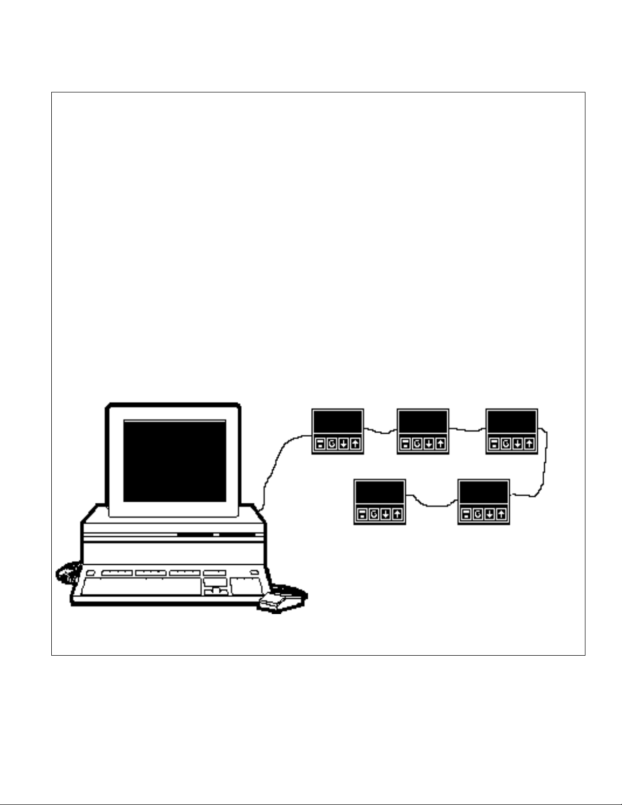
instruments communicate using a master-slave technique, in which only one device is the master and the
slave devices supply the requested data when addressed. Typical master devices can be a host computer, or
PLC (programmable logic controller), or a VersaChart.
MODBUS MESSAGE FRAMING
There are two serial transmission modes for the MODBUS protocol, ASCII or RTU (Remote Transmission
Unit) framing. The instruments use the RTU framing method only. The MODBUS message is placed into a
frame that has a known beginning and ending point by the transmitting device. This allows receiving devices
to begin at the start of the message, read the address portion and determine which device is addressed, and
know when the message is completed. Partial messages can be detected and errors can be set as a result.
RTU FRAMING
In RTU framing mode, the message starts with a silent interval of at least 3.5 character times. This is most
easily implemented as a multiple of character times at the baud rate that is going to be used in the network.
The first field then transmitted is the device address. Binary data is used for transmission for all fields.
Network devices monitor the network bus continuously, including the “silent” interval. When the first field is
received, each device decodes it to find out if it is being addressed.
Following the last transmitted character, a similar ‘silent’ interval of at least 3.5 character times marks the end
of the message. A new message can then begin after this interval. The entire message frame must be
transmitted as a continuous stream. If a ‘silent’ interval of more than 1.5 character times occurs before
completion of the frame, the receiving device discards the incomplete message and assumes the next byte
will be the address field of a new message.
If a new message begins earlier than 3.5 character times following a previous message, the receiving device
will consider it a continuation of the previous message. This will cause an error, as the value in the final CRC
field will not be valid for the combined messages. A typical message frame is shown below.
START ADDRESS FUNCTION DATA CRC CHECK END
T1-T2-T3-T4 8 BITS 8 BITS n X 8 BITS 16 BITS T1-T2-T3-T4
Note: All bytes are a total of 11 bits long, which include 1 start bit, 8 data bits, 1 parity
bit (if used), and 1 or 2 stop bits (depends if a parity bit is used).
MODBUS RTU PROTOCOL MANUAL
4
Page 5

RTU MODE
The main advantage of the RTU mode is that its greater character density allows better data throughput than
ASCII for the same baud rate. Each message must be transmitted in a continuous stream.
The format for each byte in RTU mode is:
Coding System: 8-bit binary
Bits per Byte: 1 start bit
8 data bits, least significant bit sent first
1 bit for even/odd parity; no bit for no parity
1 stop bit if parity is used; 2 bits if no parity
Baud Rate: 1200, 2400, 4800, and 9600
Error Check Field: Cyclical Redundancy Check (CRC)
CONTENTS OF THE DATA FIELD
The data field of messages sent from a master to a slave device contains additional information which the
slave must use to take the action defined by the function code. This can include items like register
addresses, the quantity of items to be handled, and the count of actual data bytes in the field.
For example, if the master requests a slave to read a group of holding registers (function code 03), the data
field specifies the starting register and how many registers are to be read. If the master writes to a group of
registers in the slave (function code 16), the data field specifies the starting register, how many registers to
write, the count of data bytes to follow in the data field, and the data to be written in the registers. If no error
occurs, the data field of a response from a slave to a master contains the data requested. If an error occurs,
the field contains an exception code that the master application can use to determine the next action to be
taken.
MODBUS RTU PROTOCOL MANUAL
5
Page 6

SECTION 2.0 - MODBUS FUNCTIONS SUPPORTED
The following is a list the functions to be supported. The JBUS names are listed first, where such an
equivalence exists, as these more closely represent the actual operations. The original Gould MODBUS
function names are listed for reference. The MODBUS Function number follows the names. In some cases
two function numbers will be supported, as they could be used interchangeably with respect to our unit.
JBUS MODBUS FUNCTION NUMBER
A Read n Bits Read Coil Status 01
Read Input Status 02
B Read n Words Read Holding Registers 03
Read Input Registers 04
C Write 1 Bit Force Single Coil 05
D Write 1 Word Preset Single Register 06
E Loopback Test Loopback Diagnostic Test 08
F Write n Words Preset Multiple Registers 16
The instrument will identify itself in reply to a Read Holding Register message which
inquires the value of parameter 121 & 122, as specified in the CNOMO documentation,
and the Modbus Function 17 ( Report Slave ID) will not be supported.
MODBUS RTU PROTOCOL MANUAL
6
Page 7

SECTION 3.0 - MESSAGE FORMATS
The first character of each message is an instrument address. The valid address range can be 0 to 247. The
second character is always the function number. The content remainder of the message depends upon the
function number. The maximum length of a message is 256 bytes.
In most cases the instrument is required to reply by echoing the address and function number, an echo of all
or part of the message received (in the case of a request to write a value or carry out a command) or the
information requested (in the case of a read parameter operation). Broadcast Messages (to which the
instrument responds by taking some action without sending back a reply) are supported at instrument address
zero. Commands that can be broadcast are so noted.
A message is terminated solely by a delay of at least 3.5 character lengths at the given baud rate, and any
character received after such a delay is treated as a potential address at the start of a new message.
Since only the RTU form of the protocol is being supported, each message contains binary data values and is
followed by a two-byte CRC16. This is a 16-bit cyclic redundancy checksum. There are two ways to get the
CRC values. One is calculated in accordance with a formula that involves recursive division of the data by a
polynomial, with the input to each division being the remainder of the results of the previous one. The other is
for you to use a CRC16 look-up table that is referenced in the Modicon Modbus Protocol Reference Guide.
More information on how the checksum must be calculated can be found in PI-MBUS-300 document at
Modicon's web address http//www.modicon.com
The following abbreviations or designations are used in specifying the message formats:
IA Instrument Address
FN Function Number
PCH Parameter Code High
PCL Parameter Code Low
NBH Number of Bits High
NBL Number of Bits Low
NWH Number of Words High
NWL Number of Words Low
COUNT Number of bytes of data
CRCH CRC16 - Cyclic Redundancy Check Value High
CRCL CRC16 - Cyclic Redundancy Check Value Low
In depicting message formats, parenthesis are used to represent a byte of data. The general format of the
message sent to the instrument will consist of 8 or more bytes, consisting of a "standard preamble" (IA and
FN bytes), data (dependent on the function), and a CRC16 as follows:
(IA) (FN) (data) (data) (data) (data) . . . . . . (CRCL) (CRCH)
The MODBUS documentation refers to a Starting Address as the pointer to Coil or Input Bits, or Holding or
Input Registers. They will be referred to as Parameter Codes in this document.
3.1 Read n Bits - Function Number 01/02
The message sent to the instrument will consist of 8 bytes consisting of the standard preamble, followed by
the parameter code of the first data bit to be read, and the two-byte bit count to be read, as follows:
(IA) (1 or 2) (PCH) (PCL) (NBH) (NBL) (CRCL) (CRCH)
The normal reply will echo the first 2 characters of the message received, and will then contain a single-byte
data byte count, which will not include itself or the CRC. For this message, there will be one byte of data per
eight bits-worth of information requested, with the LSB of the first data byte transmitted depicting the state of
the lowest-numbered bit parameter required.
(IA) (FN) (COUNT) (8 bits) (8 bits) (etc.) . . . (last 8 bits) (CRCL) (CRCH)
MODBUS RTU PROTOCOL MANUAL
7
Page 8

This function will be used to report instrument status information, such as local/remote or auto/manual status,
and so a bit set to 1 indicates that the corresponding feature is currently enabled/active/true, and a bit reset to
0 indicates the opposite. If an exact multiple of eight bits is not requested, the data is padded with trailing
zeros to preserve the 8-bit format.
3.2 Read n Words - Function Number 03/04
The message sent to the instrument will consist of 8 bytes consisting of the standard preamble, followed by
the parameter code of the first parameter to be read, and the two-byte word count to be read, as follows:
(IA) (3 or 4) (PCH) (PCL) (NWH) (NWL) (CRCL) (CRCH)
The reply sent by the instrument echoes the first two characters received and then contains a single-byte data
byte count, the value of which does not include either itself or the CRC value to be sent. For this message,
the count equals the number of words read times two. Following the byte count, the number of bytes are
transmitted, MSB first, followed by the CRC16.
(IA) (FN) (COUNT) (HI) (LO) (HI) (LO) (etc.) (etc.). . . (last HI) (last LO) (CRCL) (CRCH)
3.3 Write 1 Bit - Function Number 05
The message sent to the instrument will consist of 8 bytes consisting of the standard preamble, followed by
the parameter code of the bit to set and a two-byte word whose MSB contains the desired truth value of the
bit, expressed as 0xFF (TRUE) or 0x00 (FALSE), as follows:
(IA) (5) (PCH) (PCL) (State) (0) (CRCL) (CRCH)
Generally, this function will be used to control such features as auto/manual. The normal reply sent by the
instrument will be a byte-for-byte echo of the message received.
(IA) (5) (PCH) (PCL) (State) (0) (CRCL) (CRCH)
3.4 Write 1 Word - Function Number 06
The message sent to the instrument will consist of 8 bytes consisting of the standard preamble, followed by
the parameter code of the parameter to be written, and the two-byte value to which the parameter will be set,
as follows:
(IA) (6) (PCH) (PCL) (Value HI) (Value LO) (CRCL) (CRCH)
The normal response is to echo the message in its entirety.
(IA) (6) (PCH) (PCL) (Value HI) (Value LO) (CRCL) (CRCH)
3.5 Write n Words - Function Number 16
The message sent to the instrument will consist of 11 or more bytes consisting of the standard preamble.
Followed by the parameter code of the first parameter to be written, a two-byte word count, a one-byte byte
COUNT, and the series of two-byte words to which the parameters will be set. * See NOTE at Section 4.3
Multiple Parameter Value Communications, page 10.
(IA) (16) (PCH) (PCL) (NWH) (NWL) (COUNT) (Word HI) (Word LO)
(Word HI) (Word LO) . . . . . (Word HI) (Word LO) (CRCL) (CRCH)
The instrument normally responds with a 8 byte reply, as follows:
(IA) (16) (PCH) (PCL) (NWH) (NWL) (CRCL) (CRCH)
3.6 Loopback Diagnostic Test - Function Number 08
The message sent to the instrument will consist of 8 bytes consisting of the standard preamble, followed by a
four bytes of zeros, as follows:
MODBUS RTU PROTOCOL MANUAL
8
Page 9

(IA) (8) (0) (0) (0) (0) (CRCL) (CRCH)
Full MODBUS support in this area is not appropriate - consequently, the diagnostic code supported is code
0000. In response to the message the instrument must echo the
message received exactly.
3.7 Error and Exception Responses
If the instrument receives a message which contains a corrupted character (parity check fail, framing error.
etc.), or if the CRC16 check fails, the instrument ignores the message. If the message is otherwise
syntactically flawed (e.g. the byte count or word count is incorrect) the instrument will also not reply.
If the instrument receives a syntactically correct message which contains an illegal value, it will send an
exception response, consisting of five bytes as follows:
(IA) (FN) (Exception Number) (CRCL) (CRCH)
The Function Number field consists of the function number contained in the message which caused the error,
with its most significant bit set (i.e. function 6 becomes x86), and the Exception Number is one of the codes
contained in the following table:
Code Name Cause
1 ILLEGAL FUNCTION Function number out of range
2 ILLEGAL DATA ADDRESS Parameter ID out of range or not supported
3 ILLEGAL DATA VALUE Attempt to write invalid data or not enough data words
4 DEVICE FAILURE N/A
5 ACKNOWLEDGE N/A
6 BUSY N/A
7 NEGATIVE ACKNOWLEDGE N/A
MODBUS RTU PROTOCOL MANUAL
9
Page 10

SECTION 4.0 - PARAMETER VALUE COMMUNICATIONS
There are three different types of parameter values, Bit parameter, Single parameter, and Multiple parameter
values.
4.1 Bit Parameter Communications
The bit parameters are fairly straight forward. The bits are accessed and transmitted per the protocol while
they are stored in the instrument as one-byte entities.
The computer can read single or multiple bits using Function Numbers 01 or 02. The computer can write a
single bit using Function Number 05. We do not support multiple bit writes via Function Number 15, as this
is seldom done in real world applications and MMI or SCADA programs don't always support it either.
4.2 Single Parameter Value Communications
The two-byte integer values are straight forward. Values are stored, accessed, transmitted and treated simply
as two-byte or word oriented entities.
4.3 Multiple Parameter Value Communications
In addition to being able to read or write any one of the data types in a single operation, Function Numbers
03/04 or 16 can be used to read or write a series of consecutive registers that correspond to any mix of data
types, provided the number of consecutive registers falls on a parameter boundary. Otherwise, the
instrument will not accept the command and will respond with an Exception Code of 3, ILLEGAL DATA
VALUE. To simplify coding, the instruments will process data in order of occurrence, and only not
accept/process the command for the last parameter if it does not fall on the end of the parameter boundary.
*NOTE: Support for multi-parameter writes is limited to support of the Multi-word Write Function (Number
16), but will permit writing of one parameter only per message. The multi-parameter read function supports a
maximum of 10 parameters in one message.
MODBUS RTU PROTOCOL MANUAL
10
Page 11

SECTION 5.0 - READ & WRITE EXAMPLES
Read Example #1 : To read the process value from the instrument. Please note: you would use Modbus
Function 3 (Read n Words). Abbreviated in this example as (FN).
The message sent to “read from” the instrument’s at address #2 (IA) would be as follows:
[address of 1st word] [number of words] [CRC16]
(IA) (FN) (High byte) (Low byte) (NBH) (NBL) (CRCL) (CRCH)
Hex out: (02) (03) (00) (01) (00) (01) (D5) (F9)
The response if the process value is “79” :
(IA) (FN) (count) (1st Value) (Last Value) (CRCL) (CRCH)
Hex in: (02) (03) (02) (00) (4F) (BD) (BO)
Read Example #2 : Read the setpoint value (Word parameter 2) from the instrument. Please note: you
would use Modbus Function 3 (Read n Words). Abbreviated in the example as (FN).
The message sent to “read from” the instrument’s address 2 (IA) would be as follows:
[address of 1st word] [number of words] [CRC16]
(IA) (FN) (High byte) (Low byte) (NBH) (NBL) (CRCL) (CRCH)
Hex out: (02) (03) (00) (02) (00) (01) (25) (F9)
The response if the setpoint value is “200” :
(IA) (FN) (count) (1st Value) (Last Value) (CRCL) (CRCH)
Hex in: (02) (03) (02) (00) (C8) (FD) (D2)
MODBUS RTU PROTOCOL MANUAL
11
Page 12

Write Example #1: The message sent to write “450” to the instrument’s setpoint would be:
[address of 1st word] [value of 450] [CRC16]
(IA) (FN) (High byte) (Low byte) (Value Hi) (Value Lo) (CRCL) (CRCH)
Hex out: (02) (06) (00) (02) (01) (C2) (A8) (38)
The response if the setpoint value is changed to “450” and accepted is:
(IA) (FN) (High byte) (Low byte) (NBH) (NBL) (CRCL) (CRCH)
Hex in: (02) (06) (00) (02) (01) (C2) (A8) (38)
The instrument should respond by echoing the message.
If the instrument did not accept the new setpoint value, say because of a setpoint limit or out range the
response would be:
(IA) (FN)* (Exception #) (CRCL) (CRCH)
Hex in: (02) (86) (03) (F2) (61)
*Note: See Error and Exception Response Section 3.7, page 9.
Write Example #2: The message sent to write a “1” to the instrument’s Auto/Manual
(Bit parameter 2) would be as follows:
[address of 1st word] [bit value = 1 or (FF)] [CRC16]
(IA) (FN)* (High byte) (Low byte) (State) (0) (CRCL) (CRCH)
Hex out: (02) (05) (00) (02) (FF) (00) (2D) (C9)
*Note: See Function 5 (Write 1 Bit) for this example. See Section 3.3.
MODBUS RTU PROTOCOL MANUAL
12
Page 13

APPENDIX
NOTE: When using a third party MMI or SCADA software package please be aware that you may have to offset
each of the register addresses by adding one. This is because some packages are assuming that Modbus RTU is
communicating to a PLC (Programmable Logic Controller) which uses zero as the first legitimate register
assignment, while humans think of one as the first legitimate register address. Using Intellution’s “The FIX” MMI
software, the register assignments had to be offset by one. An example: To read the 1601’s Setpoint value, you
must use 00003, instead of word register 00002. To read the Process Variable you must use register 00002,
instead of word register 00001).
CN1601, 1611, 1621 Bit Parameters :
PARAMETER NO. NOTES
Communication Write Status 1 (R/O) (1 = if write enabled)
Auto / Manual 2 1 = Manual On
Self Tune 3 1 = Self Tune Active
Pretune* 4 1 = Pretune Active
Alarm 1 Status 5 (R/O) Set if Active
Alarm 2 Status 6 (R/O) Set if Active
Setpoint Ramp Enable(d) 7 1 = Enabled
Loop Alarm Status 10 1 = Enabled
*NOTE: To enable Pretune, write a non-zero value to that parameter; to disable Pretune, write a zero to that
parameter. Enable Pretune will fail if the process value is within 5% of input span from the setpoint. This failure will
not be indicated by communications. Please note this is for all units that have Pretune.
CN1601, 1611, 1621 Word Parameters:
PARAMETER NO. NOTES
Process Variable 1 R/O
Setpoint 2 Target if ramping
Output Power 3 R/O unless in Manual
Deviation 4 R/O
PB2 5 R/O if Self Tuning
PB1 6 R/O if Self Tuning
Direct / Reverse Acting 7 1 = Direct Acting, 0 = Reverse
Reset (or Loop Alarm Time) 8 R/O if Self Tuning
Rate 9 R/O if Self Tuning
Output 1 Cycle Time 10
Scale Range Low 11 Linear Inputs only
Scale Range High 12 Linear Inputs only
Alarm 1 Value 13
Alarm 2 Value 14
Manual Reset 15
Overlap / Deadband 16
On / Off Differential 17
Decimal Point Position 18 Linear Inputs only
Output 2 Cycle Time 19
Output 1 Power Limit 20
Internal Setpoint 21 R/O - current value
Setpoint High 22
Setpoint Low 23
Setpoint Ramp Rate 24
Filter Time Constant 25
Process Value Offset 26
Recorder output Max 27
CN1601, 1611, 1621 Word Parameters:
MODBUS RTU PROTOCOL MANUAL
13
Page 14

PARAMETER NO. NOTES
Recorder Output Min 28
Manufacturer ID* 121 R/O
Equipment ID* 122 R/O
*NOTE: Some of the parameters which do not apply to a particular instrument configuration (e.g. PB2 on a single
output zone) will accept reads and writes. Others will accept read only, and will return an exception if an attempt is
made to write values to them.
CN1602, 1612, 1622 Bit Parameters:
PARAMETER NO. NOTES
Communication Write Status 1 (R/O) (1 = if write enabled)
Limit Action 2 (R/O) (1 = Low Limit)
Reset Limit Controller 3 (W/O) (write 1 to reset) Always reads 0
Limit Status 4 (R/O) (1 = exceeded )
Alarm 1 Status 5 (R/O) (1 = if Active)
Alarm 2 Status 6 (R/O) (1 = if Active)
Limit Output Status 7 (R/O) (1 = if Active)
Annunciator Output Status 8 (R/O) (1 = if Active)
CN1602, 1612, 1622 Word Parameters:
PARAMETER NO. NOTES
Process Variable 1 R/O
Limit Setpoint 2
Min/Max Hold 3 Write any value resets *
Deviation 4 R/O
Time Lapsed 5 Write any value resets *
Limit Hysteresis 6
Alarm 1 Value 7
Alarm 2 Value 8
Range Low 9 R/O on non-linears
Range High 10 R/O on non-linears
Decimal Point Position 11 R/O on non-linears
Filter Time Constant 12
Recorder O/P Max 13 if Recorder O/P configured
Recorder O/P Min 14 if Recorder O/P configured
Manufacturer ID 121 R/O - 231, representing “W1”
Equipment ID 122 R/O - number 6702
*NOTES: When the process value is in the over range, under range or sensor break condition the values
returned will be as follows:
over range 12288
under range 63488
sensor break 32512
The max/min hold value will also return 32512 if the process value has seen sensor break condition since the last
reset.
The time exceeded parameter will return the over range value (12288) if the time becomes greater than 1000
minutes.
MODBUS RTU PROTOCOL MANUAL
14
Page 15

DP1610 Bit Parameters:
PARAMETER NO. NOTES
Alarm 1 Status 1 (R/O) (1 = if active)
Alarm 2 Status 2 (R/O) (1 = if active)
Alarm 3 Status 3 (R/O) (1 = if active)
Alarm 1 Latching 4 (R/O) (1 = if alarm is set to be latching )
PV Over Range Flag 5 (R/O) (1 = if Active)
PV Under Range Flag 6 (R/O) (1 = if Active)
Sensor Break active 7 (R/O) (1 = if Active)
Reset Latched Alarm 8 (W/O)
Reset Max 9 (W/O)
Reset Min 10 (W/O)
Reset Time Elapsed 11 (W/O)
DP1610 Word Parameters:
PARAMETER NO. NOTES
Process Variable 1 R/O
PV Max 2 R/O
PV Min 3 R/O
Time Elapsed 4 R/O
Status 5 R/O
PV Offset 6
Alarm 1 Value 7
Alarm 2 Value 8 if alarm 2 configured
Alarm 3 Value 9 if alarm 3 configured
Alarm 1 Hysteresis 10
Alarm 2 Hysteresis 11 if alarm 2 configured
Alarm 3 Hysteresis 12 if alarm 3 configured
Filter Time Constant 13
Decimal Point Position 14 R/O on non-linears
Range Low 15 R/O on non-linears
Range High 16 R/O on non-linears
Recorder O/P Min 17 if Recorder O/P configured
Recorder O/P Max 18 if Recorder O/P configured
Manufacturer ID 121 R/O - 231, representing “W1”
Equipment ID 122 R/O - number 8010
DP/CN1632 Bit Parameters :
PARAMETER NO. NOTES
Reserved 1
Reserved 2
Reserved 3
Pretune* 4 1 = Pretune Active
Alarm 1 Status 5 (R/O)
Alarm 2 Status 6 (R/O)
Reserved 7
*NOTE: To enable Pretune, write a non-zero value to that parameter; to disable Pretune, write a zero to that
parameter. Enable Pretune will fail if the process value is within 5% of input span from the setpoint. This failure will
not be indicated by communications.
DP/CN1632 Word Parameters:
MODBUS RTU PROTOCOL MANUAL
15
Page 16

PARAMETER NO. NOTES
Process Variable 1 R/O
Current Setpoint Value 2 R/O
Output Power 3 R/O
Deviation 4 R/O
Proportional Band 5 R/O if EZTune
Reset 6 R/O if EZTune
Rate 7 R/O if EZTune
Bias 8
ON/OFF Differential 9
Output 1 Cycle Time 10
Filter Time Constant 11
Alarm 1 Value
Alarm 2 Value 13
Selected Setpoint (1 or 2) 14
Setpoint 1 Value 15
Setpoint 2 Value 16
Process Variable Offset 17
Decimal Point Position 18 Linear Inputs only
Manufacturer ID* 121 R/O
Equipment ID* 122 R/O
NOTE: Manufacturer ID: Always returns a value of 231
Equipment ID : Returns model: 2300
MODBUS RTU PROTOCOL MANUAL
16
 Loading...