

Page 1
TM
User’s Guide
Shop online at
omega.com
e-mail: [email protected]
For latest product manuals:
www.omegamanual.info
SM
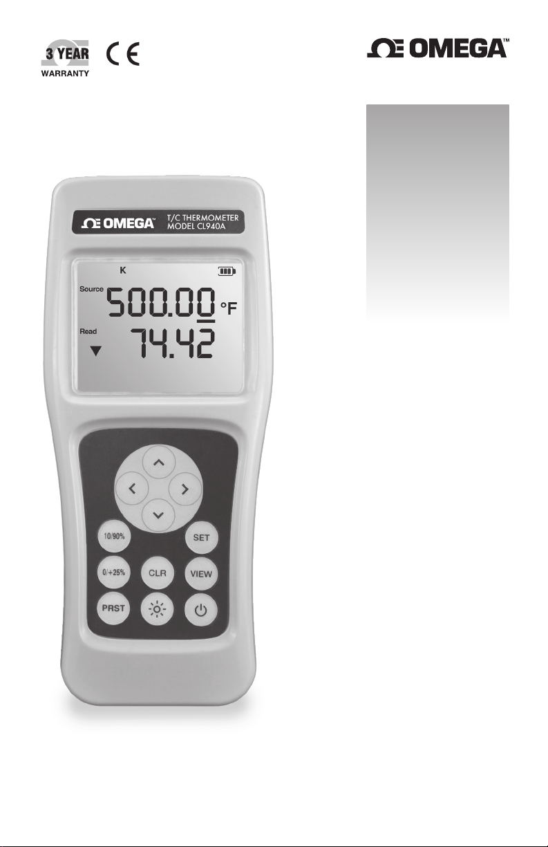
CL940A, CL945A
Digital Temperature
Calibrator–Thermometer
Page 2

Where Do I Find Everything I Need
for Process Measurement and Control?
OMEGA… Of Course!
Shop online at omega.com
TEMPERATURE
MU
Thermocouple, RTD & Thermistor Probes, Connectors, Panels & Assemblies
MU
Wire: Thermocouple, RTD & Thermistor
MU
Calibrators & Ice Point References
MU
Recorders, Controllers & Process Monitors
MU
Infrared Pyrometers
PRESSURE, STRAIN AND FORCE
MU
Transducers & Strain Gages
MU
Load Cells & Pressure Gages
MU
Displacement Transducers
MU
Instrumentation & Accessories
FLOW/LEVEL
MU
Rotameters, Gas Mass Flowmeters & Flow Computers
MU
Air Velocity Indicators
MU
Turbine/Paddlewheel Systems
MU
Totalizers & Batch Controllers
pH/CONDUCTIVITY
MU
pH Electrodes, Testers & Accessories
MU
Benchtop/Laboratory Meters
MU
Controllers, Calibrators, Simulators & Pumps
MU
Industrial pH & Conductivity Equipment
SM
DATA ACQUISITION
MU Communications-Based Acquisition Systems
MU Data Logging Systems
MU Wireless Sensors, Transmitters, & Receivers
MU Signal Conditioners
MU Data Acquisition Software
HEATERS
MU
Heating Cable
MU
Cartridge & Strip Heaters
MU
Immersion & Band Heaters
MU
Flexible Heaters
MU
Laboratory Heaters
ENVIRONMENTAL
MONITORING AND CONTROL
MU
Metering & Control Instrumentation
MU
Refractometers
MU
Pumps & Tubing
MU
Air, Soil & Water Monitors
MU
Industrial Water & Wastewater Treatment
MU
pH, Conductivity & Dissolved Oxygen Instruments
M5725/0219CL940A Rev. A
Page 3
Table of Contents
TABLE OF CONTENTS
1. Instrument Description ............................................................. 1-1
Specifications .................................................................... 1-1
OMEGA Family of Thermometers ........................................... 1-5
2. Preparation for Use .................................................................. 2-1
General Information ........................................................... 2-1
Feature Overview ............................................................... 2-1
Safety Notices and Information ............................................ 2-2
Unpacking and Inspection .................................................... 2-4
Battery Installation and Replacement .................................... 2-4
Initial Power ON ................................................................. 2-5
3. Operating Instructions .............................................................. 3-1
Keypad Functions ............................................................... 3-1
LCD Display ....................................................................... 3-2
Setup Menu ....................................................................... 3-4
View Modes and Statistics .................................................... 3-6
Auto-Power Off .................................................................. 3-7
Backlight and Backlight Timeout ........................................... 3-8
Operating Modes ................................................................ 3-8
Trend Indicators ................................................................. 3-9
Battery Indicator ................................................................ 3-9
Probe Offset ...................................................................... 3-9
Open Lead Detection Enable/Disable ................................... 3-11
Clear Function .................................................................. 3-11
Presets: Save, Recall and Erase .......................................... 3-12
Invalid Measurement Indications ........................................ 3-13
4. Service Information ................................................................ 4-14
Inspection and Cleaning .................................................... 4-14
Calibration ...................................................................... 4-14
Troubleshooting ............................................................... 4-19
Diagnostic Routines and Error Codes ................................... 4-20
Memory Sterilization ......................................................... 4-20
Statement of Calibration .................................................... 4-21
A. Required Equipment .................................................................. A-i
B. Expanded Instrument Uncertainties ............................................. B-i
C. Instrument Verification Data Sheet .............................................. C-i
Page 4
Instrument Description
1. INSTRUMENT DESCRIPTION
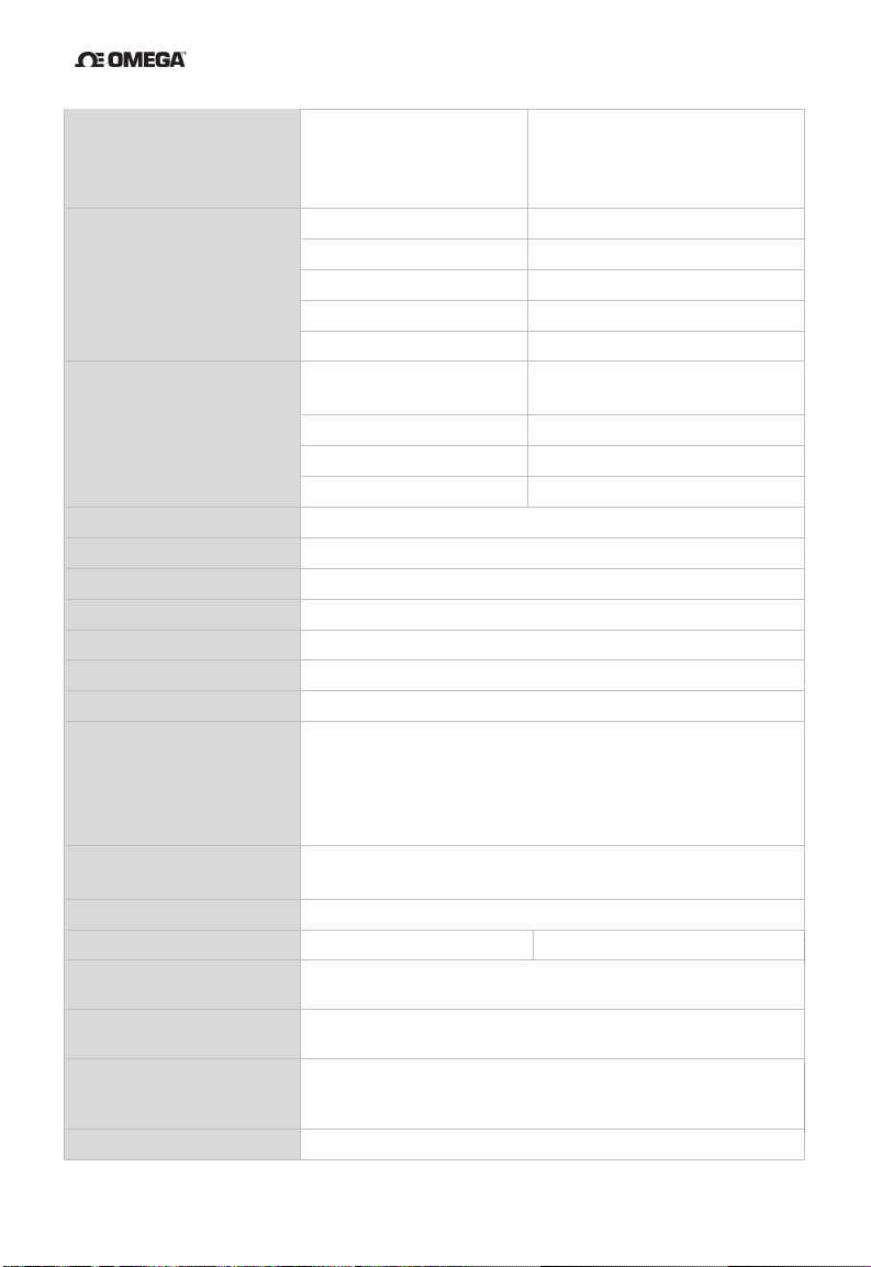
Source/Measure
R
0.01°C
999.99°C
0.1°C ≥ 1000°C
R
-15MV
V
C
±0.15°C
5-D
(0.1/0.01)
A
28°C (64.4
82.4°F) | CJC error included
ITS-90
Types B,E,J,K,N,R,S,T
DIN 43710
Types L and U
ASTM E1751 5.1.2
Type P
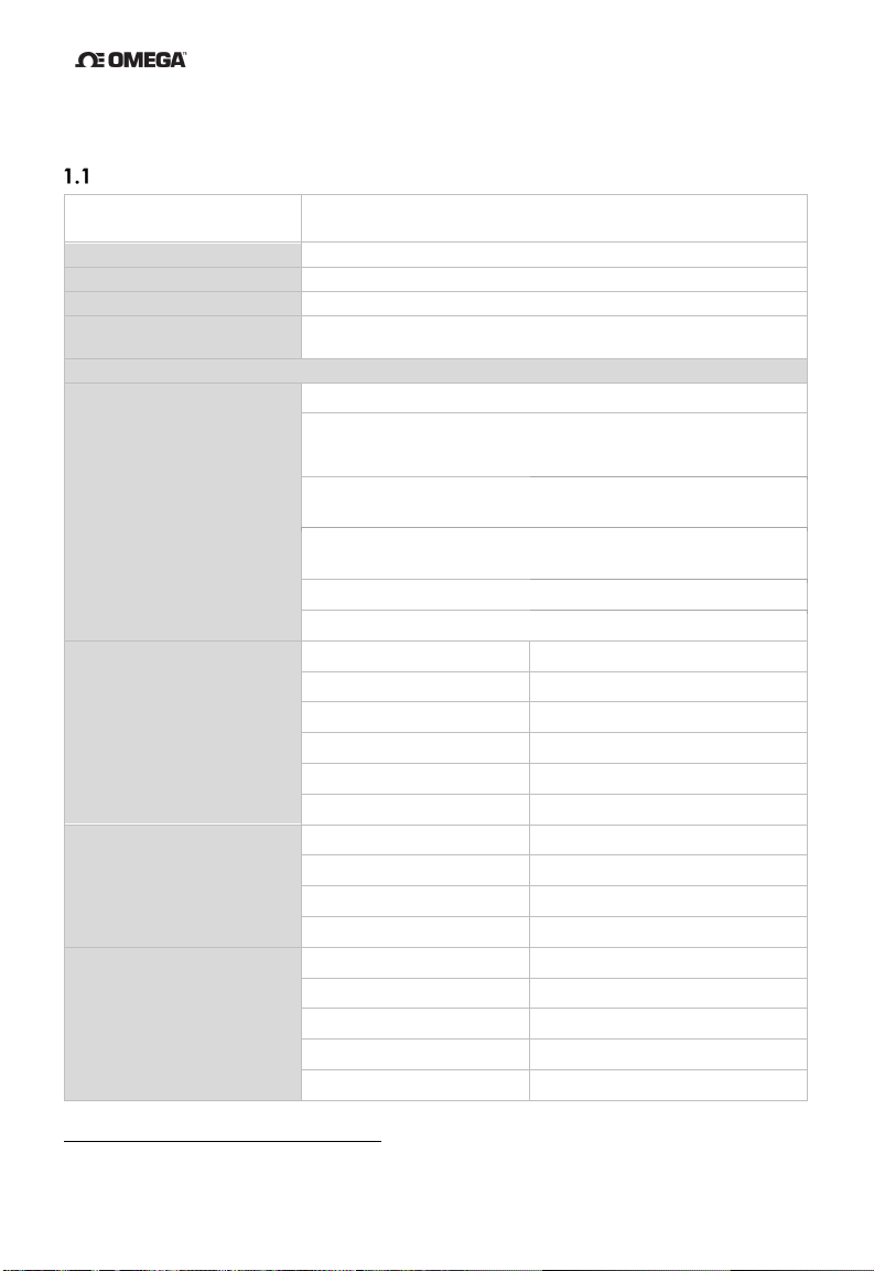
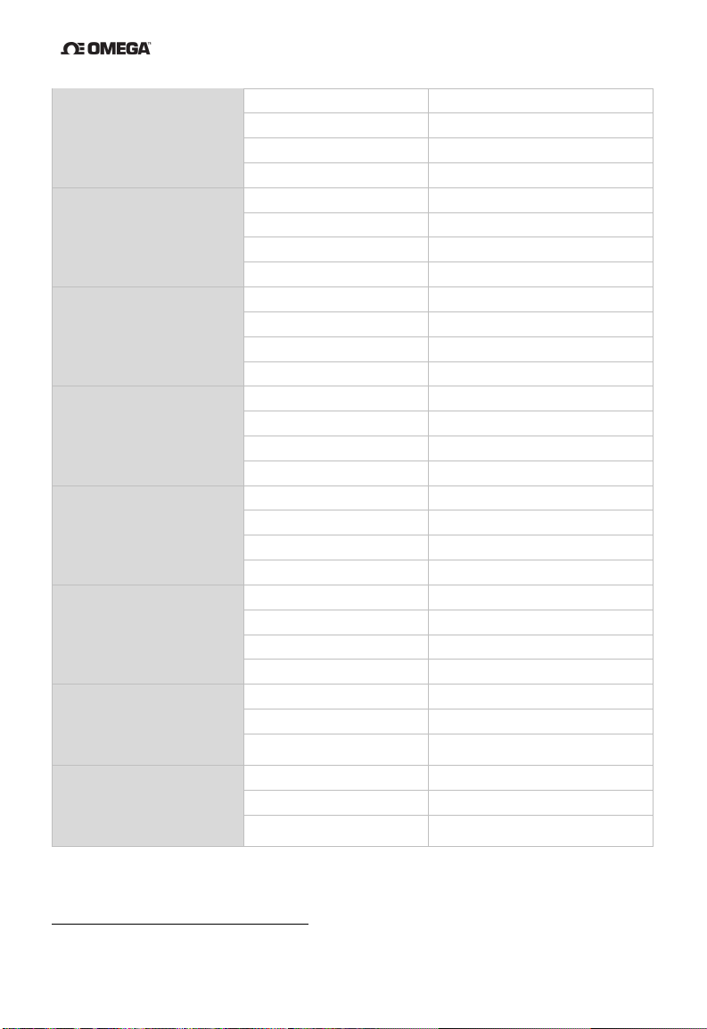
Temperature Ranges
°C Range
°C
-230 to -160
±1.2 to ±0.6
-160 to -90
±0.5 to ±0.4
-90 to 380
±0.3
380 to 665
±0.2
665 to 1372
±0.3
-200 to -160
±0.7 to ±0.5
-160 to -110
±0.4
-110 to 10
±0.3
10 to 1200
±0.2
-260 to -190
±2.6 to ±0.7
-190 to -120
±0.6 to ±0.5
-120 to -70
±0.4
-70 to 80
±0.3
80 to 400
±0.2
Specifications
Accuracy
ESOLUTION
ANGE
OLD JUNCTION ERROR
DISPLAY
CCURACY1 OVER RANGE OF 18 TO
±0.003% * [READ ING] ± 5µV 18° TO 28°C
FUNCTION
EN 60584-1 2013 Type C
UP TO
TO 85M
IGIT AUTO-RESOLUTION
ANNUNCIATORS
TO
AND
1
WITH BACKLIGHT AND
Conformity
K
-230°C - 1372°C
-382°F - 2502°F
J
-200°C - 1200°C
-328°F – 2192°F
T
-260°C – 400°C
-436°F – 752°F
ASTM E988 Table 3 Type D
ASTM E1751 5.1.1 Type G
1
See Graphs in Appendix B for Expanded Uncertainties
1-1
Page 5
Instrument Description
E
-240 to -150
±1.2 to ±0.4
-150 to -100
±0.4
-100 to 20
±0.3
20 to 1000
±0.2
310 to 595
±1.8 to ±1.0
595 to 830
±0.9
830 to 965
±0.7
965 to 1820
±0.6
-230 to -150
±1.6 to ±0.7
-150 to -50
±0.5
-50 to 215
±0.3
215 to 1300
±0.2
-15 to 100
±1.2 to ±0.8
100 to 240
±0.7
240 to 495
±0.6
495 to 1768
±0.5
-20 to 75
±1.2 to ±0.9
75 to 150
±0.8
150 to 285
±0.7
285 to 1768
±0.6
100 to 240
±1.0 to ±0.6
240 to 310
±0.5
310 to 460
±0.4
460 to 2315
±0.3
C2
0 to 60
±0.5
60 to 2200
±0.4
D2
0 to 100
±0.6 to ±0.5
100 to 230
±0.4
-240°C – 1000°C
-400°F – 1832°F
2
B
310°C – 1820°C
590°F – 3308°F
N2
-230°C – 1300°C
-382°F – 2372°F
R2
-15°C – 1768°C
5°F – 3214°F
S2
-20°C – 1768°C
-4°F – 3214°F
G2
100°C - 2315°C
212°F – 4199°F
0°C – 2315°C
32°F – 4199°F
2200 to 2315 ±0.5
0°C – 2315°C
32°F – 4199°F
230 to 2315 ±0.3
2
Thermocouple types B, N, R, S, C, D, G, P, L and U are model CL945A only.
1-2
Page 6
Instrument Description
P2
0°C to 1395°C
-200 to -90
±0.6 to ±0.4
-100 to -40
±0.4
-40 to 655
±0.3
655 to 665
±0.4
665 to 900
±0.3
-75 to 0
±0.4
-0 to 385
±0.3
385 to 600
±0.2
Connector Type
Two (2) Mini-TC Copper
Temperature Units
°C, °F, mV
Probe Zero Function
Resolution 0.1 °C/°F
Reading Rate
3/sec. for Readings and TREND indicators
Battery Type
3 AA (IEC LR6, ANSI 15) Alkaline
Battery Life
500 Hours Typical
Battery Indicator
Four (4) Stage Battery Charge Indicator
Two (2) rows of Five (5) digit LCD with separate minus
Minimum Reading, Maximum Reading, Average Reading,
Display Backlight
Four (4) LED Backlight with 30-second timeout
Display Resolution
0.01° <1000 °
.1° ≥ 1000 °
20 minute no key pressed Auto Off. Feature can be
Twelve (12) momentary switches with audible and tactile
Power Cycle
Instrument retains: Sensor Type, Temperature Unit
Internal Preset Storage
20 Preset user-determined storage registers, 0-19
32°F to 2543°F
L2
J-DIN
-200°C - 900°C
-328°F – 1652°F
0 to 1395 ±0.3
U2
T-DIN
-200°C – 600°C
-328°F – 1112°F
Display
Statistics
Auto Off
-200 to -75
sign, decimal indicators, with offset, thermocouple types
KJTEBNRSGCDPLU, battery, source, read, temperature
units, voltage units, percent, trend, PRST (0-19), MIN,
MAX, AVG, RNG, STDEV, Transfer, symbols: Fast Ramp,
Slow Ramp, Step, Bluetooth
Reading Range, Standard Deviation
disabled
±0.8 to ±0.5
Keypad
Configuration
Retention
feedback
Offset Values, Presets, Statistics, Open Lead detection
status, 0%/100% span settings, and operating mode
1-3
Page 7

Instrument Description
Input Current
±50 nA maximum
Maximum Common
Mode Voltage
Low Resistance Load
Less than 5µV change in output with a 100KΩ resistance
Operating
Operating Temp
-20 to 55 °C
-4 to 131 °F
Storage Temp
-51 to 71 °C
-59.8 to 159.8 °F
<10 °C (50 °F): Non-condensing
Altitude
0 to 4600 m
0 to 15,092 ft
Vibration
Random 10 – 500 Hz, 0.03 g2/Hz
Shock
30g Half Sine
Drop
4 Drops from 1 m to Concrete
Compliance, Electrical
CE, MIL-PRF-28800F Class 2
Compliance,
Electrical Safety
IEC-61010
EMC
EN 61326, MIL-PRF-28800F, Class 2
ESD
IEC 61326 Criterion B
Sanitation
NSF/ANSI/3-1 14159-2
Standards
MIL-PRF-28800F, Class 2
For specification variances due to ambient operating temperature,
3 AA Batteries, Quick Start Guide, Tilt Stand/Magnetic,
P
Dimensions
193 x 84 x 28 mm
7.6 x 3.3 x 1.1 in
Weight including
Environment
42 V peak to earth 1 V p-p between T1 and T2
Humidity
Substances
Temperature
Coefficient
Included Accessories
HYSICAL
CHARACTERISTICS:
10 to 30 °C (50 to 86 °F): 5 to 95% RH
30 to 40 °C (86 to 104 °F): 5 to 85% RH
40°C to 55°C (104 to 131 °F): 5 to 60% RH
RoHS 2 Directive, 2011/65/EU Compliant, REACH
see the Expanded Instrument Uncertainty charts in Appendix B of
this manual. For ambient operating temperatures not shown in
Appendix B, accuracies shall be interpolated linearly.
Calibration Report
Batteries
362.9g 12.8 oz.
1-4
Page 8

Instrument Description
OMEGA Family of Thermometers
Thermocouple Thermometer, Single Input
Thermocouple Thermometer, Dual Input
Data Thermometer, Single Input
Data Thermometer, Dual Input
Thermocouple
Thermometers
Data
Thermometers
HH911T
HH912T
HH931T
HH932T
1-5
Page 9

Preparation for Use
2. PREPARATION FOR USE
General Information
This manual provides operating instructions and maintenance information for two calibrator
instruments, CL940A and CL945A. These instruments are high performance calibratorthermometers capable of simulating and measuring a wide-variety of sensors. In addition,
features such as high accuracies, preset storage, ramp, step and transfer modes further
enhance their versatility.
It is recommended that you read this manual thoroughly, especially the sections on safety,
prior to operating these instruments.
Feature Overview
• 0.01° / 0.1 ° display resolution
• Internal storage for 20 presets
• 500-hour battery life
• Five (5) digit dual LCD with LED Backlight
• Simultaneous Source/Measure
• Comprehensive real-time statistics: MIN, MAX, AVG, RNG, and STDEV
• Easy to clean
• Probe offset function to minimize probe error
• °F, °C, and mV temperature and voltage units
• Durable: Meets MIL-PRF-28800F, Class 2 requirements
• Tilt Stand/Magnet/Hanger
3
3
Typical battery life under normal use conditions in laboratory environment. Continuous or repeated use of
features such as the backlight or use or storage at high or low temperature extremes may reduce battery life.
2-1
Page 10

Preparation for Use
SO.
could expose users to elevated potentials.
Never use this instrument or any temperature probe or sensor inside a microwave oven.
damage or personal injury could result from exceeding a probe’s maximum temperature rating.
Safety Notices and Information
Read this Operation Manual thoroughly before using the instrument to become familiar with its
Visually inspect instrument before using. Do not use if unit appears damaged or with any part of the
MAINTENANCE INSTRUCTIONS WITHIN THIS MANUAL ARE FOR USE BY QUALIFIED SERVICE
PERSONNEL ONLY. DO NOT ATTEMPT TO SERVICE THIS UNIT UNLESS YOU ARE QUALIFIED TO DO
Disconnect all temperature probes and turn the unit off before removing the battery cover.
Never connect thermocouple leads to any source where more than 42 Volts (peak) could exist
between the lead and ground. If it is necessary to make measurements of an object at elevated
electrical potential, the user is responsible for obtaining and properly using a probe that provides
adequate insulation between the surface with elevated potential and the thermocouple wiring.
Always disconnect probe leads before opening the battery door or the instrument housing.
Internal circuits can present a shock hazard if leads are connected to a source of elevated potential.
Do not use this instrument if the housing, probe wiring, probe, or probe handle are damaged
or distorted. Housings and wire insulation are part of the personnel protection system, and if damaged
Never use or store this product with batteries installed, or change batteries, in an
environment where explosive or flammable vapors or dust suspensions may exist. For
thermocouple thermometers suitable for use in explosive environments, see Error! Reference source
not found.’s 921A or 922A Intrinsically Safe Thermometers.
Do not attempt to recharge alkaline batteries.
Do not put batteries into bags designed to protect parts from electrostatic discharge (ESD).
These bags are specially designed with metal shielding which can short circuit a battery.
Do not expose batteries to extreme heat or fire. Observe all regional laws and regulations when
disposing batteries.
operations and capabilities.
case removed.
WARNING
SHOCK HAZARD
EXPLOSION HAZARD
BURN HAZARD
Do not touch a temperature probe sheath that has been exposed to toxic substances or
extremely high or low temperatures.
Do not attempt to measure temperatures beyond the range of the temperature probe. Probe
Safety Notices and Information continued on next page . . . .
2-2
Page 11

Preparation for Use
RISK OF INSTRUMENT DAMAGE
care to avoid static discharge when handling the instrument or connected probes.
Do not use when AC or DC voltages in excess of 1V exist between thermocouple channels (on
instruments with more than one channel). Excessive voltage could result in an incorrect reading,
or in more extreme cases, a blown fuse that will result in incorrect readings and need for repair.
Only replace batteries with size AA (IEC LR6, ANSI 15). Observe proper polarity when installing
batteries. Do not mix old and new batteries.
Do not apply voltages across thermocouple leads in excess of normal thermocouple voltage
for the selected range. Excessive input voltage could result in blown fuse, component damage, or
fire. Application of excessive voltage is not covered by the warranty.
Avoid making sharp bends in probe or sensor lead wires. Bending lead wires at sharp angles can
damage the wire and cause probe failure.
When using both thermometer inputs and a voltage differential exists between the two
measurement points, at least one probe should be electrically insulated. If not, a ground-loop
current can flow through the thermocouple leads causing measurement error or instrument damage.
Static discharge through a connected temperature probe may cause instrument damage. Use
RISK OF INCORRECT READING
CAUTION
2-3
Page 12
Preparation for Use
Always turn the instrument off and disconnect any input connections before replacing
instrument.
to the instrument.
Unpacking and Inspection
Each instrument is electrically and mechanically inspected before shipment. Upon receiving
your new OMEGA Data Thermometer, unpack all items from the shipping container and
check for any obvious damage that may have occurred during transit. Use the original
packing materials if reshipment is necessary.
If any dents, broken, or loose parts are seen, do not use the equipment. Notify OMEGA
immediately.
Check that all items are present. If any items are missing, notify OMEGA immediately.
The following items are included with every new instrument:
• One (1) Calibrator Thermometer;
• One (1) Quick Start Guide;
• Calibration Report;
• Three (3) AA, 1.5 V batteries; and
• Optional accessories (if purchased).
Battery Installation and Replacement
Three (3) AA 1.5 V batteries are supplied with the instrument, but not installed. Read the
following battery replacement instructions before attempting to install or remove the
batteries.
CAUTION
CAUTION
CAUTION
the batteries. Re-install the battery compartment cover before resuming use of the
The battery compartment is sealed with a rubber gasket. Use care to not damage the
gasket when removing or installing the battery compartment cover.
Remove the batteries when storing the instrument for an extended period of time or
in a high temperature environment to prevent battery leakage and possible damage
All measurement parameters may be reset to factory default if batteries are removed while
the instrument is powered on. Always turn the instrument off before changing batteries.
To install or replace batteries:
Required Tools: Phillips Head Screwdriver
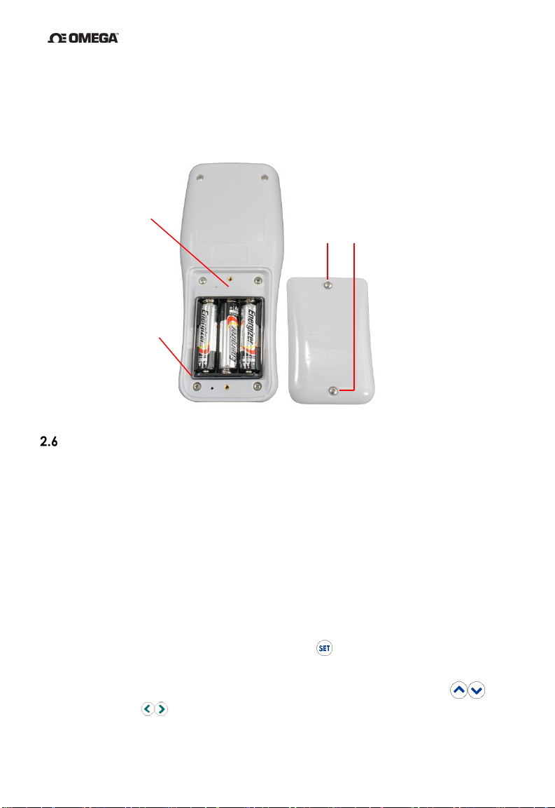
1. Identify the battery compartment located on the back of the instrument (see
Figure 1 below);
2. Remove the two (2) battery compartment retaining screws;
3. Remove the battery compartment cover;
4. If present, carefully remove old batteries being careful to not damage the battery
contacts;
2-4
Page 13
Preparation for Use
Retaining
Screws
Battery
Gasket
5. Observing proper polarity, install three (3) new, AA alkaline (IEC LR6, ANSI 15)
batteries;
6. Re-install the battery cover and two (2) retaining screws;
7. At initial power on after battery replacement, allow approximately 30 seconds for
instrument to stabilize.
Compartment
Figure 1: Battery Installation
Initial Power ON
OMEGA’s 900 Series Calibrator Thermometers are designed for easy operation, while still
providing a feature-rich experience via the intuitive user interface.
To get started follow these steps:
1. Perform Section 2.5, Battery Installation and Replacement;
2. The instrument will initially display every segment on the LCD for 2 seconds as a
test. An internal hardware, memory and battery self-test is performed during this
time.
3. Upon completing the internal tests, the instrument will immediately display the
Source and Read mode last user settings and battery indicator.
4. Set the desired measurement parameters as follows:
a. Enter the Setup Menu by pressing , hold the key down for
approximately 1.5 seconds, and then release it;
b. The active thermocouple type is flashing on the display. Use or
to select the desired thermocouple type. You are setting the
thermocouple type of the Read Channel.;
2-5
Page 14

Preparation for Use
desired digit or changing the mode.
The arrows always change a value. The arrows position
the cursor or will act to select only when changing Thermocouple type,
c. Momentarily (do not hold) press to save your selection and move to
the next parameter;
d. The active temperature unit is flashing on the display. Use to
select the desired temperature unit (°C, °F, or mV);
e. Momentarily press to save your selection and move to the next
parameter;
f. Read Channel 2 offset value is flashing on the display. If the
temperature probe’s offset value is known, press to set the
Channel 2 probe offset to the probe’s offset value. See Section 3.10,
Probe Offset, for more information.
g. Momentarily press to save your selection and move to Open Lead
Detection, press to toggle on/off;
h. Momentarily press to save your selection and move to Source on/off;
See Section 3.3, Set Up, figure 4 for more information.
i. To save the current parameter value and exit the Setup Menu, press ;
j. To disregard changes made to the current parameter value and exit the
Setup Menu, press .
2-6
Page 15
Operating Instructions
Power instrument ON or OFF and exits Key
Lock mode.
While in Setup Menu, save current value and
step to next parameter
While in Setup Menu, discard all unsaved
changes and exit menu
Delete all saved measurement data and
memory, MIN/MIX/AVG/RNG/STDEV
While in PRST selection mode with PRST flashing, erases current preset
number contents
Displays in order: Current Source Channel reading, MIN, MAX, AVG, RNG,
STDEV
While displaying Cold Junction Compensation (CJC) reading, toggles between
CJC 1 and CJC 2
The 10%/90% key toggles between 10% and 90% of span. The first press
of the key goes to 10%.
The 0%/+25% key manually increments the output by 25% of the defined
the key will wrap around to 0%.
Once in Preset, single press saves and exits leaving the selected preset
number active
Left and Right Buttons: Move active Source digit indicator by 1 place left or
right.
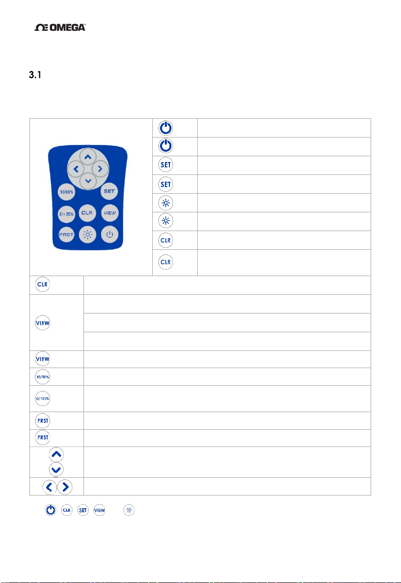
Figure 2 Keypad Button Functional Description
3. OPERATING INSTRUCTIONS
Keypad Functions
The instrument keypad is a twelve (12) key, sealed membrane keypad. Each key provides
audible and tactile user feedback when pressed. Key functions are described in Figure 2
below.
Disable auto-power OFF
(1.5s)
Enter instrument Setup Menu
(1.5s)
Toggle display backlight
Disable backlight 30-second timeout
(1.5s)
(1.5s)
(1.5s)
(1.5s)
The , , , and keys have multiple functions which can be accessed by
momentarily pressing the key, or alternatively, by pressing and holding the key for
While in Setup Menu, save changes and exit menu
Displays Cold Junction Compensation (CJC) readings.
span for the selected TC. Once the output reaches 100% the next press of
Enters the Preset selection mode
Up and Down Buttons: Increment/Decrement currently selected Source digit
by 1.
reset all statistics currently stored in
(1.5s)
3-1
Page 16
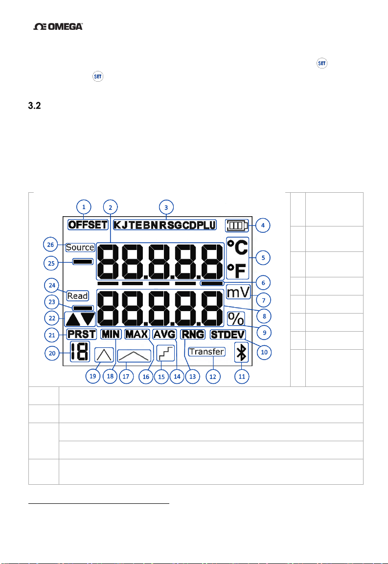
Operating Instructions
OFFSET is
Line 2
Source
digit display
The active
type
Remaining
battery life
Temperature
units
Active Digit
Indicator
milliVolt
designation
population formula) over the last 1000 measurement cycles.
Transfer is active. TRANSFER mode reads the input TC and outputs an offset
reading using the same user settings.
approximately 1.5 seconds. Throughout this Operation Manual, the press and hold sequence
(1.5s)
is indicated by the key designator followed by the subscript (1.5s). For instance,
indicates that the key should be pressed and held for 1.5 seconds, then released to
access the desired function.
LCD Display
The display is a large, easy to read, dual LCD display, with an LED backlight for clear
viewing in low-light conditions. It simultaneously displays Source channel and Read channel
values, current thermocouple type and temperature unit, Source and Read channel labels,
trend indicators for the Read Channel and a battery voltage indicator.
In Statistics View, the initial value displayed is a mirror of the Source channel. Each press
of the View key after that displays the active statistic result and its corresponding label
below. See Figure 3 below for further description of each display indicator.
applicable to
1
Reading in
2
Channel 5
3
thermocouple
4
5
9 Value displayed in Read Channel display is a percentage
Value displayed in the Read Channel is the Standard Deviation (using total
10
Flashing: Broadcasting to pair with a device
4
11
Solid On: Bluetooth connection has paired
12
corrected mV signal to an upstream TC input. Source output is matched to the
4
Bluetooth symbol on LCD reserved for future models.
3-2
6
7
Read
8
Channel 5
digit display
Page 17
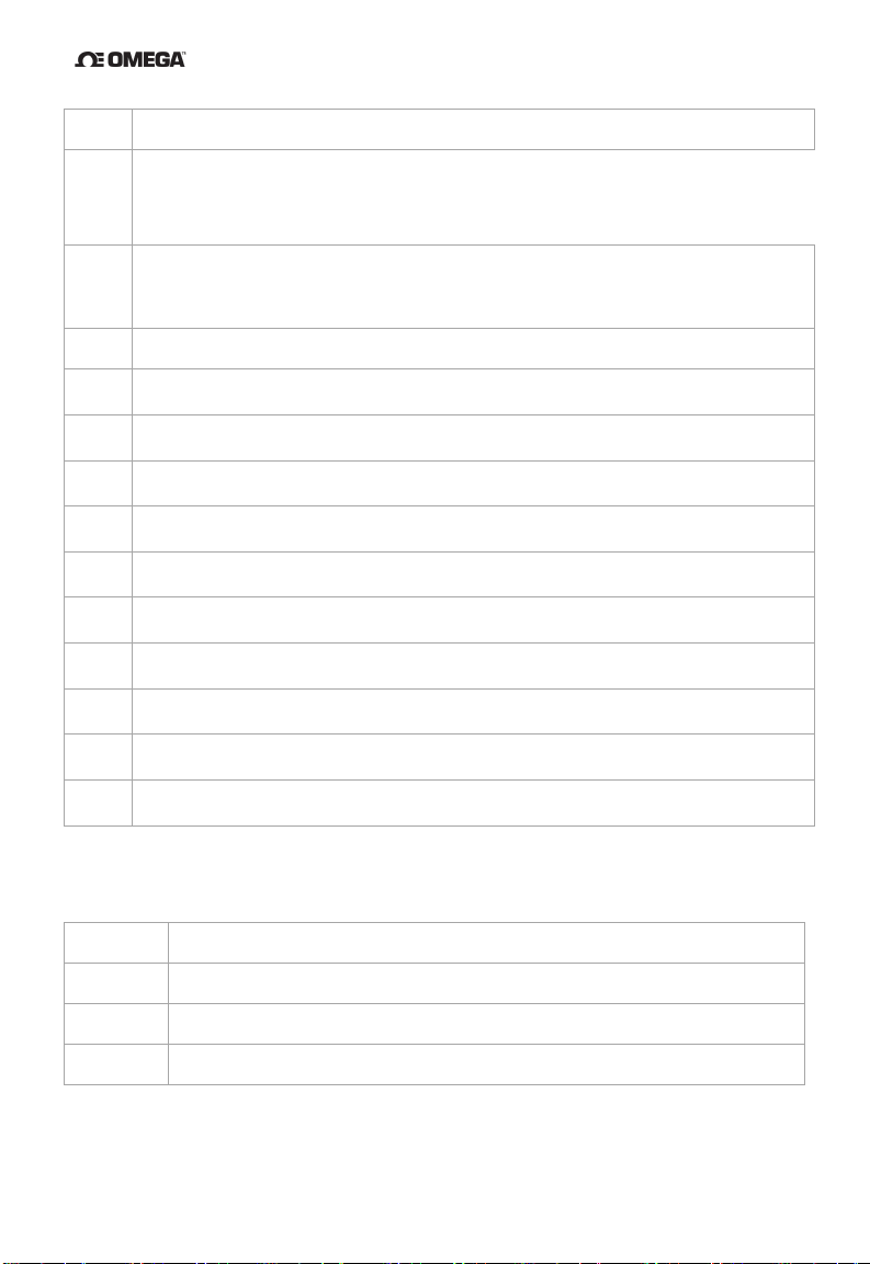
Operating Instructions
MAX statistic. Displays the maximum reading over the last 1,000 measurement
cycles.
0°C. The ramp rate is 5°C per second.
MIN statistic. Displays the minimum reading over the last 1,000 measurement
Fast Ramp: Source Channel continuously cycles from 0°C to Span and then back to
0°C. The ramp rate is 50°C per second.
type if in mV), Units, Mode, Span (0% and 100%), and preset number.
Over Range: The applied temperature is greater than the maximum
temperature for the selected thermocouple type
Under Range: The applied temperature is less than the minimum
temperature for the selected thermocouple type
13 Range is currently displayed, the MAX minus MIN value.
Instrument is displaying the Average reading over the last 1000 measurement
14
cycles.
Step Function: There are 10 equal steps between 0°C and Span. Source
15
continuously steps up and down. There is a 5 second dwell time on each step.
16
Slow Ramp: Source Channel continuously cycles from 0°C to Span and then back to
17
18
cycles.
19
20 Displays the number of the current 20 possible presets, (0-19).
PRST: Preset is active. Each preset value includes Source Value, TC Type, (no TC
21
22 Trend Indicators, Read channel.
23 Minus sign, Read channel.
24 Read channel Label.
25 Minus sign, Source channel.
26 Source channel Label.
Figure 3: LCD Display Description
The LCD can display error information about the current measurement, as shown in Figure
4.
D
ISPLAY DESCRIPTION
OPEn No thermocouple probe is connected
O rnG
U rnG
Figure 4: LCD Error Indications
3-3
Page 18
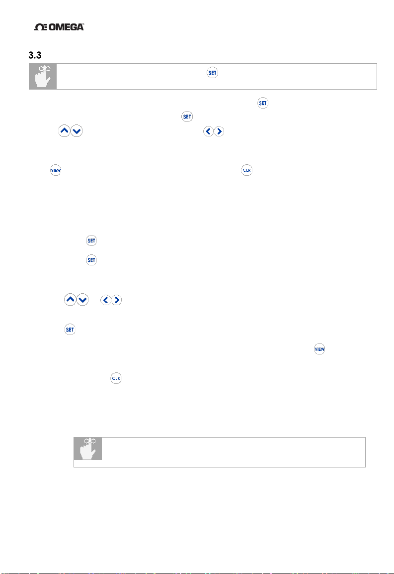
Operating Instructions
Setup Menu
Key designators followed by (1.5s), e.g.
pressed and held for 1.5 seconds, then released to access the desired function.
Measurement settings are configured in the Setup Menu. Press
Menu. From within the Setup Menu, press to step through the user-definable parameters
and the keys to increment/decrement or
Setup Menu. The active parameter value will flash on the display or the active digit indicator
will flash beneath the digit.
Press to save a setting and exit the Setup Menu. Press to disregard unsaved changes
and exit the Setup Menu. If no key is pressed for 10 seconds, the current configuration is
saved and the instrument will exit the Setup Menu.
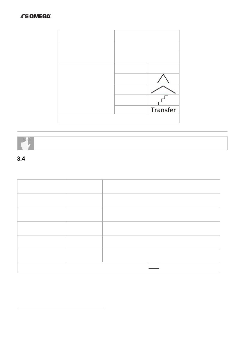
Figure 5 lists the user-definable parameters and the available values for each parameter.
To set a parameter value:
or ;
(1.5s)
;
(1.5s)
to enter the Setup Menu;
1. Press
2. Press to cycle through parameters as shown in Figure 6 until the desired
parameter is reached;
3. To change the value of the current parameter, press
4. To save the current parameter value and cycle to the next parameter, press
5. To save the current parameter value and exit the Setup Menu, press ;
6. To disregard changes made to the current parameter value and exit the Setup
Menu, press .
7. If parameter 2, “Temperature and Voltage Units” are set as either “°C” or “°F”, the
remaining parameter choices available are in Figure 5 below under “Setup Choices
for °C and °F”. If parameter 2 is set to “mV”, the remaining parameter choices
available are in Figure 5 below under “Setup Choices for mV”.
(1.5s)
, indicate that the key should be
(1.5s)
to access the Setup
keys to move left/right while in the
STATS
are not active in mV mode.
3-4
Page 19
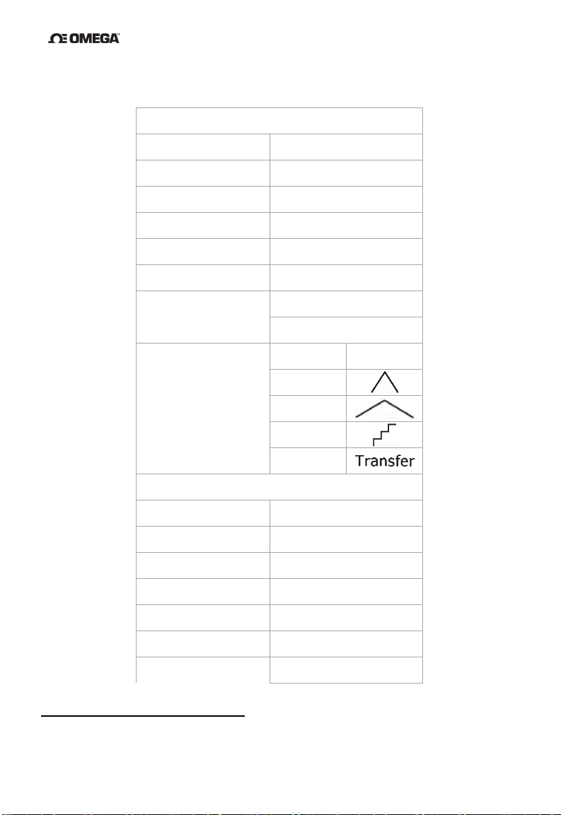
Operating Instructions
Temperature and
voltage Units
(old)
blinking
voltage Units
(old)
SETUP MENU CHOIC ES FOR °C AND °F
PARAMETER AVAILABLE VALUES
Thermocouple Type5 K, J, T, E
°C, °F, mV
Probe Offset ±0.1 ° increments
Open Lead detection
On / Off
Source (SourC) On / Off
If on – Set Span
If on – Set Mode
SETUP MENU CHOIC ES FOR MV
PARAMETER
Thermocouple Type
Temperature and
Probe Offset
Open Lead detection
Source (SourC)
If on – Set Span
Set 100% Level
Set 0% Level
Manual
Fast Ramp
Slow Ramp
Step
Transfer
AVAILABLE VALUES
6
K, J, T, E
°C, °F, mV
±0.1mV increments
On / Off
On / Off
Set 100% Level
5
“__ __ __ __ ”
5
The CL945A includes K,J,T,E,B,N,R,S,G,C,D,P,L,U
6
All though still selectable, TC type is not visible on LCD while mV is the active unit
3-5
Page 20
Operating Instructions
Range Hi mV (default)
[-15mV to +85mV]
Range Lo mV7
[-15mV to +35mV]
blinking
D
INDICATOR
Minimum temperature recorded during current
session
Maximum temperature recorded during current
session
Average of all temperatures recorded during
current session
Standard deviation of all temperatures recorded
during the current session1.
Set 0% Level
Range (rAnGE)
Manual
(mV flashing)
“__ __ __ __”
Fast Ramp
If on – Set Mode
Slow Ramp
Step
Transfer
7
Low range is for calibration verification only.
Figure 5
If no key is pressed for 10 seconds, the instrument will save the current configuration
and exit the Setup Menu.
View Modes and Statistics
The instrument features multiple view modes including a variety of real-time statistics, all
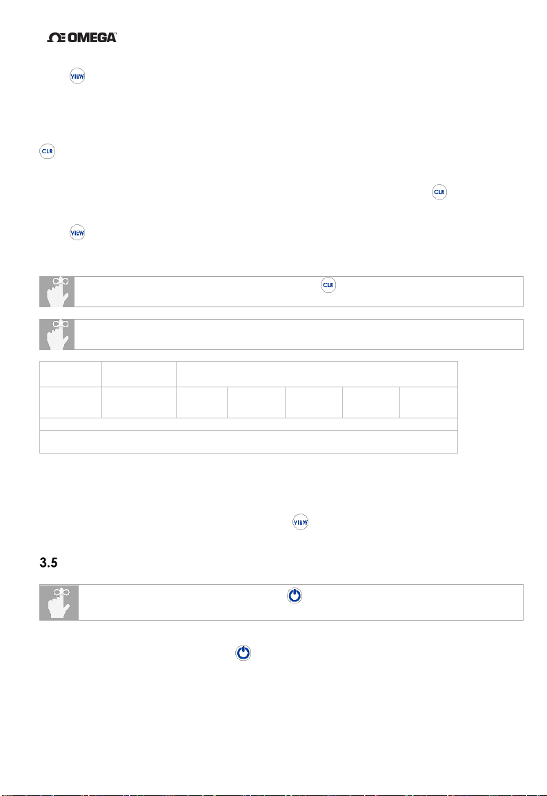
available at the touch of a button. Figure 6 below describes each view mode.
VIEW MODE
Minimum MIN
Maximum MAX
ISPLAY
DESCRIPTION
Average AVG
Range RNG Maximum minus Minimum
Standard Deviation STDEV
1
Standard Deviation is calculated using the population formula: =
Figure 6: View Modes and Statistics
3-6
2
∑
(−µ)
�
Page 21
Operating Instructions
results and initiate a new statistics session.
M
S
S
Value from
channel
Press to change view modes. For each mode, the active measurement or statistic result
is displayed on the second line of the display.
When viewing statistics, the active statistic is indicated directly below the result.
Statistics are calculated continuously, beginning when the instrument is powered on or when
(1.5s)
is pressed.
It is important to note that changing parameter values or temperature probes will invalidate
(1.5s)
the current statistics session. When using statistics, always begin by pressing
delete existing statistics data and initiate a new statistics session.
Press to step through the available statistics. Statistics are displayed in the order shown
in Figure 7 below.
to
When using statistics, always begin by pressing
(1.5s)
to clear existing statistics
The first line of the display indicates the current Source Channel value, regardless of
which view mode statistic is currently displayed.
ODEL
OURCE
TATISTIC VIEW SEQUENCE
CHANNEL
CL940A/
CL945A
source
MIN MAX AVG RNG STDEV
Figure 7: Statistics Sequence
If the instrument records invalid measurement data during the statistics session such as an
over-range, under-range, or open input value, ————— will be displayed for each affected
statistic result.
To return to the active measurement mode, press repeatedly to step through the
remaining view modes, or cycle power.
Auto-Power Off
Key designators followed by (1.5s), e.g.
pressed and held for 1.5 seconds, then released to access the desired function.
To conserve battery life, the instrument automatically turns off if no key is pressed for 20
minutes. To disable this feature, press
(1.5s)
once, indicating auto-power off is disabled.
Auto-power off will remain disabled until instrument power is cycled. At next power on,
auto-power off returns to the default enabled condition.
(1.5s)
, indicate that the key should be
. The remaining battery life indicator will flash
3-7
Page 22
Operating Instructions
D
INDICATOR
Instrument operates by outputting a voltage that
millivoltage.
Instrument Ramps the output temperature or
millivoltage) and clear the fast ramp setting.
Instrument Ramps the output temperature or
millivoltage) and clear the slow ramp setting.
Instrument Ramps the output temperature or
millivoltage) and clear the Step ramp setting.
Instrument sets the source output (temperature
“Transfer” icon will blink and illuminate if selected.
Backlight and Backlight Timeout
The instrument includes an LED backlight feature to ensure measurement data can be easily
read in low-light conditions. To activate the backlight, press .
Once the backlight is activated, it will automatically turn off after 30 seconds if no key is
(1.5s)
pressed to preserve battery life. To disable the backlight timeout feature, press
backlight will flash to indicate the timeout feature has been disabled. To re-enable the
backlight timeout feature, turn the backlight off then on by pressing twice.
. The
Operating Modes
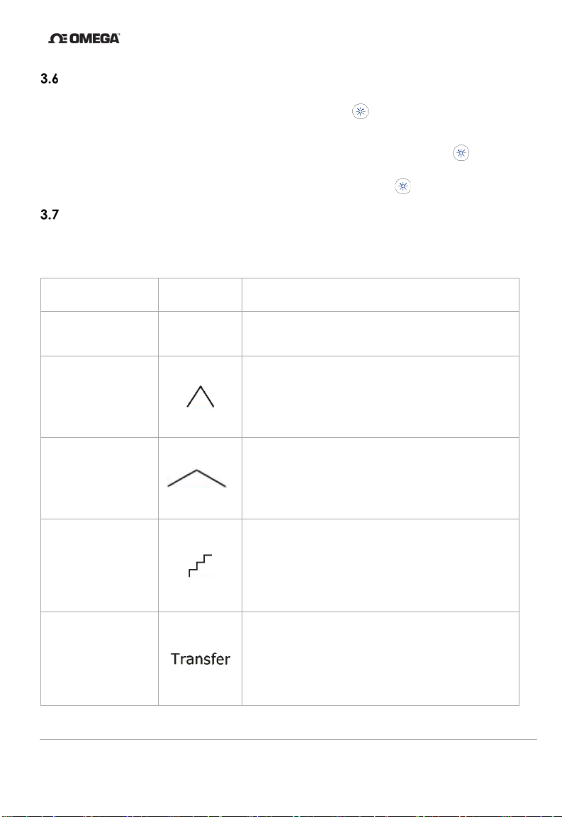
The instrument has five (5) operating modes for channel one, “Source” including manual
operation explained in Figure 8 below. The operating modes are Manual, Fast ramp, slow
ramp, step and transfer.
OPERATING MODE
Manual
Fast Ramp
Slow Ramp
Step
Transfer
ISPLAY
blinking
“__ __ __ __”
DESCRIPTION
corresponds to the set temperature or
millivoltage from 0% of span to 100% of span and
back to 0% of span in 20 seconds. This repeats
until stopped. Any other key press will stop the
output at the existing value (temperature or
millivoltage from 0% of span to 100% of span and
back to 0% of span in 120 seconds. This repeats
until stopped. Any other key press will stop the
output at the existing value (temperature or
millivoltage from 0% of span to 100% of span and
back to 0% of span stepping at 10% increments,
dwelling 5 seconds at each step. This repeats
until stopped. Any other key press will stop the
output at the existing value (temperature or
or millivoltage) equal to the value on the “Read”
channel, (channel 2). This is an offset corrected
value. SOURCE output = READ voltage + CJC
voltage. This mode would be used for
troubleshooting systems and readouts. The
Figure 8: Operating Modes
3-8
Page 23
Operating Instructions
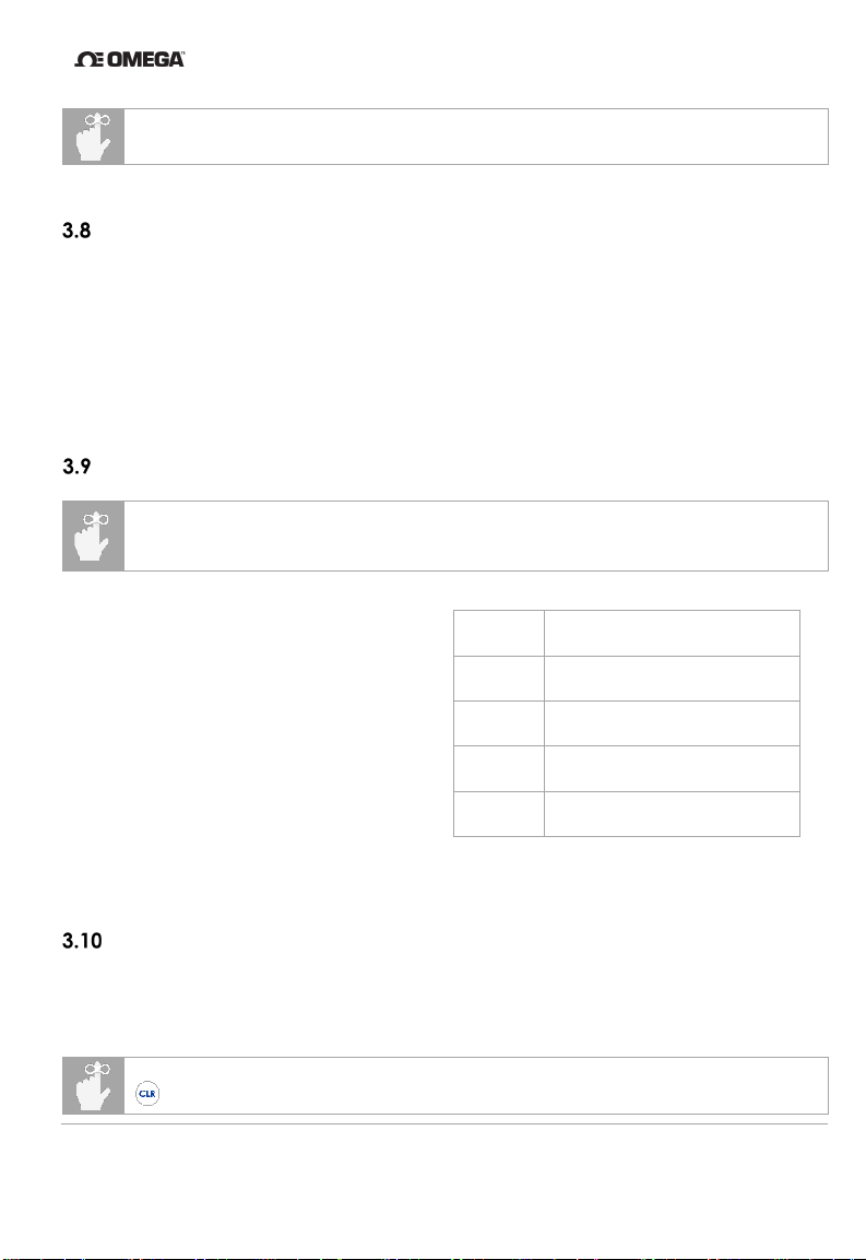
While in any of the Operating Modes above, unless Auto Power Off was disable, the
instrument will automatically turn off if no key is pressed for 20 minutes.
Trend Indicators
Trend indicators provide a visual representation of the measurement’s stability, and are
provided for the Read channel. An up arrow indicates that the current measurement is
trending upwards, while a down arrow indicates the measurement is trending downwards.
The trend indicators code looks for a greater than, plus or minus 0.1 degree change in 5
seconds. It will then light the up or down arrow based on which way the temperature is
moving. If the temperature change for the last 5 seconds is less than 0.1 degrees, the
indicators will go off. Neither arrow is visible when the measurement is stable. For best
accuracy, always allow the measurement to stabilize before evaluating or recording the
measured temperature.
Battery Indicator
Battery depletion or battery replacement will reset all measurement parameters to
their default values and deletes all existing statistics data. After battery replacement,
set measurement parameters as required.
The battery voltage indicator provides a visual representation of approximate remaining
battery life. It is located at the top-right of the
display.
The battery voltage indicator uses three bars
to represent remaining battery life. Figure 9
shows the approximate battery life for each
bar.
At zero (0) bars, the instrument will display
“Chang Bttry” for 30 seconds and then
initiate a shutdown sequence. To prevent
disruption of the measurement process and
statistics and data collection, the batteries
should be replaced before the battery voltage
indicator reaches zero (0) bars. See Section 2.5, Battery Installation and Replacement.
BARS APPROX. BATTERY LIFE
3 100% - 50%
2 50% - 20%
1 20% - 5%
0 0% - Shutdown Initiated
Figure 9: Battery Voltage Indicator
Probe Offset
The probe offset feature compensates for temperature probe errors, significantly improving
overall measurement uncertainty. Probe offset can be set for the Source Channel. Once set,
the probe offset is automatically applied to all subsequent measurements and statistics on
the offset channel.
Current statistics will be invalidated after changing settings such as probe offset. Press
(1.5s)
to delete existing statistics data and initiate a new statistics session.
3-9
Page 24
Operating Instructions
Probe offset rounding errors may occur if temperature units are changed while a
programmed probe offset after changing temperature units.
Neither trend indicator is
has stabilized.
probe offset is active. When using a probe offset, verify and if necessary correct the
To set the probe offset when using an un-calibrated temperature probe:
1. Connect the temperature probe to the Read Channel of the instrument;
2. Place the probe into a known temperature reference such as a thermowell or ice
3. Allow the temperature probe to stabilize in the ice bath or thermowell by observing
4. Press
5. Press two (2) times to cycle to the
6. Observe the current offset displayed on the top segments of the display, and
7. Press to increment/decrement the currently selected digit until the
8. Press to save the offset value and proceed to Open lead detection or press
9. OFFSET is displayed at the top-left of the LCD display.
To set the probe offset when using a calibrated temperature probe with a known offset:
8
;
bath
the instrument trend indicators for the
Read channel;
(1.5s)
to enter the Setup Menu;
Offset parameter;
current Read value displayed on the second line of the display;
displayed temperature equals the known temperature reference value. Press
to change the digit place;
to save the offset value and exit the Setup Menu.
a. Alternatively, to disregard the new offset value and exit the Setup Menu,
press .
displayed when the
temperature measurement
1. Press
2. Press two (2) times to cycle to the Offset parameter;
3. Observe the current offset value displayed on the first line of the display;
4. Press to increment/decrement the currently selected digit until the
displayed temperature equals the known temperature reference value. Press
8
Probe offset measurement using an ice bath or thermowell should only be performed by personnel trained
and qualified in the use of such instruments and related metrology methods.
(1.5s)
to enter the Setup Menu;
to change the digit place;
3-10
Page 25
Operating Instructions
5. Press to save the offset value and proceed to Open lead detection or press
to save the offset value and exit the Setup Menu.
a. Alternatively, to disregard the new offset value and exit the Setup Menu,
press .
6. OFFSET is displayed at the top-left of the LCD display.
Open Lead Detection Enable/Disable
Open Lead Detection allows the unit to detect if a thermocouple probe is connected to the
thermometer. This feature is not compatible with some thermocouple calibrators and can
result in measurement instability.
Disabling Open Lead Detection in these situations can significantly improve reading stability.
Once disabled, Open Lead Detection will remain disabled until changed by following
the below steps, or the instrument is powered off.
If no thermocouple probe is connected and Open Lead Detection is disabled, the unit
will not indicate OPEn and may display erratic readings.
To change the Open Lead Detection setting:
1. Press
2. Press three (3) times to cycle to the Open Lead Detection parameter;
3. Press to change the Open Lead Detection setting;
4. Press or to save the Open Lead Detection setting and exit the Setup
Menu.
(1.5s)
to enter the Setup Menu;
a. OLd is displayed on Line 1 of the LCD, and the current Open Lead
Detection status is displayed on Line 2, On/OFF.
a. ON indicates that Open Lead Detection is enabled;
b. OFF indicates that Open Lead Detection is disabled;
a. Alternatively, to disregard the Open Lead Detection setting and exit the
Setup Menu, press .
Clear Function
From active measurement mode, press
new statistics session. The LCD display will indicate CLEAr to confirm the action and return
to active measurement mode.
(1.5s)
to clear the statistics registers and begin a
3-11
Page 26
Operating Instructions
Pressing
internal memory except for Presets.
From the Setup Menu, press to disregard changes to the current parameter value and
exit the Setup Menu.
(1.5s)
deletes all measurement data currently saved in the instrument’s
Presets: Save, Recall and Erase
There are 20 presets in the instrument numbered 0 – 19. The presets allow the user to save
the parameters chosen during setup. There are 3 preset actions. The user can save, recall
or erase.
When a preset is saved, the current operating options are stored in one of the 20 selected
presets. The operating options include:
• Thermocouple Type
• Units
• Offset
• Open Lead Detection Status
• 100% and 0% Span Settings
• Operating Mode: Fast Ramp, Slow Ramp, Step or Transfer
To save a preset
(1.5s)
Press the
preset number location you want to use to store the current operating options. Press the
. The preset number will start flashing. Use the to move to the
. The current operating options are now saved in the chosen preset location and the
flashing stops.
To recall a preset
Press the button. “PRST” will begin to flash. Use the to move to the desired
saved preset, 0-19. When the desired preset is reached, press the preset button again to
exit. The instrument will only display the numbers where presets are stored. For example:
If there are presets stored in 3 and 10 and all others are empty, in this case the would
only toggle between and display 3 and 10.
To erase a preset
To erase a preset it must first be recalled by following the “To recall a preset” steps above.
(1.5s)
Once the desired preset is recalled, press the
flashing. While the preset number is flashing, press
3-12
. The preset number should now be
(1.5s)
. “CLEAr” will appear on the LCD
Page 27
Operating Instructions
The current measurement or statistic is over-range for the selected
display.
The current measurement or statistic is under-range for the
selected thermocouple type
A thermocouple, shorted transducer, or other short circuit is
plugged into the Source Channel during startup.
momentarily. The location is now empty and will not appear with any of the saved presets
when trying to recall a preset.
The preset number just erased will still appear on the LCD until moved from that
preset number. Once moved to a different preset, it will no longer appear when
trying to recall a preset.
Invalid Measurement Indications
The LCD display indicates when a measurement or statistic is invalid, as shown in Figure 10
below.
I
NDICATION DESCRIPTION
O rnG
U rnG
OPEn No probe is connected or the probe sensor is faulty
————— Cannot compute a valid statistical result
Short ChAn1
thermocouple type. Also, Instrument is in mV mode, “old” is off
and “Source” is off. Those settings can lead to an Over range
Figure 10: Invalid Measurement Indications
3-13
Page 28

Service Information
4. SERVICE INFORMATION
Inspection and Cleaning
To extend the life of the instrument, inspect and clean the instrument regularly. Inspect the
instrument for any significant abrasions, cuts, cracks, dents, or other signs of damage on
the case, keypad, and display lens. Inspect the connectors for breaks, dirt, or corrosion.
Ensure all screws are securely fastened, and if equipped, that the tilt stand/magnet/hanger
is in good condition and locks into position properly.
With all screws securely fastened and the battery compartment cover in place, use a damp
cloth or towel to wipe down the instrument. Use care to avoid scratching the display lens.
Mild, non-abrasive detergents may be used providing the instrument is then wiped down
with a clean damp cloth or towel.
Calibration
4.2.1 Verification Procedure
The voltage calibration of the instrument can be verified by checking the mV points noted in
Figure 12 below. A Digital Multi-Meter with suitable accuracy
Copper mini-TC male connectors, with good quality, low-thermals wire. The wire cannot be
tinned.
1. This procedure shall be performed within environmental conditions of 23 ±1 °C
and 5% to 95% RH.
2. The unit under test (“UUT”) shall be acclimated to the Controlled Environment for
a minimum of four (4) hours.
9
is needed along with a set of
3. Disable the auto-power off feature by pressing
indicator will flash once, indicating auto-power off is disabled.
4. Connect a copper daisy-chain from Source Channel 1 to Read Channel 2 and to a
DMM of suitable accuracy
9
Suitable accuracy means a metrology-grade DMM. To achieve mV limits shown in Appendix C, the DMM must
have accuracy equivalent to 30 ppm of reading and 9 ppm of range on the 100mV range.
9
.
4-14
(1.5s)
. The remaining battery life
Page 29
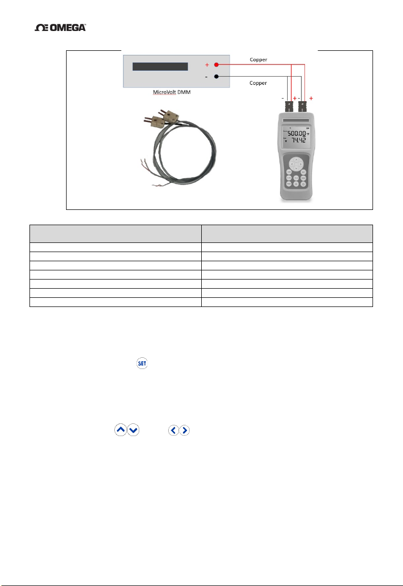
Service Information
Figure 11
High range: (in mV)
[-15mV to +85mV]
Low range: (in mV)
[-15mV to +35mV]
-13.000
-13.000
-10.000
-10.000
0.000
0.000
5.000
10.000
20.000
30.000
80.000
33.000
83.000
n/a
Figure 12
5. Use the Instrument Verification Data Sheet, Appendix C to verify the
measurements in Figure 12 above.
6. Enter setup mode,
“mV” and rAnGE = “Hi”.
7. Connect the Positive of the Source and Read channels to the positive input of the
DMM. Connect the negative of the Source and Read channels to the negative
input of the DMM.
8. By using the and/or
each value in Figure 12 in the “High range”, notating the result from the DMM on
the “Instrument Verification Data Sheet”, Appendix C in “Source DC Volts Channel
1” “Measurement Result” and “Measure DC Volts Channel 2” “Standard” column.
9. Pass/Fail Criteria:
a) For “Source DC Volts Channel 1”, a PASS result is any “Measurement Result”
value that is equal to or in between the Lower Limit and Upper Limit error
numbers.
(1.5s)
and ensure the following parameters are set: units =
keys, adjust the instrument Source to match
4-15
Page 30

Service Information
b) For “Measure DC Volts Channel 2”, Calculate the limits of error by
adding/subtracting the value noted in the “Tolerance” column to the value of
the “Standard” column for each setpoint. A PASS result is any “Measurement
Result” value that is equal to or in between the Lower Limit and Upper Limit
error numbers.
10. Enter setup mode,
(1.5s)
and ensure the following parameters are set: units =
“mV” and rAnGE = “Lo”.
11. By using the and/or
keys, adjust the instrument Source to match
each value in Figure 12 in the “Low range”, notating the result from the DMM on
the “Instrument Verification Data Sheet”, Appendix C in “Source DC Volts Channel
1” “Measurement Result” and “Measure DC Volts Channel 2” “Standard” column.
12. Pass/Fail Criteria:
c) For “Source DC Volts Channel 1”, a PASS result is any “Measurement Result”
value that is equal to or in between the Lower Limit and Upper Limit error
numbers.
d) For “Measure DC Volts Channel 2”, Calculate the limits of error by
adding/subtracting the value noted in the “Tolerance” column to the value of
the “Standard” column for each setpoint. A PASS result is any “Measurement
Result” value that is equal to or in between the Lower Limit and Upper Limit
error numbers.
13. To verify the Cold Junction Compensation, (CJC) of the Source, (Channel 1) and
Read, (Channel 2).
14. Place the CL940A in a Controlled Environment
thermometer
11
for one hour to stabilize. Compare CJC readings with the reference
thermometer reading. Display the CJC temperature by pressing
10
along with an accurate
(1.5s)
. The
screen will display “CJC 1” and the current temperature of CJC 1 in °C. Pressing
the key again will display “CJC 2” and the current temperature of CJC 2 in °C.
Notate the results in the “Cold Junction Compensation” section on the Instrument
Verification Data Sheet, placing the Thermometer reading in the “Standard”
column, and the CJC readings in the “Measurement Result” column. Select to
exit.
10
An insulated box inside a calibration lab environment, see Appendix A.
11
An accurate thermometer specification is 2 Sigma uncertainty ≤ .04°C (40mK) at the verification
temperature.
4-16
Page 31
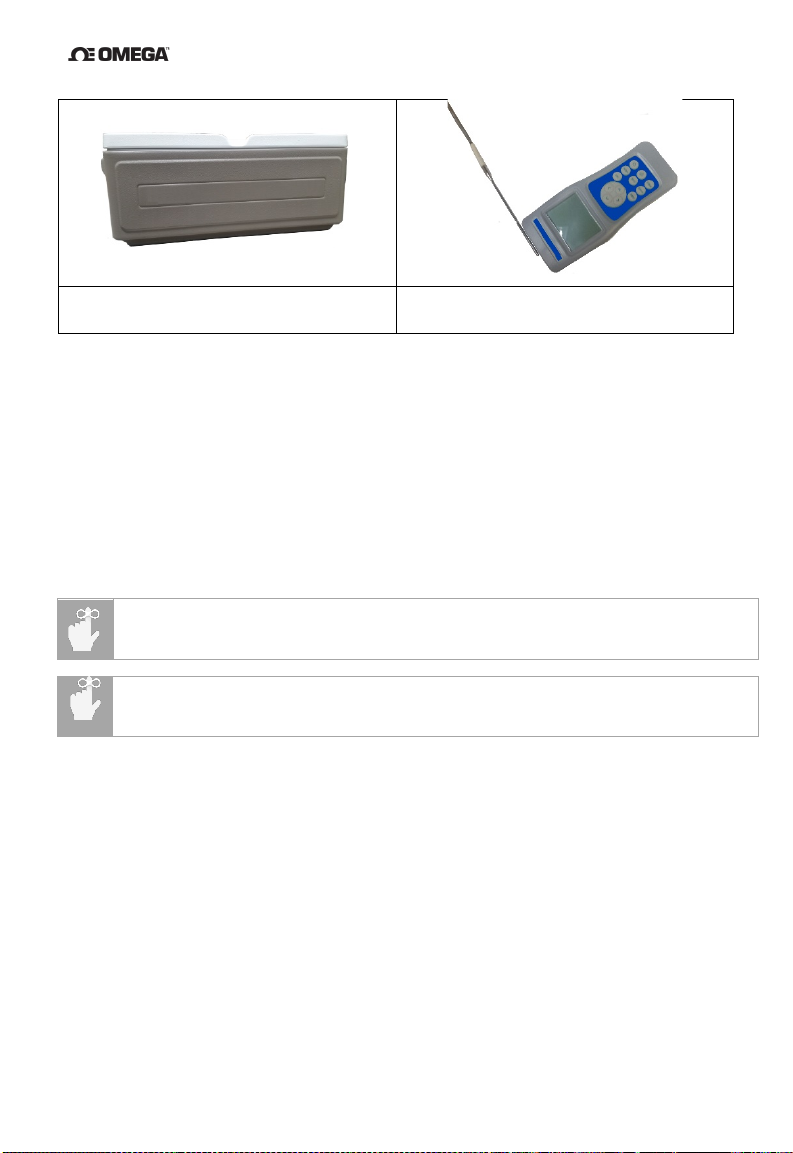
Service Information
Insulated container with lid for controlled
Position accurate thermometer sensor in
Figure 13
For best results, the instrument keypad is the only part of the instrument that should
environment
15. Calculate the Lower and Upper limits: First add a factory determined offset of
0.06°C to the “Standard” value, then add/subtract 0.11°C from the result. For example:
the thermometer reading stabilized at 23.82°C; add .06°C offset to get 23.88°C, then
determine the upper limit as 23.99°C (23.88 + 0.11), and the lower limit as 23.77°C (23.88
minus 0.11). The CJC values should be no greater than these limits. (NOTE: The 0.11°C
value is derived from the 0.15°C specification minus the .04°C uncertainty of the
temperature measurement device.)
middle of MTC 1 and 2 as shown above
4.2.2 Alignment Procedure
Published temperature uncertainty values can only be achieved if the temperature of
UUT is known within 40mK. Customers performing CJC adjustments in their facility
will need to calculate their own uncertainty.
be touched after the acclimation period inside the controlled environment. The
temperature sensor should not be touched.
1. This procedure shall be performed within environmental conditions of 23 ±1 °C
and 5% to 95% RH.
2. The unit under test (“UUT”) shall be acclimated to the Controlled Environment for
a minimum of four (4) hours. The customer supplied calibrated temperature
measurement device used for CAL 11 and CAL 12 below shall also be acclimated in
the same Controlled Environment simultaneously with the UUT.
3. The equipment listed in Appendix A is required to align the UUT to operate within
the expanded instrument uncertainties for mV values specified in Appendix B.
Customers performing CJC adjustments in their facility will need to calculate their
own CJC uncertainty.
4. Remove the UUT battery door housing to expose the alignment access hole.
4-17
Page 32
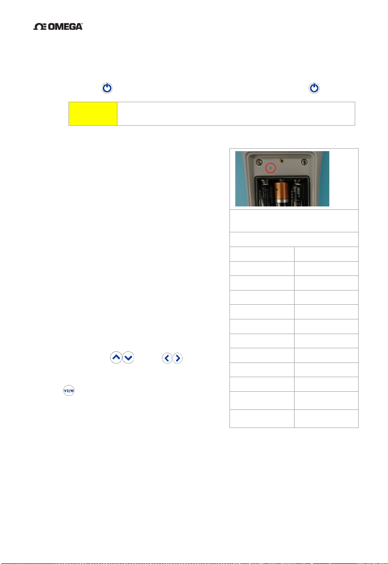
Service Information
Figure 14: Alignment Access Hole
Location
CAL 1
-10.000 mV
CAL 2
80.000 mV
CAL 3
-10.000 mV
CAL 4
80.000 mV
CAL 5
-10.000 mV
CAL 6
30.000 mV
CAL 7
-10.000 mV
CAL 8
80.000 mV
CAL 9
-10.000 mV
CAL 10
30.000 mV
External measured
temperature in °C
External measured
temperature in °C
Figure 15
5. Connect the Positive of the Source and Read channels to the positive input of the
DMM. Connect the negative of the Source and Read channels to the negative
input of the DMM.
6. Press UUT to turn the UUT on. Disable the Auto-Power Off press
CAUTION
Do not apply voltages greater than 83 mV DC to the UUT inputs. Voltages
greater than 83 mV may damage the instrument.
7.
Insert the Straightened Paper Clip through
the alignment access hole and gently press
the calibration enable switch located on the
circuit board to enter CAL mode. See Figure
14 for location.
Temporary calibration values are set to a
gain of 1 and offset of 0 every time
calibration is entered. If the calibration is
accepted and saved without entering new
values, the temporary values are copied to
the system values for use.
Voltage Gain and Offset Alignment
8. The UUT display will indicate as follows:
a. Line 1: “-10.000”
b. Line 2: “CAL 1”
The instrument is now sourcing
-10.000 mV.
9. By using the and/or
keys,
adjust the instrument to match as close as
possible the DMM display voltage. Use the
key to save the settings and advance to
“CAL 2”. Repeat this step to and including
CAL 10.
CAL 11
CAL 12
10. CAL 11 and CAL 12 are used to set the Cold
Junction Compensation, (CJC) of the
Source, (Channel 1) and Read, (Channel 2). These steps require the use of a
customer supplied calibrated temperature measurement device. With the probe as
close as reasonable to the channel 1 CJC, and temperature stabilized, enter the
externally measured temperature in Celsius for channel 1. Repeat this step for
Channel 2, CAL 12. See figure 13 above.
(1.5s)
4-18
Page 33
Service Information
Statistics)
Unexpected or
Measurement
Set probe offset to correct value
(see Section 3.10, Probe Offset)
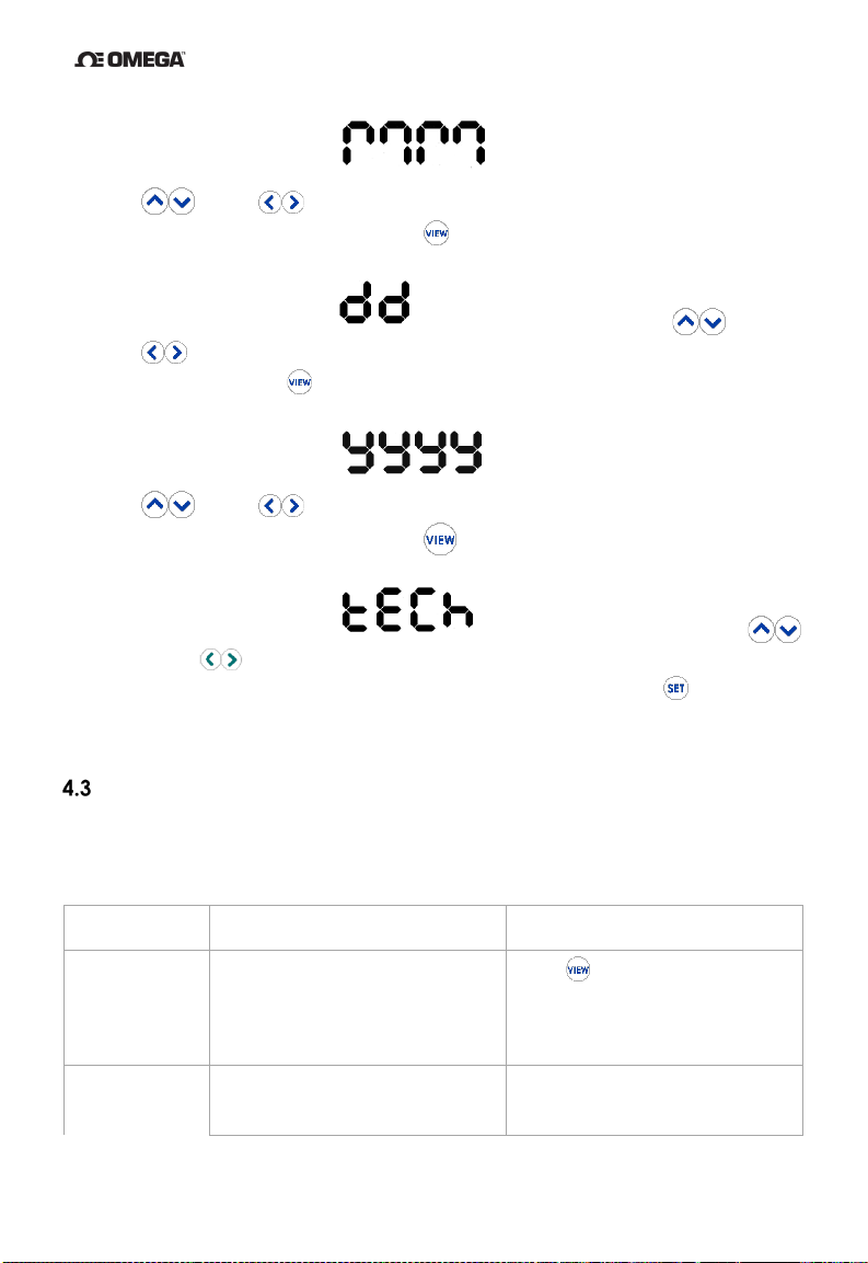
11. The device now displays for a 2-digit month. By using the
and/or
calibration being conducted. Press to save and advance to day.
12. The device now displays for a 2-digit day. By using the and/or
keys, adjust the instrument to the 2-digit day for the calibration being
conducted. Press to save and advance to year.
13. The device now displays for a 4-digit year. By using the
and/or
calibration being conducted. Press to save and advance to Tech ID.
14. The device now displays for a technician ID. By using the
and/or keys, adjust the instrument to the calibration technician ID. Select a
value from 0 – 99999 for the calibration technician ID and press to save and
exit.
keys, adjust the instrument to the 2-digit month for the
keys, adjust the instrument to the 4-digit year for the
Troubleshooting
OMEGA’s digital handheld thermometers are designed and built to provide years of
uninterrupted use. In the event the instrument malfunctions or does not perform as
expected, helpful troubleshooting tips are provided below. Figure 14 below lists some of the
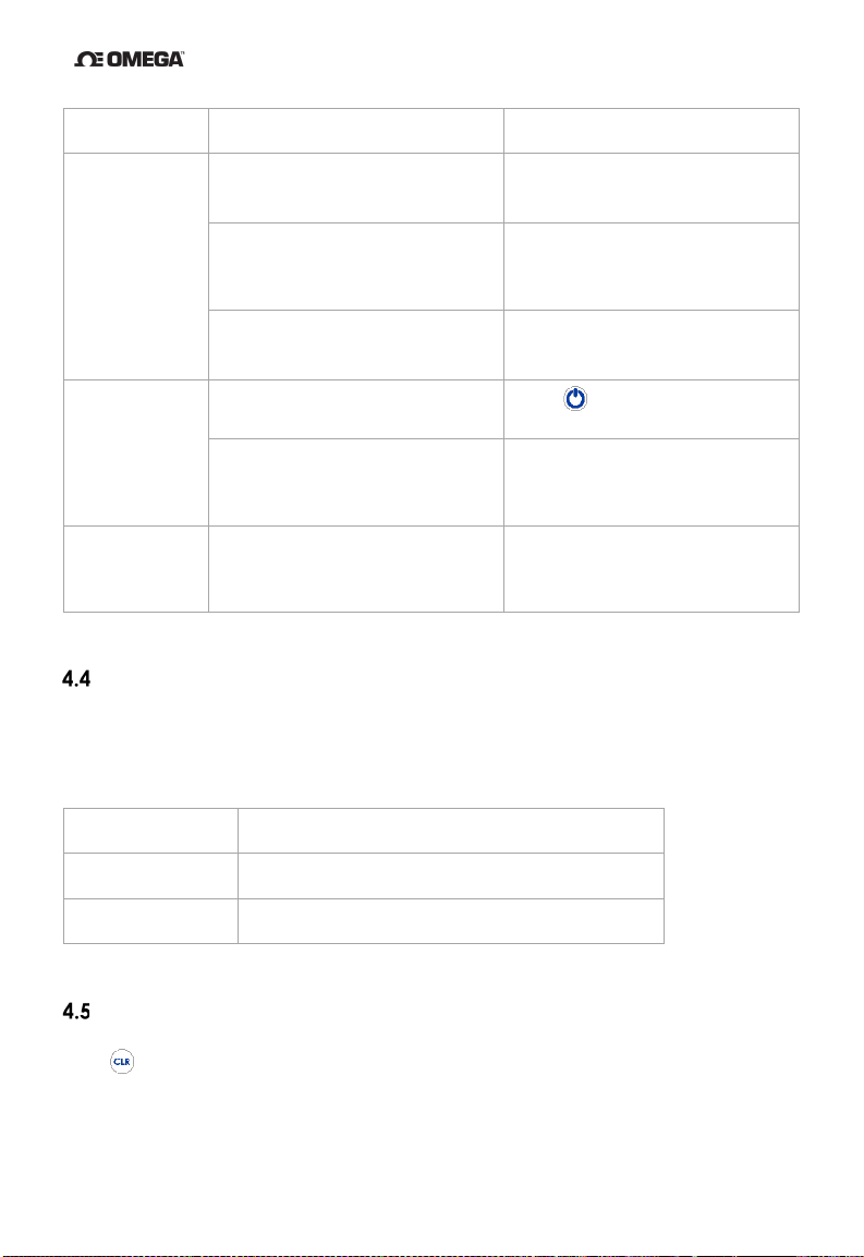
more common issues and their resolutions.
S
YMPTOM DESCRIPTION RESOLUTION
Unexpected
reading on
Line 2 of
Display
Erroneous
Statistics View Mode is active
Probe offset is active
4-19
Press to cycle through
statistics views until active
measurement is displayed (see
Section 3.4
for connected temperature probe
View Modes and
Page 34
Service Information
Observe display trend indicators
(see Section 3.8 Trend Indicators)
Set the thermocouple type as
Menu)
When sourcing from a
Lead Detection is enabled.
See Section 3.11, Open Lead
disable.
power
Shuts down
power on
Replace batteries (see Section
A thermocouple, shorted
Channel during startup.
Remove the shorting device. Be
SYMPTOM DESCRIPTION RESOLUTION
Unresponsive
unexpectedly
or will not
Display shows
“Short ChAn1”
on power up.
Temperature probe has not
stabilized
Instrument is set to the wrong
thermocouple type for the
attached probe
thermocouple simulator, Open
Static discharge through
connected probes
Batteries are low or depleted
transducer, or other short circuit
is plugged into the Source
Figure 16: Common Troubleshooting Issues
and wait for stable measurement
appropriate for the attached
probe (see Section
Detection Enable/Disable to
Press to cycle instrument
2.5, Battery Installation and
Replacement)
sure thermocouple is plugged into
the Read Channel, not Source.
3.3, Setup
Diagnostic Routines and Error Codes
The instrument momentarily activates all display annunciators and segments during startup
to allow for visual inspection of the LCD. Observe the LCD and verify all segments activate.
Internal diagnostic routines are also executed during startup. If any diagnostic routine
detects a malfunction, an error will be displayed as shown in Figure 17 below.
E
RROR CODE DESCRIPTION
Err ADC Analog to digital converter error
Err InP Stuck key or other keypad error
Figure 17: Diagnostic Routine Error Codes
Memory Sterilization
To erase all locally stored measurement data and reset accumulated statistics,
press
Instrument parameters will be retained. Refer to Section 3.3, Setup Menu to set instrument
parameters as desired.
(1.5s)
. See Section 3.12, Clear Function for instructions.
4-20
Page 35

Service Information
Statement of Calibration
This instrument has been inspected and tested in accordance with
specifications published by OMEGA, Inc.
OMEGA, Inc. certifies the above listed instrument has been inspected and
calibrated and meets or exceeds all published specifications and has been
calibrated using standards whose accuracies are traceable to the
International System of Units (SI) through the National Institute of
Standards and Technology (NIST) or other recognized National Metrology
Institutes.
4-21
Page 36

Appendices
EQUIPMENT
FUNCTION
RANGE
SPECIFICATION (2-SIGMA)
DC Voltage
Measurement
Measure
junction test.
NOTE: This process requires a set of COPPER mini-TC connectors, with good quality,
Straightened
Paper Clip
Required to access the calibration enable switch. Any rigid wire, approximately 0.8
mm in diameter, may be used.
A. REQUIRED EQUIPMENT
DMM
Calibrated
temperature
measurement
device
Controlled
Environment
Copper MiniTC Cable
-13mV to 83 mV
ambient
temperature
during cold
Insulated box to create a Controlled Environment; a very stable, low gradient air
bath.
low-thermals wire. These cannot be tinned.
(2) Copper Mini-TC Cables required for Voltage Gain and Offset alignment only. This
cable does not require calibration. See Figure 11 above.
One end shall be terminated with a male miniature copper thermocouple connector for
connection to the UUT. The opposite end shall be terminated with copper connections
appropriate for the DMM.
18°C to 28°C ±40 mK (.04°C)
± (30 ppm of reading + 9 ppm of range)
A-i
Page 37
Appendices
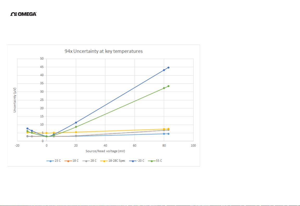
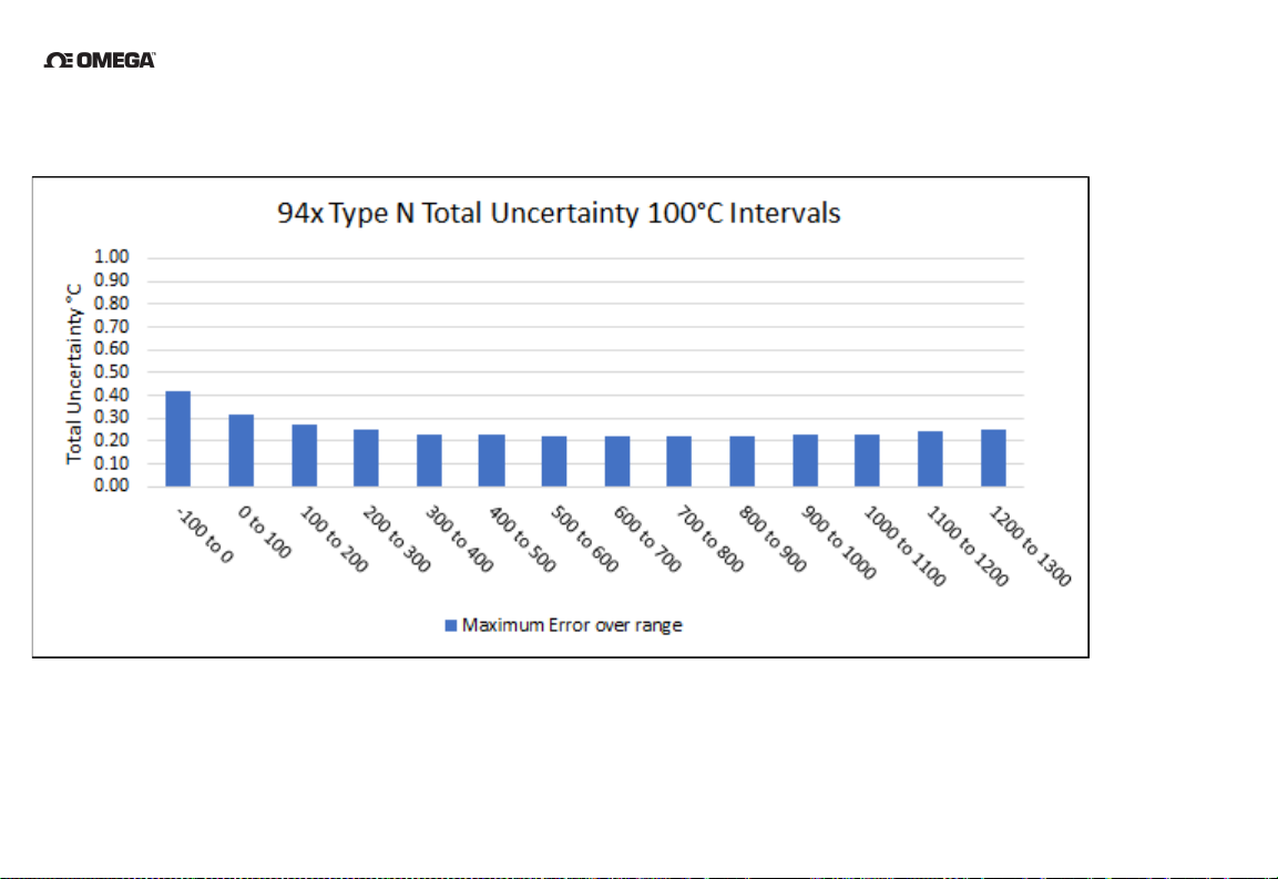
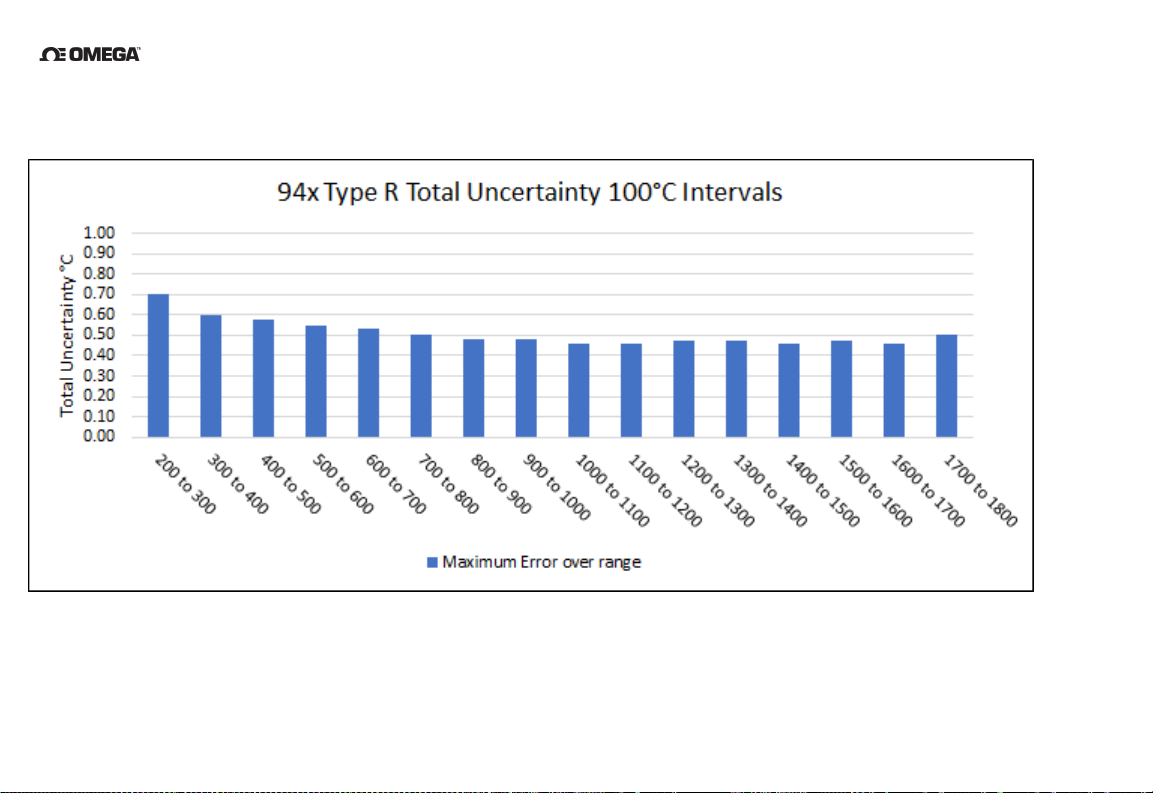
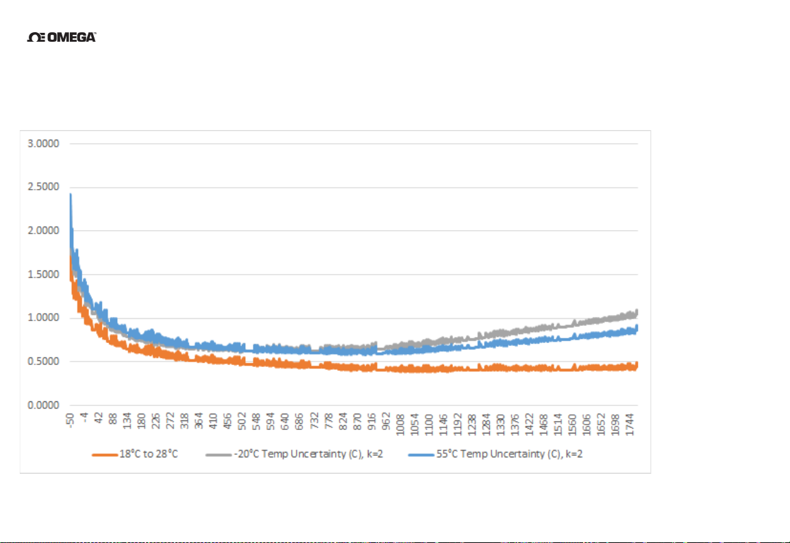
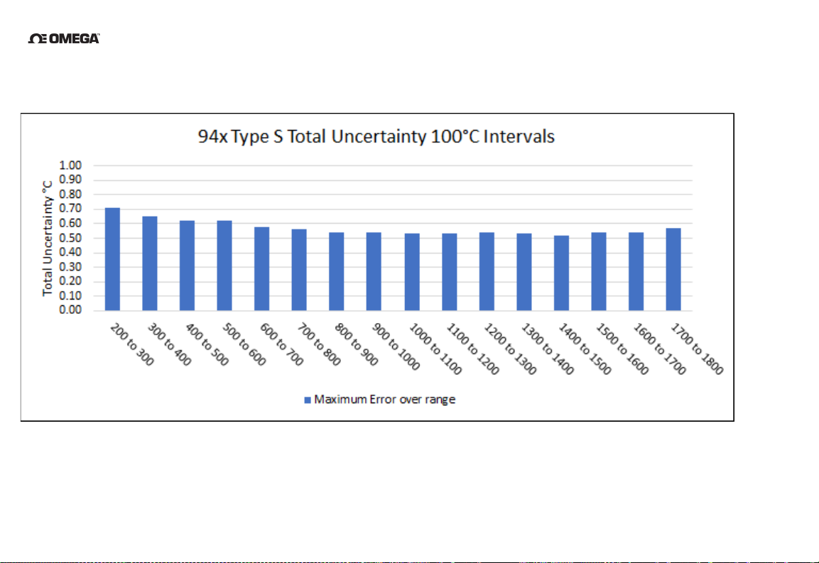
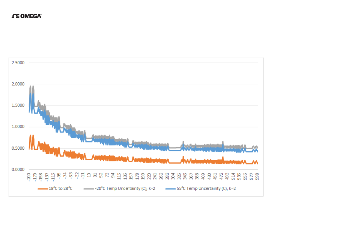
B. EXPANDED INSTRUMENT UNCERTAINTIES
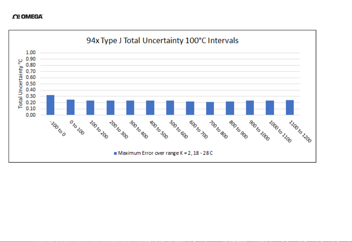
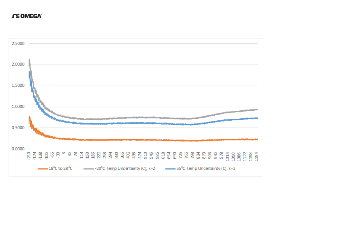
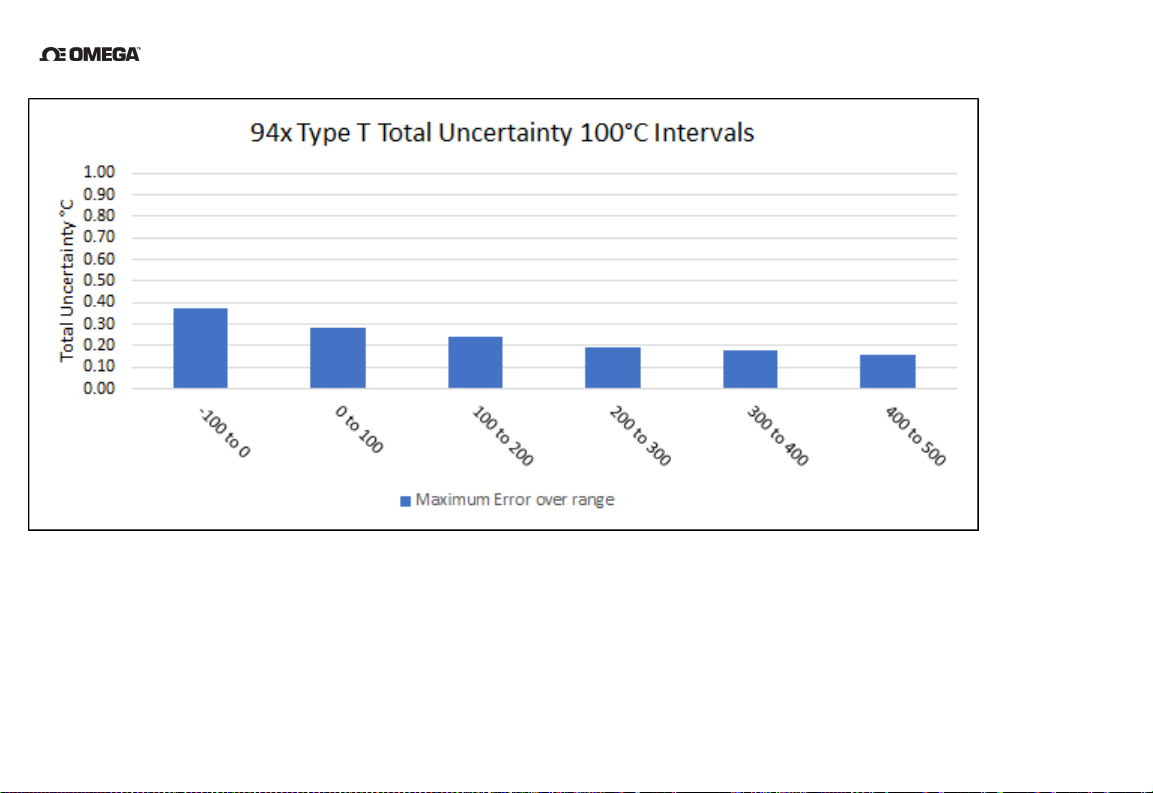
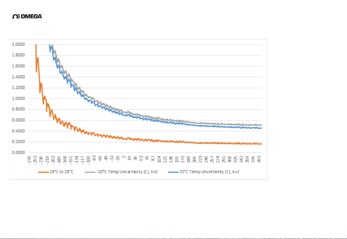
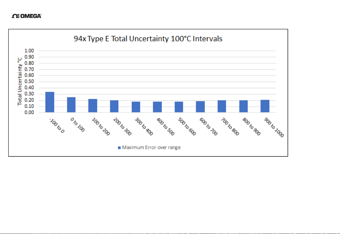
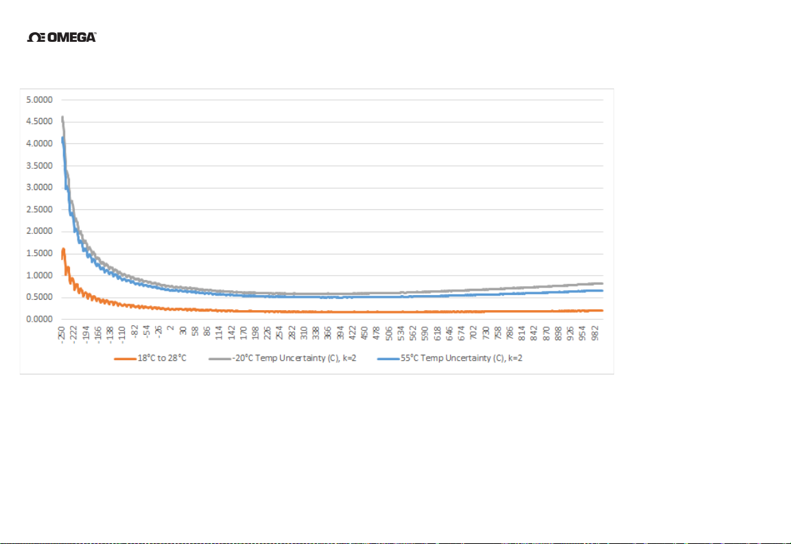
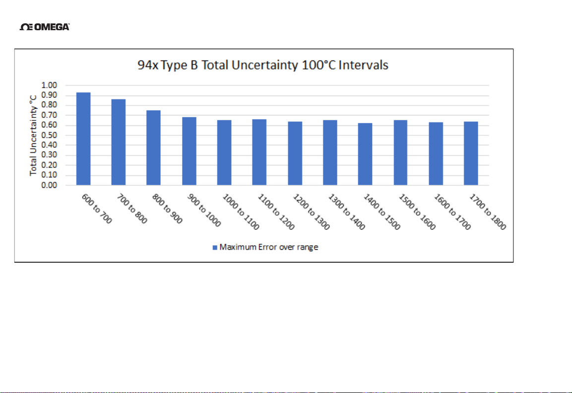
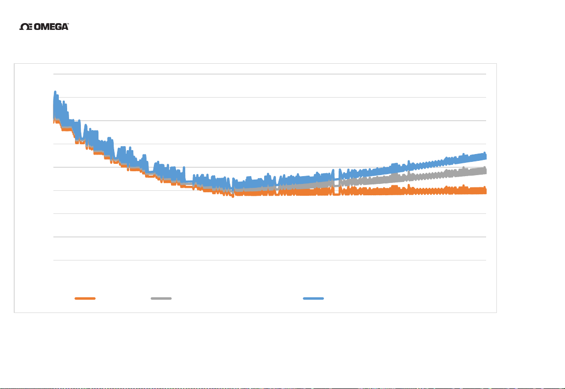
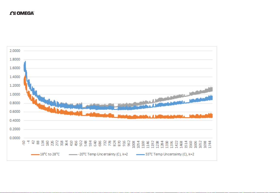
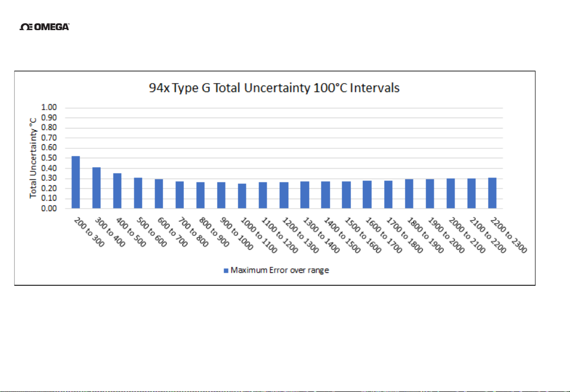
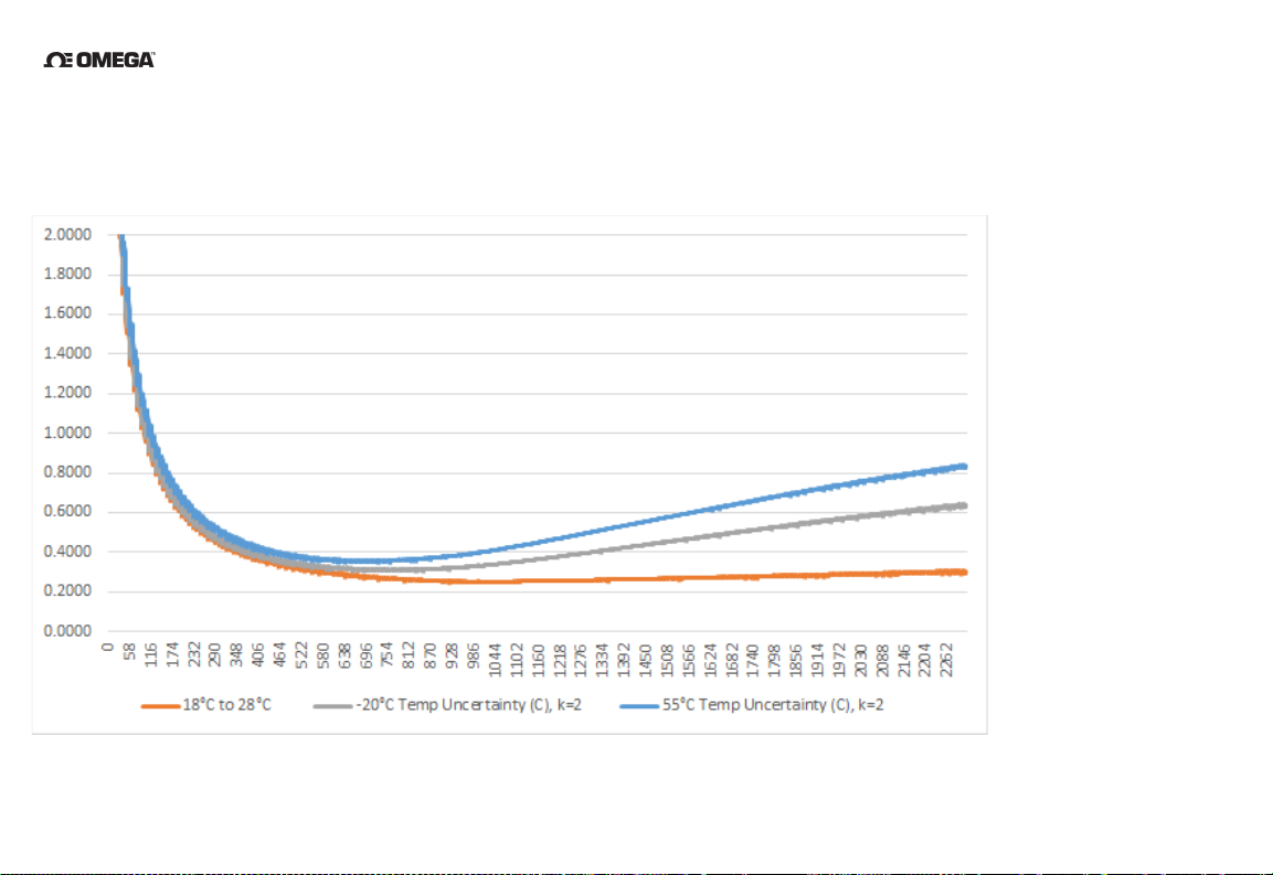
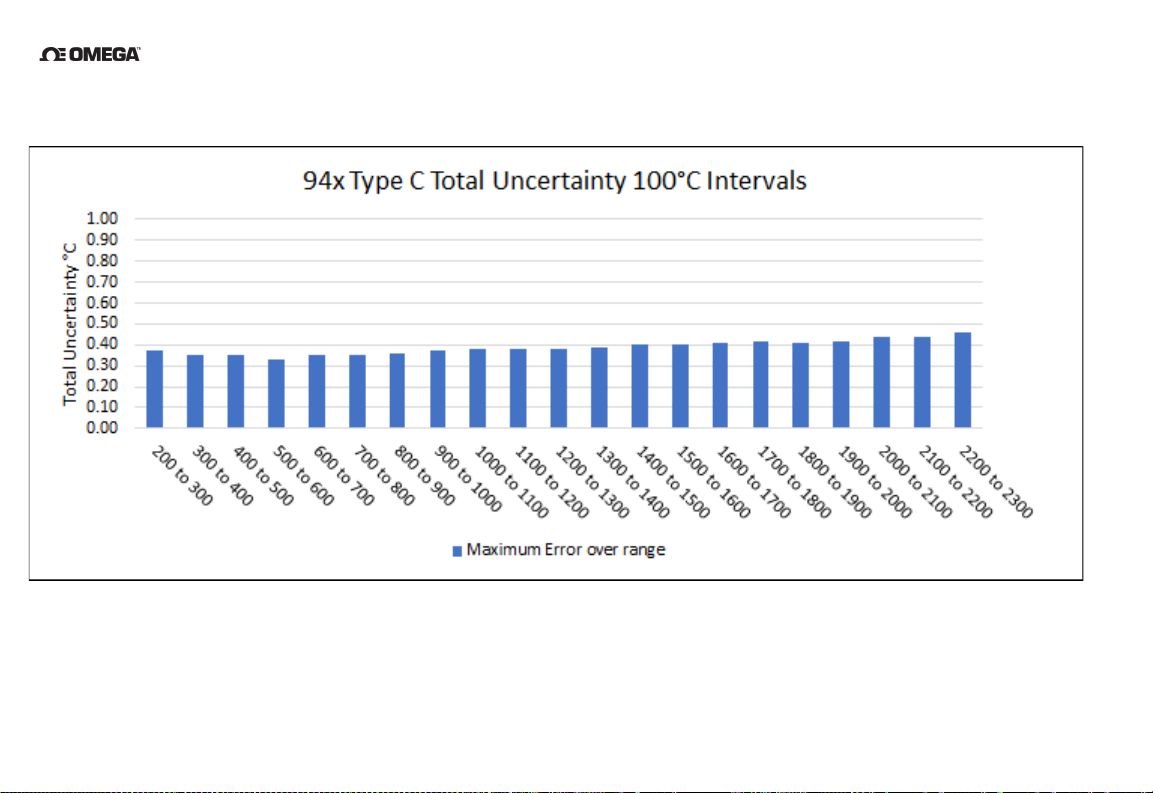
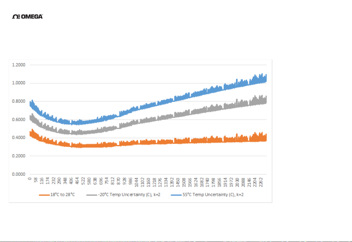
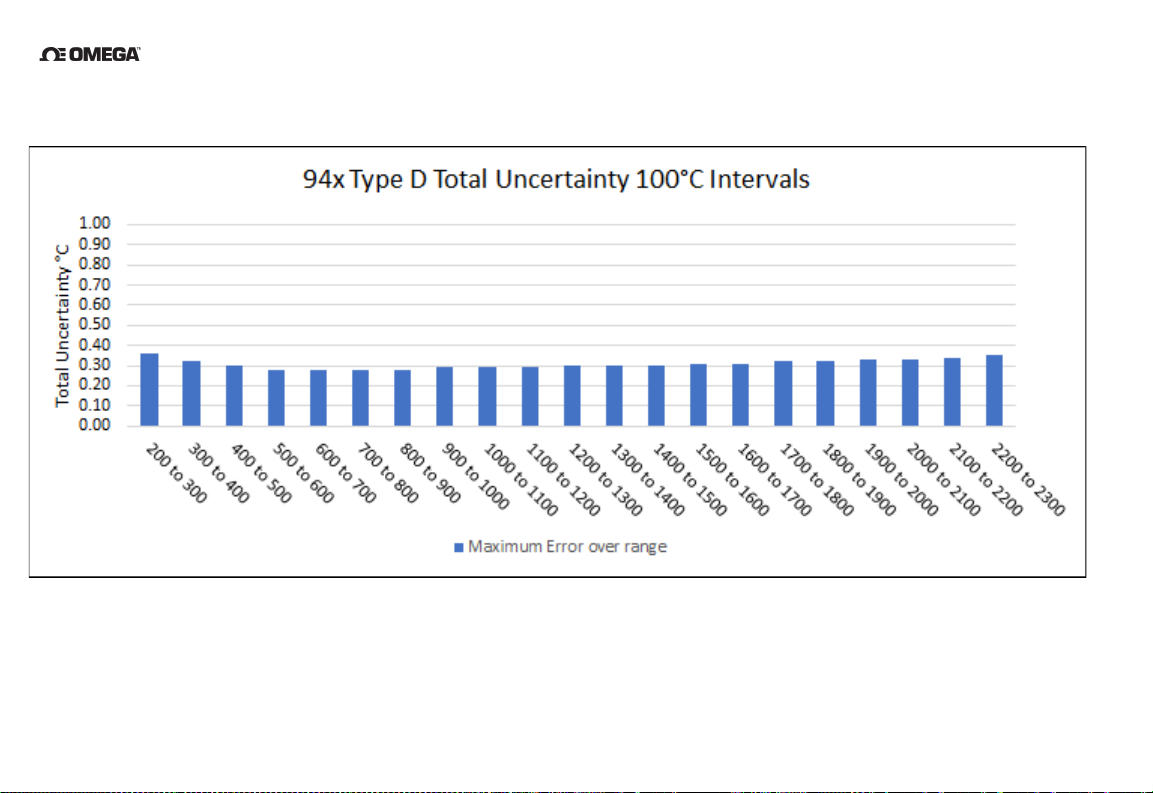
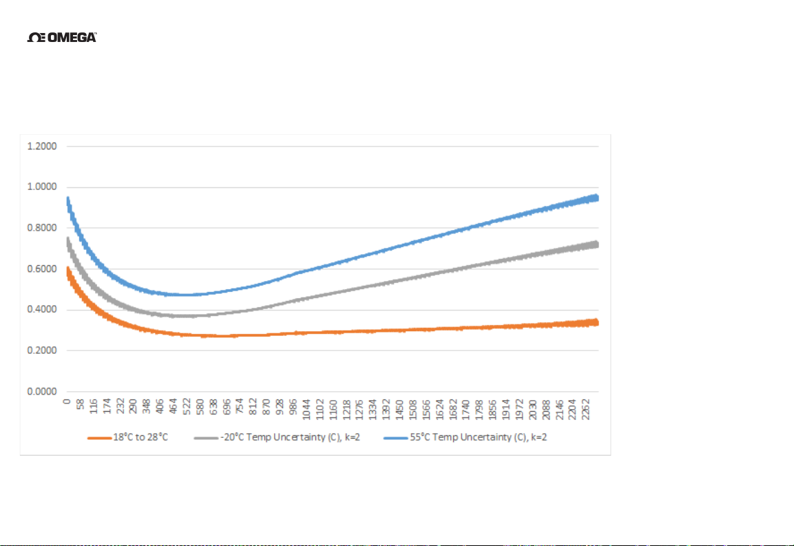
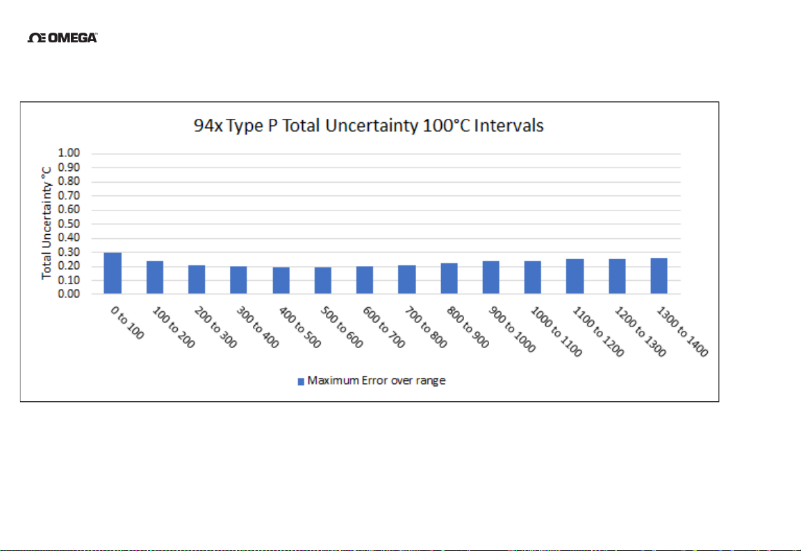
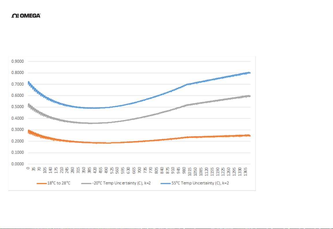
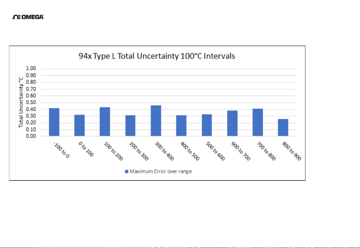
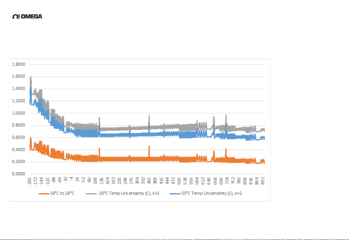
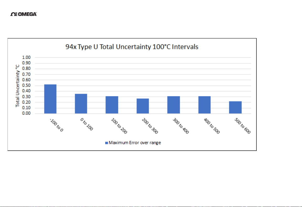
All uncertainty specifications for all charts are K = 2 unless otherwise noted.
B-i
Page 38
Appendices
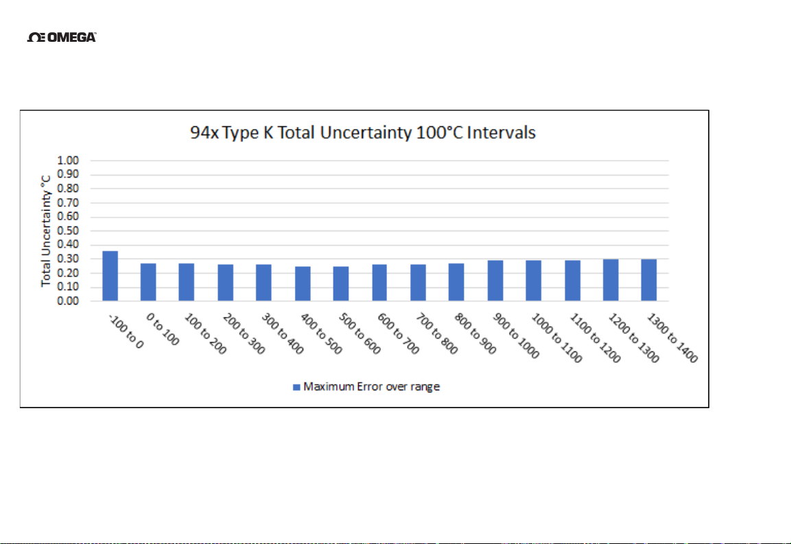
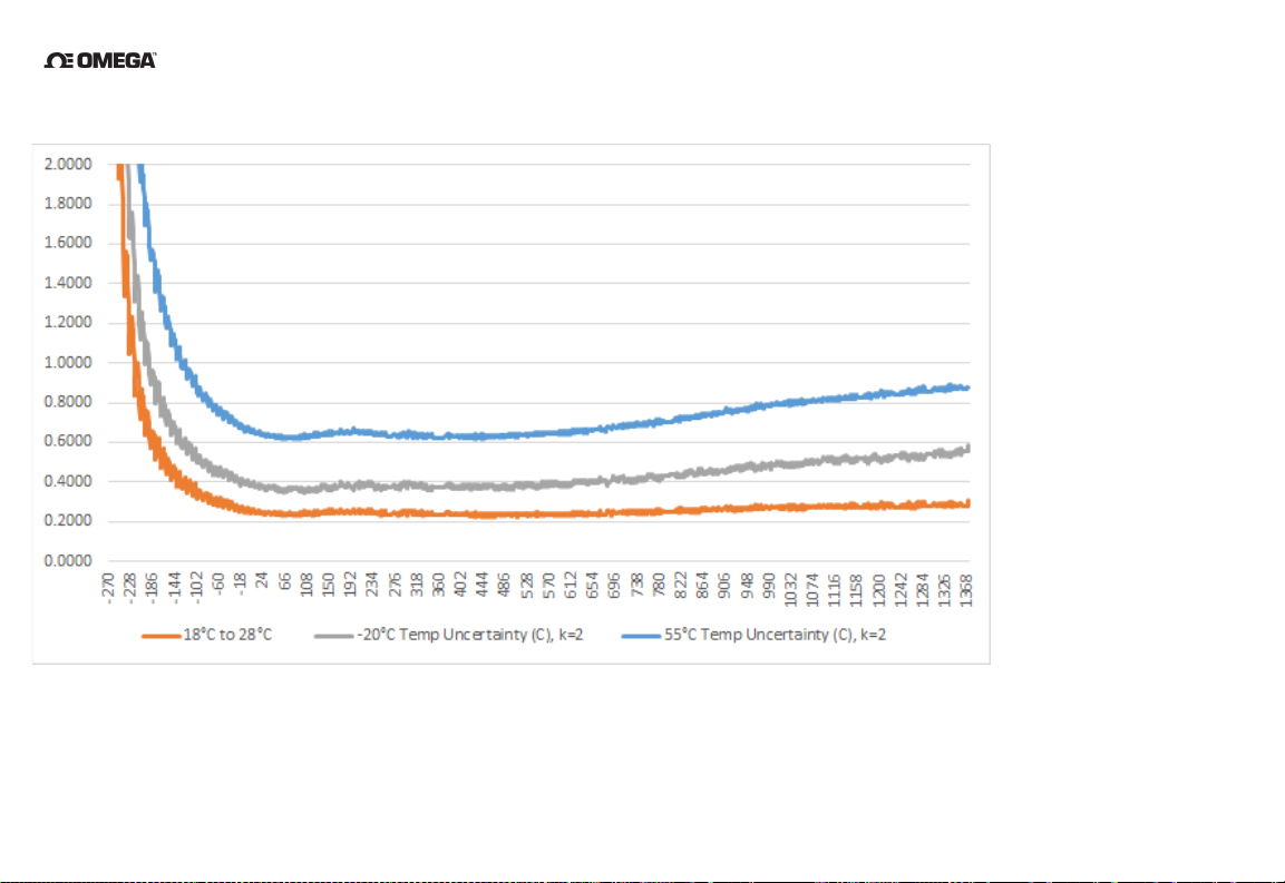
Following graphs show total uncertainty in degrees C (k=2), with operating condition between
18-28 °C unless otherwise noted.
B-ii
Page 39
Appendices
Thermocouple Type K
B-iii
Page 40
Appendices
B-iv
Page 41
Appendices
Thermocouple Type J
B-v
Page 42
Appendices
B-vi
Page 43
Appendices
Thermocouple Type T
B-vii
Page 44
Appendices
B-viii
Page 45
Appendices
Thermocouple Type E
B-ix
Page 46
Appendices
B-x
Page 47
Appendices
Thermocouple Type B
1.6000
1.4000
1.2000
1.0000
0.8000
0.6000
0.4000
0.2000
0.0000
400
436
472
508
544
580
18C - 28C -20C Temp Uncertainty (C), k=2 +55C Temp Uncertainty (C), k=2
616
652
688
724
760
796
832
868
904
940
976
1012
1048
1084
1120
1156
1192
1228
1264
1300
1336
1372
1408
1444
1480
1516
1552
1588
1624
1660
1696
1732
1768
1804
B-xi
Page 48
Appendices
B-xii
Page 49

Appendices
Thermocouple Type N
2.0000
1.8000
1.6000
1.4000
1.2000
1.0000
0.8000
0.6000
0.4000
0.2000
0.0000
-270
-229
-188
-147
-106
-65
175899
-24
140
181
222
263
304
345
386
427
468
509
550
591
632
673
714
755
796
837
878
919
960
1001
1042
1083
1124
1165
1206
1247
1288
18C - 28C -20 Temp Uncertainty (C), k=2 +55 Temp Uncertainty (C), k=2
B-xiii
Page 50
Appendices
B-xiv
Page 51
Appendices
Thermocouple Type R
B-xv
Page 52
Appendices
B-xvi
Page 53
Appendices
Thermocouple Type S
B-xvii
Page 54
Appendices
B-xviii
Page 55
Appendices
Thermocouple Type G
B-xix
Page 56
Appendices
B-xx
Page 57
Appendices
Thermocouple Type C
B-xxi
Page 58
Appendices
B-xxii
Page 59
Appendices
Thermocouple Type D
B-xxiii
Page 60
Appendices
B-xxiv
Page 61
Appendices
Thermocouple Type P
B-xxv
Page 62
Appendices
B-xxvi
Page 63
Appendices
Thermocouple Type L
B-xxvii
Page 64
Appendices
B-xxviii
Page 65
Appendices
Thermocouple Type U
B-xxix
Page 66
Appendices
PARAMETER
SETPOINT
MEASUREMENT RESULT
LIMITS OF ERROR
UNCERTAINTY
PASS/FAIL
L
LIMIT
U
LIMIT
Source DC Volts Channel 1
High Range -13mV to 83 mV
-13 mV
-13 mV
-13.00498 mV
-12.99502 mV
0.00194 mV
-10 mV
-10 mV
-10.00498 mV
-9.99502 mV
0.00192 mV
0 mV
0 mV
-0.0046 mV
0.0046 mV
0.0019 mV
5 mV
5 mV
4.99525 mV
5.00475 mV
0.00191 mV
20 mV
20 mV
19.99482 mV
20.00518 mV
0.00199 mV
80 mV
80 mV
79.99325 mV
80.00675 mV
0.00306 mV
83 mV
83 mV
82.99317 mV
83.00683 mV
0.00313 mV
Low Range -13mV to 33 mV
-13 mV
-13 mV
-13.00498 mV
-12.99502 mV
0.00194 mV
-10 mV
-10 mV
-10.00498 mV
-9.99502 mV
0.00192 mV
0 mV
0 mV
-0.0046 mV
0.0046 mV
0.0019 mV
10 mV
10 mV
9.99511 mV
10.00489 mV
0.00192 mV
30 mV
30 mV
29.99455 mV
10.00545 mV
0.0021 mV
33 mV
33 mV
32.99446 mV
30.00554 mV
0.00214 mV
PARAMETER
STANDARD
EASUREMENT
RESULT
TOLERANCE
LIMITS OF ERROR
UNCERTAINTY
PASS/FAIL
L
LIMIT
U
LIMIT
Measure DC Volts Channel 2 – The values entered in the “Standard” column below are the DMM readings for
each setpoint.
High Range -13mV to 83 mV
-13 mV
0.005 mV
0.00194 mV
-10 mV
0.005 mV
0.00192 mV
0 mV
0.0046 mV
0.0019 mV
5 mV
0.0048 mV
0.00191 mV
20 mV
0.0052 mV
0.00199 mV
80 mV
0.00675 mV
0.00306 mV
83 mV
0.00675 mV
0.00313 mV
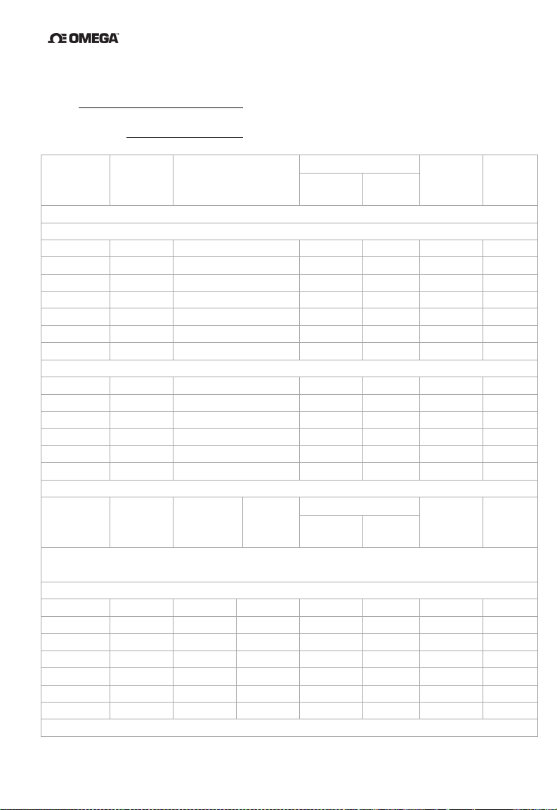
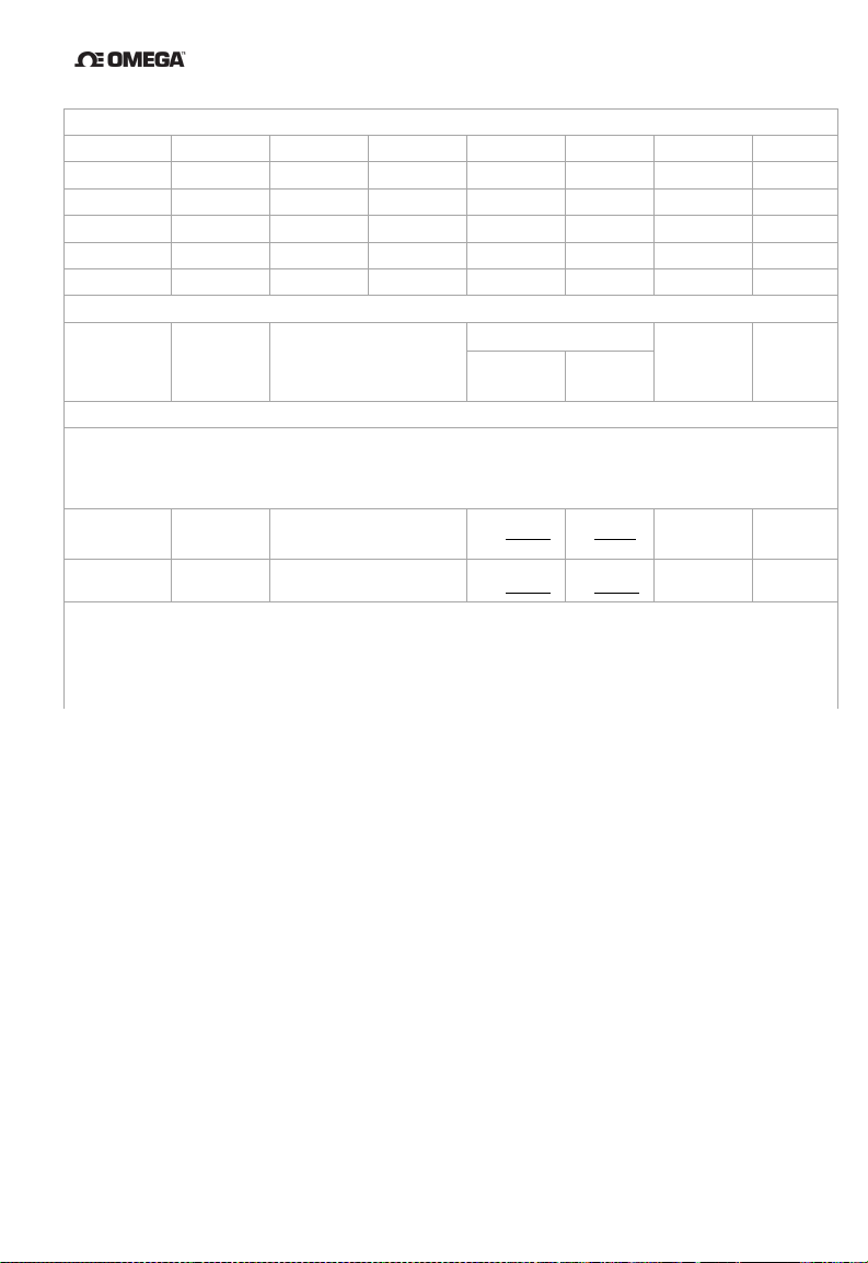
C. INSTRUMENT VERIFICATION DATA SHEET
Model:
Serial Number:
OWER
M
each setpoint. Calculate your Limits of Error by adding/subtracting the value noted in the “Tolerance” column for
OWER
PPER
PPER
EXPANDED
EXPANDED
1
1
C-i
Page 67
Appendices
Low Range -13mV to 33 mV
-13 mV
0.005 mV
0.00194 mV
-10 mV
0.005 mV
0.00192 mV
0 mV
0.0046 mV
0.0019 mV
10 mV
0.0049 mV
0.00192 mV
30 mV
0.00545 mV
0.0021 mV
33 mV
0.00545 mV
0.00214 mV
CHANNEL
STANDARD
MEASUREMENT RESULT
LIMITS OF ERROR
UNCERTAINTY
PASS/FAIL
L
LIMIT
U
LIMIT
Cold Junction Compensation
°C
°C
°C
°C
1
The estimated expanded uncertainties are based on a standard uncertainty multiplied by a coverage factor K=2,
OWER
Note: The values entered in the “Standard” column below are the Reference Thermometer readings for each
channel. Calculate your Limits of Error by: first add a factory determined offset of 0.06°C to the “Standard” value,
then add/subtract 0.11°C from the result to determine upper/lower limits. See section 4.2.1 paragraph 15 for an
example calculation.
1
2
providing a level of confidence of approximately 95%
2
Published temperature uncertainty values can only be achieved if the temperature of UUT is known within 40mK.
Customers performing CJC adjustments in their facility will need to calculate their own CJC uncertainty.
PPER
EXPANDED
2
C-ii
Page 68

WARRANTY/DISCLAIMER
OMEGA ENGINEERING, INC. warrants this unit to be free of defects in materials and
workmanship for a period of 37 months from date of purchase. OMEGA’s WARRANTY adds
an additional one (1) month grace period to the normal three (3) years product warranty to
cover handling and shipping time. This ensures that OMEGA’s customers receive maximum
coverage on each product.
If the unit malfunctions, it must be returned to the factory for evaluation. OMEGA’s Customer
Service Department will issue an Authorized Return (AR) number immediately upon phone
or written request. Upon examination by OMEGA, if the unit is found to be defective, it
will be repaired or replaced at no charge. OMEGA’s WARRANTY does not apply to defects
resulting from any action of the purchaser, including but not limited to mishandling, improper
interfacing, operation outside of design limits, improper repair, or unauthorized modification.
This WARRANTY is VOID if the unit shows evidence of having been tampered with or shows
evidence of having been damaged as a result of excessive corrosion; or current, heat, moisture
or vibration; improper specification; misapplication; misuse or other operating conditions
outside of OMEGA’s control. Components in which wear is not warranted, include but are not
limited to contact points, fuses, and triacs.
OMEGA is pleased to offer suggestions on the use of its various products. However,
OMEGA neither assumes responsibility for any omissions or errors nor assumes
liability for any damages that result from the use of its products in accordance
with information provided by OMEGA, either verbal or written. OMEGA warrants
only that the parts manufactured by the company will be as specified and free of
defects. OMEGA MAKES NO OTHER WARRANTIES OR REPRESENTATIONS OF ANY
KIND WHATSOEVER, EXPRESSED OR IMPLIED, EXCEPT THAT OF TITLE, AND ALL
IMPLIED WARRANTIES INCLUDING ANY WARRANTY OF MERCHANTABILITY AND
FITNESS FOR A PARTICULAR PURPOSE ARE HEREBY DISCLAIMED. LIMITATION
OF LIABILITY: The remedies of purchaser set forth herein are exclusive, and the
total liability of OMEGA with respect to this order, whether based on contract,
warranty, negligence, indemnification, strict liability or otherwise, shall not exceed
the purchase price of the component upon which liability is based. In no event shall
OMEGA be liable for consequential, incidental or special damages.
CONDITIONS: Equipment sold by OMEGA is not intended to be used, nor shall it be used: (1)
as a “Basic Component” under 10 CFR 21 (NRC), used in or with any nuclear installation or
activity; or (2) in medical applications or used on humans. Should any Product(s) be used in or
with any nuclear installation or activity, medical application, used on humans, or misused in
any way, OMEGA assumes no responsibility as set forth in our basic WARRANTY / DISCLAIMER
language, and, additionally, purchaser will indemnify OMEGA and hold OMEGA harmless from
any liability or damage whatsoever arising out of the use of the Product(s) in such a manner.
Direct all warranty and repair requests/inquiries to the OMEGA Customer Service Department.
RETURN REQUESTS/INQUIRIES
BEFORE RETURNING ANY PRODUCT(S) TO OMEGA, PURCHASER MUST OBTAIN AN
AUTHORIZED RETURN (AR) NUMBER FROM OMEGA’S CUSTOMER SERVICE DEPARTMENT
(IN ORDER TO AVOID PROCESSING DELAYS). The assigned AR number should then be
marked on the outside of the return package and on any correspondence.
The purchaser is responsible for shipping charges, freight, insurance and proper packaging to
prevent breakage in transit.
FOR WARRANTY RETURNS, please have
the following information available BEFORE
contacting OMEGA:
1. Purchase Order number under which
the product was PURCHASED,
2. Model and serial number of the product
under warranty, and
3. Repair instructions and/or specific
problems relative to the product.
OMEGA’s policy is to make running changes, not model changes, whenever an improvement is possible.
This affords our customers the latest in technology and engineering.
OMEGA is a registered trademark of OMEGA ENGINEERING, INC.
© Copyright 2019 OMEGA ENGINEERING, INC. All rights reserved. This document may not be copied, photocopied,
reproduced, translated, or reduced to any electronic medium or machine-readable form, in whole or in part, without
the prior written consent of OMEGA ENGINEERING, INC.
FOR NON-WARRANTY REPAIRS,
consult
OMEGA for current repair charges. Have the
following information available BEFORE
contacting OMEGA:
1. Purchase Order number to cover the
COST of the repair,
2. Model and serial number of the product, and
3. Repair instructions and/or specific problems
relative to the product.
Page 69

omega.com [email protected]
Servicing North America:
U.S.A. Omega Engineering, Inc.
Headquarters: Toll-Free: 1-800-826-6342 (USA & Canada only)
Customer Service: 1-800-622-2378 (USA & Canada only)
Engineering Service: 1-800-872-9436 (USA & Canada only)
Tel: (203) 359-1660 Fax: (203) 359-7700
e-mail: [email protected]
For Other Locations Visit omega.com/worldwide
M5725/0219CL940A Rev. A
The information contained in this document is believed to be correct, but OMEGA accepts no liability for any errors it contains,
and reserves the right to alter specifications without notice.
 Loading...