

Page 1

User’s Guide
Shop online at
omega.com
e-mail: [email protected]
For latest product manuals:
www.omegamanual.info
sm
CL543B
Automated
Thermocouple & RTD Calibrator
Page 2

omega.com [email protected]
U.S.A.:
Stamford, CT 06907-0047 USA
For Other Locations Visit omega.com/worldwide
Servicing North America:
Omega Engineering, Inc., One Omega Drive, P.O. Box 4047
Toll-Free: 1-800-826-6342 (USA & Canada only)
Customer Service: 1-800-622-2378 (USA & Canada only)
Engineering Service: 1-800-872-9436 (USA & Canada only)
Tel: (203) 359-1660 Fax: (203) 359-7700
e-mail: [email protected]
The information contained in this document is believed to be correct, but OMEGA
accepts no liability for any errors it contains, and reserves the right to alter
specifications without notice.
Page 3
CL543B
Automated
Thermocouple
& RTD
Calibrator
CL543B
Automated
Thermocouple
& RTD
Calibrator
Page 4

Contents
General Operations
Connections ............................................................................ 4
Accessories
Carrying Case, Boot................................................................6
Changing Batteries & Storing EZ-CHECK Outputs
Basic Operation
Switches & Knobs ................................................................8-9
MAIN Menus - Functions, Units & Ranges
FEATURE Menu - Stepping & Ramping / Auto Off
FEATURE Menu - Stepping & Ramping / Backlight
Functions and Hookup Diagrams
Millivolt
Source mV; Read mV ...................................................... 14,15
Thermocouple
Source T/C & Read T/C Sensors ..................................... 16,17
Resistance
Source Resistance, Read Resistance.............................. 18,19
RTD
Source RTD & Read RTD Sensors.................................20, 21
Troubleshooting RTD Instruments
Troubleshooting RTD Sensors
Specifications
General ............................................................................26-29
Thermocouple Ranges & Accuracies...............................30-33
RTD Ranges & Accuracies
Warranty
Additional Information & Warranty ................................... 36-37
............................................................................. 5
...................... 10-11
........................................ 22
.............................................. 24
..............................................34-35
................ 7
............... 12
............. 13
Page 5

General Information
Calibrate all your T/C & RTD Instruments
• Easy to use
With the Omega CL543B you can check and
calibrate all your thermocouple and RTD
instruments and measure temperature sensors.
• Take it into the shop, plant or field
Carry it without worry - it comes protected with a
rubber boot and rugged, low profile switches.
Easy to operate even in the dark areas of the
plant with the backlit display.
Calibrate T/C instruments to 0.1 & 0.01 °F & °C
•
The Omega CL543B works with the
thermocouples you use including types J, K, T,
E, R, S, B, N, G, C, D, L (J-DIN), U (T-DIN) and
P (Platinel II). Or calibrate from -13.0000 to
+80.0000 mV.
• Calibrate RTD instruments to 0.1 & 0.01 °F & °C
Stop carrying around a decade box and RTD
resistance tables. The CL543B works with the
RTDs you use including Platinum 10, 50, 100,
200, 500 & 1000 Ohm (alpha = 3850), Platinum
100 Ohm (alpha = 3902, 3916, 3926), Copper
10 & 50 Ohm, and Nickel 120 Ohm. Or calibrate
from 0.000 to 400.000 and 0.00 to 4000.00
Ohms.
Page 1
Page 6

• Fast calibration with automatic output
stepping
Easily set any value quickly to within 0.1° or 0.01°
with the adjustable digital potentiometer “DIAL”
plus store any three temperatures for instant
recall with the EZ-CHECK™ switch. Choose
between 2, 3, 5, 11 steps and ramp to
automatically increment the output in 100%, 50%,
25%, 10% or 5% of span. Select step time from
5, 6, 7, 8, 9, 10, 15, 20, 25, 30 & 60 seconds.
• Compatible with ALL process instruments
No competitor’s calibrator is compatible with as
many process instruments! Connect directly to the
temperature inputs of transmitters, PLCs, DCS &
multichannel recorders to verify their outputs or
displays. RTD simulation works with older
instruments with fixed excitation currents and newer
multichannel instruments that switch the excitation
current between input channels.
• Perform Heat Treating Uniformity Surveys and
System Accuracy Tests
The Omega CL543B meets or exceeds the
requirement of AMS 2750 as a Field Test
Instrument.
• Measure thermocouple & RTD sensors
The Omega CL543B measures probes to 0.1 or
0.01 °C or °F. Secondary display shows the
millivolt or resistance value corresponding to the
sensor temperature. For T/Cs the cold junction
Page 2
Page 7

temperature measured by the calibrator. For
RTDs the fixed or pulsed sensor current
outputted by the measuring instrument is
measured by the calibrator.
• Find problems with troubleshooting tools
Open thermocouples and thermocouples that
have high resistance indicating impending failure
are indicated by OPEN TC on the display.
Troubleshoot RTD sensor connections and find
broken wires with patented technology. Connect
your two, three or four wire RTDs and the
Omega CL543B automatically detects the
connections.
• Calibration Lab Accurate & Stable
The internal cold junction thermistor is accurate
to ±0.05°C and is traceable to NIST. The sensor
is thermally bonded to an isothermal mass
which includes brass blocks with screw
terminals for connection of bare thermocouple
wires along with a miniature thermocouple
connector for fast connections. The circuitry
uses an extremely stable voltage reference and
low drift components which make the CL543B
more accurate than most other handheld and
bench top thermocouple calibrators.
Become a troubleshooting technician with
Patented Diagnostic Technology - Available only
with Omega Calibrators!
Page 3
Page 8

Connections
Simulating or reading thermocouples requires the use of
thermocouple or extension grade thermocouple wire.
Plug thermocouple wires into the miniature jack or place bare
thermocouple wires onto the brass block under the screws.
The Omega CL543B has two banana jacks (1+ & 2-) mounted
in the top end of the housing. These are not temperature
compensated and are to be used only for millivolt signals or
thermocouple signals with the cold junction turned off.
Simulating or reading RTDs uses copper wire.
Plug 2, 3 or 4 wires into the corresponding jacks on the
calibrator. For RTD source the Omega CL543B simulates the (+)
RTD from jacks 1 & 4 and the (-) RTD from jacks 2 & 3.
When reading an RTD sensor the Omega CL543B uses
patented circuitry to automatically detect if 2, 3 or 4 wires are
connected. This is helpful to troubleshoot sensor connection
(see Troubleshooting an RTD Sensor).
Page 4
Page 9

Accessories
INCLUDED:
Four “AA” Alkaline batteries, Certificate of Calibration
Evolution Hands Free Carrying Case
Dark Blue Rubber Boot
Test Leads - one pair with
banana plug & alligator clips
Evolution RTD Wire Kit
2 Red & 2 Black Leads with
Banana Plugs & Spade Lugs
OPTIONAL:
Ni-MH 1 Hour Charger with 4 Ni-MH AA
Batteries (100-120 V AC input for North America Only)
T/C Wire Kit 1* for Types J, K, T & E
T/C Wire Kit 2* for Types B, R/S & N
*Three feet (1 meter) of T/C extension wire, stripped on one
end with a miniature T/C male connector on the other end.
Page 5
Page 10

Operating Instructions
FIELD & BENCH USE
Omega CL543B comes with a carrying case designed for
hands-free operation and a rubber boot with a built-in tilt stand.
The Omega CL543B is held in the case by elastic straps for use
with the carrying case open. The tilt stand is easily raised by
pulling the stand until it locks into place.
Page 6
Page 11

Operating Instructions
CHANGING BATTERIES
Low battery is indicated by a battery symbol on the display.
Approximately one to four hours of typical operation remain before
the Omega CL543B will automatically turn off. To change the
batteries remove the rubber boot and remove the battery door
from the back of the unit by sliding the door downward. This allows
access to the battery compartment. Replace with four (4) “AA” 1.5V
batteries being careful to check the polarity. Replace the battery
door and replace the boot. All stored configuration options (T/C
Type, EZ-CHECK Memories, etc.) are reset to factory settings
when the batteries are removed.
Note: Alkaline batteries are supplied and recommended for
typical battery life and performance. Optional rechargeable
batteries (charged externally) are available.
STORING HI and LO EZ-CHECK Source Outputs
Speed up your calibration by storing Span & Zero output setting
for instant recall with the EZ-CHECK switch.
1) Store your high (SPAN) output temperature by moving the
EZ-CHECK switch to the HI position and turning the EZ-Dial
knob until the desired output value is on the display. Press
and hold the EZ-Dial knob until STORED appears to store
the value. Release the EZ-Dial knob.
2) Store your low (ZERO) output value by moving the EZ-CHECK
switch to the LO position and turning the EZ-Dial knob until
the desired output value is on the display. Press and hold the
EZ-Dial knob until STORED appears to store the value.
Release the EZ-Dial knob.
3) Instantly output your SPAN and ZERO output settings by
moving the EZ-CHECK switch between HI and LO. You may
also select any third output setting (such as mid-range) using
the SET position on the EZ-CHECK switch.
Page 7
Page 12
Operating Instructions
Basic Operation
+
-
22.4°C
T/C
43.307mV
1052.50
HI
Automated RTD &
Thermocouple Calibrator
Pt 10, 50, 100, 200, 500 & 1000Ω
Cu 10 & 50Ω · Ni 120Ω
J · T · E · K · R · S · B · N · G · C · D · L· U · P · mV
HI
SET
LO
OVERLOAD
°C
TYPE K
SOURCE
MAX
READ
OFF
MIN
READ
Double Click
Menu
Push & Turn
for
Fast Dialing
Push & Hold
to
Store/Step
q
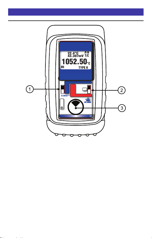
EZ-CHECK™ SWITCH
SOURCE: Instantly output two preset settings by moving the
EZ-CHECK™ switch to the “LO” position or “HI” position.
three point checks select the “SET” position. The CL543B will
remember the last “SET” value, even with the power off.
These values can easily be changed to suit the calibration requirements.
The values stored in the HI and LO positions are also used for Auto
Stepping.
For fast
READ: Slide the switch to the SET position. The Omega CL543B will
display the current reading from the sensor or device being measured.
Slide the switch to MAX and the highest value measured since turn-on
or reset will be displayed; slide the switch to MIN and the lowest value
measured since turn-on or reset will be displayed.
Page 8
Page 13

Operating Instructions
Basic Operation
w SOURCE/OFF/READ Switch
Select “SOURCE” to output mV, T/C, Ω or RTD.
Select “READ” to read mV, T/C, Ω or RTD.
Select “OFF” to turn off the CL543B.
e EZ-DIAL™ KNOB
SOURCE: Turn the knob to adjust the output level. Turn clockwise to
increase the output, counter clockwise to decrease the output in one
least significant digit step at a time. Push down and turn the
EZ-DIAL knob for faster dialing.
Press and hold the knob for two seconds to store desired
EZ-Check™ HI/LO points in SOURCE mode. Continue to press and
hold the knob for two more seconds to start the automatic ramping.
READ: Press and hold to transfer the current temperature into
the EZ-Check™ MIN/MAX points. This clears the MIN/MAX
readings which will update as the input value changes.
SELECTING FUNCTIONS
The EZ-DIAL knob is used to setup the Omega CL543B to
match the instrument to be calibrated or signal to be measured.
Each time you turn on the CL543B the LCD displays the following screen for about 1 second followed by operating in the function used the last time it was operated.
DOUBLE CLICK
EZ-DIAL KNOB
FOR CONFIGURATION
Double Click the EZ-DIAL knob to change the function of the
calibrator and to select ranges, units and other user settings.
Each function (mV, T/C, Ohms, RTD) has up to three pages of
menus. The first menu page has settings for the function and the
last menu page has settings for STEPPING, AUTO OFF and
BACKLIGHT. Settings are remembered even with the power off
but are reset when the batteries are changed.
Page 9
Page 14
Operating Instructions
Double Click Menus - MAIN Page
Double click the EZ-DIAL knob to access the Double Click
Menus. Shown are the MAIN menus for each function. Turn the
knob to scroll thru the menus and press the knob to select. Default
values are in black and available choices are shown in grey.
Source V
>EXIT (1/3)
FUNCTION V
RANGE 80mV
>EXIT (1/3)
FUNCTION V
RANGE 80mV
Read V
Source & Read Thermocouples
>EXIT (1/3)
FUNCTION T/C
UNITS °C °F
T/C TYPE J K E T R S B N L U G C D P
COLD JUNC ON OFF
Source Ohms
>EXIT (1/3)
FUNCTION OHMS
RANGE 400Ω 4000Ω
>EXIT (1/3)
FUNCTION OHMS
RANGE 400Ω 4000Ω
Read Ohms
Source RTD
>EXIT (1/3)
FUNCTION RTD
UNITS °C °F
RTD Pt 100 a=3850 [*RTD Types - See Read RTD]
Read RTD
>EXIT (1/3)
FUNCTION RTD
UNITS °C °F
RTD Pt 100 a=3850,
Pt 1000 a=3850, Pt 100 a=3902, Pt 10 0 a=3916,
Pt 100 a=3926, Cu 10 a=4274, Cu 50 a=4280, Ni 120 a=6720
Pt 10 a=3850, Pt 50 a=3850
Pt 200 a=3850, Pt 500 a=3850,
Page 10
Page 15
Operating Instructions
Double Click Menu - DISPLAY Page
Double click the e DIAL KNOB at any time the unit is on and
then turn the e DIAL KNOB to move to the second menu page
so the word DISPLAY appears at the top of the menu.
Turn the e DIAL KNOB to move through the menu. Press the e
DIAL KNOB to toggle between LOW and HIGH or OFF and ON.
LOW resolution is 0.001 mV, 0.01Ω in 400Ω Range, 0.1Ω in
4000Ω Range and 0.1° for T/C & RTD. HIGH resolution is 0.0001
mV, 0.001Ω in 400Ω Range, 0.01Ω in 4000Ω Range and 0.01° for
T/C & RTD.
> EXIT (2/3)
RESOLUTION LOW HIGH
DISPLAY [Thermocouple]
> EXIT (2/3)
RESOLUTION LOW HIGH
DISPLAY mV OFF ON
DISPLAY CJ OFF ON [Cold Junction Temperature]
> EXIT (2/3)
RESOLUTION LOW HIGH
SENSOR mA* OFF ON
DISPLAY [RTD]
> EXIT (2/3)
RESOLUTION LOW HIGH
DISPLAY OHMS OFF ON
SENSOR mA* OFF ON
* SENSOR mA is only available when sourcing Ohms & RTD.
EXIT MENU - exits this menu immediately and saves any
changes. Menu will automatically exit after 15 seconds of
inactivity. Settings are remembered even with the power off.
DISPLAY [Millivolts]
DISPLAY [Ohms]
Page 11
Page 16

Operating Instructions
Double Click Menu - FEATURES
To change the Automatic Stepping settings
Double click the e DIAL KNOB at any time the unit is on and
the following typical display (will be different for each FUNCTION)
will appear for 15 seconds:
MAIN
> EXIT (1/3)
FUNCTION T/C
UNITS °C
T/C TYPE J
COLD JUNC ON
Turn the
word FEATURES appears at the top of the menu.
Turn the e DIAL KNOB to move through the menu. Press the e
DIAL KNOB to toggle between OFF and ON or to change the
STEPS/RAMP and the STEP/RAMP TIME settings. These
settings are remembered even with the power off.
EXIT MENU - exits this menu immediately and saves any
changes. Menu will automatically exit after 15 seconds of
inactivity.
e DIAL KNOB to move to the third menu page so the
FEATURES
> EXIT (3/3)
AUTO OFF ON
BACKLIGHT ON
STEPS/RAMP 3
STEP/RAMP TIME 5
AUTO OFF - If AUTO OFF is ON, the unit will turn off after 30
minutes of inactivity to save battery life. If AUTO OFF is OFF the
unit will stay on until the POWER SWITCH is moved to the off
position.
Page 12
Page 17

Operating Instructions
Double Click Menu - FEATURES
STEPS/RAMP - pressing the knob will cycle through 2, 3, 5, 11
and RAMP. The endpoints of the steps or ramp are based on the
values stored in the HI and LO EZ-CHECK outputs.
2 steps will automatically switch between the values stored in
the HI & LO EZ-CHECK (0 & 100%).
3 steps between the HI, Midpoint and LO EZ-CHECK (0, 50
& 100%).
5 steps between the HI and LO EZ-CHECK in 25%
increments (0, 25, 50, 75 & 100%).
11 steps between the HI and LO EZ-CHECK in 10%
increments (0, 10, 20...80, 90 &100%).
RAMP continuously ramps up and down between the HI and
LO EZ-CHECK outputs.
STEP/RAMP TIME - pressing the knob will cycle through 5, 6, 7,
8, 9, 10, 15, 20, 25, 30 and 60 seconds.
To start the Automatic Stepping
Start automatic stepping or ramping by placing the EZ-CHECK
Switch into the HI or LO position then press and hold the e
DIAL KNOB for 6 seconds (the word STORE will appear on the
display after 3 seconds and continue to press the EZ-DIAL
KNOB) until the word STEPPING appears on the display. The
word STEPPING will appear on the display anytime the selected
automatic function is running. Stop the stepping by again
pressing and holding the
e DIAL KNOB for 3 seconds.
BACKLIGHT - If BACKLIGHT is ON the backlight will light all the
time the unit is powered up. For maximum battery life turn the
backlight off when using the calibrator in areas with enough
ambient light to read the display.
Page 13
Page 18
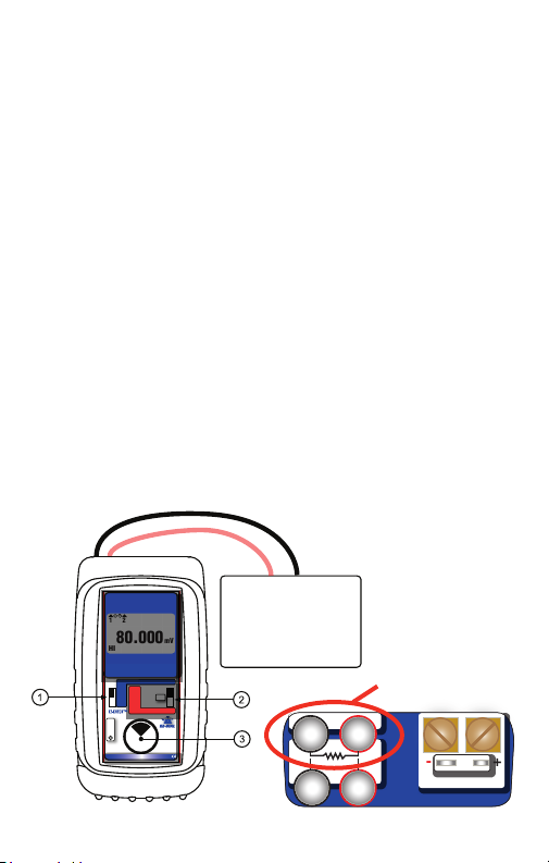
SOURCE mV
Choose this function to provide an output from -13.000 to 80.000
mV in LOW resolution and -13.0000 to 80.0000 mV in HIGH
resolution. The source current is a nominal 12 mA to provide the
driving power to analog thermocouple meters.
Move the power switch
w to SOURCE then Double Click the
EZ-DIAL knob to get into the Menu. Turn the knob to scroll
through the settings and press the knob to make your selection.
Select V for the FUNCTION.
Connect the output leads of the Omega CL543B to the inputs of
the device being calibrated, making sure to check polarity. Red
lead to the plus (+) input and black lead to the minus (-) input.
Instantly output your SPAN and ZERO output settings by moving
the EZ-CHECK switch between HI and LO. You may also select
any third output setting (such as mid-range) using the SET
position on the EZ-CHECK switch. The output is adjusted in
0.001 mV increments in LOW and 0.0001 increments in HIGH
resolution by turning the knob
e. Press and turn the knob for
faster dialing with 0.1 mV increments in both LOW and HIGH
resolution.
Voltage Receiver Input
+
-
1 2
80.000
HI
Automated RTD &
Thermocouple Calibrator
Pt 10, 50, 100, 200, 500 & 1000Ω
Cu 10 & 50Ω · Ni 120Ω
J · T · E · K · R · S · B · N · G · C · D · L· U · P · mV
MAX
HI
READ
SET
OFF
MIN
LO
Double Click
OVERLOAD
mV
SOURCE
READ
Menu
Push & Turn
for
Fast Dialing
Push & Hold
to
Store/Step
Controller
Transmitter
Computer
Logger
DCS
-
2
3
mV
RTD
mV Source
+
1
4
Ω
+-
T/C
Page 14
Page 19
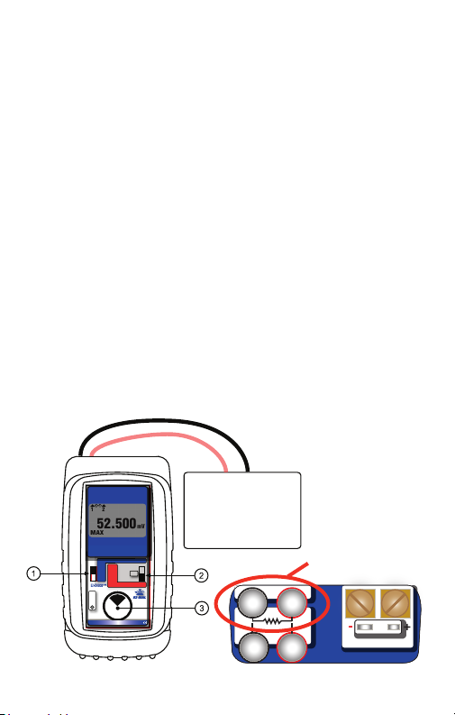
Read mV
Choose this function to measure from -13.000 to 80.000 mV in
LOW resolution and -13.0000 to 80.0000 mV in HIGH resolution.
Move the power switch
w to READ then Double Click the
EZ-DIAL knob to get into the Menu. Turn the knob to scroll
through the settings and press the knob to make your selection.
Select V for the FUNCTION.
Connect the red input lead (+) of the Omega CL543B to the
more positive point and the black input lead (-) to the more
negative point.
Signals above the maximum scale are limited by protection
circuitry with “OVER RANGE” flashed on the display and the red
OVERLOAD LED lit.
The Omega CL543B measures the input signal and constantly
updates the display with the current reading. Move the
EZ-CHECK switch
MIN to see the lowest reading. Press and hold the knob
q to MAX to see the highest reading and to
e to
clear the MAX and MIN readings.
+
-
1 2
52.500
MAX
Automated RTD &
Thermocouple Calibrator
Pt 10, 50, 100, 200, 500 & 1000Ω
Cu 10 & 50Ω · Ni 120Ω
J · T · E · K · R · S · B · N · G · C · D · L· U · P · mV
SOURCE
MAX
HI
READ
SET
OFF
MIN
LO
Double Click
OVERLOAD
Push & Turn
Fast Dialing
Push & Hold
Voltage Output Signal
Controller
Transmitter
mV
Power Supply
mV Read
READ
Menu
for
to
Store/Step
-
2
3
mV
RTD
+
1
4
Ω
+-
T/C
Page 15
Page 20
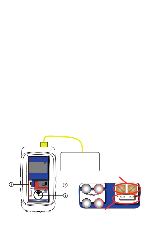
Source Thermocouple
Choose this function to provide a simulated thermocouple signal
into controllers, temperature transmitters, indicators or any input
devices that measure thermocouple sensors.
Move the power switch
w to SOURCE then Double Click the
EZ-DIAL knob to get into the Menu. Turn the knob to scroll
through the settings and press the knob to make your selection.
Select T/C for the FUNCTION, °F or °C for the UNITS, T/C Type
(J, K, E, T, R, S, B, N, L (J-DIN), U (T-DIN), G, C, D or P (Platinel
II)) and internal COLD JUNC ON or OFF (ON is the default).
Connect the Omega CL543B to the inputs of the device being
calibrated using the proper type of thermocouple wire via the
miniature thermocouple socket or place bare thermocouple
leads under the brass screws.
Instantly output your SPAN and ZERO output settings by moving
the EZ-CHECK switch between HI and LO. You may also select
any third output setting (such as mid-range) using the SET
position on the EZ-CHECK switch. The output is adjusted in 0.1°
increments in LOW and 0.01° increments in HIGH resolution by
turning the knob
e. Press and turn the knob for faster dialing
with 10° increments in both LOW and HIGH resolution.
Thermocouple Wire
Instrument with T/C Input
Controller
Temperature Transmitter
+
-
22.4°C
T/C
43.307mV
1052.50
HI
TYPE K
Automated RTD &
Thermocouple Calibrator
Pt 10, 50, 100, 200, 500 & 1000Ω
Cu 10 & 50Ω · Ni 120Ω
J · T · E · K · R · S · B · N · G · C · D · L· U · P · mV
MAX
HI
READ
SET
OFF
MIN
LO
Double Click
OVERLOAD
°C
SOURCE
READ
Menu
Push & Turn
for
Fast Dialing
Push & Hold
to
Store/Step
Temperature Indicator
Temperature Trip or Alarm
mV
-
2
RTD
3
Ω
Bare thermocouple wires
+
1
4
T/C
+-
Miniature thermocouple connectors
Page 16
Page 21
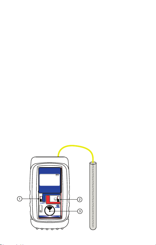
Read Thermocouple Sensors
Choose this function to measure temperatures with a
thermocouple probe, sensor or any devices that output a
thermocouple signal.
Move the power switch
w to READ then Double Click the
EZ-DIAL knob to get into the Double Click Menu. Turn the knob
to scroll through the settings and press the knob to make your
selection. Select T/C for the FUNCTION, °F or °C for the UNITS,
T/C Type (J, K, E, T, R, S, B, N, L (J-DIN), U (T-DIN), G, C, D or
P (Platinel II)) and COLD JUNC ON or OFF (ON is the default).
Connect the Omega CL543B to the inputs of the device being
calibrated using the proper type of thermocouple wire via the
miniature thermocouple socket or place bare thermocouple
leads under the brass screws. If no sensor is connected, a wire
is broken or the sensor is burned out, OPEN TC will appear on
the display. Signals above the maximum scale are limited by
protection circuitry with “OVER RANGE” on the display.
The CL543B measures the input signal and constantly updates
the display with the current reading. Move the EZ-CHECK switch
q to MAX to see the highest reading and to MIN to see the
lowest reading. Press and hold the knob e to clear the MAX and
MIN readings.
23.7°C
21.710mV
525.00
MIN
Automated RTD &
Thermocouple Calibrator
Pt 10, 50, 100, 200, 500 & 1000Ω
Cu 10 & 50Ω · Ni 120Ω
J · T · E · K · R · S · B · N · G · C · D · L· U · P · mV
HI
SET
LO
OVERLOAD
Thermocouple
Wire
+
-
T/C
°C
TYPE K
SOURCE
MAX
READ
OFF
MIN
READ
Double Click
Menu
Push & Turn
for
Fast Dialing
Push & Hold
to
Store/Step
Page 17
Page 22
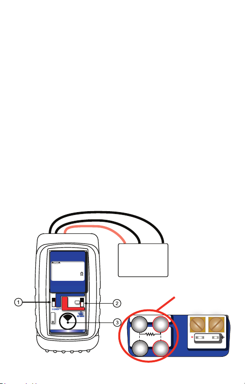
Source Resistance
Choose this function to provide a simulated resistance into any
device that measures resistance.
Move the power switch w to SOURCE then Double Click the
EZ-DIAL knob to get into the Menu. Turn the knob to scroll
through the settings and press the knob to make your selection.
Select OHMS for the FUNCTION, 400Ω or 4000Ω for the RANGE.
Disconnect all sensor wires from the devices to be calibrated and
connect the Omega CL543B to the inputs of the device using 2, 3 or
4 wires.
Instantly output your SPAN and ZERO output settings by moving
the EZ-CHECK switch between HI and LO. You may also select
any third output setting (such as mid-range) using the SET
position on the EZ-CHECK switch. The output is adjusted for
400Ω/4000Ω ranges in 0.01Ω/0.1Ω increments in LOW and
0.001Ω/0.01Ω increments in HIGH resolution by turning the knob
e. Press and turn the knob for faster dialing with 1Ω/10Ω
increments in both LOW and HIGH resolution.
Instrument with
Resistance Input
+
-
01.05mA FIXED
1
324
305.25
HI
Automated RTD &
Thermocouple Calibrator
Pt 10, 50, 100, 200, 500 & 1000Ω
Cu 10 & 50Ω · Ni 120Ω
J · T · E · K · R · S · B · N · G · C · D · L· U · P · mV
SOURCE
MAX
HI
READ
SET
OFF
MIN
LO
Double Click
OVERLOAD
Ω
READ
Menu
Push & Turn
for
Fast Dialing
Push & Hold
to
Store/Step
Controller
Transmitter
PLC
2, 3 & 4 Wire Resistance Connections
+
mV
-
2
3
RTD
1
4
Ω
T/C
+-
Page 18
Page 23
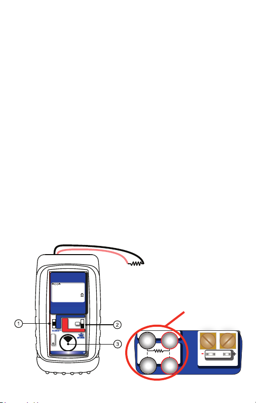
Read Resistance
Choose this function to measure resistance.
Move the power switch
w to READ then Double Click the
EZ-DIAL knob to get into the Menu. Turn the knob to scroll
through the settings and press the knob to make your selection.
Select OHMS for the FUNCTION, 400Ω or 4000Ω for the
RANGE.
Connect the Omega CL543B to the resistor or sensor using 2, 3
or 4 wires. The Omega CL543B automatically detects how many
wires are connected using a patented circuit and indicates each
wire that is connected. Any wires that are not connected or
broken are indicated by the CL543B. This is useful for
troubleshooting the sensor.
Signals above the maximum scale are limited by protection
circuitry with “OVER RANGE” on the display.
The Omega CL543B measures the input signal and constantly
updates the display with the current reading. Move the
EZ-CHECK switch
q to MAX to see the highest reading and to
MIN to see the lowest reading. Press and hold the knob e to
clear the MAX and MIN readings.
+
-
2 1
Ω
250.025
Automated RTD &
Thermocouple Calibrator
Pt 10, 50, 100, 200, 500 & 1000Ω
Cu 10 & 50Ω · Ni 120Ω
J · T · E · K · R · S · B · N · G · C · D · L· U · P · mV
SOURCE
MAX
HI
READ
SET
OFF
MIN
LO
Double Click
OVERLOAD
READ
Menu
Push & Turn
for
Fast Dialing
Push & Hold
to
Store/Step
2, 3 & 4 Wire Resistance Connections
+
mV
-
2
3
RTD
1
4
Ω
T/C
+-
Page 19
Page 24
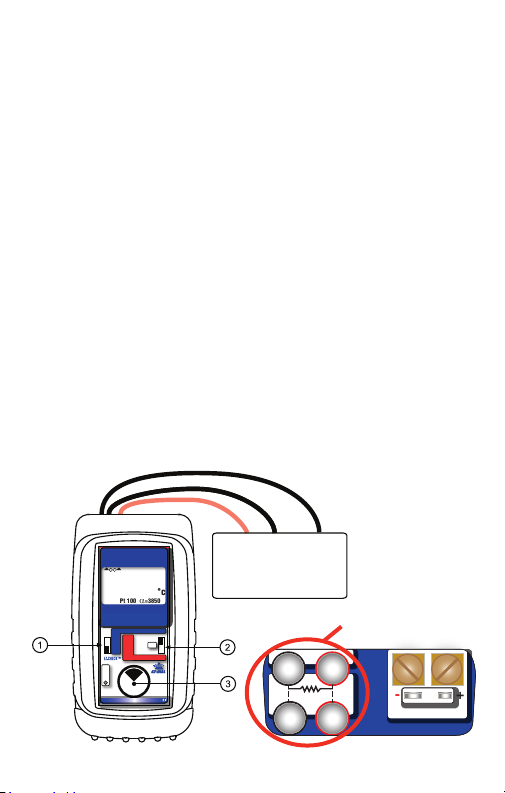
Source RTD
Choose this function to provide a simulated RTD signal into
controllers, temperature transmitters, indicators or any input
devices that measure RTD sensors.
Move the power switch
w to SOURCE then Double Click the
EZ-DIAL knob to get into the Menu. Turn the knob to scroll
through the settings and press the knob to make your selection.
Select RTD for the FUNCTION, °F or °C for the UNITS and RTD
(Platinum 10, 50, 100, 200, 500 & 1000 Ohm (alpha = 3850),
Platinum 100 Ohm (alpha = 3902, 3916, 3926), Copper 10 & 50
Ohm, and Nickel 120 Ohm).
Note: Platinum (Pt) 100Ω 3850 is the most common RTD type.
Disconnect all sensor wires from the devices to be calibrated and
connect the CL543B to the inputs of the device using 2, 3 or 4 wires.
Instantly output your SPAN and ZERO output settings by moving
the EZ-CHECK switch between HI and LO. You may also select
any third output setting (such as mid-range) using the SET
position on the EZ-CHECK switch. The output is adjusted in 0.1°
increments in LOW and 0.01° increments in HIGH resolution by
e.
turning the knob
Press and turn the knob for faster dialing
with 10° increments in both LOW and HIGH resolution.
Instrument with RTD Input
+
-
01.15mA PULSE
241
3
289.27 Ω
525.00
Pt 100 α=3850
LO
Automated RTD &
Thermocouple Calibrator
Pt 10, 50, 100, 200, 500 & 1000Ω
Cu 10 & 50Ω · Ni 120Ω
J · T · E · K · R · S · B · N · G · C · D · L· U · P · mV
SOURCE
MAX
HI
READ
SET
OFF
MIN
LO
Double Click
OVERLOAD
°c
READ
Menu
Push & Turn
for
Fast Dialing
Push & Hold
to
Store/Step
Controller
Temperature Transmitter
Temperature Indicator
Temperature Trip or Alarm
2, 3 & 4 Wire RTD Connections
mV
-
2
RTD
3
Ω
+
1
4
+-
T/C
Page 20
Page 25
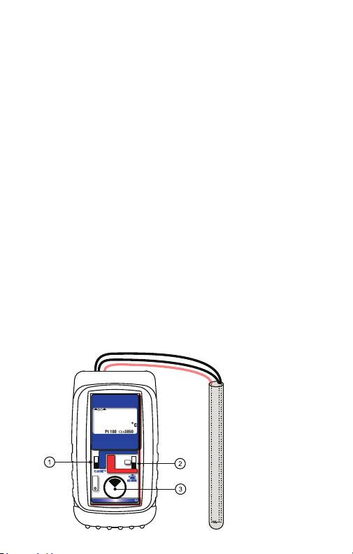
Read RTD Sensors
Choose this function to measure temperatures with an RTD
probe, sensor or any devices that output an RTD signal.
Move the power switch w to READ then Double Click the EZ-DIAL
knob to get into the Menu. Turn the knob to scroll through the
settings and press the knob to make your selection. Select RTD for
the FUNCTION, °F or °C for the UNITS and RTD (Platinum 10, 50,
100, 200, 500 & 1000 Ohm (alpha = 3850), Platinum 100 Ohm
(alpha = 3902, 3916, 3926), Copper 10 & 50 Ohm, and Nickel 120
Ohm).
Note: Platinum (Pt) 100Ω 3850 is the most common RTD type.
Connect the CL543B to the RTD sensor using 2, 3 or 4 wires. The
CL543B automatically detects how many wires are connected
using a patented circuit and indicates each wire that is connected.
Any wires that are not connected or broken are indicated by the
CL543B. This information is useful for troubleshooting the sensor.
Signals above the maximum scale are limited by protection
circuitry with “OVER RANGE” on the display.
The Omega CL543B measures the input signal and constantly
updates the display with the current reading. Move the EZ-CHECK
q to MAX to see the highest reading and to MIN to see the
switch
lowest reading. Press and hold the knob e to clear the MAX & MIN
readings.
+
-
2 1
3
138.51 Ω
100.00
°c
Pt 100 α=3850
MIN
Automated RTD &
Thermocouple Calibrator
Pt 10, 50, 100, 200, 500 & 1000Ω
Cu 10 & 50Ω · Ni 120Ω
J · T · E · K · R · S · B · N · G · C · D · L· U · P · mV
SOURCE
MAX
HI
READ
SET
OFF
MIN
LO
READ
Double Click
Menu
OVERLOAD
Push & Turn
for
Fast Dialing
Push & Hold
to
Store/Step
Page 21
Page 26

Troubleshooting RTD Instruments
When you are having an issue where an instrument won't read
an RTD sensor or you don't know if the calibrator is connected
properly the Omega CL543B has a function to measure and
display the fixed or pulsed sensor (excitation) current that the
instrument uses to measure the resistance of the RTD sensor.
Double click the
then turn the e DIAL KNOB to move to the second menu page
so the word DISPLAY appears at the top of the menu.
Turn the
cursor is pointing at SENSOR mA. Press the e DIAL KNOB to
toggle SENSOR mA ON.
Disconnect all sensor wires from the devices to be calibrated and
connect the Omega CL543B to the inputs of the device using 2, 3 or
4 wires. The sensor current generated by the instrument will be
indicated on the display followed by the word FIXED or PULSE. Older
single channel RTD instruments used a constant (fixed) current
source to measure an RTD sensor. Smart transmitters, multichannel
recorders and PLC or DCS input cards switch the current source
sequentially through the channels which is seen as an intermittent
(pulsed) current.
e DIAL KNOB at any time the unit is on and
e DIAL KNOB to move through the menu until the
Page 22
Page 27
Instrument with RTD Input
°C
00.21mA FIXED
289.27 Ω
525.00
01.15mA PULSE
289.27 Ω
525.00
°C
Controller
Temperature Transmitter
Temperature Indicator
T emperature Trip or Alarm
+
-
01.15mA PULSE
241
3
289.27 Ω
525.00
°c
Pt 100 α=3850
LO
Automated RTD &
Thermocouple Calibrator
Pt 10, 50, 100, 200, 500 & 1000Ω
Cu 10 & 50Ω · Ni 120Ω
J · T · E · K · R · S · B · N · G · C · D · L· U · P · mV
OVERLOAD
SOURCE
MAX
HI
READ
SET
OFF
MIN
LO
READ
Double Click
Menu
Push & Turn
for
Fast Dialing
Push & Hold
to
Store/Step
Page 23
Page 28

Troubleshooting RTD Sensors
When troubleshooting a problem with an RTD input it is useful to
check that the sensor and the wiring to the instrument is
operating properly.
The Omega CL543B automatically detects 2, 3 and 4 wire RTD
connections with a patented circuit. It will also display the
connections on the display and indicate when there is a missing
connection due to a loose connector, corrosion or a broken wire.
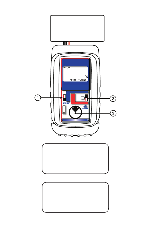
Here is an example of the CL543B reading a
sensor with all 4 wire connected.
Here is an example where connections are
made to a 4 wire sensor and the CL543B
indicates that only Wires 1, 2 & 4 are connected.
There may be a loose connection or a break in
wire 3 somewhere between the sensor and the
CL543B.
Page 24
Page 29

Page 25
Page 30

Omega CL543B Specifications
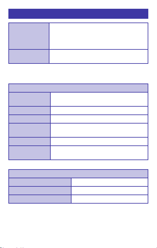
Unless otherwise indicated all specifications (except Cold
Junction) are rated from a nominal 23 °C, 70 % RH
General
Operating
Temperature Range
Storage
Temperature Range
Temperature
effect
Relative
Humidity Range
Normal Mode
Rejection
Common Mode
Rejection
Size
Weight 12.1 ounces, 0.34 kg with boot & batteries
Batteries Four “AA” Alkaline 1.5V (LR6)
Optional NiMh
Rechargeable
battery kit
Battery Life 50 Hours
Low Battery Low battery indication with nominal 1 hour
for 1 year from calibration
-20 to 60 °C (-5 to 140 °F)
-30 to 60 °C (-22 to 140 °F)
≤ ±50 ppm/°C;
Cold Junction Sensor ≤ ±25 ppm/°C
10 % ≤RH ≤90 % (0 to 35 °C), Non-condensing
10 % ≤RH≤ 70 % (35 to 60 °C), Non-condensing
50/60 Hz, 50 dB
50/60 Hz, 120 dB
5.63 x 3.00 x 1.60 in, 143 x 76 x 41mm
120 VAC for North America Only; charger,
four
NiMh batteries, AC & DC cords
[Part # 020-0103]
of operation left
(L x W x H)
Page 26
Page 31
Omega CL543B Specifications
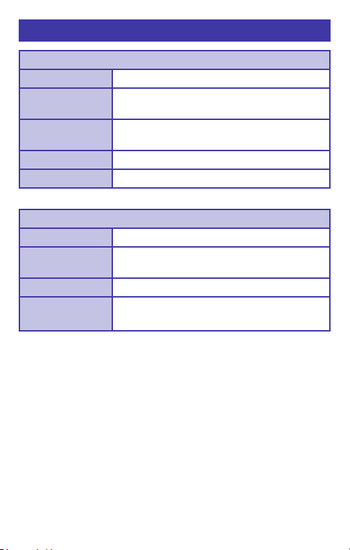
Protection
against
misconnection
Display High contrast graphic liquid crystal display.
Voltage Source
Ranges and
Resolution
Accuracy ±(0.008% of Setting + 0.006 mV)
Source Current
Output
Impedance
RMS Noise ≤ ± 0.0005 mV from 0.1 to 10 Hz
Short Circuit
Duration
Voltage Read
Range and Resolution Same as Voltage Source
Accuracy ±(0.008% of Reading + 0.006 mV)
Input resistance ≥ 10 MΩ
Over-voltage protection to 60 vrms (rated for
30 seconds)
Red LED indicates OVERLOAD or out of
range conditions
LED backlighting for use in low lit areas.
-13.000 to 80.000 mV & -13.0000 to 80.0000 mV
≥ 10 mA
< 0.3 Ohm
Infinite
Page 27
Page 32
Omega CL543B Specifications
Thermocouple Source
Accuracy ±(0.008% of Setting + 0.006 mV)
Cold Junction
Compensation
Output
Impedance
Source Current > 10 mA (drives 80 mV into 10 Ohms)
RMS Noise ≤ ± 0.0005 mV from 0.1 to 10 Hz
Thermocouple Read
Accuracy ±(0.008% of Reading + 0.006 mV)
Cold Junction
Compensation
Input Impedance
Open
Thermocouple
± 0.09°F (±0.05 °C) - Thermistor traceable to
NIST for 11 years
< 0.3 Ohms
± 0.09°F (±0.05 °C) - Thermistor traceable to
NIST for 11 years
> 10 Megohms
Threshold: 10,000 Ohms nominal
Pulse: < 10 microamp pulse for 300 milliseconds
Page 28
Page 33

Omega CL543B Specifications
RTD and Ohms Source
3 Wire & 4 Wire
Accuracy
From 1 to 10.2 mA
External Excitation
Current
Below 1 mA of
External Excitation
Current
2 Wire Accuracy
Resistance Ranges
RMS Noise
Allowable
Excitation
Current Range
Pulsed Excitation
Current
Compatibility
RTD and Ohms Read
Resistance Ranges Same as RTD and Ohms Source
Accuracy ±(0.015% of Reading + 0.05 Ohms)
Excitation
Current
±(0.015% of Setting + 0.05 Ohms)
Add ( ) to Accuracy
Add 0.1 Ohms to 3 Wire & 4 Wire Accuracy
400 Ohm Range: 0.00 to 401.00 & 0.000 to 401.000
4000 Ohm Range: 0.0 to 4010.0 & 0.00 to 4010.00
400 Ohm Range: ≤ ± 0.005 Ohms from 0.1
to 10 Hz
4000 Ohm Range: ≤ ± 0.05 Ohms from 0.1
to 10 Hz
400 Ohm Range:10.2 mA max; steady or pulsed/
intermittent
4000 Ohms Range: 1 mA max; steady or pulsed/
intermittent
DC to 0.01 second pulse width
0.9 mA to 401 Ohms, 0.4 mA to 4010 Ohms
(nominal)
0.025 mV
mA Excitation Current
Page 29
Page 34
Thermocouple Ranges & Accuracies
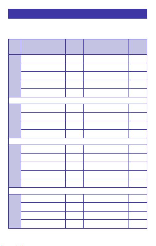
Table based on Accuracy:
≤ ± (0.008 % of Reading + 0.006 mV)
Note: Doesn’t include cold junction error of ±0.05°C
T/C Degrees C
Range
J -200.00 to -150.00 ±0.25° -328.00 to -238.00 ±0.55°
-150.00 to -50.00 ±0.17° -238.00 to -58.00 ±0.35°
-50.00 to 300.00 ±0.13° -58.00 to 572.00 ±0.24°
300.00 to 850.00 ±0.15° 572.00 to 1562.00 ±0.28°
850.00 to 1200.00 ±0.20° 1562.00 to 2192.00 ±0.36°
K -230.00 to -100.00 ±0.70° -382.00 to -148.00 ±1.26°
-100.00 to 600.00 ±0.19° -148.00 to 1112.00 ±0.34°
600.00 to 1000.00 ±0.24° 1112.00 to 1832.00 ±0.43°
1000.00 to 1371.1 ±0.31° 1832.00 to 2500.00 ±0.55°
T -260.00 to -240.00 ±1.66° -436.00 to -400.00 ±2.98°
-240.00 to -210.00 ±0.60° -400.00 to -346.00 ±1.07°
-210.00 to -100.00 ±0.41° -346.00 to -148.00 ±0.74°
-100.00 to 50.00 ±0.18° -148.00 to 122.00 ±0.33°
50.00 to 400.00 ±0.14° 122.00 to 752.00 ±0.24°
°C Degrees F
Range
°F
E -240.00 to -225.00 ±0.51° -400.00 to -373.00 ±0.92°
-225.00 to -100.00 ±0.27° -373.00 to -148.00 ±0.48°
-100.00 to 750.00 ±0.13° -148.00 to 1382.00 ±0.24°
750.00 to 1000.00 ±0.16° 1382.00 to 1832.00 ±0.29°
Page 30
Page 35
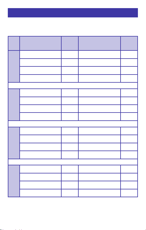
Thermocouple Ranges & Accuracies
Table based on Accuracy:
≤ ± (0.008 % of Reading + 0.006 mV)
Note: Doesn’t include cold junction error of ±0.05°C
T/C Degrees C
Range
R -18.30 to 250.00 ±1.26° -1.00 to 482.00 ±2.27°
250.00 to 750.00 ±0.64° 482.00 to 1382.00 ±1.14°
750.00 to 1600.00 ±0.54° 1382.00 to 2192.00 ±0.97°
1600.00 to 1767.80 ±0.63° 2192.00 to 3214.00 ±1.13°
S -18.30 to 150.00 ±1.22° -1.00 to 302.00 ±2.20°
150.00 to 500.00 ±0.72° 302.00 to 932.00 ±1.30°
500.00 to 1650.00 ±0.63° 932.00 to 3002.00 ±1.14°
1650.00 to 1767.80 ±0.73° 3002.00 to 3214.00 ±1.31°
B 315.60 to 550.00 ±1.88° 600.00 to 1022.00 ±3.39°
550.00 to 900.00 ±1.03° 1022.00 to 1652.00 ±1.86°
900.00 to 1150.00 ±0.72° 1652.00 to 2102.00 ±1.30°
1150.00 to 1820.00 ±0.63° 2102.00 to 3308.00 ±1.14°
-230.00 to -100.00 ±1.10° -382.00 to -148.00 ±1.98°
N
-100.00 to 0.00 ±0.30° -148.00 to 32.00 ±0.53°
0.00 to 1100.00 ±0.24° 32.00 to 2012.00 ±0.44°
1100.00 to 1300.00 ±0.27° 2012.00 to 2372.00 ±0.49°
°C Degrees F
Range
°F
Page 31
Page 36
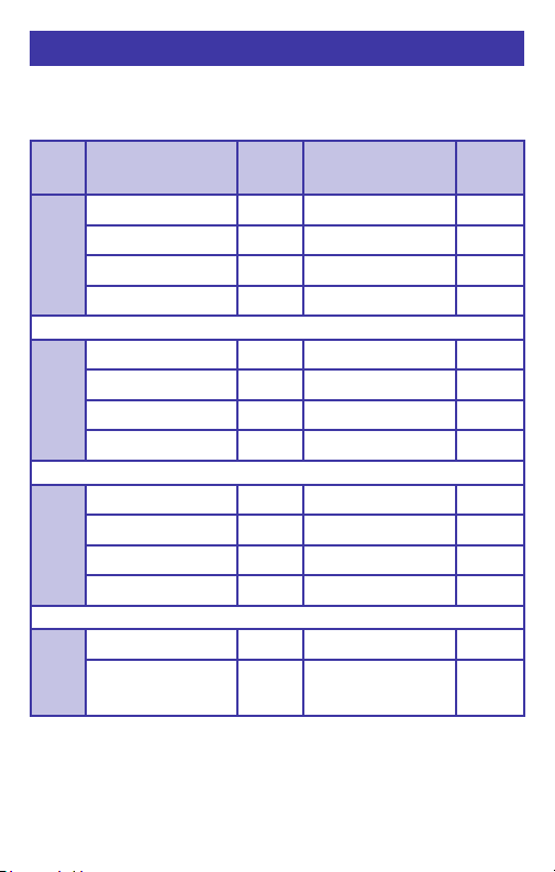
Thermocouple Ranges & Accuracies
Table based on Accuracy:
≤ ± (0.008 % of Reading + 0.006 mV)
Note: Doesn’t include cold junction error of ±0.05°C
T/C Degrees C
Range
100.00 to 450.00 ±1.14° 212.00 to 842.00 ±2.05°
G
(W)
440.00 to 1700.00 ±0.44° 842.00 to 3092.00 ±0.79°
1700.00 to 2000.00 ±0.54° 3092.00 to 3632.00 ±0.97°
2000.00 to 2320.00 ±0.73° 3632.00 to 4208.00 ±1.32°
C
-
1.10 to 1150.00±0.44° 30.00 to 2102.00 ±0.80°
(W5)
1150.00 to 1750.00 ±0.61° 2102.00 to 3182.00 ±1.09°
1750.00 to 2050.00 ±0.74° 3182.00 to 3722.00 ±1.33°
2050.00 to 2320.00 ±0.99° 3722.00 to 4208.00
D
-1.00 to 150.00 ±0.63° 30.00 to 302.00 ±1.13°
(W3)
150.00 to 1200.00 ±0.41° 302.00 to 2192.00 ±0.73°
1200.00 to 1700.00 ±0.51° 2192.00 to 3092.00 ±0.92°
1700.00 to 2320.00 ±0.97° 3092.00 to 4208.00 ±1.75°
P
0.00 to 950.00 ±0.23° 32.00 to 1742.00 ±0.41°
950.00 to 1395.00 ±0.34° 1742.00 to 2543.00 ±0.61°
°C Degrees F
Range
±
1.79°
°F
Page 32
Page 37
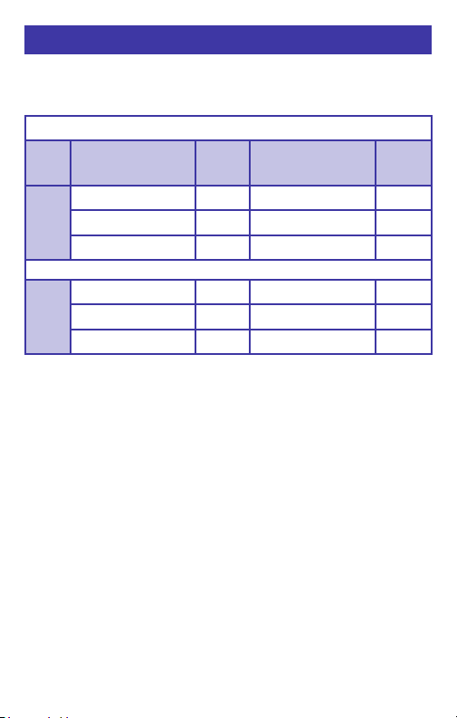
Thermocouple Ranges & Accuracies
Table based on Accuracy:
≤ ± (0.008 % of Reading + 0.006 mV)
Note: Doesn’t include cold junction error of ±0.05°C
DIN Wire
T/C Degrees C
Range
-200.00 to -100.00 ±0.21°-328.00 to -148.00 ±0.38°
L
J-DIN
-100.00 to 350.00 ±0.13° -148.00 to 662.00 ±0.24°
350.00 to 900.00 ±0.15° 662.00 to 1652.00 ±0.27°
-200.00 to -150.00 ±0.37° -328.00 to -238.00 ±0.66°
U
T-DIN
-150.00 to 100.00 ±0.22° -238.00 to 212.00 ±0.40°
100.00 to 600.00 ±0.15° 212.00 to 1112.00 ±0.28°
°C Degrees F
Range
°F
Page 33
Page 38

RTD Ranges & Accuracies
Table based on 3 & 4 Wire RTD (ITS-90) Accuracy*:
RTD
Type
Pt 100 Ohm
DIN/IEC/JIS
a
=1.3850
Pt 10 Ohm
DIN/IEC/1989
a
=1.3850
Pt 50 Ohm
DIN/IEC/1989
a
=1.3850
Pt 200 Ohm
DIN/IEC/1989
a
=1.3850
Pt 500 Ohm
DIN/IEC/1989
a
=1.3850
Pt 1000
DIN/IEC/1989
a
=1.3850
*Read based on 1.0 mA of
fixed excitation current
≤ ± (0.015 % of Reading +0.05 Ohms)
Degrees C
1989
Ohm
Range
-200.00 to -150.00
-150.00 to 360.00
360.00 to 740.00
740.00 to 850.00
-200.00 to -120.00
-120.0 to 210.00
210.00 to 370.00
370.00 to 650.00
650.00 to 850.00
-200.00 to 200.00
200.00 to 550.00
550.00 to 850.00
-200.00 to -120.00
-120.00 to 180.00
180.00 to 450.00
450.00 to 680.00
680.00 to 850.00
-200.00 to -90.00
-120.00 to 180.00
180.00 to 450.00
450.00 to 680.00
680.00 to 850.00
-200.00 to 170.00
170.00 to 470.00
470.00 to 730.00
730.00 to 850.00
°C
±0.13°
±0.24°
±0.34°
±0.37°
±1.24°
±1.44°
±1.54°
±1.74°
±1.91°
±0.34°
±0.44°
±0.54°
±0.08°
±0.14°
±0.19°
±0.24°
±0.29°
±0.08°
±0.14°
±0.19°
±0.24°
±0.29°
±0.08°
±0.14°
±0.19°
±0.22°
Page 34
Degrees F
Range
-328.0 to -238.00
-238.00 to 660.00
660.00 to 1364.00
1364.00 to 1562.00
-328.00 to -184.00
-184.00 to 410.00
410.00 to 698.00
698.00 to 1202.00
1202.00 to 1562.00
-328.00 to 392.00
392.00 to 1022.00
1022.00 to 1562.00
-328.00 to -184.00
-184.00 to 356.00
356.00 to 842.00
842.00 to 1256.00
1256.00 to 1562.00
-328.00 to -194.00
-184.00 to 356.00
356.00 to 842.00
842.00 to 1256.00
1256.00 to 1562.00
-328.00 to 338.00
338.00 to 878.00
878.00 to 1346.00
1346.00 to 1562.00
°F
±0.24°
±0.44°
±0.61°
±0.67°
±2.24°
±2.59°
±2.77°
±3.14°
±3.44°
±0.62°
±0.80°
±0.98°
±0.14°
±0.24°
±0.34°
±0.44°
±0.52°
±0.14°
±0.24°
±0.34°
±0.44°
±0.52°
±0.14°
±0.24°
±0.34°
±0.39°
Page 39

RTD Ranges & Accuracies
Table based on 3 & 4 Wire RTD (ITS-90) Accuracy*:
RTD
Type
Pt 100
Ohm
(Burns)
a
=1.3902
Pt 100
Ohm
(Old JIS
1981)
a
=1.3916
Pt 100
Ohm
(US Lab)
a
=1.3926
≤ ± (0.015 % of Reading +0.05 Ohms)
Degrees C
Range
-195.61 to -100.00
-100.00 to 370.00
370.00 to 648.90
-200.00 to -140.00
-140.00 to 130.00
130.00 to 370.00
370.00 to 648.90
-200.00 to -140.00
-140.00 to 130.00
130.00 to 380.00
380.00 to 610.00
610.00 to 850.00
°C
±0.14°
±0.24°
±0.31°
±0.13°
±0.19°
±0.24°
±0.31°
±0.13°
±0.19°
±0.24°
±0.30°
±0.37°
Degrees F
Range
-320.10 to -148.00
-148.00 to 698.00
698.00 to 1200.00
-328.00 to -220.00
-220.00 to 266.00
266.00 to 698.00
698.00 to 1200.00
-328.00 to -220.00
-220.00 to 266.00
266.00 to 716.00
716.00 to 1130.00
1130.00 to 1562.00
°F
±0.26°
±0.44°
±0.56°
±0.24°
±0.34°
±0.44°
±0.56°
±0.24°
±0.34°
±0.44°
±0.54°
±0.66°
Copper 10
Ohm
(Minco)
a
=1.4274
Copper 50
Ohm
a
=1.4280
Ni 120
Ohm
a=1.6720
*Read based on 1.0 mA of
fixed excitation current
-200.00 to -150.00
-150.00 to 90.00
90.00 to 260.00
-50.00 to 150.00 ±0.29° -58.00 to 302.00 ±0.52°
-80.00 to 260.00 ±0.10° -112.00 to 500.00 ±0.17°
(Pure)
±1.24°
±1.34°
±1.36°
Page 35
-328.00 to -238.00
-238.00 to 194.00
194.00 to 500.00
±2.24°
±2.42°
±2.44°
Page 40

Guaranteed compatible with smart
transmitters, multichannel recorders as
well as PLC and DCS input cards.
Additional Information
Omega Calibrators are manufactured in the USA.
product is calibrated on equipment traceable to NIST and
includes a Certificate of Calibration. Test Data is available for an
additional charge.
Omega recommends a calibration interval of one year.
Contact us for recalibration and repair services.
Page 36
This
Page 41

OMEGA ENGINEERING, INC. warrants this unit to be free of defects in materials and
workmanship for a period of 37 months from date of purchase. OMEGA’s Warranty
adds an additional one (1) month grace period to the normal three (3) year product
warranty to cover handling and shipping time. This ensures that OMEGA’s customers
receive maximum coverage on each product.
If the unit malfunctions, it must be returned to the factory for evaluation. OMEGA’s
Customer Service Department will issue an Authorized Return (AR) number immediately
upon phone or written request. Upon examination by OMEGA, if the unit is found to be
defective, it will be repaired or replaced at no charge. OMEGA’s WARRANTY does not
apply to defects resulting from any action of the purchaser, including but not limited to
mishandling, improper interfacing, operation outside of design limits, improper repair,
or unauthorized modification. This WARRANTY is VOID if the unit shows evidence of
having been tampered with or shows evidence of having been damaged as a result
of excessive corrosion; or current, heat, moisture or vibration; improper specification;
misapplication; misuse or other operating conditions outside of OMEGA’s control.
Components in which wear is not warranted, include but are not limited to contact
points, fuses, and triacs.
OMEGA is pleased to offer suggestions on the use of its various products.
However, OMEGA neither assumes responsibility for any omissions or errors
nor assumes liability for any damages that result from the use of its products
in accordance with information provided by OMEGA, either verbal or written.
OMEGA warrants only that the parts manufactured by the company will be
as specified and free of defects. OMEGA MAKES NO OTHER WARRANTIES OR
REPRESENTATIONS OF ANY KIND WHATSOEVER, EXPRESSED OR IMPLIED,
EXCEPT THAT OF TITLE, AND ALL IMPLIED WARRANTIES INCLUDING ANY
WARRANTY OF MERCHANTABILITY AND FITNESS FOR A PARTICULAR
PURPOSE ARE HEREBY DISCLAIMED. LIMITATION OF LIABILITY: The remedies
of purchaser set forth herein are exclusive, and the total liability of OMEGA
with respect to this order, whether based on contract, warranty, negligence,
indemnification, strict liability or otherwise, shall not exceed the purchase
price of the component upon which liability is based. In no event shall OMEGA
be liable for consequential, incidental or special damages.
CONDITIONS: Equipment sold by OMEGA is not intended to be used, nor shall it be
used: (1) as a “Basic Component” under 10 CFR 21 (NRC), used in or with any nuclear
installation or activity; or (2) in medical applications or used on humans. Should any
Product(s) be used in or with any nuclear installation or activity, medical application,
used on humans, or misused in any way, OMEGA assumes no responsibility as set
forth in our basic WARRANTY/ DISCLAIMER language, and, additionally, purchaser will
indemnify OMEGA and hold OMEGA harmless from any liability or damage whatsoever
arising out of the use of the Product(s) in such a manner.
Direct all warranty and repair requests/inquiries to the OMEGA Customer Service
Department. BEFORE RETURNING ANY PRODUCT(S) TO OMEGA, PURCHASER MUST
OBTAIN AN AUTHORIZED RETURN (AR) NUMBER FROM OMEGA’S CUSTOMER
SERVICE DEPARTMENT (IN ORDER TO AVOID PROCESSING DELAYS). The assigned
AR number should then be marked on the outside of the return package and on any
correspondence. The purchaser is responsible for shipping charges, freight, insurance
and proper packaging to prevent breakage in transit.
FOR WARRANTY RETURNS, please
have the following information available
BEFORE contacting OMEGA:
1. Purchase Order number under which
the product was PURCHASED,
2. Model and serial number of the
product under warranty, a nd
3. Repair instructions and/or specific
problems relative to the product.
OMEGA’s policy is to make running changes, not model changes, whenever an improvement is
possible. This affords our customers the latest in technology and engineering.
OMEGA is a registered trademark of OMEGA ENGINEERING, INC.
© Copyright 2016 OMEGA ENGINEERING, INC. All rights reserved. This document may not be copied,
photocopied, reproduced, tran slated, or reduced to any electronic medium or machine-readable form,
in whole or in part, without the prior written consent of OMEGA ENGINEERING, INC.
WARRANTY/ DISCLAIMER
RETURN REQUESTS/ INQUIRIES
FOR NON-WARRANTY REPAIRS,
OMEGA for current repair charges. Have
the following information available BEFORE
contacting OMEGA:
1. Purchase Order number to cover the COST
of the repair,
2. Model and serial number of the product, and
3. Repair instructions and/or specific problems
relative to the product.
consult
Page 42

Where Do I Find Everything I Need for
Process Measurement and Control?
OMEGA…Of Course!
Shop online at omega.com
TEMPERATURE
MU
Thermocouple, RTD & Thermistor Probes, Connectors, Panels &
Assemblies
MU
Wire: Thermocouple, RTD & Thermistor
MU
Calibrators & Ice Point References
MU
Recorders, Controllers & Process Monitors
MU
Infrared Pyrometers
PRESSURE, STRAIN AND FORCE
MU
Transducers & Strain Gages
MU
Load Cells & Pressure Gages
MU
Displacement Transducers
MU
Instrumentation & Accessories
FLOW/LEVEL
MU
Rotameters, Gas Mass Flowmeters & Flow Computers
MU
Air Velocity Indicators
MU
Turbine/Paddlewheel Systems
MU
Totalizers & Batch Controllers
pH/CONDUCTIVITY
MU
pH Electrodes, Testers & Accessories
MU
Benchtop/Laboratory Meters
MU
Controllers, Calibrators, Simulators & Pumps
MU
Industrial pH & Conductivity Equipment
DATA ACQUISITION
MU
Data Acquisition & Engineering Software
MU
Communications-Based Acquisition Systems
MU
Plug-in Cards for Apple, IBM & Compatibles
MU
Data Logging Systems
MU
Recorders, Printers & Plotters
HEATERS
MU
Heating Cable
MU
Cartridge & Strip Heaters
MU
Immersion & Band Heaters
MU
Flexible Heaters
MU
Laboratory Heaters
ENVIRONMENTAL MONITORING AND CONTROL
MU
Metering & Control Instrumentation
MU
Refractometers
MU
Pumps & Tubing
MU
Air, Soil & Water Monitors
MU
Industrial Water & Wastewater Treatment
MU
pH, Conductivity & Dissolved Oxygen Instruments
sm
M5553/0216
 Loading...