

Page 1
CL543
Dual T/C & RTD Calibrator With Auto Stapping
INSTRUCTION
SHEET
M4241-0406
Shop online at: omega.com e-mail: [email protected]
For latest product manuals: omegamanual.info
1-12
Basic Keypad Operations
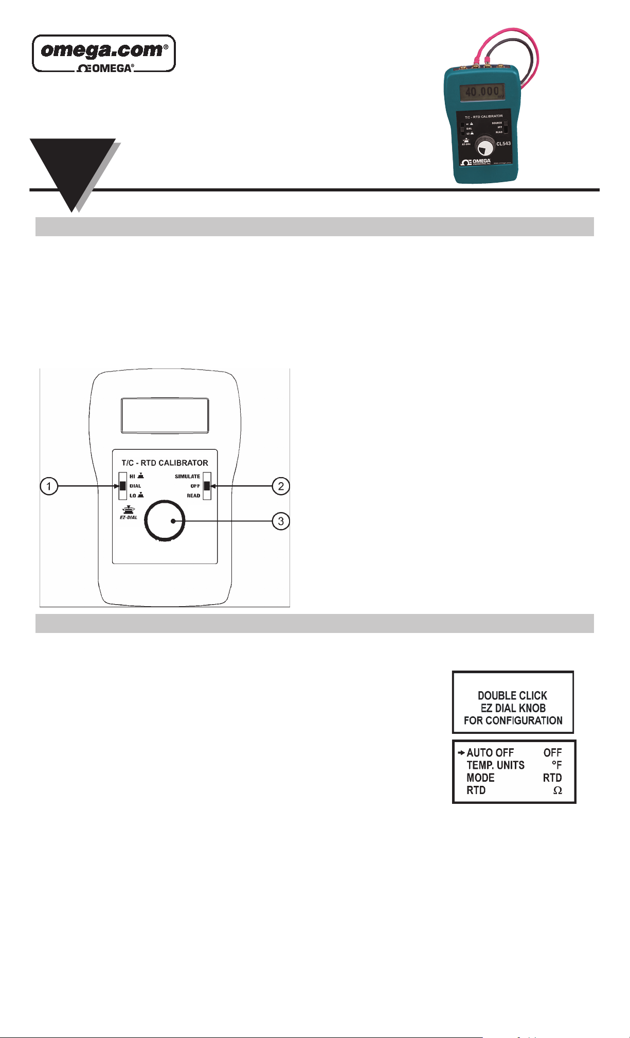
1
EZ-Check™ Switch
For Simulation - Slide the switch to select from three user stored
values for the desired calibration points. The user can select HI, DIAL,
and LO positions. These values can easily be changed to suit the
calibration requirements. Also these stored values can be use for Auto
Stepping.
For Read - Slide the switch to the DIAL position. The CL543 will
begin making readings. Slide the switch to high and you will get the
highest point read and then slide the switch to the low position and
you will get the lowest range.
2
SIMULATE/OFF/READ Switch
Turn the CL543 on to SIMULATE to output a
temperature, ohms, or mV. Turn the unit to READ
to read temperature, ohms, or mV.
3
EZ-Dial™ Knob
Turn the knob to change temperature in 0.1º or
0.01º increments. Push and turn for faster dialing.
Double push to get into the CL543 Configuration
mode to auto Battery on/off, select Back lighting,
C° or F°, RTD or T/C types, Store or step feature,
select step size and step time. Then press to
store desired EZ-Check™ HI/LO points in
SIMULATE mode. Push to clear EZ-Check™
HI/LO
points in READ mode.
Note: The CL543 is a Universal Temperature
Calibrator that works great calibrating Multichannel Chart Recorders, Data Acquisition &
Computer Systems and Smart transmitters.
The CL543 is GUARANTEED to work with ALL
transmitters, recorders and any other RTD input
devices that use intermittent, or pulsed excitation
current to measure the resistance of the RTD. The
CL543 automatically adjusts to the correct
excitation current.
CL543 Configuration
Instructions for Enabling and Disabling the Configuration Options
1. Turn the CL543 on to SIMULATE or read.
2. Double Click the EZ-Dial™ Knob at any time to enter configuration menu.
3. Select options by turning the EZ-Dial™ Knob clockwise until the arrow points to the
desired option.
4. The option can be enabled or disabled by tapping the EZ-Dial™ Knob.
The CL543 configuration menu will exit automatically after 5 seconds of inactivity and go
to normal operation with the options selected. These options are recalled at turn on until they
are changed again.
NOTE: Changing the battery will reset menu options to factory settings.
Model CL543 Configuration Menu
Auto Off ON/OFF
If Auto Off is ON, the unit will turn off after 30 minutes to save battery life, if there is no user activity. If Auto Off is OFF the unit will
stay on until it is turned off from the keypad. This is typically useful for manual loading or continuous use. Press the EZ-Dial™ Knob
to select.
Display Units °C/°F
Pressing the EZ-Dial™ Knob to toggles between °C or °F.
Mode - RTD or T/C
You are able to select the different, RTD types - Pt100 α=3850, Pt100 α=3902, Pt100 α=3916, Pt100 α=3926,
Cu10 α=427, Cu50 α=428, Ni110 Bristol, Ni120 α=672, Ω
T/C types - B, E, J, K, N, R, S, T, or mV
To change RTD or T/C type, press the EZ-Dial™ Knob. Turn the EZ-Dial™ Knob to scroll through the list of available types. Press
again to save and return to the configuration menu.
CL543
CL543
Page 2
CL543 Operating Instructions
2-12
Store/Step
To select three test point values you first have to select Store,
1. Select your high range by sliding the Hi/Lo slide switch to the HI position and dial it to the range desired then press and
hold the EZ-Dial™ Knob until STORED appears to store the value.
2. Slide the Hi/Lo slide switch to the middle position (dial) and dial it to the range desired. You do not have to press store
to keep this value. This position if so desired is adjustable.
3. Slide the Hi/Lo slide switch to the Lo position and dial it to the range desire then press and hold the EZ-Dial™ Knob
until STORED appears to store the value.
Memory will be maintained even when power is off.
To start stepping after you have selected the step size and step time as described below scroll
back up the configuration mode to STORE/STEP and select step then let the unit time out of
configuration mode. Place the slide switch in either Hi or Lo position and press and hold the
EZ-Dial™ Knob to start and also to stop.
Step Size
To change the step size, press the EZ-Dial™ Knob to find the desired step size or %.
Step Time
To change the step time, press the EZ-Dial™ Knob to find the desired step time indicated in seconds. This is the time in-between
each step.
Display Resolution
To Select between High resolution 0.01º, 000.000Ω or Low resolution 0.1º, 000.00Ω, press the EZ-Dial™ Knob to find the desired
display setting.
Double-click the EZ-Dial™ Knob to return to the configuration menu at any time of operation.
Read Mode
Slide the SIMULATE/OFF/READ switch to READ for direct RTD or T/C input. Then slide the EZ-Check™ Switch to DIAL position to
monitor the RTD or T/C input. The CL543 displays temperature corresponding to resistance input for the selected RTD type.
Memory is updated every second once the unit is turned on or the CLEAR option is used. This helps when looking at temperature drift
or for any other deviation. Slide the EZ-Check™ Switch to HI and LO to recall maximum and minimum saved readings. Observe the
“HI” and “LO” switch position indicators in the display. Press and hold the EZ-Dial™ Knob to clear saved readings. The display flashes
“CLEARED” as a confirmation.
Be sure the switch is in the DIAL position to monitor input.
Turning the EZ-Dial™ Knob has no effect in read mode.
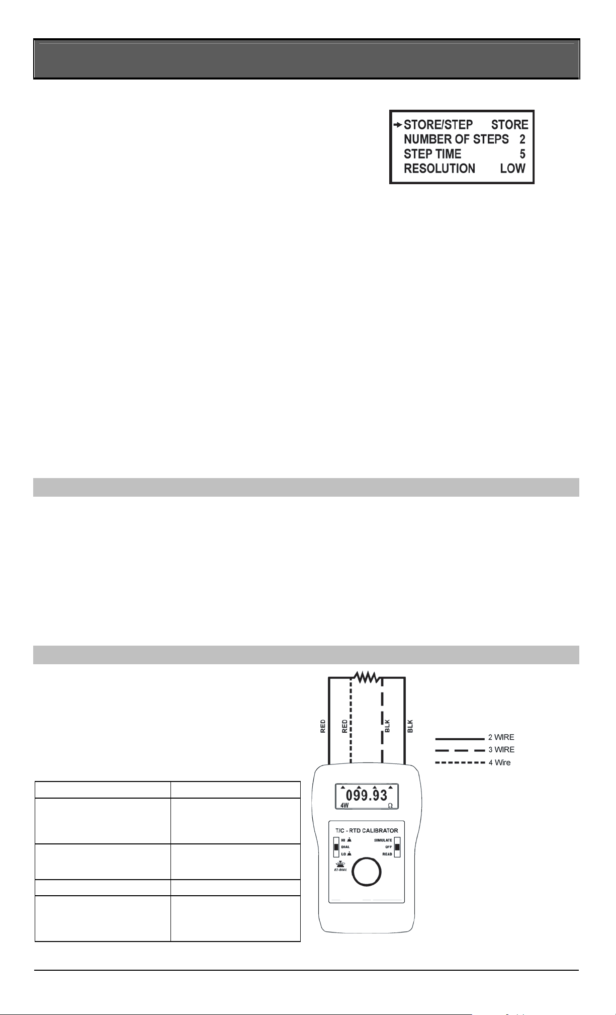
RTD READ ONLY-Automatic 2, 3, or 4 wire detect: Connect 2, 3, or 4 wires to the RTD sensor. Follow the connection diagrams.
The CL543 indicates “2W”, “3W”, or “4W” in the lower left corner of the display. It will also place an arrow under each connected
wire to show which wire is connected and will indicate if there is an “ERROR”. Use this feature for troubleshooting unconnected leads
or sensors. See below figure.
RTD Read Connection, (wire kit supplied)
RTD Read Mode Connection
Display Indications:
Check Connections 1 and 2 You have to have wires 1
and 2 connected correctly
before trying to connect up
to a 3 or 4 wire transmitter
OVERRANGE or
UNDERRANGE
The resistance input exceeds
the range of the selected
RTD type.
OPEN RTD No RTD is connected.
MISCONNECT The CL543 is incorrectly
connected for a 3-wire or 4wire reading. Both black
leads are required.
CL543
Page 3
CL543 Operating Instructions
3-12
Source Mode
Slide the SIMULATE/OFF/READ switch to SIMULATE for direct RTD or T/C output. The CL543 outputs resistance corresponding to
temperature for the selected RTD or outputs mV corresponding to temperature for the selected T/C type.
Turn the EZ-Dial™ Knob to change temperature, push and turn for faster dialing.
Slide the EZ-Check™ Switch to HI or LO to recall stored settings. While in the HI or LO position, dial a new setting and press the
EZ-Dial™ Knob to store. The DIAL position always holds the last setting dialed there. Using the STORED Values gives you very
accurate values for repeatability. Adjusting the EZ-Dial™ Knob you can check for controller actions, trip points or hysteresis.
Double-click the EZ-Dial™ Knob to return to the configuration menu.
Auto Stepping in Source Mode
Select the step size by pressing the EZ-Dial™ Knob to find the desired step size or %. Select the step time by pressing the EZ-Dial™
Knob to find the desired step time indicated in seconds.
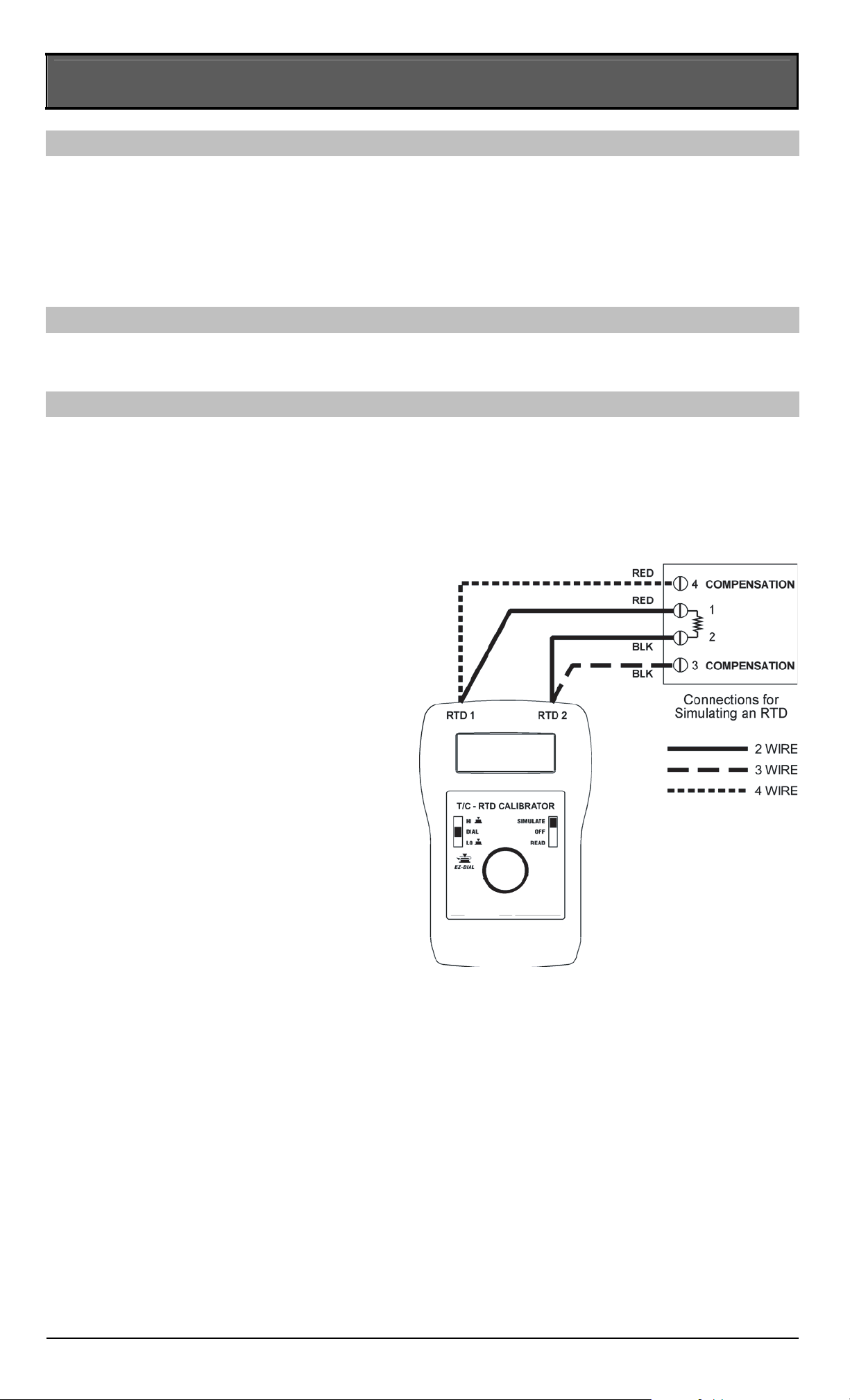
RTD Connection Diagrams, (wire lead kit supplied)
SOURCE ONLY: (See opposite figure)
To connect to a 2 wire transmitter connect one red lead to
post 1 (RTD1) and connect one black lead to post 2 (RTD2).
To connect to a 3 wire transmitter connect one red lead to
post 1 (RTD1) and connect two black leads to post 2 (RTD2).
To connect to a 4 wire transmitter connect two red leads to
post 1 (RTD1) and connect two black leads to post 2 (RTD2).
NOTE:
3 WIRE & 4 WIRE TERMINALS ARE FOR READ MODE
ONLY. See figure page 2.
CL543
Page 4
CL543 Operating Instructions
4-12
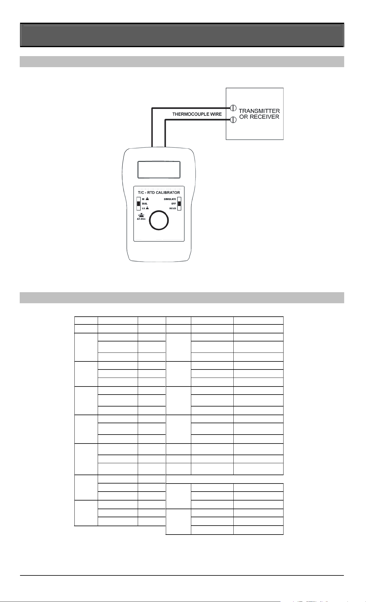
T/C Connection Diagram
Two Wire Connection to Transmitter
Color Codes FOR T/C Connections
T/C T/C ISA/ANSI T/C T/C ISA/ANSI
TYPE MATERIAL COLOR TYPE MATERIAL COLOR
+IRON WHITE +NICROSIL ORANGE
-
CONSTANTAN RED -NISIL RED
J
JACKET BLACK
N
JACKET ORANGE
+CHROMEGA
®
+CHROMEGA
®
YELLOW +TUNGSTEN WHITE
-ALOMEGA
®
RED G -W26/Re RED
K
JACKET YELLOW (W) JACKET WHITE/BLUE
+COPPER BLUE
+W5/Re WHITE
-
CONSTANTAN RED C -W26/Re RED
T
JACKET BLUE (W5) JACKET WHITE/RED
PURPLE +W3/Re WHITE
-
CONSTANTAN RED -W25/Re RED
E
JACKET PURPLE
D
JACKET WHT/YEL
+Pt/13rH BLACK
+Pd55/Pt31/Au1
4YELLOW
-PLATINUM RED P -Au65/Pd35 RED
R
JACKET GREEN
Platinel
® JACKET BLACK
+Pt/10Rh BLACK din colors
-PLATINUM RED +IRON RED
S
JACKET GREEN L - CONSTANTAN BLUE
+Pt30Rh GREY J DIN JACKET BLUE
-Pt/6Rh RED +COPPER RED
B
JACKET GREY U -CONSTANTAN BROWN
T DIN JACKET BROWN
CHROMEGA® and ALOMEGA® are registered trademarks of Omega Engineering, Inc.
PLATINEL
®
is a registered trademark of Engelhard Corporation.
CL543
Page 5

CL543 Operating Instructions
5-12
Specifications
General Specifications:
Unless otherwise indicated all specifications are rated from a nominal 23 °C, 70 % RH for 1 year from calibration.
Temperature Range -25 to 60 °C (-10 to 140 °F)
Relative Humidity Range 10 % ≤RH ≤90 % (0 to 35 °C), Non-condensing
10 % ≤RH ≤70 % (35 to 60 °C), Non-condensing
Overall Size 4.9 X 3.15 X 1.82 inches (125.5 X 80 X 46.2 mm)
Overall Weight (including 9V battery) 8.3 oz (235 grams)
Battery 9V Alkaline provides 45 hours of continuous use
Low battery indication with nominal 1 hour of operation left
Overload Protection Overload protected to 60 volts for up to 30 seconds in duration
Display High-contrast graphic liquid crystal display with 0.357” (9.07 mm) high digits
Maximum Resolution 0.01°, 0.001Ω or 0.001mV
Thermocouple Specifications:
Accuracy ±(0.004 % of mV reading + 0.003 mV) in mV (at 90 days)
±(0.008 % of mV reading + 0.006 mV) in mV (at 1 year)
Temperature Coefficient of mV Source 50 ppm/°C of output range
Cold Junction Calibration Accuracy ±0.1 °C (0.2 °F)
Cold Junction Sensor Temperature Coefficient ±0.025 °/° in ambient temperature (°C or °F)
Output Range -13.000 to +80.000 mV
Output Noise ±5 µV pp from 0.1 Hz to 10 Hz
Output Impedance 0.2 Ω (200 nV/µA)
Output Source Current < 8 mA
Input Noise < ±1 LSD from 0.1 Hz to 10 Hz
Input Impedance > 10 MΩ
Open T/C Test Pulse < 10µA for 300 ms
Open T/C Response Time < 3 seconds
Open T/C Threshold 10 kΩ nominal
RTD Specifications:
Accuracy ±(0.008 % of reading + 0.03Ω) in Ohms (at 90 days)
±(0.015 % of reading + 0.05 Ω) in Ohms (at 1 year)
Temperature Coefficient 10 ppm/°C
Allowable Excitation Current 100 µA to 10.2 mA, steady or pulsed/intermittent/smart
for excitation currents below 100µA add ±10µV/Excitation Current (units are in Ω)
Pulsed Excitation Current Compatibility DC to 0.01 second pulse widths
Read Mode Excitation Current 620µA nominal
Available Options:
Carrying Case Part Number: 020-0205 case with logo
T/C Wire Kit Part Number: 020-0202 (J, T, E, K thermocouple leads with mini plug)
Part Number: 020-0203 (B, R/S, N thermocouple leads with mini plug)
Page 6
CL543 Operating Instructions
6-12
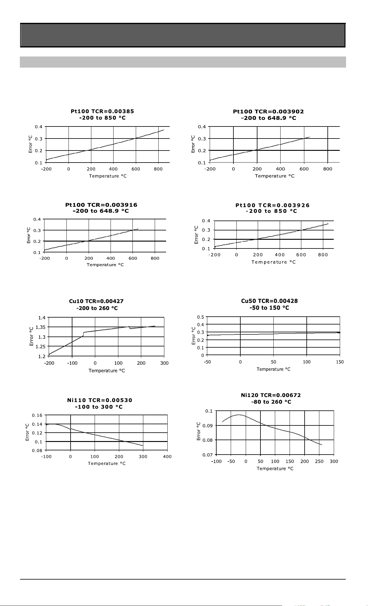
RTD Temperature Accuracy
The following charts give worst-case temperature accuracy based on stated resistance accuracy at 1 year.
Excitation current 100µ to 10.2 mA
Page 7
CL543 Operating Instructions
7-12
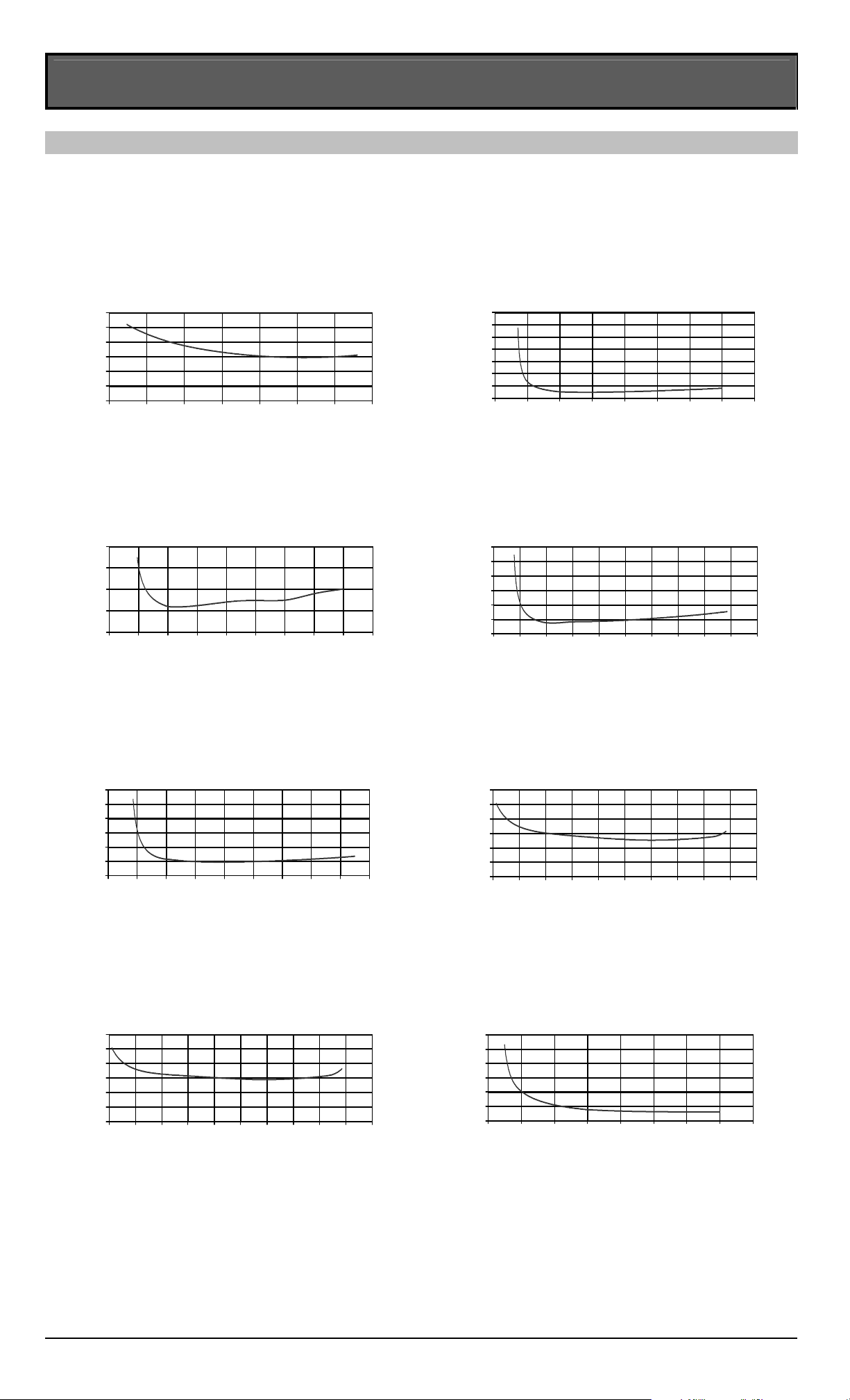
Thermocouple Temperature Accuracy
The following charts give worst-case temperature accuracy based on stated millivolt accuracy at 1 year. Temperature is
uncompensated on the horizontal axis, referenced to 0 °C. Cold Junction calibration accuracy of 0.1 °C is not included in the
temperature error.
TYPE B
594 to 1820 °C
0
0.2
0.4
0.6
0.8
1
1.2
005
007
0
0
9
0
0
1
1
0
0
3
1
0051
00
7
1
0
0
9
1
Temperature °C
C
°
r
orr
E
TYPE E
-260 to 1000 °C
0
0.2
0.4
0.6
0.8
1
1.2
1.4
004-
002-
0
002
004
006
008
0
00
1
0
02
1
Temperature °C
C° r
o
rrE
TYPE J
-210 to 1200 °C
0
0.1
0.2
0.3
0.4
004
-
0
02
-
0
0
0
2
00
4
00
6
00
8
0
0
0
1
0
02
1
0
04
1
Temperature °C
C
° r
orr
E
TYPE K
-245 to 1372 °C
0
0.2
0.4
0.6
0.8
1
1.2
0
04-
00
2-
0
002
004
00
6
00
8
000
1
0021
00
41
00
6
1
Temperature °C
C
°
r
o
rrE
TYPE N
-229 to 1300 °C
0
0.2
0.4
0.6
0.8
1
1.2
004-
00
2-
0
00
2
004
00
6
00
8000
1
00
2
1
0
0
41
Temperature °C
C
°
rorrE
TYPE R
24 to 1768 °C
0
0.2
0.4
0.6
0.8
1
1.2
0
00
2
0
0
4
0
0
6
008
0
0
0
1
0021
0
0
4
1
0061
0081
0
0
0
2
Temperature °C
C°
r
o
rrE
TYPE S
21 to 1768 °C
0
0.2
0.4
0.6
0.8
1
1.2
0
002
004
006
008
0001
0
02
1
0041
0061
0
0
81
0002
Temperature °C
C
°
r
orrE
TYPE T
-251 to 400 °C
0
0.2
0.4
0.6
0.8
1
1.2
003-
00
2-
0
0
1-
0
0
01
0
02
00
3
00
4
00
5
Temperature °C
C°
ro
rrE
Page 8

8-12
Equipment Needed:
1. Precision OHM Meter with accuracy of 0.0068% at 400 Ω.
2. Precision OHM Source with accuracy of 0.0068% at 400 Ω.
3. Precision Voltage Meter with an accuracy of 0.0039% at 80.000mV.
4. Precision Voltage Source with an accuracy of 0.0039% at 80.000mV.
5. Precision Thermistor probe with accuracy of ± 0.025°C or better (YSI 46046)
OR
6. A stable ice bath or Thermocouple ice point calibrator and a NIST traceable
thermocouple wire stable to within ±0.025°C.
OMEGA Engineering, Inc. recommends using a direct junction temperature measurement
technique for the most accurate and reliable calibrations of our equipment. This technique uses
accurate RTD or thermistor probes to measure the reference junction (cold junction) temperature.
While measuring the junction voltage with a DVM and ice bath technique will work. This method
is less reliable due to complexity and is generally less accurate due to cumulative errors.
Precautions:
Avoid touching thermocouple connections, as this will cause temperature errors in calibration. It is
recommended that the CL543 be handled as little as possible during calibration to reduce errors.
The heat from your body may cause uneven heating of temperature sensitive components.
Enabling Calibration:
Place in a fresh battery and allow 15 minutes for the CL543 to stabilize to the ambient
temperature. Remove the EZ-Dial™ Knob, battery cover and the four black Phillips head screws.
While holding the CL543 face down in one hand, carefully separate the top and bottom of the
housing. Place the unit into calibration mode by shorting the calibration via located on the bottom
right side on the PCB with tweezers and turning the UUT on. Verify the CL543 is in calibration
mode by viewing the bottom center of the LCD for the Firmware Build information.
Source mV Calibration:
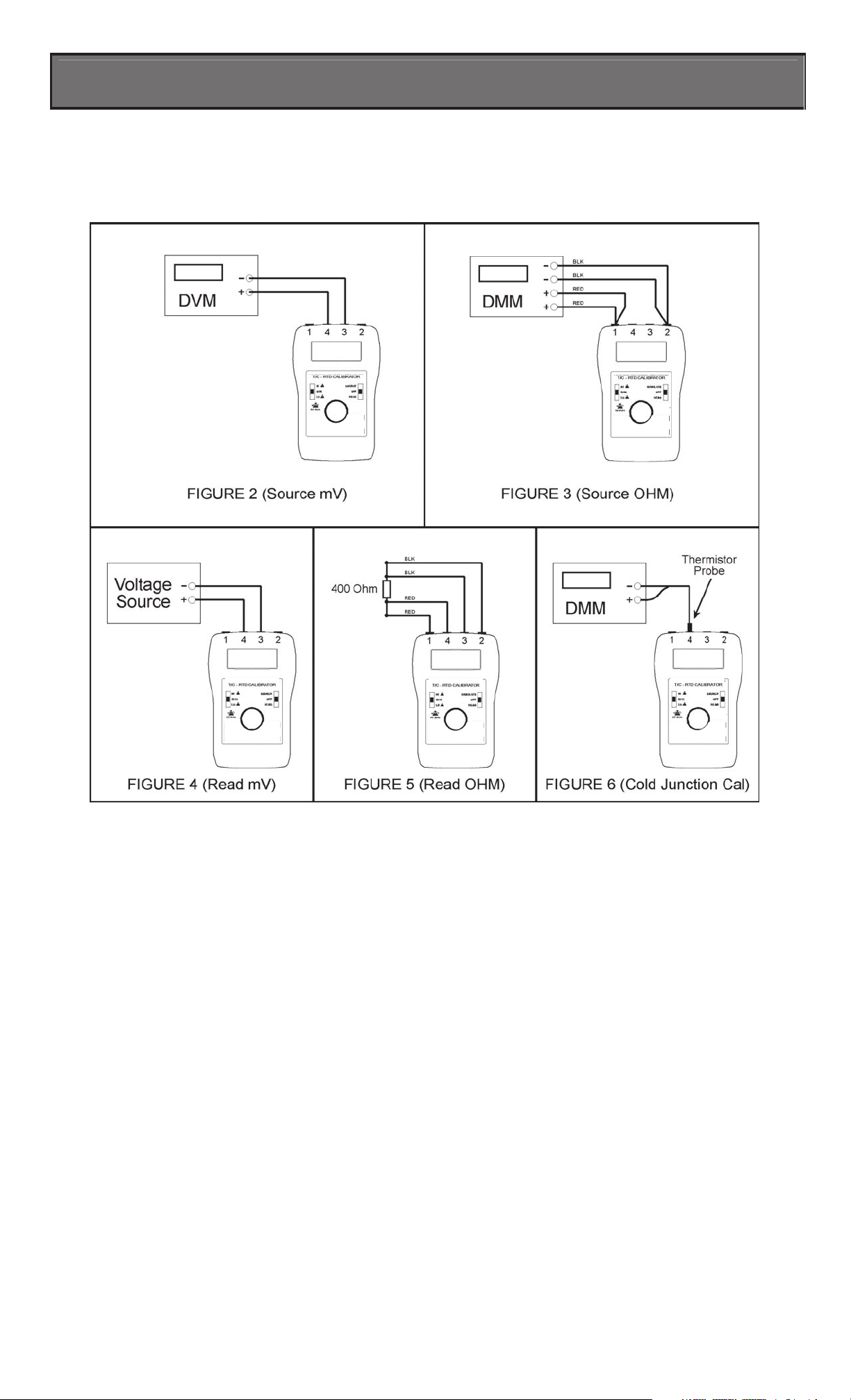
Connect the CL543 (two inner terminals) to a Voltage Meter (See Figure 2).
CL543 Field Calibration Prcedure
LO Calibration:
1. Slide the EZ-Check™ Switch to the LO position indicated by displaying “DIAL TO
0.000 mV” on the bottom of the LCD.
2. Dial the CL543 so the meter reads 0.000 mV.
3. Press the EZ-Dial™ Knob down.
4. The display will flash “STORE” to confirm that the value was stored.
HI Calibration:
1. Slide the EZ-Check™ Switch to the HI position indicated by displaying “DIAL TO
80.000 mV” on the bottom of the LCD.
2. Dial the CL543 so the meter reads 80.000 mV.
3. Press the EZ-Dial™ Knob down.
4. The display will flash “STORE” to confirm that the value was stored.
Simulate Ω Calibration:
Switch the CL543 to Simulate RTD Mode by double-clicking the EZ-Dial™ Knob.
Connect the CL543 (two inner terminals) to an OHM Meter in four-wire configuration
(See Figure 3).
LO Calibration:
5. Slide the EZ-Check™ Switch to the LO position indicated by displaying “DIAL TO
0.000 Ω” on the bottom of the LCD.
6. Dial the CL543 so the meter reads 0.000 Ω.
7. Press the EZ-Dial™ Knob down.
8. The display will flash “STORE” to confirm that the value was stored.
Page 9

9-12
CL543 Field Calibration Prcedure
HI Calibration:
5. Slide the EZ-Check™ Switch to the DIAL position indicated by displaying “DIAL TO
MATCH DMM” on the bottom of the LCD and the number 470.000 displayed.
6. Dial the CL543 so the UUT matches the reading on the DMM.
7. Press the EZ-Dial™ Knob down.
8. The display will flash “STORE” to confirm that the value was stored.
Middle Calibration:
9. Slide the EZ-Check™ Switch to the HI position indicated by displaying “DIAL TO
MATCH DMM” on the bottom of the LCD and the number 015.000 displayed.
10. Dial the CL543 so the UUT matches the reading on the DMM.
11. Press the EZ-Dial™ Knob down.
12. The display will flash “STORE” to confirm that the value was stored.
Read mV Calibration:
Switch the CL543 into READ Mode.
Connect the CL543 (two inner terminals) to a DC Voltage Source (See Figure 4).
LO Calibration:
1. Slide the EZ-Check™ switch to the LO position indicated by displaying “APPLY
0.000 mV” on the bottom of the LCD.
2. Set the voltage source to 0.000 mV.
3. Press the EZ-Dial™ Knob down
4. The display will flash “STORE” to confirm that the value was stored.
HI Calibration:
1. Slide the EZ-Check™ switch to the HI position indicated by displaying “APPLY
80.000 mV” on the bottom of the LCD.
2. Set the voltage source to 80.000 mV.
3. Press the EZ-Dial™ Knob down
4. The display will flash “STORE” to confirm that the value was stored.
Read Ω Calibration:
Switch the CL543 to Read RTD Mode by double-clicking the EZ-Dial™ Knob.
LO Calibration:
1. Slide the EZ-Check™ Switch to the LO position indicated by displaying “APPLY
0.000 Ω” on the bottom of the LCD.
2. Short all 4 input terminals of the UUT.
3. Press the EZ-Dial™ Knob down.
4. The display will flash “STORE” to confirm that the value was stored. The UUT will
then display “Please Wait…” while it automatically takes measurements for 2-wire, 3wire, and 4-wire. Do not make any changes during this time! Once the UUT has
completed the auto-cal, proceed to the next step.
HI Calibration:
1. Slide the EZ-Check™ Switch to the HI Position indicated by displaying “APPLY
400.000 Ω” on the left side of the LCD.
2. Connect a precision 400 Ω standard resistor to all 4 input terminals (See Figure 5).
3. Press the EZ-Dial™ Knob down.
4. The display will flash “STORE” to confirm that the value was stored. The UUT will
then display “Please Wait…” while it automatically takes measurements for 2-wire, 3wire, and 4-wire. Do not make any changes during this time! Once the UUT has
completed the auto-cal, proceed to the next step.
Page 10
10-12
CL543 Field Calibration Prcedure
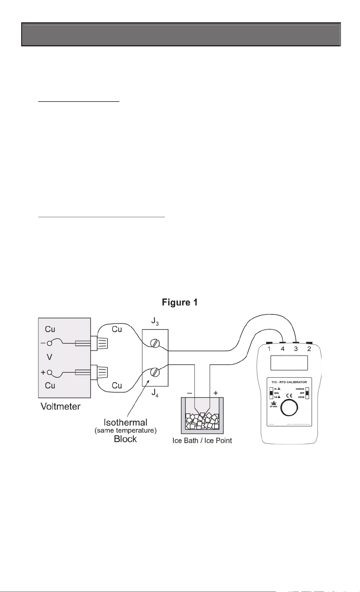
Cold Junction Calibration:
Double click the EZ-Dial™ Knob to enter the Cold Junction Calibration Mode. Slide the EZCheck™ Switch to either the HI or LO position. “COLD JUNCTION” will appear on the top of the
LCD.
Using a Thermistor Probe:
1. Connect the thermistor probe to the brass block marked ‘4W’ (which is
thermally-bonded to the temperature sensor and the Omega© connector. (See Figure 6).
2. Connect the other side of the thermistor probe to the OHM meter.
3. Let the temperature settle for 15minutes.
4. Check the Cold Junction Temperature on the top right of the LCD with the temperature
reading of the thermistor probe.
5. If the reading is out of specification then dial the EZ-Dial™ to the temperature reading
from the thermistor probe.
6. Press the EZ-Dial™ Knob down.
7. The display will flash “STORE” to confirm that the value was stored.
8. Verify the UUT (bottom right side of the LCD) Cold Junction Temperature is tracking
with the temperature reading of the thermistor probe. For best results, place the UUT in
a draft-free environment, away from air conditioners and/or heaters.
Using an Ice Bath or Ice Point Calibrator:
1. Connect the CL543 as shown in Figure 1.
2. Let the temperature settle for 15 minutes.
3. Check the Cold Junction Temperature on the top right of the LCD to the voltage reading
on the DVM and T/C chart.
4. If the reading is out of Specification then dial the EZ-Dial™ to the correct reading from
the DVM and T/C chart.
5. Press the EZ-Dial™ Knob down.
6. The display will flash “STORE” to confirm that the value was stored.
7. Verify the UUT (bottom right side of the LCD) Cold Junction Temperature is tracking
with the temperature reading of the DVM and T/C Table
CL543
Page 11
11-12
CL543 Field Calibration Prcedure
Completion of Calibration:
Turn the CL543 OFF. Next time the unit is turned on the CL543 will be calibrated and in
normal operational mode.
CL543
CL543
CL543
CL543
CL543
Page 12

CL543 Operating Instructions
NOTES:
It is the policy of OMEGA Engineering, Inc. to comply with all worldwide safety and EMC/EMI regulations that apply. OMEGA is constantly pursuing certification of its
products to the European New Approach Directives. OMEGA will add the CE mark to every appropriate device upon certification.
The information contained in this document is believed to be correct, but OMEGA accepts no liability for any errors it contains, and reserves the right to alter specifications without notice.
WARNING: These products are not designed for use in, and should not be used for, human applications.
WARRANTY/DISCLAIMER
OMEGA ENGINEERING, INC. warrants this unit to be free of defects in materials and workmanship for a period of 37 months from date of purchase.
OMEGA’s WARRANTY adds an additional one (1) month grace period to the normal three (3) year product warranty to cover handling and
shipping time. This ensures that OMEGA’s customers receive maximum coverage on each product.
If the unit malfunctions, it must be returned to the factory for evaluation. OMEGA’s Customer Service Department will issue an Authorized Return (AR)
number immediately upon phone or written request. Upon examination by OMEGA, if the unit is found to be defective, it will be repaired or replaced
at no charge. OMEGA’s WARRANTY does not apply to defects resulting from any action of the purchaser, including but not limited to mishandling,
improper interfacing, operation outside of design limits, improper repair, or unauthorized modification. This WARRANTY is VOID if the unit shows
evidence of having been tampered with or shows evidence of having been damaged as a result of excessive corrosion; or current, heat, moisture or
vibration; improper specification; misapplication; misuse or other operating conditions outside of OMEGA’s control. Components in which wear is not
warranted, include but are not limited to contact points, fuses, and triacs.
OMEGA is pleased to offer suggestions on the use of its various products. However, OMEGA neither assumes responsibility for any omissions
or errors nor assumes liability for any damages that result from the use of its products in accordance with information provided by OMEGA,
either verbal or written. OMEGA warrants only that the parts manufactured by the company will be as specified and free of defects. OMEGA
MAKES NO OTHER WARRANTIES OR REPRESENTATIONS OF ANY KIND WHATSOEVER, EXPRESSED OR IMPLIED, EXCEPT THAT OF TITLE,
AND ALL IMPLIED WARRANTIES INCLUDING ANY WARRANTY OF MERCHANTABILITY AND FITNESS FOR A PARTICULAR PURPOSE ARE
HEREBY DISCLAIMED. LIMITATION OF LIABILITY: The remedies of purchaser set forth herein are exclusive, and the total liability of OMEGA
with respect to this order, whether based on contract, warranty, negligence, indemnification, strict liability or otherwise, shall not exceed the
purchase price of the component upon which liability is based. In no event shall OMEGA be liable for consequential, incidental or special damages.
CONDITIONS: Equipment sold by OMEGA is not intended to be used, nor shall it be used: (1) as a “Basic Component” under 10 CFR 21 (NRC), used in
or with any nuclear installation or activity; or (2) in medical applications or used on humans. Should any Product(s) be used in or with any nuclear
installation or activity, medical application, used on humans, or misused in any way, OMEGA assumes no responsibility as set forth in our basic
WARRANTY/ DISCLAIMER language, and, additionally, purchaser will indemnify OMEGA and hold OMEGA harmless from any liability or damage
whatsoever arising out of the use of the Product(s) in such a manner.
Servicing North America:
U.S.A.: One Omega Drive, Box 4047
ISO 9001 Certified Stamford, CT 06907-0047
Tel: (203) 359-1660
FAX: (203) 359-7700
e-mail: [email protected]
Canada: 976 Bergar
Laval (Quebec) H7L 5A1, Canada
Tel: (514) 856-6928
FAX: (514) 856-6886
e-mail: [email protected]
For immediate technical or application assistance:
U.S.A. and Canada: Sales Service: 1-800-826-6342/1-800-TC-OMEGA
®
Customer Service: 1-800-622-2378/1-800-622-BEST
®
Engineering Service: 1-800-872-9436/1-800-USA-WHEN
®
Mexico: En Espan˜ol: (001) 203-359-7803
FAX: (001) 203-359-7807
e-mail:[email protected]
[email protected]
OMEGAnet®Online Service Internet e-mail
omega.com [email protected]
Servicing Europe:
Czech Republic: Frystatska 184, 733 01 Karviná, Czech Republic
Tel: +420 (0)59 6311899
FAX: +420 (0)59 6311114
Toll Free: 0800-1-66342
e-mail: [email protected]
Germany/Austria: Daimlerstrasse 26, D-75392 Deckenpfronn, Germany
Tel: +49 (0)7056 9398-0
FAX: +49 (0)7056 9398-29
Toll Free in Germany: 0800 639 7678
e-mail: [email protected]
United Kingdom: One Omega Drive, River Bend Technology Centre
ISO 9002 Certified Northbank, Irlam, Manchester
M44 5BD United Kingdom
Tel: +44 (0)161 777 6611
FAX: +44 (0)161 777 6622
Toll Free in United Kingdom: 0800-488-488
e-mail: [email protected]
RETURN REQUESTS / INQUIRIES
Direct all warranty and repair requests/inquiries to the OMEGA Customer Service Department. BEFORE RETURNING ANY PRODUCT(S) TO
OMEGA, PURCHASER MUST OBTAIN AN AUTHORIZED RETURN (AR) NUMBER FROM OMEGA’S CUSTOMER SERVICE DEPARTMENT (IN ORDER
TO AVOID PROCESSING DELAYS). The assigned AR number should then be marked on the outside of the return package and on any
correspondence.
The purchaser is responsible for shipping charges, freight, insurance and proper packaging to prevent breakage in transit.
FOR W
ARRANTY RETURNS, please have the following information
available BEFORE contacting OMEGA:
1. Purchase Order number under which the product was PURCHASED,
2. Model and serial number of the product under warranty, and
FOR NON-WARRANTY REPAIRS,
consult OMEGA for current repair charges.
Have the following information available BEFORE contacting OMEGA:
1. Purchase Order number to cover the COST of the repair,
2. Model and serial number of the product, and
3. Repair instructions and/or specific problems relative to the product.
OMEGA’s policy is to make running changes, not model changes, whenever an improvement is possible. This affords our customers the latest in technology and engineering. OMEGA is a registered trademark of OMEGA ENGINEERING, INC.
© Copyright 2006 OMEGA ENGINEERING, INC. All rights reserved. This document may not be copied, photocopied, reproduced, translated, or reduced to any electronic
medium or machine-readable form, in whole or in part, without the prior written consent of OMEGA ENGINEERING, INC.
 Loading...