

Page 1
omega.com
e-mail: [email protected]
For latest product manuals:
omegamanual.info
User’s Guide
CL542-PLUS
Automated
Thermocouple Calibrator
®
MADE IN
Shop online at
Page 2

Servicing North America:
U.S.A.: Omega Engineering, Inc., One Omega Drive, P.O. Box 4047
ISO 9001 Certified
Stamford, CT 06907-0047
Toll-Free: 1-800-826-6342 Tel: (203) 359-1660
FAX: (203) 359-7700 e-mail: [email protected]
Canada: 976 Bergar
Laval (Quebec), H7L 5A1 Canada
Toll-Free: 1-800-826-6342 TEL: (514) 856-6928
FAX: (514) 856-6886 e-mail: [email protected]
For immediate technical or application assistance:
U.S.A. and Canada: Sales Service: 1-800-826-6342/1-800-TC-OMEGA
®
Customer Service: 1-800-622-2378/1-800-622-BEST
®
Engineering Service: 1-800-872-9436/1-800-USA-WHEN
®
Mexico En Español: 001 (203) 359-7803 FAX: 001 (203) 359-7807
Latin America [email protected] e-mail: [email protected]
Servicing Europe:
Benelux: Managed by the United Kingdom Office
Czech Republic: Frystatska 184
733 01 Karviná, Czech Republic
Toll-Free: 0800-1-66342 TEL: +420-59-6311899
FAX: +420-59-6311114 e-mail: [email protected]
France: Managed by the United Kingdom Office
Toll-Free: 0800 466 342 TEL: +33 (0) 161 37 29 00
FAX: +33 (0) 130 57 54 27 e-mail: [email protected]
Germany/Austria: Daimlerstrasse 26
D-75392 Deckenpfronn, Germany
Toll-Free: 0800 6397678 TEL: +49 (0) 7056 9398-0
FAX: +49 (0) 7056 9398-29 e-mail: [email protected]
United Kingdom: OMEGA Engineering Ltd.
ISO 9001 Certified
One Omega Drive, River Bend Technology Centre, Northbank
Irlam, Manchester M44 5BD United Kingdom
Toll-Free: 0800-488-488 TEL: +44 (0) 161 777-6611
FAX: +44 (0) 161 777-6622 e-mail: [email protected]
OMEGAnet®Online Service Internet e-mail
omega.com [email protected]
It is the policy of OMEGA Engineering, Inc. to comply with all worldwide safety and EMC/EMI
regulations that apply. OMEGA is constantly pursuing certification of its products to the European New
Approach Directives. OMEGA will add the CE mark to every appropriate device upon certification.
The information contained in this document is believed to be correct, but OMEGA accepts no liability for any
errors it contains, and reserves the right to alter specifications without notice.
WARNING: These products are not designed for use in, and should not be used for, human applications.
Page 3

Product Description
• Easy to use
With the CL542-PLUS you can check & calibrate all
your thermocouple instruments and measure
thermocouple sensors.
NEW
• Take it without into the shop, plant or field
Carry it without worry - it comes protected with a
rubber boot and rugged, low profile switch. Easy to
operate even in the dark areas of the plant with the
backlit display.
• Calibrate directly in temperature (°C & °F)
Stop carrying around a millivolt source and thermocouple tables. The CL542-PLUS works with the
thermocouples you use including types J, T, E, K, R,
S, B, N, G, C, D, L (J-DIN), U (T-DIN) and Platinel II.
Easily set any value quickly to within 0.1° with the
adjustable digital potentiometer “DIAL” plus store any
three temperatures for instant recall with the
OMEGA switch.
• Calibrate quickly with automatic output stepping
Choose between 2, 3, 5, 11 and 21 steps to
automatically increment the output in 100%, 50%,
25%, 10% or 5% of span. Select the step time to
match your system from 5, 6, 7, 8, 10, 15, 20, 25, 30
and 60 seconds.
• Compatible with all process instruments
Connect directly to the thermocouple inputs of smart
transmitters, PLCs, DCS and multichannel recorders
and verify their outputs or displays.
• Measure Thermocouple Sensors
Trouble shoot sensor connections and find broken wires. The CL542-PLUS measures the
thermocouple in degrees C or F. Secondary display shows the millivolt value corresponding to
the thermocouple temperature as well as the cold junction temperature measured by the
calibrator.
PICTURE
Page 1
Page 4
Basic Operation
CL542-PLUS
17.332mV 22.4°C
HI
422.1
TYPE K °C
AUTOMATED THERMOCOUPLE
CAL IBRATOR
J, T, E, K, R, S, B, N, G, C, D, L, U, mV
SET
OVERLOAD
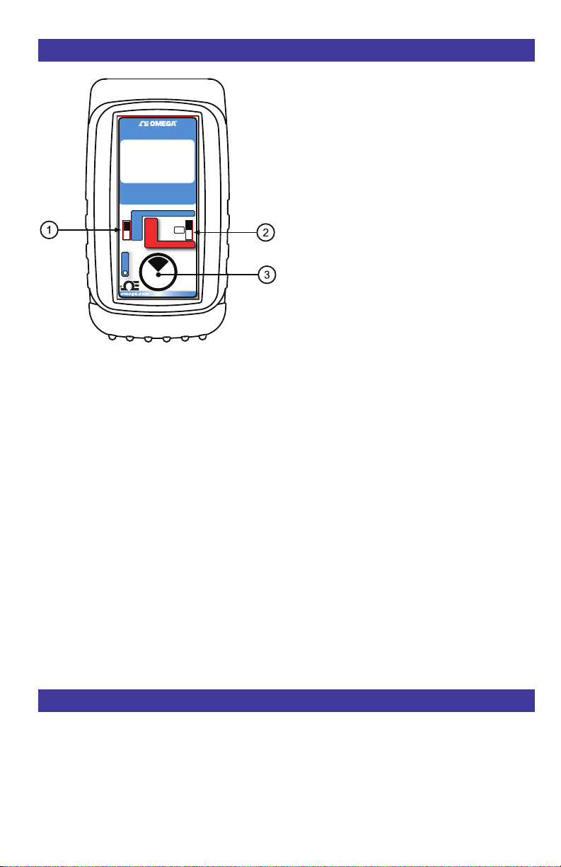
1 OMEGA SWITCH
SOURCE: Instantly output two preset thermocouple
tem p e r a tures b y moving t h e Omega s w itch t o
the “LO” position or “HI” position.
point checks select the “DIAL” position. The
CL542-PLUS will remember the last “DIAL”
value, even with the power off.
These values can easily be changed to suit the
calibration requirements. The temperatures stored in
the HI and LO positions are also used for Auto
Stepping.
READ: Slide the switch to the DIAL position. The
CL542-PLUS
will display the current temperature from
the thermocouple sensor. Slide the switch to HI and
the highest temperature measured since turn-on or
reset will be displayed; slide the switch to LO and the
lowest temperature measured since turn-on or reset
will be displayed.
SOURCE
MAX
HI
READ
OFF
MIN
LO
READ
Push & Turn
Fast Dialing
Push & Hold
Store/Step
Double Click
for Options
for
to
For fast three
2 SOURCE/OFF/READ Switch
Select “SOURCE .stlovillim ro ,F° ,C° ni tuptuo ot ”
Select “READ” to read a thermocouple sensor
or millivolts.
3 PUSH-BUTTON KNOB
SOURCE: Turn the knob to adjust the output
level. Turn clockwise to increase the output,
steps at a time. Push down and turn the
PUSH-BUTTON knob for faster dialing.
Press and hold the knob for two seconds to store
de sire d OM EGA HI/ L O p oint s in SO U RCE
mode. Continue to press and hold the knob for
two more seconds to start the automatic
ramping.
READ: Press and hold to transfer the current
temp erature into t he OM EGA HI/ LO po in ts.
This clears the HI/LO temperature readings
which will update as the temperature changes.
Double click the knob to get into the CL542-PLUS
Configuration Mode. Use configuration to select
°C or °F, T/C Type, Backlight On/Off, Step Size,
Step Time and Auto Off On/Off.
CHANGING BATTERIES
Low battery is i
ndicated by “BAT” on the display.
Approximately one to four hours of typical
operation remain before the CL542-PLUS will
automatically turn off. To change the batteries;
remove the rubber boot, remove the battery door
from the back of the unit by sliding the door
downward. This allows access to the battery
compartment. Replace with four (4) “AA” 1.5V
batteries being careful to check the polarity.
Replace the battery door and replace the boot. All
stored configuration options (T/C Type,
OMEGA Memories, etc., are reset to factory
settings when the batteries are removed.
°1.0 ni tuptuo eht esaerced ot esiwkcolc retnuoc
Connections
Simulating or reading thermocouples requires
the use of thermocouple or extension grade
thermocouple wire.
Plug thermocouple wires into the female
miniature thermocouple connector mounted in
the top end of the housing.
Page 2
Note: A
lkaline batteries are supplied and
recommended for maximum battery life and
performance.
The CL542-PLUS has two banana jacks mounted
in the top end of the housing. These are not
temperature compensated and are to be used
only for millivolt signals.
Page 5

Configuration
Configure the Calibrator
Move 2
“READ”.
Setup
Double click the
time the unit is on and the following displays will
appear for 15 seconds:
POWER SWITCH to “SOURCE” or
MODEL CL542-PLUS
DOUBLE CLICK
PUSH-BUTTON KNOB
FOR CONFIGURATION
3 PUSH-BUTTON knob at any
> EXIT 15
TEMP UNITS °C
T/C K
CJC ON
BACKLIGHT ON
> EXIT 15
STEPS 3
STEP TIME 8
AUTO OFF ON
TEMP UNITS - pressing the knob will toggle
between °C and °F.
T/C - pressing the knob will cycle through T/C
types J, T, E, K, R, S, B, N, G, C, D, L (J-DIN), U
(T-DIN) and Platinel II.
CJC - Automatic CJC (Cold Junction
Compensation) may be turned on or off. It is
recommended that CJC be left on (default). CJC
should only be turned off if an external cold
junction compensator or ice bath is used with
the CL542-PLUS.
BACKLIGHT - If BACKLIGHT is ON the
backlight will light all the time the unit is powered
up. For maximum battery life turn the backlight
off when using the calibrator in areas with
enough ambient light to read the display.
STEPS - pressing the knob will cycle through 2,
3, 5, 11 and 21 steps. The endpoints of the steps
are based on
OMEGA outputs.
STEP TIME - pressing the knob will cycle
through 5, 6, 7, 8, 9, 10, 15, 20, 25, 30 and 60
seconds.
the values stored in the HI and LO
> EXIT 15
SH
OW mV ON
SHOW CJ ON
Turn the
through the menu. Press the 3 PUSH-BUTTON
kn ob to tog gle bet wee n O FF and ON or to
sc roll through the settings.
EXIT MENU - exits this menu immediately and
saves any changes. Menu will automatically exit
after 15 seconds of inactivity (countdown timer is
displayed).
3 PUSH- BUTTON knob to move
AUTO OFF - If AUTO OFF is ON, the unit will
turn off after 30 minutes of inactivity to save
battery life. If AUTO OFF is OFF the unit will stay
on until the POWER SWITCH is moved to the off
position.
SHOW mV - If SHOW mV is ON the mV value
corresponding to the sourced or measured
temperature is displayed.
SHOW CJ - If SHOW CJ is ON the cold junction
temperature measured by the CL542-PLUS will
be displayed.
Note: All settings are remembered even with the
power off. Removing the batteries resets the
values to factory defaults.
Page 3
Page 6
Sourcing Thermocouple
SOURCE
Choose this function to provide a simulated thermocouple signal into controllers, temperature
transmitters, indicators or any input devices that measure thermocouple sensors..
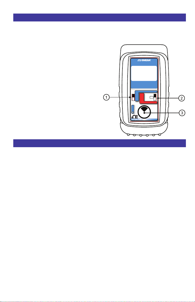
1) Disconnect the thermocouple sensor from the
device to be calibrated.
2) Select “SOURCE” with slide switch
3) Connect a thermocouple wire (matching the type
of wire to sensor being simulated) with miniature
male T/C connector to the inputs of the device
being calibrated, making sure to check polarity.
Millivolt outputs (without cold junction) may be
connected with a copper (white) miniature T/C
connector or the banana jacks with copper wire.
The output is adjusted in 0.1° (or 0.001 mV)
increments by turning the knob 3 while the
OMEGA switch
1 is in the “HI”, “LO” or “SET”
position. Press and turn the knob for faster dialing
with 10° (or 0.100) increment
s.
2.
CL542-PLUS
17.332mV 22.4°C
HI
422.1
TYPE K °C
AUTOMATED THERMOCOUPLE
CAL IBRATOR
J, T, E, K, R, S, B, N, G, C, D, L, U, mV
SET
OVERLOAD
SOURCE
MAX
HI
READ
OFF
MIN
LO
READ
Push & Turn
Fast Dialing
Push & Hold
Store/Step
Double Click
for Options
for
to
The OVERLOAD indicator will light if excessive
voltage or current is detected by the calibrator.
Reading Thermocouple Sensors
READ
Choose this function to measure temperatures with a thermocouple probe or sensor.
1) Disconnect the thermocouple sensor from any other device.
2) Select “READ” with slide switch 3.
3) Place the OMEGA switch into the READ position.
4) Connect a thermocouple probe (matching the type of wire to sensor being measured) with miniature male T/C connector to the sensor. Millivolt outputs (without cold junction) are connected
with a copper (white) miniature thermocouple connector or to the banana jacks with cooper wire.
The CL-542-PLUS measures the temperature signal and constantly updates the display with the
current temperature reading. Move the OMEGA switch to MAX to see the highest temperature
reading and to MIN to see the lowest temperature reading. Press and hold the knob
e to clear the
MAX and MIN readings.
The OVERLOAD indicator will light if excessive voltage or current is detected by the calibrator.
Page 4
Page 7

Storing OMEGA Outputs
STORING HI and LO OMEGA Outputs
Choose this function to provide a simulated thermocouple signal into controllers, temperature
transmitters, indicators or any other input device that measure thermocouple sensors..
1) Store your high (SPAN) output temperature by moving the OMEGA switch to the HI position
and turn the 3 PUSH-BUTTON knob until the desired temperature is on the display. Press and
hold the knob until STORED appears to store the value. Release the PUSH-BUTTON knob.
2) Store your low (ZERO) output temperature by moving the OMEGA switch to the LO position
and turn the
the PUSH-BUTTON knob until STORED appears to store the value. Release the PUSH-BUTTON knob.
3) Instantly output your SPAN and ZERO temperature outputs by moving the OMEGA switch
between HI and LO. You may also select any third temperature output (such as mid-range) using
the SET position on the OMEGA switch.
3 PUSH-BUTTON knob until the desired temperature is on the display. Press and hold
Automatic Stepping
To change the Automatic Stepping settings
Double click the 3 PUSH-BUTTON knob at any time the unit is on and the following display will
appear for 30 seconds:
Turn the
Press the 3 PUSH-BUTTON knob to toggle between OFF
and ON or to change the STEPS and the STEP TIME settings.
These settings are remembered even with the power off.
EXIT MENU - exits this menu immediately and saves any
changes. Menu will automatically exit after 30 seconds of
inactivity.
3 PUSH-BUTTON knob to move through the menu.
EXIT 15
> STEPS 3
STEP TIME 8
AUTO OFF ON
STEPS - pressing the knob will cycle through 2, 3, 5, 11 and 21 steps then reverse dircetion. The
endpoints of the steps are based on the values stored in the HI and LO OMEGA outputs.
2 steps will automatically switch between the values stored in the HI & LO OMEGA (0 &
100%).
3 steps between the HI, Midpoint and LO OMEGA (0, 50 & 100%).
5 steps between the HI and LO OMEGA in 25% increments (0, 25,
11 steps between the HI and LO OMEGA in 10% increments (0, 10, 20...80, 90 &100%).
21 steps between the HI and LO OMEGA in 5% increments (0, 5, 10... 90, 95 & 100%).
STEP TIME - pressing the knob will cycle through 5, 6, 7, 8, 9, 10, 15, 20, 25, 30 and 60 seconds.
To start the Automatic Stepping
Start automatic stepping or ramping by placing the OMEGA Switch into the HI or LO position
then press and hold the
the display after 3 seconds and continue to press the PUSH-BUTTON knob) until the word
STEPPING appears on the display. The word STEPPING will appear on the display anytime the
selected automatic function is running. Stop the stepping by again pressing and holding the
PUSH-BUTTON knob for 3 seconds.
3 PUSH-BUTTON knob for 6 seconds (the word STORE will appear on
50, 75 & 100%).
3
Page 5
Page 8

Ranges & Accuracies
T/C
Type
Degrees C
Range
J -200.0 to -180.0 ±0.3° -346.0 to -292.0 ±0.5° +Iron
-180.0 to -50.0 ±0.2° -292.0 to -58.0 ±0.4°
-50.0 to 500.0 ±0.1° -58.0 to 932.0 ±0.2°
500.0 to 1200,0 ±0.2° 932.0 to 2192.0 ±0.4°
Accuracy Degrees F
Range
Accuracy T/C
Material
-Connstantan
Jacket
ISA/ANSI
Color
White
Red
Black
K -230.0 to -100.0 ±0.6° -382.0 to -148.0 ±1.1° + Chromel®
-100.0 to 1050.0 ±0.2° -148.0 to 1922.0 ±0.4°
1050.0 to 1371.1 ±0.3° 1922.0 to 2500.0 ±0.5°
T -260.0 to -200.0 ±1.0° -436.0 to -328.0 ±1.8° +Copper
-200.0 to -50.0 ±0.5° -328.0 to -58.0 ±0.9°
-50.0 to 0.0 ±0.2° -58.0 to 32.0 ±0.4°
0.0 to 400.0 ±0.1° 32.0 to 752.0 ±0.2°
E -240.0 to -200.0 ±0.4° -400.0 to -328.0 ±0.7° +Chromel
-200.0 to -100.0 ±0.2° -328.0 to -148.0 ±0.4°
-100.0 to 850.0 ±0.1° -148.0 to 1562.0 ±0.2°
850.0 to 1000.0 ±0.2° 1562.0 to 1832.0 ±0.4°
R -13.3 to 250.0 ±1.2° -1.0 to 482.0 ±2.2° +Pt/13Rh
250.0 to 750.0 ±0.6° 482.0 to 1382.0 ±1.1°
750.0 to 1600.0 ±0.5° 1382.0 to 2192.0 ±0.9°
1600.0 to 1767.8 ±0.6° 2192.0 to 3214.0 ±1.1°
S -18.3 to 100.0 ±1.2° -1.0 to 212.0 ±2.1° +Pt/10Rh
100.0 to 400.0 ±0.8° 212.0 to 752.0 ±1.4°
400.0 to 1700.0 ±0.6° 752.0 to 3092.0 ±1.1°
1700.0 to 1767.8 ±0.7° 3092.0 to 3214.0 ±1.3°
-Alumel®
Jacket
-Constantan
Jacket
-Constantan
Jacket
-Platinum
Jacket
-Platinum
Jacket
Yellow
Red
Yellow
Blue
Red
Blue
Purple
Red
Purple
Black
Red
Green
Black
Red
Green
B 315.6 to 550.0 ±1.8° 600 to 1022.0 ±3.2° +Pt/30Rh
550.0 to 900.0 ±1.1° 1022.0 to 1652.0 ±2.0°
900.0 to 1150.0 ±0.7° 1652.0
1150.0 to 1820.0 ±0.6° 2102.0 to 3308.0 ±1.1°
to 2102.0 ±1.3°
Page 6
-Pt/6Rh
Jacket
Grey
Red
Grey
Page 9

Ranges & Accuracies
T/C
Type
(W)
(W5)
Degrees C
Range
N -230.0 to -180.0 ±1.0° -382.0 to -292.0 ±1.8° +Nicrosil
-180.0 to -50.0 ±0.5° -292.0 to -58.0 ±0.9°
-50.0 to 1100.0 ±0.2° -58.0 to 2012.0 ±0.4°
1100.0 to 1300.0 ±0.3° 2012.0 to 2372.0 ±0.5°
G
100.0 to 150.0 ±1.2° 212.0 to 302.0 ±2.2° +Tungsten
150.0 to 400.0 ±0.8° 302.0 to 752.0 ±1.4°
400.0 to 1700.0 ±0.4° 752.0 to 3092.0 ±0.7°
1700.0 to 2320.0 ±0.7° 3092.0 to 4208.0 ±1.3°
C
-1.1 to 1500 ±0.5° 30.0 to 2372.0 ±0.9° +W5/Re
1500 to 1900 ±0.6° 2372.0 to 3452.0 ±101°
1900.0 to 2100.0 ±0.7° 3452.0 to 3812.0 ±1.3°
2100.0 to 2320.0 ±0.9° 3812.0 to 4208.0 ±1.6°
Accuracy Degrees F
Range
Accuracy T/C
Material
-Nisil
Jacket
-W26/Re
Jacket
-W26/Re
Jacket
ISA/ANSI
Color
Orange
Red
Orange
White
Red
White/Blue
White
Red
White/Red
D -1.0 to 50.0 ±0.6° 30.0 to 122.0 ±1.1° +W3/Re
50.0 to 1400.0 ±0.4° 122.0 to 2552.0 ±0.7°
1400.0 to 1800.0 ±0.5° 2552.0 to 3272.0 ±0.9°
1800.0 to 2320.0 ±0.9° 3272.0 to 4208.0 ±1.6°
-217.8 to -150.0 ±0.6° -360.0 to -238.0 ±1.1°
P
Platinel®
-150.0 to -50.0 ±0.4° -238.0 to -58.0 ±0.7°
-50.0 to 1000.0 ±0.2° -58.0 to 1832.0 ±0.4°
1000.0 to 1395.0 ±0.3° 1832.0 to 2543.0 ±0.5°
DIN Colors
L
-200.0 to -50.0 ±0.2° -328.0 to -58.0 ±0.4° +Iron
J-DIN
T-DIN
-50.0 to 500.0 ±0.1° -58.0 to 932.0 ±0.2°
500.0 to 750.0 ±0.2° 932.0 to 1382.0 ±0.4°
U
-200.0 to -75.0 ±0.3° -328.0 to -103.0 ±0.5° +Copper
-75.0 to 100.0 ±0.2° -103.0
100.0 to 600.0 ±0.1° 212.0 to 1112.0 ±0.2°
to 212.0 ±0.4°
-W25/Re
Jacket
+Pd55/Pt31/Au14
-Au65/Pd35
Jacket
-Connstantan
Jacket
-Constantan
Jacket
White
White/Yellow
Yellow
Black
Blue
Blue
Brown
Brown
Red
Red
Red
Red
Page 7
Page 10

CL-542-PLUS Specifications
(Unless otherwise indicated all specifications are rated from a nominal 23°C,
General
Accuracy ±(0.008% of Reading + 0.006 mV)
Cold Junction Compensation ± 0.16°F (±0.1°C)
Millivolt Range -13.000 to 80.000 mV
Operating Temperature Range -25 to 60°C (-10 to 140°F)
Relative Humidity Range 10% ≤RH ≤90% (0 to 35°C), Non-condensing
Size L=5.63 x W=3.00 x H=1.60 inches
Weight 12.1 ounces (including boot & batteries)
Batteries Four “AA” Alkaline 1.5V (LR6)
Battery Life 50 Hours
Low Battery Low battery indication with nominal 1 hour of life left
Protection against misconnection Over-voltage protection to 60 Vdc (rated for 30 seconds)
Display High contrast graphic liquid crystal display. LED backlighting
Read
Input Impedance
Open Thermocouple
Threshold
Pulse
Normal Mode Rejection 50/60 Hz, 50 dB
Common Mode Rejection 50/60 Hz, 120 dB
70% RH for 1 year from calibration)
10% ≤RH ≤70% (35 to 60°C), Non-condensing
for use in low lit areas.
>10 Megohms
10,000 Ohms nominal
<10 microamp pulse for 300 milliseconds
Source
Output Impedance <0.3 Ohms
Source Current >20 mA (drives 80 mV into 10 Ohms)
Noise ≤4 microvolts p-p for frequencies of 10 Hz or below
Accessories
Standard Test Leads (Included with calibrator)
Three feet (1 meter) of wire with an alligator clip on one end and a spring loaded
protected banana plug on the other end.
Page 8
Page 11

WARRANTY/DISCLAIMER
OMEGA ENGINEERING, INC. warrants this unit to be free of defects in materials and
workmanship for a period of 37 months from date of purchase. OMEGA’s WARRANTY adds
an additional one (1) month grace period to the normal three (3) year product warranty to
cover handling and shipping time. This ensures that OMEGA’s customers receive maximum
coverage on each product.
If the unit malfunctions, it must be returned to the factory for evaluation. OMEGA’s Customer
Service Department will issue an Authorized Return (AR) number immediately upon phone or
written request. Upon examination by OMEGA, if the unit is found to be defective, it will be
repaired or replaced at no charge. OMEGA’s WARRANTY does not apply to defects resulting
from any action of the purchaser, including but not limited to mishandling, improper
interfacing, operation outside of design limits, improper repair, or unauthorized modification.
This WARRANTY is VOID if the unit shows evidence of having been tampered with or shows
evidence of having been damaged as a result of excessive corrosion; or current, heat, moisture
or vibration; improper specification; misapplication; misuse or other operating conditions
outside of OMEGA’s control. Components in which wear is not warranted, include but are not
limited to contact points, fuses, and triacs.
OMEGA is pleased to offer suggestions on the use of its various products. However,
OMEGA neither assumes responsibility for any omissions or errors nor assumes
liability for any damages that result from the use of its products in accordance with
information provided by OMEGA, either verbal or written. OMEGA warrants only
that the parts manufactured by the company will be as specified and free of
defects. OMEGA MAKES NO OTHER WARRANTIES OR REPRESENTATIONS OF ANY
KIND WHATSOEVER, EXPRESSED OR IMPLIED, EXCEPT THAT OF TITLE, AND ALL
IMPLIED WARRANTIES INCLUDING ANY WARRANTY OF MERCHANTABILITY AND
FITNESS FOR A PARTICULAR PURPOSE ARE HEREBY DISCLAIMED. LIMITATION OF
LIABILITY: The remedies of purchaser set forth herein are exclusive, and the total
liability of OMEGA with respect to this order, whether based on contract, warranty,
negligence, indemnification, strict liability or otherwise, shall not exceed the
purchase price of the component upon which liability is based. In no event shall
OMEGA be liable for consequential, incidental or special damages.
CONDITIONS: Equipment sold by OMEGA is not intended to be used, nor shall it be used: (1)
as a “Basic Component” under 10 CFR 21 (NRC), used in or with any nuclear installation or
activity; or (2) in medical applications or used on humans. Should any Product(s) be used in or
with any nuclear installation or activity, medical application, used on humans, or misused in
any way, OMEGA assumes no responsibility as set forth in our basic WARRANTY/ DISCLAIMER
language, and, additionally, purchaser will indemnify OMEGA and hold OMEGA harmless from
any liability or damage whatsoever arising out of the use of the Product(s) in such a manner.
RETURN REQUESTS/INQUIRIES
Direct all warranty and repair requests/inquiries to the OMEGA Customer Service Department.
BEFORE RETURNING ANY PRODUCT(S) TO OMEGA, PURCHASER MUST OBTAIN AN
AUTHORIZED RETURN (AR) NUMBER FROM OMEGA’S CUSTOMER SERVICE DEPARTMENT
(IN ORDER TO AVOID PROCESSING DELAYS). The assigned AR number should then be
marked on the outside of the return package and on any correspondence.
The purchaser is responsible for shipping charges, freight, insurance and proper packaging to
prevent breakage in transit.
FOR WARRANTY
RETURNS, please have
the following information available BEFORE
contacting OMEGA:
1. Purchase Order number under which
the product was PURCHASED,
2. Model and serial number of the product
under warranty, and
3. Repair instructions and/or specific
problems relative to the product.
FOR NON-WARRANTY REPAIRS,
consult
OMEGA for current repair charges. Have the
following information available BEFORE
contacting OMEGA:
1. Purchase Order number to cover the
COST of the repair,
2. Model and serial number of theproduct, and
3. Repair instructions and/or specific problems
relative to the product.
OMEGA’s policy is to make running changes, not model changes, whenever an improvement is possible.
This affords our customers the latest in technology and engineering.
OMEGA is a registered trademark of OMEGA ENGINEERING, INC.
© Copyright 2010 OMEGA ENGINEERING, INC. All rights reserved. This document may not be copied, photocopied,
reproduced, translated, or reduced to any electronic medium or machine-readable form, in whole or in part, without
the prior written consent of OMEGA ENGINEERING, INC.
Page 12

Where Do I Find Everything I Need for
Process Measurement and Control?
OMEGA…Of Course!
Shop online at omega.com
SM
TEMPERATURE
䡺⻬
Thermocouple, RTD & Thermistor Probes, Connectors, Panels & Assemblies
䡺⻬
Wire: Thermocouple, RTD & Thermistor
䡺⻬
Calibrators & Ice Point References
䡺⻬
Recorders, Controllers & Process Monitors
䡺⻬
Infrared Pyrometers
PRESSURE, STRAIN AND FORCE
䡺⻬
Transducers & Strain Gages
䡺⻬
Load Cells & Pressure Gages
䡺⻬
Displacement Transducers
䡺⻬
Instrumentation & Accessories
FLOW/LEVEL
䡺⻬
Rotameters, Gas Mass Flowmeters & Flow Computers
䡺⻬
Air Velocity Indicators
䡺⻬
Turbine/Paddlewheel Systems
䡺⻬
Totalizers & Batch Controllers
pH/CONDUCTIVITY
䡺⻬
pH Electrodes, Testers & Accessories
䡺⻬
Benchtop/Laboratory Meters
䡺⻬
Controllers, Calibrators, Simulators & Pumps
䡺⻬
Industrial pH & Conductivity Equipment
DATA ACQUISITION
䡺⻬
Data Acquisition & Engineering Software
䡺⻬
Communications-Based Acquisition Systems
䡺⻬
Plug-in Cards for Apple, IBM & Compatibles
䡺⻬
Data Logging Systems
䡺⻬
Recorders, Printers & Plotters
HEATERS
䡺⻬
Heating Cable
䡺⻬
Cartridge & Strip Heaters
䡺⻬
Immersion & Band Heaters
䡺⻬
Flexible Heaters
䡺⻬
Laboratory Heaters
ENVIRONMENTAL
MONITORING AND CONTROL
䡺⻬
Metering & Control Instrumentation
䡺⻬
Refractometers
䡺⻬
Pumps & Tubing
䡺⻬
Air, Soil & Water Monitors
䡺⻬
Industrial Water & Wastewater Treatment
䡺⻬
pH, Conductivity & Dissolved Oxygen Instruments
M4838/0210
 Loading...