

Page 1
Software for CL427
Version V100531
omega.com
800
-DAS-IEEE (800-327-4333)
© COPYRIGHT 2012 OMEGA ENGINEERING, INC.
OMEGAnet®Online Service Internet e-mail
omega.com [email protected]
User’s Guide
Servicing North America:
U.S.A.: Omega Engineering, Inc., One Omega Drive, P.O. Box 4047
ISO 9001 Certified
Canada:
For immediate technical or application assistance:
U.S.A. and Canada:
Shop online at
omega.com
e-mail: [email protected]
For latest product manuals:
omegamanual.info
MADE IN TAIWAN
CL427
®
®
Mexico
Latin America [email protected] e-mail: [email protected]
Benelux:
Czech Republic: Frystatska 184
France: Managed by the United Kingdom Office
Germany/Austria: Daimlerstrasse 26
United Kingdom:
ISO 9001 Certified
Stamford, CT 06907-0047
Toll-Free: 1-800-826-6342 Tel: (203) 359-1660
FAX: (203) 359-7700 e-mail: [email protected]
976 Bergar
Laval (Quebec), H7L 5A1 Canada
Toll-Free: 1-800-826-6342 TEL: (514) 856-6928
FAX: (514) 856-6886 e-mail: [email protected]
Sales Service: 1-800-826-6342/1-800-TC-OMEGA
Customer Service: 1-800-622-2378/1-800-622-BEST
Engineering Service: 1-800-872-9436/1-800-USA-WHEN
En Español: 001 (203) 359-7803 FAX: 001 (203) 359-7807
®
®
®
Servicing Europe:
Managed by the United Kingdom Office
Toll-Free: 0800 099 3344 TEL: +31 20 347 21 21
FAX: +31 20 643 46 43 e-mail: [email protected]
733 01 Karviná, Czech Republic
Toll-Free: 0800-1-66342 TEL: +420-59-6311899
FAX: +420-59-6311114 e-mail: [email protected]
Toll-Free: 0800 466 342 TEL: +33 (0) 161 37 29 00
FAX: +33 (0) 130 57 54 27 e-mail: [email protected]
D-75392 Deckenpfronn, Germany
Toll-Free: 0800 6397678 TEL: +49 (0) 7056 9398-0
FAX: +49 (0) 7056 9398-29 e-mail: [email protected]
OMEGA Engineering Ltd.
One Omega Drive, River Bend Technology Centre, Northbank
Irlam, Manchester M44 5BD United Kingdom
Toll-Free: 0800-488-488 TEL: +44 (0) 161 777-6611
FAX: +44 (0) 161 777-6622 e-mail: [email protected]
Software for CL427
Documenting Multifunction Calibrator
and Arbitrary Function Generator
It is the policy of OMEGA Engineering, Inc. to comply with all worldwide safety and EMC/EMI
regulations that apply. OMEGA is constantly pursuing certification of its products to the European New
Approach Directives. OMEGA will add the CE mark to every appropriate device upon certification.
The information contained in this document is believed to be correct, but OMEGA accepts no liability for any
errors it contains, and reserves the right to alter specifications without notice.
WARNING: These products are not designed for use in, and should not be used for, human applications.
Page 2
Documenting Multifunction Calibrator
Table of Contents
1. Introduction.................................................................................................1-1
and Arbitrary Function Generator
iCal
Software Manual
1.1 Operation Environment................................................................1-1
1.2 Hardware..........................................................................................1-1
1.3 Connecting Procedures ...............................................................1-1
2. Software Installation .................................................................................2-1
2.1 Install Application Program.........................................................2-1
2.2 Install USB Driver...........................................................................2-2
3. Software Operation ...................................................................................3-1
Start Executing Program:......................................................................3-1
3.1 Three Main Functions of iCal......................................................3-2
1. Search and communicate with iCal........................................3-2
2. View Files. .....................................................................................3-2
3. Wave Edit.......................................................................................3-2
3.2 Main Screen.....................................................................................3-3
1. Communication............................................................................3-3
2. Tool Bar..........................................................................................3-4
Download Records:................................................................3-4
Delete Records:.......................................................................3-5
Send Waveform Files.............................................................3-5
Switch to View (Files) Screen.................................................3-6
Switch to (Wave) Edit Screen.................................................3-6
3. Screens of Various Functions..................................................3-6
4. Remote Control Buttons............................................................3-7
5. Function Switching...................................................................3-11
6. Message.......................................................................................3-11
3.3 View Files.......................................................................................3-12
1. Tool Bar........................................................................................3-13
Page 3

Open files.................................................................................3-13
Table of Contents
Triangular Wave ....................................................................3-21
Save files..................................................................................3-13
Print:..........................................................................................3-13
Curve display:..........................................................................3-13
Bar chart...................................................................................3-13
Switch to Main Screen...........................................................3-13
Switch to (Wave) Edit Screen...............................................3-13
2. Data Full View.............................................................................3-14
3. Curve Diagram ...........................................................................3-14
4. Record Data Figures.................................................................3-14
3.4 Wave Edit.......................................................................................3-15
1. Tool Bar........................................................................................3-16
Create New Files:...................................................................3-16
Save Files:...............................................................................3-16
Open Old Files:.......................................................................3-16
Switch to Main Screen...........................................................3-16
Switch to View (Files) Screen...............................................3-16
2. Edit Tool Bar...............................................................................3-16
Sawtooth Wave......................................................................3-22
Special Wave..........................................................................3-22
Text ...........................................................................................3-23
Copy / Paste...........................................................................3-23
Mirror Shoots.........................................................................3-24
3. Wave Edit Area...........................................................................3-24
4. Move Display Light Bar............................................................3-25
5. Command Area...........................................................................3-25
6. Message.......................................................................................3-25
Target .......................................................................................3-17
Zoom in/out display .............................................................3-17
Triangular wave.....................................................................3-18
Triangular wave of a selected range................................3-18
Oval Wave...............................................................................3-19
Oval Wave of a selected range..........................................3-19
Straight Line...........................................................................3-20
Arbitrary..................................................................................3-20
Sine Wave...............................................................................3-20
Square Wave..........................................................................3-21
Page 4
Introduction
1. Introduction
1.1 Operation Environment
* Application Program should be installed in the operation system of
Microsoft Windows 7 / Vista / XP / 2000 (SP3).
* USB driver program should be installed (Application Program will install
it automatically).
1.2 Hardware
* Personal Computer (PC): we recommend the processor of Pentium 4
Celeron 2.0GHz or above.
* RAM: we recommend 1GB or above.
* Screen resolution: requires 1024 x 768 pixels.
DPI must be set up as 96 DPI.
* Documenting Multifunction Calibrator (“iCal” for short in this manual)
* USB cable.
1.3 Connecting Procedures
Step 1: Turn on PC and iCal.
Step 2: Connect USB Cable.
Step 3: Start the Application Program of iCal
Step 4: Press Communication button:
1-1
Page 5

Software Installation
Software Installation
2. Software Installation
2.1 Install Application Program
Execute Install.bat
installing Application Program. Please follow the instructions to install
Application Program. During the installation, USB driver program and iCal
software will be installed automatically.
Remark:
1. After putting the installation disc into CD-ROM drive, the Application
Program will automatically execute the installation.
2. If the installation is not automatically executed, please choose the
Install.bat
(which is in installation disc) to enter the procedures of
program in the installation disc to perform the installation.
2.2 Install USB Driver
During the installation of Application Program, the USB driver program will
be installed automatically.
However, if users need to install USB driver program, please choose USB
Driver Directory in the installation disc, click
CP210x_VCP_Win_XP_S2K3_Vista_7.exe
to execute the installation of USB Driver.
Remark:
1. If the driver program can’t detect the hardware, please remove the
hardware and then plug it in properly.
3. Af ter Application Program has been installed, please Restart the system.
2-1
2-2
Page 6
Software Operation
Software Operation
3. Software Operation
Start Executing Program:
In Start -> All Programs -> iCal, choose “iCal” or click the shortcut
to start executing program.
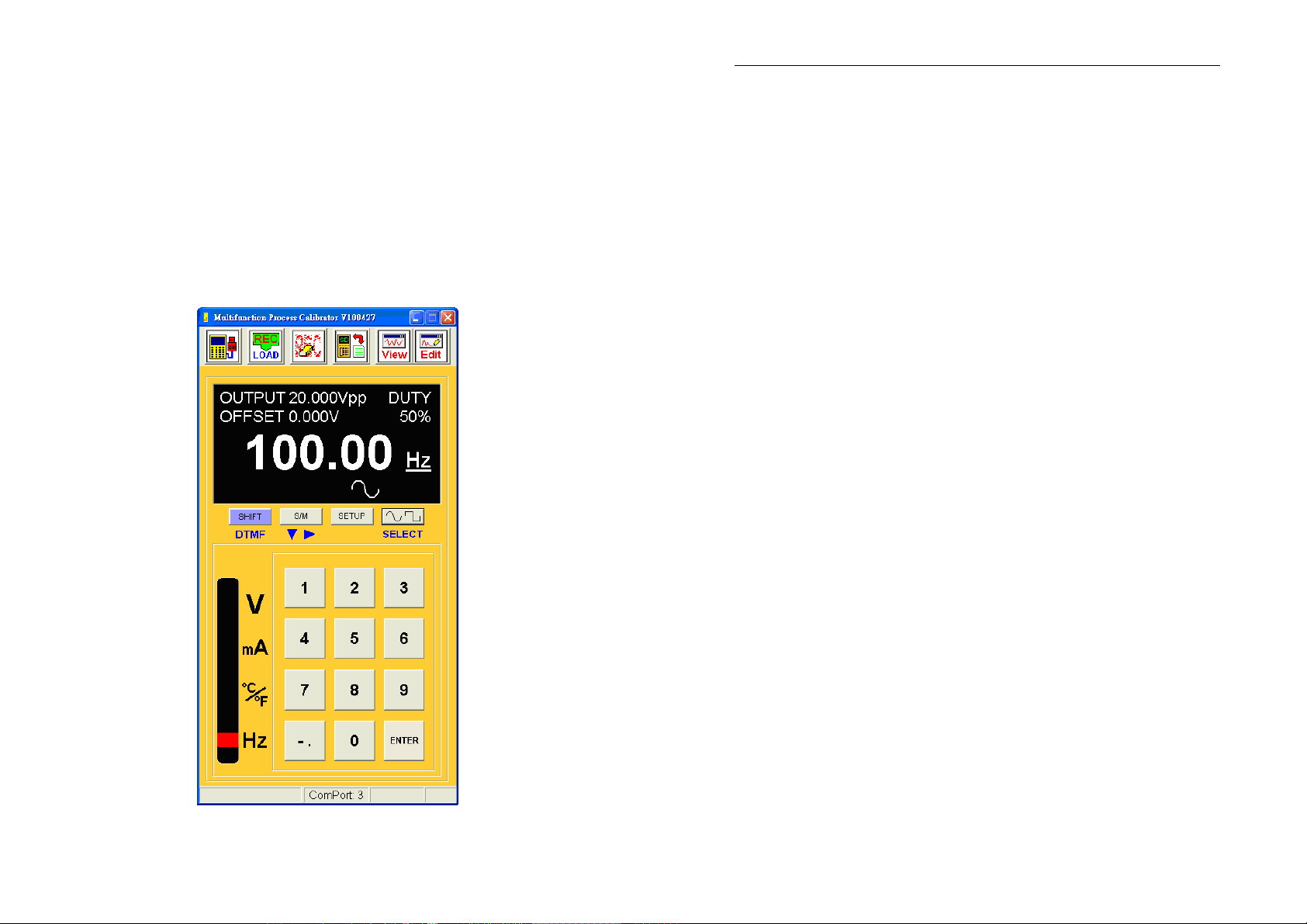
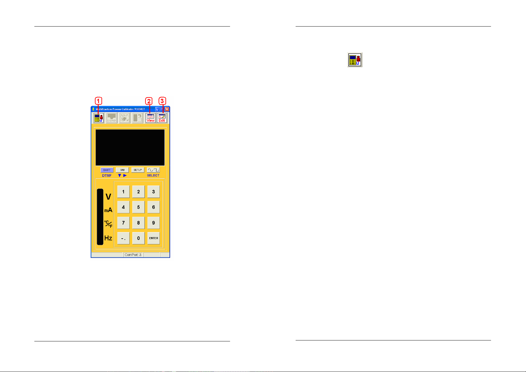
(Below is the Initial Screen of iCal software.)
3.1 Three Main Functions of iCal
1. Search and communicate with iCal
After pressing
iCal is connecting with PC. When the software can not find iCal,
there will be a message -“No ComPort”. At this moment, please
check if the USB-RS232 cable is plugged in the PC and if the
installer program is activated (please check the Device Manage r of
your system).
When the communication between PC (software) and iCal
(hardware) is successful, all the functions of tool bar will be
available. But if the communication suddenly stops, some
functions of the tool bar will not be available.
2. View Files.
, the software will search for iCal and check if
Three Main Functions of iCal software:
1. Communicate with iCal (hardware): Users can operate the
functions of iCal (hardware) via this communication.
2. View Files: providing graphics for recorded files.
3. Wave Edit: Editing user programmable waveforms.
3-1
3. Wave Edit.
3-2
Page 7
Software Operation
3.2 Main Screen
Software Operation
2. Tool Bar
There are 6 sections in the Main Screen:
1. Communication
2. Tool bar
3. LCM display
4. Remote control buttons
5. Function switch
6. Message
Download Records:
It can provide a list of records, download records and send them
into View (Files) screen. (This function will be enabled only after
users switch iCal to SETUP function.) (Under Hz function, please
try not to enter SETUP function to prevent from errors.)
When the data recorded in iCal is of the same function, they will be
automatically sent into View . But when the data recorded in iCal is
of different functions, they will be put in a list in which users can
choose the data they want to download. They will not be sent into
View, but they can be exported to EXCEL (.csv or .txt).
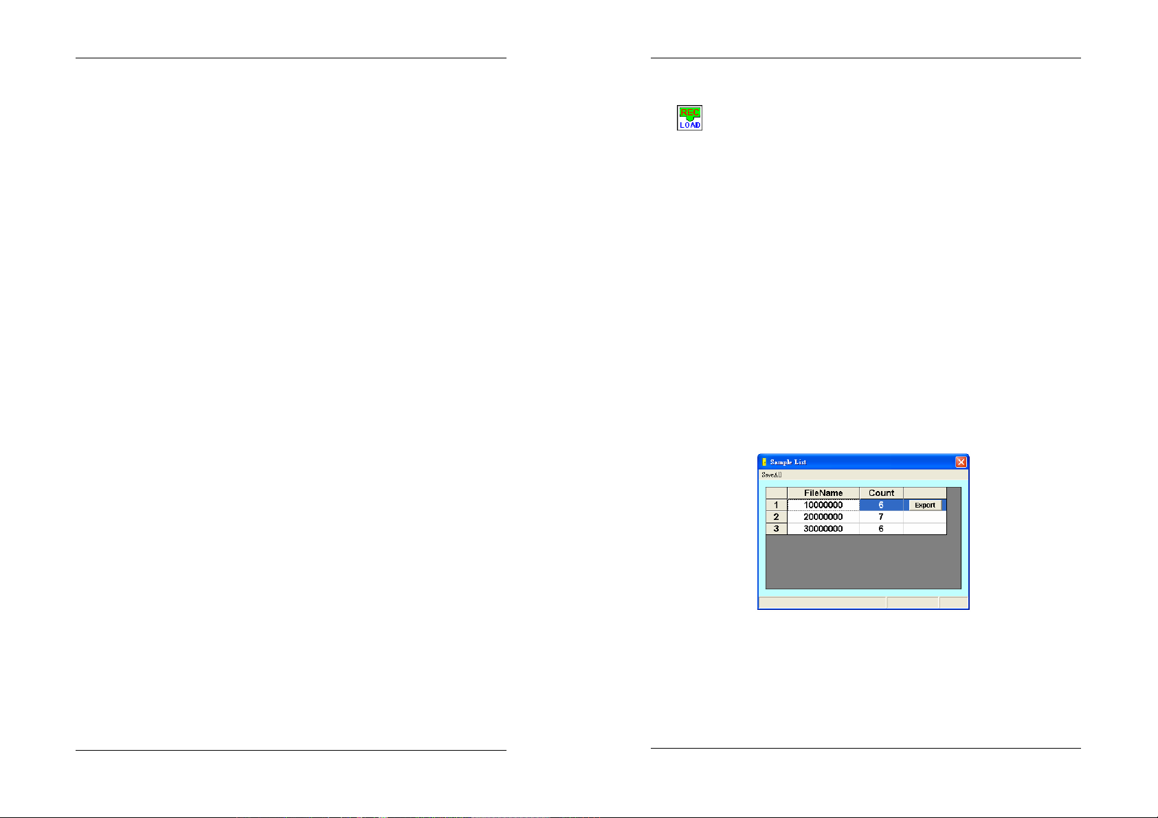
When SAMPLE is set up as “0”, there will be a sample list in which
users can choose the data they want to download.
1. Communication
To get data from iCal (hardware), first users have to m ake su re the
PC (software) has already connected with iCal. There will be a
warning message – “Error Code 8021 !!” if the communication
stops. At this moment please press this Communication button
again. If the reconnecting still doesn’t work, then please restart
the software and the iCal.
3-3
When there is a sample list (which means the files saved in iCal are
of different functions), please select the files you want to download.
Press EXPORT button to export files to EXCEL; or use the SaveAll
function to export all files to EXCEL.
3-4
Page 8
Software Operation
Software Operation
Delete Records:
It can remove all the records which are saved in iCal. (This
function will be enabled only after users switch iCal to SETUP
function.) (Under Hz function, please try not to enter SETUP
function to prevent from errors.)
Send Waveform Files
It can download and upload the user programmable wave files; and
format iCal. (This function will be enabled only after users switch
iCal to SETUP function.) (Under Hz function, please try not to
enter SETUP function to prevent from errors.) (For the file names,
please exclude ,.$%&^!@#/\().)
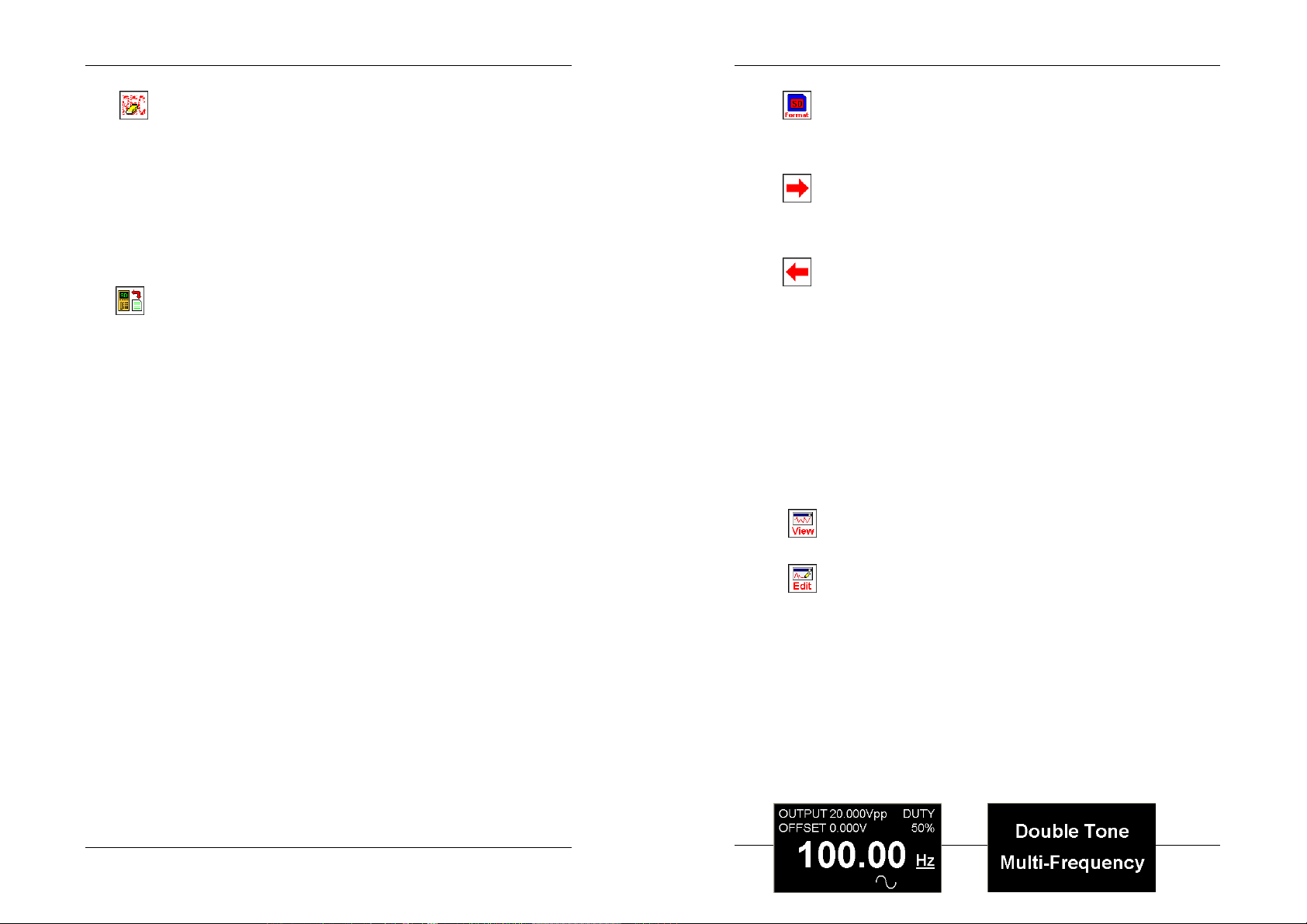
Format SD card:
Reformat the SD card inside iCal and retrieve the defaults.
Download:
Download a selected “user programmable wave” file from iCal.
Upload:
Upload a selected “user programmable wave” file to iCal.
(For the file names, please exclude ,.$%&^!@#/\().)
User can save 10 user programmable wave files in iCal.
In the SETUP function of iCal, users can set up the
programmable wave file they want to export by referring to
their file number.
Switch to View (Files) Screen.
Switch to (Wave) Edit Screen.
Under Hz function, please try not to enter SETUP function to
prevent from errors.
3. Screens of Various Functions
All the functions have their own screen display with data
except the SETUP.
3-5
3-6
Page 9
Software Operation
After pressing SHIFT, the original numeric buttons will work as
Software Operation
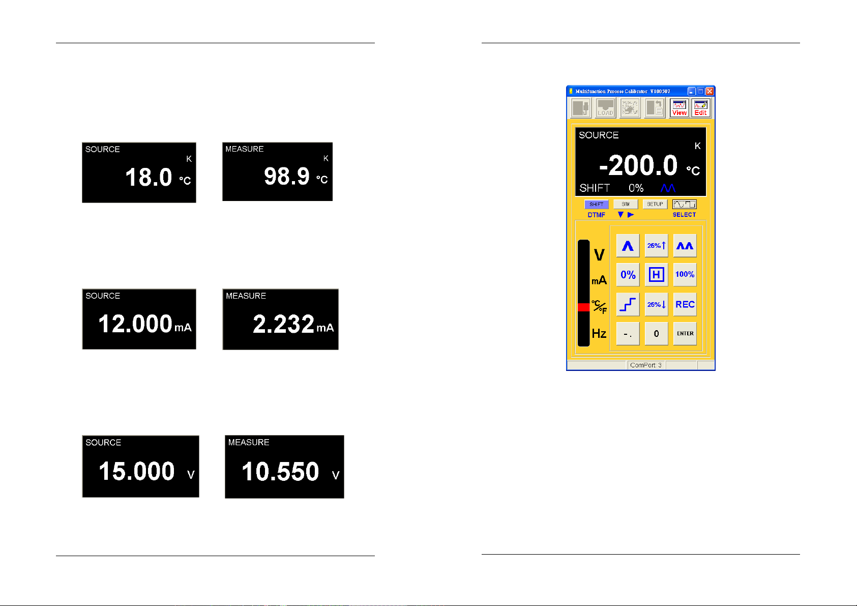
Frequency Output Function
Double Tone Multi-Frequency Function
Temperature Output Function Temperature Input Function
(In temperature input function, when ”OL” or ”-----“ is displayed which
means the current value is open circuit or overload.)
mA Output Function mA Input Function
scanning function buttons.
(When Mapping is YES, in mA input function and the value is OL, two displayed
values will be OL. Here the display is slightly different from the display of iCal.)
V Output Function V Input Function
4. Remote Control Buttons
3-7
(The screen of SHIFT scanning)
These functions are the same as the button functions of iCal
(refer to hardware manual). Here we only introduce SETUP
and S/M buttons. When entering SETUP, the software will
enter the (parameter) setup screen. When pressing S/M and
entering MEASURE, the data recording functio n of sof tware is
enabled.
SETUP of iCal
3-8
Page 10
Software Operation
the top right picture) click the left button of mouse to open
Software Operation
Here the setup is the same as the (parameter) setup of iCal.
All the parameters (of 4 functions) can be set up here and
completed by one setup.
(Under Hz function, please try not to enter SETUP function to
prevent from errors.)
the quick list for choosing special characters.
The details of parameters please refer to the operation
(hardware) manual.
Use S/M to enter MEASURE, the record function of software
is enabled.
When the function is switched to INPUT mode (like above
picture), iCal provides the following functions:
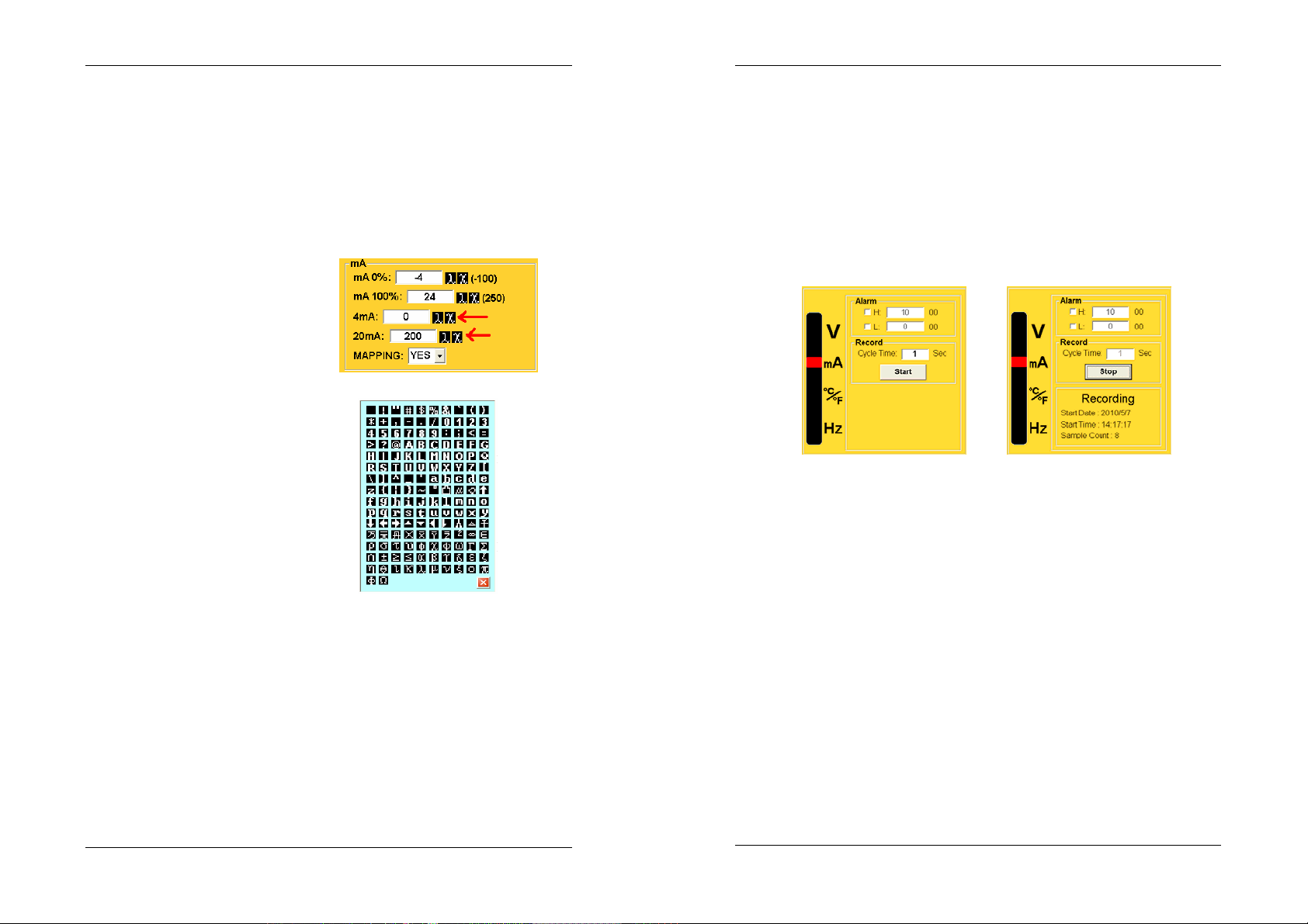
Alarm: users can set up the high/low thresholds. After
Apply: apply the current parameters to iCal.
Load: read the parameter values of iCal.
Default: retrieve the defaults (users have to press Apply).
Exit: leave the parameter setup for the previous function.
And iCal will exit the parameter setup screen as well.
Programmable Unit: (As the buttons pointed by the arrows on
3-9
ticking a H/L alarm, when value is over the thresholds, PC will
give a beep sound.
Record: After pressing Start button, the current data will be
recoded according to Cycle Time and the data will be
displayed. Pressing Stop button to stop data recording and
the data will be sent into View screen.
Note: During data recording, the function switching will stop
the recording!
3-10
Page 11
Software Operation
5. Function Switching
Software Operation
3.3 View Files
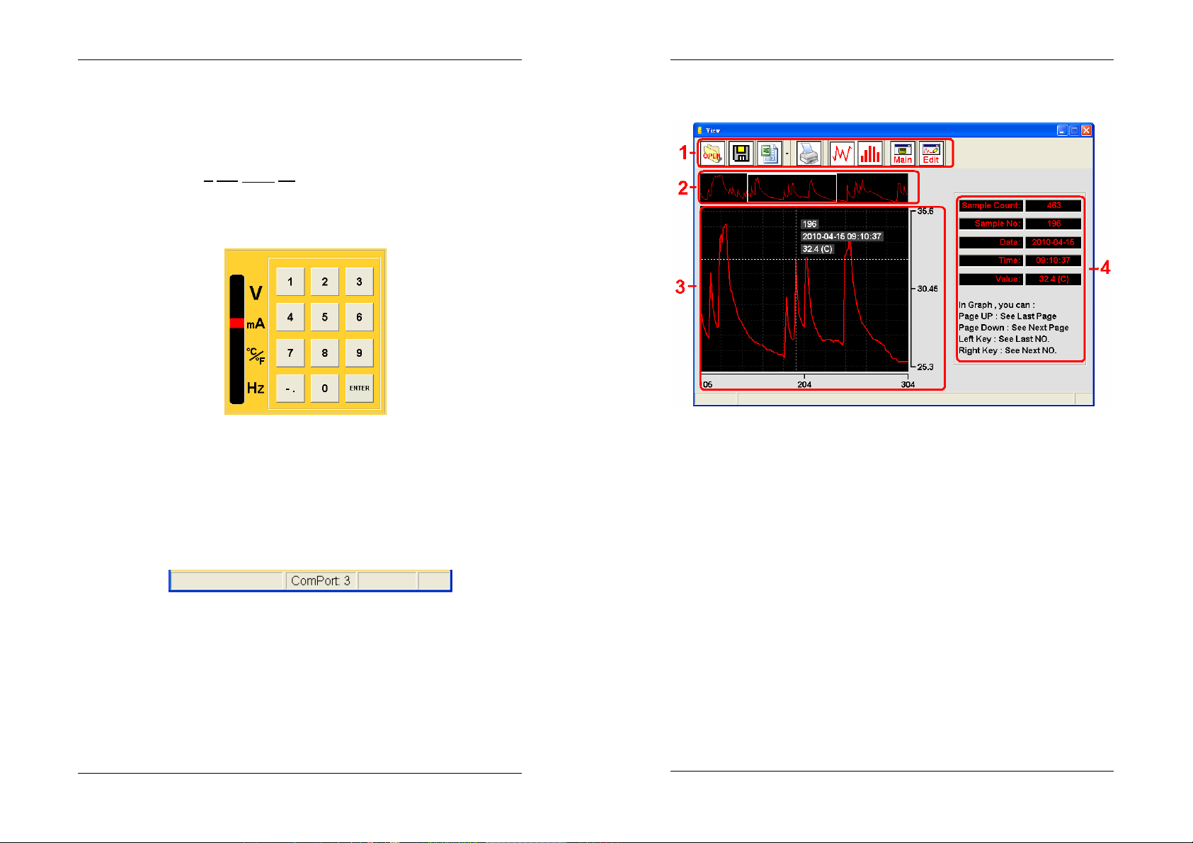
Each function has its own function display. When switching a
function, a symbol representing the current function will be
displayed ( V
(The symbol in below picture shows the function is mA.)
Here the button function of all the functions under OUTPUT
(SOURCE) mode are the same as the ones of iCal’s numeric
buttons.
mA ℃/℉ Hz)
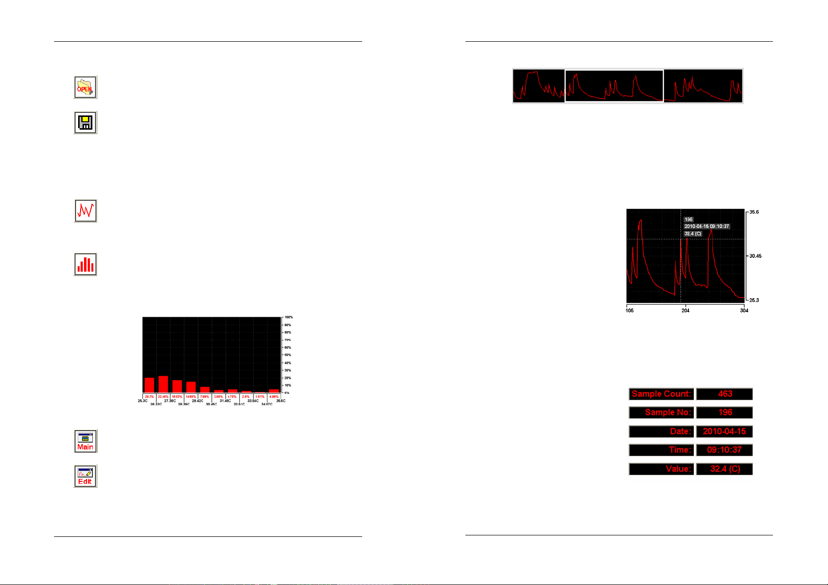
There are 4 sections in View Files screen:
1. Tool bar.
2. Data full view.
6. Message
The relating messages (about system operation) are
displayed here.
3. Curve diagram.
4. Record data figures.
3-11
3-12
Page 12
1. Tool Bar
Open files.
Software Operation
Software Operation
2. Data Full View
Save files.
Print:
Print out all the data in the current View (files) screen.
Curve display:
Display a diagram of curves.
Bar chart
All the record data (total: 100%) in the function displayed
proportionally in bars.
A full view of all the record data showed in curves.
The section of white frame represents the display function of
the Curve Data. Inside the frame, press the left button of
mouse to move the display function.
3. Curve Diagram
It displays 200 records.
Use the mouse to move
the display data, or apply
the left and right direction
buttons to move the
cursor to display data.
Users can use PageUp or PageDown buttons to view the last
or next 200 records.
4. Record Data Figures
This section shows the
Switch to Main Screen.
Switch to (Wave) Edit Screen.
3-13
figures of the cursor point
in curve diagram.
The figures of date and
time are available only for
the files saved via software.
3-14
Page 13
Software Operation
1. Tool Bar
Software Operation
3.4 Wave Edit
Edit a user programmable wave file (0.3Hz ~ 20kHz).
The total edit points is a cycle of set frequency
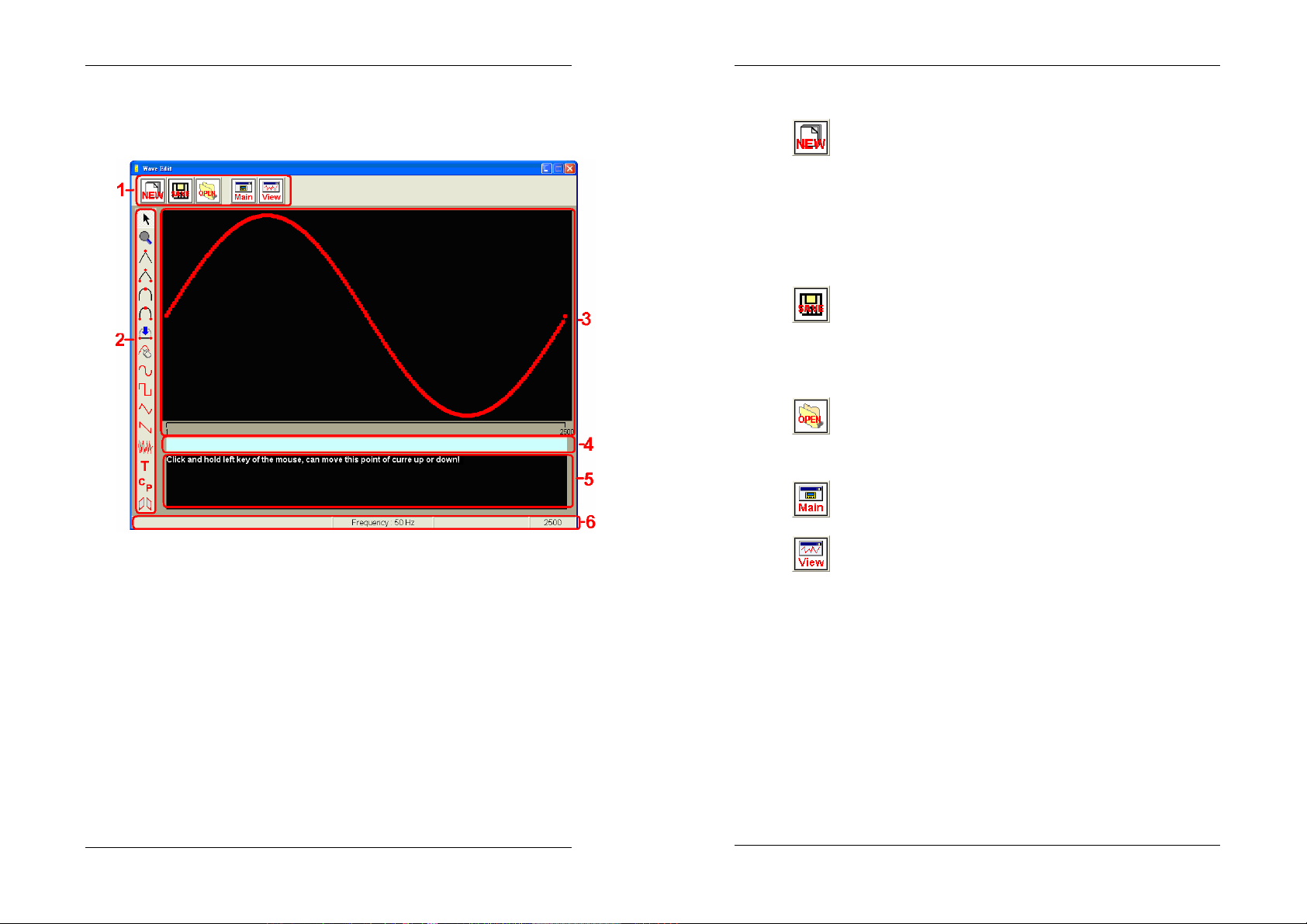
There are 6 sections in “Wave Edit” Screen:
1. Tool bar.
2. Edit tool bar.
3. Wave edit area.
4. Move display light bar.
5. Command area.
6. Message.
3-15
Create New Files:
When pressing “NEW”, users will be requested input a frequency
value.
Save Files:
When pressing “SAVE”, the waveform files of iCal will be saved.
Please exclude ,.$%&^!@#/\() for the file names.
Open Old Files:
When pressing “OPEN”, a waveform file (of iCal) will be opened.
Switch to Main Screen.
Switch to View (Files) Screen.
2. Edit Tool Bar
The tools of “Edit tool bar” will be also applied in the “Command
area” and “Wave edit area” so here the explanation can be
referred to for these 3 sections.
3-16
Page 14
Software Operation
Software Operation
Target
On the specified point (green point) of wave edit area, press the
left button of mouse and then this point will be adjusted
according to the moving (up and down) of mouse.
When using other tools, press Esc will return to the first step.
When pressing Esc on the first step will return to this tool.
Zoom in/out display
In the wave edit area,
Click the left button of mouse: zoom in (roller forward)
Click the right button of mouse: zoom out (roller backward)
For the mouse with left/right buttons and a roller, the ZOOM
function can be used without opening the zoom display. But
during the period of using some tools, the ZOOM function may
not be applied. And when using ZOOM function, the “move
display light bar” will be zoomed at the same time!
Zoom in to the extreme, the wave edit area will display 50
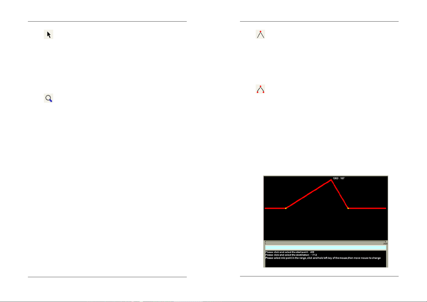
Triangular wave
On the edit point, press the left button of mouse and move it
forward and backward and then draw a 2-side-symmetry
triangular wave (the green point is the middle point).
In the Command Area, user can input alternate multiple 1~4.
Triangular wave of a selected range
Draw a triangular wave in a certain range.
The steps in the Command Area:
1. Select “start” point of the range.
2. Select “end” point of the range.
3. Choose a certain point within the range as the middle point.
Press the left button of the mouse to move this point. And
other points within the range will change positions
accordingly.
points only. Zoom out to the extreme, the wave edit area will
display complete points.
Please note the max. edit points of wave edit area is 200.
The “Message” section will show the points should be displayed
in the current wave edit area. When it shows the points are
over 200, the program will calculate proportionally and then
display the points should be displayed.
For minor adjustments, please zoom in to the extreme.
Zooming out to the extreme is for adjusting a large area.
3-17
3-18
Page 15
Software Operation
Straight Line
Software Operation
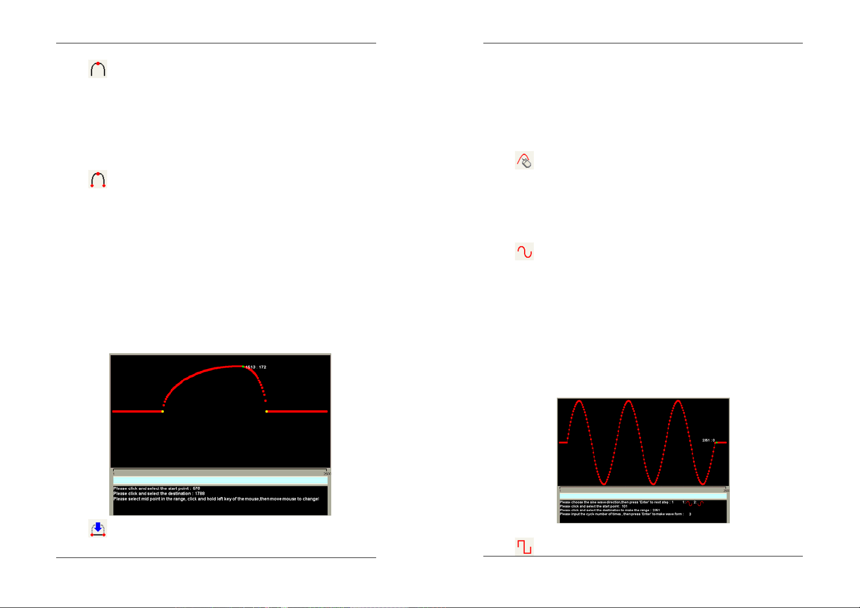
Oval Wave
On the edit point, press the left button of mouse and move it
forward and backward and then draw a 2-side-symmetry oval
wave (the green point is the middle point).
In the Command Area, user can input alternate multiple 1~3.
Oval Wave of a selected range
Draw an oval wave in a certain range.
The steps in the Command Area:
1. Select “start” point of the range.
2. Select “end” point of the range.
3. Choose a certain point within the range as the middle point.
Press the left button of the mouse to move this middle point.
When the middle point is not exactly located at the center point,
the wave created will be an arc which is not of the same circle.
Make a straight line connecting 2 points.
The steps in the Command Area:
1. Select “start” point.
2. Select “end” point.
Arbitrary
Hold ctrl button and the left button of mouse to move in the
wave edit area, the edit points will be changed according to
the mouse moving.
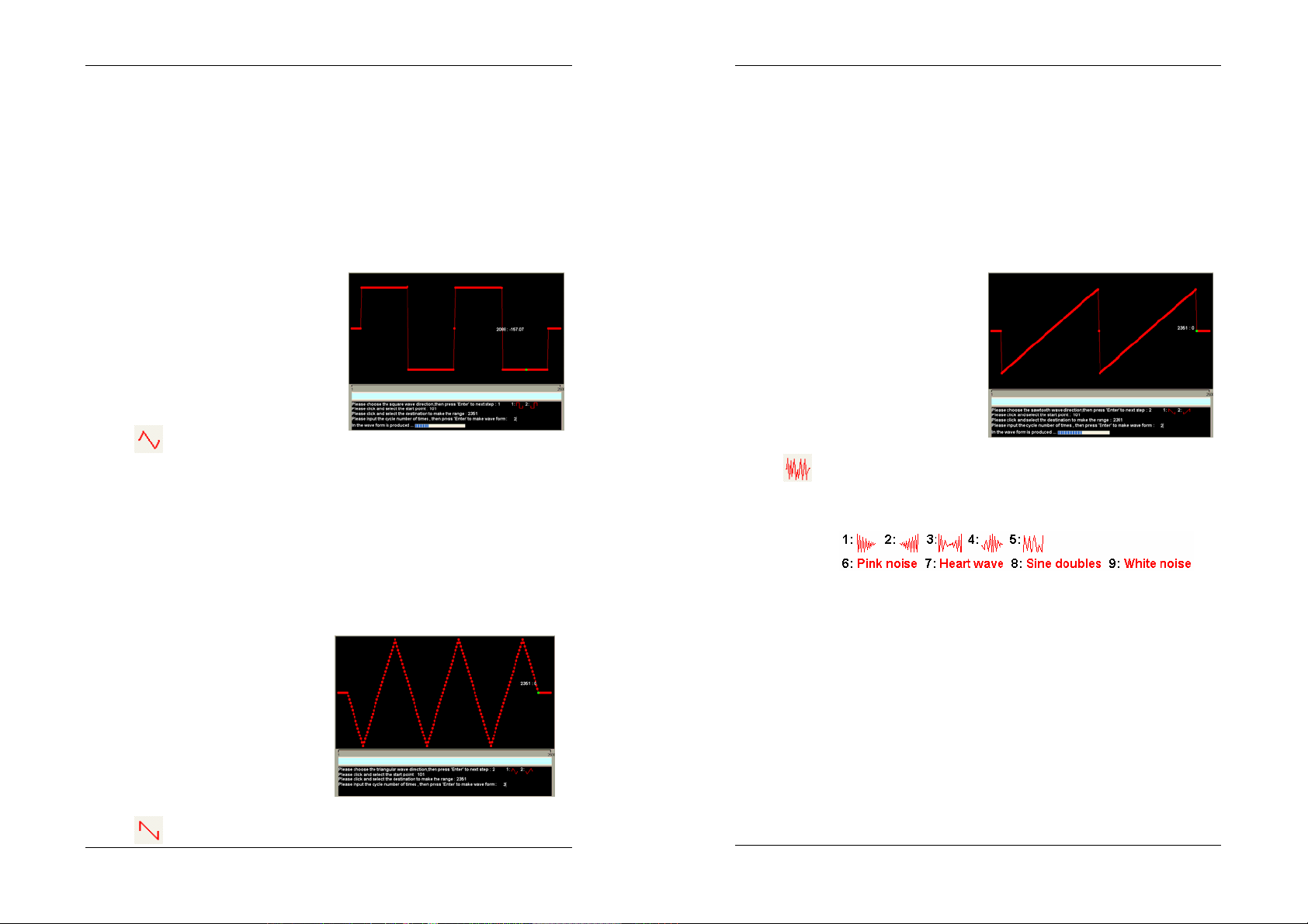
Sine Wave
Generating some sine waves in a certain range.
The steps in the Command Area:
1. Choose the sine wave direction.
2. Select “start” point of the range.
3. Select “end” point of the range.
4. Input the cycle number of times, then press “Enter” to make
wave form.
3-19
3-20
Page 16
Software Operation
Square Wave
Software Operation
Sawtooth Wave
Generating some square waves in a certain range.
The steps in the Command Area:
1. Choose the square wave direction.
2. Select “start” point of the range.
3. Select “end” point of the range.
4. Input the cycle number of times, then press “Enter” to make
wave form.
Triangular Wave
Generating some triangular waves in a certain range.
The steps in the Command Area:
1. Choose the triangular wave direction.
2. Select “start” point of the range.
3. Select “end” point of the range.
4. Input the cycle number of times, then press “Enter” to make
wave form.
Generating some truncated sine waves in a certain range.
The steps in the Command Area:
1. Choose the sawtooth wave direction.
2. Select “start” point of the range.
3. Select “end” point of the range.
4. Input the quantity of sawtooth waves, then press “Enter” to
make wave form.
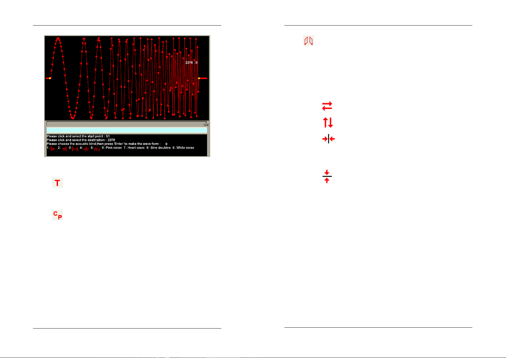
Special Wave
There are 9 special waves for users to choose:
The steps of the Command Area:
1. Select the “start” point.
2. Select the “end” point.
3. Select the type of the wave, then press “Enter” to make the
wave form.
3-21
3-22
Page 17
Software Operation
Software Operation
Mirror Shoots
This function is to mirror a selected range.
The steps of the Command Area:
1. select “start” point
2. select “end” point
3. select the type of mirror shoots, then press “Enter”.
left-right change over
top-bottom change over
On the next edit point (outside the range), post the
left-right change over. The original range is
(The above wave is “sine doubles”)
unchanged.
Text
Users can edit text for max. 110 characters.
Copy / Paste
Copy a selected range and then post it.
The steps in the Command Area:
1. Select “start” point of the range.
2. Select “end” point of the range.
3. Select “Copy” in the copy quick list.
When the selected range is copied, users can paste it on any
point in the wave edit area by clicking the right button of
mouse and opening Paste quick list. If users do not copy a
range first, then there won’t be a Paste quick list.
3. Wave Edit Area
This section provides waveform display and edit points.
The total edit points (of the wave edit area) is a cycle of set
frequency.
In the screen the max. waveform edit points is 200.
When the displayed waveform is over 200 points, the program
will calculate proportionally and display the points should be
displayed.
3-23
On the next edit point (outside the range), post the
top-bottom change over . The original range is
unchanged.
3-24
Page 18

Software Operation
For example: The current screen displays a waveform of 800
points but actually there is only 200 edit points. So the
program will calculate proportionally and display the points
should be displayed.
4. Move Display Light Bar
The function of this section is to move the display. The size of
the light bar is changed in accordance with the displayed
waveform points. When the displayed waveform points are
the complete waveform points, the light bar is the longest and
can not be moved.
5. Command Area
This section displays all the necessary steps and instructions
for wave edit.
6. Message
In this section, users can see the operation status and the
wave points of the current screen.
3-25
Page 19
WARRANTY/ DISCLAIMER
OMEGA ENGINEERING, INC. warrants this unit to be free of defects in materials and workmanship
for a period of 13 months from date of purchase. OMEGA’s WARRANTY adds an additional one (1)
month grace period to the normal one (1) year product warranty to cover handling and shipping
time. This ensures that OMEGA’s customers receive maximum coverage on each product.
If the unit malfunctions, it must be returned to the factory for evaluation. OMEGA’s Customer
Service Department will issue an Authorized Return (AR) number immediately upon phone or
written request. Upon examination by OMEGA, if the unit is found to be defective, it will be repaired
or replaced at no charge. OMEGA’s WARRANTY does not apply to defects resulting from any action
of the purchaser, including but not limited to mishandling, improper interfacing, operation outside
of design limits, improper repair, or unauthorized modification. This WARRANTY is VOID if the unit
shows evidence of having been tampered with or shows evidence of having been damaged as a
result of excessive corrosion; or current, heat, moisture or vibration; improper specification;
misapplication; misuse or other operating conditions outside of OMEGA’s control. Components in
which wear is not warranted, include but are not limited to contact points, fuses, and triacs.
OMEGA is pleased to offer suggestions on the use of its various products. However,
OMEGA neither assumes responsibility for any omissions or errors nor assumes liability
for any damages that result from the use of its products in accordance with
information provided by OMEGA, either verbal or written. OMEGA warrants only that
the parts manufactured by the company will be as specified and free of defects.
OMEGA MAKES NO OTHER WARRANTIES OR REPRESENTATIONS OF ANY KIND
WHATSOEVER, EXPRESSED OR IMPLIED, EXCEPT THAT OF TITLE, AND ALL IMPLIED
WARRANTIES INCLUDING ANY WARRANTY OF MERCHANTABILITY AND FITNESS FOR
A PARTICULAR PURPOSE ARE HEREBY DISCLAIMED. LIMITATION OF LIABILITY: The
remedies of purchaser set forth herein are exclusive, and the total liability of OMEGA
with respect to this order, whether based on c ontract, warranty, negligence,
indemnification, strict liability or otherwise, shall not exceed the purchase price of the
component upon which liability is based. In no event shall OMEGA be liable for
consequential, incidental or special damages.
CONDITIONS: Equipment sold by OMEGA is not intended to be used, nor shall it be used: (1) as a
“Basic Component” under 10 CFR 21 (NRC), used in or with any nuclear installation or activity; or
(2) in medical applications or used on humans. Should any Product(s) be used in or with any
nuclear installation or activity, medical
OMEGA assumes no responsibility as set forth in our basic WARRANTY / DISCLAIMER language,
additionally, purchaser will indemnify OMEGA and hold OMEGA harmless from any liability
and,
or damage whatsoever arising out of the use of the Product(s) in such a manner.
application, used on humans, or misused in any way,
Where Do I Find Everything I Need for
Process Measurement and Control?
OMEGA…Of Course!
Shop online at omega.com
TEMPERATURE
Thermocouple, RTD & Thermistor Probes, Connectors, Panels & Assemblies
Wire: Thermocouple, RTD & Thermistor
Calibrators & Ice Point References
Recorders, Controllers & Process Monitors
Infrared Pyrometers
PRESSURE, STRAIN AND FORCE
Transducers & Strain Gages
Load Cells & Pressure Gages
Displacement Transducers
Instrumentation & Accessories
FLOW/LEVEL
Rotameters, Gas Mass Flowmeters & Flow Computers
Air Velocity Indicators
Turbine/Paddlewheel Systems
Totalizers & Batch Controllers
pH/CONDUCTIVITY
pH Electrodes, Testers & Accessories
Benchtop/Laboratory Meters
Controllers, Calibrators, Simulators & Pumps
Industrial pH & Conductivity Equipment
SM
Direct all warranty and repair requests/inquiries to the OMEGA Customer Service Department.
RETURN REQUESTS/INQUIRIES
BEFORE RETURNING ANY PRODUCT(S) TO OMEGA, PURCHASER MUST OBTAIN AN
AUTHORIZED RETURN (AR) NUMBER FROM OMEGA’S CUSTOMER SERVICE DEPARTMENT (IN
ORDER TO AVOID PROCESSING DELAYS). The assigned AR number should then be marked on the
outside of the return package and on any correspondence.
The purchaser is responsible for shipping charges, freight, insurance and proper packaging to
prevent breakage in transit.
FOR WARRANTY
following information available BEFORE
contacting OMEGA:
1. Purchase Order number under which
the product was PURCHASED,
2. Model and serial number of the product
under warranty, and
3. Repair instructions and/or specific
problems relative to the product.
OMEGA’s policy is to make running changes, not model changes, whenever an improvement is possible.
This affords our customers the latest in technology and engineering.
OMEGA is a registered trademark of OMEGA ENGINEERING, INC.
© Copyright 2012 OMEGA ENGINEERING, INC. All rights reserved. This document may not be copied, photocopied, repro-
duced, translated, or reduced to any electronic medium or machine-readable form, in whole or in part, without the prior
written consent of OMEGA ENGINEERING, INC.
RETURNS, please have the
FOR NON-WARRANTY REPAIRS,
for current repair charges. Have the following
information available BEFORE contacting OMEGA:
1. Purchase Order number to cover the
COST of the repair,
2. Model and serial number of the
product, and
3. Repair instructions and/or specific problems
relative to the product.
consult OMEGA
DATA ACQUISITION
Data Acquisition & Engineering Software
Communications-Based Acquisition Systems
Plug-in Cards for Apple, IBM & Compatibles
Data Logging Systems
Recorders, Printers & Plotters
HEATERS
Heating Cable
Cartridge & Strip Heaters
Immersion & Band Heaters
Flexible Heaters
Laboratory Heaters
ENVIRONMENTAL
MONITORING AND CONTROL
Metering & Control Instrumentation
Refractometers
Pumps & Tubing
Air, Soil & Water Monitors
Industrial Water & Wastewater Treatment
pH, Conductivity & Dissolved Oxygen Instruments
M5161/0712
 Loading...