

Page 1
CL3512ACL3512A
CL3512A
CL3512ACL3512A
Digital Thermometer & CalibratorDigital Thermometer & Calibrator
Digital Thermometer & Calibrator
Digital Thermometer & CalibratorDigital Thermometer & Calibrator
Page 2

omega.com
OMEGAnetSM On-Line Service
http://www.omega.com
USA: ISO 9001 Certified Canada:
One Omega Drive, Box 4047 976 Bergar
Stamford, CT 06907-0047 Laval (Quebec) H7L5A1
Tel: (203) 359-1660 Tel: (514) 856-6928
FAX: (203)359-7700 FAX: (514) 856-6886
e-mail: info@omega.com e-mail: info@omega.com
USA and Canada: Mexico and Latin America:
Sales Service: 1-800-826-6342 / 1-800-TC-OMEGA
Customer Service: 1-800-622-2378 / 1-800-622-BEST
Engineering Service: 1-800-872-9436 / 1-800-USA-WHENSMEn Español: (203) 359-7803
TELEX: 996404 EASYLINK: 62968934 CABLE: OMEGA e-mail: espanol@omega.com
Benelux: Germany/Austria:
Postbus 8034, 1180 LA Amstelveen, Daimlerstrasse 26, D-75392
The Netherlands Deckenpfronn, Germany
Tel: (31) 20 6418405 FAX: (31) 20 6434643 Tel: 49 (07056) 3017 FAX: 49 (07056) 8540
Toll Free in Benelux: 06 0993344 Toll Free in Germany: 0800 82 66342
e-mail: nl@omega.com e-mail: germany@omega.com
Czech Republic: United Kingdom: ISO 9002 Certified
ul. Rude armady 1868, 733 01 Karvina- One Omega Drive
Hranice, Czech Repubic Riverbend Technology Centre Northbank, Irlam,
Tel: 420 (69) 6311627 FAX: 420 (69) 6311114 Manchester, M44 5EX, England
e-mail: czech@omega.com Tel: 44 (161) 777-6611 FAX: 44 (161) 777-6622
France:
9, rue Denis Papin, 78190 Trappes Toll Free in England: 0800-488-488
Tel: (33) 130-621-400 FAX: (33)130-699-120 e-mail: sales@omega.com.uk
Toll Free in France: 0800-4-06342
e-mail: france@omega.com
It is the policy of OMEGA to comply with all worldwide safety and EMC/EMI regulations that apply. OMEGA is constantly pursuing certification
of its products to the European New Approach Directives. OMEGA will add the CE mark to every appropriate device upon certification.
The information contained in this document is believed to be correct but OMEGA Engineering, Inc. accepts no liability for any errors it contains,
and reserves the right to alter specifications without notice.
WARNING: These products are not designed for use in, and should not be used for, patient connected application.
For immediate technical or application assistance:
Servicing North America:
SM
SM
Servicing Europe:
TM
Internet e-mail
info@omega.com
Tel: (95) 800-TC-OMEGA
FAX: (95) 203-359-7807
SM
Page 3

Table of contents
1.0 Introduction
1.1 Safety Information
1.2 Unpacking
2.0 Operation Procedure
2.1 Unit Drawing
2.2 Description of Buttons and Switches
2.3 Read Mode Procedure
2.4 Source Mode Procedure
3.0 Operator Maintenance
4.0 Specifications
5.0 Calibration Procedure
Page 4

1.0 Introduction
The OMEGA® CL3512A calibrator/thermometer is two meters in one. The
CL3512A simulates type J/K/T/E thermocouple signals. Each signal is adjustable
by using the coarse and fine dials. The CL3512A can also be used as a dual
type J/K/T/E thermocouple input thermometer. Features include a large 3½
digit display with backlighting and display selections of HOLD, °C/°F, and
0.1/1°.
The source mode of the CL3512A simulates the thermocouple output to check
the operation of a thermocouple meter and make rough calibration adjustments.
A more accurate calibrator would be required for calibration of thermocouple
meters to specify tolerances.
1.1 Safety Information
It is recommended that you read the safety and operation instructions before
using the thermometer.
WARNING
To avoid electrical shock, do not use this instrument when working
voltages at the measurement surface over 24V AC or DC.
To avoid damage or burns, do not make temperature measurement
Repeated sharp flexing can break the thermocouple leads. To prolong
lead life, avoid sharp bends in the leads, especially near the connector.
WARNING
in microwave ovens.
CAUTION
1
Page 5

1.2 Unpacking
Remove the packing list and verify that all equipment has been received. If
there are any questions about the shipment, please call the OMEGA Customer
Service Department.
Upon receipt of shipment, inspect the container and equipment for any signs
of damage. Immediately report any damage to the shipping agent.
NOTE
The carrier will not honor any claims unless all shipping
material is saved for their examination. After examining and
removing contents, save the packing material and carton in the
event reshipment is necessary.
The following is supplied in the box:
• CL3512A
• Rubber boot
• 2 K beaded wire thermocouples
• K calibration cable
• 9 volt battery
• Operator's manual
2
Page 6
2.0 Operation Proceedure
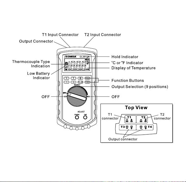
2.1 Drawing of Unit
Actual Dimensions: 195mm(H) x 92mm(W) x 53mm(D)
3
Page 7

2.2 Descriptions of Buttons and Switches
/ Buttons
Temperature is displayed in either degrees Celsius(°C) or degrees
Fahrenheit(°F). When the thermometer is turned on, it is set to the temperature
scale that was in use when the thermometer was last turned off. To change the
temperature scale, press the °C or °F key.
Button
Press " " button to toggle the on and off backlight. The backlight will switchoff automatically after 30 seconds.
Button (HOLD Mode)
Press the HOLD key to enter the Data Hold mode, the "HOLD" annunciator is
displayed. When HOLD mode is selected, the thermometer will hold the
present reading and stop all further measurements.
Pressing the HOLD key again will cancel HOLD mode causing the thermometer
to resume taking measurements.
Button (K/J/T/E Input Thermocouple Type Selection)
The TYPE key allows for selection of J, K, E or T thermocouple types as either
the input or simulated output. To select thermocouple type press type key
once. Unit will briefly show 1888 and beep and then the type of thermocouple
selected will be indicated on the left hand side of the display. Continue pressing
the type key to step through the thermocouple types until desired type is
indicated.
4
Page 8

/ / Input Selections
The input selection indicates which input is selected; T1 thermocouple, T2
thermocouple or the difference between the two thermocouples (T1-T2).When
the thermometer is turned on, it is set to the temperature input that was in use
when the thermometer was last turned off.
Selector Switch
The circular selector switch is used to turn the unit off (!) or to select Reading
Mode (Input) or Simulation Mode (Output). There are nine selector switch
positions under output which provide rough adjustment of the simulated output.
Adjust
Course and fine adjustment Dials are used in Simulation Mode to allow a particular
simulated temperature to be selected once the output has been adjusted close to
the desired temperature using the selector switch.
5
Page 9

2.3 Read Mode Proceedure
1. Plug Thermocouple Sensor into input T1 and/or T2.
2. Turn selector switch to Input.
3. Select proper thermocouple type (J, K, T or E) using type button.
4. Press T1 button to read thermocouple connected to input T1.
Press T2 button to read thermocouple connected to input T2.
Press T1-T2 if difference between T1 and T2 is to be read.
5. To Hold reading press HOLD button. To resume making measurements
press HOLD again.
Note: Unit will display -OL if input is out of range or thermocouple is
broken or not connected to proper input.
To save battery life, CL3512A will turn off automatically if no is key is
pressed for 70 minutes.
6
Page 10

2.4 Source Mode Procedure (Calibration Simulation)
1. Turn CL3512A on by turning selector switch to any one of the output
selector positions.
2. Press T1 button.
3. Select thermocouple type (J, K, T or E) using type button.
Select °C or °F using °C or °F buttons.
4. Plug proper type of thermocouple wire into either one of the two output
connectors. (SMP male connector required)
5. Attach the other end of the thermocouple wire to the instrument being
tested/calibrated.
6. Move the output range switch to the temperature value close to the
desired simulated value.
Note: There are 9 temperature range switch positions arranged from left
to right representing low to high temperatures.
The display will read -OL if the output voltage for the meter is
higher than the maximum voltage for that particular thermocouple
type. For type T this will be in the highest 4 positions, type K in
the highest 3 positions, type J in the highest 2 positions, and type
E in the highest position only.
7. Adjust course and/or fine adjustment dial until desired temperature is
displayed on CL3512A.
8. Instrument under test should read same temperature as CL3512A. If not
adjust instrument under test or have recalibrated.
9. Repeat steps 6-8 at different temperatures as needed.
7
Page 11
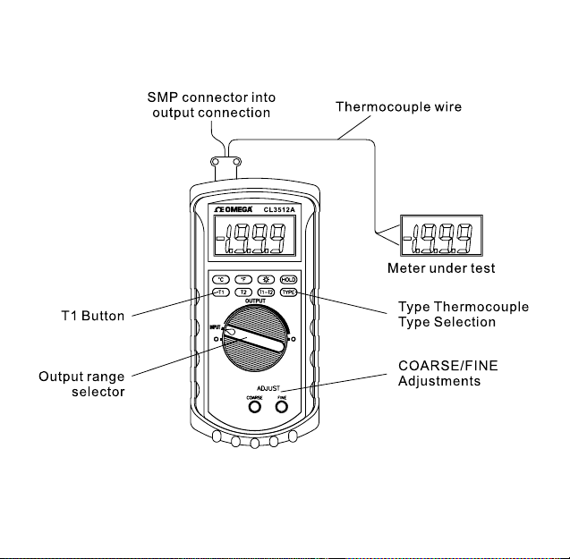
Source Mode Diagram
8
Page 12

3.0 Operator
To avoid possible electrical shock, disconnect the thermocouple
connectors from the thermometer before removing the cover.
Battery Replacement
Power is supplied by a 9 volt "transistor" battery. The " " appears on the LCD
display when replacement is needed. To replace the battery, remove the two
screws from the back of the meter and lift off the battery cover. Remove the
battery from battery contacts.
Maintenance
WARNING
9
Page 13

4.0 Specifications
ELECTRICAL
Temperature Scale: Celsius or Fahrenheit user-selectable
Measurement Range:
Thermocouple Range
K-TYPE(0.1°C) -200°C to 1372°C , -328°F to 1999°F
J-TYPE(0.1°C) -210°C to 1200°C , -346°F to 1999°F
T-TYPE(0.1°C) -200°C to 400°C , -328°F to 752°F
E-TYPE(0.1°C) -220°C to 1000°C , -364°F to 1832°F
Calibration Range:
-210°C to 1372°C, (-364°F to 1999°F)
Auto range: 0.1°C/1°C , 0.1°F/1°F
Accuracy: Accuracy is specified for operating temperatures over the range
of 18°C to 28°C (64°F to 82°F), for 1 year, not including thermocouple
error. (Read mode)
±(0.1%rdg + 1°C) range -60°C to 1372°C
±(0.1%rdg + 2°C) range -60°C to -220°C
±(0.1%rdg + 2°F) range -76°F to 1999°F
±(0.1%rdg + 4°F) range -76°F to -364°F
Simulation Accuracy: Measurement accuracy plus 1°C
ENVIRONMENTAL
Ambient Operating Ranges: 0°C to 50°C (32°F to 122°F) <80% R.H.
Storage Temperature: -20°C to 60°C (-4°F to 140°F) <70% R.H.
10
Page 14

GENERAL
Display: 3½ digit liquid crystal display (LCD) with a maximum reading of
1999.
Polarity: Automatic,positive implied,negative polarity indication.
Overrange: -OL is displayed.
Zero: Automatic.
Low battery indication: the"
drops below the operating level.
Measurement rate: 1 times/second.
Accuracy: Stated accuracy at 23°C±5°C,<75% relative humidity.
Dimensions: 195mm(H) x 92mm(W) x 53mm(D).
Weight: approx. 9 oz. (250g) including battery.
Input Connector: Accepts standard miniature thermocouple connectors (flat
blades spaced 7.9mm, center to center SMP type).
Battery Life: 100 hours typical with carbon zinc battery
Auto power off: The meter key switch inactive for more than 70 minutes.
Temperature Coefficient: 0.1 times the applicable accuracy specification
per °C from 0°C to 18°C and 28°C to 50°C (32°F to 64°F and 82°F to 122°F).
Input Protection: 24V dc or 24V ac rms maximum input voltage on any
combination of input pins.
Maximum Differential Common Mode Voltage (Maximum Voltage between
T1 and T2 during measurement): 1volt.
"is displayed when the battery voltage
11
Page 15

5.0 CL3152A Calibration Procedure
Note: The following calibration procedure should be performed only by
qualified technicians who have access to the items as following
items:
Equipment: 1) A very accurate millivolt source.
2) A TRC III ICE Point Reference or ice bath with type
K thermocouple.
Input Funtion "Calibration"
1. Before turning on the meter, turn the RANGE knob to position "INPUT"
and then move the jumper to the upper two pins of J5 which is at the left
upper of the PCB.
2. Input DCV 25.60mV to the T1. After the display is stabilized, then press
key and "0.1" is displayed.
3. Input DCV 74.00mV. After the display has stabilized, then press
key and "OL" is displayed.
4. Input
5. Do Not press any key. The meter will turn off automatically after 10
6. Turn the meter back on then input
0°C (K-type, use a K thermocouple on an ice bath, or
thermocouple calibrator).
After the display has stabilized then press
key.
seconds. Move
calibrated if the display reading reads 0°C.
the jumper
to the lower two pins of J5.
0°C (K-type). The meter will be
12
Page 16

"Simulated Output" Test
1. Turn the knob "COARSE" right to the end, knob of RANGE turn right to
the last two position, press "TYPE" key to select "TYPE-E", if display
does not show "OL" then adjust VR4 slowly to make display ="OL"
(Note: Take care not to adjust VR4 too far).
13
Page 17

CL3512A CALIBRATION PROCEDURES
Note: The following calibration procedure should perform only by qualified technicians
who have access to the items as following.
Equipment: The class of calibrator had better 10 times greater than the measured meter.
INPUT FUNTION CALIBRATE
1. Before turn on the meter, turn the RANGE knob to position "INPUT" and then
move short pin to upper two pin of J5 which is at the left upper of PCB.
2. Input DCV 25.6m V to the T1.After the display is stabilized,then press “ “
key and "0.1" is displayed.
3. Input DCV 74mV then press “ “ key. After the display is stabilized, then
press “ “ key and "OL" is displayed.
4. Input 0°C (K-type). After the display is stabilized and then press “ “ key.
5. Don't push any key and the meter will turn off automatically after 10 seconds.
Move short pin to lower two pin of J5.
6. Turn on the meter then input 0°C (K-type). The display reading reads 0°C if
the calibration procedure is right.
“CALIBRATION FUNTION” CALIBRATE
1.Turn the knob "COARSE" right to the end, knob of RANGE turn right to the last
two position, press "TYPE" key to select "TYPE-E", if display does not show "OL",
then adjust VR4 slowly to make display ="OL" (if “OL” displayed don’t adjust VR4
too far).
1
Page 18

OMEGA ENGINEERING, INC. warrants this unit to be free of defects in materials and workmanship for a period of 13 months
from date of purchase. OMEGA Warranty adds an additional one (1) month grace period to the normal one (1) year product
warranty to cover handling and shipping time. This ensures that OMEGA's customers receive maxim um cov erage on each product.If
the unit should malfunction, it must be returned to the factory for evaluation. OMEGA's Customer Service Department will issue an
Authorized Return (AR) number immediately upon phone or written request. Upon examination by OMEGA, if the unit is found to
be defective it will be repaired or replaced at no charge. OMEGA's WARRANTY does not apply to def ects resulting from any action
of the purchaser, including but not limited to mishandling, improper interfacing, operation outside of design limits, improper repair,
or unauthorized modification. This W ARRANTY is V OID if the unit shows evidence of having been tampered with or sho ws evidence
of being damaged as a result of excessive corrosion; or current, heat moisture or vibr ation; improper specification; misapplication;
misuse or other operating conditions outside of OMEGA's control. Components which wear are not warranted, including but not
limited to contact points, fuses, and triacs.
OMEGA is pleased to offer suggestions on the use of its various products. H owever , OMEGA neither assumes responsibility
for any omissions or errors nor assumes liability for an y damages that result from the use of its products in accordance
with information provided by OMEGA, either verbal or written. OMEGA warrants only that the parts manufactured by it
will be as specified and free of defects. OMEGA MAKES NO OTHER WARRANTIES OR REPRESENTATIONS OF ANY KIND
WHATSOEVER, EXPRESSED OR IMPLIED, EXCEPT THAT OF TITLE AND ALL IMPLIED WARRANTIES INCLUDING ANY
WARRANTY OF MERCHANTABILITY AND FITNESS FOR A PARTICULAR PURPOSE ARE HEREBY DISCLAIMED.
LIMITATION OF LIABILITY: The remedies of purc haser set forth herein are exc lusive and the total liability of OMEGA with
respect to this order, whether based on contract, warranty, negligence, indemnification, strict liability or otherwise, shall
not exceed the purchase price of the component upon which liability is based. In no event shall OMEGA be liable for
consequential, incidental or special damages.
CONDITIONS: Equipment sold by OMEGA is not intended to be used, nor shall it be used: (1) as a "Basic Component" under 10
CFR 21 (NRC), used in or with any nuclear installation or activity; or (2) in medical applications or used on humans. Should any
Product(s) be used in or with any nuclear installation or activity, medical application, used on humans, or misused in any way,
OMEGA assumes no responsibility as set forth in our basic WARRANTY / DISCLAIMER language, and additionally, purchaser will
indemnify OMEGA and hold OMEGA harmless from any liability or damage whatsoever arising out of the use of the Product(s) in
such a manner.
Direct all warranty and repair requests/inquiries to the OMEGA Customer Service Department. BEFORE RETURNING ANY
PRODUCT(S) TO OMEGA, PURCHASER MUST OBTAIN AN AUTHORIZED RETURN (AR) NUMBER FROM OMEGA'S
CUSTOMER SERVICE DEPARTMENT (IN ORDER TO AVOID PROCESSING DELAYS). The assigned AR number should then
be marked on the outside of the return package and on any correspondence.
The purchaser is responsible for shipping charges, freight, insurance and proper packaging to prevent breakage in transit.
FOR WARRANTY RETURNS, please ha ve the following
information available BEFORE contacting OMEGA:
1. P.O. number under which the product was PURCHASED.
2. Model and serial number of the product under warranty, and
3. Repair instructions and/or specific problems relative to the
product.
OMEGA's policy is to make running changes, not model changes, whenever an improvement is possible. This affords our customers the latest
in technology and engineering. OMEGA is a registered trademark of OMEGA ENGINEERING, INC. © Copyright 2002 OMEGA ENGINEERING,
INC. All rights reserved. This document may not be copied, photocopied, reproduced, translated, or reduced to any electronic medium or
machine-readable from, in whole or in part, without prior written consent of OMEGA ENGINEERING, INC.
WARRANTY / DISCLAIMER
RETURN REQUESTS / INQUIRIES
FOR NON-WARRANTY REPAIRS, consult OMEGA for
current repair charges. Have the following information
available BEFORE contacting OMEGA:
1. P.O. number to cover the COST of the repair.
2. Model and serial number of product , and
3. Repair instructions and/or specific problems relative to the
product.
Page 19

Where Do I Find Everything I Need for
Process Measurement and Control?
OMEGA...Of Course!
TEMPERATURE
" Thermocouple, RTD & Thermistor
Probes, Connectors, Panels & Assemblies
" Wire: Thermocouple, RTD & Thermistor
" Calibrators & Ice Point References
" Recorders, Controllers & Process Monitors
" Infrared Pyrometers
PRESSURE/STRAIN AND FORCE
" Transducers & Strain Gauges
" Load Cells & Pressure Gauges
" Displacement Transducers
" Instrumentation & Accessories
FLOW/LEVEL
" Rotameters, Gas Mass Flowmeters
& Flow Computers
" Air Velocity Indicators
" Turbine/Paddlewheel Systems
" Totalizers & Batch Controllers
pH/CONDUCTIVITY
" pH Electrodes, Testers & Accessories
" Benchtop/Laboratory Meters
" Controllers, Calibrators, Simulators
& Pumps
" Industrial pH & Conductivity Equipment
M-3806/0502
DATA ACQUISITION
" Data Acquisition &
Engineering Software
" Communications-Based
Acquisition Systems
" Plug-in Cards for Apple, IBM
& Compatibles
" Datalogging Systems
" Recorders, Printers & Plotters
HEATERS
" Heating Cable
" Cartridge & Strip Heaters
" Immersion & Band Heaters
" Flexible Heaters
" Laboratory Heaters
ENVIRONMENTAL
MONITORING AND CONTROL
" Metering & Control Instrumentation
" Refractometers
" Pumps & Tubing
" Air, Soil & Water Monitors
" Industrial Water & Wastewater
Treatment
" pH, Conductivity & Dissolved Oxygen
Instruments
 Loading...