

Page 1
omega.com
e-mail: [email protected]
For latest product manuals:
omegamanual.info
User’s Guide
CL309A-PLUS
Automated Diagnostic
4-20 mA Calibrator
®
MADE IN
Shop online at
Page 2

Servicing North America:
U.S.A.: Omega Engineering, Inc., One Omega Drive, P.O. Box 4047
ISO 9001 Certified
Stamford, CT 06907-0047
Toll-Free: 1-800-826-6342 Tel: (203) 359-1660
FAX: (203) 359-7700 e-mail: [email protected]
Canada: 976 Bergar
Laval (Quebec), H7L 5A1 Canada
Toll-Free: 1-800-826-6342 TEL: (514) 856-6928
FAX: (514) 856-6886 e-mail: [email protected]
For immediate technical or application assistance:
U.S.A. and Canada: Sales Service: 1-800-826-6342/1-800-TC-OMEGA
®
Customer Service: 1-800-622-2378/1-800-622-BEST
®
Engineering Service: 1-800-872-9436/1-800-USA-WHEN
®
Mexico En Español: 001 (203) 359-7803 FAX: 001 (203) 359-7807
Latin America [email protected] e-mail: [email protected]
Servicing Europe:
Benelux: Managed by the United Kingdom Office
Czech Republic: Frystatska 184
733 01 Karviná, Czech Republic
Toll-Free: 0800-1-66342 TEL: +420-59-6311899
FAX: +420-59-6311114 e-mail: [email protected]
France: Managed by the United Kingdom Office
Toll-Free: 0800 466 342 TEL: +33 (0) 161 37 29 00
FAX: +33 (0) 130 57 54 27 e-mail: [email protected]
Germany/Austria: Daimlerstrasse 26
D-75392 Deckenpfronn, Germany
Toll-Free: 0800 6397678 TEL: +49 (0) 7056 9398-0
FAX: +49 (0) 7056 9398-29 e-mail: [email protected]
United Kingdom: OMEGA Engineering Ltd.
ISO 9001 Certified
One Omega Drive, River Bend Technology Centre, Northbank
Irlam, Manchester M44 5BD United Kingdom
Toll-Free: 0800-488-488 TEL: +44 (0) 161 777-6611
FAX: +44 (0) 161 777-6622 e-mail: [email protected]
OMEGAnet®Online Service Internet e-mail
omega.com [email protected]
It is the policy of OMEGA Engineering, Inc. to comply with all worldwide safety and EMC/EMI
regulations that apply. OMEGA is constantly pursuing certification of its products to the European New
Approach Directives. OMEGA will add the CE mark to every appropriate device upon certification.
The information contained in this document is believed to be correct, but OMEGA accepts no liability for any
errors it contains, and reserves the right to alter specifications without notice.
WARNING: These products are not designed for use in, and should not be used for, human applications.
Page 3
• EASY TO USE
CL309A-PLUS
CL309A-PLUS
Automated Diagnostic 4-20 mA Calibrator
Operating Instructions
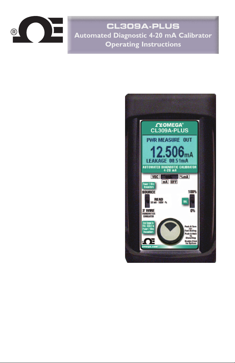
With the CL309A-PLUS you can check, calibrate and measure all your current signal
instruments in a 4 to 20 milliamp DC loop. It can be used at any access point in your loop.
Source & Read 0.000 to 24.000 mA, Simulate a 2 Wire Transmitter or use the CL309A-PLUS to
simultaneously power your 2 Wire Transmitter and measure its output.
• EASY TO READ
Turn on the backlight to easily read the display in
dark areas of the plant.
• TROUBLESHOOT LOOP PROBLEMS
Quickly diagnose ground fault and current
leakage with the patented loop diagnostic
technology (US Patent# 7,248,058).
• SOURCE MILLIAMPS
Calibrate recorders, digital indicators, stroke
valves or any instruments that get their input
from a 4 to 20 mA loop. Easily set any value
quickly to within 0.001 mA with the adjustable
digital potentiometer “DIAL” or use preset 4.000
mA (0.00%) and 20.000 mA (100.00%)
• AUTOMATIC OUTPUT STEPPING & RAMPING
Press & hold the dial to automatically step from 4
to 20 in 2, 3 or 5 steps or choose a continuous
ramp.
• CALIBRATE USING LOOP POWER
Check loop wiring and receivers by using the
CL309A-PLUS in place of a 2 Wire transmitter.
The CL309A-PLUS uses any loop power from 2
to 60 V DC.
• READ LOOP CURRENT
Check controller outputs or measure the milliamp
signal anywhere in the loop. The CL309A-PLUS
measures 0.000 to 24.000 mA (-25.00 to 125.00%)
signals with greater accuracy than a typical
multimeter.
• POWER & MEASURE 2 WIRE TRANSMITTERS
The CL309A-PLUS can simultaneously output
process loop using the internal batteries and internal switching power supply, while measuring
the output of a 2 Wire Transmitter and any other loop devices. Powers HART™ transmitters with
built-in 250 ohm resistor simplifying hookups with HART communicators.
• READ DC VOLTS
The CL309A-PLUS can measure from -60.00 to +60.00 VDC with 10mV resolution. Use it to
check loop power supplies, I/V converters, 1 to 5 Volt signals, and other voltages making it
unnecessary to carry an additional multimeter.
24V DC to power any and all devices in a
Page 1
Page 4
Basic Operation
5
OUT
4- 20 m A
mA OFF
mA
DIAL
Push & Turn
Fast Dialing
Push & Hold
Store/Step
Double Click
for Options
100%
for
to
0%
3
20.000
AUTOMATED DIAGNOSTIC CALIBRATOR
VDC %mA
Power 2 Wire
Transmi tters
Dial Ou tput t o
FULL SC ALE to
Power 2 Wire
Transmi tters
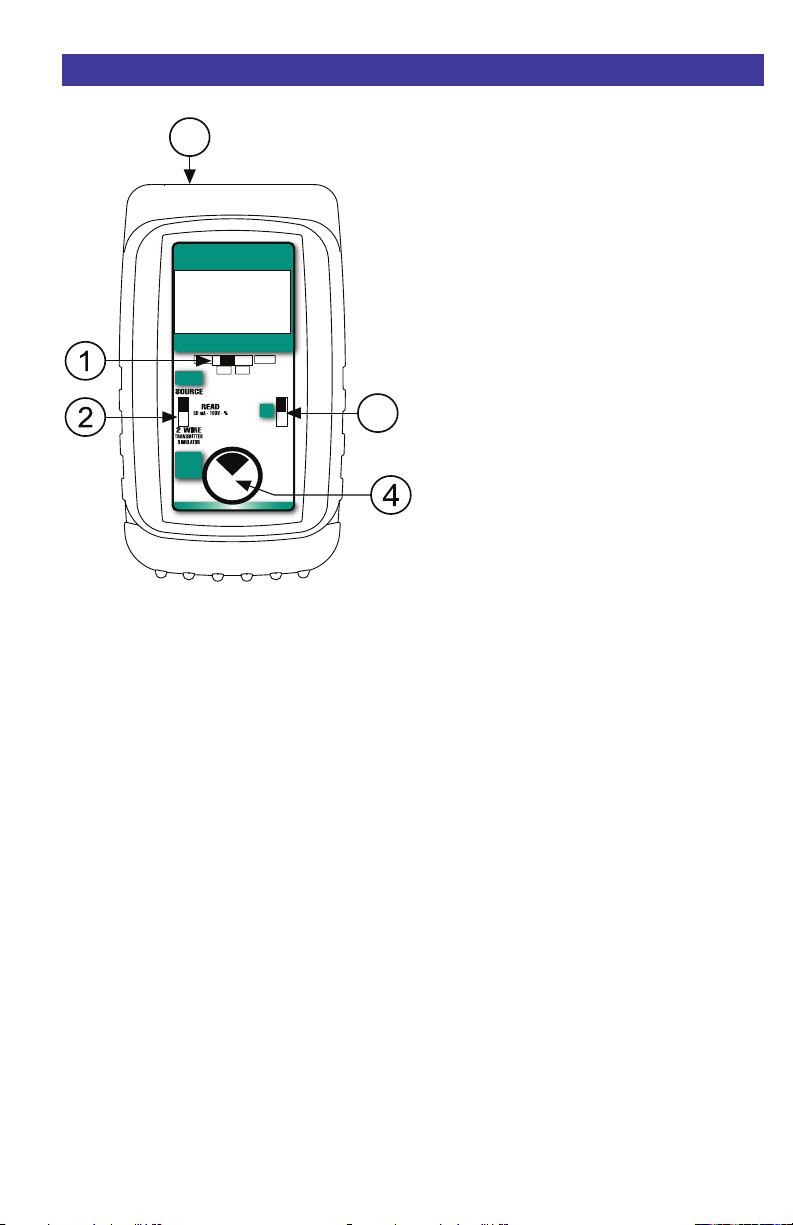
1 POWER SWITCH
Select “mA” to display and calibrate in milliamps.
Select “% 4 to 20 mA” to display and calibrate
in percent. Select “READ VDC” to read volts
DC. Return the slide switch to the “OFF”
position when not in use.
Note:
Percent mode can also be used with chart
recorders, valves or current trips that display in
percent.
100.00% = 20.000 mA
75.00% = 16.000 mA
50.00% = 12.000 mA
25.00% = 8.000 mA
0.00% = 4.000 mA
To convert from Milliamps to Percent:
Percent = (Milliamps - 4) / 0.16
To convert from Percent to Milliamps:
Milliamps = Percent / 6.25 + 4
2 SOURCE / READ / 2 WIRE SWITCH
Select “SOURCE” to output in mA or percent.
Select “READ” to read in mA or percent.
Select “2 WIRE” to simulate a 2 Wire Transmitter.
3 OMEGA SWITCH
Instantly output 4.000 mA or 20.000 mA by moving
the OMEGA
position or “20.00mA”/“100.0%” position.
three point checks select the “DIAL” position.
The CL309A-PLUS will remember the last
“DIAL” value, even with the power off.
Note: The same “DIAL” value is stored for both
mA and %. The recalled value will be displayed
in the units selected.
®
switch to the “4.00mA” /“0.0%”
For fast
4 DIAL KNOB
Turn the knob to adjust output level. Turn
clockwise to increase the output, counter
clockwise to decrease the output 0.001 mA
(0.01%) at a time. Push and turn the knob for
faster dialing adjusting 0.100 mA (1.00%) at a
time. Press and Hold the knob to start automatic
stepping or ramping. Double click the knob for
stepping and Ground Leak Detection setup.
EXTERNAL POWER JACK (Not Shown)
5
When used with the optional AC Adaptor, the
external power jack will eliminate the drain on
your batteries. This is handy for jobs that require
extended bench use of the CL309A-PLUS.
See accessories (page 10) for ordering information.
Note: This feature does not charge the batteries,
it only supplies power to the CL309A-PLUS.
CHANGING BATTERIES
Low battery is indicated by “BAT” on the display.
Approximately one to four hours of typical
operation remain before the 434 will automatically
turn off. To change the batteries; remove th
rubber boot, remove the battery door from the
back of the unit by sliding the door downward.
This allows access to the battery compartment.
Replace with four (4) “AA” 1.5V batteries being
careful to check the polarity. Replace the battery
door & replace the boot. All stored configuration
options are reset to factory settings when the
batteries are removed.
Note: Alkaline batteries are supplied and
recommended for maximum battery life &
performance.
e
Page 2
Page 5

Configuration
Configure the Calibrator
Move
1 POWER SWITCH to “mA”, “% 4 to 20
mA” or “READ VDC”.
The following display will appear for 3 seconds:
CL309A-PLUS REV #.#
Double click the
unit is on and the following display will appear
for 30 seconds:
> EXIT MENU
STEPS 5
GND LEAK DET OFF
BACKLIGHT OFF
HART MODE OFF
> EXIT MENU
AUTO OFF OFF
Turn the
menu. Press the 4 DIAL KNOB to toggle
between OFF and ON. These settings are
remembered even with the power off.
EXIT MENU - exits this menu immediately and
saves any changes. Menu will automatically exit
after 30 seconds of inactivity.
4 DIAL KNOB at any time the
4 DIAL KNOB to move through the
STEPS - pressing the knob will cycle from 2, 3,
5 steps and RAMP.
2 steps will automatically switch between 4 &
20 mA (0 & 100%).
3 steps between 4, 12 & 20 mA (0, 50 &
100%).
5 steps between 4, 8, 12, 16 & 20 mA (0, 25,
50, 75 & 100%).
RAMP will continuously ramp the output
between 4 & 20 mA (0 & 100%).
GROUND LEAK DETECTION - when ON the
CL309A-PLUS has the ability to check for
current leaks caused by ground faults, moisture
or corrosion. This operates in Power/Measure
mode while powering up a 2-wire transmitter or
loop.
BACKLIGHT - If BACKLIGHT is ON the
backlight will light all the time the unit is powered
up. For maximum battery life turn the backlight
off when using the CL309A-PLUS in areas
enough ambient light to read the display.
HART MODE - when ON a 250 Ohm resistor is
automatically inserted in series with the leads in
all modes. This allows a HART Communicator to
communicate with a HART Transmitter without
adding an external resistor in the loop.
AUTO OFF - If AUTO OFF is ON, the unit will
turn off after 30 minutes of inactivity to save
battery life. If AUTO OFF is OFF the unit will stay
on until the POWER SWITCH is moved to the off
position.
Note: All settings are remembered even with the
power off. Removing the batteries resets the
values to factory defaults.
with
Page 3
Page 6
Sourcing Milliamps
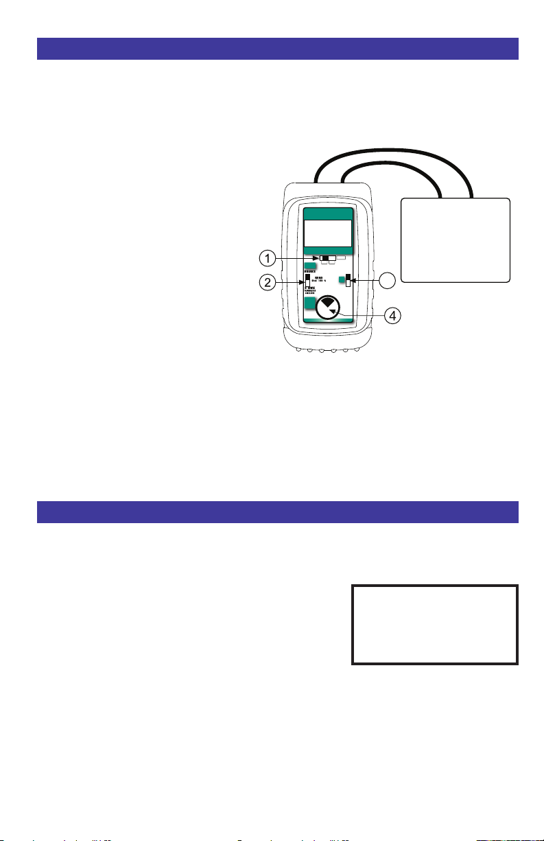
mA OUT, % OUT (Percent of 4 to 20 mA)
Choose this function to provide an output from 0.000 to 24.000 milliamps. The compliance voltage
is a nominal 24 VDC to provide the driving power to your milliamp receivers.
1) Disconnect one or both input wires from
the device to be calibrated.
2) Select “mA” or “% 4 to 20mA” with slide
3) Select “SOURCE” using slide switch
4) Connect the output leads of the CL309A-
The output is adjusted in 0.001 mA (0.01%)
increments by turning the knob
O M EG A s wi tc h
position, or the current can be set at the fixed
points of 4.000mA (0.00%) or 20.000mA
(100.00%) with switch
knob for faster dialing with 0.100 (1.00%)
increments.
1.
switch
2.
PLUS to the inputs of the device being
calibrated, making sure to check polarity.
Red lead to the plus (+) input and black
lead to the minus (-) input.
4 while the
3 i s in th e “ DI AL ”
3. Press and turn the
20.000
AUTOM ATED DIAGNO STIC C ALIBRAT OR
4-20 mA
VDC %mA
mA OFF
Power 2 Wire
Transmitters
DIAL
Dial Output to
FULL SCALE to
Power 2 Wire
Transmitters
Milliamp Receiver Input
OUT
mA
100%
3
0%
Push & Turn
for
Fast Dialing
Push & Hold
to
Store/Step
Double Click
for Options
Controller
Transmitter
Computer
Logger
I/P
DCS
Start automatic stepping or ramping by pressing and holding the
4 DIAL KNOB for 3 seconds. The
word STEPPING or RAMPING will flash on the display anytime the selected automatic function is
running. The CL309A-PLUS will automatically step or ramp between 4mA & 20mA (or 20mA & 4mA)
for 30 seconds then reverse direction. Stop the stepping or ramping by pressing or turning the knob
or moving any switch.
Using Automatic Stepping & Ramping
Using Automatic STEP & RAMP output
Move 1 POWER SWITCH to “mA”, or “% 4 to 20 mA” and
the 2 SOURCE / READ / 2 WIRE SWITCH to “SOURCE” or “2 WIRE”.
The starting point for automatic stepping & ramping is based
on the
3 OMEGA S W I T C H . Place t h e O M EGA swit c h
at 20 mA and the automatic stepping or ramping will start at
20.000 mA (100.00%) and the values will decrease. Place the
OM EGA swi tch at 4 mA an d th e a utom ati c st epp ing or
ramping will start at 4.000 mA (0.00%) and the values will
increase.
Start automatic stepping or ramping by pressing and holding the
word STEPPING or RAMPING will flash on the display anytime the selected automatic function is
running. The CL309A-PLUS will automatically step or ramp between 4mA & 20mA (or 20mA & 4mA)
for 30 seconds then reverse direction. Stop the stepping or ramping by pressing or turning the knob
or moving any switch.
STEPPING OUT
12.000 mA
4 DIAL KNOB for 3 seconds. The
Page 4
Page 7

Simulate 2-Wire Transmitters
2 Wire mA, 2 Wire % (Percent of 4 to 20 mA)
Choose this function to simulate a 2 Wire Transmitter output from 0.000 to 24.000 milliamps.
Operates in loops with power supply voltages from 2 to 100 VDC
1) Disconnect one or both input wires
from the device to be calibrated.
2) Select “mA” or “% 4 to 20mA” with
slide switch
1.
3) Select “2 WIRE” using slide switch
2.
4) Connect the red input lead of the
434 to the plus (+) input of the field
connections and the black lead to
the minus (-).
Receiver
Powers External
2-Wire Transmitter
Power Supply
(2 to 100 VDC)
2 WIRE
12.004
AUTOMAT ED D IAGNOS TIC CA LIBRATOR
4-20 mA
VDC %mA
mA OFF
Power 2 Wire
Transmitters
DIAL
Dial Output to
FULL SCALE to
Push & Turn
Power 2 Wire
Fast Dialing
Transmitters
Push & Hold
Store/Step
Double Click
for Options
mA
100%
0%
for
to
Loop current is adjusted in 0.001 mA (0.01%) increments by turning the knob
OMEGA s wi tch
4.000mA (0.00%) or 20.000mA (100.00%) with switch
3 is in the “ DIAL” position, or the current can be set at the fixed p oi nts of
3. Press and turn the knob for faster dialing
To
Sensor
(Disconnected)
+ IN - REF +OUT-
Typical
2-Wire
Transmitter
4 while the
with 0.100 (1.00%) increments.
Start automatic stepping or ramping by pressing and holding the
4 DIAL KNOB for 3 seconds. The
word STEPPING or RAMPING will flash on the display anytime the selected automatic function is
running. The CL309A-PLUS will automatically step or ramp between 4mA & 20mA (or 20mA & 4mA)
for 30 seconds then reverse direction. Stop the stepping or ramping
by pressing or turning the knob
or moving any switch.
Setting Up Automatic Stepping & Ramping
To change the Automatic Stepping & Ramping settings
Double click the 4 DIAL KNOB at any time the unit is on and the following display will appear for 30
seconds:
Turn the
and ON or to change the steps setting. These settings are remembered even with the power off.
4 DIAL KNOB to move through the menu. Press the 4 DIAL KNOB to toggle bet ween OFF
EXIT MENU - exits this menu immediately and saves any changes. Menu will automatically exit after
30 seconds of inactivity.
STEPS - pressing the knob will cycle from 2, 3, 5 steps and RAMP.
2 steps will automatically switch between 4 & 20 mA (0 & 100%).
3 steps between 4, 12 & 20 mA (0, 50 & 100%).
5 steps between 4, 8, 12, 16 & 20 mA (0, 25, 50, 75
& 100%).
RAMP will continuously ramp the output between 4 & 20 mA (0 & 100%).
Page 5
Page 8
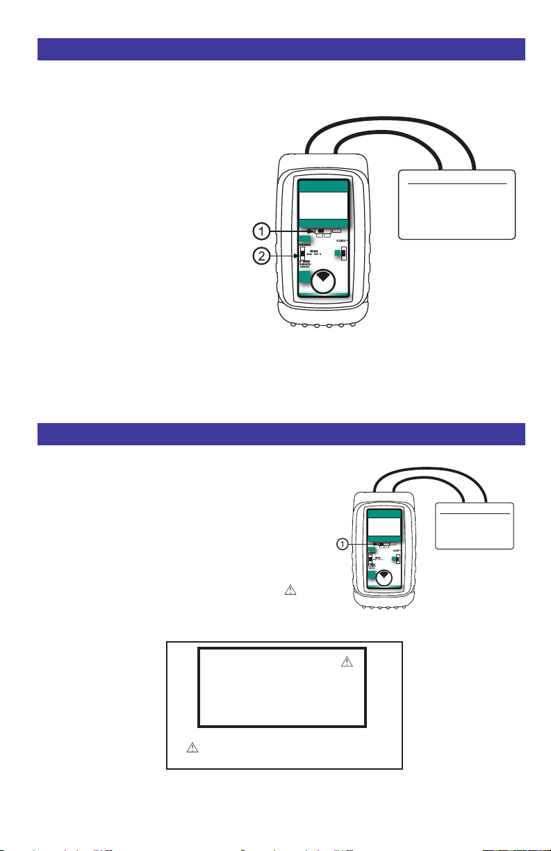
Reading Milliamp Outputs
Voltage to be Measured
Battery
Loop Power Supply
Transmitter Voltage Drop
1 to 5 Volt Loops
Power 2 Wire
Transmitters
Dial Output to
FULL SCALE to
Power 2 Wire
Transmitters
DIAL
AUTOMATE D DIA GNOSTI C CALI BRATOR
4-20 m A
Push & Hold
to
Store/Step
Push & Turn
for
Fast Dialing
Double Click
for Options
VDC %mA
mA OFF
100%
0%
24.34
READ
V
READ mA, READ % (Percent of 4 to 20 mA)
Choose this function to measure from 0.000 to 24.000 milliamps or -25.00 to 125.00%.
1) Open the current loop at any convenient point along the signal path.
2) Select “mA” or “% 4 to 20mA” with slide
1.
switch
3) Select “Read” using slide switch
2.
4) Connect the red input lead (+) of the
CL309A-PLUS to the more positive
point of the break and the black input to
the more negative point.
Signals below 0 mA or open circuits are
indicated by 0.000 mA (-25.00%) on the
display. Signals above 52 mA are current
READ
4.340
mA
AUTOM ATED DIAGNO STIC C ALIBRAT OR
4-20 mA
VDC %mA
mA OFF
Power 2 Wire
Transmitters
DIAL
Dial Output to
FULL SCALE to
Push & Turn
Power 2 Wire
Fast Dialing
Transmitters
Push & Hold
Store/Step
Double Click
for Options
100%
0%
for
to
Milliamp Output Signal
Controller
Transmitter
P/I
DCS
limited by protection circuitry and
“OVERRANGE” is flashed on the display.
Read DC Volts
READ V
Choose this function to measure from -99.99 to +99.99V DC.
1) Select “VDC” with slide switch
1.
2) Connect the red (+) and black (-) leads of the CL309APLUS across the voltage source to be measured.
Any DC voltage from -60.00 to +60.00 volts may be
measured. Loop power supplies, signal voltages at receivers,
batteries and transmitter voltage drops may be measured.
Signals exceeding ±60.00 VDC are indicated by on the
display. Signals exceeding ±99.99 VDC will be indicated by
“OVERRANGE” flashing on the display.
READ
72.83 V
Signals exceeding ±60.00 VDC are indicated
Page 6
by on the display.
Page 9
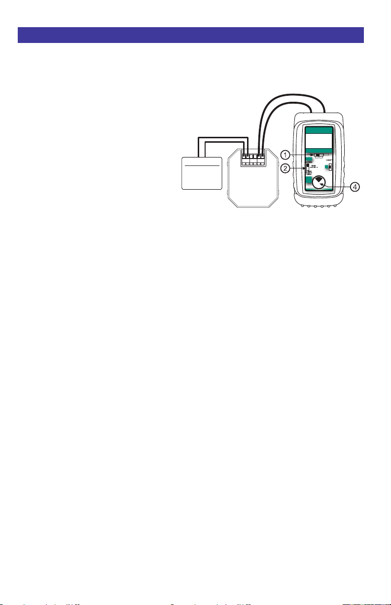
Power & Measure 2-Wire Transmitters
mA OUT, % OUT (Percent of 4 to 20 mA)
Choose this function to simultaneously supply power to a 2 Wire Transmitter while displaying the 4
to 20 mA output of the transmitter.
1) Disconnect one or both input wires from
the device to be calibrated.
2) Select “mA” or “% 4 to 20mA” with slide
3) Select “SOURCE” using slide switch
4) Press and turn the knob
5) Connect the red source lead of the
1.
switch
2.
4 clockwise
several times until full scale output
mA/125.00%) is obtained. The display will
indicate “PWR MEASURE”.
CL309A-PLUS to the plus (+) input of the
device and the black source lead to the
minus (-).
(24.000
Transmitter Input
Sensor
Process Signal
Simulated Input
+ IN - REF +OUT-
Typical
2-Wire
Transmitter
25.42
AUTOMAT ED DI AGNOST IC CAL IBRATOR
4-20 mA
VDC %mA
mA OFF
Power 2 Wire
Transmitters
Dial Output to
FULL SCALE to
Power 2 Wire
Transmitters
OUT
%
100%
DIAL
0%
Push & Turn
for
Fast Dialing
Push & Hold
to
Store/Step
Double Click
for Options
The CL309A-PLUS supplies a nominal 24 volts DC at 24 mA to the 2 Wire Transmitter. The current
passed by the transmitter will be accurately displayed by the CL309A-PLUS.
Calibrate the transmitter
in the usual manner and disconnect the CL309A-PLUS. If Ground Leak Detection is enabled the
amount of milliamps leaking in the transmitter or loop is indicated on the display.
Page 7
Page 10
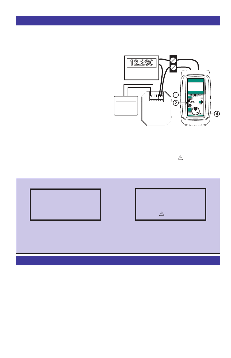
Using Ground Leak Detection
mA OUT, % OUT (Percent of 4 to 20 mA)
Find current leaks in loops caused by ground faults, moisture or corrosion. The 434 simultaneously
supplies power to a 2 Wire Transmitter (or loop with a transmitter) while displaying the 4 to 20 mA
output and the amount of current leaking in the loop.
1) Disconnect one or both input wires from
the device to be calibrated.
Select “mA” or “% 4 to 20mA” with slide
2)
3)
1.
switch
Select “SOURCE” using slide switch 2.
4) Turn the knob 3 clockwise several times
until full scale output (>24.000
mA/125.00%) The display will indicate
“PWR MEASURE” and “LEAKAGE:”
5) Connect the red source lead of the
12.280
INDICATOR
Transmitter Input
Sensor
Process Signal
Simulated Input
PROCESS
+ IN - REF +OUT-
Typical
2-Wire
Transmitter
PWR MEASURE OUT
12.280
LEAKAGE: 00.28mA
AUTOMAT ED DI AGNOST IC CAL IBRATOR
4-20 mA
VDC %mA
mA OFF
Power 2 Wire
Transmitters
Dial Output to
FULL SCALE to
Power 2 Wire
Transmitters
mA
100%
DIAL
0%
Push & Turn
for
Fast Dialing
Push & Hold
to
Store/Step
Double Click
for Options
CL309A-PLUS to the plus (+) input of the
device and the black source lead to the
minus (-).
The CL309A-PLUS supplies a nominal 24 volts DC at 24 mA to the 2 Wire Transmitter or loop. The
current passed by the transmitter will be accurately displayed by the CL309A-PLUS along with an
indication of leakage current at the bottom of the display. If there is an uncontrolled loop, a transmitter
with upscale burnout and bad or missing sensor or a short the display shows “ LOOP > 24mA”
Note: Many installed transmitters will normally indicate 0.01 to 0.10 mA leakage without significant
control problem. Unstable readings may indicate loose connections or the presence of moisture.
Typical Error Conditions
PWR MEASURE OUT
12.280 mA
LEAKAGE: 0 0.28mA
The CL309A-PLUS is supplying the loop
voltage. A calibrated transmitter is limiting the
loop current to 12.00 mA. An additional 0.28
mA is not controlled by the transmitter and is
leaking somewhere in the loop.
PWR MEASURE OUT
24.179 mA
LOOP > 24mA
The CL309A-PLUS is supplying the loop
voltage. There is an control loop error. This
may be a transmitter (set for upscale burnout)
with a bad or missing sensor, or a short in the
loop.
Setting Up Ground Leak Detection
Enabling Ground Leak Detection
Double click the 4 DIAL KNOB at any time the unit is on and the following display will appear for 30
seconds:
Turn the
and ON or to change the steps setting. These settings are remembered even with the power off.
EXIT MENU - exits this menu immediately and saves any changes. Menu will automatically exit after
30 seconds of inactivity.
GROUND LEAK DETECTION - when ON the CL309A-PLUS has the ability to check for current
leaks caused by ground faults, moisture or corrosion that bypass the current control element or
transmitter.
Page 8
4 DIAL KNOB to move through the menu. Press the 4 DIAL KNOB to toggle bet ween OFF
Page 11

Application Notes
GROUND LEAK DETECTION
If you find a loop where the transmitter is
calibrate correctly but all the readings elsewhere
in the loop have a fixed offset this is due to a
zero shift. This zero shift is caused by some
current in the loop bypassing the transmitter.
This might be caused by ground faults, moisture
or corrosion.
If you have some loops that are erratic after it
rains there may be moisture present in a junction
box or where insulation has broken down. Turn
on Ground Leak Detection and use the CL309APLUS to power up the loop. Any current that isn’t
controlled by the transmitter or other current
control element will be indicated as leakage on
the CL309A-PLUS display.
The CL309A-PLUS powers up the 2-Wire
transmitter
and the uncontrolled current. This provides
information useful in troubleshooting loop errors.
OUT OF RANGE SIGNALS
Signals below 0 mA or open circuits are indicated
by 0.000 mA (-25.00%) on the display. Signals
above 24 mA are current limited by protection
circuitry to approximately 25 mA.
KEEPING THE PROCESS GOING
When an instrument in a critical control loop
develops a problem it is important to maintain
control of the process. The CL309A-PLUS can
be substituted for a faulty controller or transmitter
to provide temporary manual control of the
process. One technician takes manual control of
the process while a second technician retrieves,
installs and configures a replacement instrument.
OPEN LOOPS
The display will indicate ERROR
or -25.00% if there is an open loop or if the
polarity is reversed. Check all the connections in
the loop or try reversing the leads.
or loop and indicates the total current
and 0.000 mA
POWER TRANSMITTER
Adjusting the SOURCE output to full scale (>24
mA) supplies a nominal 24V DC to power a 2
Wire Transmitter while simultaneously displaying
the 4 to 20 mA output of the transmitter.
READ MILLIAMPS
Select READ milliamps by moving slide switch
1 to “mA” or “% 4 to 20mA” and moving slide
switch 2 to “READ”. Place the CL309A-PLUS in
the loop in series with the current to be
measured.
SOURCE MILLIAMPS or 2-WIRE SIMULATOR
Select “SOURCE” using slide switch 2 to output
from 0.000 to 24.000 milliamps using the
CL309A-PLUS’s internal power source. This will
provide 24V DC. Select “2-WIRE” to control the
current in a loop that is using
supply.
To change the output current adjust the dial
4 . Turning clockwise will increase the
knob
output value, turning counter-clockwise will
decrease the output value with 0.001 mA
(0.01%) resolution. Press and turn the knob for
T h e ou t pu t i s ad j us tab l e i n a ll O M EG A
positions.
When returning to the “4.00mA”/“0.0%” and
“20.00mA”/”100%” positions they will always
return to 4.00 (0.0%) and 20.00 (100.0%) mA.
This method is superior to keypad units. The
zero and full scale positions can be adjusted
smoothly making easy valve end stop testing,
trip point testing, alarm testing, etc. There is
virtually no overshoot/undershoot simplifying
testing.
READ DC VOLTS
Select “VDC” using slide switch
DC. Clip the leads across the voltage to be
measured.
an existing power
1 to read volts
.noituloser )%00.1( Am 001.0 htiw gnilaid retsaf
Page 9
Page 12

Stroking Valves
SETTING UP VALVES
When setting up a valve it is important to correctly set the end stops. Use the CL309A-PLUS to
supply the 4 to 20 mA control signal to stroke the valve. Select “SOURCE” and the CL309A-PLUS
will use the internal power source for outputting current or switch to 2-WIRE SIMULATOR to stroke
a valve using any pre-existing installed loop power supply as the power source.
Example:
1) Disconnect the 4-20 mA control wires from the Current-to Pressure (I/P) converter or the actuator.
2) Connect the CL309A-PLUS following the connection diagrams on the previous pages for
Simulate 2-Wire Transmitters
3) Move the OMEGA switch 3 to “4.00 mA”/”0.0%” and adjust the full y closed stop on th e
actuator.
4) Turn the CL309A-PLUS’s knob
don’t move.
5) Move the OMEGA switch
CL309A-PLUS’s knob
6) Move the OMEGA switch
actuator.
7) Turn the CL309A-PLUS’s knob
move. Repeat steps 6 & 7 until no movement is detected.
8) Move the OMEGA switch
the CL309A-PLUS’s knob counterclockwise. The actuator and valve should begin to move
Repeat steps 3 & 4 until no movement is detected.
4 clockwise. The actuator and valve should begin to move.
4 slowly counterclockwise and verify that the actuator and valve
3 to DIAL and quickly back to “4.00 mA”/”0.0%” then turn the
3 to “20.00 mA”/”100.0%” and adjust the fully open stop on the
4 slowly clockwise and verify that the actuator and valve don’t
3 to DIAL and quickly back to “20.00 mA”/”100.0%” then turn
.
Additional Information
This product is calibrated on equipment traceable to NIST and includes a Certificate of Calibration.
OMEGA ENGINEERING, INC. recommends a calibration interval of one year. Contact your local
representative for recalibration and repair services.
Page 10
Page 13
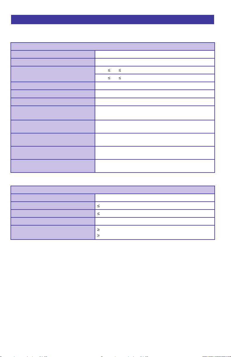
CL309A-PLUS Specifications
(Unless otherwise indicated all specifications are rated from a nominal 23 °C,
70 % RH for 1 year from calibration)
General
Operating Temperature Range -20 to 60 °C (-5 to 140 °F)
Storage Temperature Range -30 to 60 °C (-22 to 140 °F)
Relative Humidity Range 10 % RH 90 % (0 to 35 °C), Non-condensing
10 % RH 70 % (35 to 60 °C), Non-condensing
Size 5.63 x 3.00 x 1.60 inches, 143 x 76 x 41 mm (L x W x H)
Weight 12.1 ounces, 0.34 kg (including boot & batteries)
Batteries Four “AA” Alkaline 1.5V (LR6)
Optional AC Adaptors 120 VAC 50/60 Hz [Part # 020-0100]
240 VAC 50/60 Hz [Part # 020-0101]
Optional NiMh
Low Battery Low battery indication with nominal 1 hour of operation
Protection against misconnection Over-voltage protection to 135 vrms (rated for 30 seconds)
Display High contrast graphic liquid crystal display with 0.315” (8.0
Rechargeable battery kit
120 VAC for North America Only; charger, four
batteries, AC & DC cords [Part # 020-0103]
left
or 240 vrms (rated for 15 seconds)
mm) high digits. LED backlighting for use in low lit areas.
NiMh
Read mA
Ranges and Resolution
Accuracy ± (0.01 % of Reading +0.002 mA)
Voltage burden 2V at 50 mA
Overload/Current limit protection 25 mA nominal
Battery life 125 Hours nominal
0.000 to 24.000 mA or -25.00 to 125.00% of 4-20 mA
100 hrs with backlight on
Page 11
Page 14
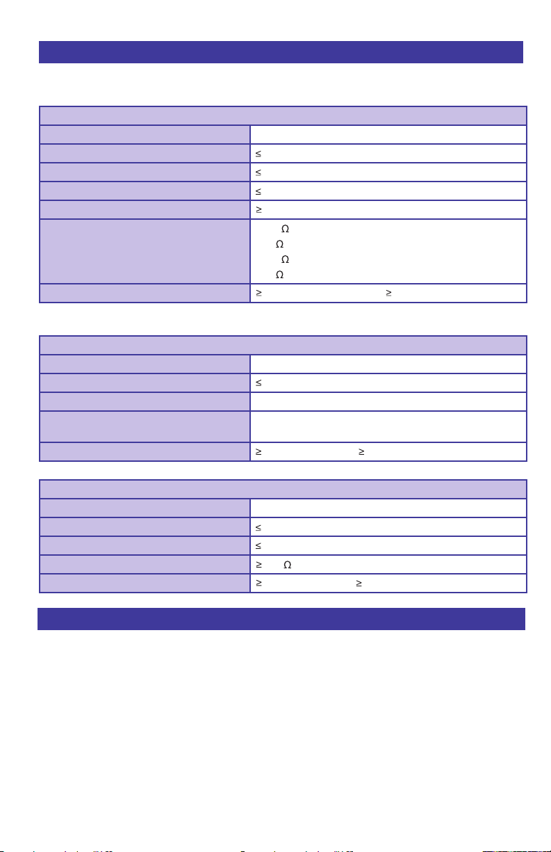
CL309A-PLUS Specifications (continued)
(Unless otherwise indicated all specifications are rated from a nominal 23 °C,
70 % RH for 1 year from calibration)
Source/Power & Measure Two Wire Transmitters
Ranges and Resolution 0.000 to 24.000 mA or -25.00 to 125.00% of 4-20 mA
Accuracy ± (0.01 % of Reading +0.002 mA)
Noise ± ½ Least Significant Digit
Temperature effect ± 0.005 %/°C of FS
Loop compliance voltage
Loop drive capability - Leak Detection Off
Loop drive capability - Leak Detection On
Battery life 30 hrs at 12 mA nominal; 25 hrs with backlight on
2-Wire Transmitter Simulation
Accuracy Same as Source/Power & Measure
Voltage burden 2V at 20 mA
Overload/Current limit protection 24 mA nominal
Loop voltage limits 2 to 60 VDC (fuse-less protected from reverse polarity
Battery life 125 hours nominal; 100 hrs with backlight on
24 DCV @ 20.00mA
1200 at 20 mA for 15 hours nominal;
950 with Hart Resistor enabled
1000 at 20 mA for 15 hours nominal;
750 with Hart Resistor enabled
connections)
Voltage Read
Range and Resolution -60.00 to +60.00 VDC Full Span (FS)
Accuracy ± 0.05 % of FS
Temperature effect ± 100 ppm/°C of FS
Input r
esistance 2 M
Battery life 125 hours nominal; 100 hrs with backlight on
Accessories
INCLUDED:
Carrying Case with Belt Loop Part No. SC-530
Test Leads - one pair: 1 meter (3') long with Part No. 020-0207
retractable shield banana plug & alligator clips
OPTIONAL:
AC ADAPTOR (200 to 240 VAC) Part No. CL530-ADAPTOR-220
AC ADAPTOR (100 to 120 VAC) Part No. CL530-ADAPTOR
Page 12
Page 15

WARRANTY/ DISCLAIMER
OMEGA ENGINEERING, INC. warrants this unit to be free of defects in materials and
workmanship for a period of 37 months from date of purchase. OMEGA’s WARRANTY adds
an additional one (1) month grace period to the normal three (3) year product warranty to
cover handling and shipping time. This ensures that OMEGA’s customers receive maximum
coverage on each product.
If the unit malfunctions, it must be returned to the factory for evaluation. OMEGA’s Customer
Service Department will issue an Authorized Return (AR) number immediately upon phone or
written request. Upon examination by OMEGA, if the unit is found to be defective, it will be
repaired or replaced at no charge. OMEGA’s WARRANTY does not apply to defects resulting
from any action of the purchaser, including but not limited to mishandling, improper
interfacing, operation outside of design limits, improper repair, or unauthorized modification.
This WARRANTY is VOID if the unit shows evidence of having been tampered with or shows
evidence of having been damaged as a result of excessive corrosion; or current, heat, moisture
or vibration; improper specification; misapplication; misuse or other operating conditions
outside of OMEGA’s control. Components in which wear is not warranted, include but are not
limited to contact points, fuses, and triacs.
OMEGA is pleased to offer suggestions on the use of its various products. However,
OMEGA neither assumes responsibility for any omissions or errors nor assumes
liability for any damages that result from the use of its products in accordance with
information provided by OMEGA, either verbal or written. OMEGA warrants only
that the parts manufactured by the company will be as specified and free of
defects. OMEGA MAKES NO OTHER WARRANTIES OR REPRESENTATIONS OF ANY
KIND WHATSOEVER, EXPRESSED OR IMPLIED, EXCEPT THAT OF TITLE, AND ALL
IMPLIED WARRANTIES INCLUDING ANY WARRANTY OF MERCHANTABILITY AND
FITNESS FOR A PARTICULAR PURPOSE ARE HEREBY DISCLAIMED. LIMITATION OF
LIABILITY: The remedies of purchaser set forth herein are exclusive, and the total
liability of OMEGA with respect to this order, whether based on contract, warranty,
negligence, indemnification, strict liability or otherwise, shall not exceed the
purchase price of the component upon which liability is based. In no event shall
OMEGA be liable for consequential, incidental or special damages.
CONDITIONS: Equipment sold by OMEGA is not intended to be used, nor shall it be used: (1)
as a “Basic Component” under 10 CFR 21 (NRC), used in or with any nuclear installation or
activity; or (2) in medical applications or used on humans. Should any Product(s) be used in or
with any nuclear installation or activity, medical application, used on humans, or misused in
any way, OMEGA assumes no responsibility as set forth in our basic WARRANTY/ DISCLAIMER
language, and, additionally, purchaser will indemnify OMEGA and hold OMEGA harmless from
any liability or damage whatsoever arising out of the use of the Product(s) in such a manner.
RETURN REQUESTS/INQUIRIES
Direct all warranty and repair requests/inquiries to the OMEGA Customer Service Department.
BEFORE RETURNING ANY PRODUCT(S) TO OMEGA, PURCHASER MUST OBTAIN AN
AUTHORIZED RETURN (AR) NUMBER FROM OMEGA’S CUSTOMER SERVICE DEPARTMENT
(IN ORDER TO AVOID PROCESSING DELAYS). The assigned AR number should then be
marked on the outside of the return package and on any correspondence.
The purchaser is responsible for shipping charges, freight, insurance and proper packaging to
prevent breakage in transit.
FOR WARRANTY
RETURNS, please have
the following information available BEFORE
contacting OMEGA:
1. Purchase Order number under which
the product was PURCHASED,
2. Model and serial number of the product
under warranty, and
3. Repair instructions and/or specific
problems relative to the product.
FOR NON-WARRANTY REPAIRS,
consult
OMEGA for current repair charges. Have the
following information available BEFORE
contacting OMEGA:
1. Purchase Order number to cover the
COST of the repair,
2. Model and serial number of theproduct, and
3. Repair instructions and/or specific problems
relative to the product.
OMEGA’s policy is to make running changes, not model changes, whenever an improvement is possible.
This affords our customers the latest in technology and engineering.
OMEGA is a registered trademark of OMEGA ENGINEERING, INC.
© Copyright 2011 OMEGA ENGINEERING, INC. All rights reserved. This document may not be copied, photocopied,
reproduced, translated, or reduced to any electronic medium or machine-readable form, in whole or in part, without
the prior written consent of OMEGA ENGINEERING, INC.
Page 16

Where Do I Find Everything I Need for
Process Measurement and Control?
OMEGA…Of Course!
Shop online at omega.com
SM
TEMPERATURE
䡺⻬
Thermocouple, RTD & Thermistor Probes, Connectors, Panels & Assemblies
䡺⻬
Wire: Thermocouple, RTD & Thermistor
䡺⻬
Calibrators & Ice Point References
䡺⻬
Recorders, Controllers & Process Monitors
䡺⻬
Infrared Pyrometers
PRESSURE, STRAIN AND FORCE
䡺⻬
Transducers & Strain Gages
䡺⻬
Load Cells & Pressure Gages
䡺⻬
Displacement Transducers
䡺⻬
Instrumentation & Accessories
FLOW/LEVEL
䡺⻬
Rotameters, Gas Mass Flowmeters & Flow Computers
䡺⻬
Air Velocity Indicators
䡺⻬
Turbine/Paddlewheel Systems
䡺⻬
Totalizers & Batch Controllers
pH/CONDUCTIVITY
䡺⻬
pH Electrodes, Testers & Accessories
䡺⻬
Benchtop/Laboratory Meters
䡺⻬
Controllers, Calibrators, Simulators & Pumps
䡺⻬
Industrial pH & Conductivity Equipment
DATA ACQUISITION
䡺⻬
Data Acquisition & Engineering Software
䡺⻬
Communications-Based Acquisition Systems
䡺⻬
Plug-in Cards for Apple, IBM & Compatibles
䡺⻬
Data Logging Systems
䡺⻬
Recorders, Printers & Plotters
HEATERS
䡺⻬
Heating Cable
䡺⻬
Cartridge & Strip Heaters
䡺⻬
Immersion & Band Heaters
䡺⻬
Flexible Heaters
䡺⻬
Laboratory Heaters
ENVIRONMENTAL
MONITORING AND CONTROL
䡺⻬
Metering & Control Instrumentation
䡺⻬
Refractometers
䡺⻬
Pumps & Tubing
䡺⻬
Air, Soil & Water Monitors
䡺⻬
Industrial Water & Wastewater Treatment
䡺⻬
pH, Conductivity & Dissolved Oxygen Instruments
M4836/0511
 Loading...