

Page 1
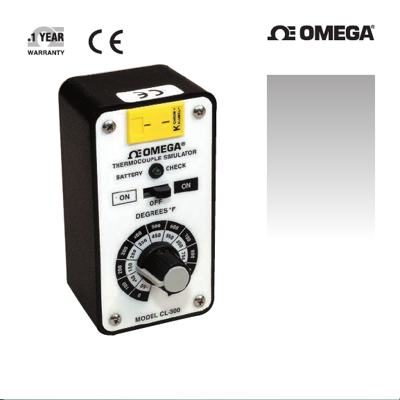
User’s Guide
Shop online at
omega.com
e-mail: [email protected]
For latest product manuals:
www.omegamanual.info
SM
CL-300, CL-301, CL-302, CL-303
Portable Simulators
Page 2

omega.com [email protected]
Servicing North America:
U.S.A.: Omega Engineering, Inc., One Omega Drive, P.O. Box 4047
Stamford, CT 06907-0047 USA
Toll-Free: 1-800-826-6342 (USA & Canada only)
Customer Service: 1-800-622-2378 (USA & Canada only)
Engineering Service: 1-800-872-9436 (USA & Canada only)
Tel: (203) 359-1660 Fax: (203) 359-770
e-mail: [email protected]
For Other Locations Visit omega.com/worldwide
The information contained in this document is believed to be correct, but OMEGA
accepts no liability for any errors it contains, and reserves the right to alter
specifications without notice.
Page 3

Direct all warranty and repair requests/inquiries to the OMEGA Customer Service
Department. BEFORE RETURNING ANY PRODUCT(S) TO OMEGA, PURCHASER MUST
OBTAIN AN AUTHORIZED RETURN (AR) NUMBER FROM OMEGA’S CUSTOMER
SERVICE DEPARTMENT (IN ORDER TO AVOID PROCESSING DELAYS). The assigned
AR number should then be marked on the outside of the return package and on any
correspondence. The purchaser is responsible for shipping charges, freight, insurance
and proper packaging to prevent breakage in transit.
FOR WARRANTY RETURNS, please
have the following information
available BEFORE contacting OMEGA:
1. Purchase Order number under
which the product was PURCHASED,
2. Model and serial number of the
product under warranty, and
3. Repair instructions and/or specific
problems relative to the product.
OMEGA’s policy is to make running changes, not model changes, whenever an
improvement is possible. This affords our customers the latest in technology and
engineering.OMEGA is a registered trademark of OMEGA ENGINEERING, INC.
© Copyright 2016 OMEGA ENGINEERING, INC. All rights reserved. This document may
not be copied, photocopied, reproduced, translated, or reduced to any electronic medium
or machine-readable form, in whole or in part, without the prior written consent of
OMEGA ENGINEERING, INC.
RETURN REQUESTS / INQUIRIES
FOR NON-WARRANTY REPAIRS,
OMEGA for current repair charges. Have
the following information available BEFORE
contacting OMEGA:
1. Purchase Order number to cover the COST
of the repair,
2. Model and serial number of the product, and
3. Repair instructions and/or specific
problems relative to the product.
consult
Page 4

Notes
Page 5

Table of Contents
Section Page
Model CL-300 Portable
Thermocouple Source..........................................11
Model CL-301 Portable RTD Simulator.................12
Model CL-302 Portable
Transmitter Simulator..........................................21
Model CL-303 Portable
mA Source/2-Wire Simulator..............................30
i
Page 6

Table of Contents
Model CL-300 Portable Thermocouple Source
Section Page
Section 1 Introduction . . . . . . . . . . . . . . . . . . . . . . . . .1
1.1 Description . . . . . . . . . . . . . . . . . . . . . . . . . . . . . . . . . . . . . . . . 1
1.2 Features . . . . . . . . . . . . . . . . . . . . . . . . . . . . . . . . . . . . . . . . . . . 3
Section 2 Installation . . . . . . . . . . . . . . . . . . . . . . . . .3
2.1 Unpacking . . . . . . . . . . . . . . . . . . . . . . . . . . . . . . . . . . . . . . . . 3
Section 3 Operation . . . . . . . . . . . . . . . . . . . . . . . . . .4
3.1 Operating Instructions . . . . . . . . . . . . . . . . . . . . . . . . . . . . . . 4
Section 4 Service Information . . . . . . . . . . . . . . . . . . .5
4.1 Maintenance . . . . . . . . . . . . . . . . . . . . . . . . . . . . . . . . . . . . . . . 5
4.2 Equipment Required for Calibration . . . . . . . . . . . . . . . . . . 5
4.3 Calibration Procedure . . . . . . . . . . . . . . . . . . . . . . . . . . . . . . 5
Section 5 Specifications . . . . . . . . . . . . . . . . . . . . . . .9
ii
Page 7

Section 1 Introduction
1.1 Description
The OMEGA®Model CL-300 Thermocouple Source provides 22 precise
temperature equivalent millivolt signals to transmitters, recorders,
controllers, alarms, data acquisition, and computer systems. Model
CL-300 is cold-junction compensated for ambient temperature
variations and provides a thermocouple connector output. Cables are
available in the desired length and terminal types to exactly duplicate
the thermocouples in the system being tested. Conformity to the
particular thermocouple vs millivolt curve is in accordance with the
latest ASTM and IPTS standards for exact temperature simulation.
Linear millivolt models are also available.
Thermocouple types E, J, K, and T are available in both ˚F and ˚C.
T able 1-1 lists the standard ranges. Resolution is 25˚, 50˚, or 100˚
corresponding to full scale output of 500˚, 1000˚, and 2100˚ respectively.
Dual ranges, with an individual “ON” position for each range, allow
quick, easy settings for any output. Calibrated accuracy is ±0.1% of
span ±1 degree. For negative temperatur es, add ±2 degrees.
T wo internal AA cells provide power for approximately one year of
everyday use. Afront panel LED pulses every time the unit is turned
on to indicate proper battery voltage.
1
Page 8
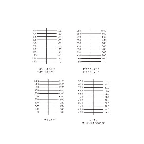
Table 1-1
Model CL-300 Standard Ranges
2
Page 9

1.2 Features
• Calibrate and T roubleshoot Temperatur e Systems
• Simulates Thermocouples J, K, E, T, R, S, or mV Sour ce
• Choice of Cable Length and T ype
• T wenty-two Precise Test Points
• Portable, Long Battery Life
• Simple to Use, Inexpensive to Own
Section 2 Installation
2.1 Unpacking
Remove the Packing List to check off actual equipment received.
If you have any questions about the shipment, please call OMEGA’s
Customer Service Department.
Upon receipt of shipment, inspect the container for any signs of
damage in transit. T ake particular note of any evidence of rough
handling in transit. Immediately report any damage to the shipping
agent.
NOTE
The carrier will not honor any claims unless all shipping material
is saved for their examination. After examining and removing contents,
save packing material and carton in the event shipment is necessary.
3
Page 10

Section 3 Operation
3.1 Operating Instructions
Select the Model CL-300 for the correct thermocouple type, the desired
temperature scale (F or C), and range, the ordered lead type(s).
Connect the Thermocouple Source to the thermocouple input terminals
of the instrument or system to be tested.
Cold-junction compensation and instantaneous automatic
standardization and built into the instrument.
Set the temperature selection switch to the desired temperature and
slide the “ON” switch left or right to the selected scale. The battery
check LED will pulse once indicating proper battery voltage. If no
pulse is seen, the batteries should be replaced with two AAcells.
Alkaline cells are preferred for longest life and widest operating
temperature range.
End point calibration temperatures of the instrument are then selected
on the Model CL-300 and any required adjustments are made.
Intermediate points may then be selected to verify instrument linearity
or check critical points.
4
Page 11

Section 4 Service Information
4.1 Maintenance
The OMEGA CL-300 Thermocouple Source requires little servicing.
Should measurement inaccuracies be discovered, perform the
adjustment and calibration procedure to recalibrate the instrument.
4.2 Equipment Required for Calibration
Digital thermometer, ±0.5˚ accuracy with 0.1˚ r esolution or equivalent.
Digital voltmeter, 0.05% accuracy, 10-microvolt resolution or
equivalent.
The recommended technique for calibrating a Model CL-300 requires
two meters. The digital thermometer is used to calibrate the output.
The digital voltmeter is needed to calibrate the built-in cold-junction
compensation.
4.3 Calibration Procedure
It is suggested that each time a unit is recalibrated, fresh AAbatteries
(MN-1500-2) should be substituted for used batteries.
1 Switch the unit to each “ON” positions, making sure that the
battery check LED flashes.
2 Connect the digital thermometer, using the pr oper type thermo-
couple wire, directly to the exposed ends of the Model CL-300’s
output wires.
5
Page 12

3. Connect the DVM to calibrate the cold-junction compensation as
follows: The meter’s positive input is connected to the negative
output of the Model CL-300 and the negative lead of the meter is
connected to the outermost lead. Resistor R17 at the opposite end of
the board. See Figure 4-1.
4. Before the cold-junction compensation can be adjusted, the ambient
temperature of the Model CL-300 must be obtained. For highest
accuracy, this is done by taking a reading on the meter that is
already connected to the thermocouple output leads. With the
range/power switch in the center “OFF” position, the meter will
read the temperature at the internal Model CL-300 terminals.
5. To set the cold-junction compensation, move the range/power
switch to the right-hand “ON” position, and the temperature
selector to the highest output position.
6. The compensation potentiometer is then adjusted to the value
shown in T able 4-1. The span (highest mV output) of the unit is now
adjusted by means of the span potentiometer for the highest
temperature reading of the unit being calibrated. See figure 4-1.
7. The cold-junction compensation should again be checked, and if
readjusted, the span should be rechecked.
8. There are two separate zero (lowest mV output) adjustments. With
the range/power switch still in the right-hand “ON” position, move
the temperature selector switch to the lowest output position. The
right-hand zero is then adjusted by means of the right-hand zero
potentiometer. See Figur e 4-1.
6
Page 13

19. To calibrate the left-hand zero, select the left-hand “ON” position.
For the highest accuracy, the left-hand zero should be calibrated at
the second lowest setting (+25˚ on 500˚ units; +50˚ on 1000˚ units,
+200˚ on 2100˚ units). The left-hand zero is then adjusted by means
of the left-hand zero potentiometer . (See Figure 4-1).
10. Recheck the span at the highest output. When the span and both
zeros have been calibrated, check the other output positions to
assure that the Model CL-300 is operating properly.
The allowable variation in 2100˚ and 3100˚ units is ±3˚. For 1000˚ units,
it is ±2˚. For the 500˚ units, the allowable tolerance is ±1.5˚. Add 1˚ to
tolerances for negative temperatures.
Table 4-1
Cold Junction Compensation Set Points
Degrees C
20
21
22
23
24
25
26
27
28
29
30
T ype E
18.151
18.211
18.272
18.333
18.394
18.455
18.516
18.577
18.638
18.699
18.760
T ype J
15.409
15.460
15.512
15.564
15.615
15.667
15.719
15.770
15.822
15.874
15.926
T ype K
12.071
12.111
12.152
12.192
12.233
12.273
12.314
12.354
12.395
12.435
12.476
T ype T
12.130
12.170
12.211
12.252
12.292
12.333
12.374
12.414
12.455
12.496
12.537
7
T ype R& S
1.788
1.794
1.800
1.806
1.812
1.818
1.824
1.830
1.836
1.842
1.848
Page 14
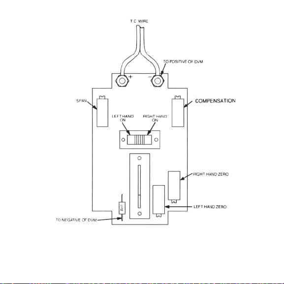
Figure 4-1. Calibration Hook-Up, Model CL-300
8
Page 15

Section 5 Specifications CL-300
Batteries: Two “AA” alkaline cells provide
Battery Indicator: LED light pulse at turn-on in either
Accuracy: ±0.1% of span ±1˚. For negative
Cold-junction Compensation: Built-in for specified thermocouple
Cold-junction Temperature
Effect: Within ±0.25 degrees at 75˚F (20˚C)
Operating Ambient
Temperature: -10˚ to +130˚F (-25˚ to +55˚C)
Ambient Temperature Effect: Zero included in cold-junction effect.
Storage Temperature Limits: -40˚ to +160˚F (-40˚ to +70˚C)
Output Impedance: Fixed, 50 ohms nominal
Dimensions: H: 4" (101 mm) x W: 2
Weight: 6 oz. (0.15 kg)
approximately one year of use
range
temperatures, add ±2˚.
type
±0.025 degrees/degree change in
ambient
Span: ±0.01% of span/degree
1
x D: 2 1/4" (57 mm)
/8" (54 mm)
9
Page 16
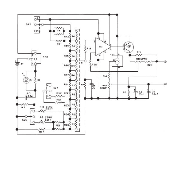
Schematic–OMEGA Model CL-300
10
Page 17

Table of Contents
Model CL-301 Portable RTD Simulator
Section Page
Section 1 Introduction. . . . . . . . . . . . . . . . . . . . . . . . . 12
1.1 Description. . . . . . . . . . . . . . . . . . . . . . . . . . . . . . . . . . . . . . . . 12
1.2 Features. . . . . . . . . . . . . . . . . . . . . . . . . . . . . . . . . . . . . . . . . . . 12
Section 2 Installation . . . . . . . . . . . . . . . . . . . . . . . . . 13
2.1 Unpacking . . . . . . . . . . . . . . . . . . . . . . . . . . . . . . . . . . . . . . . . 13
Section 3 Operation . . . . . . . . . . . . . . . . . . . . . . . . . . 14
3.1 Operating Instructions. . . . . . . . . . . . . . . . . . . . . . . . . . . . . . 14
Section 4 Service Information. . . . . . . . . . . . . . . . . . . 16
4.1 Maintenance. . . . . . . . . . . . . . . . . . . . . . . . . . . . . . . . . . . . . . . 16
4.2 Equipment Required for Calibration. . . . . . . . . . . . . . . . . . 16
4.3 Calibration Procedure . . . . . . . . . . . . . . . . . . . . . . . . . . . . . . 16
Section 5 Specifications . . . . . . . . . . . . . . . . . . . . . . . 19
11
Page 18

Section 1 Introduction
1.1 Description
The OMEGA®Model CL-301 Platinum RTD Simulator provides eleven
precise temperatures for inputs to transmitters, recorders, contr ollers,
alarms, data acquisition, and computer systems. Model CL-301 allows
2, 3, or 4-wire connections. Conformity to the particular RTD curve is in
accordance with the latest DIN 43760 standard.
Calibrations are available in both ˚F and ˚C and standard ranges are
listed in T able 1-1. Other ranges and curves are available as options.
Resolution is 25˚, 50˚, or 100˚, corresponding to the full scale output of
250˚, 500˚, and 1000˚ respectively.
Positive switch selection allows quick, easy settings for any output.
Calibrated accuracy is ±0.05% of span ±0.25˚.
1.2 Features
• Calibrate and T roubleshoot 2, 3, or 4-wire RTD systems
• Simulates 100 ohm RTD, alpha = .00385
* Choice of Output T erminal
• Eleven Precise Test Points
• Portable, No Battery or Power Required
• Simple to Use, Inexpensive to Own
12
Page 19
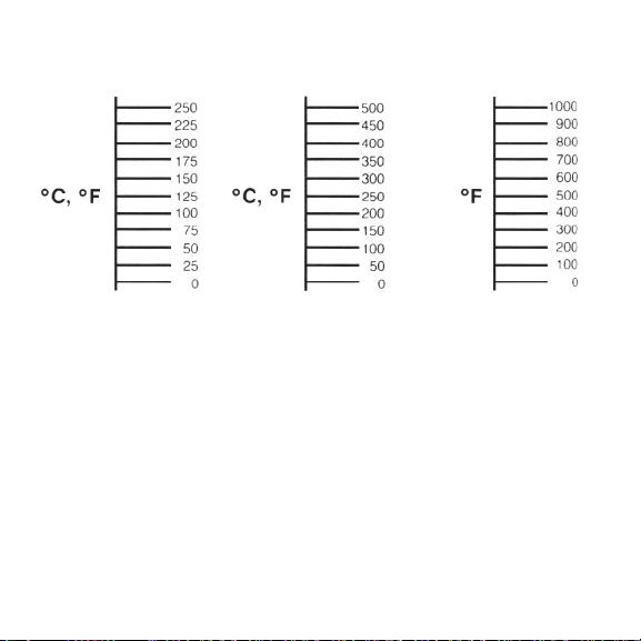
Model CL-301 Standard Ranges
Table 1-1
Section 2 Installation
2.1 Unpacking
Remove the Packing List to check off actual equipment received. If you
have any questions about the shipment, please call OMEGA’s
Customer Service Department.
Upon receipt of shipment, inspect the container for any signs of
damage in transit. Take particular note of any evidence of rough
handling in transit. Immediately report any damage to the shipping
agent.
13
Page 20

NOTE
The carrier will not honor any claims unless all shipping material
is saved for their examination. After examining and removing contents,
save packing material and carton in the event shipment is necessary.
Section 3 Operation
3.1 Operating Instructions
Select the particular OMEGAModel CL-301 for the desired
temperature scale (F or C), and appropriate temperature range. Then
choose the cable type (2, 3, or 4-wire) that is equivalent to the RTD
you are simulating . See Figure 3-1.
Connect the RTD Simulator leads to the input terminals of the
instrument or system to be tested. Typically the CL-301 might feed a
recording system, a controller, a datalogger , and a computer interface.
Set the temperature selection switch on the CL-301 to the desired
temperature. End point calibration temperatures of the instrument are
then selected on the CL-301 and any required adjustments are made.
Intermediate points on the CL-301 may then be selected to verify
instrument linearity or to check critical points.
14
Page 21
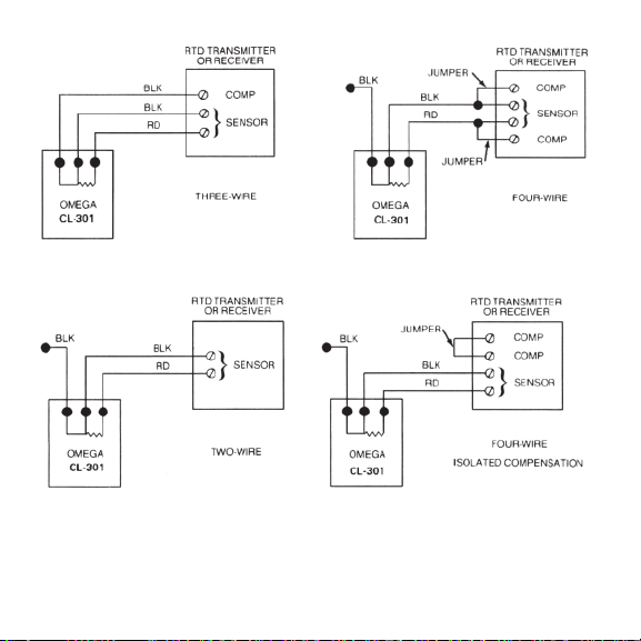
Figure 3-1. Connecting the RTD Simulator to Transmitter
or Receiver
15
Page 22

Section 4 Service Information
4.1 Maintenance
The OMEGA CL-301 RTD Simulator requires little servicing. Should
measurement inaccuracies be discovered, perform the adjustment and
calibration procedure to recalibrate the instrument.
4.2 Equipment Required for Calibration
Digital ohmeter, 0.025% accuracy with 4-wir e ohm connections
(OMEGA Model 881 or equivalent).
4.3 Calibration Procedure
Calibrate the instrument in the following manner:
1 Connect the unit to the meter in a 3-wire hookup.
2. Move the slide switch to the lowest temperature position (position
1) and adjust corresponding potentiometer (Pot 1, Figure 4-1)
according to the resistance value obtained form Table 4-1.
3. Move the switch to the next temperature position (2) and adjust
corresponding potentiometer (Pot 2).
4. Continue this procedure for all remaining temperature positions in
ascending order .
16
Page 23
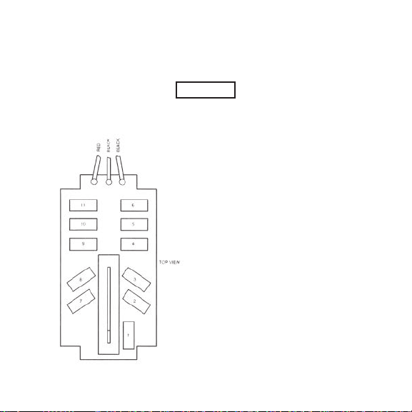
5. Upon completion, move the switch back to position 1. Check and
readjust potentiometer (Pot 1), if necessary. In increasing order,
check and readjust each position as necessary to obtain specified
accuracy.
CAUTION
Each time a position is adjusted, ALL higher number positions must be
rechecked.
Figure 4-1. Potentiometer
Adjustments, Model CL-301
17
Page 24

Table 4-1
Adjustment Values
Material and Nominal Resistance Alpha (α) R (100˚C)/R (0˚C)
Platinum (PT.)* 1.3850 (DIN Standard 43760)
100 OHM 1.3926 (U.S. Laboratory)
200 OHM 1.3889 (Canadian)
500 OHM 1.3911 (U.S. Industrial)
Nickel 1.6720
120 OHM
600 OHM
Nickel-Iron 1.5188
604 OHM
Copper 1.4274
9.035 OHM (10 OHMS at 25˚C)
234 OHM
421.2 OHM
1000 OHM
2000 OHM (at 70˚F)
*If not specified DIN standard cur ve 43760 will be supplied.
1.3902 (U.S. Industrial)
18
Page 25
Section 5 Specifications CL-301
Accuracy: ±0.05% of span ±0.25 degree
Operating Ambient
Temperature: -10˚ to +130˚F (-25˚ to +55˚C)
Ambient Temperature Effect: ±0.01% degree (% of span)
Storage Temperature Limits: -40˚ to +160˚F (-40˚ to +70˚C)
Dimensions: H: 4" (101 mm) x W: 2
x D: 2 1/2" (38 mm)
Weight: 3 oz. (0.12 kg)
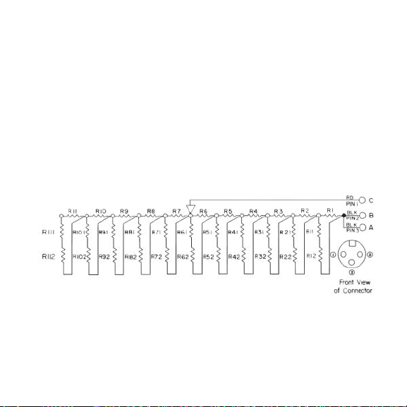
Schematic–OMEGA Model CL-301
19
1
/8" (54 mm)
Page 26

Table of Contents
Model CL-302 Portable Transmitter Simulator
Section Page
Section 1 Introduction. . . . . . . . . . . . . . . . . . . . . . . . . 21
1.1 Description. . . . . . . . . . . . . . . . . . . . . . . . . . . . . . . . . . . . . . . . 21
1.2 Features. . . . . . . . . . . . . . . . . . . . . . . . . . . . . . . . . . . . . . . . . . . 21
Section 2 Installation . . . . . . . . . . . . . . . . . . . . . . . . . 21
2.1 Unpacking . . . . . . . . . . . . . . . . . . . . . . . . . . . . . . . . . . . . . . . . 21
Section 3 Operation . . . . . . . . . . . . . . . . . . . . . . . . . . 22
3.1 Operating Instructions. . . . . . . . . . . . . . . . . . . . . . . . . . . . . . 22
Section 4 Service Information. . . . . . . . . . . . . . . . . . . 24
4.1 Maintenance. . . . . . . . . . . . . . . . . . . . . . . . . . . . . . . . . . . . . . . 24
4.2 Equipment Required for Calibration. . . . . . . . . . . . . . . . . . 24
4.3 Calibration Procedure . . . . . . . . . . . . . . . . . . . . . . . . . . . . . . 24
4.3.1 Calibration Hookup Procedure . . . . . . . . . . . . . . . . . . . . . . 24
4.3.2 Span and Zero Adjustment Procedures . . . . . . . . . . . . . . . 25
4.3.3 Linearity Test Protocol . . . . . . . . . . . . . . . . . . . . . . . . . . . . . . 25
Section 5 Specifications . . . . . . . . . . . . . . . . . . . . . . . 27
20
Page 27

Section 1 Introduction
1.1 Description
The OMEGA®Model CL-302 T ransmitter Simulator provides lab
accuracy for a wide range of settings. Instant availability of data is
assured; no internal batteries or line cords are ever needed. Latest
microcircuitry includes a precision refer ence, ultra-stable comparator,
and a high-gain power Darlington output. Switch settings of 0%, 25%,
50%, 75%, and 100% allow fast full range check out of the instrument to
be calibrated. Low minimum voltage drop enables other devices to
remain in the loop while the receiving device is being calibrated.
1.2 Features
• Calibrate or T est, 4-20 mASystems
• Simulates Loop Powered Transmitter
• Five Precise Test Points
• Portable, 0.1% Accuracy
• No Batteries of Power Required
Section 2 Installation
2.1 Unpacking
Remove the Packing List to check off actual equipment received. If you
have any questions about the shipment, please call OMEGA’s
Customer Service Department.
21
Page 28
Upon receipt of shipment, inspect the container for any signs of
damage in transit. T ake particular note of any evidence of rough
handling in transit. Immediately report any damage to the shipping
agent.
NOTE
The carrier will not honor any claims unless all shipping material
is saved for their examination. After examining and removing contents,
save packing material and carton in the event shipment is necessary.
Section 3 Operation
3.1 Operating Instructions
First disconnect the transmitter form the loop, leaving the power
source and receiver in place.
Connect the two clip leads of the Simulator to the positive (+) and the
negative (-) field connections of the receiver or controller (to be
checked or calibrated) in place of the field 2-wire transmitter. See
Figure 3-1. An LED indicates current flowing through the calibrator.
The selector switch is then positioned at the 0% point. Exactly 4 mA
will pass through the loop. At this time, the zero of the r eceiver is
adjusted. Move the switch to allow 100% to pass and make the
required full scale adjustment. When both span and zero are corr ect,
the 25%, 50% and 75% settings are used to check linearity. Selected
settings are accurate within ±0.1% of span.
22
Page 29
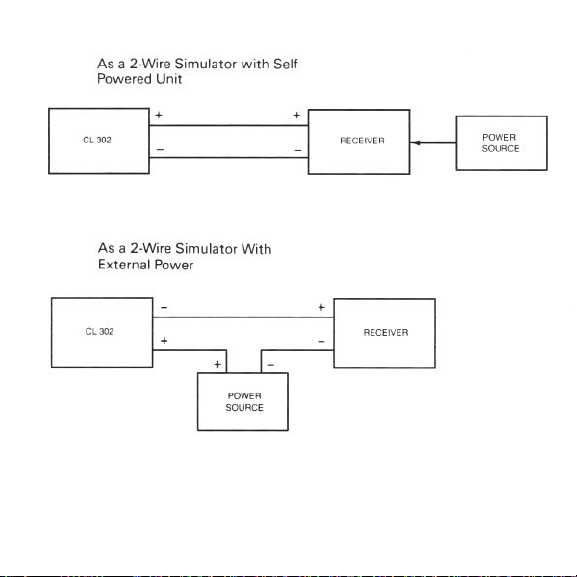
Figure 3-1. Alternative Hookup Methods
23
Page 30

Section 4 Service Information
4.1 Maintenance
The OMEGA CL-302 Transmitter Simulator is long-lasting and
requires little servicing. Should measurement inaccuracies be
discovered, perform the adjustment and calibration procedures,
specified below , to recalibrate the instrument.
4.2 Equipment Required for Calibration
Digital voltmeter,4 1/2digit, 0.05% (or better) accuracy with a
precision (±0.05%) 250-ohm resistor.
4.3 Calibration Procedure
Calibration requires a hookup protocol, span and zero adjustments,
and a linearity test.
4.3.1 Calibration Hookup Protocol
1 Set the calibrating meter to a range which covers the 1 to 5 V dc
spectrum with sufficient resolution.
2. Place the 24 to 30 V dc power supply in series with the 250 ohm
(±0.05%) resistor and the Simulator which is to be calibrated. The
meter will read 1 to 5 volts corresponding to 4-20 mAthrough the
resistor . See Figure 4-1. The LED on the Simulator should be lit,
indicating that the connections are correct and that the unit is
functioning..
24
Page 31

4.3.2 Span and Zero Adjustment Procedures
1 Set the switch on the Model CL-302 to the 209 mA (100%) position.
2. The span potentiometer is adjusted so that the meter reads 5.000
volts. See Figure 4-2.
3. The switch is now moved to position 4 mA (0%).
4. The zero potentiometer is adjusted until the meter reads 1.000
volts.
5. Check and readjust the span and the zero controls until they are
within ±0.1% accuracy (±0.02% typical).
4.3.3 Linearity Test Protocol
1 Move the switch to position 8 mA (25%). The meter should read
between 1.996 V and 2.004 V.
2. With the meter set at 12 mA (50%), the meter should read between
2.996 V and 3.004 V.
3. Setting the meter at 16 mA ((75%), the meter should read between
3.996 V and 3.004 V.
25
Page 32
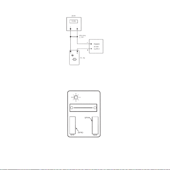
Figure 4-1. Calibration Check
Figure 4-2. Zero and Span Controls, Model CL-302
26
Page 33

Section 5 Specifications CL-302
Calibrated Accuracy: ±0.1% of span
Precise Switch Settings: 0, 25, 50, 75, 100% of full scale
Temperature Effect: ±0.01%/˚C
Loop Voltage Rating: Any between 6 and 45 volts
Voltage Drop: 6 V and 20 mA
Dimensions: H: 3
Weight: 3 oz. (85 grams)
equivalent to 4, 8, 12, 16, 20 mA
1
/4" (82 mm) x W: 2 1/8"
(54 mm) x D: 1 1/8" (29 mm)
27
Page 34
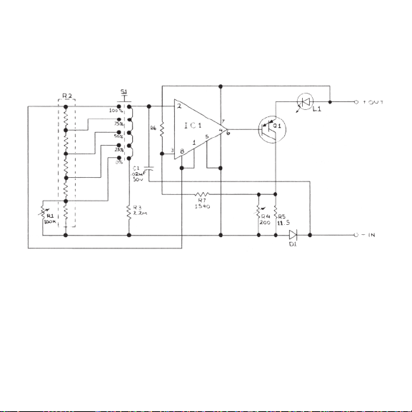
Schematic–OMEGA Model CL-302
28
Page 35

Table of Contents
Model CL-303 Portable mA Source/
2-Wire Simulator
Section Page
Section 1 Introduction. . . . . . . . . . . . . . . . . . . . . . . . . 30
1.1 Description. . . . . . . . . . . . . . . . . . . . . . . . . . . . . . . . . . . . . . . . 30
1.2 Features. . . . . . . . . . . . . . . . . . . . . . . . . . . . . . . . . . . . . . . . . . . 32
Section 2 Installation . . . . . . . . . . . . . . . . . . . . . . . . . 32
2.1 Unpacking . . . . . . . . . . . . . . . . . . . . . . . . . . . . . . . . . . . . . . . . 32
Section 3 Operation . . . . . . . . . . . . . . . . . . . . . . . . . . 33
3.1 Operating Instructions. . . . . . . . . . . . . . . . . . . . . . . . . . . . . . 33
3.1.1 Directions for 2-Wire Simulator Mode . . . . . . . . . . . . . . . . 33
3.1.2 Directions for Source Mode. . . . . . . . . . . . . . . . . . . . . . . . . . 34
Section 4 Service Information. . . . . . . . . . . . . . . . . . . 35
4.1 Maintenance. . . . . . . . . . . . . . . . . . . . . . . . . . . . . . . . . . . . . . . 35
4.2 Equipment Required for Calibration. . . . . . . . . . . . . . . . . . 35
4.3 Calibration Procedure . . . . . . . . . . . . . . . . . . . . . . . . . . . . . . 36
4.3.1 mAOutput, Source Mode Calibration . . . . . . . . . . . . . . . . 36
4.3.2 Span and Zero Adjustments . . . . . . . . . . . . . . . . . . . . . . . . . 36
4.3.2.1 2-Wire Simulator Mode Check . . . . . . . . . . . . . . . . . . . . . . . 37
Section 5 Specifications . . . . . . . . . . . . . . . . . . . . . . . 41
29
Page 36

Section 1 Introduction
1.1 Description
The dual function OMEGA®CL303 Simulator combines a selfcontained 4-20 mA source with a 2-wire Simulator in one pocketsized instrument.
Internal batteries are used in the source mode to provide continuously
adjustable 4-20 mA into any load from 0-800 ohms. An optional ac
adaptor allows full-time bench use.
The 2-wire Simulator mode utilizes external loop power to pass
precisely adjustable 4-20 mA. Loop power may vary from 6 to 45 V dc.
In addition to the 0.1% accurate digital dial adjustments, switch
selected signals are provided at 4.00 mA(00.0%) and 20.00 mA (100%)
for “quick check” zero and full scale settings in both modes (refer to
T able 1-1).
Small size is made possible through state-of-the-art design which
includes a precision reference, an ultra-stable amplifier, and high-gain
power Darlington output. Accuracy, stability and low power
consumption are combined through he use of the latest microcircuitry.
Continuous adjustability with memory lock assures fast, precise
settings of current trips, recorders, data loggers, controllers, computers,
and final control elements. Long life batteries allow complete
portability for checkout and calibration of all milliamp input devices.
30
Page 37

CL-303 Dial Settings and Output
Table 1-1
Dial Setting Output Current
% Milliamps
00.0 4.00
05.0 4.80
10.0 5.60
15.0 6.40
20.0 7.20
25.0 8.00
30.0 8.80
35.0 9.60
40.0 10.4
45.0 11.2
50.0 12.0
55.0 12.8
60.0 13.6
65.0 14.4
70.0 15.2
75.0 16.0
80.0 16.8
85.0 17.6
90.0 18.4
95.0 19.2
100.0 20.0
NOTE: Decimal point not shown on instrument’s dial.
31
Page 38

1.2 Features
• Calibrate or T est 4-20 mAdc Systems
• Precise 4-20 mAdc Source
• Simulates Loop Powered Transmitter
• Continuous 0 to 100% settings
• Quick Check 0% to 100% switch
Section 2 Installation
2.1 Unpacking
Remove the Packing List to check off actual equipment received.
If you have any questions about the shipment, please call OMEGA’s
Customer Service Department.
Upon receipt of shipment, inspect the container for any signs of
damage in transit. T ake particular note of any evidence of rough
handling in transit. Immediately report any damage to the shipping
agent.
NOTE
The carrier will not honor any claims unless all shipping material
is saved for their examination. After examining and removing contents,
save packing material and carton in the event shipment is necessary.
32
Page 39

Section 3 Operation
3.1 Operating Instructions
Outlined below is the operating protocol for the two modes of
operation.
3.1.1 Directions for 2-Wire Simulator Mode
Disconnect any existing 2-wire transmitter from the loop to be checked
or calibrated. (Only one of the two wires need be disconnected). Leave
the power source and the receiver in place.
Place the mode selector switch into the 2-wire position. Connect the red
clip lead of the Model CL-303 to the positive (+) terminal of the field
connections. Connect the black lead to the negative (-) terminal. See
Figure 3-1.
The LED will glow steadily when current flows. If no glow appears,
recheck all external connections. Internal batteries are not used in this
mode.
The 00.0% (4.00 mA) and 100% (20.00 mA) Dial adjustments are
selected with the right-hand switch. Fast zero and full scale checks can
be made by means of the 00.0% and the 100% positions. Athird quick
check position may be established by adjusting the digital dial to the
desired percent value and locking it in place. The continuous
adjustment dial reads directly in percent of the 4-20 mAsignal. For
example, a dial setting of 750 is 75% of span or 16mA. Complete the
adjustments and turn the instrument off.
33
Page 40
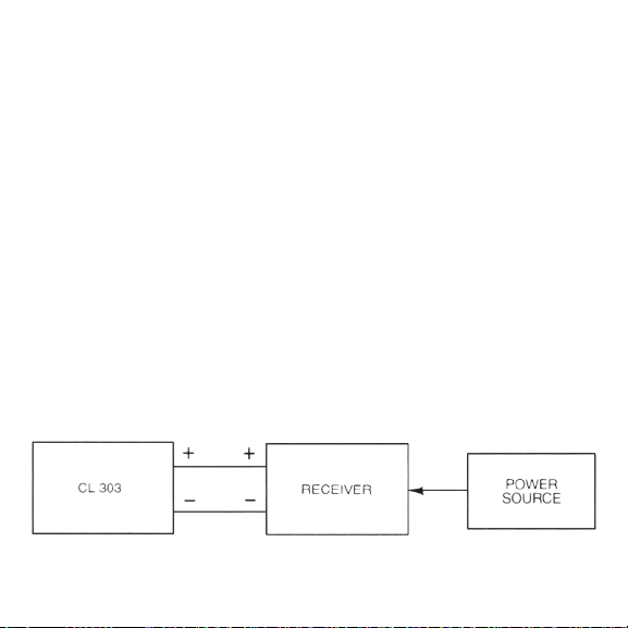
3.1.2 Directions for Source Mode
Disconnect any existing input wires from the device to be checked or
calibrated. Turn the mode selector switch (left-side) to the mAout
position. The LED will pulse brightly once if the battery voltage is
sufficient. If the LED does not pulse, turn it off and check the batteries.
Connect the red positive (+) lead to the positive input of the device to
be checked or calibrated. Connect the black negative (-) lead to the
negative terminal. See Figure 3-2. The LED will glow steadily when
current is flowing. If no glow appears, check the hookup and
connections.
The 00.0% (4.00 mA) and 100% (20.00 mA) D
selected with the right-hand switch. Fast zero and full scale checks can
be made by means of the 00.0% and the 100% positions. A third quick
check position may be established by adjusting the digital dial to the
desired percent value and locking it in place. The continuous
adjustment dial reads directly in percent of the 4-20 mA signal. For
example, a dial setting of 500 is 50% of span or 12mA. Complete the
adjustments and turn the instrument off. Reconnect any wires that
were removed for the check out.
ial adjustments are
Figure 3-1. As a 2-Wire Simulator with Self Powered Unit
34
Page 41
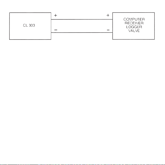
Figure 3-2. As a Milliamp Source
Section 4 Service Information
4.1 Maintenance
The CL-303 mASource/2-wire Simulator requires little servicing.
Should measurement inaccuracies be discovered, perform the
adjustment and calibration procedures to recalibrate the instrument.
4.2 Equipment Required for Calibration
Digital voltmeter, 4 1/2" digit, 0.05% or better accuracy, with a precision
(±0.5%) 250 ohm resistor. As a less accurate alternative, a dc millimeter
may be used directly–which eliminates the 250 ohm resistor.
35
Page 42

4.3 Calibration Procedure
Both the mA output and the span and zero adjustments must be
calibrated, as specified below .
4.3.1 mA Output, Source Mode Calibration
Proceed as follows:
1. Before any adjustments to the Model CL-303 are made, fresh
alkaline batteries MN1604, should be placed in the unit.
2. Switch the left-hand switch to position mA OUT while observing
the LED. The LED should flash once, indicating proper battery
voltage. If the LED does not flash, check each battery for proper
voltage and for correct connection.
3. Set the meter to a range which covers one to five V dc with
sufficient resolution.
4. Place the 250 ohm (±0.05%) resistor in series with the Model CL-303
output. The meter will read 1 to 5 volts corresponding to 4-20 mA
through the resistor. See Figure 4-1.
4.3.2 Span and Zero Adjustments
Make the necessary calibration adjustments as indicated below.
1. Set the left-hand switch to position mA OUT and the right-hand
switch to position 100%.
36
Page 43

2. The span potentiometer (Figure 4-2) should now be adjusted so
that the meter reads 5,000 volts.
3. The right-hand switch is now moved to the 00.0% position.
4. The zero potentiometer should now be adjusted so that the meter
reads 1.000 volts.
5. Check and readjust the span and zero controls until no further
adjustments are necessary.
6 Move the right-hand switch to the Dial position. The meter
should read between 1.996 V and 2.004 V when the dial is set at
25.0 (Note: decimal points are not shown on the dial). Other
readings are 2.996 V to 3.004 V at a setting of 50.0% and 3.98 V to
4.004 V at a setting of 75.0%. The dial has been mechanically set at
the factory and should need no adjustment under normal
operating conditions.
4.3.2.1 2-Wire Simulator Mode Check
To check the 2-wire Simulator of the CL-303:
1. Reconnect the test set-up to that shown in Figure 4-3.
2. Move the left-hand switch to the “2-wire” position.
3. Place a 24-30 V dc power source in series with the Model CL-303
and the 250 ohm resistor . The 100%, 00.0% and dial readings
should all be within ±0.1% F .S. ±1˚ of those found in the source
mode.
37
Page 44
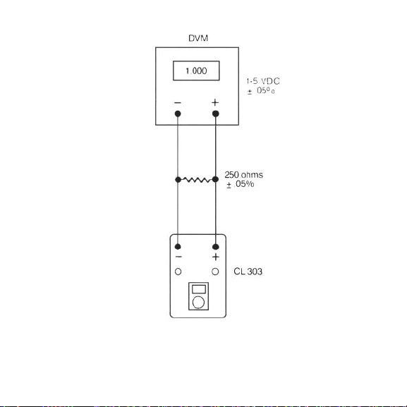
Figure 4-1. Measuring mA Output
38
Page 45
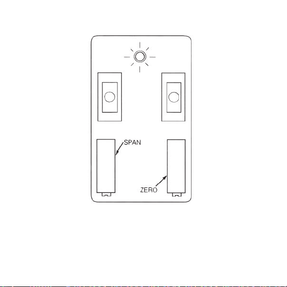
Figure 4-2. Adjustment of Span Potentiometer, Model CL-303
39
Page 46
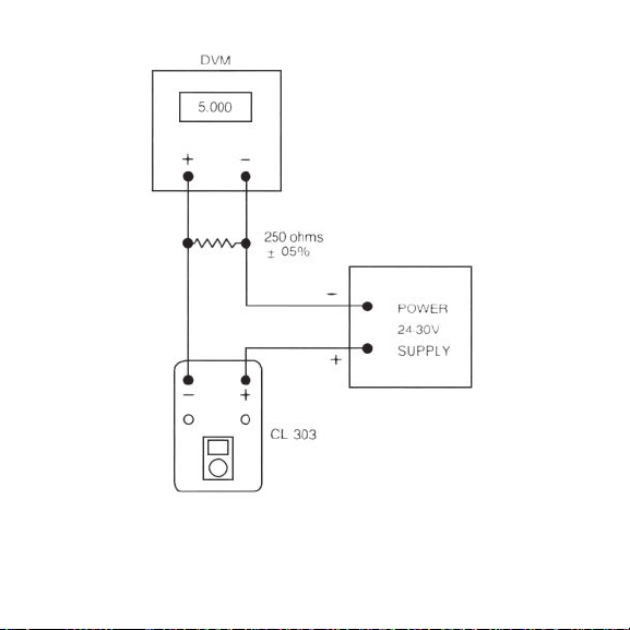
Figure 4-3. 2-Wire Simulator Hookup
40
Page 47

Section 5 Specifications CL-303
Internal Batteries: Three 9 Volt Alkaline, MN1604 or
Battery Life: Source; 25-hours at 20 mAcontinuous
Battery Status Indicator: LED pulse at turn-on, in source mode
Calibrated Accuracy: ±0.1%
Resolution: 0.02%
Temperature Effect: 0.01%/˚C
Output Drive Capability: 1200 ohms with fresh batteries, or
Power Supply Effect: 0.005%/Volt
Operating Ambient
Temperature: -10˚ to +140˚ F (-25 to +60˚C)
Storage Temperature Limits: -40˚ to +160˚F (-40˚ to +70˚C). Remove
Warm-up Time: 2-seconds to rated accuracy
Dimensions: H: 4" (101 mm) x W: 2
Weight: 11 oz. (0.3 kg)
equivalent
output, 2-wire Simulator infinite
with optional ac adaptor; 800 ohms at
battery low limit
batteries if stored for extended
period.
1
x D: 2 1/4" (57 mm)
/8" (54 mm)
41
Page 48
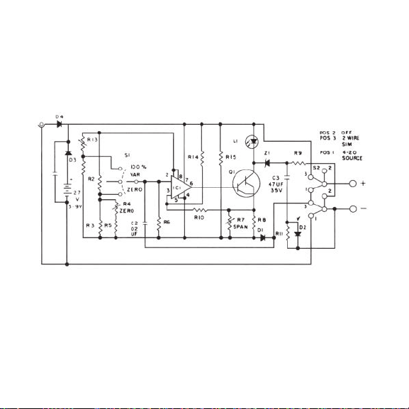
Schematic–OMEGA Model CL-303
42
Page 49

Notes
Page 50

Notes
Page 51

OMEGA ENGINEERING, INC. warrants this unit to be free of defects in
materials and workmanshipfor a period of 13 months from date of
puchase. OMEGA’s WARRANTY adds an additional one (1) month grace
period to the normal one (1) year product warranty to cover handling and shipping time.
This ensures that OMEGA’s customers receive maximum coverage on each product.
If the unit malfunctions, it must be returned to the factory for evaluation. OMEGA’s Customer
Service Department will issue an Authorized Return (AR) number immediately upon phone
or written request. Upon examination by OMEGA, if the unit is found to be defective, it
will be repaired or replaced at no charge. OMEGA’s WARRANTY does not apply to defects
resulting from any action of the purchaser, including but not limited to mishandling, improper
interfacing, operation outside of design limits, improper repair, or unauthorized modification.
This WARRANTY is VOID if the unit shows evidence of having been tampered with or shows
evidence of having been damaged as a result of excessive corrosion; or current, heat, moisture
or vibration; improper specification; misapplication; misuse or other operating conditions
outside of OMEGA’s control. Components in which wear is not warranted, include but are not
limited to contact points, fuses, and triacs.
OMEGA is pleased to offer suggestions on the use of its various products. However,
OMEGA neither assumes responsibility for any omissions or errors nor assumes
liability for any damages that result from the use of its products in accordance
with information provided by OMEGA, either verbal or written. OMEGA warrants
only that the parts manufactured by the company will be as specified and free of
defects. OMEGA MAKES NO OTHER WARRANTIES OR REPRESENTATIONS OF ANY
KIND WHATSOEVER, EXPRESSED OR IMPLIED, EXCEPT THAT OF TITLE, AND ALL
IMPLIED WARRANTIES INCLUDING ANY WARRANTY OF MERCHANTABILITY AND
FITNESS FOR A PARTICULAR PURPOSE ARE HEREBY DISCLAIMED. LIMITATION
OF LIABILITY: The remedies of purchaser set forth herein are exclusive, and the
total liability of OMEGA with respect to this order, whether based on contract,
warranty, negligence, indemnification, strict liability or otherwise, shall not exceed
the purchase price of the component upon which liability is based. In no event shall
OMEGA be liable for consequential, incidental or special damages.
CONDITIONS: Equipment sold by OMEGA is not intended to be used, nor shall it be used:
(1) as a “Basic Component” under 10 CFR 21 (NRC), used in or with any nuclear installation
or activity; or (2) in medical applications or used on humans. Should any Product(s) be
used in or with any nuclear installation or activity, medical application, used on humans, or
misused in any way, OMEGA assumes no responsibility as set forth in our basic WARRANTY/
DISCLAIMER language, and, additionally, purchaser will indemnify OMEGA and hold OMEGA
harmless from any liability or damage whatsoever arising out of the use of the Product(s) in
such a manner.
WARRANTY/DISCLAIMER
Page 52

Where Do I Find Everything I Need for
Process Measurement and Control?
OMEGA…Of Course!
Shop online at omega.com
TEMPERATURE
MU
Thermocouple, RTD & Thermistor Probes,
Connectors, Panels & Assemblies
MU
Wire: Thermocouple, RTD & Thermistor
MU
Calibrators & Ice Point References
MU
Recorders, Controllers & Process Monitors
MU
Infrared Pyrometers
PRESSURE, STRAIN
AND FORCE
MU
Transducers & Strain Gages
MU
Load Cells & Pressure Gages
MU
Displacement Transducers
MU
Instrumentation & Accessories
FLOW/LEVEL
MU
Rotameters, Gas Mass Flowmeters
& Flow Computers
MU
Air Velocity Indicators
MU
Turbine/Paddlewheel Systems
MU
Totalizers & Batch Controllers
pH/CONDUCTIVITY
MU
pH Electrodes, Testers & Accessories
MU
Benchtop/Laboratory Meters
MU
Controllers, Calibrators, Simulators
& Pumps
MU
Industrial pH & Conductivity Equipment
DATA ACQUISITION
MU
Data Acquisition &
Engineering Software
MU
Communications-Based
Acquisition Systems
MU
Plug-in Cards for Apple, IBM
& Compatibles
MU
Data Logging Systems
MU
Recorders, Printers & Plotters
HEATERS
MU
Heating Cable
MU
Cartridge & Strip Heaters
MU
Immersion & Band Heaters
MU
Flexible Heaters
MU
Laboratory Heaters
ENVIRONMENTAL
MONITORING AND CONTROL
MU
Metering & Control Instrumentation
MU
Refractometers
MU
Pumps & Tubing
MU
Air, Soil & Water Monitors
MU
Industrial Water & Wastewater
Treatment
MU
pH, Conductivity & Dissolved
Oxygen Instruments
SM
M0144/0116
 Loading...