

Page 1
Extended Warranty
Program
SM
MADE IN
User’s Guide
®
Shop online at
omega.com
e-mail: [email protected]
®
For latest product manuals:
omegamanual.info
CL1600-120VAC
CL1600-240VAC
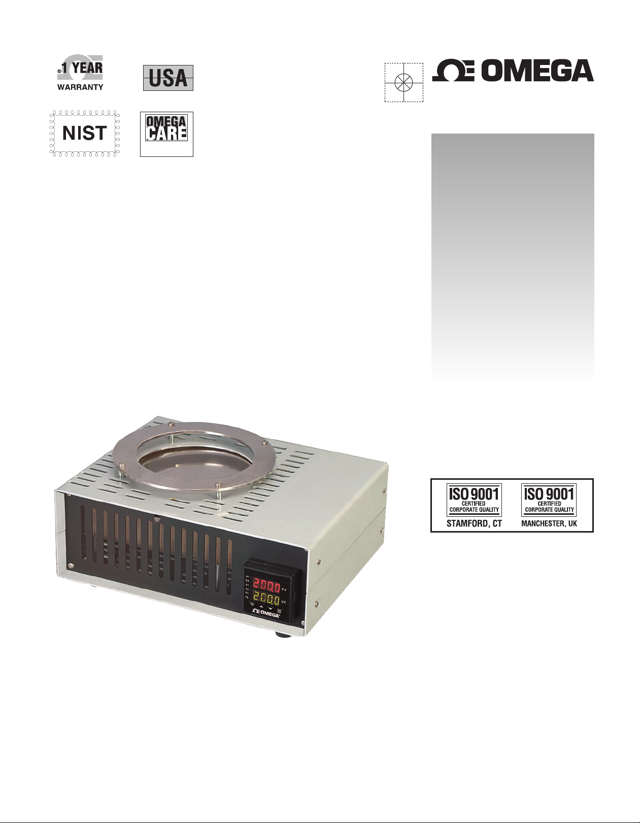
Surface Probe Tester
Page 2

OMEGAnet®Online Service Internet e-mail
®
omega.com [email protected]
Servicing North America:
U.S.A.: Omega Engineering, Inc., One Omega Drive, P.O. Box 4047
ISO 9001 Certified Stamford, CT 06907-0047 USA
Canada: 976 Bergar
Laval (Quebec), H7L 5A1 Canada
Toll-Free: 1-800-826-6342 TEL: (514) 856-6928
FAX: (514) 856-6886 e-mail: [email protected]
For immediate technical or application assistance:
U.S.A. and Canada: Sales Service: 1-800-826-6342/1-800-TC-OMEGA
Customer Service: 1-800-622-2378/1-800-622-BEST
Engineering Service: 1-800-872-9436/1-800-USA-WHEN
Mexico/ En Español: 001 (203) 359-7803 FAX: 001 (203) 359-7807
Latin America: [email protected] e-mail: [email protected]
®
®
®
Servicing Europe:
Benelux: Managed by the United Kingdom Office
Czech Republic: Frystatska 184
733 01 Karviná, Czech Republic
Toll-Free: 0800-1-66342 TEL: +420-59-6311899
FAX: +420-59-6311114 e-mail: [email protected]
France: Managed by the United Kingdom Office
Toll-Free: 0800 466 342 TEL: +33 (0) 161 37 29 00
FAX: +33 (0) 130 57 54 27 e-mail: [email protected]
Germany/ Austria: Daimlerstrasse 26
D-75392 Deckenpfronn, Germany
Toll-Free: 0800 6397678 TEL: +49 (0) 7056 9398-0
FAX: +49 (0) 7056 9398-29 e-mail: [email protected]
United Kingdom: OMEGA Engineering Ltd.
ISO 9001 Certified One Omega Drive, River Bend Technology Centre, Northbank
Irlam, Manchester M44 5BD United Kingdom
Toll-Free: 0800-488-488 TEL: +44 (0) 161 777-6611
FAX: +44 (0) 161 777-6622 e-mail: [email protected]
It is the policy of OMEGA Engineering, Inc. to comply with all worldwide safety and EMC/EMI
regulations that apply. OMEGA is constantly pursuing certification of its products to the European New
Approach Directives. OMEGA will add the CE mark to every appropriate device upon certification.
The information contained in this document is believed to be correct, but OMEGA accepts no liability for any
errors it contains, and reserves the right to alter specifications without notice.
WARNING: These products are not designed for use in, and should not be used for, human applications.
Page 3

Table of Contents
Section ........................................................................... Page
Section 1 Introduction .................................................................................. 1-1
Section 2 Installation .................................................................................... 2-1
Section 3 Operation ...................................................................................... 3-1
Table of
CL1600 Surface Probe Tester
Contents
1.1 Precautions ............................................................................. 1-1
1.2 Safety Warnings and IEC Symbols ...................................... 1-2
1.3 Statement on CE Marking .................................................... 1-2
1.4 General Description ............................................................... 1-2
2.1 Unpacking and Inspection ....................................................2-1
2.2 Mounting ................................................................................ 2-1
2.3 Ambient Temperature ........................................................... 2-1
2.4 Power Connection ................................................................. 2-2
2.5 Installing the CL1600 Programmer Software .................... 2-2
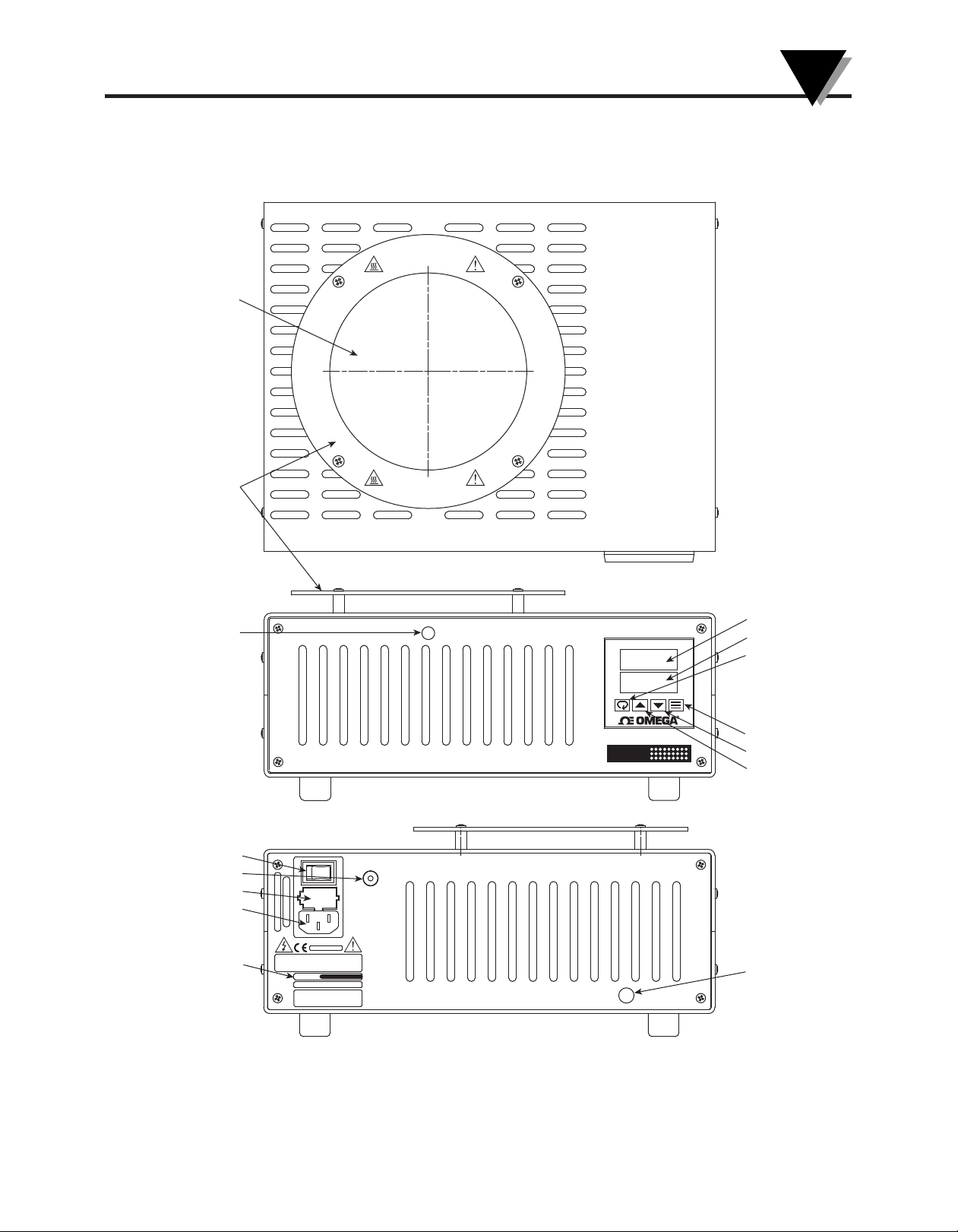
3.1 Front Panel Controls and Indicators ................................... 3-1
3.2 Changing the Temperature Setpoint ................................... 3-3
3.3 Heat-Up/Cool-Down Cycle Time Graphs ......................... 3-4
Section 4 RS232 Communication ................................................................ 4-1
Section 5 Maintenance ................................................................................. 5-1
5.1 Calibration .............................................................................. 5-1
5.2 Cleaning .................................................................................. 5-1
5.2.1 Main Body ...................................................................... 5-1
5.2.2 Target Plate .................................................................... 5-1
5.3 Fuse Replacement .................................................................. 5-1
Section 6 Troubleshooting Guide ............................................................... 6-1
Section 7 Glossary of Terms Used in This Manual .................................. 7-1
Section 8 Specifications ................................................................................ 8-1
i
Page 4

List of
Figures
CL1600 Surface Probe Tester
List of Figures
Figure Description: .......................................................... Page
1. I.E.C. Symbols ........................................................................................... 1-2
2. Main Screen ............................................................................................... 2-2
3. Setting Screen ............................................................................................ 2-3
4. Front Panel Controls and Indicators ...................................................... 3-1
5. Heat Up/Cool Down Transition Time Table ........................................ 3-4
6. Pinout For 9-Pin PC Series ...................................................................... 4-1
ii
Page 5

Section 1 - Introduction
The CL1600 Surface Probe Tester is designed for ease of use and reliability
whenever you have a need to test, check or confirm a reading from a surface
probe under a set temperature.
It is important that you read this manual completely and follow all safety
precautions before operating this instrument.
1.1 Precautions
To avoid personal injury, please follow all safety precautions and operating
instructions outlined in this section.
• Caution! Do not touch the hot plate or its surrounding components at any
time; the temperature on the hot plate is the same as the temperature indicated
on the controller display. Please be careful.
• The CL1600 can operate at very high temperatures, when testing and handling
surface sensors, they too will get very hot at the tip end, so be sure to have a heat
resistant plate to place the sensors after testing and to allow them to cool down.
• Never turn the power off when the hot plate is set to temperatures higher than
100 degrees C. Damage to the electronic controller or to the heater could occur.
• Never leave your tester unattended when in use.
• Keep out of children reach.
• Never permanently place or attach any object within 6 inches of the plate.
• Do not operate in explosive environments.
• Never operate this unit with a power cord other than the one provided with
this system.
• This instrument is intended for indoor use only.
• On initial use, or if this unit hasn’t been power for a period of 10 days, it is
recommended to turn the unit on and allow to run at 50 degrees C for 1 hour,
before using at higher settings.
• Components and heater lifetime can be shortened by continuous high
temperature use.
• Never place any foreign materials on the surface of the hot plate, fluids can
leak into the electronic cabinet and into the heater assembly causing risk of
injury and permanent damage to the tester.
• In the event this instrument blows a fuse, it could be due to a power surge or a
component failure. Replace the fuses once, and then re-power the unit. If the
fuses blow again, please contact Omega Engineering Customer Service at
1-800-622-2378 or 203-359-1660. We can also be reached on the Internet at
www.omega.com, e-mail: [email protected]
• Always replace fuses with one of the same rating, voltage and type. For safety
reasons; never replace a fuse with one of higher voltage value.
• The CL1600 Probe Tester was designed to be a precision instrument with
durability, trouble free and ease of operation as our main goals; as such, this
unit should not be operated in dirty, dusty, wet or oily environments.
Introduction
1
1-1
Page 6
1
Introduction
There are no user serviceable parts inside your unit. Attempting to repair or service
your unit may void your warranty.
1.2 Safety Warnings and IEC Symbols
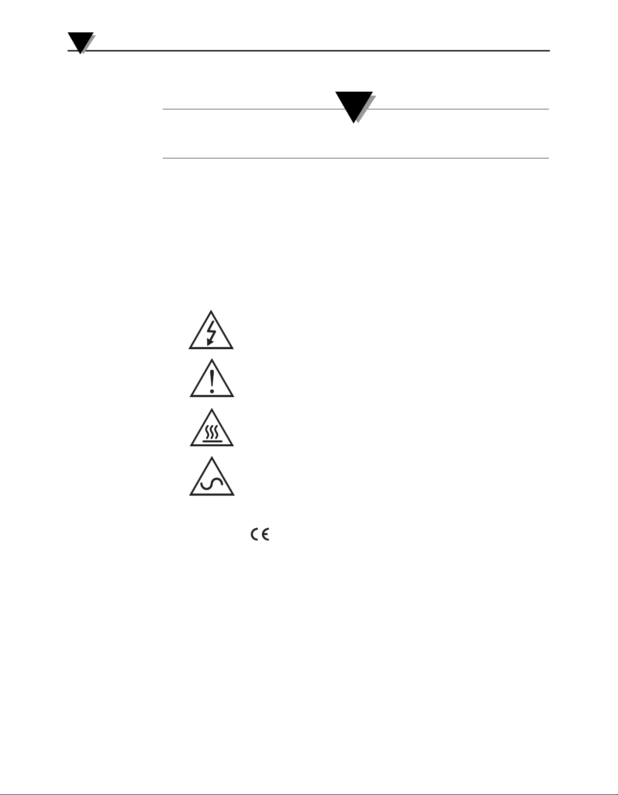
This device is marked with international safety and hazard symbols in
accordance with IEC 1010. It is important to read and follow all precautions and
instructions in this manual before operating or commissioning this device as it
contains important information relating to safety and EMC. Failure to follow all
safety precautions may result in injury and or damage to your tester. Use of this
device in a manner not specified by the manufacturer may impair protection
provided within the unit.
IEC symbols Description
NOTE:
Figure 1. IEC Symbols
1.3 Statement on Marking
It is the policy of OMEGA®to comply with all world-wide safety and EMI/EMC
regulations that apply. OMEGA is constantly pursuing certification of its
products to the European New Approach Directives. OMEGA will add the CE
mark to every appropriate device upon certification.
Caution, risk of electric shock
Caution, refer to accompanying
documents
Caution, hot surface
230 Vac @ 50 Hz (European Models)
115 Vac @ 60 Hz (Domestic Models)
1-2
1.4 General Description
Omega's CL1600 Surface Probe Tester is a system designed to check and verifly
surface probe readings across a wide range in temperatures, 25 to 450°C (77 to
842°F). The CL1600 allows periodic in-house testing and provides preventive
maintenance for all your surface sensors.
A large diameter, mirror like, high grade Aluminum alloy Hotplate design, allows
the most stability while maintaining quick, uniform heat-up on the entire system.
Page 7

Section 2 - Installation
2.1 Unpacking
Remove the packing list and verify that you have received all your equipment. If
you have any questions about the shipment, please call our Customer Service
Department at 1-800-622-2378 or 203-359-1660. We can also be reached on the
Internet at omega.com e-mail: [email protected]
When you receive the shipment, inspect the container and equipment for any
signs of damage. Note any evidence of rough handling in transit. Immediately
report any damage to the shipping agent.
The carrier will not honor any damage claims unless all shipping material is saved
for inspection. After examining and removing contents, save packing material and
carton in the event reshipment is necessary.
NOTE:
:
Installation
2
The following items are supplied in the box:
• CL1600 Surface Probe Tester (1)
• User’s Manual (1)
• Calibration Certificate (1)
• Power Cord (1)
• RS232 Communications Cable (1)
• User Interface Software CD (1)
2.2 Mounting
Place this unit on a bench or table top in horizontal position. To operate, be sure
to stay away from constantly open and close doors, air conditioning vents,
adjacent computer fans, room air moving fans, open windows, etc.
2.3 Ambient Temperature
The CL1600 Probe Tester can generate any temperature within the specified
temperature range when operated at ambient temperatures of 5 to 35°C (41 to
95°F).
2-1
Page 8
2
1
3
4
5
2
Installation
2.4 Main Power Connection
Use provided power cord.
NOTE:
:
All electrical connections and wiring should be performed by suitable trained
personnel only.
2.5 Installing the CL1600 Programmer Software
Overview
The CL1600 Surface Probe Tester ships from the factory with a copy of the
Omega Programmer software.
This is an easy to use software package, especially written for the CL1600. Only
one instrument can run this software in one computer at a time.
Program Installation
It is advisable to have your IT Department install this software into your
computer. Always back-up your system before attempting to install this or any
other software package into your computer.
Assuming you have backed up your computer files, run the install program.
This program will run trouble free with Windows
Figure 2. Main Screen
Figure 3. Setting Screen
®
95, 98, ME, NT, 2000 or XP.
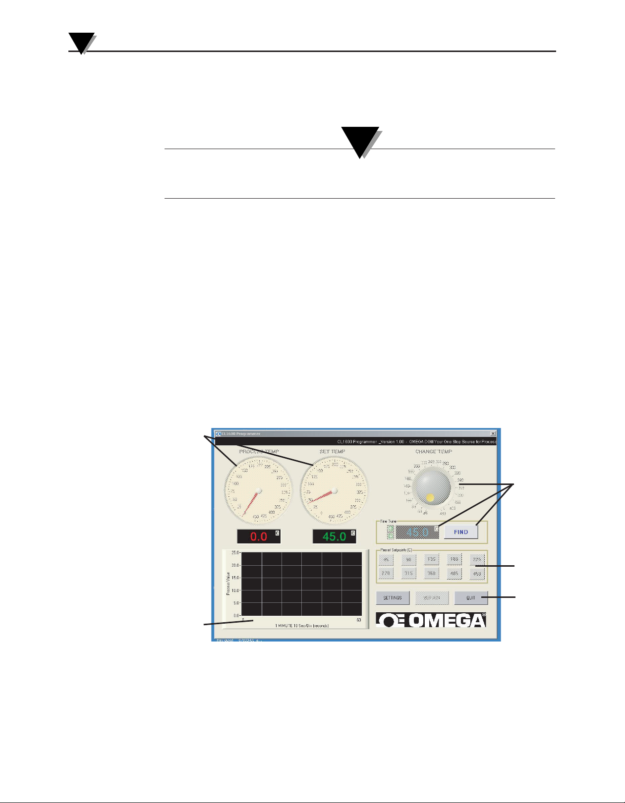
Figure 2. Main Screen
2-2
Page 9
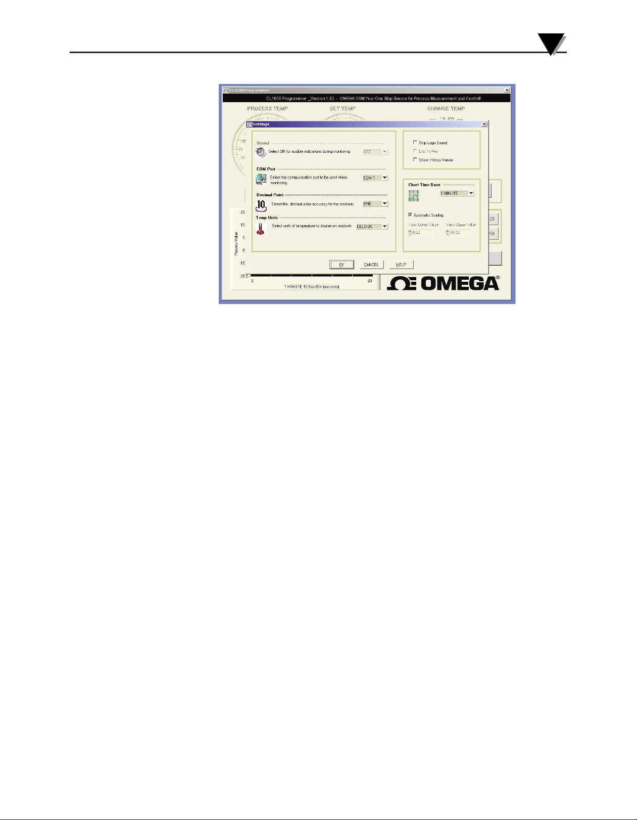
Figure 3. Setting Screen
Installation
2
On your desktop, double click the CL1600 programmer icon. This will open a
window and the Omega Logo (see figure 2) appears for a few seconds, then the
main screen opens.
1. On the main screen top left there are two analog gages and two digital display
windows below, one is red to indicate process temperature, the other is green
to indicate set point temperature.
2. Below, there is a graph which tracks the set point and process values.
The set point and process values are on the vertical axis, while the capture
duration time is displayed along the horizontal axis.
3. On the top right the change temperature wheel will allow rough temperature
setting between 45 to 450°C.
Below it there is a fine tune up and down arrow that allows for fine tune
settings in increments of 0.1 degrees.
To the right there is the FIND button. Pressing this button will start tracking
the set temperature on the controller.
4. The CL1600 programmer software includes 10 preset temperature settings
ranging from 45 to 450°C.
5. SETTINGS: Pressing this button will bring a second screen into view (see
figure 3).
SOUND: Will allow audible indications while monitoring.
Selections: ON, OFF
Default: OFF
COM Port: Selects the communication port to be used while
monitoring.
Selections are: COM 1, COM 2, COM 3 or COM 4.
Default: COM1
DECIMAL POINT: Selects the decimal point accuracy for the readouts.
Selections: ONE, NONE
Default: ONE
2-3
Page 10

2
Installation
TEMPERATURE UNITS: Selects units of temperature to display on
readouts.
Selections: CELSIUS, FAHRENHEIT
Default: CELSIUS
SKIP LOGO INTRODUCTION: Selecting this box will cancel the logo
introduction when the program is activated from your desktop.
LOG TO FILE: Selecting this box will allow data login
This command is inactive at this time.
CHART TIME BASE: Allows user to set the horizontal time graph
display
Selections are: 1 minute, 10 minutes and 1 hour
AUTOMATIC SCALING: Selecting this box will pre-select a vertical
scale which varies according to temperature
setting.
Un-selecting this box, will allow user to set up values to zoomin closer to the desired temperature range.
2-4
Page 11
CL1600
SURFACE PROBE
CALIBRATOR
MADE IN U.S.A.
90-250VAC 50/60 Hz, 925W
FUSE 2 EA: F 5A 250V
RS232
MODEL NO:
SERIAL NO:
OMEGA ENGINEERING INC.
STAMFORD, CT. 06907-0047
1-800-826-6342
www.omega.com
CL1600
CAUTION: FOR CONTINUED PROTECTION AGAINST
THE RISK OF FIRE REPLACE WITH ONLY THE SAME
TYPE, RATING AND SIZE OF FUSE. DISCONNECT
POWER FROM SOURCE BEFORE CHANGING FUSE.
O l
CAUTI ON!
HOT SURFACE
CAUTI ON!
HOT SURFACE
SURFAC E
PLAT E
PROCESS TEMP.
SETPOINT TEMP.
PARAMETER
ACCESS KEY
RAISE KEY
RESET
LOWER KEY
MODE KEY
POWER SWITCH
RS232 PORT
FUSE BOX
AC POWER
INPUT
MODEL/SERIAL
NUMBERS
SAFETY WARNING
TOP VIEW
FRONT VIEW
REAR VIEW
HEAT
SHIELD
REFERENCE
PROBE
ENTRY
PROBE NOT
SUPPLIED
Section 3 - Operation
3.1 Front Panel Controls and Indicators
Operation
3
Figure 4. Front Panel Controls and Indicators
3-1
Page 12

3
Operation
NOTE:
:
P.I.D. Control:
Proportional, integral, derivative control ( P.I.D.) is a temperature control algorithm
used in high-end temperature controllers. The controller causes the process to attain
the desired temperature by turning the process on or off. The process may be a
heater or refrigerator. As the process temperature approaches the setpoint
temperature the hot or cold process will be pulsed to reduce the corrective measures
and minimize overshooting. The controller provides a visual representation of the
process status through LED indicators. An indicator may be lit continuously, blink or
shut off entirely to indicate that the process is on, being pulsed, or off, respectively.
Parameter/ Access Key: This key is inactive.
Press to scroll through menu parameters
Raise Key:
Use to increase values (hold for fast-step progression).
Lower Key:
Use to decrease values (hold for fast-step progression).
Mode Key: This key is inactive.
Press to save settings and exit a menu level.
Process Temperature:
This field displays the current temperature of the target plate. (red display)
Setpoint Temperature:
The field displays the desired target temperature. Once the target plate reaches
this desired temperature, both displays will read the same value. (green display)
3-2
Page 13

AC Power Input:
The customer connects the power cord to the AC Power Input. As a safety
precaution, the power cord cannot be connected if the fuse compartment is open.
Refer to Section 5.3 for information on fuse replacement.
Reference Probe Port:
The reference probe port enables the user to monitor the target plate temperature
with an external instrument.
Serial Port:
The female phone jack port allows the customer to make RS232 interface with
the CL1600. A detailed description of this port is described in Section 4.
3.2 Changing the Temperature Setpoint
The internal parameters in the microprocessor have been set to be functional
between 25 and 450°C (77 to 842°F).
Operation
3
Manual Temperature Change
To change the temperature set point to any value within the allowable range, use
the up or down arrow keys as needed, holding the corresponding key down will
allow fast-step progression.
Automated Temperature Change
The CL1600 includes a user interface computer program, which can be accessed
and activated through the RS232 port. For a complete description of included
features, please turn to section 2-5.
3-3
Page 14

2.0 min. 4.0 min. 2.0 min. 8.0 min. 11.0 min.
50°C 100°C 200°C 300°C 400°C 450°C
25°C
FROM TO
16.0 min.
3
Operation
3
3.3 Heat-Up/Cool-Down Cycle Transition Times
The following table shows the amount of time required to change the target plate
temperature from one setpoint to another. The starting temperature is shown
along the left side. The final temperature is shown along the top. All transition
times are approximate.
Heat Up Transition Time
Figure 5. Heat Up/ Cool Down Transition Time Table
Cool Down Transition Time
The CL1600 will take 90 minutes to cool down from 450°C. Be sure the unit has
cooled down and it is safe to touch before handling the unit.
3-4
Page 15
Section 4 - RS232 Communication
TO: COMPUTER SERIAL PORT
TO: INSTRUMENT
1234
TX RX GND
TXRXGND
5
6789
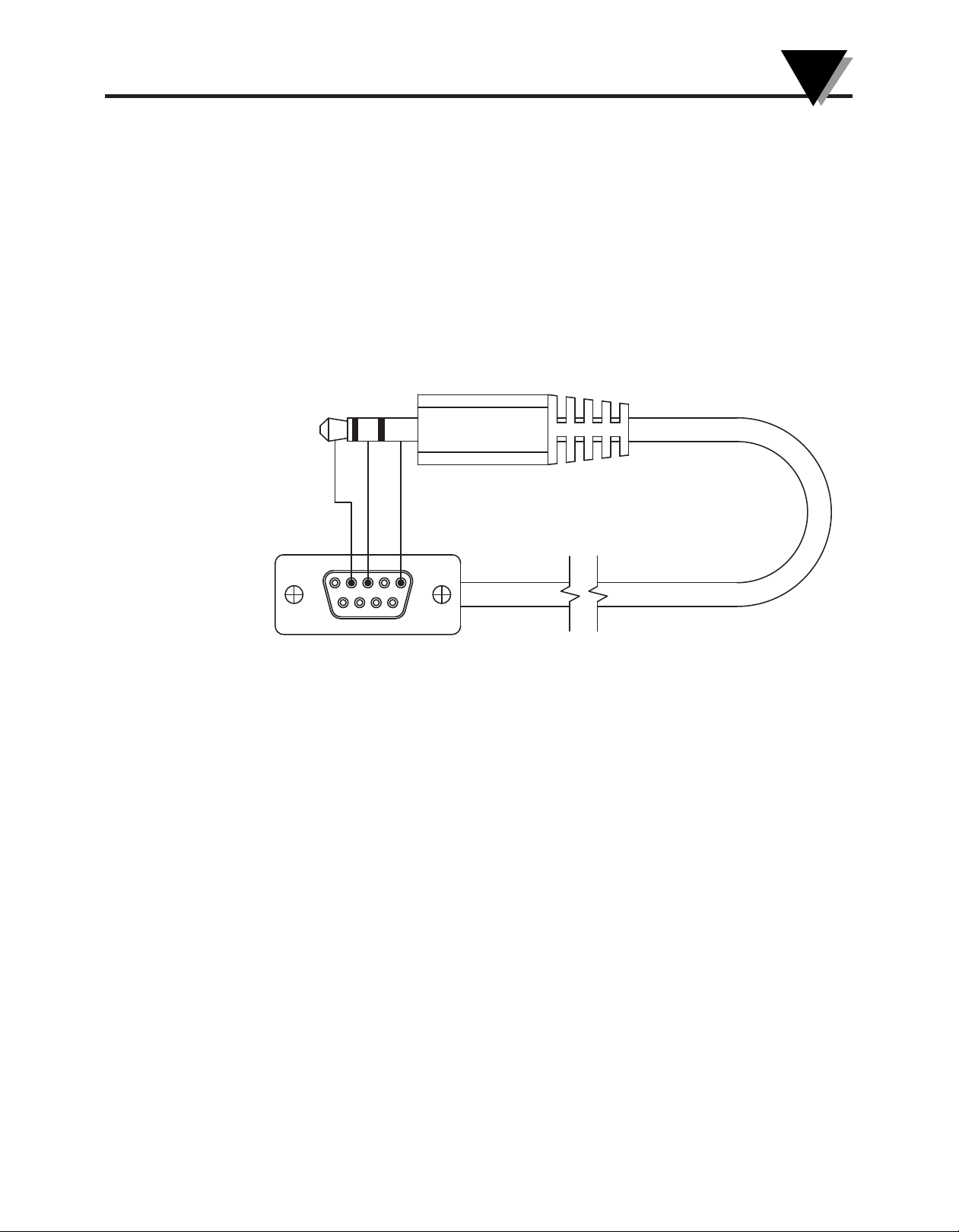
The RS232 communications port allows bi-directional data transfer via a three
conductor cable consisting of signal ground, receive input, and transmit output.
It is recommended that less than fifty feet of cable be used between the computer
and this instrument.* Note that multiple instruments cannot be tied to the same
port in this configuration. The RS232 port is optically isolated to eliminate
ground loop problems.
Below is a pinout diagram for the serial port of the CL1600 as well as the pinout
for a 9-pin PC serial port. The cable should be attached only when the computer
and CL1600 are off.
RS232 Communication
4
Figure 6. Pinout for a 9-pin PC Serial Port
4-1
Page 16

5
Maintenance
Section 5 - Maintenance
5.1 Calibration
This unit has been fine tuned at the factory and calibrated to give optimum
performance of its full temperature range. It is recommended that the unit be
returned annually
for re-calibration. Please call our Customer Service Department at 1-800-622-2378
or 203-359-1660.
5.2 Cleaning
Remove all electrical connections and power before attempting any cleaning.
5.2.1 Main Body
CAUTION:
:
Only a damp soft rag with a mild cleaning solution should be used to clean the
main body of this unit.
5.2.2 Target Plate
Do not attempt to clean the target plate. The target plate has a special coating
applied and cleaning may change the performance of your unit.
5.3 Fuse Replacement
Disconnect all power from source before attempting fuse replacement.
For continued protection against the risk of fire replace with only the same size, type
and rating fuse indicated here and on the rear panel of your unit.
WARNING:
:
CAUTION:
:
5-1
Model Fuse
For Model CL1600-120V use 2 ea. 250 VAC, F3.15A (Fast Acting 3.15 amps)
UL/CSA Approved (5 mm dia x 20 mm long)
For Model CL1600-240V use 2 ea. 250 VAC, F5A (Fast Acting 5 Amps)
UL/CSA Approved (5 mm dia x 20 mm long)
Page 17

Section 6 - Troubleshooting Guide
Problem Solution
1. Unit will not turn on. a. Check all electrical connections.
2. Unit turns on but the target a. Check that you have entered a setpoint
plate will not get hot. above the ambient temperature.
3. Controller display shows a. Unit requires service, contact our
“Error” and the target plate customer service department.
will not get hot or cold.
Troubleshooting Guide
b. Check rear panel fuses.
c. Unit requires service, contact our
customer service department.
b. Verify that the controller is set to its
factory default settings.
c. Unit requires service, contact our
customer service department.
d. Press reset button on rear panel.
6
4 Target plate temperature will a. Verify that the controller is set to its
not stabilize to within ± .1°C factory default settings.
of the setpoint temperature.
b. Unit requires service, contact our
customer service department.
5. Unable to communicate with a. Check that you have made the proper
the unit through the RS232 wiring connections between your unit
connection port. and computer.
b. Unit requires service, contact our
customer service department.
6-1
Page 18

7
Glossary
Section 7 - Glossary of Terms Used in This Manual
Calibration
The process of adjusting an instrument or compiling a deviation chart so that its
reading can be correlated to the actual value being measured.
IEC
International Electrotechnical Commission
PID
Proportional, Integral, Derivative. A three mode control action where the
controller has time proportioning, integral (auto reset) and derivative rate action.
RTD
Resistance temperature detector
7-1
Page 19

Specifications: CL1600 Surface Probe Tester
Target Plate: 4.5" diameter
Temperature Range: 35 to 450°C
Uniformity: ±0.4 @ 100°C
±0.8 @ 200°C
±1.2 @ 300°C
±1.4 @ 400°C
±1.7 @ 450°C
Heating Time: < 30 minutes from 25°C to 450°C
Surface Plate: 6061 Aluminum, with a surface finish of
0.0008 mm (0.000032")
Cooling Time: 90 minutes
Stabilization Time: 15 minutes
Temperature Sensor: 100 Ohms RTD
Power
120 Vac: 50/60 Hz., 250 Watts
240 Vac: 50/60 Hz., 925 Watts
Specifications
8
8-1
Page 20

NOTES:
CL1600 Surface Probe Tester
8-2
Page 21

NOTES:
CL1600 Surface Probe Calibration
8-3
Page 22

NOTES:
CL1600 Surface Probe Calibrator
8-4
Page 23

WARRANTY/DISCLAIMER
OMEGA ENGINEERING, INC. warrants this unit to be free of defects in materials and workmanship for a
period of 13 months from date of purchase. OMEGA’s WARRANTY adds an additional one (1) month
grace period to the normal one (1) year product warranty to cover handling and shipping time. This
ensures that OMEGA’s customers receive maximum coverage on each product.
If the unit malfunctions, it must be returned to the factory for evaluation. OMEGA’s Customer Service
Department will issue an Authorized Return (AR) number immediately upon phone or written request.
Upon examination by OMEGA, if the unit is found to be defective, it will be repaired or replaced at no
charge. OMEGA’s WARRANTY does not apply to defects resulting from any action of the purchaser,
including but not limited to mishandling, improper interfacing, operation outside of design limits,
improper repair, or unauthorized modification. This WARRANTY is VOID if the unit shows evidence of
having been tampered with or shows evidence of having been damaged as a result of excessive corrosion;
or current, heat, moisture or vibration; improper specification; misapplication; misuse or other operating
conditions outside of OMEGA’s control. Components in which wear is not warranted, include but are not
limited to contact points, fuses, and triacs.
OMEGA is pleased to offer suggestions on the use of its various products. However,
OMEGA neither assumes responsibility for any omissions or errors nor assumes liability for any
damages that result from the use of its products in accordance with information provided by
OMEGA, either verbal or written. OMEGA warrants only that the parts manufactured by the
company will be as specified and free of defects. OMEGA MAKES NO OTHER WARRANTIES OR
REPRESENTATIONS OF ANY KIND WHATSOEVER, EXPRESSED OR IMPLIED, EXCEPT THAT OF
TITLE, AND ALL IMPLIED WARRANTIES INCLUDING ANY WARRANTY OF MERCHANTABILITY
AND FITNESS FOR A PARTICULAR PURPOSE ARE HEREBY DISCLAIMED. LIMITATION OF
LIABILITY: The remedies of purchaser set forth herein are exclusive, and the total liability of
OMEGA with respect to this order, whether based on contract, warranty, negligence,
indemnification, strict liability or otherwise, shall not exceed the purchase price of the
co mponen t upo n wh ich liabil ity is based. In no event shall OME GA be lia ble for
consequential, incidental or special damages.
CONDITIONS: Equipment sold by OMEGA is not intended to be used, nor shall it be used: (1) as a “Basic
Component” under 10 CFR 21 (NRC), used in or with any nuclear installation or activity; or (2) in medical
applications or used on humans. Should any Product(s) be used in or with any nuclear installation or
activity, medical application, used on humans, or misused in any way, OMEGA assumes no responsibility
as set forth in our basic WARRANTY/DISCLAIMER language, and, additionally, purchaser will indemnify
OMEGA and hold OMEGA harmless from any liability or damage whatsoever arising out of the use of the
Product(s) in such a manner.
RETURN REQUESTS/INQUIRIES
Direct all warranty and repair requests/inquiries to the OMEGA Customer Service Department. BEFORE
RETURNING ANY PRODUCT(S) TO OMEGA, PURCHASER MUST OBTAIN AN AUTHORIZED RETURN
(AR) NU M B E R FROM OM E G A’S CUSTOM E R S ERV ICE DEPA RTM E N T (IN ORDE R T O AVOID
PROCESSING DELAYS). The assigned AR number should then be marked on the outside of the return
package and on any correspondence.
The purchaser is responsible for shipping charges, freight, insurance and proper packaging to prevent
breakage in transit.
FOR WARRANTY
following information available BEFORE
contacting OMEGA:
1. Purchase Order number under which the product
was PURCHASED,
2. Model and serial number of the product under
warranty, and
3. Repair instructions and/or specific problems
relative to the product.
OMEGA’s policy is to make running changes, not model changes, whenever an improvement is possible. This affords
our customers the latest in technology and engineering.
OMEGA is a registered trademark of OMEGA ENGINEERING, INC.
© Copyright 2012 OMEGA ENGINEERING, INC. All rights reserved. This document may not be copied, photocopied,
reproduced, translated, or reduced to any electronic medium or machine-readable form, in whole or in part, without the
prior written consent of OMEGA ENGINEERING, INC.
RETURNS, please have the
FOR NON-WARRANTY REPAIRS,
for current repair charges. Have the following
information available BEFORE contacting OMEGA:
1. Purchase Order number to cover the COST
of the repair,
2. Model and serial number of the product, and
3. Repair instructions and/or specific problems
relative to the product.
consult OMEGA
Page 24

Where Do I Find Everything I Need for
Process Measurement and Control?
OMEGA…Of Course!
Shop online at omega.com
SM
TEMPERATURE
䡺⻬
Thermocouple, RTD & Thermistor Probes, Connectors, Panels & Assemblies
䡺⻬
Wire: Thermocouple, RTD & Thermistor
䡺⻬
Calibrators & Ice Point References
䡺⻬
Recorders, Controllers & Process Monitors
䡺⻬
Infrared Pyrometers
PRESSURE, STRAIN AND FORCE
䡺⻬
Transducers & Strain Gages
䡺⻬
Load Cells & Pressure Gages
䡺⻬
Displacement Transducers
䡺⻬
Instrumentation & Accessories
FLOW/LEVEL
䡺⻬
Rotameters, Gas Mass Flowmeters & Flow Computers
䡺⻬
Air Velocity Indicators
䡺⻬
Turbine/Paddlewheel Systems
䡺⻬
Totalizers & Batch Controllers
pH/CONDUCTIVITY
䡺⻬
pH Electrodes, Testers & Accessories
䡺⻬
Benchtop/Laboratory Meters
䡺⻬
Controllers, Calibrators, Simulators & Pumps
䡺⻬
Industrial pH & Conductivity Equipment
DATA ACQUISITION
䡺⻬
Data Acquisition & Engineering Software
䡺⻬
Communications-Based Acquisition Systems
䡺⻬
Plug-in Cards for Apple, IBM & Compatibles
䡺⻬
Data Logging Systems
䡺⻬
Recorders, Printers & Plotters
HEATERS
䡺⻬
Heating Cable
䡺⻬
Cartridge & Strip Heaters
䡺⻬
Immersion & Band Heaters
䡺⻬
Flexible Heaters
䡺⻬
Laboratory Heaters
ENVIRONMENTAL
MONITORING AND CONTROL
䡺⻬
Metering & Control Instrumentation
䡺⻬
Refractometers
䡺⻬
Pumps & Tubing
䡺⻬
Air, Soil & Water Monitors
䡺⻬
Industrial Water & Wastewater Treatment
䡺⻬
pH, Conductivity & Dissolved Oxygen Instruments
M4593/0112
 Loading...