

Page 1
omega.com
e-mail: [email protected]
For latest product manuals:
omegamanual.info
User’s Guide
CL130
Thermocouple Calibrator
J, K, E, T, N, R, S, B,
and mV
Shop online at
MADE IN
Extended Warranty
Program
SM
Page 2

Servicing North America:
U.S.A.:
OMEGA Engineering, Inc.
ISO 9001 Certified
One Omega Drive, P.O. Box 4047
Stamford, CT 06907-0047 USA
Toll-Free: 1-800-826-6342 TEL: (203) 359-1660
FAX: (203) 359-7700 e-mail: [email protected]
Canada:
976 Bergar
Laval (Quebec), Canada H7L 5A1
Toll-Free: 1-800-826-6342 TEL: (514) 856-6928
FAX: (514) 856-6886 e-mail: [email protected]
For immediate technical or application assistance:
U.S.A. and Sales Service: 1-800-826-6342/1-800-TC-OMEGA
®
Canada: Customer Service: 1-800-622-2378/1-800-622-BEST
®
Engineering Service: 1-800-872-9436/1-800-USA-WHEN
®
Mexico:
Servicing Europe:
Benelux: Managed by the United Kingdom Office
Toll-Free: 0800 099 3344 TEL: +31 20 347 21 21
FAX: +31 20 643 46 43 e-mail: [email protected]
Czech Republic: Frystatska 184
733 01 Karviná, Czech Republic
Toll-Free: 0800-1-66342 TEL: +420-59-6311899
FAX: +420-59-6311114 e-mail: [email protected]
France:
Managed by the United Kingdom Office
Toll-Free: 0800 466 342 TEL: +33 (0) 161 37 29 00
FAX: +33 (0) 130 57 54 27 e-mail: [email protected]
Germany/ Daimlerstrasse 26
Austria: D-75392 Deckenpfronn, Germany
Toll-Free: 0 800 6397678 TEL: +49 (0) 7059 9398-0
FAX: +49 (0) 7056 9398-29 e-mail: [email protected]
United Kingdom: OMEGA Engineering Ltd.
ISO 9001 Certified
One Omega Drive, River Bend Technology Centre
Northbank , Irlam, Manchester M44 5BD England
Toll-Free: 0800-488-488 TEL: +44 (0)161 777-6611
FAX: +44 (0)161 777-6622 e-mail: [email protected]
OMEGAnet®On-Line Service Internet e-mail
omega.com [email protected]
It is the policy of OMEGA Engineering, Inc. to comply with all worldwide safety
and EMC/EMI regulations that apply. OMEGA is constantly pursuing
certification of its products to the European New Approach Directives. OMEGA
will add the CE mark to every appropriate device upon certification.
The information contained in this document is believed to be correct, but
OMEGA accepts no liability for any errors it contains, and reserves the right
to alter specifications without notice.
WARNING: These products are not designed for use in, and should not be
used for, human applications.
Page 3

THERMOCOUPLE CALIBRATOR
USER MANUAL
The T/C calibrator is a handheld unit for thermocouple
(T/C) measurement or simulation. Eight T/C types are
supported referencing NIST175 and ITS90 standards.
Temperature can be displayed in selectable engineering
units of ºC, °F, ºR, K and mV.
Page 1 of 18
Page 4

Table of Contents
Introduction .............................................................................3
User Interface...........................................................................4
Keypad Functions .................................................................... 4
ON/OFF Key ...........................................................................4
BACKLIGHT Key...................................................................4
SETUP Key ............................................................................. 4
FUNCTION Key ..................................................................... 5
UNITS Key.............................................................................. 5
ENTER Key.............................................................................5
INCREMENT (+) Group Keys................................................ 5
DECREMENT ( – ) Group Keys .............................................6
Liquid Crystal Display (LCD) ................................................. 6
Functional Modes and States ................................................... 7
T/C Measurement ....................................................................8
T/C Simulation (Manual)......................................................... 8
T/C Simulation (Auto).............................................................8
MEAS SETUP.........................................................................9
SIM (MANUAL) SETUP......................................................10
SIM (AUTO) SETUP ............................................................11
Engineering Units Select ....................................................... 13
.....
Record Mode ........................
............................................13
OFF Timer ............................................................................. 14
Zeroing................................................................................... 14
Specifications.........................................................................15
T/C Measurement & Simulation Accuracy Table.................. 16
Certification ........................................................................... 17
Changing the Batteries........................................................... 17
User Connections................................................................... 18
Contact Information...............................................................18
Page 2 of 18
Page 5

Introduction
The Thermocouple (T/C) calibrator has been designed using the latest
technology to provide reliable accuracy throughout its entire operating
temperature range, dependable operation, and exceptional battery life.
The compact design makes the unit easy to carry and the intuitive user
interface makes it easy to use.
Temperature measurements/simulations are displayed on a large, easy-to-read
liquid crystal display (LCD). This unit has two backlights: a green backlight
which is user activated to improve readability in low light conditions, and an
automatic red backlight which indicates an over-range condition.
Twelve keys provide access to the functional modes and menus, including
Measure, Simulate, Setup, Run, Record, Edit, and Backlight activation. A list
of these functions is p
nted on the back of the case.
ri
Page 3 of 18
Page 6
User Interface
Keypad Functions
ON/OFF Key
The ON/OFF key, represented by the standard ON/OFF symbol,
turns the unit ON or OFF (note: the ON/OFF key must be held until the
display turns on or off). Upon power on, the unit will perform a self-test,
displaying all segments for approximately 1-2 seconds, then go into the mode
in use when unit was powered off. The firmware version is displayed at the
end of the self-test.
BACKLIGHT Key
symbol, turns the green display backlight on and off. The backlight will
remain on for approximately 20 seconds if not manually turned off. To
override the auto shut off timer, press and hold the BACKLIGHT key to turn
the backlight on. After holding the key for approximately 2 seconds, the
backlight will flash off and back on. Release the key now and the backlight
will remain on until manually turned off or until power is cycled.
SETUP Key
back one menu level. The SETUP icon is displayed while in the setup mode.
Setup menus are shown in the bottom (alpha-numeric) row of the LCD. The
SETUP key also ends simulation activities.
The BACKLIGHT key, represented by the standard light-bulb
The SETUP key enters or exits the setup mode and is also used to go
Page 4 of 18
Page 7

FUNCTION Key
of 3 functional modes: Measure, Simulate (manual), or Simulate (auto), and
displays the corresponding icons (MEAS, SIM). This key can also be used to
advance one menu item or will advance to next recorded value while in
RECORD view mode.
UNITS Key
measurement/simulation desired for temperature probes: °F, °C, °R, and K.
The UNITS function is only available when the unit is actively measuring or
simulating temperature signals. This key is also used to go back one menu
item in SETUP or back to the previous recorded value while in VIEW mode.
ENTER Key
during setup activities. During active simulation activity, the ENTER key
toggles between T/C type with temperature unit information and % of range.
INCREMENT (+) Group Keys
The FUNCTION key, represented by the FUNC symbol, selects one
The UNITS key selects the engineering unit of
The ENTER key accepts the currently displayed item/value
The three keys beneath this symbol allow the user to scroll through edit
selections when EDIT icon is lit. The keys are also used to increment numeric
values. For this function, the narrow band signifies fine adjustment, the
medium band signifies medium adjustment, and the wide band signifies coarse
adjustment for changing the values. The positive sign (+) indicates the Group
Keys will increment the displayed value.
Page 5 of 18
Page 8
DECREMENT ( – ) Group Keys
through edit selections when EDIT icon is lit. The keys are also used to
decrement numeric simulation values. For this function, the narrow band
signifies fine adjustment, the medium band signifies medium adjustment, and
the wide band signifies coarse adjustment for changing the values. The
negative sign (-) indicates the Group Keys will decrement the displayed value.
In addition, when the narrow band and wide band areas are pressed
simultaneously (HOME) the unit will return to the Measure mode default
position.
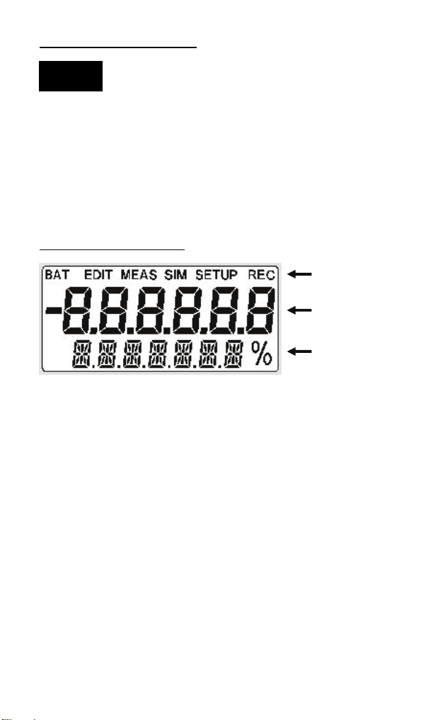
Liquid Crystal Display (LCD)
The LCD displays:
• current Functional Mode and/or state via icons along top of display
• primary measurements via the large middle segments
• menu items and additional information via the bottom alpha-numeric
segments
The LCD incorporates two backlights:
• a green backlight which is user activated via the BACKLIGHT key
• a red backlight which is automatically activated during an over-
range/under-range condition.
The three keys beneath this symbol allow the user to scroll
Mode icons
Measure or
Simulate Values
Menus, units or
other information
During an over-range/under-range condition, the red backlight will over-ride
the green backlight if it was already on. Once the condition is corrected, the
green backlight will be restored to its previous state (assuming the backlight
auto-off timer did not expire).
Notes: 1. The ba
2. The backlight will be automatically disabled when the unit reaches
cklight should be turned off when not needed to conserve
battery power.
battery mode.
Page 6 of 18
Page 9
Functional Modes and States
The unit supports measurement and simulation activities using the following
Functional Modes:
1. Measure - temperature units or measure mV; MEAS icon shown at
top of display
2. Simulate, Manual - simulate fixed values of temperature units or
mV; SIM icon shown at top of display
3. Simulate, Auto - simulate step or ramp output functions in
temperature units or mV; SIM icon shown at top of display
Each Functional Mode has three possible States:
1. Run - active measurement or simulation; MEAS or SIM icon
shown at top of display
2. Setup – access navigation menus; MEAS & SETUP or SIM &
SETUP icons shown at top of display
3. Edit Setup - edit a parameter within a navigation menu; “EDIT
EAS & SETUP” or “EDIT, SIM & SETUP” icons shown at top
M
of display
The T/C calibrator will power up in its previous functional mode when turned
ON. Example: if previous use was SIM (Auto), then next power up will
default to SIM (Auto). Simulation will restart when user confirms the desired
setup and presses the ENTER key (two times).
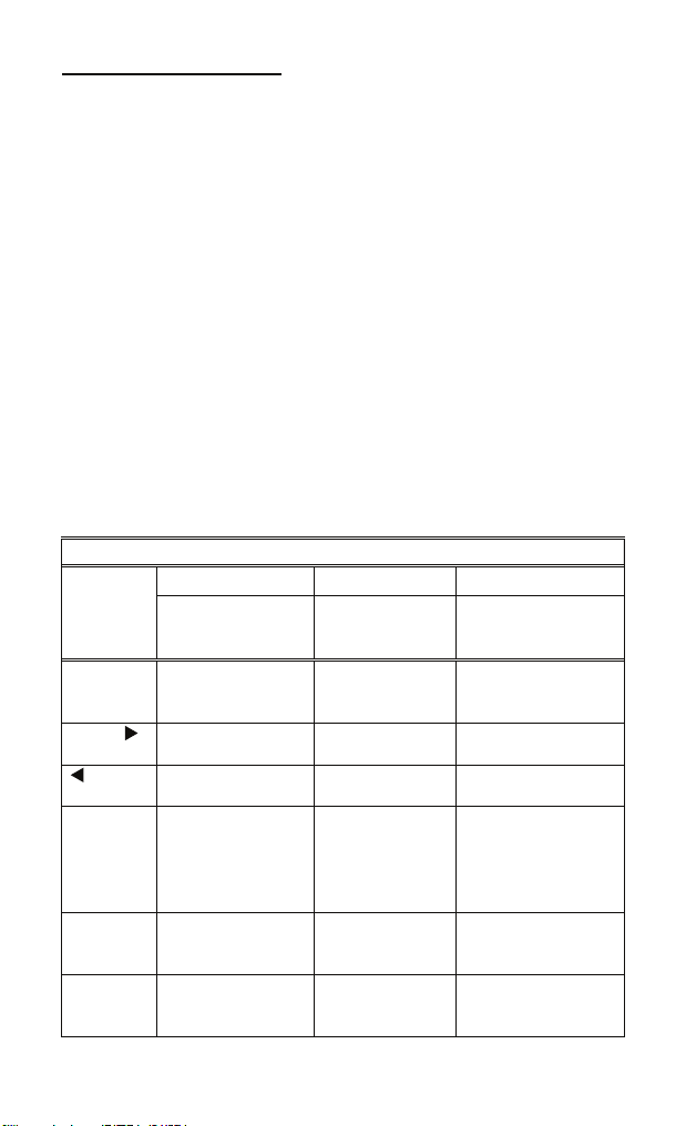
See the table below for functional modes, states and key functions.
FUNCTIONAL MODES, STATES, AND KEY FUNCTIONS
Run Setup Edit Setup
Keys
SETUP Enters Setup state,
FUNC Next Functional
UNITS Next engineering
ENTER Toggles lower
Increment
(+) Group
Decrement
(-) Group
MEAS
or
SIM
or ends simulation
activity
mode
unit
display line
between TC type /
temp. unit and %
of range (SIM only)
MEAS: --SIM Manual:
Change values
MEAS: --SIM Manual:
Change values
MEAS SETUP
or
SIM SETUP
Back one menu
level, or exits
Setup state
Next menu item ---
Previous menu
item
Selects menu
item
--- Change value
--- Change value
Page 7 of 18
EDIT SIM SETUP
Discards changes and
exits Edit Setup state
Saves changes and
exits Edit Setup state
EDIT MEAS
SETUP, or
---
,
Page 10
T/C Measurement
• When the T/C calibrator is turned on the display defaults to the previous
mode it was in with the previous T/C type and Unit. To change the mode
press the FUNC
Measure mode, press the
key until the Measure mode is obtained. Once in
UNITS key until the desired unit is obtained.
• Press the SETUP key to enter the initial setup menu for the current
functional mode. To go back one menu item press the
advance the menu, press the FUNC
the Setup state and returns to the Measure mode.
• ENTER key accepts the menu item to edit and saves the selection. During
the SETUP EDIT state the
and the FUNC
• T/C measurements can be recorded to memory either manually or
automatically. See the Record Mode section of this manual for more
information.
• When an over-range/under-range message is displayed, the unit is
measuring values outside the specified range for a particular T/C type (See
the T/C Measurement Accuracy Table for specified ranges). The red
backlight will illuminate and “----” will be displayed.
• If a thermocouple has not been connected to the unit “T/C OPEN” will be
displayed.
T/C Simulation (Manual)
• When unit is turned on the display defaults to the previous mode with the
last T/C type and Units chosen. To enter the Simulation Manual mode
press the FUNC
SETUP key.
T/C Simulation (Auto)
• When unit is turned on the display defaults to the previous mode with the
last T/C type and Units chosen. To enter the Simulation Auto mode press
the FUNC
key advances one increment value.
key until SIM MANUAL appears, then press the
key until SIM AUTO appears, then press the SETUP key.
key. SETUP key also backs out of
UNITS key goes back one increment value,
UNITS key. To
Page 8 of 18
Page 11

MEAS SETUP: Measure Mode Setup menu structure
T/C TYPE select ENTER to access submenus
mV engineering units are mV
B engineering units are temperature only
E engineering units are temperature only
J engineering units are temperature only
K engineering units are temperature only
N engineering units are temperature only
R engineering units are temperature only
S engineering units are temperature only
T engineering units are temperature only
OFF TMR select ENTER to access submenus
30 MIN shuts off in 30 min without new key stroke
OFF must use ON/OFF key to shut off
F RECAL select ENTER to access submenu
ZERO set zero. See the “Zeroing” section
VIEW view previously recorded values
RECORD s
MANUAL press ENTER button to record values
AUTO values automatically recorded every 5 seconds
elect ENT
ER to access submenus
Note: Main and submenus are continuous scrolling menus. Use
scroll through the menus.
Page 9 of 18
or to
Page 12

SIM (MANUAL) SETUP: Simulation Mode’s Manual menu structure
VALUE
ADJUST Press ENTER & use increment or decrement group
keys to set a numeric value, press ENTER to start
UNITS Select desired unit of simulation
C engineering units are ºC
F engineering units are ºF
R engineering units are ºR
K engineering units are K
TC TYPE Select T/C type or mV
mV engineering units are mV
B engineering units are temperature only
E engineering units are temperature only
J engineering units are temperature only
K engineering units are temperature only
N engineering units are temperature only
R engineering units are temperature only
S engineering units are
T engineering units are temperature only
0 – 100 Outputs 0% and 100% of setup
START Starts 0% of range; ENTER toggles to 100%, 0%...
UNITS Edit units corresponding to 0 – 100, same as above
TC TYPE Select T/C type, same as above
URV Upper Range Value for T/C and unit selected
press enter & use +/ – keys
LRV Lower Range Value for T/C and unit selected
press enter & use +/ – keys
tempera
ture only
STEP 25% Outputs 0, 25, 50, 75 and 100% of setup below
Notes: 1. Main and submenus are continuous, scrolling menus. Use
START Starts 0%, ENTER increases 25% to 100% & back
UNITS Edit unit for STEP 25%, same as above
TC Select T/C type, same as above
URV Upper Range Value for T/C and unit selected
press enter & use +/ – keys
LRV Lower Range Value for T/C
press enter & use +/ – keys
to scroll through the menus.
2. Use SETUP key to discontinue simulation activity.
Page 10 of 18
and u
nit selected
or
Page 13

SIM (AUTO) SETUP: Simulation Mode’s Manual menu structure
AUTO Press SETUP to enter
A.STEP 1 Title of Auto Step 1 simulation; setup saved here
START Starts A.STEP 1
UNITS Select desired unit of simulation
C engineering units are ºC
F engineering units are ºF
R engineering units are ºR
K engineering units are K
TC TYPE Select T/C type or mV
mV engineering units are mV only
B engineering units are temperature only
E engineering units are temperature only
J engineering units are temperature only
K engineering units are temperature only
N engineering units are temperature only
R engineering units are temperature only
S engineering units are temperature only
T engineer
URV Upper Range Value for T/C and unit selected,
press enter & use +/ – keys
LRV Lower Range Value for T/C and unit selected,
press enter & use +/ – keys
STEPS Input number of steps desired for test
UP press enter & use + / – keys
DOWN press enter & use + / – keys
DWELL Select desired dwell time for test points
Manual Manually advance simulation
5 SEC. Auto advance simulation every 5 seconds
A.STEP 2
A.STEP 3
A.RAMP 1 Title of Auto Ramp 1 simulation; setup saved here
10 SEC. Auto advance simulation every 10 seconds
same as A.STEP 1 above
same as A.STEP 1 above
START Starts A.RAMP 1
UNITS Select desir
C engineering units are ºC
F engineering units are ºF
R engineering units are ºR
K engineering units are K
TC TYPE Select T/C type or mV
mV engineering units are mV only
B engineering units are temperature only
E engineering units are temperature only
J engineering units are temperature only
K engineering units are temperature only
N engineering units are temperature only
for subsequent re-use
nits are temperature only
ing u
for subsequent re-use
nit of simulation
ed u
Page 11 of 18
Page 14

R engineering units are temperature only
S engineering units are temperature only
T engineering units are temperature only
URV Upper Range Value for T/C and unit selected,
press enter & use +/ – keys
LRV Lower Range Value for T/C and unit selected,
press enter & use +/ – keys
UP TIME Select desired ramp time from LRV to URV,
press enter & use +/ – keys
DN TIME Select desired ramp time from URV to LRV,
press enter & use +/ – keys
DELAY Select desired start delay time for test,
press enter & use +/ – keys
A.RAMP 2
same as A.RAMP 1 above
A. RAMP 3
same as A.RAMP 1 above
Note: 1. Main and submenus are continuou
to scroll through the menus.
2. Use SETUP key to discontinue simulation activity.
Page 12 of 18
lling menus. Use or
s, scro
Page 15

Engineering Units Select
Engineering Units are conveniently selected when actively measuring or in
Manual Simulation mode. Press the
following: ºC, °F, ºR, K. NOTE: to display mV units, select the mV option
under MEAS SETUP / TC TYPE. The
display units for this TC TYPE.
Record Mode
The T/C calibrator can store up to 240 temperature measurements in a single
record (REC) session. For maximum flexibility, a REC session can be:
• Automatic - the current value is automatically stored every 5 seconds, for
up to 20 minutes.
• Manual - the current value is stored every time the Enter key is pressed, up
to 240 times.
Both types of REC sessions can store between 1 and 240 measurements. The
measurement data is preserved in non-volatile memory until another REC
session is started.
RECORD Data:
UNITS key to display any of the
UNITS key will not change
To start a manual
or key until RECORD is displayed. Press ENTER and then or
then
key until MANUAL is displayed. Press ENTER. Previously stored
information is deleted and the unit enters Record Manual Mode. The REC
icon flashes in upper right. Press Enter to save a displayed value to memory.
Pressing SETUP key ends the session.
To start an automatic
and then
or key until AUTO is displayed. Press ENTER. Previously stored
information is deleted and the unit enters Record Auto Mode. The REC icon
flashes in upper right. Values are stored every 5 seconds until the SETUP key
is pressed to end the session or 240 values are saved.
REC is displayed on the lower display line each time a sample is stored. After
240 measurements have been recorded or the SETUP key is pressed, the REC
session will stop and the RECORD Data mode will automatically exit to
Measure Mode.
VIEW Recorded Data:
To view the results of a REC session from Measure Mode, press SETUP key
and then
is shown in upper right. Display will show recorded value 1 of X (1/X).
Pressing ENTER will toggle to show the T/C type and engineering unit. The
or key moves to previous or next recorded value, respectively.
record session from Measure Mode, press SETUP key and
record session from Measure Mode, press SETUP key
or key until RECORD is displayed. Press ENTER and then
or key until VIEW is displayed. Press ENTER. The REC icon
Page 13 of 18
Page 16

OFF Timer
To help conserve battery life, the unit can be programmed to shut off
automatically after 30 minutes of keypad inactivity. From Measure Mode,
press SETUP and then
ENTER key and use + or – key to display OFF or 30 MIN from menu. Press
ENTER key to save selection. Press SETUP again to return to Measure Mode.
Zeroing
Preparation: Allow the T/C calibrator and supplied Shorting Plug (p/n Z9A83)
to soak at room temperature for 30 minutes in a controlled temperature
environment. Record the room temperature immediately prior to zeroing.
or key until OFF TMR is displayed. Press the
Zeroing: From Measure Mode, press SETUP once and then the
until F RECAL is displayed. Press the ENTER key to display ZERO. Press
ENTER to start ZERO process. Display will show SHORT. Install the
Shorting Plug (white, mini-T/C connector with internal copper short) on the
unit’s mini-T/C connection and press ENTER key. Display will show BUSY.
When ZERO is successfully completed, the message “ZERO PASSED” is
briefly displayed and the unit is automatically returned to the Measure Mode.
Remove the Shorting Plug. The new temperature reference for the unit will be
the ambient temperature recorded prior to zeroing. (Note: factory reference
temperature is 23°C.)
If the ZERO is unsuccessful, the messag
briefly. In this case, check to be sure the Shorting Plug is properly installed
and repeat the ZERO process. If “ZERO FAILED” appears again contact your
supplier for technical support.
e “ZERO
FAILED” will be displayed
or key
Page 14 of 18
Page 17

Specifications
Type and Range:
T/C types B, E, J, K, N, R, S, T & milli-volts
Milli-volts range -15mV to +80.00 mV
T/C Measurement & Simulation Accuracy: See Table below
mV Accuracy: 0.005% of reading ±6µV
mV Temp. Effect: ±2 µV /°C (Factory Ref. Temp. = 23°C)
Cold Junction Effect: ±0.05°C/°C
Cold Junction Accuracy: ±0.1°C at 25°C
T/C Resolution:
T/C types E, J, K, N, T: 0.1°C
T/C types B, R, S: 1°C
mV: 0.001 mV (1 µV)
Temperature:
Storage = -40°C to +85°C (-40°F to +185°F)
Operating = -10°C to +50°C (14°F to +122°F)
Humidity: 10% to 90% Rh
Connection:
Measure: standard mini-T/C connector
Simulate: standard mini-T/C connector
Zero: supplied mini-T/C connector with internal copper short
Maximum Input Voltage: 30VDC
Battery Type:
3 x AA battery, field replaceable.
Battery Operation:
>100 hours continuous use without the backlight for measure
or simulation modes, 1 year shelf life, low battery warning at
approximately 2 hours remaining run time.
Enclosure:
(6.5” × 3.2” × 1.1”) Polycarbonate, Permanently Static
Dissipative, ESD Protection
Enclosure with Boot:
(6.8” × 3.5” × 1.3”)
Page 15 of 18
Page 18

T/C Measurement & Simulation Accuracy Table*
Find T/C type in left column and follow the row across to the temperature range of
interest. Then follow the column up to determine the potential error in degrees C.
T/C
±3.0°C±2.0°C±1.0°C±0.5°C±0.4°C±0.3°C±0.2°C±0.1°
Type
E
J
K
N
T
R -50 to
S -50 to
27°C
25°C
27 to
736°C
25 to
1179°C
736 to
1768°C
1179 to
1768°C
-200 to
-179 to
-179°C
-200 to
-165°C
-200 to
1372°C
-200 to
110°C
-200 to
-168 to
-168°C
-86°C
15°C
-165 to
1200°C
110 to
1300°C
-86 to
346°C
C
15 to
1000°C
346 to
400°C
B 250 to
295°C
295 to
605°C
605 to
1301°C
1301 to
1820°C
*Notes: 1. Accuracy stated above applies to all T/C measurements and all manual
(non-ramp) T/C simulations.
2. Cold junction effect at 25º C included in above table.
Page 16 of 18
Page 19

Certification
The T/C calibrator is EMI/ESD compliant to the test specification EN61326.
The unit is for general purpose use only. Do not use in potentially hazardous
atmospheres.
Changing the Batteries
The T/C calibrator is powered by three, 1.5 volt AA size batteries. The “BAT”
icon in upper left of display will activate when battery output drops below a
threshold level. Approximately 2 hours of life remain from that point.
Replace all three AA batteries at the same time for best performance.
To replace the batteries, locate the battery compartment at the lower rear of
the unit. Remove the screws located at the top center and bottom center of the
battery cover by turning them coun
te
rclockwise until fully disengaged from
the base. Remove the cover. Do not remove the pink anti-static foam that is
attached to the inside of the battery cover. This foam is necessary to
properly secure the batteries under specified shock and vibration
conditions.
Remove the batteries by pulling the positive side first straight out of the
battery compartment. Note the positive (+) and negative ( – ) battery polarity
markings at the bottom of the compartment, as shown below.
Install the three batteries by sliding them into the bottom of the battery slots,
positive (+) end first, making sure the polarity markings on the batteries align
with the markings molded into the battery compartment. When a battery is
installed with the polarity reversed, the stand-offs prevent the negative battery
terminal from contacting the positive terminal in the battery compartment.
The unit will not power up in this condition; to correct, simply reverse the
battery to correct the polarity.
With the batteries secured in the battery compartment, replace the
compartment cover. The cover has only one orientation for correct alignment.
The “WARNING
battery cover must b
DO NOT OPEN IN EXPLOSIVE ATMOSPHERE
” statement on the
e visible and aligned in the approximate middle of the
case. To secure the cover, torque the screws clockwise to 1.6 in-lbs. Do not
over tighten.
Page 17 of 18
Page 20

User Connections
Connection: Standard mini-T/C Connector (Measure and Simulate)
Warning:
damaged if the mating plugs are misaligned during installation. Take care to
properly align the mating plug prior to pressing it into the calibrator’s miniT/C jack.
The copper receiver blades of the mini-T/C connector can be
Contact Information
If the unit is damaged, it should be returned to the factory for serve. In this
case, contact your supplier for a return number.
Page 18 of 18
Page 21

WARRANTY/DISCLAIMER
OMEGA ENGINEERING, INC. warrants this unit to be free of defects in materials
and workmanship for a period of 13 months from date of purchase. OMEGA’s
WARRANTY adds an additional one (1) month grace period to the normal one
(1) year product warranty to cover handling and shipping time. This ensures
that OMEGA’s customers receive maximum coverage on each product.
If the unit malfunctions, it must be returned to the factory for evaluation.
OMEGA’s Customer Service Department will issue an Authorized Return (AR)
number immediately upon phone or written request. Upon examination by
OMEGA, if the unit is found to be defective, it will be repaired or replaced at no
charge. OMEGA’s WARRANTY does not apply to defects resulting from any
action of the purchaser, including but not limited to mishandling, improper
interfacing, operation outside of design limits, improper repair, or unauthorized
modification. This WARRANTY is VOID if the unit shows evidence of having
been tampered with or shows evidence of having been damaged as a result of
excessive corrosion; or current, heat, moisture or vibration; improper specification; misapplication; misuse or other operating conditions outside of OMEGA’s
control. Components in which wear is not warranted, include but are not limited
to contact points, fuses, and triacs.
OMEGA is pleased to offer suggestions on the use of its various products.
However, OMEGA neither assumes responsibility for any omissions or errors
nor assumes liability for any damages that result from the use of its
products in accordance with information provided by OMEGA, either verbal
or written. OMEGA warrants only that the parts manufactured by the
compamy will be as specified and free of defects. OMEGA MAKES NO
OTHER WARRANTIES OR REPRESENTATIONS OF ANY KIND WHATSOEVER,
EXPRESSED OR IMPLIED, EXCEPT THAT OF TITLE, AND ALL IMPLIED
WARRANTIES INCLUDING ANY WARRANTY OF MERCHANTABILITY AND
FITNESS FOR A PARTICULAR PURPOSE ARE HEREBY DISCLAIMED.
LIMITATION OF LIABILITY: The remedies of purchaser set forth herein are
exclusive, and the total liability of OMEGA with respect to this order,
whether based on contract, warranty, negligence, indemnification, strict
liability or otherwise, shall not exceed the purchase price of the component
upon which liability is based. In no event shall OMEGA be liable for
consequential, incidental or special damages.
CONDITIONS: Equipment sold by OMEGA is not intended to be used, nor shall
it be used: (1) as a “Basic Component” under 10 CFR 21 (NRC), used in or with
any nuclear installation or activity; or (2) in medical applications or used on
humans. Should any Product(s) be used in or with any nuclear installation or
activity, medical application, used on humans, or misused in any way, OMEGA
assumes no responsibility as set forth in our basic WARRANTY / DISCLAIMER
language, and, additionally, purchaser will indemnify OMEGA and hold OMEGA
harmless from any liability or damage whatsoever arising out of the use of the
Product(s) in such a manner.
RETURN REQUESTS / INQUIRIES
Direct all warranty and repair requests/inquiries to the OMEGA Customer
Service Department. BEFORE RETURNING ANY PRODUCT(S) TO OMEGA,
PURCHASER MUST OBTAIN AN AUTHORIZED RETURN (AR) NUMBER FROM
OMEGA’S CUSTOMER SERVICE DEPARTMENT (IN ORDER TO AVOID
PROCESSING DELAYS). The assigned AR number should then be marked on
the outside of the return package and on any correspondence.
The purchaser is responsible for shipping charges, freight, insurance and proper
packaging to prevent breakage in transit.
FOR WARRANTY
RETURNS, please
have the following information
available BEFORE contacting OMEGA:
1. Purchase Order number under
which the product was
PURCHASED,
2. Model and serial number of the
product under warranty, and
3. Repair instructions and/or specific
problems relative to the product.
FOR NON-WARRANTY REPAIRS,
consult OMEGA for current repair
charges. Have the following information
available BEFORE contacting OMEGA:
1. Purchase Order number to cover the
COST of the repair,
2. Model and serial number of the
product, and
3. Repair instructions and/or specific
problems relative to the product.
OMEGA’s policy is to make running changes, not model changes, whenever an
improvement is possible. This affords our customers the latest in technology
and engineering.
OMEGA is a registered trademark of OMEGA ENGINEERING, INC.
© Copyright 2008 OMEGA ENGINEERING, INC. All rights reserved. This docu-
ment may not be copied, photocopied, reproduced, translated, or reduced to
any electronic medium or machine-readable form, in whole or in part, without
the prior written consent of OMEGA ENGINEERING, INC.
Page 22

Where Do I Find Everything I Need for
Process Measurement and Control?
OMEGA…Of Course!
Shop online at omega.com
sm
TEMPERATURE
Thermocouple, RTD & Thermistor Probes,
Connectors, Panels & Assemblies
Wire: Thermocouple, RTD & Thermistor
Calibrators & Ice Point References
Recorders, Controllers & Process Monitors
Infrared Pyrometers
PRESSURE, STRAIN AND FORCE
Transducers & Strain Gages
Load Cells & Pressure Gages
Displacement Transducers
Instrumentation & Accessories
FLOW/LEVEL
Rotameters, Gas Mass Flowmeters & Flow Computers
Air Velocity Indicators
Turbine/Paddlewheel Systems
Totalizers & Batch Controllers
pH/CONDUCTIVITY
pH Electrodes, Testers & Accessories
Benchtop/Laboratory Meters
Controllers, Calibrators, Simulators & Pumps
Industrial pH & Conductivity Equipment
DATA ACQUISITION
Data Acquisition & Engineering Software
Communications-Based Acquisition Systems
Plug-in Cards for Apple, IBM & Compatibles
Data Logging Systems
Recorders, Printers & Plotters
HEATERS
Heating Cable
Cartridge & Strip Heaters
Immersion & Band Heaters
Flexible Heaters
Laboratory Heaters
ENVIRONMENTAL
MONITORING AND CONTROL
Metering & Control Instrumentation
Refractometers
Pumps & Tubing
Air, Soil & Water Monitors
Industrial Water & Wastewater Treatment
pH, Conductivity & Dissolved Oxygen Instruments
M4720/0309
Manual Z1017M-A EO 6632 Mar. 2009
 Loading...