

Page 1
Page 2

Page 3

Table of Contents
I. PANEL DESCRIPTION...............................................................1
II. OPERATING INSTRUCTION ................................................6
1. M A OUTPUT..................................................................................... 6
1a. General Operation 4 - 20mA ...................................................... 6
1b. Select 0 - 20mA or 0 - 24mA ...................................................... 8
1c. Enter a value less than 1............................................................ 9
2. M V, V OUTPUT................................................................................ 9
2a. General Operation 0 - 100mV..................................................... 9
2b. Select 0 - 1V or 0 - 12V .............................................................11
2c. Enter a value less than 1...........................................................12
3. HZ, FREQUENCY OUTPUT.................................................................12
4a. General Operation ....................................................................14
4b. Select °C, or °F.......................................................................16
4c. Select K, J, E, or T type Thermocouple.....................................17
4d. Enter a Negative Temperature ...................................................18
5. % INPUT IN THE MA, M V, V FUNCTIONS................................................19
6. EASY STEP IN THE MA, M V, AND V FUNCTIONS .....................................21
7. AUTO RAMP IN THE MA, MV, AND V FUNCTION ......................................23
8. HOW TO GET NEGATIVE OUTPUT...........................................................................26
III. ELECTRICAL SPECIFICATION............................................27
IV. USE THE AC ADAPTER........................................................32
V. USE EXTERNAL BATTERY PACK.......................................33
VI. BATTERY REPLACEMENT..................................................34
Page 4
I. Panel Description
1
8
-
+
TC
1
4-20mA
0-20mA
4
5
mV 1V
¢X2¢X
C F
12V
6
708
¡D
_
%
%
%
PROCESS
7
CALIBRATOR
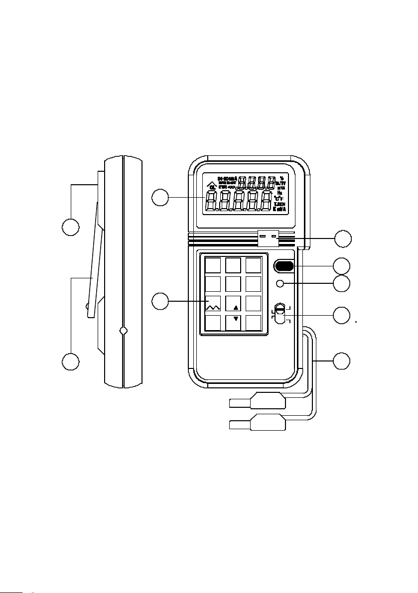
1. LCD DISPLAY 6. NUMERICAL & FUNCTION KEYPAD
2. THERMOCOUPLE SOCKET 7. STAND
3. ON/OFF BUTTON 8. AC ADAPTOR INPUT SOCKET
4. SHIFT BUTTON 9. OUTPUT LEADS
5. FUNCTION SELECT SWITCH
3
0-24mA
6
K J E T
9
ENTER
ON/OFF
SHIFT
V
mV
Hz
mA
C
¢X
F
¢X
2
3
4
5
9
1
Page 5
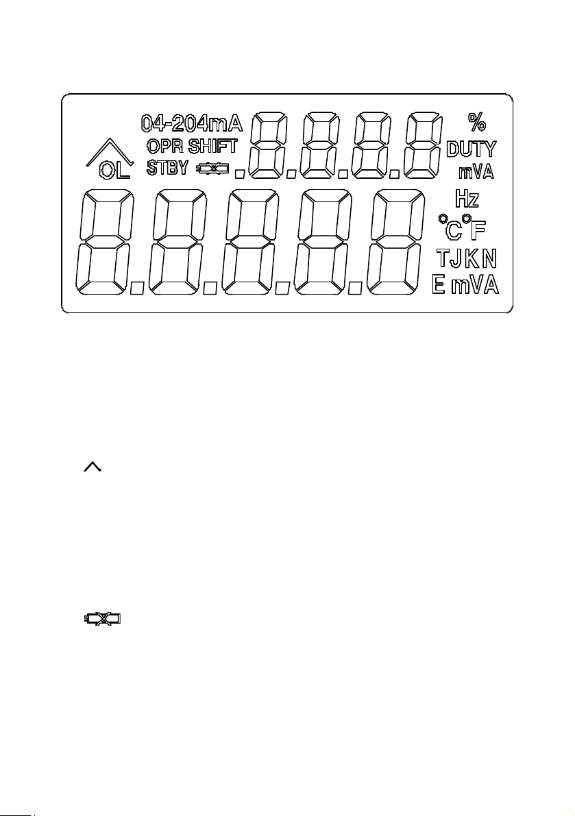
1. mVAHz: Units
2. 04-204mA : Range of mA
3. %: Percentage
4. JKET: Thermocouple type
5. : Ramp
6. OPR : Operate, Output, Normal
7. OL: Overload, Output, Abnormal
8. STBY: Standby, Internal Calibration in Progress
9. SHIFT: Select SHIFT functions
10. : Battery low
2
Page 6
1 2 3
4-20mA
0-20mA
0-24mA
4
mV 1V
12V
7
¡D
_ %
%
1
5
C F
¢X¢X
8
%
0
6
K J E T
9
ENTER
1 2 3
.
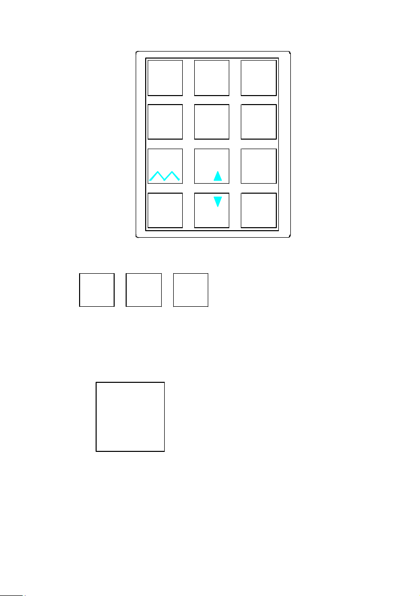
Press SHIFT button, and then press one of these three buttons to select
desired mA range
2.
4-20mA 0-20mA 0-24mA
4
mV 1V
12V
Press SHIFT button, then press this button to select desired mV or V range
3
Page 7
3.
5
C F¢X ¢X
Press SHIFT button, then press this button to select ° C or ° F
4.
6
K J E T
Press SHIFT button, then press this button to select desired type of
thermocouple.
5.
7
Press SHIFT button, then press this button to perform auto-ramp function.
To stop the auto-ramp function, press this button again
4
Page 8
6.
¡D
_
%
Press this button to enter negative temperature. Or press SHIFT button,
then press this button first to enter percentage in the mA, mV, and V
functions.
7.
8
%
%
While the calibrator is in the SHIFT mode, and the percentage is entered,
press this button to increment %.
8.
ENTER
Always press this button to complete the entry of numbers.
0
5
Page 9
II. Operating Instruction
1.mA Output
1a. General Operation 4 - 20mA
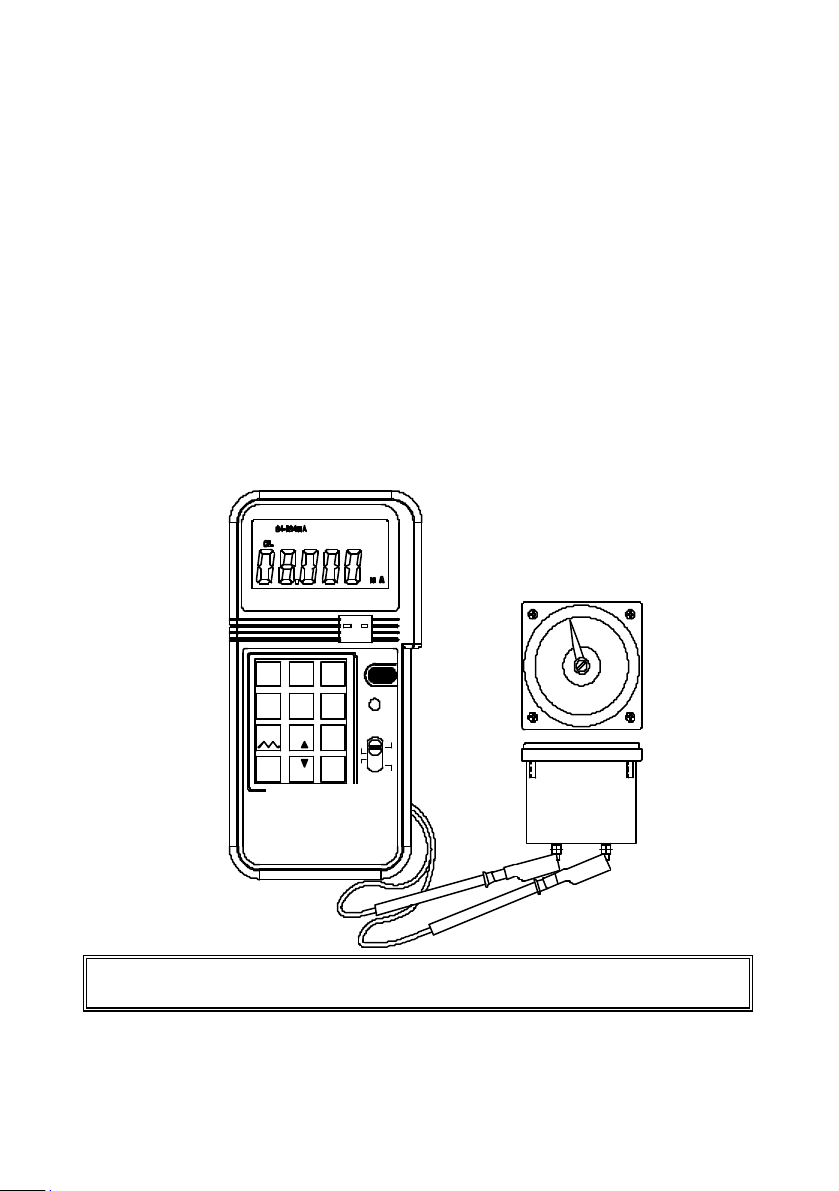
1 Turn the power on, and wait until the STBY symbol disappears
(about 1 min.)
2 Plug the test leads into the output connectors of calibrator
accordingly (Black to black, red to red). Attach alligator clip if
necessary.
3 Move the sliding switch to mA position
4 Press the keypad (including the decimal point) to enter the value
of mA directly.
5 Using the test leads or alligator clips, touch or clip on the
terminals to be calibrated.
+-
TC
ON/OFF
31 2
4-20mA
mV 1V
0-24mA
0-20mA
4
5
¢X
C F
¢X
12V
7
8
%
¡D
_
%
%
0
K J E T
ENTER
SHIFT
6
V
9
mV
Hz
8.000mA
mA
C
¢X
¢XF
PROCESS
CALIBRATOR
Note: Always waits until STBY (standby) symbol in the LCD disappears
before any operation.
6
Page 10

Note: Maximum 5 digits can be entered. If users enter less than 5 digits
(1 to 4 digits), users must press ENTER button to indicate the end of
entry. If users enter 5 or more digits, calibrator will automatically end the
entry and output specified value current.
7
Page 11
1b. Select 0 - 20mA or 0 - 24mA
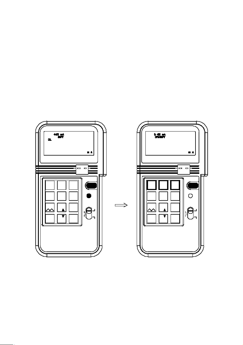
The default setting for mA function is 4 - 20mA. But users can select 0 20mA or 0 -24 mA by pressing the SHIFT button to enter the SHIFT mode.
Then press the NUMBER 2 or NUMBER 3 button to select desired DC
current range. After desired range is selected, press the shift button to exit
the SHIFT mode. Corresponding current range symbol will be displayed in
the LCD.
- +
TC
3
0-24mA
K J E T
9
ENTER
ON/OFF
SHIFT
V6mA
mV
Hz
C
¢X
F¢X
21
4-20mA
0-20mA
4
mV 1V
C F5¢X
¢X ¢X
12V
7
8
%
¡D
_0%
%
PROCESS
CALIBRATOR
8
2
1
4-20mA
4
mV 1V
12V
7 8
¡D
_ %
%
0-20mA
5
%
0
0-24mA
¢X C F
K J E T
ENTER
PROCESS
CALIBRATOR
+
-
TC
ON/OFF
3
SHIFT
6
V
9
mA
mV
Hz
C
¢X
F¢X
Page 12
-
+
TC
1 2
4-20mA
4
mV 1V
12V
7
¡D
_ %
%
0-20mA
5
C F
¢X ¢X
8
%
0
3
0-24mA
6
K J E T
9
ENTER
ON/OFF
SHIFT
V
mV
Hz
mA
C
¢X
F¢X
PROCESS
CALIBRATOR
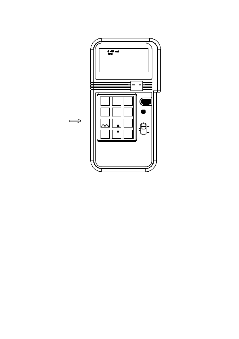
1c. Enter a value less than 1
In the mA functions, the standard way to enter a value less than 1 is to
press leading 0 before pressing the decimal point. Though the decimal
point can be entered, the decimal point will not be shown in the LCD.
2. mV, V Output
2a. General Operation 0 - 100mV
1. Turn the power on, and wait until the STBY symbol disappears
9
Page 13
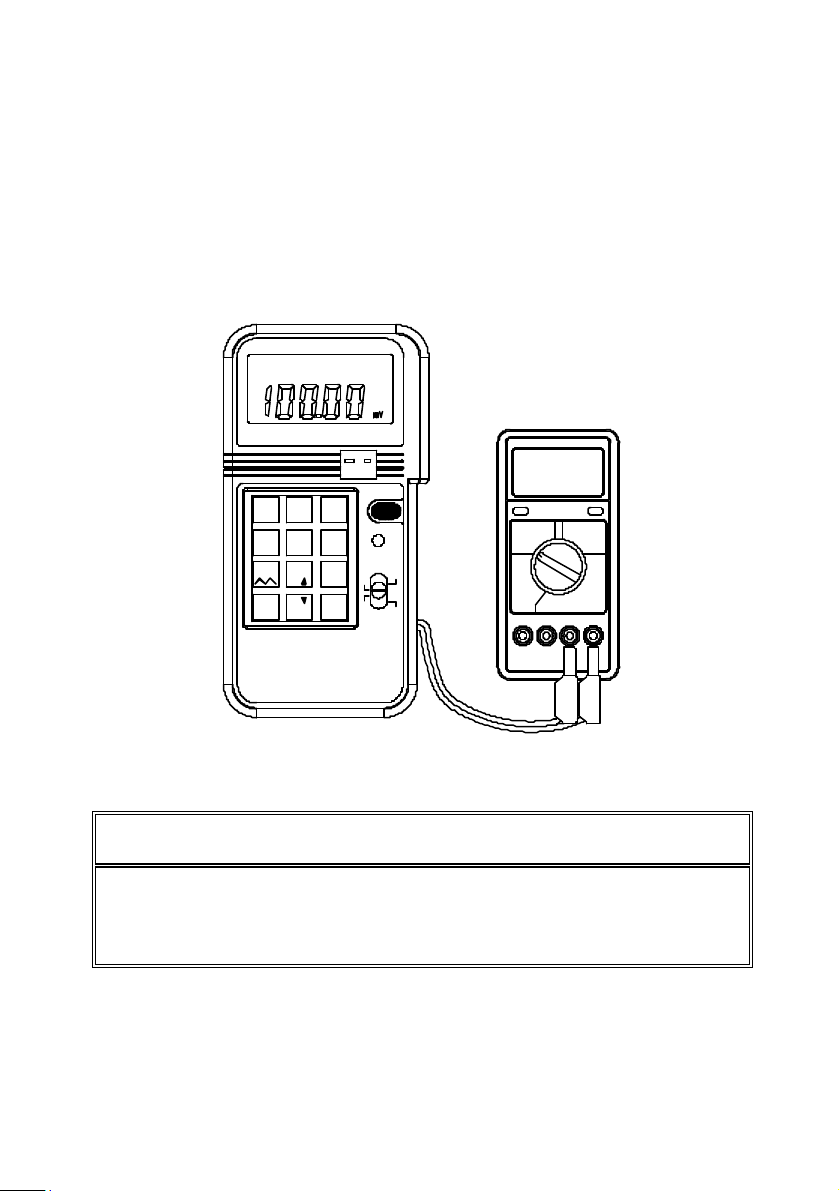
min.).
2. Plug the test leads into the output connectors of calibrator
3. Move the sliding switch to mV, V position
4. Press the keypad (including the decimal point) to enter the value
5. Using the test leads or alligator clips, touch or clip on the
(about 2
accordingly (Black to black, red to red). Attach alligator clip if
necessary.
of mA directly.
terminals to be calibrated.
+-
1 2
4-20mA
mV 1V
12V
¡D
0-24mA
0-20mA
4
5
¢X
C F
K J E T
¢X
7
8
%
_
%
ENTER
0
%
PROCESS
CALIBRATOR
TC
ON/OFF
3
SHIFT
6
V
9
mA
mV
Hz
¢X C
F
¢X
100.00mV
REDBLACK
Note: Always wait until STBY (standby) symbol in the LCD to disappear
before any operation.
Note: Maximum 5 digits can be entered. If users enter less than 5
digits (1 to 4 digits), users must press ENTER button to indicate the end
of entry. If users enter 5 or more digits, calibrator will automatically end
the entry and output specified value current.
10
Page 14
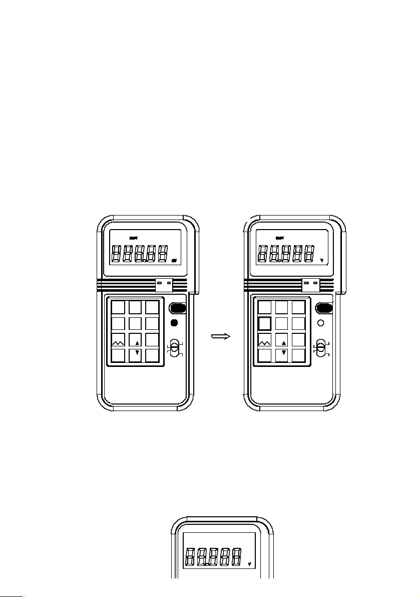
2b. Select 0 - 1V or 0 - 12V
The default setting for mV, V function is 0 - 100.00mV. Users can
select 0 - 1.0000V or 0 -12.000V by pressing the SHIFT button to enter
SHIFT mode. Then press the NUMBER 4 button repeatedly to select
desired DC voltage range. After desired range is selected, press the
SHIFT button again to exit the SHIFT mode. Corresponding voltage
range symbol will be displayed in the LCD.
-
+
TC
0-24mA
K J E T
ENTER
ON/OFF
3
SHIFT
6
V
9
mA
mV
Hz
C
¢X
¢XF
1
2
4-20mA
0-20mA
4
5
mV 1V
C F¢X
¢X 12V
12V
7
8
%
¡D
_
%
%
0
PROCESS
CALIBRATOR
11
2
1
4-20mA
0-20mA
0-24mA
4
mV 1V
C F7¢X¢X
K J E T
8
%
¡D
%_
ENTER
0%
PROCESS
CALIBRATOR
-
+
TC
ON/OFF
3
SHIFT
65
V
9
mA
mV
Hz
C
¢X
F¢X
Page 15

2c. Enter a value less than 1
In the mV/V functions, the standard way to enter a value less than 1 is
to press
the leading 0 before pressing the decimal point. Though the decimal
point can be entered first, the decimal point will not be shown in the
LCD.
3. Hz, Frequency Output
1. Turn the power on, then plug the test leads into the output connectors
of calibrator accordingly (Black to black, red to red). Attach alligator
clip if necessary.
2. Move the sliding switch to Hz position
12
Page 16
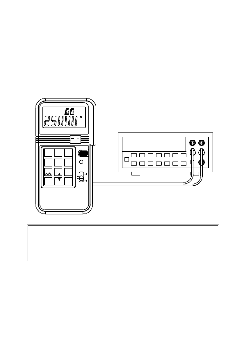
3. Press the keypad (excluding the decimal point) to enter the value of
Hz directly.
4. Using the test leads or alligator clips, touch or clip on the terminals
to be calibrated.
5.Because not all the frequencies are available between 126 to
62500Hz, calibrator will automatically adjust and display the users
input value to a frequency, which is available and always larger or
equal to users input.
-
+
1 2
0-20mA 0-24mA4-20mA
4
5
mV 1V
C F
¢X
K J E T
¢X
12V
8
7
%
¡D
%
_
ENTER
0
%
PROCESS
CALIBRATOR
TC
ON/OFF
3
SHIFT
6
9
mAV
mV
Hz
C¢X
F
¢X
25000Hz
Note: The resolution of Hz function is 1 Hz. For the range 1-125Hz, all
the frequencies in between are available. But for the range 126 62500Hz, not all the frequencies are available (total 604 frequencies
available). Please refer to section III Electrical Specifications for
available frequencies.
4. Thermocouple Calibration of °C, °F.
13
Page 17
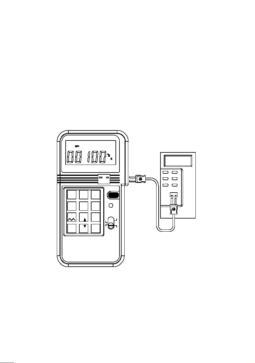
4a. General Operation
1. Turn the power on, and wait until the STBY symbol disappears
(about 1 min.).
2. Plug the corresponding connector (K-type connector for K-type
thermocouple, J-type connector for J-type thermocouple, ...) into TC
terminals of calibrator and thermometer to be calibrated.
3. Move the sliding switch to °C, °F position
4. Press the keypad (including the minus - button) to enter the
value of
Temperature directly.
100.0¢XC
4-20mA
4
mV 1V
12V
¡D
_ %
%
C F
¢X
%
0-24mA
5
6
¢X
K J E T
87
9
ENTER
0
321
0-20mA
PROCESS
CALIBRATOR
-
+
TC
ON/OFF
SHIFT
mAV
mV
Hz
C¢X
F
¢X
+
-
- +
-
+
14
Page 18
100.0¢XC
+-
TC
ON/OFF
31 2
4-20mA
4
mV 1V
12V
7
_¡D%%
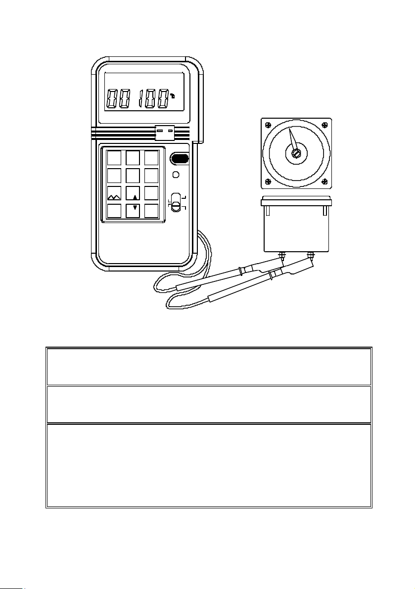
Note: Users can plug the connector into the TC terminals of calibrator
even before the power is turned on for better thermal equilibrium
between the TC terminal and thermocouple connector.
Note: Only in the °C and °F functions, the negative values are allowed
to be entered. To enter negative temperature, press the minus"-"
button first.
Note: Maximum 4 digits (including the "-" sign) can be
entered. If users enter less than 4 digits (1 to 3 digits),
users must press ENTER button to indicate the end of
entry. If users enter 4 or more digits, calibrator will
automatically end the entry and output specified value of
temperature.
0-24mA
0-20mA
5
6
¢X
C F
K J E T
¢X
8
9
%
ENTER
0
PROCESS
CALIBRATOR
SHIFT
V
mA
mV
Hz
C
¢X
F
¢X
15
Page 19
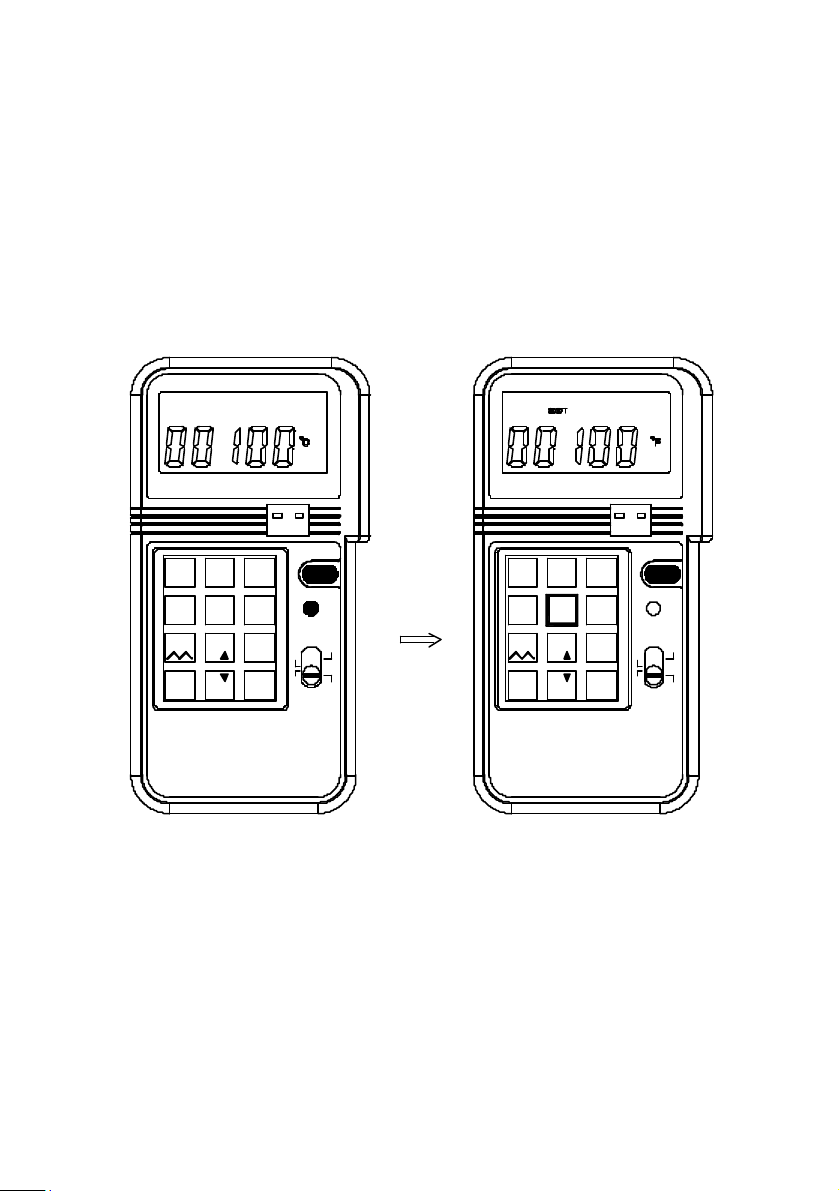
4b. Select °C, or °F
Users can select °C or °F by pressing the shift button to enter SHIFT
mode. Then press the NUMBER 5 button repeatedly to select desired
temperature unit. After desired unit is selected, press the SHIFT button
again to exit the SHIFT mode. Corresponding voltage °C or °F symbol will
be displayed in the LCD.
1
2
4-20mA
0-20mA
4
5
mV 1V
12V
7
¡D
_
%
K J E T
¢X C F
¢X
8
%
%
ENTER
0
PROCESS
CALIBRATOR
-
+
TC
ON/OFF
3
SHIFT
6
V
9
mA
mV
Hz
C¢X
F
¢X
1
4-20mA0-24mA
mV 1V
12V
7 8
¡D
_ %
%
0-20mA
C F¢X ¢X
%
243
0-24mA
5
K J E T
ENTER
0
-
+
TC
ON/OFF
SHIFT
6
9
mAV
mV
Hz
¢X
C
F
¢X
PROCESS
CALIBRATOR
16
Page 20
1 2
0-20mA
4-20mA
4
mV 1V
12V
_¡D%
%
5
C F
¢X ¢X
87
%
0
0-24mA
K J E T
ENTER
PROCESS
CALIBRATOR
+-
TC
ON/OFF
3
SHIFT
6
9
mAV
mV
Hz
C
¢X
¢X
F
+-
TC
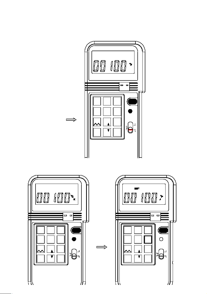
4c. Select K, J, E, or T type Thermocouple
1
Users can select K, J, E, or T type Thermocouple by pressing the shift
button to enter SHIFT mode. Then press the number 6 button repeatedly to
select desired type of thermocouple. After desired type is selected, press
the shift button again to exit the SHIFT mode. Corresponding
thermocouple type (K, J, E, or T) symbol will be displayed in the LCD.
4-20mA
4
mV 1V
12V
7
¡D
_
%
2
0-20mA
5
¢X
8
%
%
0
¢X C F
PROCESS
CALIBRATOR
K J E T
ENTER
ON/OFF
3
SHIFT
6
V
9
mA
mV
Hz
C¢X
F
¢X
17
1
243
4-20mA0-24mA
0-20mA
5
mV 1V
C F¢X ¢X
12V
7 8
%
¡D
_ %
0
%
PROCESS
CALIBRATOR
0-24mA
6
K J E T
9
ENTER
TC
+-
ON/OFF
SHIFT
mV
Hz
mAV
¢X
C
F
¢X
Page 21
+-
TC
1 2
4-20mA
4
mV 1V
12V
_¡D%
%
0-20mA
5
C F
¢X ¢X
87
%
0
3
0-24mA
6
K J E T
9
ENTER
ON/OFF
SHIFT
mV
Hz
mAV
C
¢X
¢X
F
PROCESS
CALIBRATOR
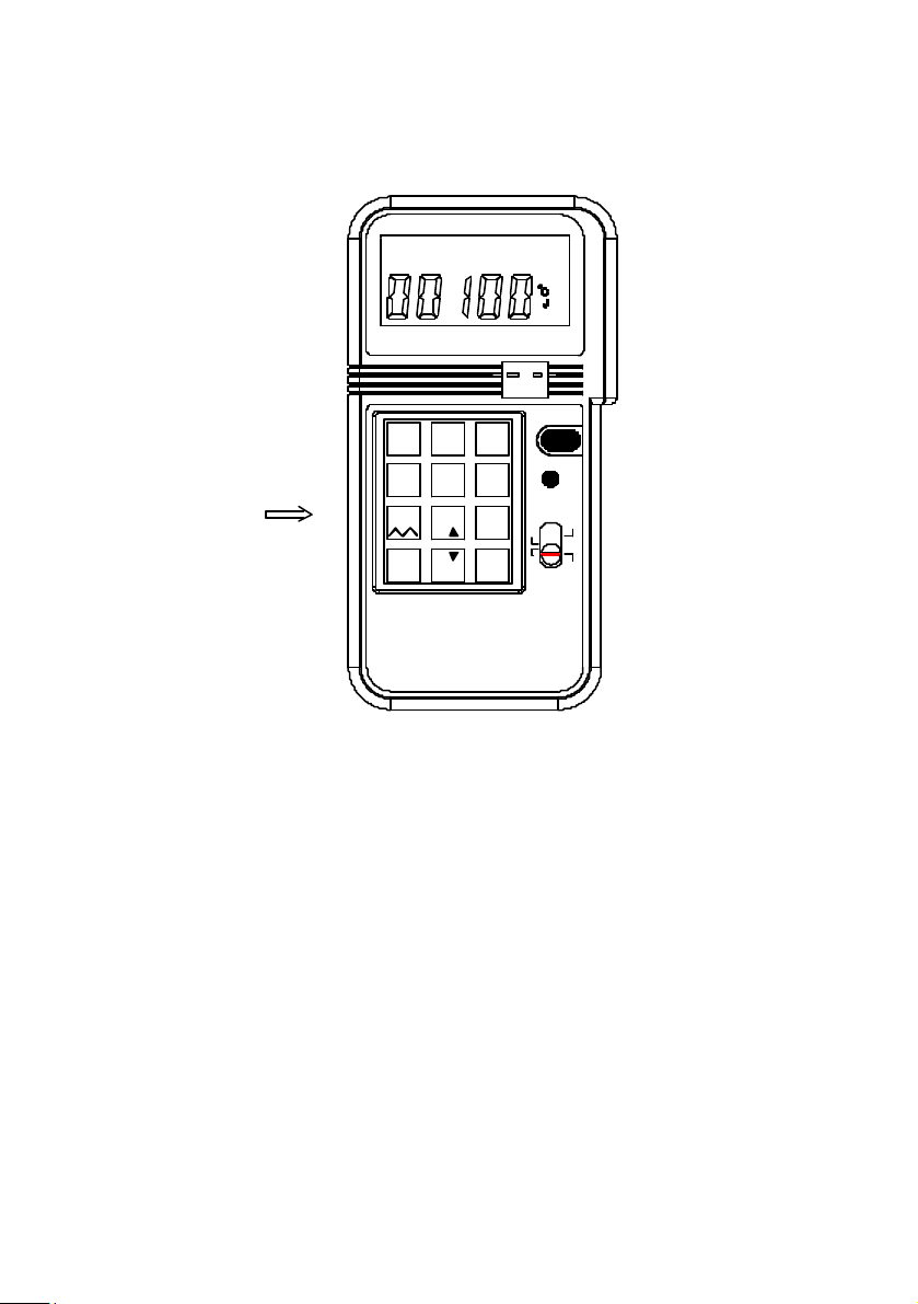
4d. Enter a Negative Temperature
The resolution of temperature is 1 degree, so the decimal point is used a
minus "-" sign. To enter a negative temperature, press the "-" button first.
18
Page 22
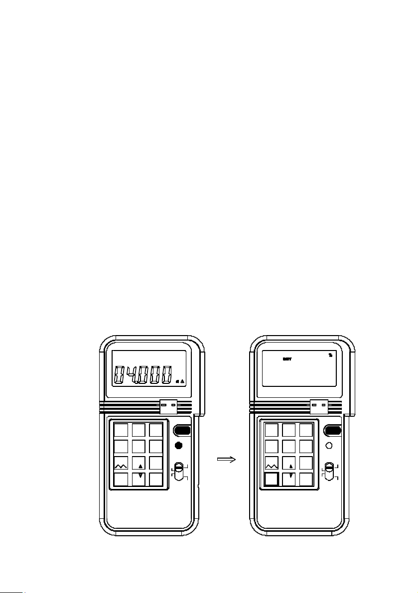
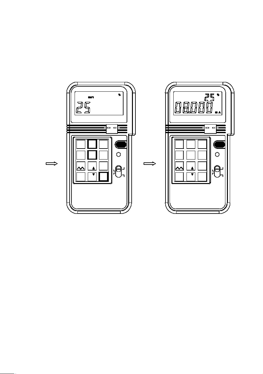
5. % input in the mA, mV, V functions
In the mA, mV, or V function, users can enter percentage. To enter
percentage (%)
1. Users press the shift button first, then SHIFT symbol will be
displayed in the LCD.
2 Press % button first, then press the number (no decimal number,
the % resolution is 1%).
3 After percentage is entered, the percentage will be displayed in
the upper LCD, and the corresponding value will be displayed in
the lower LCD.
4. The corresponding value is calculated based upon the range
selected.
4-20mA: 1% = 0.16mA
0-20mA: 1% = 0.2mA
0-24mA: 1% = 0.24mA
0-100mV: 1% = 1mV
0-1V: 1% = 0.01V
0-12V: 1% = 0.12V
5. To exit the percentage-input mode, press the SHIFT button
again.
6. After the SHIFT button is pressed, the upper LCD will become
blank, while the lower LCD retains its last value.
25%
2
¢X5¢X C F
%
%
0-24mA
K J E T
8
ENTER
0
4-20mA10-20mA
4
mV 1V
12V
7
¡D
_
%
PROCESS
CALIBRATOR
+-
TC
ON/OFF
3
SHIFT
6
V mA
9
mV
Hz
C¢X
F¢X
1 2
4-20mA
4
mV 1V
12V
7 8
_
¡D
%
0-20mA
C F¢X
%
%
5
¢X
0
0-24mA
K J E T
ENTER
+
-
TC
ON/OFF
3
SHIFT
6
V
9
mA
mV
Hz
¢XC
¢XF
PROCESS
CALIBRATOR
19
Page 23
4-20mA
mV 1V
12V
7
¡D
%
-
+
TC
1
2
0-20mA
4
C F¢X5¢X
8
_
%
0
0-24mA
K J E T
ENTER
ON/OFF
3
SHIFT
6
9
mAV
Hz
¢X
C
¢X
F
1 2
4-20mA
4
mV 1V
12V
7 8
¡D
_ %
%
0-20mA
-
+
TC
ON/OFF
3
0-24mA
K J E T
ENTER
SHIFT
6
V
9
mA
mV
Hz
¢XC
¢XF
5
¢X C F
¢X
%mV%
0
PROCESS
CALIBRATOR
PROCESS
CALIBRATOR
20
Page 24
6. Easy Step in the mA, mV, and V Functions
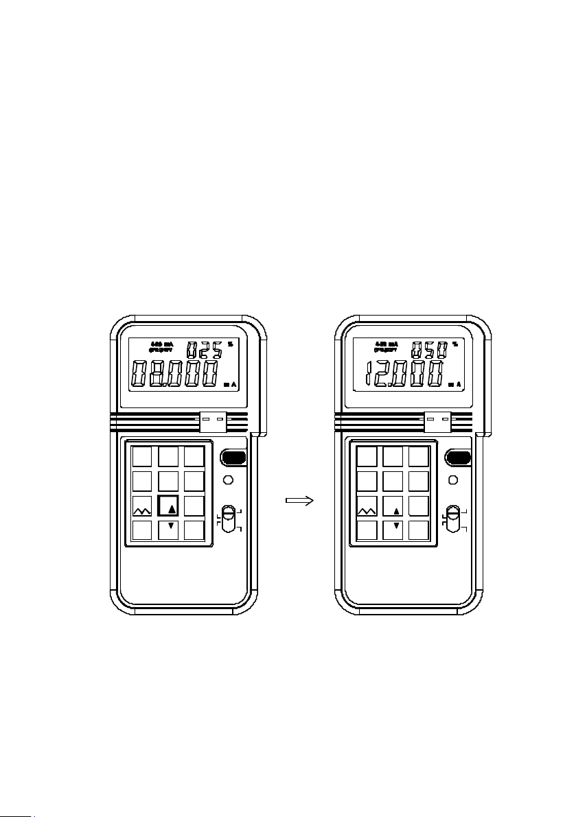
While the percentage is entered and calibrator is still in the SHIFT mode,
users can step up or down by the percentage entered. The maximum
percentage is 100% while the minimum percentage is 0%. If the next
step up or down exceeds the maximum or minimum percentage, the
percentage will stay in the previous step.
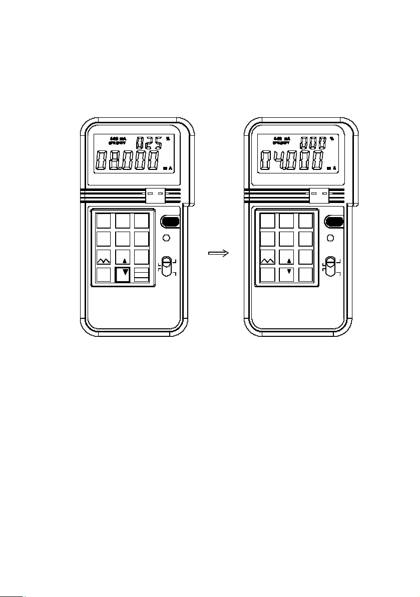
Example 1: Step Up and Down(25%):
25% -> 50% -> 75% -> 100% -> 75% -> 50% -> 25% -> 0% -> 25%
Example 2: Step Up and Down(30%):
30% -> 60% -> 90% -> 60% -> 30% -> 0% -> 30%
2
¢X5¢X C F
%
%
0-24mA
K J E T
8
ENTER
0
4-20mA10-20mA
4
mV 1V
12V
7
¡D
_
%
PROCESS
CALIBRATOR
+-
TC
ON/OFF
3
SHIFT
6
V mA
9
mV
Hz
C
¢X
F¢X
1 2
4-20mA
4
mV 1V
12V
7 8
¡D
_ %
%
0-20mA
5
C F¢X
%
0
¢X
0-24mA
K J E T
ENTER
+
-
TC
ON/OFF
3
SHIFT
6
V
9
mA
mV
Hz
C
¢X
¢XF
PROCESS
CALIBRATOR
21
Page 25
4-20mA
mV 1V
12V
¡D
%
4
7
_
0-20mA 0-24mA
5 6
¢X C F¢X K J E T
8
9
%
%
ENTER
0
-
TC
+
ON/OFF
SHIFT
mV
Hz
1 2 331 2
0-20mA
4-20mA
4
mV 1V
¢X
12V
mAV
C
¢X
F¢X
7 8
¡D
_ %
%
%
-
+
TC
ON/OFF
0-24mA
6
K J E T
9
ENTER
SHIFT
VmVmA
Hz
C
¢X
¢XF
5
¢X C F
0
PROCESS
CALIBRATOR
PROCESS
CALIBRATOR
22
Page 26
7. Auto Ramp in the mA, mV, and V functions
1% per STEP
100
%
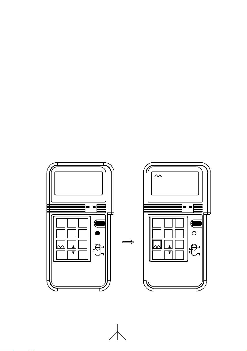
In the mA, mV, and V function, auto ramp function is available to the
users. To start the ramp function:
1. Press the SHIFT button to enter the SHIFT mode.
2. Press the NUMBER 7 key to start
3. Ramp function increment from 0% to 100%, then decrements
from 100% to 0% repeatedly. The resolution of each step is 1%
(with respect the range selected) at an interval of 0.08 seconds.
So it takes 8 seconds to ramp from 0 to 100%.
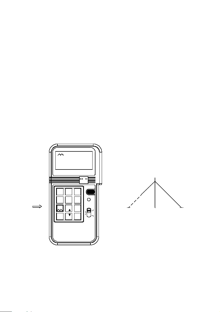
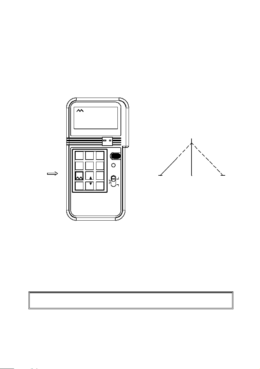
4. To temporarily stop the ramp function, press the NUMBER 7 key,
and the output will stay at the value when the NUMBER 7 key is
pressed. These features will facilitate the checking of trigger point
of tested device, such as valve controller.
5. To restart again, press the NUMBER 7 button again.
6. To return to the regular output mode, press the SHIFT button
again when ramp function is stopped.
SHIFT
1
4-20mA20-20mA
4
mV 1V
12V
7
¡D
_ %
%
3
0-24mA
K J E T
C F¢X5¢X
8
9
%
ENTER
0
PROCESS
CALIBRATOR
- +
TC
ON/OFF
SHIFT
6
V
mA
mV
Hz
C
¢X
¢XF
4-20mA
mV 1V
12V
¡D
%
4
7
21
0-20mA30-24mA
5
¢X C F
¢X
8
%
%_
0
K J E T
ENTER
+
-
TC
ON/OFF
SHIFT
6
V
9
mA
mV
Hz
C
¢X
F¢X
PROCESS
CALIBRATOR
23
Page 27
1
2 3
4-20mA
mV 1V
4
5 6
¢X C F¢X K J E T
12V
7
8
%
_¡D
%
0 ¢X
%
0-24mA0-20mA
ENTER
PROCESS
CALIBRATOR
-
+
TC
ON/OFF
SHIFT
V mA
9
mV
Hz
C
¢XF
24
Page 28
- +
TC
0-24mA
K J E T¢X C F¢X
ENTER
ON/OFF
3
SHIFT
6
VmVmA
9
Hz
C
¢X
¢XF
1
4-20mA
4
mV 1V
12V
7
¡D_ %
%
0-20mA
%
2
5
8
0
PROCESS
CALIBRATOR
Note: Do not press any button while the calibrator is performing the
ramp function (except NUMBER 7 button to stop the ramp function).
25
Page 29
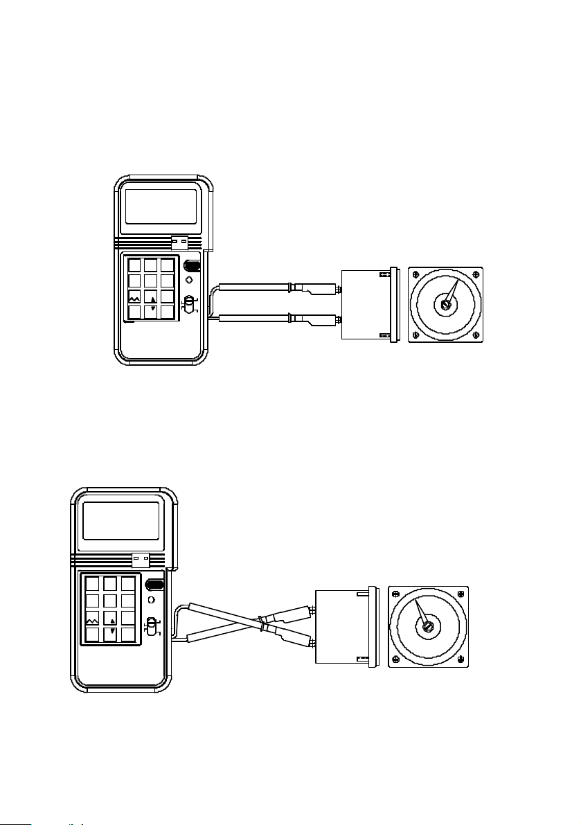
8. How to Get Negative Output
If negative output (mA, mV, or V) is needed, users can achieve it by
interchange the connection of test leads.
-
+
TC
1 2
4-20mA
4
mV 1V
12V
7
_¡D
%
PROCESS
CALIBRATOR
ON/OFF
3
0-24mA
0-20mA
SHIFT
5
6
¢X
C F
K J E T
¢X
8
V
9
%
mV
%
Hz
ENTER
0
RED
mA
C¢X
F¢X
BLACK
+
-
0
50mV
1
2
0-20mA
4-20mA
4
5
mV 1V
¢X
C F
¢X
12V
7
8
%
¡D
_
%
%
0
PROCESS
CALIBRATOR
0-24mA
K J E T
ENTER
-
+
TC
ON/OFF
3
SHIFT
6
9
RED
V
mA
mV
Hz
C¢X
F¢X
BLACK
+
-
-50mV
0
26
Page 30
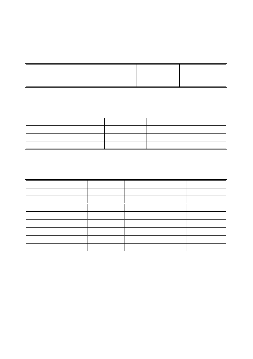
III. Electrical Specification (23? ± 5? , 5 minutes after power is on)
mA DC Current (1KΩ Max. Load, 24V Loop Supply)
Range Resolution Accuracy
4 - 20mA, 0 - 20mA, 0 -24 mA
Beeper warning when output is open and specified current output > 1mA
mV, V DC Voltage (1mA Supply Current)
Range Resolution Accuracy
0 - 100.00mV 10µV ± 0.05% ± 30µV
0 - 10.000V 1mV ± 0.05% ± 3mV
0 - 1.0000V 100µV ± 0.05% ± 300µV
Beeper warning when output is short and specified voltage output > 10mV
K, J, S, T type Thermocouples( 1? ,1? Resolution,1K Ω load Min. )
Range Accuracy Range Accuracy
K: -200 to 0? ± 1.1? K: -328 to 32? ± 2.0?
K: 0 to 1370? ± 0.8?
J: -100 to 0? ± 0.9? J: -148 to 32? ± 1.6?
J: 0 to 760 ? ± 0.7?
S: 0 to 250? ± 1.4? S: 32 to 482? ± 2.2?
S: 250 to 1760? ± 1.0?
T: -200 to 0? ± 1.0? T: -328 to 32? ± 1.8?
T: 0 to 400? ± 0.8?
K: 32 to 2400? ± 1.5?
J: 32 to 1400? ± 1.2?
S: 482 to 3200? ± 1.8?
T: 32 to 752? ± 1.5?
1µA
± 0.025%
±3µA
27
Page 31

Frequency (1 - 125Hz , 1KΩ Load Min.)
Range Resolution Accuracy
1 - 125 Hz 1 Hz ± 0.04Hz
Available Frequencies
(126 - 62500Hz, Accuracy ± 0.01% ± 0.04Hz, 1KΩ Load Min):
126.00 127.03 128.07 129.13 130.20 131.30 132.41 133.54
134.12 135.28 136.46 137.06 138.27 139.50 140.13 141.40
142.04 143.34 144.00 145.34 146.02 147.40 148.10 149.52
150.24 151.69 152.43 153.18 154.70 155.47 156.25 157.03
158.62 159.43 160.25 161.08 162.76 163.61 164.47 165.34
166.22 167.11 168.01 169.83 170.76 171.70 172.65 173.61
174.58 175.56 176.55 177.55 178.57 179.59 180.63 181.68
182.74 183.82 184.91 186.01 187.12 188.25 189.39 190.54
191.71 192.90 194.09 195.31 196.54 197.78 199.04 200.32
201.61 202.92 204.24 205.59 206.95 208.33 209.73 211.14
212.58 214.04 215.51 217.01 218.53 220.07 221.63 223.21
224.82 226.44 228.10 229.77 231.48 233.20 234.96 236.74
238.54 240.38 242.24 244.14 246.06 248.01 250.00 252.01
254.06 256.14 258.26 260.41 262.60 264.83 267.09 269.39
271.73 274.12 276.54 279.01 281.53 284.09 286.69 289.35
292.05 294.81 297.61 300.48 303.39 306.37 309.40 312.50
315.65 318.87 322.16 325.52 328.94 332.44 336.02 339.67
343.40 347.22 351.12 355.11 359.19 363.37 367.64 372.02
376.50 381.09 385.80 390.62 395.56 400.64 405.84 411.18
416.66 422.29 428.08 434.02 440.14 446.42 452.89 459.55
466.41 473.48 480.76 488.28 490.19 492.12 494.07 496.03
498.00 500.00 502.00 504.03 506.07 508.13 510.20 512.29
514.40 516.52 518.67 520.83 523.01 525.21 527.42 529.66
531.91 534.18 536.48 538.79 541.12 543.47 545.85 548.24
550.66 553.09 555.55 558.03 560.53 563.06 565.61 568.18
570.77 573.39 576.03 578.70 581.39 584.11 586.85 589.62
592.41 595.23 598.08 600.96 603.86 606.79 609.75 612.74
615.76 618.81 621.89 625.00 628.14 631.31 634.51 637.75
641.02 644.32 647.66 651.04 654.45 657.89 661.37 664.89
668.44 672.04 675.67 679.34 683.06 686.81 690.60 694.44
698.32 702.24 706.21 710.22 714.28 718.39 722.54 726.74
730.99 735.29 739.64 744.04 748.50 753.01 757.57 762.19
766.87 771.60 776.39 781.25 786.16 791.13 796.17 801.28
28
Page 32

806.45 811.68 816.99 822.36 827.81 833.33 838.92 844.59
850.34 856.16 862.06 868.05 874.12 880.28 886.52 892.85
899.28 905.79 912.40 919.11 925.92 932.83 939.84 946.96
954.19 961.53 968.99 976.56 984.25 992.06
1000.00 1008.06 1016.26 1024.59 1033.05 1041.66 1050.42 1059.32
1068.37 1077.58 1086.95 1096.49 1106.19 1116.07 1126.12 1136.36
1146.78 1157.40 1168.22 1179.24 1190.47 1201.92 1213.59 1225.49
1237.62 1250.00 1262.62 1275.51 1288.65 1302.08 1315.78 1329.78
1344.08 1358.69 1373.62 1388.88 1404.49 1420.45 1436.78 1453.48
1470.58 1488.09 1506.02 1524.39 1543.20 1562.50 1582.27 1602.56
1623.37 1644.73 1666.66 1689.18 1712.32 1736.11 1760.56 1785.71
1811.59 1838.23 1865.67 1893.93 1923.07 1953.12 1960.78 1968.50
1976.28 1984.12 1992.03 2000.00 2008.03 2016.12 2024.29 2032.52
2040.81 2049.18 2057.61 2066.11 2074.68 2083.33 2092.05 2100.84
2109.70 2118.64 2127.65 2136.75 2145.92 2155.17 2164.50 2173.91
2183.40 2192.98 2202.64 2212.38 2222.22 2232.14 2242.15 2252.25
2262.44 2272.72 2283.10 2293.57 2304.14 2314.81 2325.58 2336.44
2347.41 2358.49 2369.66 2380.95 2392.34 2403.84 2415.45 2427.18
2439.02 2450.98 2463.05 2475.24 2487.56 2500.00 2512.56 2525.25
2538.07 2551.02 2564.10 2577.31 2590.67 2604.16 2617.80 2631.57
2645.50 2659.57 2673.79 2688.17 2702.70 2717.39 2732.24 2747.25
2762.43 2777.77 2793.29 2808.98 2824.85 2840.90 2857.14 2873.56
2890.17 2906.97 2923.97 2941.17 2958.57 2976.19 2994.01 3012.04
3030.30 3048.78 3067.48 3086.41 3105.59 3125.00 3144.65 3164.55
3184.71 3205.12 3225.80 3246.75 3267.97 3289.47 3311.25 3333.33
3355.70 3378.37 3401.36 3424.65 3448.27 3472.22 3496.50 3521.12
3546.09 3571.42 3597.12 3623.18 3649.63 3676.47 3703.70 3731.34
3759.39 3787.87 3816.79 3846.15 3875.96 3906.25 3937.00 3968.25
4000.00 4032.25 4065.04 4098.36 4132.23 4166.66 4201.68 4237.28
4273.50 4310.34 4347.82 4385.96 4424.77 4464.28 4504.50 4545.45
4587.15 4629.62 4672.89 4716.98 4761.90 4807.69 4854.36 4901.96
4950.49 5000.00 5050.50 5102.04 5154.63 5208.33 5263.15 5319.14
5376.34 5434.78 5494.50 5555.55 5617.97 5681.81 5747.12 5813.95
5882.35 5952.38 6024.09 6097.56 6172.83 6250.00 6329.11 6410.25
6493.50 6578.94 6666.66 6756.75 6849.31 6944.44 7042.25 7142.85
7246.37 7352.94 7462.68 7575.75 7692.30 7812.50 7936.50 8064.51
8196.72 8333.33 8474.57 8620.68 8771.92 8928.57 9090.90 9259.25
9433.96 9615.38 9803.92
10000.00 10204.08 10416.66 10638.29 10869.56 11111.11 11363.63
11627.90 11904.76 12195.12 12500.00 12820.51 13157.89 13513.51
13888.88 14285.71 14705.88 15151.51 15625.00 16129.03 16666.66
17241.37 17857.14 18518.51 19230.76 20000.00 20833.33 21739.13
22727.27 23809.52 25000.00 26315.78 27777.77 29411.76 31250.00
29
Page 33

33333.33 35714.28 38461.53 41666.66 45454.54 50000.00 55555.55
62500.00
30
Page 34

General Specification:
Battery Type: 9V Alkaline Battery
Power Consumption: 60mA - 180mA (depends on output)
Display: 4 and 5 Digits
Operating Temperature: 0 to 50 °C ( 32 to 122 °F)
Operating Humidity: Less than 85% relative
Storage Temperature: -20 to 60° C (-4 to 140 °F)
Storage Humidity: Less than 85% relative
Dimension: 88 x 168 x 26 mm
(3.46" x 6.61" x 1.03")
Weight: 330 g / 11.63 oz
Accessories: Carrying case x 1
Users Manual x 1
K type thermocouple connector
External Battery Pack
6 1.5V AA Batteries
9 V battery x 1
Alligator clip x 1
31
Page 35
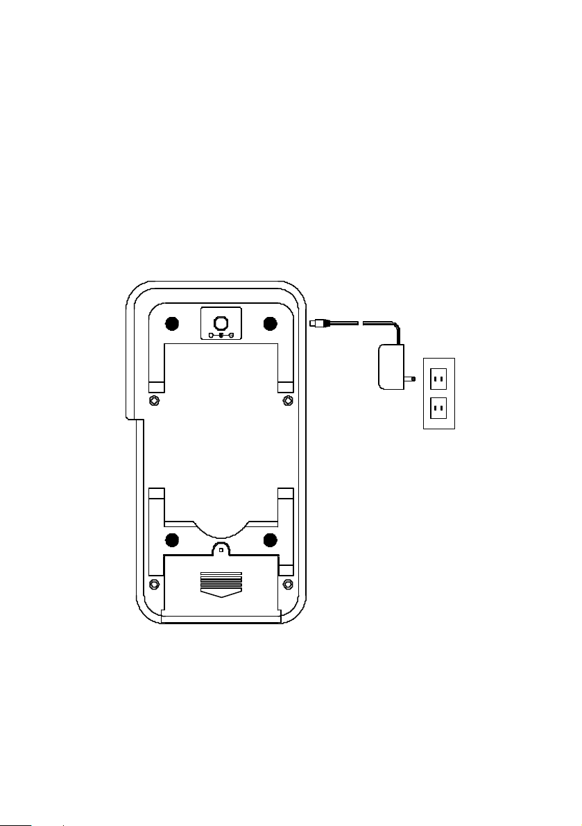
IV. Use the AC adapter
If long term usage of the calibrator is required, AC adapter can be used.
The 12V AC terminal is located in the back of the calibrator. The voltage
should be regulated between 9 to 15V.
DC 12V
-
DC 12V
+
32
Page 36
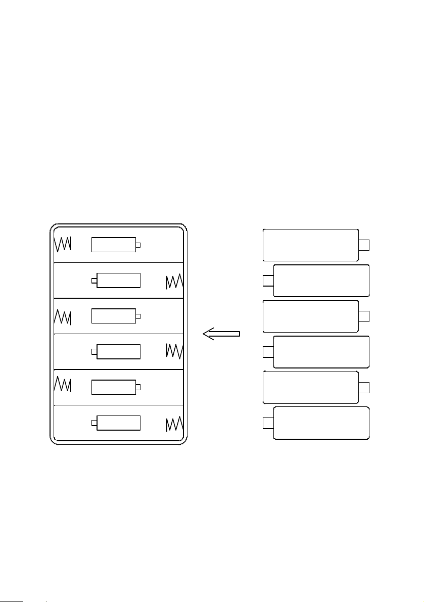
V. Use External Battery Pack
An external battery pack is included for a longer period usage. The
external battery pack needs to be packed with 6 pieces of 1.5 volts AA
batteries. To use the external battery pack, plug into the AC terminals
located in the back of the calibrator.
BATTERIES
BATTERY HOLDER
6x1.5V AA
-
+
-
+
-
+
+
-
+
-
+
-
33
Page 37
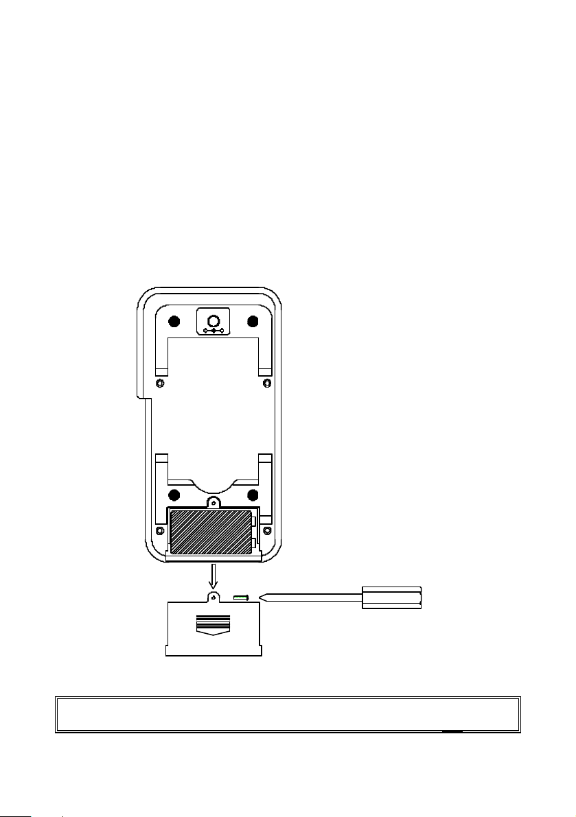
VI. Battery Replacement
When the low battery symbol is displayed on LCD, follow the following
procedures to replace the battery.
1 Turn off the calibrator by pushing the On/Off button.
2 Remove the screw of the battery compartment cover and remove the
battery compartment cover.
3 Replace the old 9V battery with a new alkaline 9V battery.
4 Replace the battery compartment cover and fasten the screw.
+-
Note: In the mA, mV, V, 0°C, and °F functions, status of low battery is
detected. While in the Hz function, status of low battery is not
34
Page 38

detected.
35
Page 39
36
Page 40
37
 Loading...