

Page 1
®
User’s Guide
omega.com
e-mail: [email protected]
For latest product manuals:
omegamanual.info
MADE IN UNITED KINGDOM
CL1201
Dry-Block Calibrator
Page 2

OMEGAnet®Online Service Internet e-mail
omega.com [email protected]
Servicing North America:
U.S.A.: Omega Engineering, Inc., One Omega Drive, P.O. Box 4047
ISO 9001 Certified Stamford, CT 06907-0047 USA
Canada: 976 Bergar
Laval (Quebec), Canada H7L 5A1
Toll-Free: 1-800-826-6342 TEL: (514) 856-6928
FAX: (514) 856-6886 e-mail: [email protected]
For immediate technical or application assistance:
U.S.A. and Canada: Sales Service: 1-800-826-6342/1-800-TC-OMEGA
Customer Service: 1-800-622-2378/1-800-622-BEST
Engineering Service: 1-800-872-9436/1-800-USA-WHEN
Mexico: En Español: 001 (203) 359-7803 FAX: (001) 203-359-7807
®
®
®
Servicing Europe:
Benelux: Managed by the United Kingdom Office
Czech Republic: Frystatska 184
733 01 Karviná, Czech Republic
Toll-Free: 0800-1-66342 TEL: +420-59-6311899
FAX: +420-59-6311114 e-mail: [email protected]
France: Managed by the United Kingdom Office
Toll-Free: 0800 466 342 TEL: +33 (0) 161 37 29 00
FAX: +33 (0) 130 57 54 27 e-mail: [email protected]
Germany/Austria: Daimlerstrasse 26
D-75392 Deckenpfronn, Germany
Toll-Free: 0 800 6397678 TEL: +49 (0) 7059 9398-0
FAX: +49 (0) 7056 9398-29 e-mail: [email protected]
United Kingdom: OMEGA Engineering Ltd.
ISO 9001 Certified One Omega Drive, River Bend Technology Centre, Northbank
Irlam, Manchester M44 5BD England
Toll-Free: 0800-488-488 TEL: +44 (0)161 777-6611
FAX: +44 (0)161 777-6622 e-mail: [email protected]
It is the policy of OMEGA Engineering, Inc. to comply with all worldwide safety and EMC/EMI
regulations that apply. OMEGA is constantly pursuing certification of its products to the European New
Approach Directives. OMEGA will add the CE mark to every appropriate device upon certification.
The information contained in this document is believed to be correct, but OMEGA accepts no liability for any
errors it contains, and reserves the right to alter specifications without notice.
WARNING: These products are not designed for use in, and should not be used for, human applications.
Page 3

CONTENTS
PAGESECTION
Introduction .................................................................................................................................. 1
Safety ............................................................................................................................................ 2
Unpacking .................................................................................................................................... 3
Installation...................................................................................................................................... 4
Specifications ................................................................................................................................ 6
User Operation Set Up .................................................................................................................. 8
Controller Test Instructions ........................................................................................................ 10
Running CL1201 From A PC ...................................................................................................... 15
Troubleshooting .......................................................................................................................... 16
i
Page 4

INTRODUCTION
A ceramic tube covers the entire test area of the furnace which insulates the isothermal block and test probes
homogeneity of temperature distribution.
The isothermal block assembly is machined from a special alloy giving excellent thermal conductivity and also
stabilisation periods.
The standard insert block has 4 test holes which accept Ø8mm probes x 80mm deep for use with a reference
blocks as detailed later in this manual.
This product offers a wide temperature range and enables high-temperature calibration routines to be carried
out easily and affordably.
Typical applications are in the glass manufacturing, electrical power, automotive and material
processing industries.
If the unit is used correctly this instrument will provide
thermal devices in many applications.
The OMEGA CL1201 is designed to provide an exceptionally stable and accurate heat source from between 150
1200°C that can be used in a Calibration laboratory or a field environment. These units enable precise
and
temperature calibration of a wide range of temperature sensors and thermostats to be carried out. They offer
fast heat up times, with unrivalled accuracy and repeatability.
The OMEGA CL1201 accepts interchangeable insert blocks allowing for many sizes of probes to be calibrated.
The unit
uniformity and rapid heating rates. Heaters are semi-embedded in a vacuum formed light-weight refractory
ceramic-fibre material which form a two-part heating assembly to achieve stable and uniform temperatures
throughout the
from the high-power heater windings. The ceramic tube supports the isothermal block and assists with
resists high-temperature oxidation. This block is designed to optimize performance between sufficient mass for
good stability and uniformity and to have a low enough mass to have rapid heating and cooling rates and good
uses an R-type Thermocouple control sensor and a special heater design for optimum temperature
block.
probe typically an R type thermocouple or an SPRT. We also offer a range of other interchangeable inserts
The built in controller features a dual LED display allowing operating parameters including the
temperature, heating status, and current set-point to be reviewed. The temperature can be easily set using
the control buttons to any desired temperature within the calibrator’s specified range.
continued accurate calibration of temperature sensors and
OMEGA CL1201
display temperature as the test sensor in the block. If the unit is set to
1200°C and the display reads 1200°C and the calibration well is at
1200°C.
calibrator is designed to give the same as the actual
block
Before using the OMEGA CL1201 make sure you have read this
manual carefully.
1
Page 5

SAFETY
Operator Safety
The following definitions apply to the terms Warning and Caution: Warning identifies
actions that may damage the instrument being used.
Warnings
HIGH TEMPERATURES ARE DANGEROUS as they can cause serious burns to operators and ignite
combustible material. Users should be aware of the following to avoid personal injury:
Cautions
Users should be aware of the following to avoid damage to the instrument:
Please read this manual carefully before using the OMEGA CL1201 Calibrator. If the equipment is not used in
the
manner described in this manual the protection provided by the equipment might be impaired.
If a safety problem should be encountered then switch off the unit at the mains socket and remove the plug from
the electricity supply.
conditions and actions that may pose hazards to the user. Caution identifies conditions and
• USE CARE AND WEAR PROTECTIVE GLOVES TO PROTECT HANDS
• DO NOT use combustible substances near hot objects
• DO NOT operate the instrument in the vicinity of inflammable liquids or gases
• DO NOT operate the instrument under any structure or in a cabinet – clearance of 20cm on all sides
and 1m above the calibrator is recommended
• NEVER use any liquids or heat transfer fluids such as silicone oil paste as dangerous fumes may be
given off
• After heating test samples, remember that parts of the instrument, namely the block and any
associated accessories may be very hot.
• The ceramic materials used in furnace manufacture become electrically conductive to some extent
at high temperatures. Also, there are partially exposed heating coils in the chamber. DO NOT use any
conductive tools within the working area of the unit without isolating first.
• DO NOT use if the cooling fan in the instrument is not working correctly
• DO NOT operate if the instrument if it appears damaged or operates abnormally
• DO NOT place any liquids or heat transfer fluids such as silicone oil paste etc onto the instrument
• DO NOT use this instrument if it is excessively wet, dirty or dusty
• DO NOT interchange slim metric inserts with slim Imperial inserts as they will become jammed.
Slim Inserts are available to suit both models
• Note that the lifetime of some components can be shortened by continuous high temperature
operation
2
Page 6

Additional Notes
The OMEGA CL1201 is a precision calibration instrument designed for optimum durability and trouble free
The unit should always be carried by the handle in the upright position to prevent the insert blocks or ceramic
insulators from being dropped and damaged.
The air above the block may be over 200°C and if the probe handle limits are exceeded, the probe may be
permanently damaged.
Unpacking
When unpacking please ensure that the following have been removed from the packaging:
operation but it must be handled with care.
Test probes and the CL1201
insert block may have differing thermal expansion rates. The precision bores
are manufactured to a very close tolerance to allow for probe expansion inside the well as the block heats up.
Otherwise, the probe may become stuck in the well.
Some test probes have temperature limits so it is advisable not to exceed this temperature. Ensure that the air
temperature above the CL1201 does not exceed the probe handle’s temperature limit.
• OMEGA CL1201 Calibrator
• Calibration certificate
• Mains cable
• Software on CD
• Allen key
• Insertion extraction tool
The user is advised to keep the original packaging in case the instrument ever needs to be returned for service or
repair. Omega accepts no responsibility for damage incurred unless the unit is correctly packed and transported
in its original packaging.
3
Page 7

INSTALLATION
The instrument should be carried with the carrying handle provided. Never move or carry the instrument when
in use or connected to the mains electricity supply.
1. All CL1201 instruments are supplied with a mains power cable.
Before connecting the instrument to the mains electricity supply, check the voltage against the rating plate
2. UK ONLY: The fused plug supplied with the mains cable is fitted with a 10 Amp fuse to protect the
3. Units showing 230V, 50/60Hz on the rating plate also operate between 210 and 260V; units with 120V,
4. Plug the mains cable into the socket on the side of the instrument.
5. Place the unit on a suitable flat bench ensuring that the air inlet vents on the underside are free from
6. Switch on the instrument next to the mains supply cable entry :
Heat Supply Neon: the neon illuminates when power is being supplied to the elements
(located on the side of the unit). Please note that the unit must be earthed to ensure proper electrical safety.
Connect the mains cable to a suitable plug according to the table below. For 230V units an RCD can be used
to provide additional safety protection against fault conditions.
Connection 220/240V, 50/60Hz Supply 110V/120V Supply, 50/60Hz
Live Brown Black
Neutral Blue White
Earth Green/yellow Green
instrument and the user.
50/60Hz also operate between 100 and 130V and units marked with 100V will operate between 90 and 110V. In
all cases the heating rate will degrade by approximately 8% at the extremes of the voltage range.
obstruction.
mains switch On
mains switch
Off
Power Supply switch: when the CL1201 is connected to the electrical supply and the switch
made the neon illuminates
Replacement cable
Should the mains lead need replacement, a cable of 1.5mm
DOUBT CONSULT A QUALIFIED ELECTRICIAN.
2
of harmonized code H05VV-F should be used. IF IN
4
Page 8

Working Conditions
The OMEGA CL1201 calibrator is designed to operate under the following conditions:
•
Indoor use
•
Environmental conditions should not be excessively dusty or dirty
deteriorate outside an ambient temperature of 10°C to 30°C.
The instrument has been tested for radio frequency interference and is certified under EN61326.
• Ambient temperature range +5°C to +40°C
• Altitude to 2000m
• Relative humidity not exceeding 95%
• Mains supply fluctuations not exceeding 10%
• Pollution degree 2
Note: The control specifications are quoted at an ambient temperature of 20°C. The specification may
5
Page 9

SPECIFICATIONS
Temperature
Temperature range (min set point 10°C) 400°C to 1200°C
Temperature set point precision 0.1°C, °F, K (1° above 1000)
Display Accuracy ±3°C
Stability (in amb of 20°C) after 10-20 mins at temperature over 30 minute period
960 - 1200°C ±0.012°C 660 - 960°C ±0.017°C 420 - 660°C ±0.015°C 150 -
420°C ±0.035°C
Radial Uniformity (well to well in - standard insert A)
960 - 1200°C ±0.25°C
660 - 960°C ±0.2°C
420 - 660°C ±0.1°C
150 - 420°C ±0.03°C
Heating/Cooling Rate
Heating rate between 50°C and 1200°C 25 minutes
Cooling rate between 1200°C
and 100°C 130 minutes
Well dimensions
Diameter x length Ø34 x155mm
Insert dimensions (80mm immersion depth)
Insert A (standard - supplied with unit)
Insert B
Insert C
Ø8 x 4 off
Ø3, 4, 6 mm x 2 off each.
Ø1/8",1/4", 3/16", 5/16", 3/8"
Insert D
Insert E
Ø3/16",1/4", 3/8" x 2 off each
Ø1/4" x
6
6 off
Page 10

System
Fan cooling Automatic
Communication RS-232
Dimensions
Dimensions H x W x D 350 x 200 x 297 mm
Weight
12kg / 24lbs
Power
Main Supply 230V (±10%) 50/60Hz 1625W
Main Supply 120V (±10%) 50/60Hz 1625W
performance will vary and will not necessarily meet the above typical specifi cation at the
The
of voltage.
Fuse Rating
230V 10A
120V 16A
Standard NIST traceable cert
150, 420, 660, 960, 1200°C
extremes
7
Page 11

USER OPERATION SET UP
insert block into the well and use the threaded tool to screw it lightly into place.
sizes are available from Techne.
The well should be clear of any dirt, foreign objects, grit or grease before the insert is fi tted.
Plug the mains cable with the correct grounded mains supply into the unit.
Turn ON the power to the unit with the switch above the mains cable inlet.
The power neon is ON whenever the furnace is connected to the supply.
Then turn ON the power switch on the front panel which supplies the control circuit. The display on the controller
should illuminate and the fan start running. The controller initially goes through a short test cycle.
The display on the unit will show the current block temperature and heat or cool to the current set point.
take 25 minutes to reach the set-point temperature depending on the set point value.
Ultimate stability may take 15 to 20 minutes more of stabilisation time.
General Operating Advice
Place the unit on an even horizontal surface with clearance around the unit of 20cm on all sides and 1m above.
The area around the calibrator should be free of draught, dirt, flammable substances, etc. Carefully lower the
Then gently lower the insulation plug onto the relevant insert block. Test Probes should be of the closest diameter
possible to the selected insert while still allowing the probe to slide in and out easily. Insert to suit various probe
The heater neon will illuminate when power is applied to the heater. When the set point is entered the block may
It may take a further 10 to 20 minutes to stabilise to within ±0.5°C of the set-point.
The Heating element life is shortened by use at temperatures close to maximum. Do not leave the furnace at high
temperature when not required.
8
Page 12
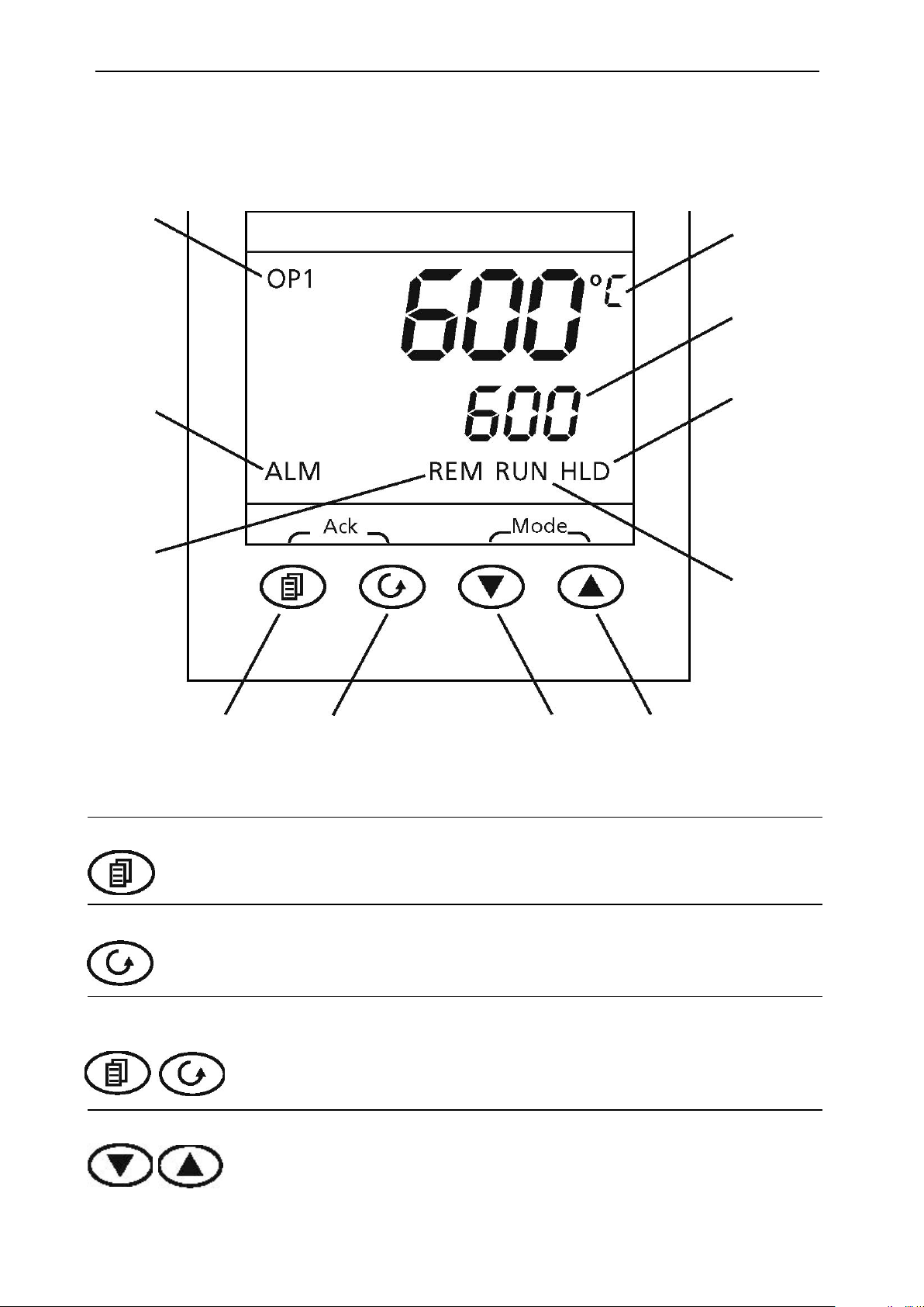
Power
Output
Indicator
Alarm
Indicator
(REM not
used)
Measured
Temperature
Set-point
Temperature
Hold
Indicator
Run
Indicator
CONTROLLER LAYOUT (HOME DISPLAY)
Keys
Page Key
Scroll
Key
ACK
Page + Scroll
Arrow Keys
Scroll Key Up Key
The Page key is used to access level 2 when held down for 3 seconds.
The Scroll key is used to scroll through the parameters.
When pressed simultaneously the ACK function is used to:
• Return
to the Home Menu.
• Acknowledge timer end.
• Acknowledge an
alarm if activated.
The arrow keys are used individually to adjust the selected parameters
and in
combination to run a program.
9
Page 13

CONTROLLER TEST INSTRUCTIONS
When switched on, the controller goes through a short test routine and then shows the measured temperature (PV =
Process Value) in the upper part of the display, and below it, the set temperature (Set Point).
Note: If a parameter is selected and no further action is taken, the display will time out and revert back to the home
display in its working level after approximately 1 minute.
The OMEGA CL1201 has been set for Operation as a Simple Controller
When switched on, the controller goes through a short test routine and then shows the measured temperature (PV =
Process Value) in the upper part of the display, and below it, the set temperature (Set Point).
Changing the Set Point
Scroll to RECNO and set to which temperature range in operation.
RECNO 5 = 1200°C
Using the Controller
The parameters in the controller are first shown by a short code (mnemonic). After 5 Seconds a description of the
returned to. In this manual the mnemonic will be shown first followed by the scrolling text in brackets;
e.g. WRK.OP <WORKING OUTPUT>
Understanding User Levels
or
UpPress
illuminate
The
has 5
section
in the top left corner of the display, indicating that the controller is calling for power (giving an output).
controller will immediately attempt to reach the set temperature and then maintain it. The temperature range
setting levels. To enter the correct control RECipe NO set in LEVEL 2 see Understanding User Levels
below.
Down
required SP.
If the SP is higher than the measured temperature, the OPI indicator will
RECNO 1 = 150°C
RECNO 2 = 450°C
RECNO 3 = 660°C
RECNO 4 = 960°C
parameter will scroll once along the display and then revert back to the mnemonic. The scrolling text can be
interrupted at any time by a single press of any of the buttons, but will not scroll again until the parameter is
There are two user levels in the controller; Level 1 (Operator) and Level 2 (Supervisor).
Level 1 (Operator) is for the day to day operation of the controller. These parameters are not protected by
a security code.
Level 2 (Supervisor) provides access to additional parameters. Access to these is protected
a security code
by
10
Page 14

To Enter Level 2
1
If the correct code is entered, the display show the level 2 home display. If an
incorrect code is entered the display reverts back to Level 1 home display
When level 2 operations have been completed, the supervisor must return to Level 1 either manually or by
‘power cycling’, there is no time out function.
To Return to Level 1
Press and hold the page Key
Press Down
selected; the display reverts to the home display at the start of the user operation section.
Table showing parameters accessible in level 1 and Level 2
Press and hold the page key
2
The display will show Leu 1 GOTO
Release the page Key
3
for 3 seconds.
4 Press
the Up
5 Press the Up
or Down
or Down
to choose LEu (Level 2)
to enter the code (Level 2 Code = 9).
to select LEu 1
It is not necessary to enter a code when going from a higher level to a lower level when level 1 is
Operator LEVEL 1 Supervisor LEVEL 2
Home display Home Display
Timer
Timer Status
Alarms (if configured)
Current Transformer Input (if configured)
Comms (if configured)
Controller setup (if configured)
Customer Calibration (if configured)
11
Page 15

Setting up the controller
Before using the controller (or during its lifetime) certain parameters may have to be set, depending on specific
requirements. To do this the controller must be set to supervisor level (Level 2).
Set Point Ramp Rate
To control the rate at which the temperature rises to sepoint, the SP.RATE function is used.
Before setting the ramp rate, it is advisable to set the setpoint to a low value, preferably 0°C. Once the ramp rate
has been set the required setpoint can be entered from the home menu. Doing so will activate the ramp rate, which
working setpoint will be shown on the lower temperature display (This is the setpoint controlled by the ramp rate).
When the process temperature has reached the setpoint value at the given ramp rate, the run indicator will turn off
cause the ramp rate to be activated and the instrument to control as described above.
NOTE: Ensure timer configuration is set to ‘none’ (Section 0) to use the setpoint ramp rate feature without any
timer functions.
To cancel the ramp rate, the SP.Rate <setpoint rate limit> must be set to OFF.
and Down
can be identified with the run indicator showing on the bottom of the display. While the ramp rate is active the
and the instrument will control at the required Setpoint temperature. Any further modifications to set point will
Press scroll
until
the display shows SP.Rate <setpoint rate limit>. Using Up
select the ramp rate required, in °C/Min.
To check the Setpoint during ramping press the Up
Units
Press scroll
select the
required
display shows units <Display Units>. Using the Up
unit
Mmemonic Description
NonE No units (Default °C)
°C Celsius
°F Fahrenheit
°K Kelvin
PErc %
and Down
and Down
once.
12
Page 16
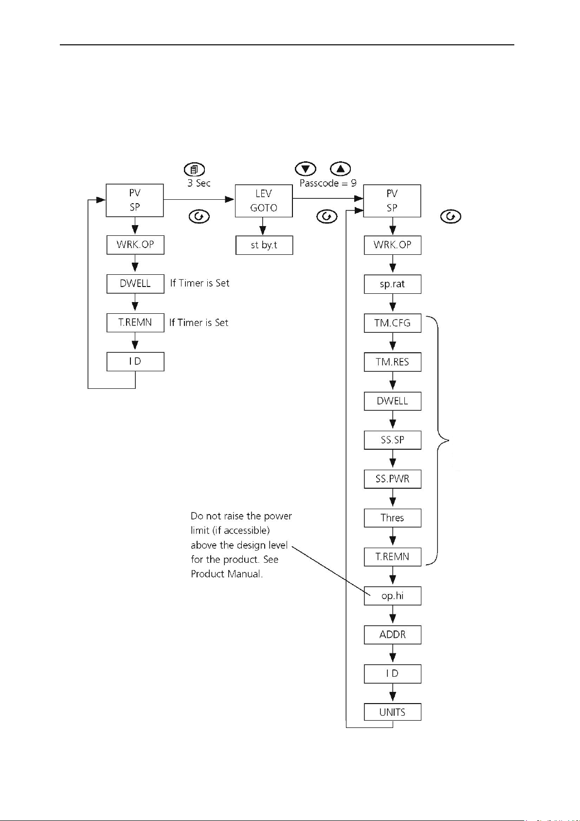
Na vigati on Diagram
3216CC
LEVEL 1
ACCESS LEVEL 2
Depending on
Timer
Configuration
13
Page 17

Controller Fault Code
Error Code Explanation Actions
Diagnostic Table
S.br Temperature sensor failure Replace the Temperature Sensor
Glossary of Terms
Process Value (PV) The actual temperature of the OMEGA CL1201. °C
Setpoint (SP) The target temperature
SP °CRamp
Rate
Control Setpoint
Element
Thermocouple
PID
Overtemperature
Overtemperature
Protection
Ramp/Dwell Pairs
Program
(O/T)
The speed at which the furnace or oven is allowed to
The temperature that can be directly set into the controller using
The heating device used in the unit.
The temperature-measuring
Proportional Integral Derivative: the control system used by the controller.
The condition which a furnace or oven may enter if part of the main control
A system to prevent the product or process being damaged if it has gone into an
overtemperature condition.
A Program is split up into segments, each segment. Contains
A sequence of stored Parameters set by the operator, which will
the OMEGA CL1201 is trying to reach.
device used in the unit
when started.
Latched Alarm Will hold the alarm condition once it has been
Non-Latching
Alarm
Will reset itself when the alarm condition is removed.
heat up or
detected.
cool down. °C/Min
the Up and
Down keys
circuit fails.
RAmp and a dwell.
a
automatically
run
Power Cycling
The Power to the controller is turned off and then back on.
14
Page 18

RUNNING THE CL1201 FROM A PC
The OMEGA CL1201 can be run from a PC using software included. This software is also available free of
charge to download from the OMEGA web siet at www.omega.com, then click on the FTP software button.
Connecting the unit to the computer using an RS-232 cable
When connecting the CL1201 to a PC for the first time using the RS-232 connection software includes
a help
file giving full instructions for use with the CL1201.
If the RS232 option is supplied, then the CL1201 is fitted with 9 way D-socket connected to the controller
communications (comms) module. The CL1201 is suitable for direct connection to a personal computer,
using a “straight through” cable as follows (the linked pins at the computer end are recommended but may not
necessary). The cable is usually 9-pin at the furnace end and 9-pin at the computer, but other alternatives are
be
shown in parentheses.
OMEGA CL1201 end of cable
female 9-pin
RS232 Cable: Tecal 1200S to PC
Computer end of cable
9-pin (25-pin) male
(25-pin)
Rx 3 (2) 3 (2) Tx
Tx 2 (3) 2 (3) Rx
Com 5 (7) 5 (7) Com
7, 8 (4, 5) Link
together
1, 4, 6 (6, 8, 20) Link
together
Comms Address
Typically the comms address is set to 1, but this can be changed.
To change the address value access the level 2 list. In level 2 press the scroll key until the ADDR
(ADDRESS) parameter is displayed. Use the Up
Down
to select the address value.
AFTER USE
When you have finished heating samples, remember that parts of the unit, inserts and associated accessories
may be very hot. Take the precautions listed earlier. We recommend that the inserts should be allowed to cool
to 100°C before being removed from the OMEGA CL1201 unit. They will still have to be handled with care.
INSERT BLOCK REMOVAL
If you need to remove an insert while it is hot, first remove the ceramic top insulator, then use the allen key
supplied to loosen the insert block and then screw the extractor tool into the threaded hole and lift the insert out
carefully.
Never leave the extractor tool in the insert while it is being used in the CL1201 unit.
The ceramic top insulator must be in place when operating the unit.
15
Page 19

Brief fault finding notes and lists of replacement parts, accessories and inserts for the CL1201 are given in this
REMOVING THE OUTER COVERS EXPOSES POTENTIALLY LETHAL MAINS VOLTAGES.
THERE ARE NO OPERATOR SERVICEABLE PARTS WITHIN THE EQUIPMENT.
Cleaning your Omega unit
Before cleaning your unit, disconnect from the power supply and allow to cool to ambient
temperature.
Do not use acetone or abrasive cleaners.
Fuses
If neither the power light nor display (on the front panel) is lit check that there is no external cause (such as a
faulty plug or lead).
Should the fuses blow persistently, a serious fault is indicated and you should return the calibrator to your
supplier for repair.
Never fit a fuse rated higher than the value indicated on the unit, serious damage or personal injury may
result.
Insulation testing
section. NOTE THAT THIS EQUIPMENT SHOULD ONLY BE DISMANTLED BY PROPERLY TRAINED
PERSONNEL.
GENERAL ADVICE/TROUBLESHOOTING
You can clean the case of the CL1201 with a cloth dipped in water or ethanol (methanol can also be used).
No part of the case or cover should be immersed in the solvents.
The OMEGA CL1201 should be connected to an HRC Fused and Isolated supply rated at 10A for 230v or 16A
for
120v.
This equipment is fitted with RFI suppression circuitry. Any check of the electrical insulation by means of high
voltage dielectric testing (for example as in BS EN 61010-1) must be carried out using only a DC voltage.
This unit contains semiconductor components which may be damaged by electric field effects.
16
Page 20

Safety Warning – Disconnection from Supply
Always ensure that the furnace is disconnected from the supply before repair work is carried out.
Safety Warning - Refractory Fibrous Insulation
This unit contains refractory fibers in its thermal insulation. These materials may be in the form of fibre
blanket or felt, vacuum formed board or shapes, mineral wool slab or loose fill fibre.
Normal use of the furnace does not result in any significant level of airborne dust from these materials, but
much higher levels may be encountered during maintenance or repair.
Whilst there is no evidence of any long term health hazards, we strongly recommend that safety
precautions are taken whenever the materials are handled.
Exposure to dust from fiber which has been used at high temperatures may cause respiratory
disease. When handling fiber always use an approved mask, eye protection, gloves and long sleeved
clothing.
Avoid breaking up waste material. Dispose of waste fiber in sealed containers. After handling
rinse exposed skin with water before washing gently with soap (not detergent). Wash work
clothing separately.
Before commencing any major repairs we recommend reference to the European Ceramic Fibre Industry
Association Bulletin No. 11 and the UK Health and Safety Executive Guidance Note EH46. We can
provide further information on request.
17
Page 21

INSERT BLOCKS Ø34 x 155mm long - Immersion Depth 80 mm Inserts are made from a specialist alloy and
alternatives bores may be ordered separately from the calibrator. Each insert is stamped for identification.
Insert Block
NUMBER PROBE DIAMETER
CL1200IB-A
CL1200IB-B
CL1200IB-C
Insert Block probe 4x Ø8.0mm (Standard insert)
Insert Block probe 2xØ3mm, 2 x Ø4mm,2 x Ø6mm
Insert Block probe Ø1/8", Ø1/4", Ø3/16", Ø5/16", Ø3/8"
CL1200IB-D Insert Block
CL1200IB-E
Block probe 6x Ø1/4"
Insert
Ceramic Top Insulator
NUMBER
CL1200CB-A
CL1200CB-B
CL1200CB-C
CL1200CB-D
CL1200CB-E
PROBE DIAMETER
Insulator A for block 4 x Ø8.0mm (Standard insert)
Insulator B for block 2 x Ø3mm, 2 x Ø4mm,2 x Ø6mm
Insulator C for block Ø1/8", Ø1/4", Ø3/16", Ø5/16", Ø3/8"
Insulator D
Insulator E for block 6 x Ø1/4"
Included with the unit
probe 2xØ3/16", 2xØ1/4", 2xØ3/8"
Included with the unit
for block 2 x Ø3/16", 2 x Ø1/4", 2 x Ø3/8"
18
Page 22

NOTES:
19
Page 23

WARRANTY/DISCLAIMER
OMEGA ENGINEERING, INC. warrants this unit to be free of defects in materials and workmanship for a
period of 37 months from date of purchase. OMEGA’s WARRANTY adds an additional one (1) month
grace period to the normal three (3) year product warranty to cover handling and shipping time. This
ensures that OMEGA’s customers receive maximum coverage on each product.
If the unit malfunctions, it must be returned to the factory for evaluation. OMEGA’s Customer Service
Department will issue an Authorized Return (AR) number immediately upon phone or written request.
Upon examination by
charge. OMEGA’s WARRANTY does not apply to defects resulting from any action of the purchaser,
including but not limited to mishandling, improper interfacing, operation outside of design limits,
improper repair, or unauthorized modification. This WARRANTY is VOID if the unit shows evidence of
having been tampered with or shows evidence of having been damaged as a result of excessive corrosion;
or current, heat, moisture or vibration; improper specification; misapplication; misuse or other operating
conditions outside of OMEGA’s control. Components in which wear is not warranted, include but are not
limited to contact points, fuses, and triacs.
OMEGA is pleased to offer suggestions on the use of
O
MEGA neither assumes responsibility for any omissions or errors nor assumes liability for any
damages that result from the use of its products in accordance with information provided by
OMEGA, either verbal or written. OMEGA warrants only that the parts manufactured by it will be
as specified and free of d efects . OMEGA MAKES NO OTHER WARRANTIES OR
REPRESENTATIONS OF ANY KIND WHATSOEVER, EXPRESS OR IMPLIED, EXCEPT THAT OF TITLE,
AND ALL IMPLIED WARRANTIES INCLUDING ANY WARRANTY OF MERCHANTABILITY AND
FI TNESS FOR A PART ICULAR PURPOSE ARE HEREBY DISCLAIMED. L IMITATI ON OF
LIABILITY: The remedies of purchaser set forth herein are exclusive, and the total liability of
OMEGA with respect to this order, whether based on contract, warranty, negligence,
indemnification, strict liability or otherwise, shall not exceed the purchase price of the
co mponen t upon wh ich liability is based. In no eve nt shall OMEGA be liable for
consequential, incidental or special damages.
CONDITIONS: Equipment sold by OMEGA is not intended to be used, nor shall it be used: (1) as a “Basic
Component” under
pplications or used on humans. Should any Product(s) be used in or with any nuclear installation or
a
activity, medical application, used on humans, or misused in any way, OMEGA assumes no responsibility
as set forth in our basic WARRANTY/ DISCLAIMER language, and, additionally, purchaser will indemnify
OMEGA and hold OMEGA harmless from any liability or damage whatsoever arising out of the use of the
Product(s) in such a manner.
OMEGA, if the unit is found to be defective, it will be repaired or replaced at no
its various products. However,
10 CFR 21 (NRC), used in or with any nuclear installation or activity; or (2) in medical
RETURN REQUESTS/INQUIRIES
Direct all warranty and repair requests/inquiries to the OMEGA Customer Service Department. BEFORE
RETURNING ANY PRODUCT(S) TO OMEGA, PURCHASER MUST OBTAIN AN AUTHORIZED RETURN
(AR) NUMB E R FR O M O M EG A’S C U S TO ME R S E RV I C E D E PART ME NT ( I N O R D ER T O AV O ID
PROCESSING DELAYS). The assigned AR number should then be marked on the outside of the return
package and on any correspondence.
The purchaser is responsible for shipping charges, freight, insurance and proper packaging to prevent
breakage in transit.
FOR WARRANTY
following information available BEFORE
contacting OMEGA:
1. Purchase Order number under which the product
was PURCHASED,
2. Model and serial number of the product under
warranty, and
3. Repair instructions and/or specific problems
relative to the product.
OMEGA’s policy is to make running changes, not model changes, whenever an improvement is possible. This affords
our customers the latest in technology and engineering.
OMEGA is a registered trademark of OMEGA ENGINEERING, INC.
© Copyright 2010 OMEGA ENGINEERING, INC. All rights reserved. This document may not be copied, photocopied,
reproduced, translated, or reduced to any electronic medium or machine-readable form, in whole or in part, without the
prior written consent of OMEGA ENGINEERING, INC.
RETURNS, please have the
FOR NON-WARRANTY REPAIRS,
for current repair charges. Have the following
information available BEFORE contacting OMEGA:
1. Purchase Order number to cover the COST
of the repair,
2. Model and serial number of the product, and
3. Repair instructions and/or specific problems
relative to the product.
consult OMEGA
Page 24

Where Do I Find Everything I Need for
Shop online at omega.com
sm
Process Measurement and Control?
OMEGA…Of Course!
TEMPERATURE
Thermocouple, RTD & Thermistor Probes, Connectors, Panels & Assemblies
Wire: Thermocouple, RTD & Thermistor
Calibrators & Ice Point References
Recorders, Controllers & Process Monitors
Infrared Pyrometers
PRESSURE, STRAIN AND FORCE
Transducers & Strain Gages
Load Cells & Pressure Gages
Displacement Transducers
Instrumentation & Accessories
FLOW/LEVEL
Rotameters, Gas Mass Flowmeters & Flow Computers
Air Velocity Indicators
Turbine/Paddlewheel Systems
Totalizers & Batch Controllers
pH/CONDUCTIVITY
pH Electrodes, Testers & Accessories
Benchtop/Laboratory Meters
Controllers, Calibrators, Simulators & Pumps
Industrial pH & Conductivity Equipment
DATA ACQUISITION
Data Acquisition & Engineering Software
Communications-Based Acquisition Systems
Plug-in Cards for Apple, IBM & Compatibles
Data Logging Systems
Recorders, Printers & Plotters
HEATERS
Heating Cable
Cartridge & Strip Heaters
Immersion & Band Heaters
Flexible Heaters
Laboratory Heaters
ENVIRONMENTAL
MONITORING AND CONTROL
Metering & Control Instrumentation
Refractometers
Pumps & Tubing
Air, Soil & Water Monitors
Industrial Water & Wastewater Treatment
pH, Conductivity & Dissolved Oxygen Instruments
M4832/0510
 Loading...