

Page 1

User’s Guide
Shop online at
omega.com
e-mail: [email protected]
For latest product manuals:
www.omegamanual.info
NORWALK, CT
SM
CL110
Precision Loop Calibrator
Page 2

omega.com [email protected]
Servicing North America:
U.S.A.
Headquarters:
Customer Service: 1-800-622-2378 (USA & Canada only)
Engineering Service: 1-800-872-9436 (USA & Canada only)
Tel: (203) 359-1660 Fax: (203) 359-7700
e-mail: [email protected]
Omega Engineering, Inc.
Toll-Free: 1-800-826-6342 (USA & Canada only)
For Other Locations Visit omega.com/worldwide
The information contained in this document is believed to be correct, but OMEGA accepts no liability for any errors it contains, and reserves
the right to alter specifications without notice.
Page 3

Introduction
The OMEGA CL110 mA (loop) calibrator is designed to be simple to
use and to offer the highest accuracy of any loop calibrator in it’s
class.
The calibrator supports the following functions:
• Current measurement and sourcing, including selectable 24V
supply
• V oltage measurement
• V alve test capability
• Selectable HART 250Ω loop resistor
• Output step and ramp
The calibrator has the following features:
• Large easy to read display for measurements and data entry
• Digit
• Interactive menus
• Input and output jacks protected by self resetting fuses
1.1 Customer Service
al knob with selectable decade control for quick and easy
data entry
providing protection to 240VAC
OMEGA Engineering
Tel: (203) 359-1660
Fax: (203) 359-7900
www.omega.com
email: [email protected]
1.2 Standard Equipment
Check to see if your calibrator is complete. It should include:
• Calibrator
• x6 AAA batteries (installed)
• T est leads
- The CL110 is supplied wit
clips installed
• Owner’s Manual
• Certified Certificate
h one set of leads with alligator
1
Page 4
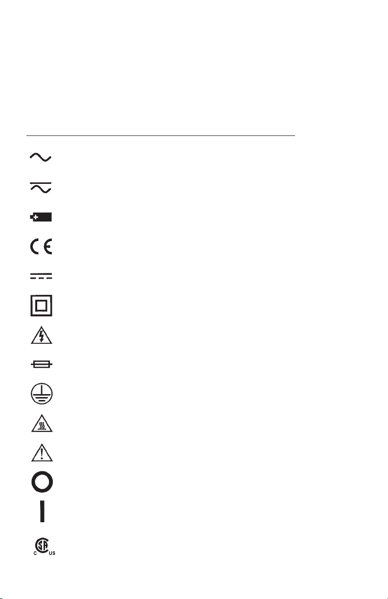
1.3 Safety information
Symbols Used
The following table lists the International Electrical Symbols. Some or
all of these symbols may be used on the instrument or in this
manual.
Symbol Description
AC (Alternating Current)
AC-DC
Battery
CE Complies with European Union Directives
DC
Double Insulated
Electric Shock
Fuse
PE Ground
Hot Surface (Burn Hazard)
Read the User’s Manual (Important Information)
Off
On
Canadian Standards Association
2
Page 5

The following definitions apply to the terms “Warning” and “Caution”.
•“Warning”identifiesconditionsandactionsthatmayposehazards
to the user.
•“Caution”identifiesconditionsandactionsthatmaydamagethe
instrument being used.
Usethecalibratoronlyasspecifiedinthismanual,otherwiseinjury
and damage to the calibrator may occur.
Warning
To avoid possible electric shock or personal injury:
•Donotapplymorethantheratedvoltage.Seespecificationsfor
supported ranges.
•Followallequipmentsafetyprocedures.
•Nevertouchtheprobetoavoltagesourcewhenthetestleadsare
plugged into the current terminals.
•Donotusethecalibratorifitisdamaged.Beforeyouusethe
calibrator, inspect the case. Look for cracks or missing plastic. Pay
particular attention to the insulation surrounding the connectors.
•Selecttheproperfunctionandrangeforyourmeasurement.
•Makesurethebatterycoverisclosedandlatchedbeforeyou
operate the calibrator.
•Removetestleadsfromthecalibratorbeforeyouopenthebattery
door.
•Inspectthetestleadsfordamagedinsulationorexposedmetal.
Check test leads continuity. Replace damaged test leads before
you use the calibrator.
•Whenusingtheprobes,keepyourfingersawayfromtheprobe
contacts. Keep your fingers behind the finger guards on the
probes.
•Connectthecommontestleadbeforeyouconnectthelivetest
lead. When you disconnect test leads, disconnect the live test lead
first.
•Donotusethecalibratorifitoperatesabnormally.Protectionmay
be impaired. When in doubt, have the calibrator serviced.
•Donotoperatethecalibratoraroundexplosivegas,vapor,ordust.
•Disconnecttestleadsbeforechangingtoanothermeasureor
source function.
3
Page 6

•Whenservicingthecalibrator,useonlyspecifiedreplacementparts.
•Toavoidfalsereadings,whichcouldleadtopossibleelectricshock
orpersonalinjury,replacethebatteryassoonasthebattery
indicator appears.
•Toavoidaviolentreleaseofpressureinapressurizedsystem,shut
off the valve and slowly bleed off the pressure before you attach
the pressure module to the pressure line.
Caution
To avoid possible damage to calibrator or to equipment under test:
•Usetheproperjacks,function,andrangeforyourmeasurementor
sourcing application.
4
Page 7
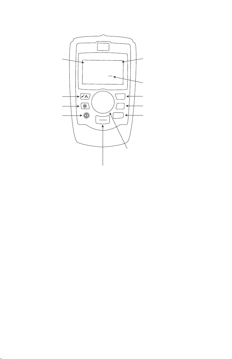
2. Calibrator Interface and Operation
Mode
Step / Ramp Enable
Backlight
On / Off
Figure 1 is typical of the main display for all operating modes. It
shows the present measurement or output value. The individual
operating modes are described below.
Use the MENU/EXIT key to display the main menu described in
section 3 to select the primary operating mode of the calibrator or to
access the calibrator setup functions.
In output mode:
•Presstheknobtomovethedecadecursor.
•Rotatetheknobtoincrementordecrementtheoutputinsteps
indicated by the selected decade.
•Usethe3percentkeystodirectlysettheoutputtopreset
values.
•Usethestep/rampkeytoselectandstoptheseadvanced
modes which are described in section 5.1.
Precision Loop
Source 0.00%
Calibrator
4.000mA
100%
25%
MENU
Menu
Press to Enter Setup Menu
Press Again to Exit
0%
EXIT
Figure 1
Simultaneous % Display
4mA = 0.00%
20mA = 100.00%
Cursor
100% Key: Sets Output to 20mA
25% Key: Steps 4, 8, 12, 16, 20mA
0% Key: Sets Output to 4mA
Digital Knob Sets Output Value
Press to Move Cursor
5
Page 8
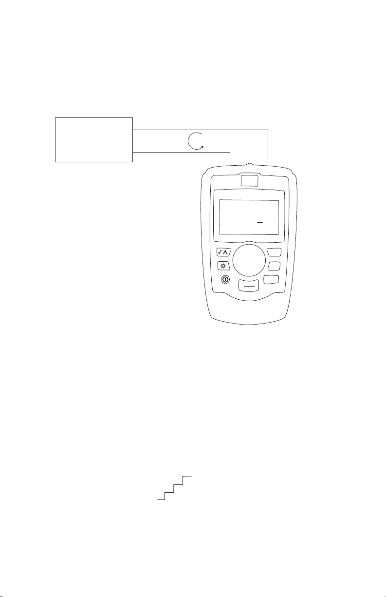
2.1 Milliamp Source
In the mA Source mode the calibrator outputs a signal from 0 to
24mA into a load of up to 1000 ohms (750 ohms if the internal HART
resistor is switched on).
Figure 2 shows the main display and typical connections for this
mode.
4-20mA INPUT DEVICE
RECORDER/INDICATOR
SCADA SYSTEM ETC.
(+)
4 to 20mA
(–)
Precision Loop
Source 0.00%
Calibrator
4.000mA
100%
25%
0%
MENU
EXIT
Figure 2
•Presstheknobtomovethedecadecursor.
•Rotatetheknobtoincrementordecrementtheoutputinsteps
indicated by the selected decade.
•Usethe3percentkeystodirectlysettheoutputtopresetvalues.
•Usethestep/rampkeytoselectandstoptheseadvancedmodes
which are described in section 5.1. When automatic step or ramp
is active one of the following is shown in the lower left corner:
Automatic step:
Automatic ramp:
6
∧
Page 9
•PressMENU/EXITtoenterthemainmenudescribedinsection3.
•Thetext‘ValveTest’isshowninthelowercenterwhenthevalve
test function has been enabled on the Setup Menu, section 4.3.
Valvetestisdescribedinmoredetailinsection5.2.
•Thetext‘250Ω’ text is shown in the lower right corner when the
HART resistor has been enabled on the Setup Menu, section 4.4.
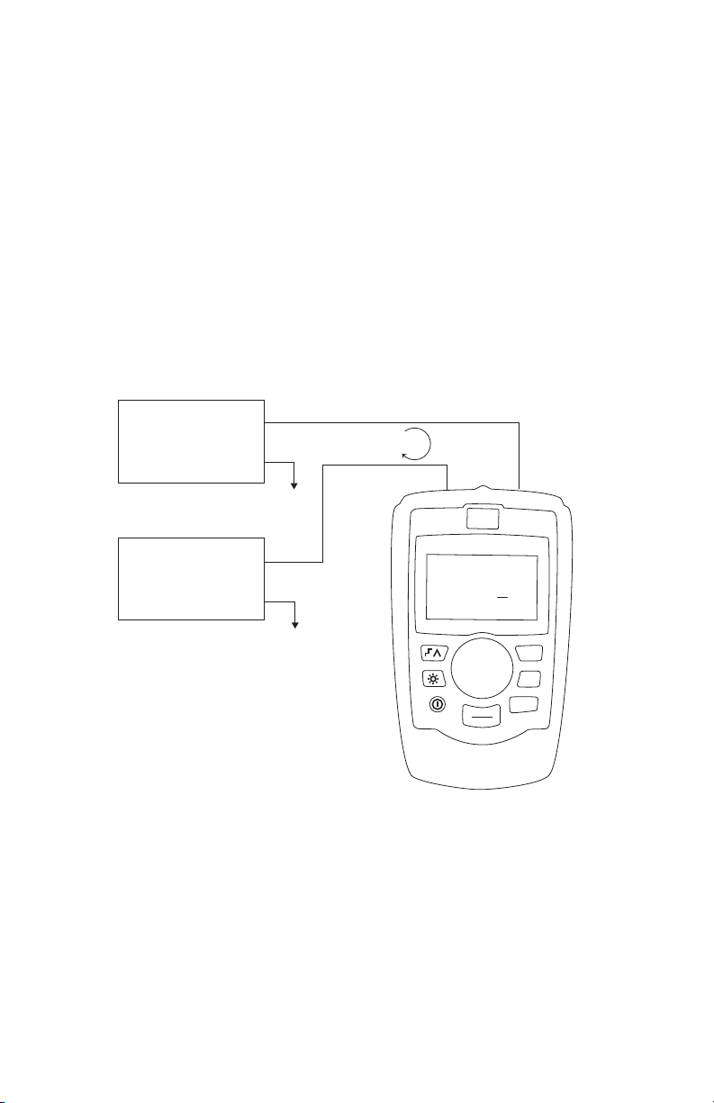
2.2 Milliamp Simulate
In the mA Simulate mode the calibrator functions like a 2-wire
transmitter by controlling the loop current from an external power
supply. This function is a great way to test a loop with the transmitter
removed.
Figure 3 shows the main display and typical connections for this
mode.
(+)
POWER SUPPLY
30 VDC MAX
(–)
(+)
4-20mA
INPUT DEVICE
(–)
4 to 20mA
Precision Loop
Simulate 0.00%
Calibrator
4.000mA
100%
25%
0%
MENU
EXIT
Figure 3
•Presstheknobtomovethedecadecursor.
•Rotatetheknobtoincrementordecrementtheoutputinsteps
indicated by the selected decade.
•Usethe3percentkeystodirectlysettheoutputtopresetvalues.
•Usethestep/rampkeytoselectandstoptheseadvancedmodes
which are described in section 5.1. When automatic step or ramp
is active one of the following is shown in the lower left corner:
7
Page 10
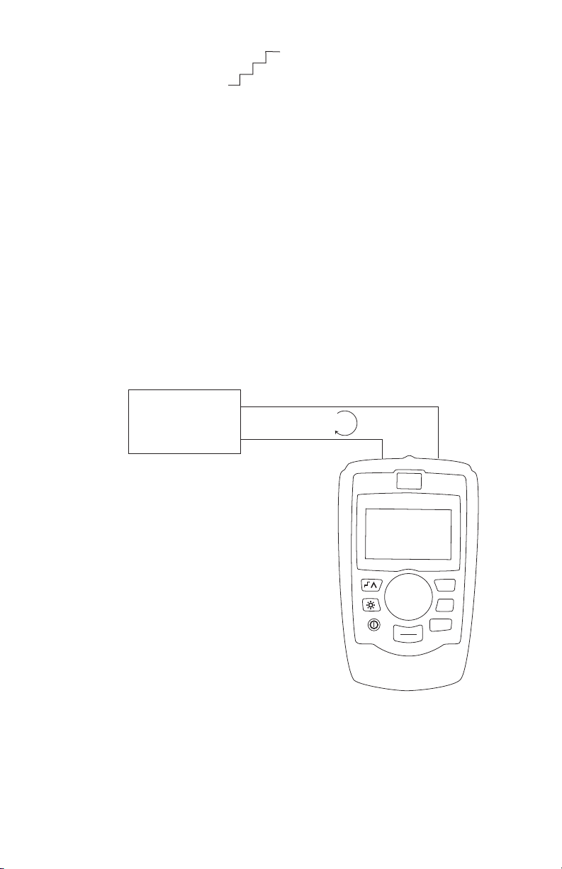
Automatic step:
Automatic ramp:
∧
•PressMENU/EXITtoenterthemainmenudescribedinsection3.
•Thetext‘ValveTest’isshowninthelowercenterwhenthevalve
test function has been enabled on the Setup Menu, section 4.3.
Valvetestisdescribedinmoredetailinsection5.2.
•Thetext‘250Ω’ text is shown in the lower right corner when the
HART resistor has been enabled on the Setup Menu, section 4.4.
2.3 Milliamp Measure without 24V power
In the mA Measure mode, the calibrator displays the loop current.
Figure 4 shows the main display and typical connections for this
mode.
(+)
4-20mA
OUTPUT DEVICE
(–)
4 to 20mA
Precision Loop
Measure 0.00%
Calibrator
4.000mA
MENU
EXIT
Figure 4
•PressMENU/EXITtoenterthemainmenudescribedinsection3.
•Thetext‘250Ω’ text is shown in the lower right corner when the
HART resistor has been enabled on the Setup Menu, section 4.4.
8
100%
25%
0%
Page 11
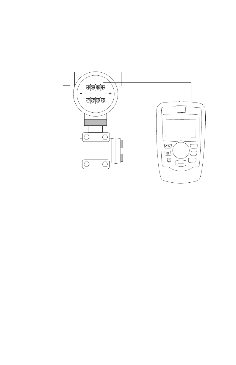
2.4 Milliamp Measure with 24V power
InthemAMeasurewith24Vmode,thecalibratoroutputs24VDC
while displaying the loop current. The mode is useful for powering a
transmitter without the need for a separate power supply.
Figure 5 shows the main display and typical connections for this
mode.
Precision Loop
Measure 24V 0.00%
Calibrator
4.000mA
MENU
EXIT
100%
25%
0%
Figure 5
•PressMENU/EXITtoenterthemainmenudescribedinsection3.
•Thetext‘250Ω’ text is shown in the lower right corner when the
HART resistor has been enabled on the Setup Menu, section 4.4.
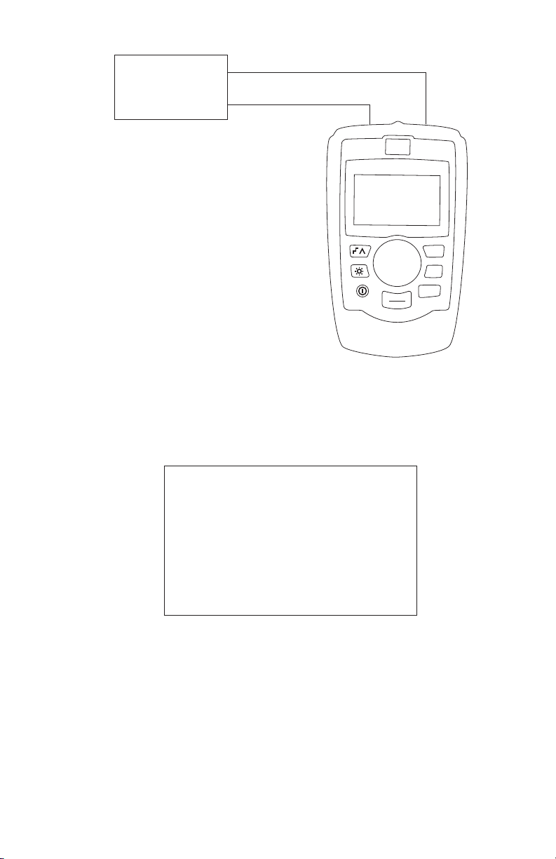
2.5 Volts Measure
IntheVoltsMeasuremode,thecalibratordisplaystheloopvoltage.
Figure 6 shows the main display and typical connections for this
mode.
•PressMENU/EXITtoenterthemainmenudescribedinsection3.
9
Page 12
(+)
VOLTAGE
OUTPUT DEVICE
(–)
Precision Loop
Measure
10.000V
MENU
EXIT
Figure 6
3. Main Menu
The Main Menu is used to select the primary operating mode of the
calibrator or to access the calibrator setup functions.
Calibrator
100%
25%
0%
mA Source
mA Simulate
mA Measure
mAMeasurewith24V
VoltsMeasure
Calibrator Setup Menu
Rotate the knob to select an action by moving the reverse video
highlight up and down. Press the knob to perform the selected
action. Press MENU/EXIT to return to the main display without
performing an action.
The first five actions change the operating mode accordingly and
return to the main display described in section 2.
The “Calibrator Setup Menu” action is described in section 4.
10
Page 13

4. Calibrator Setup Menu
The calibrator setup menu consists of two screens. The second
screenisreachedbyselecting‘OtherParameters’onthefirstscreen.
Auto Ramp Time
Auto Step Time
ValveTest
HART 250Ω Resistor
Other Parameters
mA Span
Contrast
Auto Shutdown Time
Rotate the knob to select an action by moving the reverse video
highlight up and down. Press the knob to perform the selected
action. Press MENU/EXIT to return to the main display without
performing an action.
4.1 Setting Auto Ramp Time
Auto Ramp Time
10 SEC.
Press & hold to Save
This function sets the full scale ramp time for the mA ramp feature
described in more detail in section 5.1. The value can be set from 5
to 300 seconds.
Rotatetheknobtoadjustthevalue.Pressandholdtheknobtosave
it. Press MENU/EXIT to restore the previous value and return to the
main display.
11
Page 14

4.2 Setting Auto Step Time
Auto Step Time
10 SEC.
Press & hold to Save
This function sets the step interval time for the mA Auto Step feature
described in more detail in section 5.1. The value can be set from 5
to 300 seconds.
Rotatetheknobtoadjustthevalue.Pressandholdtheknobtosave
it. Press MENU/EXIT to restore the previous value and return to the
main display.
4.3 Enabling Valve Test
Valve Test Enable
OFF ON
This function enables and disables the valve test feature described in
more detail in section 5.2.
Rotate the knob to move the reverse video highlight to the desired
selection. Press the knob to save the highlighted selection. Press
MENU/EXIT to restore the previous selection and return to the main
display.
12
Page 15

4.4 Enabling the Hart Resistor
HART Resistor Enable
OFF ON
This function enables and disables the Hart resistor described in
more detail in section 5.3.
Rotate the knob to move the reverse video highlight to the desired
selection. Press the knob to save the highlighted selection. Press
MENU/EXIT to restore the previous selection and return to the main
display.
4.5 Selecting mA Span
mA Span Selection
4 to 20 mA
0 to 20 mA
This function selects the mA span used to calculate the percent of
span field on the main display, and to set the value used by the 0%
key.
Rotate the knob to move the reverse video highlight to the desired
selection. Press the knob to save the highlighted selection. Press
MENU/EXIT to restore the previous selection and return to the main
display.
4.6 Contrast Adjustment
Contrast
Sample normal video
Sample reverse video
This function sets the display contrast.
Rotatetheknobtoadjustthecontrast.Therangeofvaluesisshown
by the bar graph, with higher contrast shown by a longer bar. The
sample normal and reverse video text lines allow evaluation of both
13
Page 16

text modes. Press the knob to save the contrast value. Press MENU/
EXIT to restore the previous selection and return to the main display.
4.7 Configuring Auto Shutdown
Auto Shutdown Time
10 MIN.
This function sets or disables the time before the unit automatically
shuts down if the keypad is not used. The value can be set to
‘Disabled’,orfrom1to30minutes.
Rotatetheknobtoadjustthevalue.Pressandholdtheknobtosave
it. Press MENU/EXIT to restore the previous value and return to the
main display.
5. Advanced Features
The calibrator has several advanced features that are available
through the Calibrator Setup Menus. How the features are enabled
and what they do is described below.
5.1 Step and Ramp Operation
The calibrator has several unique features that are helpful aids when
doing milliamp calibrations.
The percent keys allow the user to set the milliamp output to 0% of
span, 100% of span, or step it by 25% of span.
The “Step/Ramp” key allows hands free operation by automatically
stepping or ramping the milliamp output from 0% to 100% and back
continuously.
The 100% value is always 20 mA, but the 0% value may be 0 mA or 4
mA depending on the mA span setting described in section 4.5. The
25% step size is either 5 mA or 4 mA accordingly.
5.1.1 Manual Stepping
1. Use the main menu to set the calibrator to source or simulate
current.
2. Press the “0%” key to set the output to 0% of span.
3. Press the “100%” key to set the output to 100% of span.
14
Page 17

4. Press the “25%” key to step the output in 25% of span
increments, from 0% of span to 100% of span and back.
5.1.2 Automatic Stepping and Ramping
1. Use the main menu to set the calibrator to source or simulate
current.
2. The calibrator has separate Auto ramp and step times. Use the
menu system to set the ramp or step time as described in
section 4.1 or 4.2.
3. Press the “Step/Ramp” key once to continually step the output
from 0% of span to 100% of span and back in increments of 25%
of span at the specified interval.
Press the “Step/Ramp” once more to go to auto ramp.
Press one of the percent keys, or the “Step/Ramp” twice more, to
turn off the auto step and ramp.
4. Press the “Step/Ramp” key twice to continually ramp the output
from 0% of span to 100% of span over the specified interval, and
then back over the specified interval.
Press one of the percent keys, or the “Step/Ramp” once more, to
turn off the auto step and ramp.
5.2 Valve Test
The calibrator has a valve test mode for verifying proper operation of
valves. In valve test the user can step the output to the following
values: 3.8 mA, 4.0mA, 4.2mA, 8.0 mA, 12.0 mA, 16.0 mA, 19.8 mA,
20.0 mA, 20.2 mA, and back.
The valve test mA values are not affected by the mA span setting
described in section 4.5
1. Use the main menu to set the calibrator to source or simulate
current.
2. If valve test is not enabled, use the menu system to enable it as
described in section 4.3.
3. Press the “Step/Ramp” key or the “25%” key to step the output
to verify the proper valve operation.
4. Use the menu system to disable valve test when done.
5.3 Hart 250Ω Resistor
The calibrator has the ability to insert a 250Ω resistor in series with
the power supply in order to facilitate the use of a Hart
communicator. The Hart resistor is enabled through the menu
system as described in section 4.4.
15
Page 18

6. Maintenance
6.1 Replacing Batteries
Replace batteries as soon as the battery indicator turns on to avoid
false measurement. If the batteries discharge too deeply the CL110
will automatically shut down to avoid battery leakage.
Note: Use only AAA size alkaline, lithium batteries, or rechargeable
NiMh cells.
6.2 Cleaning the Unit
Warning
Toavoidpersonalinjuryordamagetothecalibrator,useonlythe
specified replacement parts and do not allow water into the case.
Caution
To avoid damaging the plastic lens and case, do not use solvents or
abrasive cleaners. Clean the calibrator with a soft cloth dampened
with water or water and mild soap.
6.3 Fuse Protection
The CL110 is protected with an internal polyfuse against overcurrent
conditions. The fuse will automatically reset, usually within a few
seconds. Do not attempt to open the unit and troubleshoot. This will
void the product warranty.
16
Page 19

7. Specifications
Functions: mA source, mA simulate, mA read, mA read/
loop power, and volts read.
Ranges: mA (0 to 24mA) and Volts (0 to 30VDC)
Resolution: 1uA on mA ranges and 1mV on voltage range
Accuracy: 0.01% +/- 2LSD all ranges (@23° +/- 5°C)
Operating Temp Range: -10°C to 55°C
Humidity Range: 10 to 95% non-condensing
Stability: 20ppm of F.S. /°C from -10°C to 18°C and 28°C
to 55°C
Display: 128 x 64 pixels, LCD Graphic w/backlight, .34”
high digits
Power: 6AAA alkaline, lithium, or NiMH batteries
Battery Life: ≥ 40 hours continuous use (measure mode)
Loop Compliance
Voltage:
Loop Drive Capability: 1200Ω without HART resistor, 950 Ω with HART
Over-Voltage
Overload Current
Protection:
EMC: EN61326 Annex A (Portable Instruments)
Dimensions (LxWxD): 6” x 3.6” x 1.3” (15 cm x 9 cm x 3 cm)
Weight: 9.5 ounces (0.3 kg)
Included Accessories: Traceable calibration certificate with data,
Protection: 240VAC
24VDC @ 20mA
resistor
28mA DC
batteries, test leads, and manual
17
Page 20

WARRANTY/DISCLAIMER
OMEGA ENGINEERING, INC. warrants this unit to be free of defects in materials and workmanship for a
period of 13 months from date of purchase. OMEGA’s WARRANTY adds an additional one (1) month grace
period to the normal one (1) year product warranty to cover handling and shipping time. This ensures
that OMEGA’s customers receive maximum coverage on each product.
If the unit malfunctions, it must be returned to the factory for evaluation. OMEGA’s Customer Service
Department will issue an Authorized Return (AR) number immediately upon phone or written request.
Upon examination by OMEGA, if the unit is found to be defective, it will be repaired or replaced at no
charge. OMEGA’s WARRANTY does not apply to defects resulting from any action of the purchaser,
including
improper repair, or unauthorized modification. This WARRANTY is VOID if the unit shows evidence of
having been tampered with or shows evidence of having been damaged as a result of excessive corrosion;
or current, heat, moisture or vibration; improper specification; misapplication; misuse or other operating
conditions outside of OMEGA’s control. Components in which wear is not warranted, include but are not
limited to contact points, fuses, and triacs.
OMEGA is pleased to offer suggesti ons on the u se of its various products. However,
OMEGA neither assumes responsibility for any omissions or errors nor assumes liability for
any damages that result from the use of its products in accordance with information provided
by OMEGA, either verbal or written. OMEGA warrants only that the parts manufactured by the
company
REPRESENTATIONS OF ANY KIND WHATSOEVER, EXPRESSED OR IMPLIED, EXCEPT THAT OF
TITLE, AND ALL IMPLIED WARRANTIES INCLUDING ANY WARRANTY OF MERCHANTABILITY
AND FITNESS FOR A PARTICULAR PURPO SE ARE HEREBY DISCLAIMED. LI MITATION OF
LIABILITY: The remedies of purchaser set forth herein are exclusive, and the total liability of
OMEGA with resp ect to this order, whether based on contract, warranty, neg ligence,
indemnification, stric t liability or otherwise, shall not exceed the purchase price of the
co mpone nt upon which li abi lity i s based. In no eve nt sh all OMEGA be lia bl e for
consequential, incidental or special damages.
CONDITIONS: Equipment sold by OMEGA is not intended to be used, nor shall it be used: (1) as a “Basic
Component”
applications or used on humans. Should any Product(s) be used in or with any nuclear installation or
activity, medical application, used on humans, or misused in any way, OMEGA assumes no responsibility
as set forth in our basic WARRANTY/DISCLAIMER language, and, additionally, purchaser will indemnify
OMEGA and hold OMEGA harmless from any liability or damage whatsoever arising out of the use of the
Product(s) in such a manner.
but not limited to mishandling, improper interfacing, operation outside of design limits,
will be as specified and free of defects. OMEGA MAKES NO OTHER WARRANTIES OR
under 10 CFR 21 (NRC), used in or with any nuclear installation or activity; or (2) in medical
Direct all warranty and repair requests/inquiries to the OMEGA Customer Service Department. BEFORE
RETURN REQUESTS/INQUIRIES
RETURNING ANY PRODUCT(S) TO OMEGA, PURCHASER MUST OBTAIN AN AUTHORIZED RETURN (AR)
NUMBER FROM OMEGA’S CUSTOMER SERVICE DEPARTMENT (IN ORDER TO AVOID PROCESSING
DELAYS). The assigned AR number should then be marked on the outside of the return package and on any
correspondence.
The purchaser is responsible for shipping charges, freight, insurance and proper packaging to prevent
breakage in transit.
FOR WARRANTY RETURNS, please have the
following information available BEFORE contacting
OMEGA:
1. Purchase Order number under which the product
was PURCHASED,
2. Model and serial number of the product under
warranty, and
3. Repair instructions and/or specific problems
relative to the product.
OMEGA’s policy is to make running changes, not model changes, whenever an improvement is possible. This affords our
customers the latest in technology and engineering.
OMEGA is a registered trademark of OMEGA ENGINEERING, INC.
© Copyright 2017 OMEGA ENGINEERING, INC. All rights reserved. T his documen t may not be copie d, photocop ied,
reproduced, translated, or reduced to any electronic medium or machine-readable form, in whole or in part, without the prior
written consent of OMEGA ENGINEERING, INC.
FOR NON-WARRANTY REPAIRS, consult
OMEGA for current repair charges. Have
the following information available BEFORE
contacting OMEGA:
1. Purchase Order number to cover the COST
of the repair,
2. Model and serial number of the product, and
3. Repair instructions and/or specific problems
relative to the product.
19
Page 21
Where Do I Find Everything I Need for
Process Measurement and Control?
OMEGA…Of Course!
Shop online at omega.com
TEMPERATURE
Thermocouple, RTD & Thermistor Probes, Connectors,
Panels & Assemblies
Wire: Thermocouple, RTD & Thermistor
Calibrators & Ice Point References
Recorders, Controllers & Process Monitors
Infrared Pyrometers
PRESSURE, STRAIN AND FORCE
Transducers & Strain Gages
Load Cells & Pressure Gages
Displacement Transducers
Instrumentation & Accessories
FLOW/LEVEL
Rotameters, Gas Mass Flowmeters & Flow Computers
Air Velocity Indicators
Turbine/Paddlewheel Systems
Totalizers & Batch Controllers
pH/CONDUCTIVITY
pH Electrodes, Testers & Accessories
Benchtop/Laboratory Meters
Controllers, Calibrators, Simulators & Pumps
Industrial pH & Conductivity Equipment
SM
DATA ACQUISITION
Communications-Based Acquisition Systems
Data Logging Systems
Wireless Sensors, Transmitters, & Receivers
Signal Conditioners
Data Acquisition Software
HEATERS
Heating Cable
Cartridge & Strip Heaters
Immersion & Band Heaters
Flexible Heaters
Laboratory Heaters
ENVIRONMENTAL
MONITORING AND CONTROL
Metering & Control Instrumentation
Refractometers
Pumps & Tubing
Air, Soil & Water Monitors
Industrial Water & Wastewater Treatment
pH, Conductivity & Dissolved Oxygen Instruments
M5295/0217
 Loading...