

Page 1
Page 2

Page 3
Table of Contents
Page 4

I. PANEL DESCRIPTION ....................................................................................... 1
II. OPERATING INSTRUCTION........................................................................... 7
1. MA OUTPUT ......................................................................................................... 7
1A. GENERAL OPERATION 4 - 20MA ........................................................................ 7
1B. SELECT 0 - 20MA OR 0 - 24MA.......................................................................... 8
1C. ENTER A VALUE LESS THAN 1 ............................................................................. 9
2. % (PERCENTAGE) INPUT ....................................................................................... 9
3. EASY STEP UP AND DOWN ..................................................................................11
4. AUTO STEP FUNCTION: .......................................................................................13
5. AUTO RAMP FUNCTION.......................................................................................15
6. 0 TO 24 V OUTPUT ..............................................................................................17
III. ELECTRICAL SPECIFICATION (23°C ± 5°C)............................................18
IV. USE THE AC ADAPTER ..................................................................................19
V. USE EXTERNAL BATTERY PACK.................................................................19
VI. BATTERY REPLACEMENT...........................................................................20
Page 5
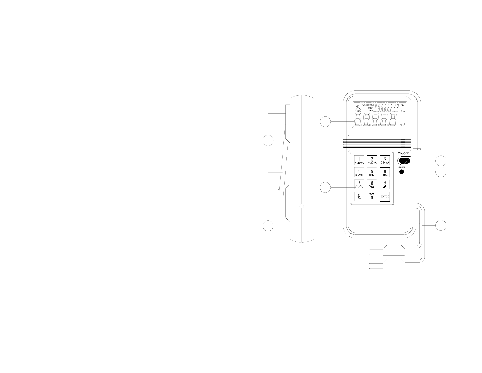
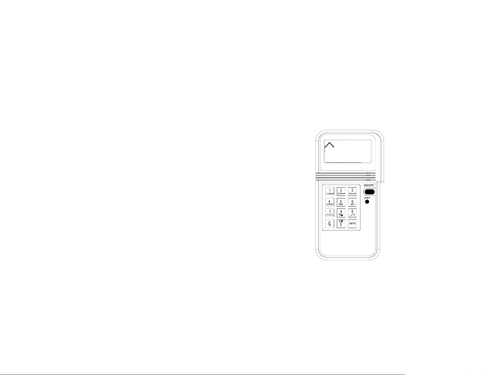
I. Panel Description
7
1
2
3
5
6
1. LCD DISPLAY 5. NUMERICAL & FUNCTION KEYPAD
2. ON/OFF BUTTON 6. STAND
3. SHIFT BUTTON 7. AC ADAPTOR INPUT SOCKET
4. OUTPUT LEADS
1
4
Page 6
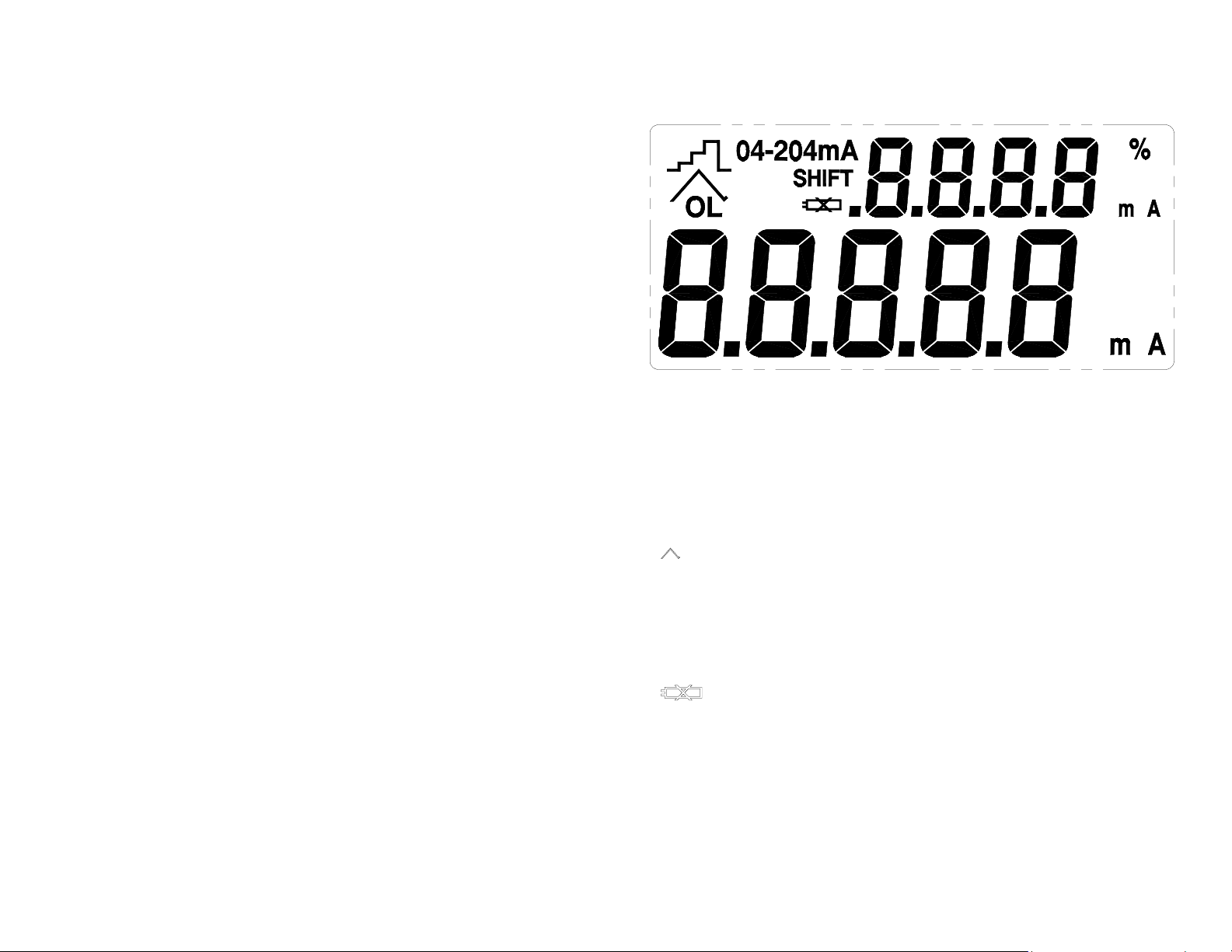
1. mA: Units
2. 04-204mA : Range of mA
3. %: Percentage
4. : Ramp
5. :STEP
6. OL: Overload, output open
7. SHIFT: Select SHIFT functions
8. : Battery low
2
Page 7
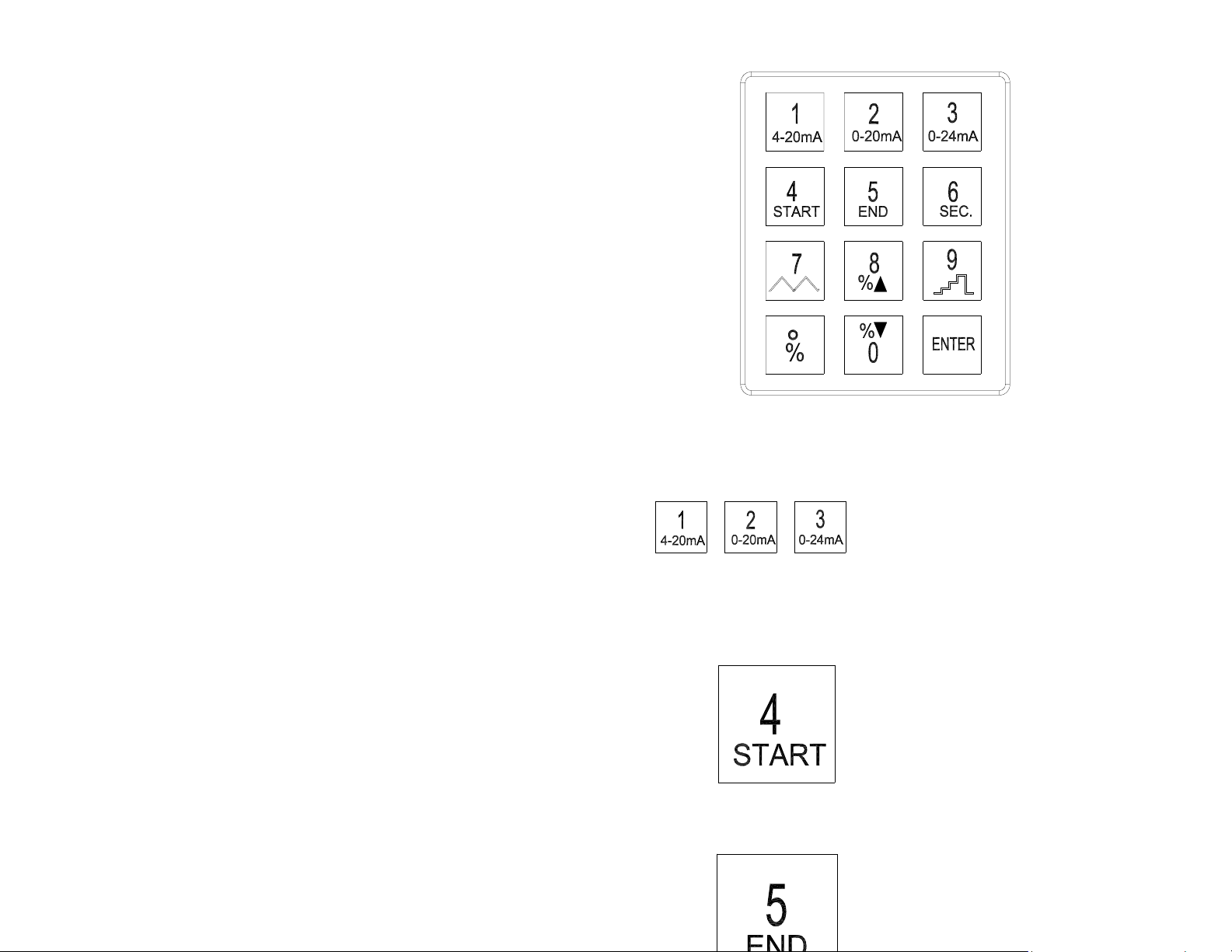
1
1.
Press SHIFT button, and then press one of these three buttons to select
desired mA range
2.
Press SHIFT button, then press this button to enter the START value for auto
ramp function
3.
3
Page 8
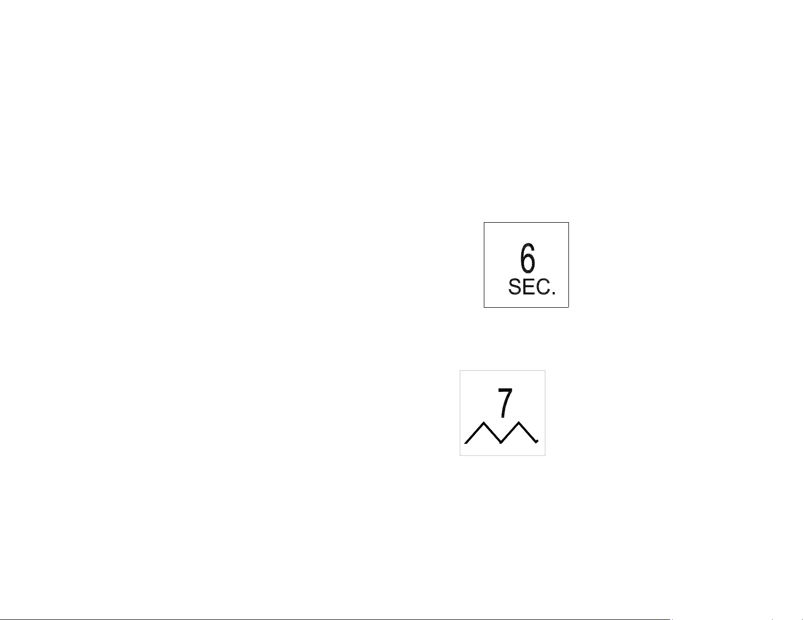
Press SHIFT button, then press this button to enter END value for auto ramp
function
4.
Press SHIFT button, then press this button to enter duration in SECONDS for
auto ramp function.
5.
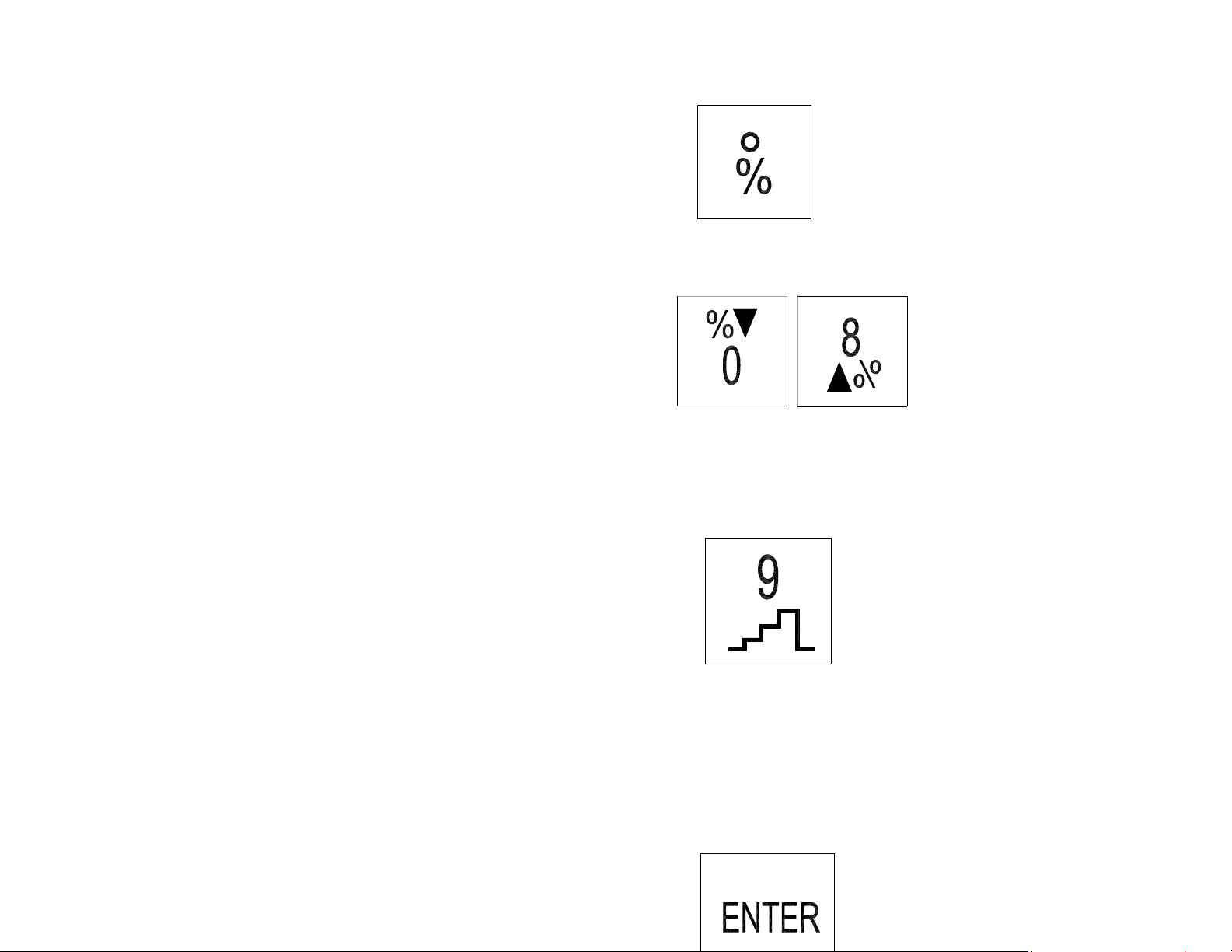
Press SHIFT button, then press this button to perform auto-ramp function. To
stop the auto-ramp function, press this button again
4
Page 9
6.
Press SHIFT button, then press this button first to enter percentage (0 –100)
7.
While the calibrator is in the SHIFT mode, and the percentage is entered,
press these buttons to increment or decrement %.
8.
Press this button to start auto STEP function. To temporarily stop STEP
function, press this button again.
9.
5
Page 10

Always press this button to complete the entry of numbers.
6
Page 11
II. Operating Instruction
1. mA Output
1a. General Operation 4 - 20mA
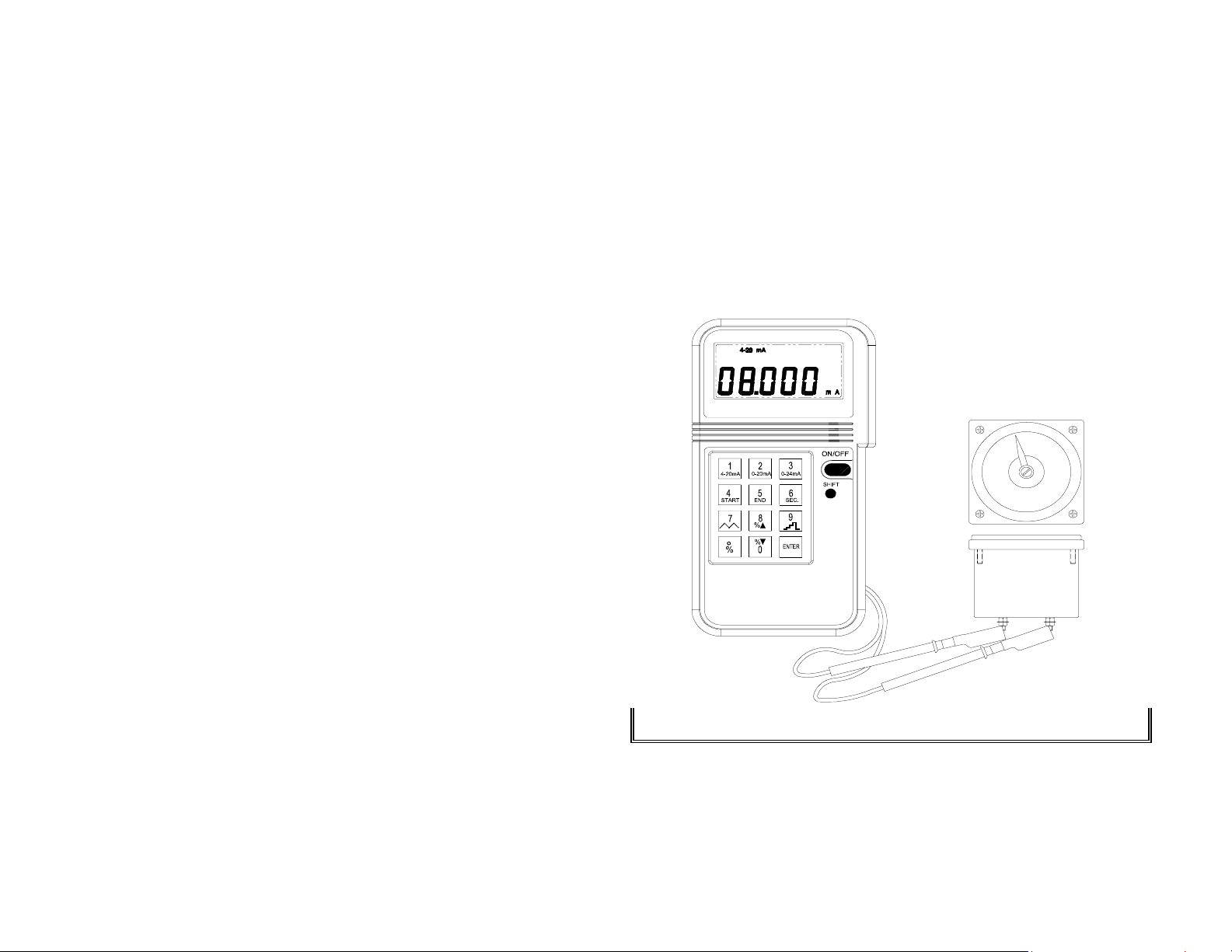
1 Turn the power on, and wait until the STBY symbol disappears
(about 1 min.)
2 Plug the test leads into the output connectors of calibrator
accordingly (Black to black, red to red). Attach alligator clip if
necessary.
3 Press the keypad (including the decimal point) to enter the value of
mA directly.
4 Using the test leads or alligator clips, touch or clip on the terminals
to be calibrated.
8.000mA
Note: Maximum 5 digits can be entered. If users enter less than 5 digits
(1 to 4 digits), users must press ENTER button to indicate the end of
entry. If users enter 5 or more digits, calibrator will automatically end the
entry and output specified value current.
7
Page 12
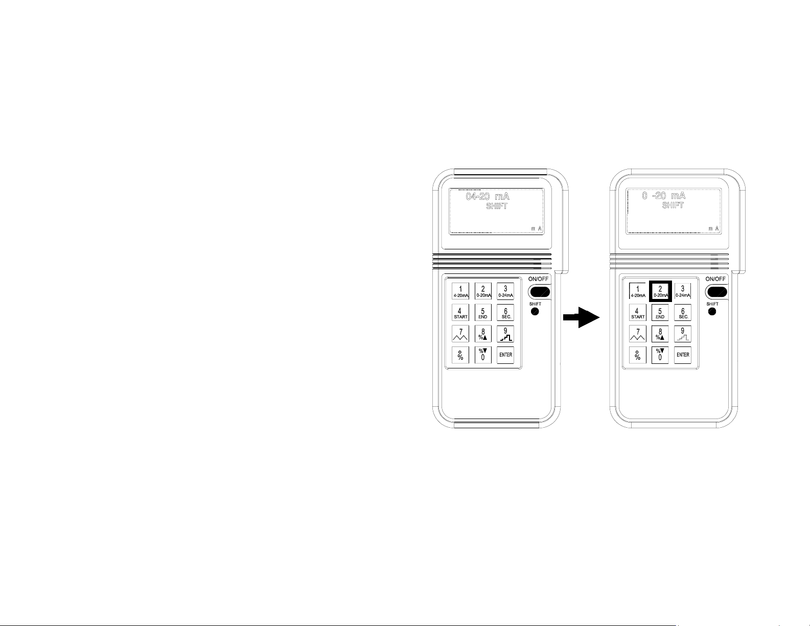
1b. Select 0 - 20mA or 0 - 24mA
The default setting for mA function is 4 - 20mA. But users can select 0 20mA or 0 -24 mA by pressing the SHIFT button to enter the SHIFT mode.
Then press the NUMBER 2 or NUMBER 3 button to select desired DC
current range. After desired range is selected, press the shift button to exit
the SHIFT mode. Corresponding current range symbol will be displayed in
the LCD.
8
Page 13
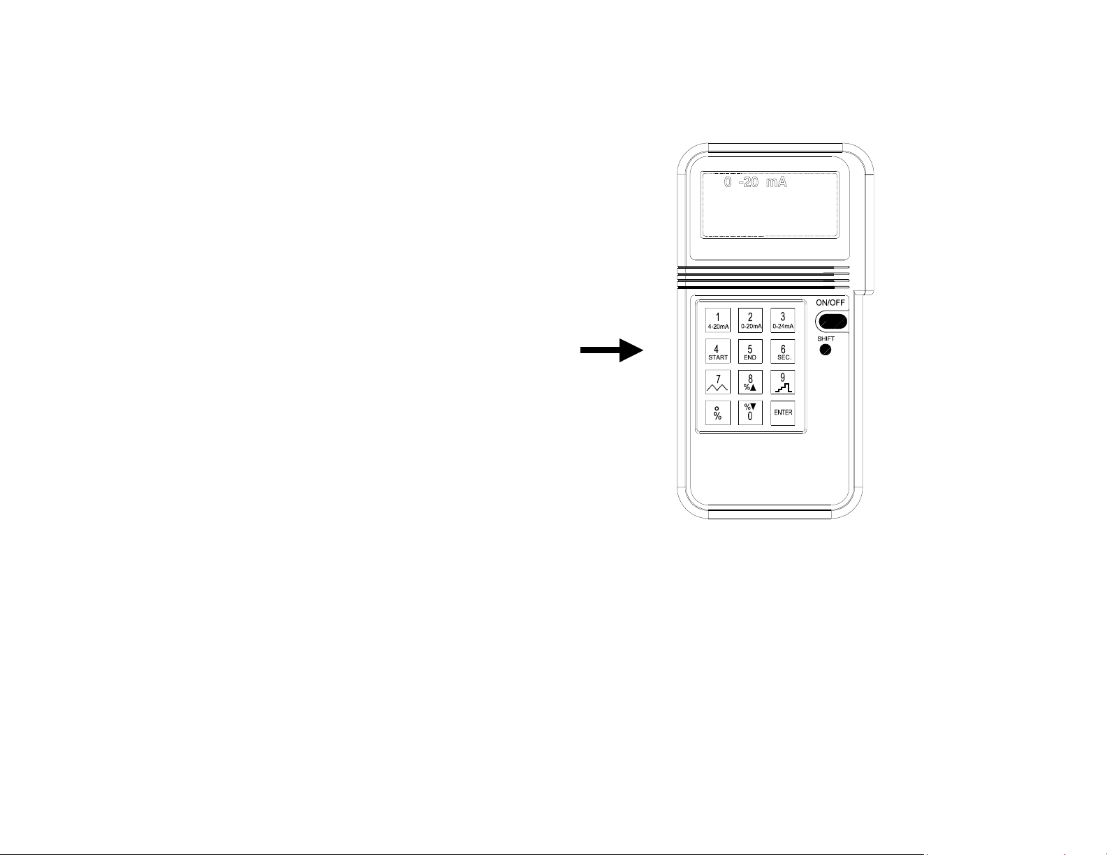
1c. Enter a value less than 1
In the mA functions, the standard way to enter a value less than 1 is to press
leading 0 before pressing the decimal point. Though the decimal point can be
entered, the decimal point will not be shown in the LCD.
2. % (percentage) input
To enter percentage (%)
1. Users press the shift button first, then SHIFT symbol will be
9
Page 14
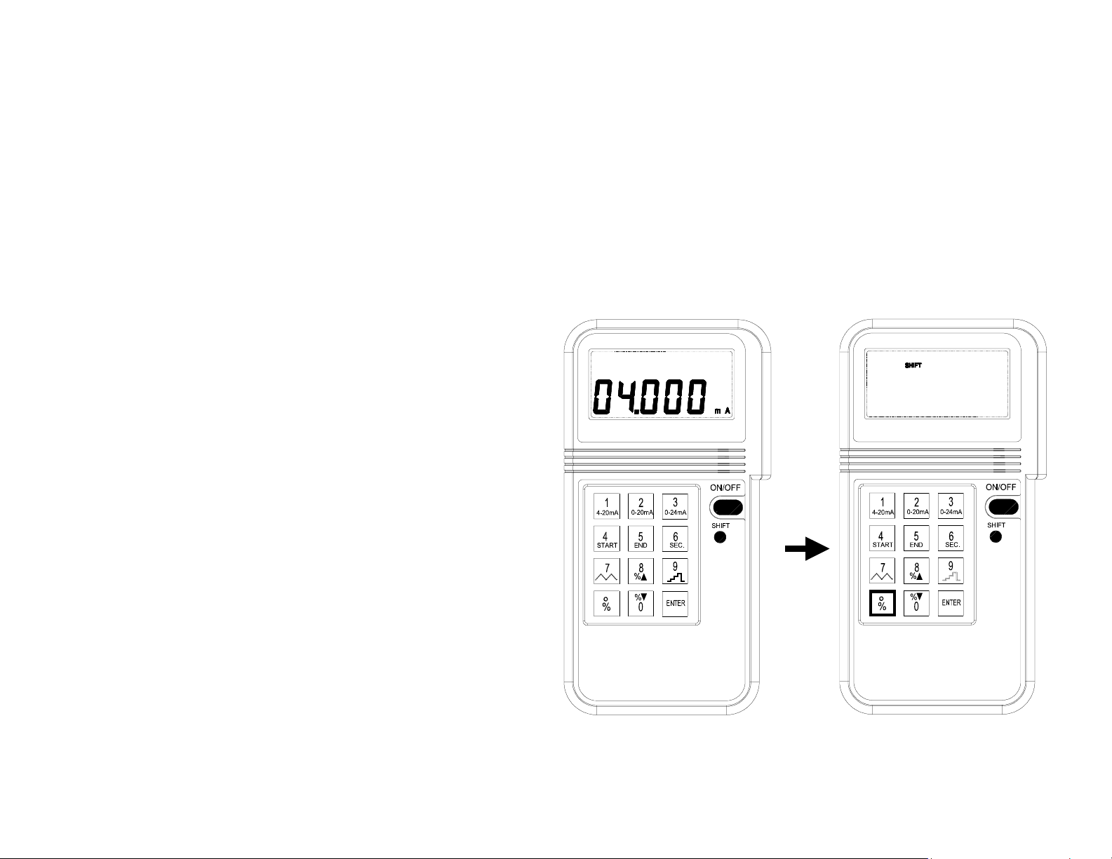
displayed in the LCD.
2 Press % button first, then press the number (no decimal number,
the % resolution is 1%).
3 After percentage is entered, the percentage will be displayed in the
upper LCD, and the corresponding value will be displayed in the
lower LCD.
4. The corresponding value is calculated based upon the range
selected.
4-20mA: 1% = 0.16mA (start at 4 mA)
0-20mA: 1% = 0.2mA
0-24mA: 1% = 0.24mA
5. To exit the percentage-input mode, press the SHIFT button again.
6. After the SHIFT button is pressed, the upper LCD will become
blank, while the lower LCD retains its last value.
10
Page 15
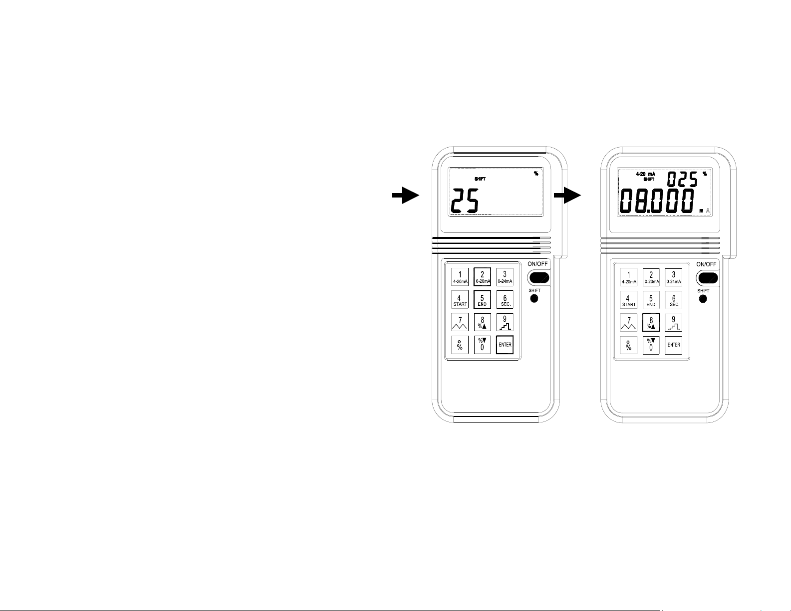
3. Easy Step Up and Down
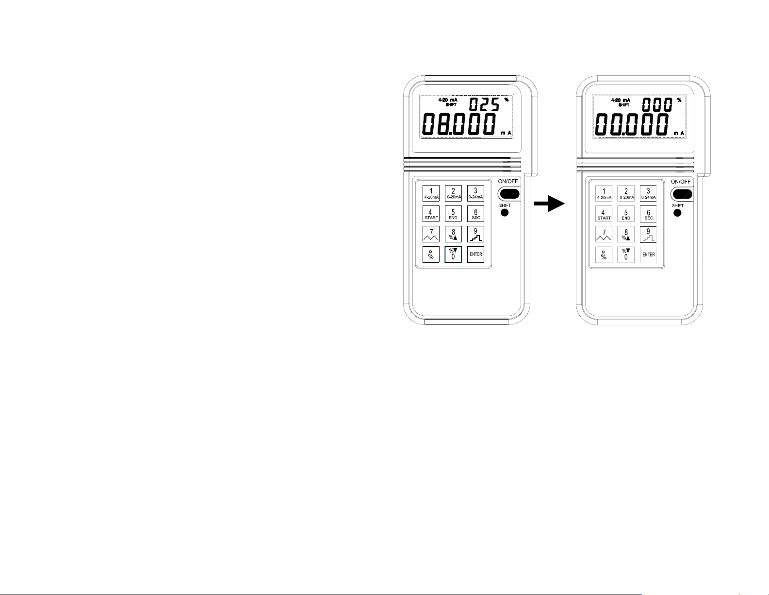
While the percentage is entered and calibrator is still in the SHIFT mode,
users can step up or down by the percentage entered. The maximum
11
Page 16
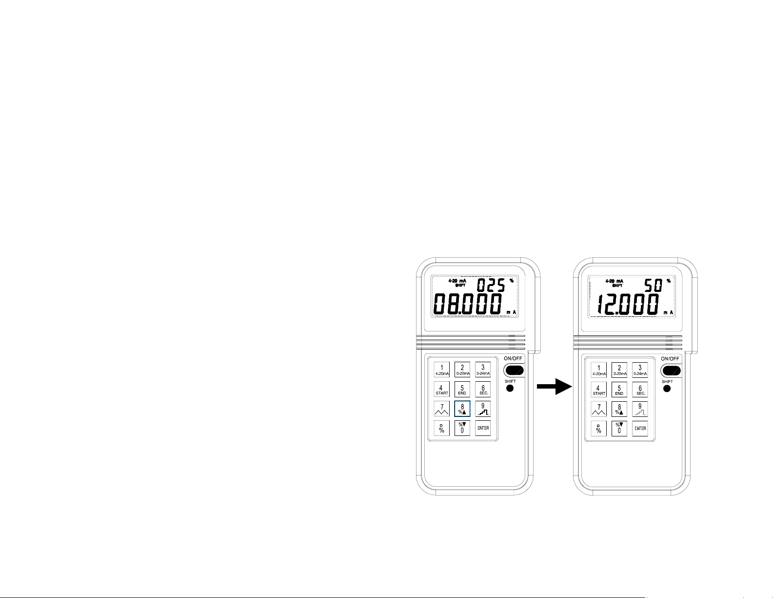
percentage is 100% while the minimum percentage is 0%. If the next step
up or down exceeds the maximum or minimum percentage, the percentage
will stay in the previous step.
Example 1: Step Up and Down(25%):
25% -> 50% -> 75% -> 100% -> 75% -> 50% -> 25% -> 0% -> 25%
Example 2: Step Up and Down(30%):
30% -> 60% -> 90% -> 60% -> 30% -> 0% -> 30%
12
Page 17
4. Auto Step Function:
4a. Start Auto Step Function
The default percentage is 25%, and the default duration for step is 4
13
Page 18

seconds.
1. To start auto step function, press the SHIFT key to enter SHIFT mode.
2. Press the NUMBER 9 key to start. Calibrator outputs 0% of the range
for 4 seconds. Then increment the output to 25% and keep the output
at that value for another 4 seconds, then 75%(4 seconds), 100%(4
seconds), 75%(4 seconds), 25%(4 seconds), 0%(4 seconds), 25%(4
seconds) …
3. To temporarily stop the step function, press the NUMBER 9 key again.
4b. Change the Step Size (%) and Duration
Step Size (%)
1. Press the SHIFT key to enter SHIFT mode.
2. Press the DOT key, enter the value of percentage (%), then press the
ENTER key.
Duration
1. Press the SHIFT key to enter SHIFT mode.
2. Press the NUMBER 6 key, enter the value in seconds for the
DURATION, then press the ENTER key.
14
Page 19
5. Auto Ramp Function
5a. Start Ramp Function
The default setup for the auto ramp function is as followings
RANGE START END DURATION
4-20mA 4mA 20mA 4seconds
0-20mA 0mA 20mA 4secnods
0-24mA 0mA 24mA 4seconds
To start the ramp function:
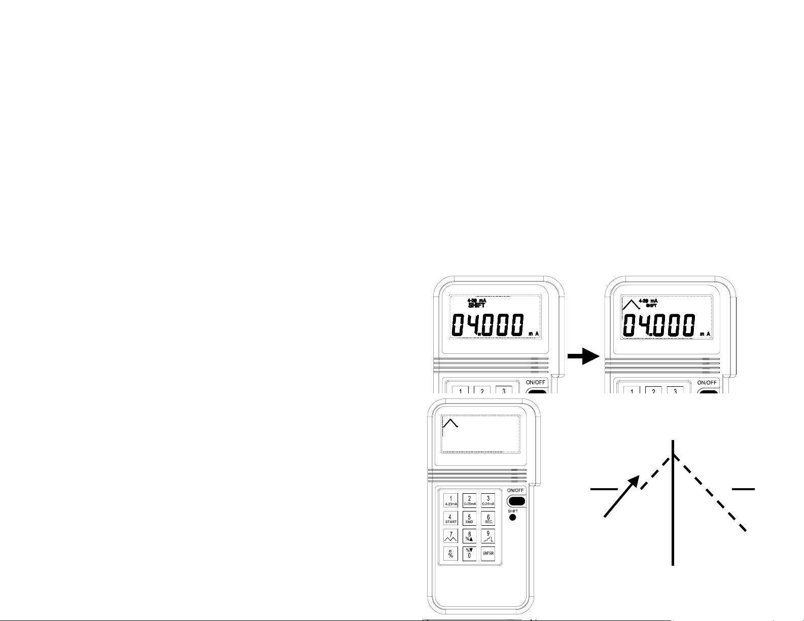
1. Press the SHIFT button to enter the SHIFT mode.
2. Press the NUMBER 7 key to start
3. Calibrator outputs current (mA) from START value to END value in
the DURATION specified by users then outputs from END value to
START value in the DURATION repeatedly.
4. To temporarily stop the ramp function, press the NUMBER 7 key,
and the output will stay at the value when the NUMBER 7 key is
pressed. To restart again, press the NUMBER 7 button again.
5. To return to the regular output mode, press the SHIFT button again
when ramp function is stopped.
15
Page 20
5b. How to change the START, END and DURATION of the RAMP function
START:
1. Press the SHIFT button to enter the SHIFT mode.
2. Press the NUMBER 4 key, then LCD will display STA in the upper
LCD.
3. Enter the desired start value, then press ENTER key.
END:
1. Press the SHIFT button to enter the SHIFT mode.
2. Press the NUMBER 5 key, then LCD will display END in the upper
LCD.
3. Enter the desired end value, then press ENTER key.
DURATION:
1. Press the SHIFT button to enter the SHIFT mode.
2. Press the NUMBER 6 key, then LCD will display SEC in the upper
LCD.
3. Enter the desired duration in seconds, then press ENTER key. The
range for duration is from 1 to 2000 seconds
NOTE: Users should set an appropriate value for the duration of ramp
function. For a full range ramp, users should enter at least 4 seconds for
the duration.
16
Page 21
6. 0 to 24 V Output
To set unit in voltage output mode, hold the “SHIFT” button, then press
the ON/OFF button to turn the power on. When the unit is in Voltage
output mode, the LCD will show symbol of V instead of mA. The mA and
the dash symbols in the range indication will disappear. For example,”0
20” means 0 to 20V. “4 20” means 4 to 20V. “ 0 24” means 0 to 24V. The
default range is 0 to 24V.
The rest of the operation is exactly the same as mA output.
17
Page 22
III. Electrical Specification (23°C ± 5°C)
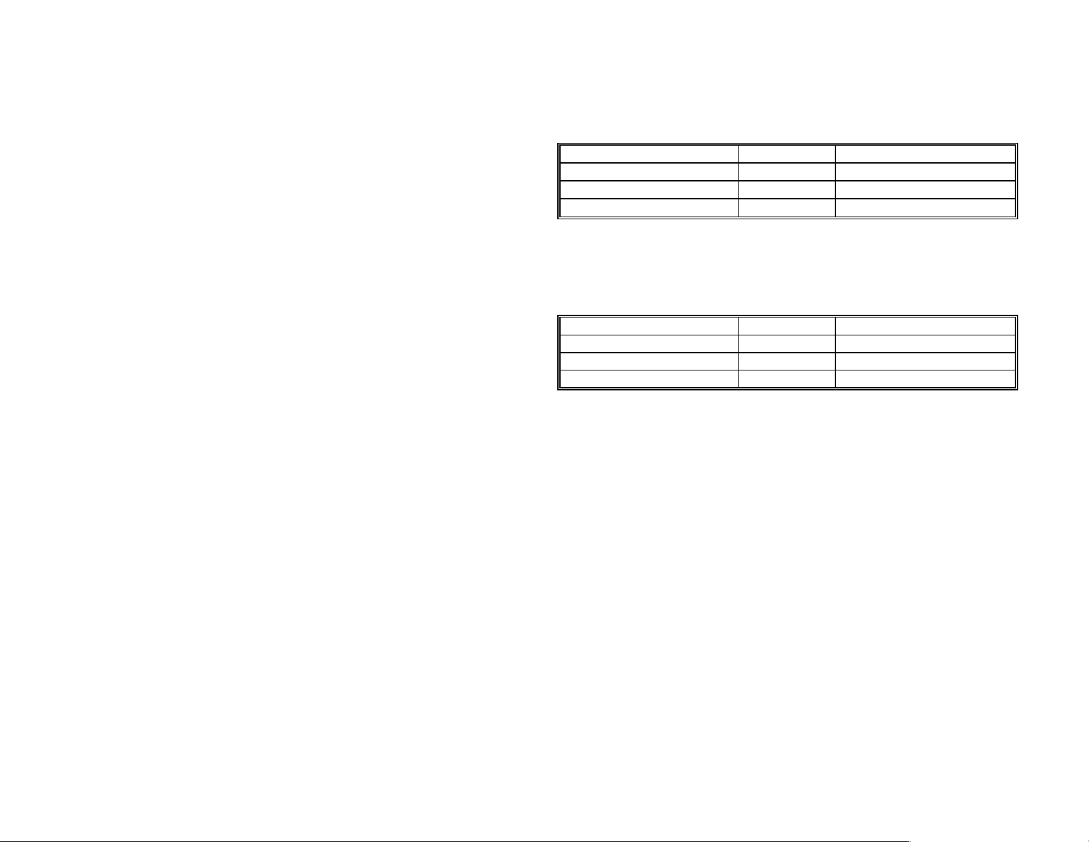
mA DC Current (1K Max. Load, 24V Loop Supply)
Range Resolution Accuracy
0 – 4mA
4 – 20mA
20 – 24mA
Beeper warning when output is open and specified output > 1mA
V DC Voltage
Range Resolution Accuracy
0 – 4V 1mV ± 0.05% ± 10mV
4 – 20V 1mV ± 0.05% ± 5 mV
20 – 24V 1mV ± 0.05% ± 5 mV
Beeper warning when output is short and specified output > 100mV
General Specification:
Battery Type: 9V Alkaline Battery
Power Consumption: 25 mA at 100 load
Display: 4+ 5 Digits
Operating Temperature: 0 to 50°C ( 32 to 122 °F)
Operating Humidity: Less than 85% relative
Storage Temperature: -20 to 60° C (-4 to 140 °F)
Storage Humidity: Less than 85% relative
Dimension: 88 x 168 x 26 mm
Weight: 330 g / 11.63 oz
Accessories: Carrying case x 1
Alligator clip x 1
1µA ± 0.025% ± 10µA
1µA ± 0.025% ± 5µA
1µA ± 0.025% ± 5µA
(3.46" x 6.61" x 1.03")
Users Manual x 1
External Battery Pack
6 1.5V AA Batteries
18
Page 23
IV. Use the AC adapter
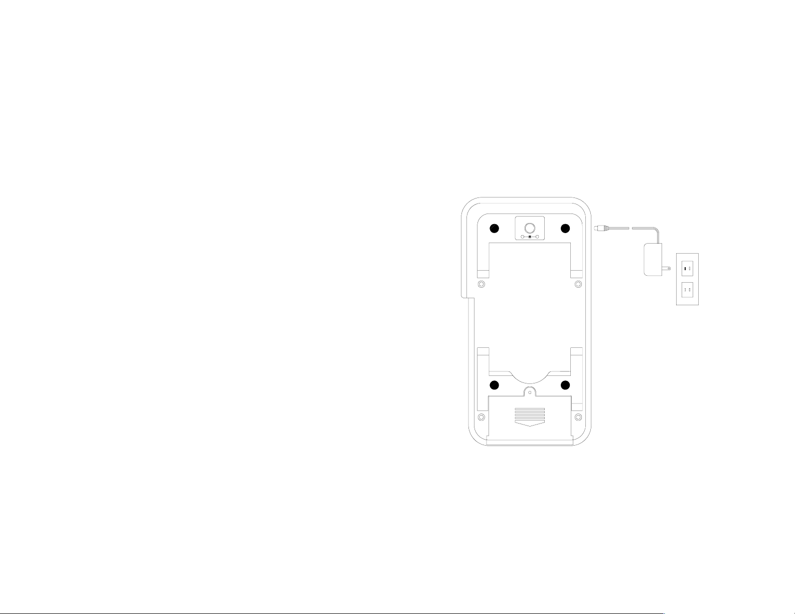
If long term usage of the calibrator is required, AC adapter can be used. The
12V AC terminal is located in the back of the calibrator. The voltage should
be regulated between 9 to 15V.
DC 12V
DC 12V
-
+
V. Use External Battery Pack
An external battery pack is included for a longer period usage. The external
battery pack needs to be packed with 6 pieces of 1.5 volts AA batteries. To
use the external battery pack, plug into the AC terminals located in the back
19
Page 24
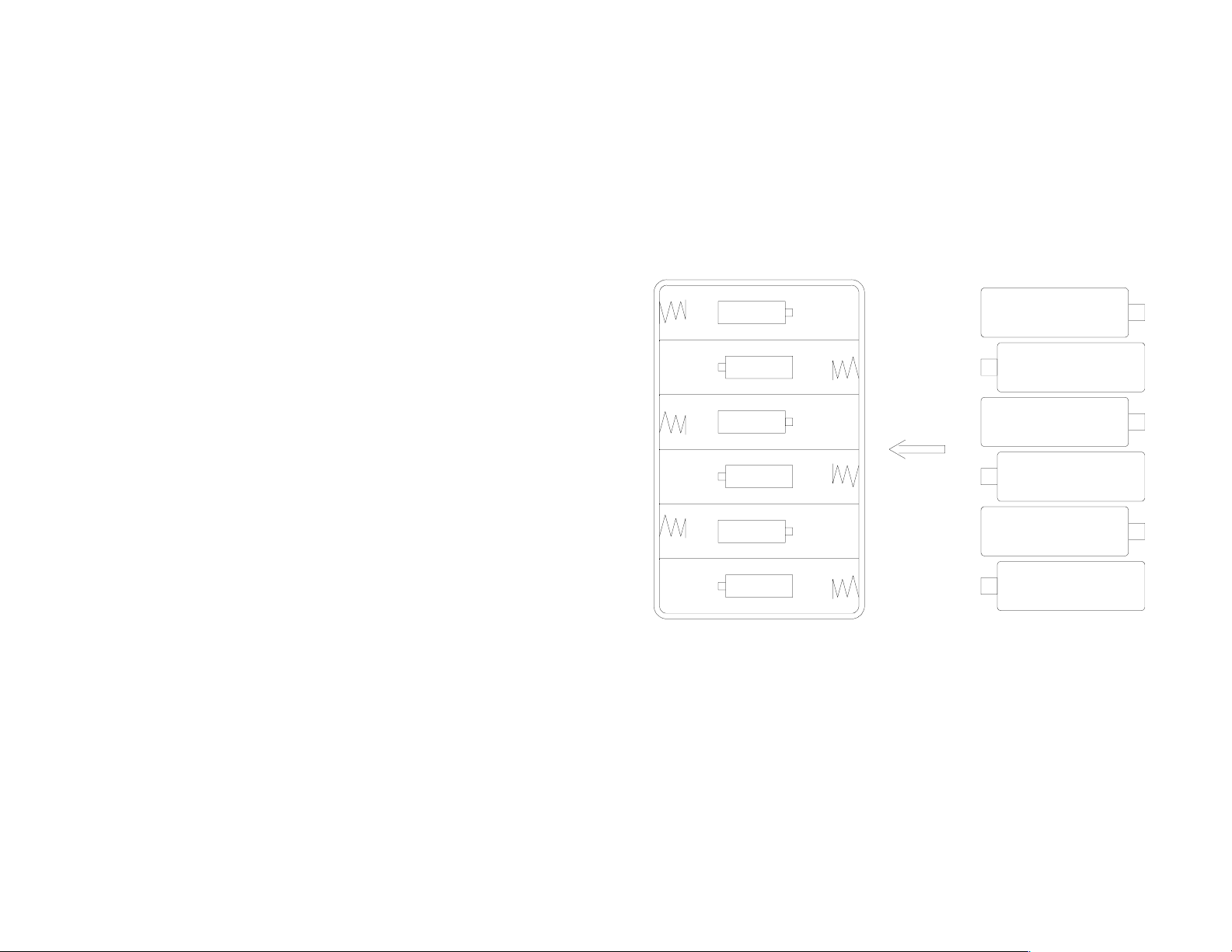
of the calibrator.
BATTERY HOLDER
BATTERIES
6x1.5V AA
-
+
-
+
-
+
+
-
+
-
+
-
20
Page 25
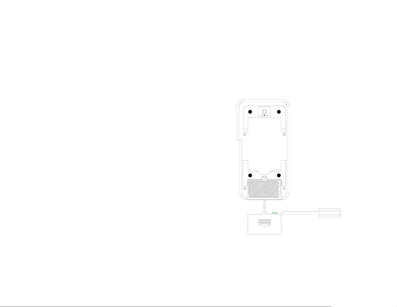
VI. Battery Replacement
When the low battery symbol is displayed on LCD, follow the following
procedures to replace the battery.
1 Turn off the calibrator by pushing the On/Off button.
2 Remove the screw of the battery compartment cover and remove the
battery compartment cover.
3 Replace the old 9V battery with a new alkaline 9V battery.
4 Replace the battery compartment cover and fasten the screw.
-
+
21
Page 26

222324
Page 27
Page 28
 Loading...