

Page 1

Universal Library
TM
for LabVIEW
OMEGA Engineering Inc.
Revision 4
February, 2002
Page 2

NOTICE OF COPYRIGHT AND TRADEMARKS
All rights reserved. No part of this publication may be reproduced, stored in a retrieval system or transmitted,
in any form by any means, electronic, mechanical, by photocopying, recording, or otherwise without the prior
written permission of Measurement Computing Corporation.
MEGA-FIFO, Universal Library, InstaCal, Harsh Environment Warranty, the CIO-, PCM-, and PPIO- part
number prefix and Measurement Computing are registered trademarks of Measurement Computing
Corporation
LabView is a trademark of National Instruments Corp.
DT-Connect is a trademark of Data Translation, Inc.
IBM, PC, and PC/AT are trademarks of International Business Machines Corp.
Information furnished by OMEGA Engineering is believed to be accurate and reliable;
however, no responsibility is assumed by OMEGA Engineering for its use; nor for any
infringements of patents or other rights of third parties which may result from its use. No license is granted by
implication or otherwise under any patent or copyrights of Measurement Computing Corporation.
Each original copy of Universal Library for LabVIEW is licensed for use on one CPU at a time. It is theft to
make copies of this program for simultaneous use. There is nothing but your conscience to protect
OMEGA Engineering’s intellectual property in this product after it is in your possession.
IMPORTANT REVISION NOTES
If any Universal Library functions have changed due to a revision of the software, the heading for that VI will
have the note Changed Rx.x Code. The word ‘Changed’ indicates just that. The Rx.x is the revision number
when the change was made and the code will be MOD, meaning the VI in your program must be modified to
include that option before you can use that VI with that or later revisions of the library, or the code will be ID,
meaning you will only have to modify your code IF Desired to use that VI with the additions and changes.
To simplify management of new features and to prevent the forced rewrite of older code, there is a new VI
that declares the revision number your program was written for. The revision declaration will allow old code
to run with new revisions even if substantial changes have been made to VIs. Please read more about this
under DeclRev.VI.
(C) Copyright 2002
SM UL for LabVIEW.lwp
Page 3

........................
..........
Table of Contents
3 OVERVIEW OF THE UNIVERSAL LIBRARY FOR LABVIEW ..................
4 HOW TO USE THE LABVIEW EXTENSIONS (VIs) ............................
5 UNIVERSAL LIBRARY VIRTUAL INSTRUMENTS (VIs) .......................
ACvtData.VI Changed R3.3 RW (MOD) ................................
ACnvPrDt.VI Changed R3.3 RW (MOD) ..............................
ACalData.VI New R3.3 ...............................................
AIn.VI ..............................................................
AInScBg.VI Changed R3.3 ID .........................................
AInScFg.VI Changed R3.3 ID .........................................
ALoadQue.VI .......................................................
AOut.VI ............................................................
AOutScFg.VI ........................................................
AOutScBg.VI ........................................................
APretrBg.VI .........................................................
APretrFg.VI .........................................................
ATrigger.VI .........................................................
C8254Cfg.VI ........................................................
CBC7266Config() ....................................................
C8536Cfg.VI ........................................................
C8536Init.VI ........................................................
C9513Config.VI ......................................................
CFreqIn.VI ..........................................................
CIn.VI ..............................................................
cbCIn32() ...........................................................
CLoad.VI ...........................................................
cbCLoad32() ........................................................
cbCStatus() ..........................................................
Returns - Error code or 0 if no error occurs .............................
CStore.VI Changed R4.0 RW (MOD)
11 INTRODUCTION ............................................................
12 INSTALLATION AND CONFIGURATION .....................................
12.1 INSTALLATION .........................................................
12.2 CB.CFG FILE ...........................................................
2
23.1 ANALOG I/O VIs ........................................................
33.2 DIGITAL I/O VIs ........................................................
43.3 THERMOCOUPLE INPUT VIs .............................................
43.4 COUNTER VIs ..........................................................
53.5 STREAMER FILE VIs ....................................................
53.6 MISC. VIs ..............................................................
63.7 MEMORY BOARD VIs ...................................................
7
74.1 USING THE LIBRARY WITH LabVIEW ....................................
74.2 CONTEXTS .............................................................
84.3 EXAMPLES VI’S ........................................................
9
9
10
11
12
13
15
17
18
18
21
23
25
27
285.1 COUNTERS - AN INTRODUCTION .......................................
285.2 COUNTER CHIP VARIABLES ...........................................
29
30
32
33
34
38
40
41
42
43
44
44
45
iii
Page 4

...............................
..........
Table of Contents
OutByte.VI / OutWord.VI .............................................
DCfgPort.VI .........................................................
DInScBg.VI .........................................................
DInScFg.VI .........................................................
DOut.VI ............................................................
DOutScBg.VI ........................................................
DOutScFg.VI ........................................................
ErrHdlng.VI .........................................................
ErrMsg.VI ..........................................................
FileAInS.VI .........................................................
FileInfo.VI ..........................................................
FilePret.VI ..........................................................
FileRead.VI .........................................................
FromEng.VI .........................................................
ToEng.VI ...........................................................
GetBoard.VI ........................................................
GetCfg.VI ...........................................................
GetStatus.VI ........................................................
MemRdPrt.VI .......................................................
MemRead.VI ........................................................
MemReset.VI ........................................................
MemSetDT.VI .......................................................
MemWrite.VI .......................................................
OptAIn.VI Changed R3.3ID ..........................................
SelChan.VI ..........................................................
ScaleArr.VI .........................................................
ScalePnt.VI ..........................................................
SetCfg.VI ...........................................................
cbSet Trigger() .......................................................
StopBg.VI ...........................................................
TIn.VI Changed R3.3 ID .............................................
TInScan.VI Changed R3.3 ID
46DBitIn.VI ...........................................................
47DBitOut.VI ..........................................................
48InByte.VI/ InWord.VI ................................................
49
50
52
54
55
56
58
59
60
61
63
64
66
67
67
69
70
73
75
76
77
78
79
80
82
83
84
85
87
89
90
92
iv
Page 5

1 INTRODUCTION
The Universal Library for LabVIEW, includes the LabVIEW virtual instruments (VIs) that you need to construct your own programs
in LabVIEW using OMEGA’s data acquisition and control boards. This is the manual for Universal Library for LabVIEW only. Although the LabVIEW extensions follow very closely the syntax of the Universal Library, there are some differences.
For LabVIEW syntax, please use this manual. If you decide to use the Universal Library with another language, please use the Universal Library programming manual, not this one.
2 INSTALLATION AND CONFIGURATION
This chapter describes how to install the software on your computer and how to configure the software for the boards that you will be
using with it.
2.1 INSTALLATION
The Universal Library for LabVIEW is contained on a CD. The CD contains the software for installation under all Universal Library
supported operating systems. To install the package simply insert the CD and run the setup application. The setup application will
ask for target installation directories. This release contains the LabVIEW extension VI’s and examples as well as the Universal
Library and InstaCal.
Please refer to the Software Installation Manual for detailed Universal Library installation information.
Note that not all sections are required for installation on every platform.
Please refer to the readme.txt file for any further installation details.
2.2 CB.CFG FILE
The LabVIEW VIs are dependent on the CB.CFG file in the same way as the Universal Library functions are. Please refer to the
Installation and Configuration section of the Universal Library User's Manual for an explanation of the CFG file and its interaction
with the Universal Library for LabVIEW.
1
Page 6

3 OVERVIEW OF THE UNIVERSAL LIBRARY FOR LABVIEW
The Universal Library for LabVIEW consists of a set of low-level VIs that you “wire” together to form your application. These VIs
are grouped according to their purpose. All of the groups except for Misc. are based on the type of devices they are used with.
3.1 ANALOG I/O VIs
The Analog VI names all begin with "A". These VIs perform analog input and output and convert analog data.
AIn.VI - Single Analog input
Takes a single reading from an analog input channel (A/D).
AInScBg.VI - Background Analog Input Scan
Repeatedly scans a range of analog input (A/D) channels in the background. The channel range, the number of iterations, the sampling rate, and the A/D range can all be specified. The data that is collected is stored in an array.
AInScFg.VI - Foreground Analog Input Scan
Repeatedly scans a range of analog input (A/D) channels in the foreground. The channel range, the number of iterations, the sampling rate, and the A/D range can all be specified. The data that is collected is stored in an array.
ALoadQue.VI - Load Chan/Gain queue
Loads a series of chan/gain pairs into A/D board's queue. These chan/gains will be used with all subsequent analog input VIs.
AOut.VI - Single analog output
Outputs a single value to an analog output (D/A).
AOutScBg.VI - Background Analog output scan
Repeatedly scans a range of analog output (D/A) channels in the background. The channel range, the number of iterations, and the
rate can all be specified. The data values from consecutive elements of an array are sent to each D/A channel in the scan.
AOutScFg.VI - Foreground Analog output scan
Repeatedly scans a range of analog output (D/A) channels in the foreground. The channel range, the number of iterations, and the
rate can all be specified. The data values from consecutive elements of an array are sent to each D/A channel in the scan.
APretrBg.VI - Analog pre-triggered input in the Background
Repeatedly scans a range of analog input (A/D) channels in and after background while waiting for a trigger signal. When a trigger
occurs it returns the specified number of samples and points before the trigger occurred. The channel range, the sampling rate, and
the A/D range can all be specified. All of the data that is collected is stored in an array.
APretrFg.VI - Analog pre-triggered input in the foreground
Repeatedly scans a range of analog input (A/D) channels in and after foreground while waiting for a trigger signal. When a trigger
occurs it returns the specified number of samples and points before the trigger occurred. The channel range, the sampling rate, and
the A/D range can all be specified. All of the data that is collected is stored in an array.
ATrig.VI - Analog trigger
Reads the analog input and waits until it goes above or below a specified threshold. When the trigger condition is met the current
sample is returned.
ACvtData.VI - Converts analog data
Each raw sample from analog input is a 16-bit value. On some 12-bit A/D boards it consists of a 12-bit A/D value along with a four
bit channel number. On 16-bit A/D boards it contains the 16-bit A/D value.
2
Page 7

This conversion is done automatically by the AIn VI. It can also be done automatically by the AInScxx VI with the CONVERTDATA option. In some cases though, it may be useful or necessary to collect the data and then do the conversion sometime later. The
ACvtData.VI takes a buffer full of unconverted data and converts it.
ACnvPrDt.VI - Convert pre-trigger data
When data is collected with the APretrxx.VI, the same conversion needs to be done as described above for ACvtData. There is a further complication though.
APretrxx.VI collects analog data into an array. It treats the array like a circular buffer. While it is waiting for the trigger to occur it
fills the array. When it gets to the end it resets to the start and begins again. When the trigger signal occurs it continues collecting
data into the circular buffer until the requested number of samples have been collected.
When the data acquisition is complete all of the data is in the array but it is in the wrong order. The first element of the array does
not contain the first data point. The data has to be rotated in the correct order.
This conversion can be done automatically by the APretrxx VI with the CONVERTDATA option. In some cases though, it may be
useful or necessary to collect the data and then do the conversion sometime later. The ACnvPrDt.VI takes a buffer full of unconverted data and converts it.
ACalData.VI - Calibrates raw data
Calibrates raw data collected by cbAInScan() when the real time software calibration has been turned off.
3.2 DIGITAL I/O VIs
The digital VI names all begin with "D". These VIs perform digital input and output. They operate on all types of digital I/O ports.
DBitIn.VI - Digital bit input
Reads a single bit from a digital input port.
DBitOut.VI - Digital bit output
Sets a single bit on a digital output port.
DCfgPort.VI - Configures digital outputs
Selects whether a digital port is an input or an output.
DIn.VI - Digital byte input
Reads a specified digital input port.
DInScBg - Digital multiple byte input in the background.
Reads a specified number of bytes from a digital input port at a specified rate.
DInScFg - Digital multiple byte input in the foreground.
Reads a specified number of bytes from a digital input port at a specified rate.
DOut.VI - Digital byte output
Writes a byte to a digital output port.
DOutScBg.VI - Digital multiple byte output in the background.
Writes a series of bytes to a digital output port at a specified rate.
DOutScFg.VI - Digital multiple byte output in the foreground.
Writes a series of bytes to a digital output port at a specified rate.
3
Page 8

3.3 THERMOCOUPLE INPUT VIs
The thermocouple VI names begin with "T". These VIs convert a raw analog input from a temperature measurement board to
temperature.
TIn.VI - Single thermocouple input
Reads temperature and, as necessary, filters it, does the cold junction compensation, linearization and converts it to temperature.
TInScan.VI - Scan a range of thermocouple inputs
Reads the temperature from a range of channels as described above. Returns the temperature values to an array.
3.4 COUNTER VIs
The counter VI names begin with "C". These VIs load, read and configure counters. There are four types of counter chips used in
Computer Board products: 8254, 8536, 7266, and 9513. Some of the counter commands only apply to one type of counter.
C8254Cfg.VI - Configures 8254 counter
Selects the basic operating mode of an 8254 counter.
C8536Cfg.VI - Sets operating mode of 8536 counter.
This VI sets all of the programmable options that are associated with an 8536 counter chip.
C8536Ini.VI - Initializes 8536 counter
Initializes and selects all of the chip level features for a 8536 counter board. The options that are set by this command are associated
with each counter chip, not the individual counters within it.
C9513Cfg.VI - Sets operating mode of 9513 counter.
This VI sets all of the programmable options that are associated with a 9513 counter chip. It is similar in purpose to C8254Cfg.VI
except that it is used with a 9513 counter.
C9513Ini.VI - Initializes 9513 counter
Initializes and selects all of the chip level features for a 9513 counter board. The options that are set by this command are associated
with the each counter chip, not the individual counters within it.
CFreqIn.VI - Measures frequency of a signal
This VI measures the frequency of a signal by counting it for a specified period of time (GatingInterval) and then converting the
count to count/sec (Hz). It only works with 9513 counters.
CIn.VI - Reads a counter.
Reads a counters current values.
CLoad.VI - Load a counter.
Loads a counter with an initial count value.
CStore.VI - Store counter value when interrupt occurs.
Installs an interrupt handler that will store the current count whenever an interrupt occurs. This VI only works with 9513 counters.
4
Page 9

3.5 STREAMER FILE VIs
The file VI names begin with "F". These VIs create, fill, and read "streamer" files. These VIs also let you collect large amounts of
analog input data. The amount of data is limited only by available disk space.
FileAInS.VI - Transfer analog input data directly to file.
Very similar to AInScxx.VI except that the data is stored in a file instead of an array.
FilePret.VI - Pre-triggered analog input to a file.
Very similar to APretrxx.VI except that the data is stored in a file instead of an array.
FileInfo.VI - Reads "streamer" file information.
Each streamer file contains information about how much data is in the file and the conditions under which it was collected (sampling rate, channels, etc.). This VI reads that information.
FileRead.VI - Reads data from "streamer" file.
Reads a selected number of data points from a streamer file into an array.
3.6 MISC. VIs
These VIs perform error handling and managing background operations.
ErrHdlng.VI - Selects type of error handling.
The universal library has a number of different methods of handling errors. This VI selects which of these methods will be used with
all subsequent library calls. The options include stopping the program when an error occurs and printing error messages.
ErrMsg.VI - Returns an error message for a given error.
All library VIs return error codes. This VI converts an error code to an error message.
GetBoard.VI - Get board name.
Returns the name of the selected target board.
GetCfg.VI - Get configuration options.
Extracts hardware configuration options from board configuration file.
GetStat.VI - Returns status of background operation.
After a background operation is started your program will need to periodically check on its progress. This VI returns the current
status of the process.
FromEng.VI - Convert to raw data.
Converts one data sample from engineering units to raw data format.
InByte.VI - Read one byte.
Reads one byte of data from the specified port.
InWord.VI - Read one word.
Reads one word of data from the specified port.
StopBg.VI - Stop a background process.
It is sometimes necessary to stop a background process in the case of an error or if the process has been set up to run continuously
forever. This VI will stop a background process that is running.
OptAIn.VI - Analog In Option Generator
The AInScxx.VIs have an input called options which should be wired to this VIs output. It generates a value based on the ANDED
values of its inputs.
5
Page 10

OutByte.VI - Write one byte.
Writes one word of data to the specified port.
OutWord.VI - Write one word.
Writes one word of data to the specified port.
ScaleArr.VI - Converts raw data in an array to engineering data in an array.
SetCfg.VI - Set configuration options.
Sets hardware configuration options for selected board.
ScalePnt.VI - Converts a raw data point to engineering units.
SelChan.VI - Select data from array.
Allows one channel of data to be extracted from an array of interleaved data for multiple channels.
SetTrig.VI - Set the trigger source.
Configures the type and threshold of external trigger signals.
ToEng.VI - Convert to engineering units.
Converts one data sample from raw data format to engineering units.
3.7 MEMORY BOARD VIs
The memory board VIs all begin with "M". These VIs read/write and control memory boards (MEGA-FIFO).
The most common use for the memory boards is to store large amounts of data from an A/D board via a DT-Connect cable between
the two boards. To do this, you should use the EXTMEMORY option with AInScxx.VI or APretrxx.VI.
After the data has been transferred to the memory board you can use the memory VIs to retrieve the data.
MemSetDT.VI - Set DT-Connect Mode on Memory Board
The memory boards have a DT-Connect interface which can be used to transfer data through a cable between two boards rather than
through the PC's system memory. The DT-Connect port on the memory board can be configured as either an input (from an A/D) or
as an output (to a D/A). This VI configures the port.
MemReset.VI - Resets the Memory Board Address
The memory board is organized as a sequential device. When data is transferred to the memory board it is automatically put in the
next address location. This VI resets the current address to the location 0.
MemRead.VI - Read Data From Memory Board
Reads a specified number of points from a memory board starting at a specified address.
MemWrite.VI - Writes Data To The Memory Board
Writes a specified number of points to a memory board starting at a specified address.
MemRdPrt.VI - Reads Data Collected With APretrxx.VI
The APretrxx.VI writes the pre-triggered data to the memory board in a scrambled order. This VI unscrambles the data and returns
it in the correct order.
6
Page 11

4 HOW TO USE THE LABVIEW EXTENSIONS (VIs)
4.1 USING THE LIBRARY WITH LabVIEW
The Universal Library LabVIEW extensions provide a complete set of Virtual Instruments (VIs) for interfacing OMEGA's
data acquisition hardware. Each low-level VI corresponds to one Universal Library function. All of the VI’s are com bined into a LabVIEW Library named DAS16.LLB. There are two approaches to developing new LabVIEW applications that can
interface to data acquisition hardware. The first approach is to modify one of the example applications. The second
approach is to build a new application from scratch using the low-level VI’s supplied in the DAS16.LLB library.
The easiest way to get started is to modify one of the sample applications. Select an example application that contains the desired
operating behavior. The example applications contain the basic requirements for transferring data to and from the target hardware.
Additional capability can be added by selecting new functions and placing them on the diagram window. The corresponding controls
can then be selected and placed on the panel window. Wire the new functions to the existing application and test.
The second development method is to build up an application from scratch. Starting from scratch any LabVIEW functions can be
wired together to build your application. When the application requires interaction with the data acquisition hardware simply select
the appropriate VI from the DAS16.LLB and add it to the working diagram.
The easiest way to access the DAS16.LLB library VI’s is to copy the DAS16.LLB file into the \User.lib subdirectory of the LabVIEW
package. By default the DAS16.LLB file will be copied to the example directory during installation. After this task is completed the
individual VI’s will be visible under the “User Libraries” icon on the Function palette. To bring up the Function palette do the following:
• Make the “Diagram” window of the project the active window. If the “Panel” view is currently active then select the ‘Windows” title bar option followed by “Show Diagram”.
• From the “Diagram” window select the “Windows” title bar option followed by “Show Functions Palette”.
• The “Functions Palette” will appear as a separate window with icons. The bottom left hand corner icon should be labeled
“User Libraries” when the cursor is placed over the icon. Select this icon and move the cursor to the sub-icon. After the cursor is placed over the sub-icon the complete set of DAS16.LLB VI’s will be displayed in the window.
• Select the desired VI by single clicking on the appropriate icon. Move the cursor back to the working “Diagram” and click
on the position to drop the VI.
After all of the objects have been placed on the diagram they can then be wired together. Finally save out the application prior to
testing. Refer to the documentation for the individual VI’s for specifics on the input and output parameters.
4.2 CONTEXTS
There are two distinct VIs for every UL function featuring background operation. One is for foreground operation only and the other
is for background operation only. The last two letters of their names are "Fg" and "Bg" for foreground and background respectively.
Their parameter lists differ in that background VIs have a Context output that must be wired to subsequent VIs (GetStat.Vi and
StopBg.VI). Context is an output data structure that contains information such as the board number, the data array, the size of the
data array, the initial status of the operation, and the error code. Connecting a Probe to the Context wire will display the elements in
the data structure and allow you to check their intermediate values if desired. In general, the background VIs should conform to the
wiring pattern shown in Figure 4-1. There are several example programs that effectively demonstrate the correct wiring and use of
Contexts. Please refer to those VIs for more details.
7
Page 12
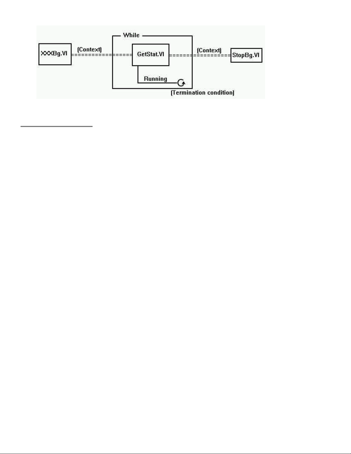
Figure 4-1. Background VIs General Wiring Pattern
4.3 EXAMPLES VI’S
There are many example programs included with this package that demonstrate how to use the low level VIs. We strongly suggest
that you review these examples before you begin. They will help you understand how to integrate the extensions into your program.
The following list of example programs has a brief description of ea ch function:
Example VI Description
XAIN Single analog input in a while loop with a metered display.
XAINSCBG Analog input scan in the background. Uses GetStat, StopBg and OptAin VIs. Display's data on a graph.
XAICNBG Analog input scan in the background in the CONTINUOUS mode. Same as XAINSCBG but runs
continuously displaying data in real time.
XAINSCFG Analog input scan in the foreground. Uses SelChan and OptAIn VIS. Display's data on a graph.
XAOUT Single analog output. Demonstrates sequences, case statements, for loops and while loops.
XAOUTSCB Analog output scan in the background. Uses GetStat and StopBg VIs.
XAOUTSCF Analog output scan in the foreground. Generates sinusoidal data.
XAPRETRB Analog pre-trigger in the background. Uses GetStat, StopBg and ACnvPrDt VIs. Displays a graph.
XAPRETRF Analog pre-trigger in the foreground. Uses SelChan and ACnvPrDt VIS. Displays a graph.
XASCFILE Analog input to a file. Uses FileAInS and FileRead. Display's data on a graph.
XASCMEM Analog input to memory board. Uses MemReset and MemRead. Display's data on a graph.
XCFREQ Displays frequency of signal at counter input. Uses C9513Ini and CFreqIn.
XCSTORE Stores counter values when interrupts occur and displays them. Uses CStore, GatStat, and StopBg.
XCTR8254 Configures, loads and reads the counter. Displays the count. Uses C8254Cfg, CLoad, and CIn.
XCTR8536 Initializes, configures, loads, and reads the counter. Displays the count. Uses C8536Cfg, C8536Cfg,
Cload, and CIn.
XCTR9513 Initializes, configures, loads, and reads the counter. Displays the count. Uses C9513Cfg, C9513Cfg,
Cload, and CIn.
XCTR7266 Configures, loads, and reads the counter. Displays count and status. Uses C7266Cfg, CLoad32, CIn32,
and Cstatus.
XDBITIN Configures and reads a digital bit. Toggles an LED accordingly. Uses DCfgPort and DBitIn.
XDBITOUT Configures and writes a digital bit. Uses DCfgPort and DBitOut.
XDIN Configures and reads a digital port. Toggles 8 LED's accordingly. Uses DCfgPort and DIn.
XDINSCBG Reads multiple bytes in the background. Uses DCfgPort, DInScBg, GetStat and StopBg.
XDINSCFG Reads multiple bytes in the foreground. Uses DCfgPort, DInScFg.
XDOUT Configures and writes a digital port. Uses DCfgPort and DOut.
XDOUTSCB Writes multiple bytes in the background. Uses DCfgPort, DOutScBg, GetStat and StopBg.
XDOUTSCF Writes multiple bytes in the foreground. Uses DCfgPort, DOutScFg
8
Page 13
5 UNIVERSAL LIBRARY VIRTUAL INSTRUMENTS (VIs)
ACvtData.VI Changed R3.3 RW (MOD)
Description:
Converts the raw data collected by AInScFg.VI or AInScBg.VI into 12-bit A/D values. The AInScxx VIS can return either raw A/D
data or converted data depending on whether or not the CONVERTDATA option was set. For many 12-bit A/D boards, the raw data
is a 16-bit value that contains a 12-bit A/D value and a 4 bit channel tag (see board-specific information or hardware manual). The
converted data consists of just the 12-bit A/D value.
Summary:
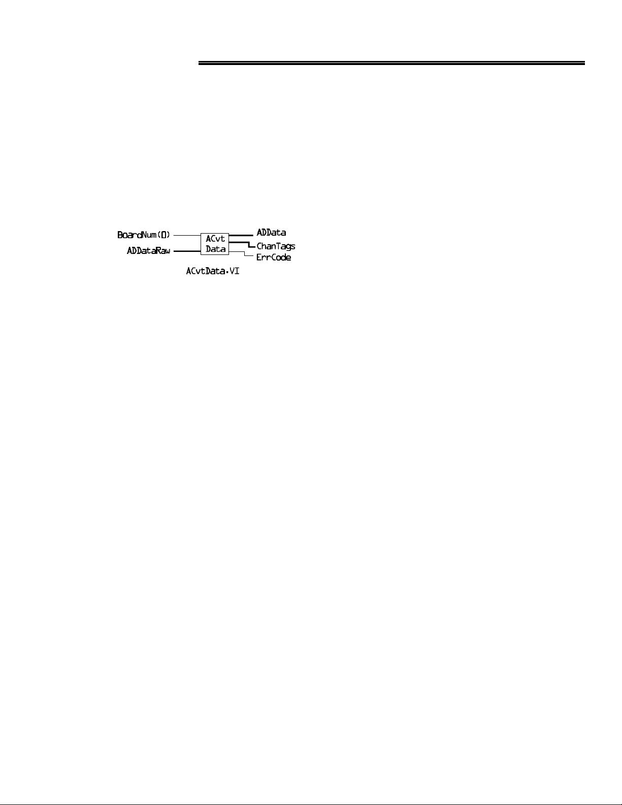
Inputs: BoardNum [U32] - The board number when installed with InstaCal. Can be 0 to 100.
ADDataRaw [U16]- Data and channel tags from AInScxx.VI.
Outputs: ADData [U16]- converted data
ChanTags [U16] - channel tags if available
ErrCode [I32]- Error code
Explanation of the Arguments:
When you collect data with AInScxx and you don't use the CONVERTDATA option, you may need to use this VI to convert the data
after it is collected. There are cases where the CONVERTDATA option is not allowed. For example, if you are using the DMAIO
option with AInScBg. In this case, use this VI to convert the data after the data collection is complete.
On some boards, each raw data point consists of a 12-bit A/D value with a 4-bit channel number. This VI pulls each data point apart
and puts the A/D value into the ADData array and the channel number into the ChanTags array.
Note - 12-Bit A/D Boards
1) Upon returning from ACvtData , ADData array contains only 12-bit A/D data.
Note - 16-Bit A/D Boards
This VI is not for use with 16-bit A/D boards. If this function is called for a 16-bit board, it is simply ignored. No error is returned.
9
Page 14
ACnvPrDt.VI Changed R3.3 RW (MOD)
Description:
Converts the raw data collected by APretrFg.VI or APretrBg.VI. The APretrxx VI can return either raw A/D data or converted data
depending on whether or not the CONVERTDATA option was used. The raw data as it is collected is not in the correct order. After
the data collection is completed it must be rearranged into the correct order. This VI correctly orders the data, starting with the first
pretrigger data point and ending with the last post-trigger point.
Change at revision 3.3 is to support multiple background
Summary:
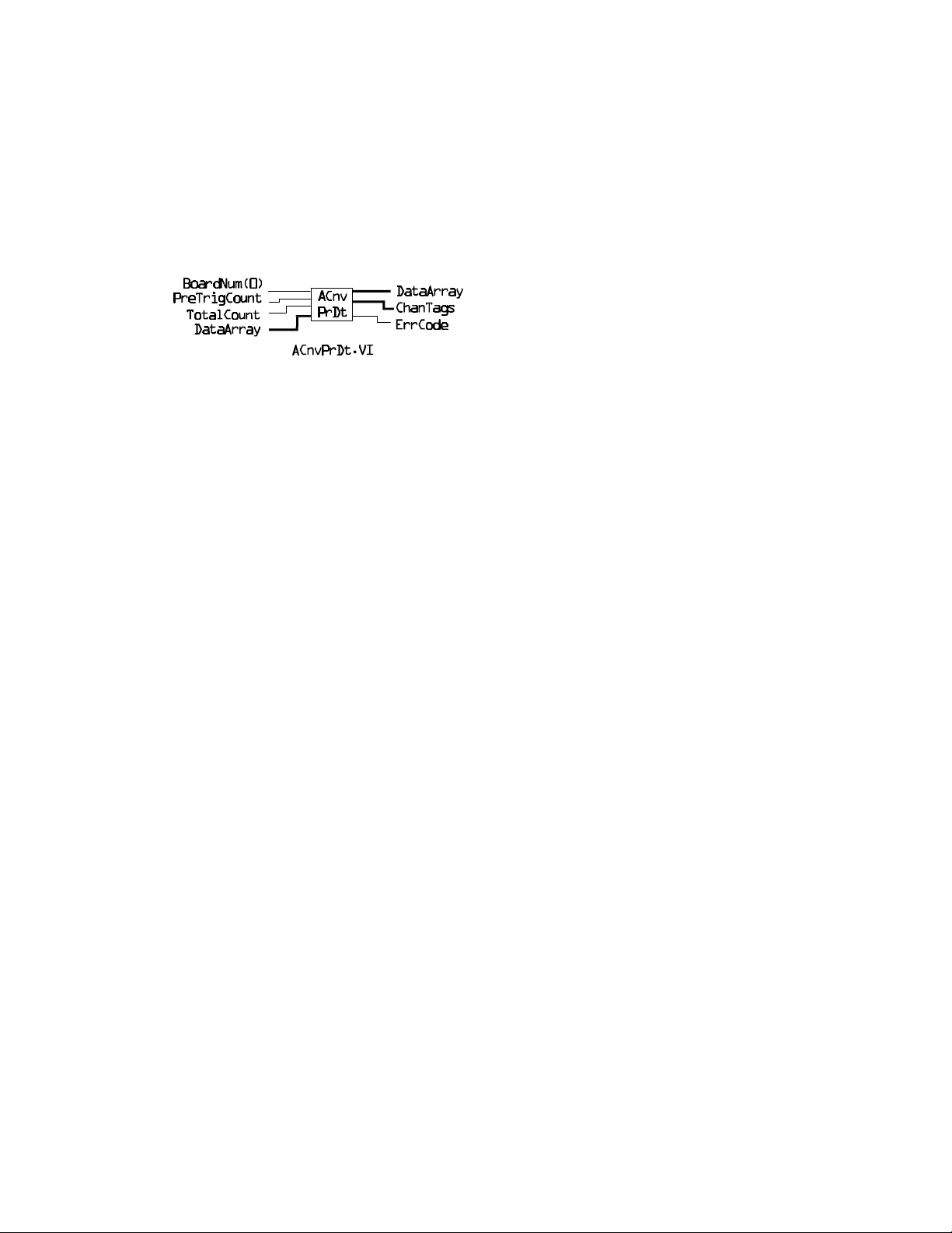
Inputs: BoardNum [U32] - The board number when installed with InstaCal. Can be 0 to 100.
PreTrigCount [I32] - Number of pre-trigger samples
Total Count [I32] - Total number of samples that were collected
DataArray [U32] - Data and channel tags
Outputs: DataArray [U32]- Converted data
ChanTags [I16]- channel tags if available
ErrCode [I32]- Error code
Explanation of Arguments:
When you collect data with APretrFg VI or APretrBg VI and you don't use the CONVERTDATA option then you must use this VI
to convert the data after it is collected. There are cases where the CONVERTDATA option is not allowed. For example - if you use
the BACKGROUND option with APretrxx.VI. In those cases this VI should be used to convert the data after the data collection is
complete.
Note - 12-bit A/D Boards
On some 12-bit boards, each raw data point consists of a 12-bit A/D value with a 4-bit channel number. This VI pulls each data
point apart and puts the A/D value into the DataArray and the channel number into the ChanTags array.
Upon returning from APretrxx.VI, DataArray contains only 12-bit A/D data.
Note - 16-bit A/D Boards
This VI is for use with 16-bit A/D boards only insofar as ordering the data. No channel tags are returned.
10
Page 15
ACalData.VI New R3.3
Description:
Calibrates the raw data collected by AInScxx from boards with real-time software calibration capability but the real-time calibration
has been turned off. The AInScxx VI can return either raw A/D data or calibrated data depending on whether or not the NOCALIBRATEDATA option was used.
Summary:
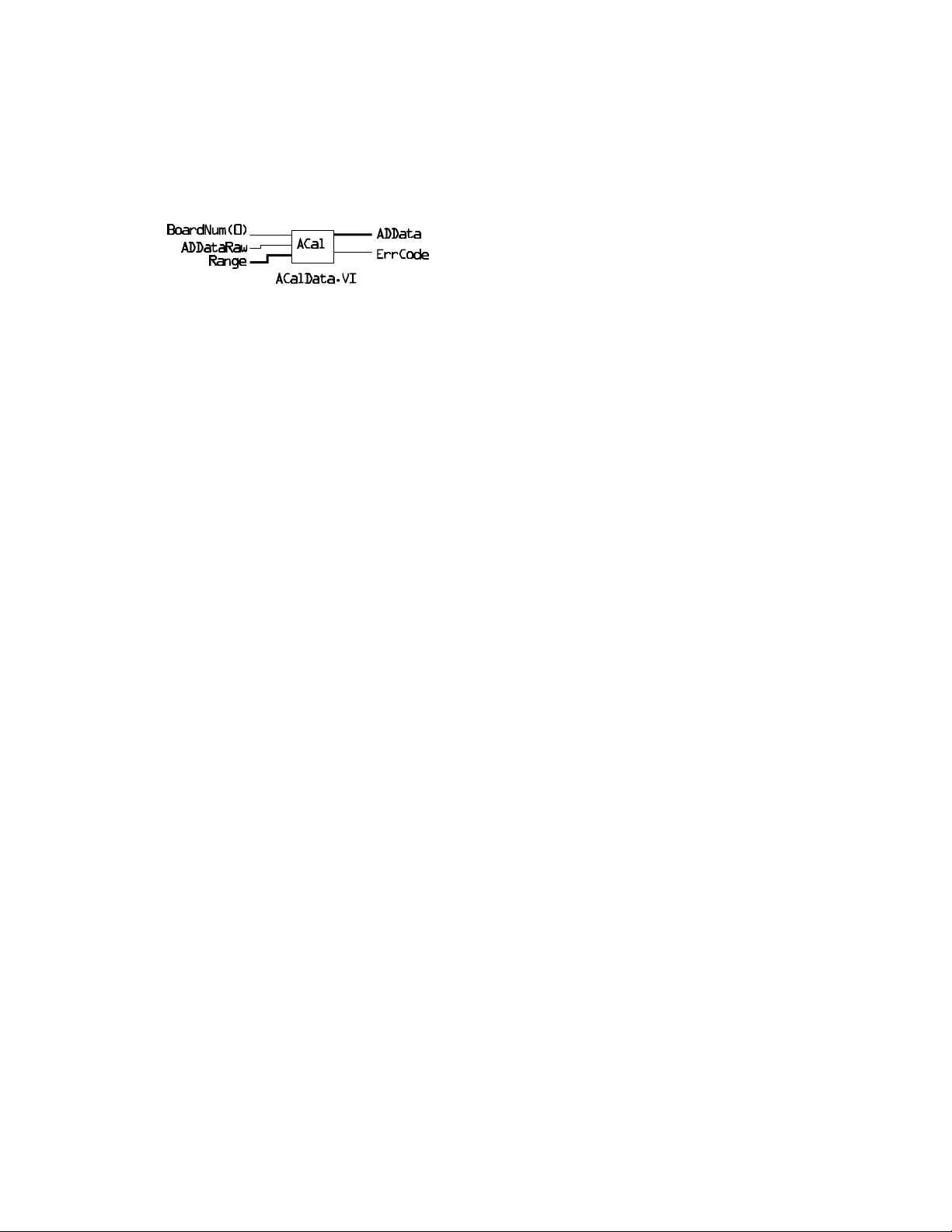
Inputs: BoardNum [U32] - The board number when installed with InstaCal. Can be 0 to 100.
Range [I32] - The programmable gain/range used when the data was collected
ADData [U16] - Pointer to data array
ADDataRaw [U16] - Raw A/D data
Outputs: ErrCode [I32] - Error code
Explanation of Arguments:
When you collect data with AInScxx and you use the NOCALIBRATEDATA option then you must use this VI to calibrate the data
after it is collected.
11
Page 16
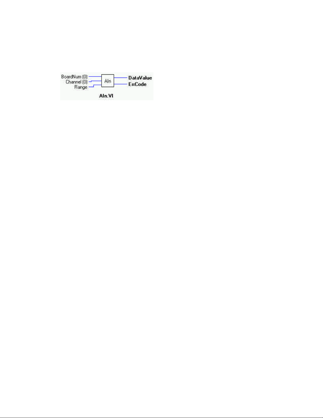
AIn.VI
Description:
Reads an A/D input channel. This VI reads the specified A/D channel from the specified board. If the A/D board has programmable
gain, it sets the gain to the specified range. The raw A/D value is converted to an A/D value and returned to DataValue.
Summary:
Inputs: BoardNum [U32] - The board number when installed with InstaCal. Can be 0 to 100.
Channel [I32] - A/D channel number
Range [I32]- A/D Range
Outputs: DataValue [U16] - Value of A/D sample
ErrCode [I32] - Error code
Explanation of the Arguments:
BoardNum - refers to the board number associated with the board when it was installed with the InstaCal™ configuration program.
The specified board must have an A/D.
Channel - The maximum allowable channel depends on which type of A/D board is being used. For boards that have both single
ended and differential inputs, the maximum allowable channel number also depends on how the board is configured. For example, a
CIO-DAS1600 has eight channels for differential, 16 for single-ended input mode.
Range - If the selected A/D board does not have a programmable gain feature, this argument is ignored. If the A/D board does have
programmable gain, set the Range argument to the desired A/D range. Not all A/D boards support the same A/D ranges. Refer to the
A/D board manual for a list of supported A/D Ranges.
BIP10VOLTS +/- 10 volts UNI10VOLTS 0 to 10 volts
BIP5VOLTS +/- 5 volts UNI5VOLTS 0 to 5 volts
BIP2PT5VOLTS +/- 2.5 volts UNI2PT5VOLTS 0 to 2.5 volts
BIP1PT67VOLTS +/- 1.67 volts UNI2VOLTS 0 to 2 volts
BIP1PT25VOLTS +/- 1.25 volts UNI1PT67VOLTS 0 to 1.67 volts
BIP1VOLTS +/- 1 volts UNI1PT25VOLTS 0 to 1.25 volts
BIPPT625VOLTS +/- 0.625 volts UNI1VOLTS 0 to 1 volts
BIPPT5VOLTS +/- 0.5 volts UNIPT1VOLTS 0 to 0.1 volts
BIPPT1VOLTS +/- 0.1 volts UNIPT01VOLTS 0 to 0.01 volts
BIPPT05VOLTS +/-0.05 volts MA4TO20 4 to 20 mA
BIPPT01VOLTS +/- 001 volts MA2TO10 2 to 10 mA
BIPPT005VOLTS +/- 0.005 volts MA1TO5 1 to 5 mA
MAPT5TO2PT5 0.5 to 2.5 mA
12
Page 17
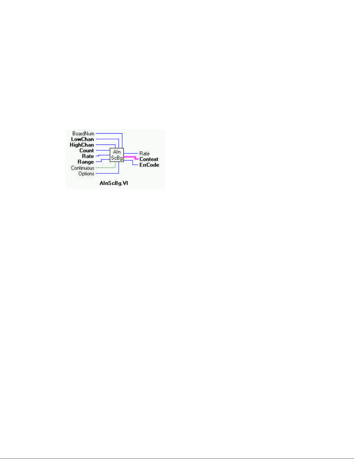
AInScBg.VI Changed R3.3 ID
Description:
Scans a range of A/D channels in the background and stores the samples in an array. This VI reads the specified number of A/D
samples at the specified sampling rate from the specified range of A/D channels from the specified board. If the A/D board has programmable gain, it sets the gain to the specified range. The collected data is returned to the data array. This VI immediately returns
control to your program and the data collection from the A/D into ADData will continue in the background. Use the GetStat VI to
check on the status of the background operation and to get data as it is being collected. Use the StopBg VI to terminate the background process before it has completed. Always execute the StopBg VI after any background operation has terminated normally to
clear variables and flags.
Revision 3.3 added no real-time calibration option. See OptAIn.VI for details.
Summary:
Inputs: BoardNum [U32] - The board number when installed with InstaCal. Can be 0 to 100.
LowChan [I32] - First A/D channel of scan
HighChan [I32] - Last A/D channel of scan
Count [I32] - Number of A/D samples to collect
Rate [I32]- Sample rate in scans per second
Range [I32]- A/D range code
Continuous [TF] - Run the VI in an endless loop
Options [I32] - Bit fields that control various options *NOTE 1
Outputs: Rate [I32] - Actual rate the board sampled
Context [cluster] - Output data structure *NOTE 2
ErrCode [I32] - Error Code
Explanation of the Arguments:
BoardNum - refers to the board number associated with the board when it was installed with the InstaCal configuration program.
The specified board must have an A/D.
Low / High Channel # - The maximum allowable channel depends on which type of A/D board is being used. For boards that have
both single ended and differential inputs the maximum allowable channel number also depends on how the board is configured. For
example, a CIO-DAS1600 has 8 channels for differential, 16 for single-ended.
Count - Specifies the total number of A/D samples that will be collected. If more than one channel is being sampled then the number
of samples collected per channel is equal to Count / (HighChan- LowChan+1).
Rate - This is the rate at which scans are triggered. If you are sampling four channels, 0-3, specifying a rate of 10,000 scans per second (10 kS/s) will result in the A/D converter rate of 40 kS/s: (4 channels at 10,000 samples per channel per second). This is different from some software where you specify the total A/D chip rate. In those systems, the per channel rate is equal to the A/D rate
13
Page 18

divided by the number of channels in a scan. This argument also returns the value of the actual rate set. This may be different from
the requested rate because of pacer limitations.
Caution: You will generate an error if you specify a total A/D rate beyond the capability of the board. For example; if you specify
LowChan = 0, HighChan = 7 (8 channels total) and Rate = 20,000 and you are using a CIO-DAS16/Jr, you will get an error. You
have specified a total rate of 8 x 20,000 = 160,000. The CIO-DAS16/Jr is capable of converting 120,000 samples per second. The
maximum sampling rate depends on the A/D board that is being used. It is also dependent on the sampling mode options.
Range - If the selected A/D board does not have a programmable range feature, this argument is ignored. Otherwise the gain can be
set to any of the following ranges that are supported by the selected A/D board. Refer to board-specific information for the list of
ranges supported by each board.
BIP10VOLTS +/- 10 volts UNI10VOLTS 0 to 10 volts
BIP5VOLTS +/- 5 volts UNI5VOLTS 0 to 5 volts
BIP2PT5VOLTS +/- 2.5 volts UNI2PT5VOLTS 0 to 2.5 volts
BIP1PT67VOLTS +/- 1.67 volts UNI2VOLTS 0 to 2 volts
BIP1PT25VOLTS +/- 1.25 volts UNI1PT67VOLTS 0 to 1.67 volts
BIP1VOLTS +/- 1 volts UNI1PT25VOLTS 0 to 1.25 volts
BIPPT625VOLTS +/- 0.625 volts UNI1VOLTS 0 to 1 volts
BIPPT5VOLTS +/- 0.5 volts UNIPT1VOLTS 0 to 0.1 volts
BIPPT1VOLTS +/- 0.1 volts UNIPT01VOLTS 0 to 0.01 volts
BIPPT05VOLTS +/-0.05 volts MA4TO20 4 to 20 mA
BIPPT01VOLTS +/- 001 volts MA2TO10 2 to 10 mA
BIPPT005VOLTS +/- 0.005 volts MA1TO5 1 to 5 mA
MAPT5TO2PT5 0.5 to 2.5 mA
CONTINUOUS - This option (True) puts the VI in an endless loop. After it collects the required number of samples, it resets to the
start of ADData and begins again. The only way to stop this operation is with StopBg VI.
Options - For a detailed explanation of the Options field, please refer to the OptAIn.VI section of this manual.
*NOTE 1: The OptAIn.VI must be wired to this input.
Context - Data structure containing information from a background operation. Some of the information included is the board number, the data array, the array size, and the initial status of the background operation.
*NOTE 2: Wiring of this VI should conform to the following pattern:
Ÿ AInScBg.VI starts a background operation.
Ÿ GetStat.VI checks for completion (boolean output called "Running").
Ÿ StopBg.VI terminates the operation, if not already done, and frees memory aliases.
Ÿ Data output from the background operation is passed to GetStat.VI and StopBg.VI via "Context" It can be wired from one
or both of them for intermediate or final actions, respectively. The demo VIS illustrate this process effectively.
VERY IMPORTANT NOTE
In order to understand the functions, please read the Board-Specific Information section found in the Universal
Library User's Guide. The example programs should be examined and run prior to attempting any programming of
your own.
14
Page 19
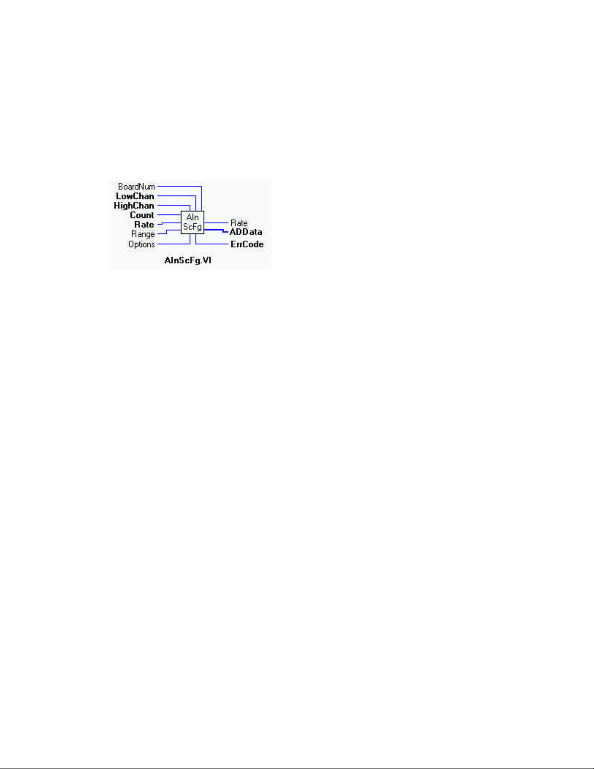
AInScFg.VI Changed R3.3 ID
Description:
Scans a range of A/D channels in the foreground and stores the samples in an array. This VI reads the specified number of A/D samples at the specified sampling rate from the specified range of A/D channels from the specified board. If the A/D board has programmable gain, it sets the gain to the specified range. The collected data is returned to the data array. This VI will not return control to
your program until all requested data has been collected and returned to ADData.
Revision 3.3 added 'no real time calibration' option. See Opt.AIn. VI for details.
Summary:
Inputs: BoardNum [U32] - The board number when installed with InstaCal. Can be 0 to 100.
LowChan [I32] - First A/D channel of scan
HighChan [I32] - Last A/D channel of scan
Count [I32] - Number of A/D samples to collect
Rate [I32] - Sample rate in scans per second
Range [I32]- A/D range code
Options [I32] - Bit fields that control various options *NOTE 1
Outputs: Rate [I32] - Actual rate the board sampled
ADData [U16] - Data array to store A/D values in
ErrCode [I32] - Error Code
Explanation of the Arguments:
BoardNum - refers to the board number associated with the board when it was installed with the InstaCal configuration program.
The specified board must have an A/D.
Low / High Channel # - The maximum allowable channel depends on which type of A/D board is being used. For boards that have
both single ended and differential inputs the maximum allowable channel number also depends on how the board is configured. For
example, a CIO-DAS1600 has 8 channels for differential, 16 for single-ended.
Count - Specifies the total number of A/D samples that will be collected. If more than one channel is being sampled then the number
of samples collected per channel is equal to Count / (HighChan- LowChan+1).
Rate - This is the rate at which scans are triggered. If you are sampling four channels, 0-3, then specifying a rate of 10,000 scans per
second (10 kS/s) will result in the A/D converter rate of 40 kS/s: (4 channels at 10,000 samples per channel per second). This is
different from some software where you specify the total A/D chip rate. In those systems, the per channel rate is equal to the A/D
rate divided by the number of channels in a scan. This argument also returns the value of the actual rate set. This may be different
from the requested rate because of pacer limitations.
Caution! You will generate an error if you specify a total A/D rate beyond the capability of the board. For example; if you specify
LowChan = 0, HighChan = 7 (8 channels total) and Rate = 20,000 and you are using a CIO-DAS16/Jr, you will get an error. You
have specified a total rate of 8 x 20,000 = 160,000. The CIO-DAS16/Jr is capable of converting 120,000 samples per second. The
maximum sampling rate depends on the A/D board that is being used. It is also dependent on the sampling mode options.
15
Page 20

Range - If the selected A/D board does not have a programmable range feature, then this argument will be ignored. Otherwise the
gain can be set to any of the following ranges that are supported by the selected A/D board. Refer to board specific information for
the list of ranges supported by each board.
BIP10VOLTS +/- 10 volts UNI10VOLTS 0 to 10 volts
BIP5VOLTS +/- 5 volts UNI5VOLTS 0 to 5 volts
BIP2PT5VOLTS +/- 2.5 volts UNI2PT5VOLTS 0 to 2.5 volts
BIP1PT67VOLTS +/- 1.67 volts UNI2VOLTS 0 to 2 volts
BIP1PT25VOLTS +/- 1.25 volts UNI1PT67VOLTS 0 to 1.67 volts
BIP1VOLTS +/- 1 volts UNI1PT25VOLTS 0 to 1.25 volts
BIPPT625VOLTS +/- 0.625 volts UNI1VOLTS 0 to 1 volts
BIPPT5VOLTS +/- 0.5 volts UNIPT1VOLTS 0 to 0.1 volts
BIPPT1VOLTS +/- 0.1 volts UNIPT01VOLTS 0 to 0.01 volts
BIPPT05VOLTS +/-0.05 volts MA4TO20 4 to 20 mA
BIPPT01VOLTS +/- 001 volts MA2TO10 2 to 10 mA
BIPPT005VOLTS +/- 0.005 volts MA1TO5 1 to 5 mA
MAPT5TO2PT5 0.5 to 2.5 mA
Options - For a detailed explanation of the Options field, please refer to the OPTAIN.VI section of this manual.
*NOTE 1: The OptAIn.VI must be wired to this input.
VERY IMPORTANT NOTE
In order to understand the functions, please read the Board-Specific Information section found in the Universal
Library User's Guide. The example programs should be examined and run prior to attempting any programming of
your own.
16
Page 21
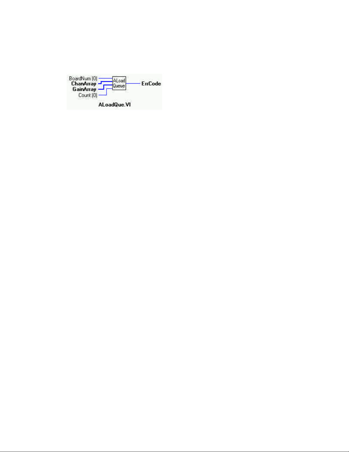
ALoadQue.VI
Description:
Loads A/D board's channel/gain queue. This VI only works with A/D boards that have channel/gain queue hardware.
Summary:
Inputs: BoardNum [U32] - The board number when installed with InstaCal. Can be 0 to 100.
ChanArray [I16] - Array containing channel values
GainArray [I16] - Array containing A/D range values
Count [I32] - Number of elements in ChanArray and GainArray, or (0) to disable the board's chan/gain queue.
Outputs: ErrCode [I32] - Error code
Explanation of the Arguments:
BoardNum - refers to the board number associated with the board when it was installed with the configuration program.
The specified board must have an A/D and a channel/gain queue.
ChanArray - This array should contain all of the channels that will be loaded into the channel gain queue.
GainArray - This array should contain each of the A/D ranges that will be loaded into the channel gain queue.
Count - Specifies the total number of chan/gain pairs that will be loaded into the queue. ChanArray and GainArray should contain at
least Count elements. Set Count=0 to disable the board's chan/gain queue. The maximum value is specific to the queue size of the
A/D boards channel gain queue.
Normally the AInScxx VI scans a fixed range of channels (from LowChan to HighChan) at a fixed A/D range. If you load the channel gain queue with this VI, all subsequent calls to AInScxx will cycle through the chan/range pairs that you have loaded into the
queue.
17
Page 22
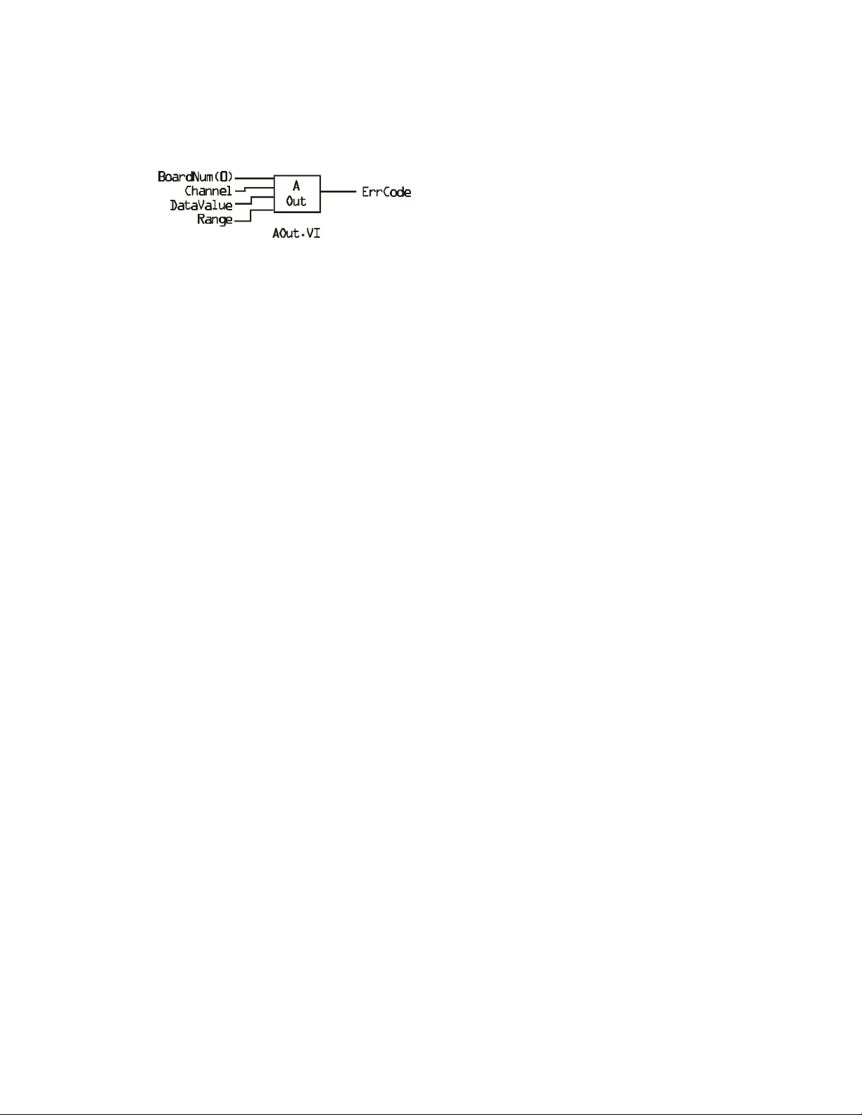
AOut.VI
Description:
Sets the value of a D/A output.
Summary:
Inputs: BoardNum [U32] - The board number when installed with InstaCal. Can be 0 to 100.
Channel [I32] - A/D channel number
DataValue [U16] - Value to set D/A to
Range [I32] - A/D Range code
Outputs: ErrCode [I32] - Error code
Explanation of the Arguments:
BoardNum - refers to the board number associated with the board when it was installed with the configuration program.
The specified board must have a D/A.
Channel - The maximum allowable channel depends on which type of D/A board is being used.
DataValue - Must be in the range 0 - N where N is the value 2 ^ Resolution - 1 of the converter.
Range - If the selected A/D board does not have a programmable range feature, this argument will be ignored. Otherwise the gain
can be set to any of the following ranges that are supported by the selected A/D board. Refer to board-specific information for the list
of ranges supported by each board.
BIP10VOLTS +/- 10 volts UNI10VOLTS 0 to 10 volts
BIP5VOLTS +/- 5 volts UNI5VOLTS 0 to 5 volts
BIP2PT5VOLTS +/- 2.5 volts UNI2PT5VOLTS 0 to 2.5 volts
BIP1PT67VOLTS +/- 1.67 volts UNI2VOLTS 0 to 2 volts
BIP1PT25VOLTS +/- 1.25 volts UNI1PT67VOLTS 0 to 1.67 volts
BIP1VOLTS +/- 1 volts UNI1PT25VOLTS 0 to 1.25 volts
BIPPT625VOLTS +/- 0.625 volts UNI1VOLTS 0 to 1 volts
BIPPT5VOLTS +/- 0.5 volts UNIPT1VOLTS 0 to 0.1 volts
BIPPT1VOLTS +/- 0.1 volts UNIPT01VOLTS 0 to 0.01 volts
BIPPT05VOLTS +/-0.05 volts MA4TO20 4 to 20 mA
BIPPT01VOLTS +/- 001 volts MA2TO10 2 to 10 mA
BIPPT005VOLTS +/- 0.005 volts MA1TO5 1 to 5 mA
MAPT5TO2PT5 0.5 to 2.5 mA
For Simultaneous-Update Boards: If you have set the simultaneous update jumper for simultaneous operation, you should use
AOutScan.VI for simultaneous update of multiple channels. AOut.VI always writes the D/A data then reads the D/A, which causes
the D/A output to be updated.
18
Page 23
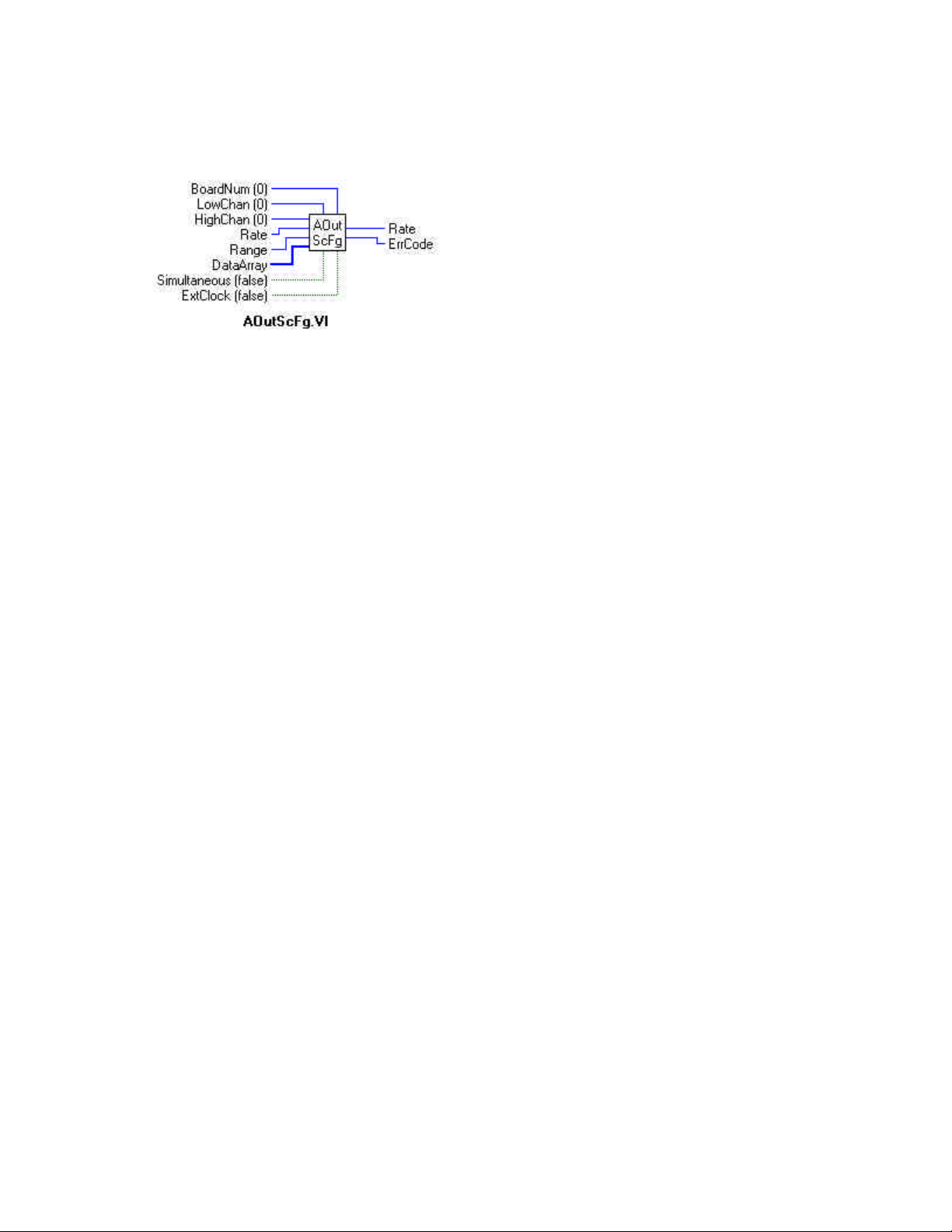
AOutScFg.VI
Description:
Outputs values to a range of D/A channels in the foreground.
Summary:
Inputs: BoardNum [U32] - The board number when installed with InstaCal. Can be 0 to 100.
LowChan [I32] - First D/A channel of scan
HighChan [I32] - Last D/A channel of scan
Rate [I32] - Sample rate in scans per second [U32]
Data Array [U16] - Data array to output D/A values from.
Simultaneous [TF] - Simultaneous update mode
Range [I32] - D/A range code
ExtClock [TF] - Pace conversions externally
Outputs: ErrCode [I32] -Error code from Universal Library. See ErrMsg.VI
Rate [I32] - Actual output rate in samples per second
Explanation of the Arguments:
BoardNum - refers to the board number associated with the board when it was installed with the configuration program.
The specified board must have a D/A.
LowChan/HighChan - The maximum allowable channel depends on which type of D/A board is being used.
Rate - Sample rate in scans per second. For many D/A boards the Rate is ignored and can be set to NOTUSED. For D/A boards with
trigger and transfer methods which allow fast output rates, such as the CIO-DAC04/12-HS, Rate should be set to the D/A output rate
(in scans/sec). This argument also returns the value of the actual rate set. This value may be different from the user specified rate
because of pacer limitations.
If supported, scans are triggered at this rate. If you are updating four channels, 0-3, specifying a rate of 10,000 scans per second (10
kS/s) will result in the D/A converter rates of 10 kS/s: (one D/A per channel). The data transfer rate will be 40,000 words per
second; (4 channels x 10,000 updates per scan).
The maximum update rate depends on the D/A board that is being used. It is also dependent on the sampling mode options.
DataArray - The data array should be filled with D/A values in the range 0 - N where N is the value 2 ^ Resolution-1 of the converter. There should be at least HighChan-LowChan+1 elements in the array.
Simultaneous - When this option is set (True) (if the board supports it and the appropriate switches are set on the board) all of the
D/A voltages will be updated simultaneously when the last D/A in the scan is updated. This generally means that all the D/A values
will be written to the board, then a read of a D/A address causes all D/As to be updated with new values simultaneously.
Range - If the selected D/A board does not have a programmable range feature, then this argument will be ignored. Otherwise the
gain can be set to any of the following ranges that are supported by the selected board. Refer to board specific information for the list
of ranges supported by each board.
19
Page 24

EXTCLOCK - If this option (True) is used, conversions will be paced by the signal on the trigger input line rather than by the inter nal pacer clock. Each conversion will be triggered on the appropriate edge of the trigger input signal (see board-specific info). When
this option is used, the Rate argument is ignored. The sampling rate is dependent on the trigger signal. Options for the board will
default to transfer types that allow the maximum conversion rate to be attained unless otherwise specified.
BIP10VOLTS +/- 10 volts UNI10VOLTS 0 to 10 volts
BIP5VOLTS +/- 5 volts UNI5VOLTS 0 to 5 volts
BIP2PT5VOLTS +/- 2.5 volts UNI2PT5VOLTS 0 to 2.5 volts
BIP1PT67VOLTS +/- 1.67 volts UNI2VOLTS 0 to 2 volts
BIP1PT25VOLTS +/- 1.25 volts UNI1PT67VOLTS 0 to 1.67 volts
BIP1VOLTS +/- 1 volts UNI1PT25VOLTS 0 to 1.25 volts
BIPPT625VOLTS +/- 0.625 volts UNI1VOLTS 0 to 1 volts
BIPPT5VOLTS +/- 0.5 volts UNIPT1VOLTS 0 to 0.1 volts
BIPPT1VOLTS +/- 0.1 volts UNIPT01VOLTS 0 to 0.01 volts
BIPPT05VOLTS +/-0.05 volts MA4TO20 4 to 20 mA
BIPPT01VOLTS +/- 001 volts MA2TO10 2 to 10 mA
BIPPT005VOLTS +/- 0.005 volts MA1TO5 1 to 5 mA
MAPT5TO2PT5 0.5 to 2.5 mA
20
Page 25
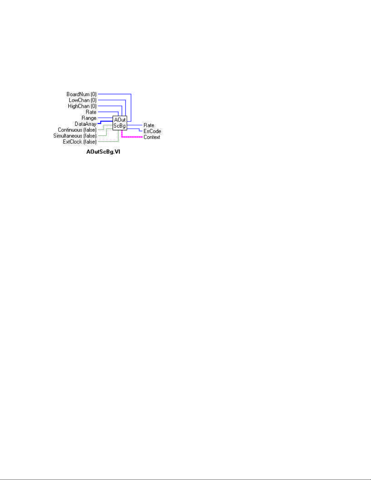
AOutScBg.VI
Description:
Outputs values to a range of D/A channels in the background. This VI can only be used with boards that support interrupt, DMA or
REP-INSW transfer methods. When this option is used the D/A operations will begin running in the background and control will
immediately return to the VI. Use GetStat.VI to check the status of background operation. Use StopBg.VI to terminate background
operations before they are completed. Always run StopBg.VI after running a background operation to clear variables and flags.
Summary:
Inputs: BoardNum [U32] - The board number when installed with InstaCal. Can be 0 to 100.
LowChan [I32] - First D/A channel of scan
HighChan [I32] - Last D/A channel of scan
Rate [I32] - Sample rate in scans per second
Range [I32] - D/A input range. If the selected D/A board does not have a programmable gain feature,. this argument is ignored. If the D/A board does have programmable gain, set the Range argument to the desired A/D range.
Not all A/D boards support the same D/A ranges. Refer to the board manual for a list of supported D/A Ranges.
DataArray [U16] - Data array to output D/A values from.
Continuous [TF] - Run the VI in an endless loop
Simultaneous [TF] - Simultaneous update
ExtClock [TF] - Pace conversions externally
Outputs: Error code. [I32] - Error code from Universal Library. See ErrMsg.VI
Context [cluster] - Data structure containing information from a background operation. Some of the information
included is the board number, the data array, the array size, and the initial status of the background operation.
Explanation of the Arguments:
BoardNum - refers to the board number associated with the board when it was installed with the configuration program. The specified board must have a D/A.
LowChan/HighChan - The maximum allowable channel depends on which type of D/A board is being used.
Rate - For D/A boards, the Rate is ignored and can be set to NOTUSED. For D/A boards with trigger, and transfer methods which
allow fast output rates, set Rate to the D/A output rate (in scans/sec). A typical fast board is the CIO-DAC04/12-HS
If supported, this is the rate at which scans are triggered. If you are updating 4 channels, 0-3, then specifying a rate of 10,000 scans
per second (10 kHz) will result in the D/A converter rates of 10 kHz: (one D/A per channel). The data transfer rate will be 40,000
words per second; (4 channels x 10,000 updates per scan).
The maximum update rate depends on the D/A board that is being used. It is also dependent on the sampling mode options.
DataArray - The data array should be filled with D/A values in the range 0 - N where N is the value 2 ^ Resolution-1 of the converter. There should be at least HighChan-LowChan+1 elements in the array.
Continuous - This option (True) can only be used with boards which support interrupt, DMA or REP-INSW transfer methods. This
option puts the VI in an endless loop. After it outputs the specified (by Count) number of D/A values, it resets to the start of DataArray and begins again. The only way to stop this operation is with StopBg.VI.
21
Page 26

EXTCLOCK - If this option (True) is used then conversions will be paced by the signal on the trigger input line rather than by the
internal pacer clock. Each conversion will be triggered on the appropriate edge of the trigger input signal (see board specific info).
When this option is used the Rate argument is ignored. The sampling rate is dependent on the trigger signal. Options for the board
will default to transfer types that allow the maximum conversion rate to be attained unless otherwise specified.
Range - If the selected D/A board does not have a programmable range feature, this will be ignored. Otherwise the gain can be set to
any of the following ranges that are supported by the selected D/A board. Refer to board-specific information for the list of ranges
supported by each board.
BIP10VOLTS +/- 10 volts UNI10VOLTS 0 to 10 volts
BIP5VOLTS +/- 5 volts UNI5VOLTS 0 to 5 volts
BIP2PT5VOLTS +/- 2.5 volts UNI2PT5VOLTS 0 to 2.5 volts
BIP1PT67VOLTS +/- 1.67 volts UNI2VOLTS 0 to 2 volts
BIP1PT25VOLTS +/- 1.25 volts UNI1PT67VOLTS 0 to 1.67 volts
BIP1VOLTS +/- 1 volts UNI1PT25VOLTS 0 to 1.25 volts
BIPPT625VOLTS +/- 0.625 volts UNI1VOLTS 0 to 1 volts
BIPPT5VOLTS +/- 0.5 volts UNIPT1VOLTS 0 to 0.1 volts
BIPPT1VOLTS +/- 0.1 volts UNIPT01VOLTS 0 to 0.01 volts
BIPPT05VOLTS +/-0.05 volts MA4TO20 4 to 20 mA
BIPPT01VOLTS +/- 001 volts MA2TO10 2 to 10 mA
BIPPT005VOLTS +/- 0.005 volts MA1TO5 1 to 5 mA
MAPT5TO2PT5 0.5 to 2.5 mA
Simultaneous- When this option is set (True) (if the board supports it and the appropriate switches are set on the board) all of the
D/A voltages will be updated simultaneously when the last D/A in the scan is updated. This generally means that all the D/A values
will be written to the board, then a read of a D/A address causes all D/As to be updated with new values simultaneously.
*NOTE 2:
Wiring of this VI should conform to the following pattern:
Ÿ AOutScBg.VI starts a background operation.
Ÿ GetStat.VI checks for completion (boolean output called "Running").
Ÿ StopBg.VI terminates the operation, if not already done, and frees memory aliases.
Ÿ Data output from the background operation is passed to GetStat.VI and StopBg.VI via "Context", and can be wired from
one or both of them for intermediate or final actions, respectively.
Ÿ The demo VIs illustrate this process effectively.
22
Page 27
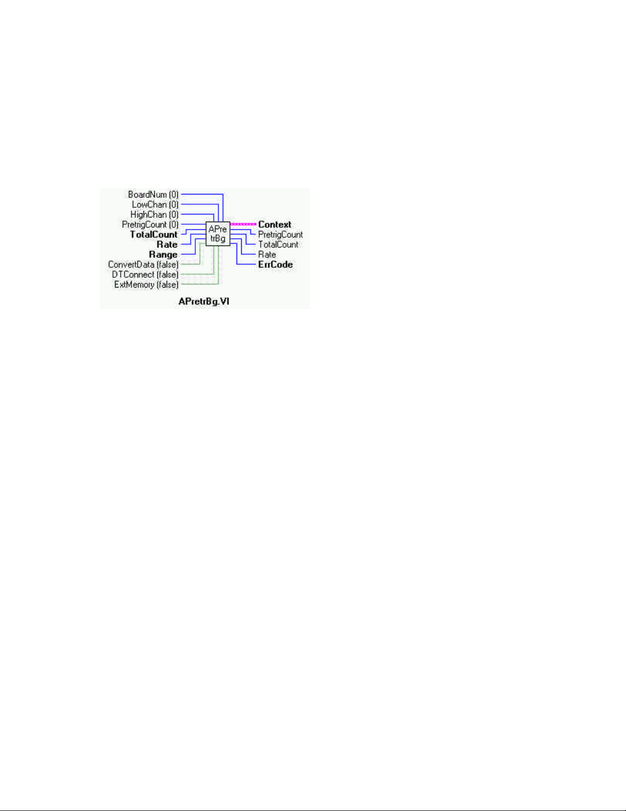
APretrBg.VI
Description:
Waits for a trigger to occur and then returns a specified number of analog samples before and after the trigger occurred. If only
'polled gate' triggering is supported, the trigger input line (see board user's manual) must be at TTL low before this VI is called or a
TRIGSTATE error will occur. The trigger occurs when the trigger condition is met. See SetTrig.VI and board-specific information.
After this VI is called, execution will return immediately to the next point in your program and the data collection from the A/D into
DataArray will continue in the background. Use GetStat.VI to check on the status of the background operation. Use StopBg.VI to
terminate the background process before or after it has completed its function .
Summary:
Inputs: BoardNum [U32] - The board number when installed with InstaCal. Can be 0 to 100.
LowChan [I32] - First A/D channel of scan
HighChan [I32] - Last A/D channel of scan
PretrigCount [I32] - Number of pre-trigger A/D samples to collect
TotalCount [I32] - Total number of A/D samples to collect
Rate [I32] - Sample rate in scans per second
Range [I32] - A/D Range code or 0
ConvertData [TF] - Convert data option (Boolean)
DTConnect [TF] - DT connect option (Boolean)
ExtMemory [TF] - External memory option (Boolean)
Outputs: Context [cluster] - Output data structure *NOTE
PretrigCount [I32] - Number of pre-trigger A/D samples collected
TotalCount [I32] - Total number of A/D samples collected
Rate [U32] - Actual sample rate in scans per second
ErrCode [I32] - Error code from Universal Library. See ErrMsg.VI
Explanation of the Arguments:
BoardNum - refers to the board number associated with the board when it was installed with the configuration program.
The specified board must have an A/D.
LowChan/HighChan - The maximum allowable channel depends on which type of A/D board is being used. For boards that have
both single ended and differential inputs the maximum allowable channel number also depends on how the board is configured
(8 channels for differential, 16 for single-ended).
PretrigCount - Specifies the number of samples before the trigger that will be returned. PretrigCount must be less than 32000 and
PretrigCount must also be less than TotalCount − 512. If the trigger occurs too early, then fewer than the requested number of pretrigger samples will be collected. In that case a TOOFEW error will occur. The PretrigCount will be set to indicate how many samples were collected and the post-trigger samples will still be collected.
23
Page 28

TotalCount - Specifies the total number of samples that will be collected and stored in DataArray. TotalCount must be greater than
or equal to PretrigCount + 512. If the trigger occurs too early then fewer than the requested number of samples will be collected. In
that case a TOOFEW error will occur. The TotalCount will be set to indicate how many samples were actually collected.
Range - If the selected A/D board does not have a programmable gain feature, this argument will be ignored. Otherwise the Range
can be set to any of the following ranges that are supported by the selected A/D board. Refer to board specific information for a list of
the A/D ranges supported by each board.
BIP10VOLTS +/- 10 volts UNI10VOLTS 0 - 10 volts
BIP5VOLTS +/- 5 volts UNI5VOLTS 0 - 5 volts
BIP2PT5VOLTS +/- 2.5 volts UNI2PT5VOLTS 0 - 2.5 volts
BIP1PT67VOLTS +/- 1.67 volts UNI2VOLTS 0 - 2 volts
BIP1PT25VOLTS +/- 1.25 volts UNI1PT67VOLTS 0 - 1.67 volts
BIP1VOLTS +/- 1 volts UNI1PT25VOLTS 0 - 1.25 volts
BIPPT625VOLTS +/- 0.625 volts UNI1VOLTS 0 - 1 volts
BIPPT5VOLTS +/- 0.5 volts UNIPT1VOLTS 0 - 0.1 volts
BIPPT1VOLTS +/- 0.1 volts UNIPT01VOLTS 0 - 0.01 volts
BIPPT05VOLTS +/-0.05 volts MA4TO20 4 - 20 mA
BIPPT01VOLTS +/- 001 volts MA2TO10 2 - 10 mA
BIPPT005VOLTS +/- 0.005 volts MA1TO5 1 - 5 mA
MAPT5TO2PT5 0.5 - 2.5 mA
DTConnect - When DTCONNECT option (True) is used with this VI, the data from ALL A/D conversions is sent out the DTCONNECT interface. While this VI is waiting for a trigger to occur, it will send data out the DT-CONNECT interface continuously.
If you have a OMEGA memory board plugged into the DT-CONNECT interface then you should use EXT MEMORY option rather than this option.
ExtMemory - If you use this option (True) to send the data to a connected memory board then you must use MemRdPrt.VI to later
read the pre-trigger data from the memory board. If you use MemRead.VI, the data will NOT be in the correct order. Every time this
option is used it will overwrite any data that is already stored in the memory board. Read all data from the board (with
MemRdPrt.VI) before collecting any new data. The Mega Fifo memory must be fully populated to use the APretr##.VI.
ConvertData - Set this option to FALSE (default) when using APretrBg.
Context - The data array for the pretrigger data. This is a data structure containing output information including the board number,
the contents of DataArray, the size of DataArray, and the initial status of the background operation. This CONTEXT must be wired
to subsequent VIs in order to process this VI correctly.
*NOTE:
Wiring of this VI should conform to the following pattern:
Ÿ APretrBg.VI starts a background operation.
Ÿ GetStat.VI checks for completion (boolean output called "Running").
Ÿ StopBg.VI terminates the operation, if not already done, and frees memory aliases.
Ÿ Data output from the background operation is passed to GetStat.VI and StopBg.VI via "Context", and can be wired from
one or both of them for intermediate or final actions, respectively.
Ÿ The demo VIs illustrate this process effectively.
24
Page 29
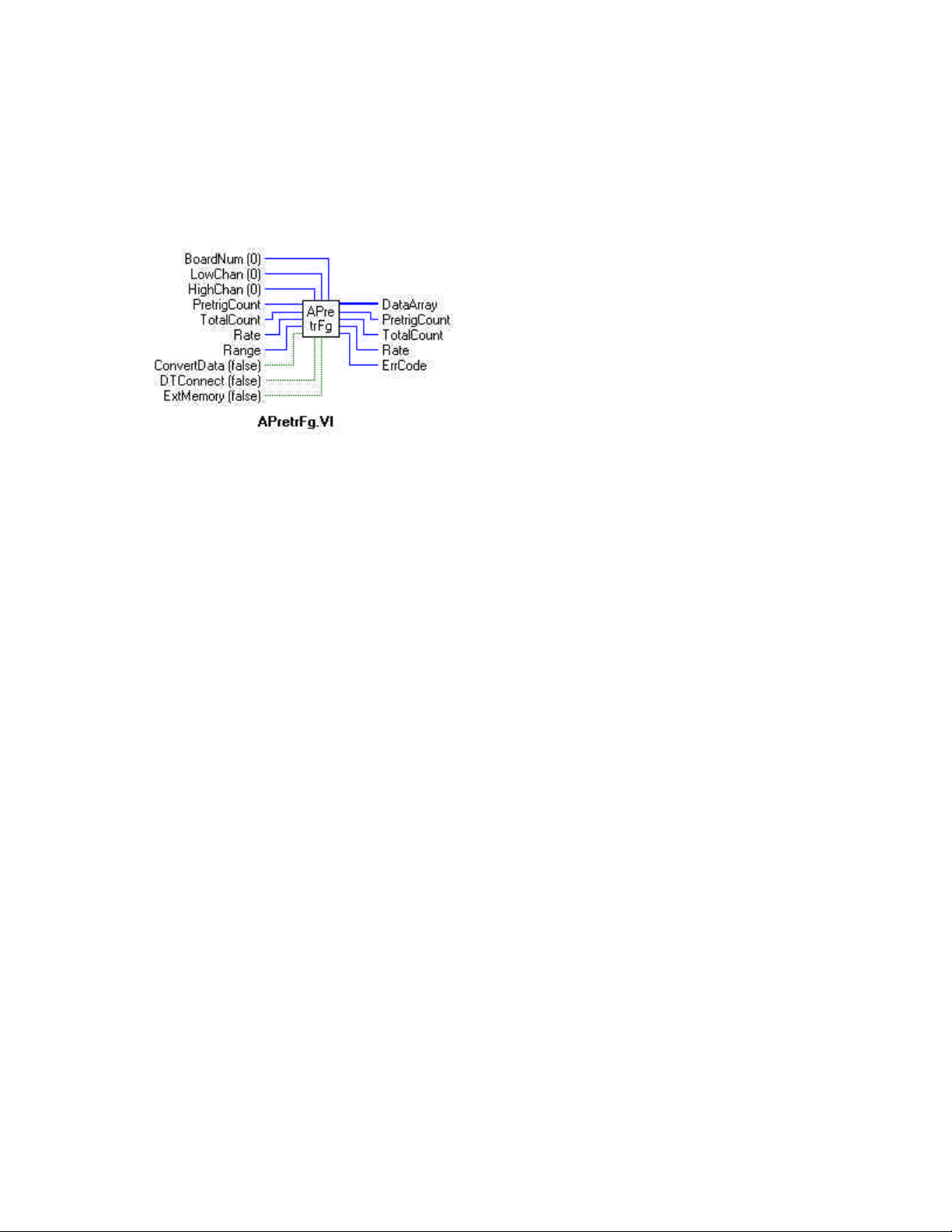
APretrFg.VI
Description:
Waits for a trigger to occur and then returns a specified number of analog samples before and after the trigger occurred. If only
'polled gate' triggering is supported, the trigger input line (see board user's manual) must be at TTL low before this VI is called or a
TRIGSTATE error will occur. The trigger occurs when the trigger condition is met. See SetTrig and board-specific information for
details. This VI will not return to your program until all of the requested data has been collected and returned to DataArray.
Summary:
Inputs: BoardNum [U32] - The board number when installed with InstaCal. Can be 0 to 100.
LowChan [I32] - First A/D channel of scan
HighChan [I32] - Last A/D channel of scan
PretrigCount [I32] - Number of pre-trigger A/D samples to collect
TotalCount [I32] - Total number of A/D samples to collect
Rate [U32] - Sample rate in scans per second
Range [I32] - A/D Range code or 0
ConvertData [TF] - Convert data option (Boolean)
DTConnect [TF] - DT connect option(Boolean)
ExtMemory [TF] - External memory option(Boolean)
Outputs: DataArray [U32] - Data array to store A/D values in.
PretrigCount [I32]- Number of pre-trigger A/D samples collected
TotalCount [I32] - Total number of A/D samples collected
Rate [U32] - Actual sample rate in scans per second
ErrCode [I32] - Error code from Universal Library. See ErrMsg.VI
Explanation of the Arguments:
BoardNum - refers to the board number associated with the board when it was installed with the configuration program. The specified board must have an A/D.
LowChan/HighChan - The maximum allowable channel depends on which type of A/D board is being used. For boards that have
both single ended and differential inputs the maximum allowable channel number also depends on how the board is configured
(8 channels for differential, 16 for single-ended).
PretrigCount - Specifies the number of samples before the trigger that will be returned. PretrigCount must be less than 32000 and
PretrigCount must also be less than TotalCount − 512. If the trigger occurs too early, fewer than the requested number of pre-trigger
samples will be collected. In that case a TOOFEW error will occur. The PretrigCount will be set to indicate how many samples were
collected and the post trigger samples will still be collected.
TotalCount specifies the total number of samples that will be collected and stored in ADData. TotalCount must be greater than or
equal to PretrigCount + 512. If the trigger occurs too early then fewer than the requested number of samples will be collected. In that
case, a TOOFEW error will occur. The TotalCount will be set to indicate how many samples were actually collected.
25
Page 30

Range - If the selected A/D board does not have a programmable gain feature, this argument is ignored. Otherwise the Range can be
set to any of the following ranges that are supported by the selected A/D board. Refer to board-specific information for a list of the
A/D ranges supported by each board.
BIP10VOLTS +/- 10 volts UNI10VOLTS 0 to 10 volts
BIP5VOLTS +/- 5 volts UNI5VOLTS 0 to 5 volts
BIP2PT5VOLTS +/- 2.5 volts UNI2PT5VOLTS 0 to 2.5 volts
BIP1PT67VOLTS +/- 1.67 volts UNI2VOLTS 0 to 2 volts
BIP1PT25VOLTS +/- 1.25 volts UNI1PT67VOLTS 0 to 1.67 volts
BIP1VOLTS +/- 1 volts UNI1PT25VOLTS 0 to 1.25 volts
BIPPT625VOLTS +/- 0.625 volts UNI1VOLTS 0 to 1 volts
BIPPT5VOLTS +/- 0.5 volts UNIPT1VOLTS 0 to 0.1 volts
BIPPT1VOLTS +/- 0.1 volts UNIPT01VOLTS 0 to 0.01 volts
BIPPT05VOLTS +/-0.05 volts MA4TO20 4 to 20 mA
BIPPT01VOLTS +/- 001 volts MA2TO10 2 to 10 mA
BIPPT005VOLTS +/- 0.005 volts MA1TO5 1 to 5 mA
MAPT5TO2PT5 0.5 to 2.5 mA
DataArray - The data array for the pretrigger data.
ConvertData - The data is collected into a "circular" buffer. When the data collection is complete, the data is in the wrong order. If
using the CONVERTDATA option (True), when data acquisition is complete, the data is automatically rotated into the correct order
and converted to 12-bit values. Otherwise, you must call ACnvPrDt.VI to rotate the data.
DTConnect - When DTCONNECT option (True) is used with this VI , the data from ALL A/D conversions is sent out the DTCONNECT interface. While this VI is waiting for a trigger to occur, it will send data out the DT-CONNECT interface continuously.
If you have a OMEGA memory board plugged into the DT-CONNECT interface then you should use EXT MEMORY option rather than this option.
ExtMemory - If using this option (True) to send the data to a connected memory board, you must use MemRdPrt.VI to read the pretrigger data from the memory board later. If you use MemRead.VI, the data will NOT be in the correct order. Everytime this option
is used it will overwrite any data that is already stored in the memory board. All data should be read from the board (with
MemRdPrt.VI before collecting any new data. The Mega-Fifo memory must be fully populated to use the APretr##.VI.
26
Page 31
ATrigger.VI
Description:
Waits for a specified analog input channel to go above or below a specified value. This VI continuously reads the specified channel
and compares its value to TrigValue. Depending on whether TrigType is ABOVE or BELOW it waits for the first A/D sample that is
above or below TrigValue. It returns the first sample that meets the trigger criteria to DataValue.
Summary:
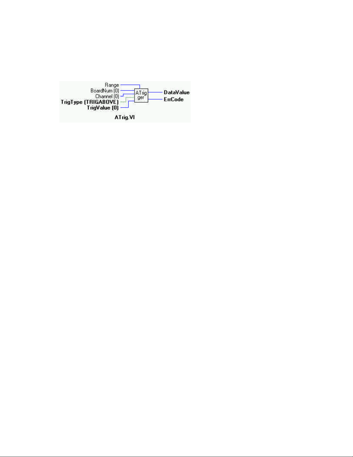
Inputs: BoardNum [U32] - The board number when installed with InstaCal. Can be 0 to 100.
Channel [I32] - A/D channel number
TrigType [TF] - TRIGABOVE (True) or TRIGBELOW (False) - Specifies whether waiting for the analog input
to be ABOVE or BELOW the specified trigger value.
TrigValue [I32] - The threshold value that all A/D values are compared to
Outputs: DataValue [U16] - The value of the first A/D sample that met the trigger criteria is returned here.
ErrCode [I32] - Error code from Universal Library TM see ErrMsg.VI
Explanation of the Arguments:
BoardNum - refers to the board number associated with the board when it was installed with the configuration program. The specified board must have an A/D.
Channel - The maximum allowable channel depends on which type of A/D board is being used. For boards that have both single
ended and differential inputs the maximum allowable channel number also depends on how the board is configured. For example a
CIO-DAS1600 has 8 channels for differential, 16 for single-ended.
TrigValue - Must be in the range 0 to 4095 for 12-bit A/D boards, or 0 to 65,535 for 16-bit A/D boards.
Windows Caution - Use this VI with caution in Windows programs. All active windows will be locked on the screen until the trigger condition is satisfied. All keyboard and mouse actions will also be locked until the trigger condition is satisfied.
27
Page 32

5.1 COUNTERS - AN INTRODUCTION
Universal Library LabVIEW Extensions provide VIs for initialization and configuration of counter chips. It is important to note
what this means:
VIs can configure a counter for any of the counters operations.
Counter configuration does not include USE of counters such as event counting and pulse width. Counter use is accomplished by
programs which use the counter VIs. Some counter-use VIs are available.
For you to use a counter for any but the simplest counting VI, you must use the information contained in the chip manufacturer's
data sheet. Technical support of the VIs does not include providing, interpreting or explaining the counter chip data sheet.
82C54
Counter chip data sheets are available, please consult engineering
AM9513
Call OMEGA Tech Support
(508)946-5100
Z8536
As of this writing, the only OMEGA board that employs the Z8536 is the CIO-INT32. The data book for the chip is
included with the CIO-INT32.
LS7266
US Digital
http://www.usdigital.com
5.2 COUNTER CHIP VARIABLES
Universal Library counter initialization and configuration VIs include names for bit patterns, such as ALEGATE, which stands for
Active Low Enabled Gate N. In any case where Universal Library has a name for a bit pattern, it is allowed to substitute the bit pattern as a numeric. This will work, but your programs will be more difficult to read and debug.
28
Page 33
C8254Cfg.VI
Description:
Configures 8254 counter for desired operation. This VI can only be used with 8254 counters.
Summary:
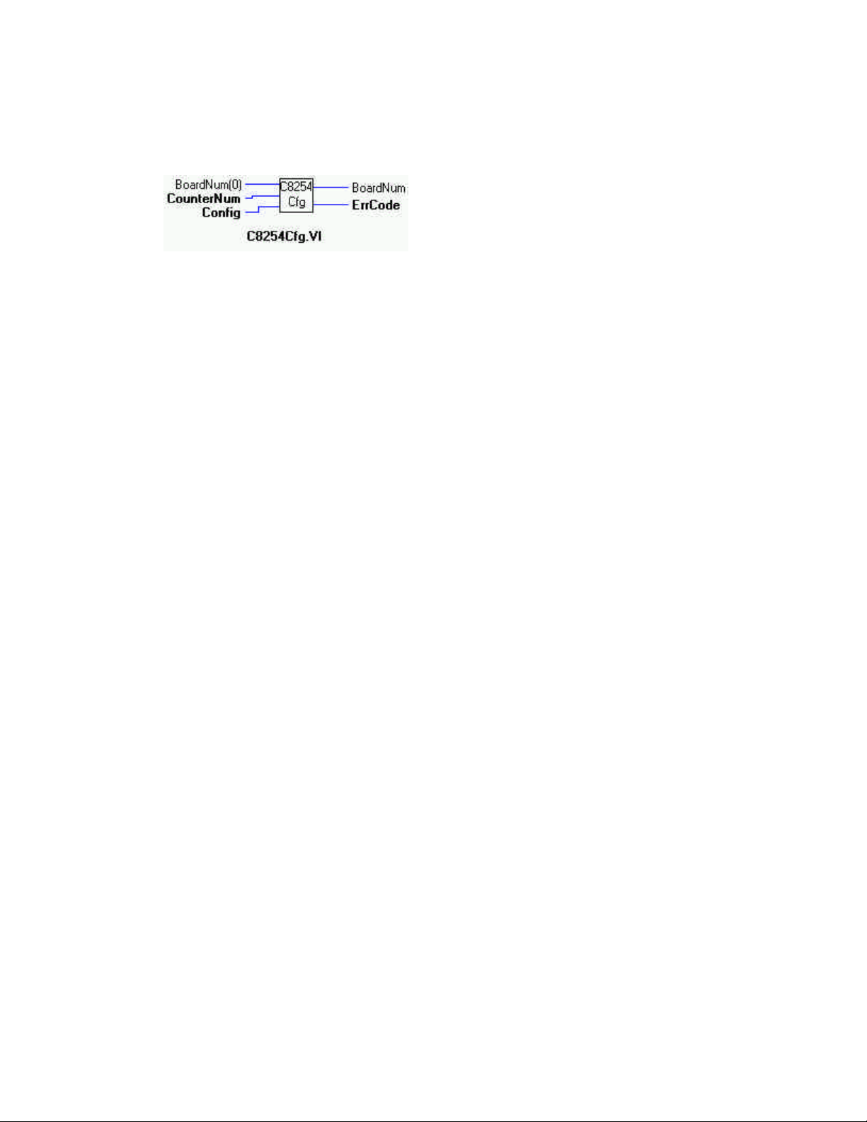
Inputs: BoardNum [U32] - The board number when installed with InstaCal. Can be 0 to 100.
CounterNum [U32] - counter number to configure
Config [U32] - the action to take on terminal count and the waveform if any.
Outputs: BoardNum (Out) [U32] - The board number when installed with InstaCal. Can be 0 to 100. Can be used to pass the
BoardNum parameter to another VI.
ErrCode [U32] - Error code Error code from Universal Library TM see ErrMsg.VI
Explanation of the Arguments:
BoardNum - refers to the board number associated with the board when it was installed with the configuration program. The specified board must have an 8254 counter.
CounterNum - Selects one of the counter channels. An 8254 has 3 counters. The value can be 1 - n, where n is the number of 8254
counters on the board (see board-specific info).
Config - Refer to the 8254 data sheet for a detailed description of each of the configurations. It can be set to one of the following con stants:
HIGHONLASTCOUNT: Output of counter (OUT N) transitions from low to high on terminal count and remains
high until reset. See Mode 0 on 8254 data sheet.
ONESHOT: Output of counter (OUT N) transitions from high to low on rising edge of GATE N, then back to high
on terminal count. See mode 1 on 8254 data sheet.
RATEGENERATOR: Output of counter (OUT N) pulses low for one clock cycle on terminal count and reloads the
counter and recycles. See mode 2 on 8254 data sheet.
SQUAREWAVE : Output of counter (OUT N) is high for count < 1/2 terminal count then low until terminal
count, whereupon it recycles. This mode generates a square wave. See mode 3 on 8254 data sheet.
SOFTWARESTROBE : Output of counter (OUT N) pulses low for one clock cycle on terminal count. Count starts
after counter is loaded. See mode 4 on 8254 data sheet.
HARDWARESTROBE : Output of counter (OUT N) pulses low for one clock cycle on terminal count. Count starts
on rising edge at GATE N input. See mode 5 on 8254 data sheet.
29
Page 34
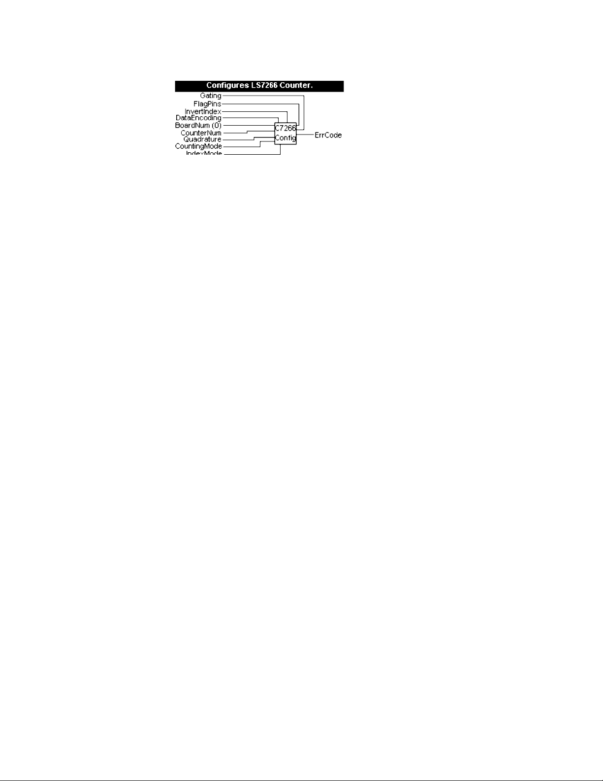
CBC7266Config()
Description:
Configures 7266 counter for desired operation. This function can only be used with boards that contain a 7266 counter chip (Quadrature Encoder boards).
Summary: int cbC7266Config (int BoardNum, int CounterNum, int Quadrature, int CountingMode, int DataEncoding, int
IndexMode, int InvertIndex, int FlagPins, int Gating);
Arguments: BoardNum [U32] - The board number when installed with InstaCal. Can be 0 to 100.
CounterNum [I32] - Counter number (1 − n) to configure
Quadrature [I32] - NO_QUAD, X1_QUAD, X2_QAUD or X4_QUAD
CountingMode [I32] - NORMAL_MODE, RANGE_LIMIT, NO_RECYCLE, MODULO_N
DataEncoding [I32] - BCD_ENCODING, BINARY_ENCODING
IndexMode [I32] - INDEX_DISABLED, LOAD_CTR, LOAD_OUT_LATCH, RESET_CTR
InvertIndex [I32] - DISABLED or ENABLED
FlagPins [I32] - Selects function for X1FLG and X2FLG pins. CARRY_BORROW, COMPARE_BORROW,
CARRYBORROW_UPDOWN, INDEX_ERROR.
Gating [TF] - DISABLED or ENABLED
Explanation of the Arguments:
BOARDNUM - Refers to the board number associated with the board when it was installed with the configuration program. The
specified board must have an LS7266 counter.
COUNTERNUM - Counter Number (1 − n) where n is the number of counters on the board. A PCM-CTR02 or ISA-CTR02 has two
counters. An ISA-QUAD04 has four counters.
QUADRATURE - Selects the resolution multiplier (X1_QUAD, X2_QUAD, or X4_QUAD) for quadrature input or disables quadrature input (NO_QUAD) so that the counters can be used as standard TTL counters.
COUNTINGMODE - Selects operating mode for the counter.
NORMAL_MODE - Each counter operates as a 24 bit counter that rolls over to 0 when the maximum count is reached.
RANGE_LIMIT - In range limit count mode, an upper an lower limit is set, mimicking limit switches in the mechanical
counterpart. The upper limit is set by loading the PRESET register with the cbCLoad function after the counter has been
configured.. The lower limit is always 0. When counting up, the counter freezes whenever the count reaches the value that
was loaded into the PRESET register. When counting down, the counter freezes at 0. In either case the counting is resumed
only when the count direction is reversed.
NO_RECYCLE - In non-recyle mode, the counter is disabled whenever a count overflow or underflow takes place. The
counter is re-enabled when a reset or load operation is performed on the counter.
MODULO_N - In modulo-n mode, an upper limit is set by loading the PRESET register with a maximum count. Whenever counting up, when the maximum count is reached, the counter will roll-over to 0 and continue counting up. Likewise
when counting down, whenever the count reaches 0, it will roll over to the maximum count (in the PRESET register) and
continue counting down.
30
Page 35

DATAENCODING - Selects the format of the data that is returned by the counter - either Binary or BCD format.
INDEXMODE - Selects which action will be taken when the Index signal is received. The IndexMode must be set to INDEX_DISABLED whenever a Quadrature is set to NON_QUAD or when Gate is set to ENABLED.
INDEX_DISABLED - The Index signal is ignored
LOAD_CTR - The counter is loaded whenever the Index signal ON the LCNTR pin occurs
LOAD_OUT_LATCH - The current count is latched whenever the Index signal on the LCNTR pin occurs. When this mode is
selected, The CIn() function will return the same count each time it is called until the Index signal occurs.
RESET_CTR - The counter is reset to 0 whenever the Index signal on the RCNTR pin occurs
INVERTINDEX - Selects the polarity of the Index signal. If set to DISABLED the Index signal is assumed to be positive polarity. If
set to ENABLED the Index signal is assumed to be negative polarity.
FLAGPINS - Selects which signals will be routed to the FLG1 and FLG2 pins.
CARRY_BORROW - FLG1 pin is CARRY output, FLG2 is BORROW output
COMPARE_BORROW - FLG1 pin is COMPARE output, FLG2 is BORROW output
CARRYBORROW_UPDOWN - FLG1 pin is CARRY/BORROW output, FLG2 is UP/DOWN signal
INDEX_ERROR - FLG1 is INDEX output, FLG2 is error output
GATING - If gating is set to ENABLED (True), the RCNTR pin will be used as a gating signal for the counter. Whenever
Gating=ENABLED, the IndexMode must be set to DISABLE_INDEX.
Returns: Error code or 0 if no error occurs.
31
Page 36
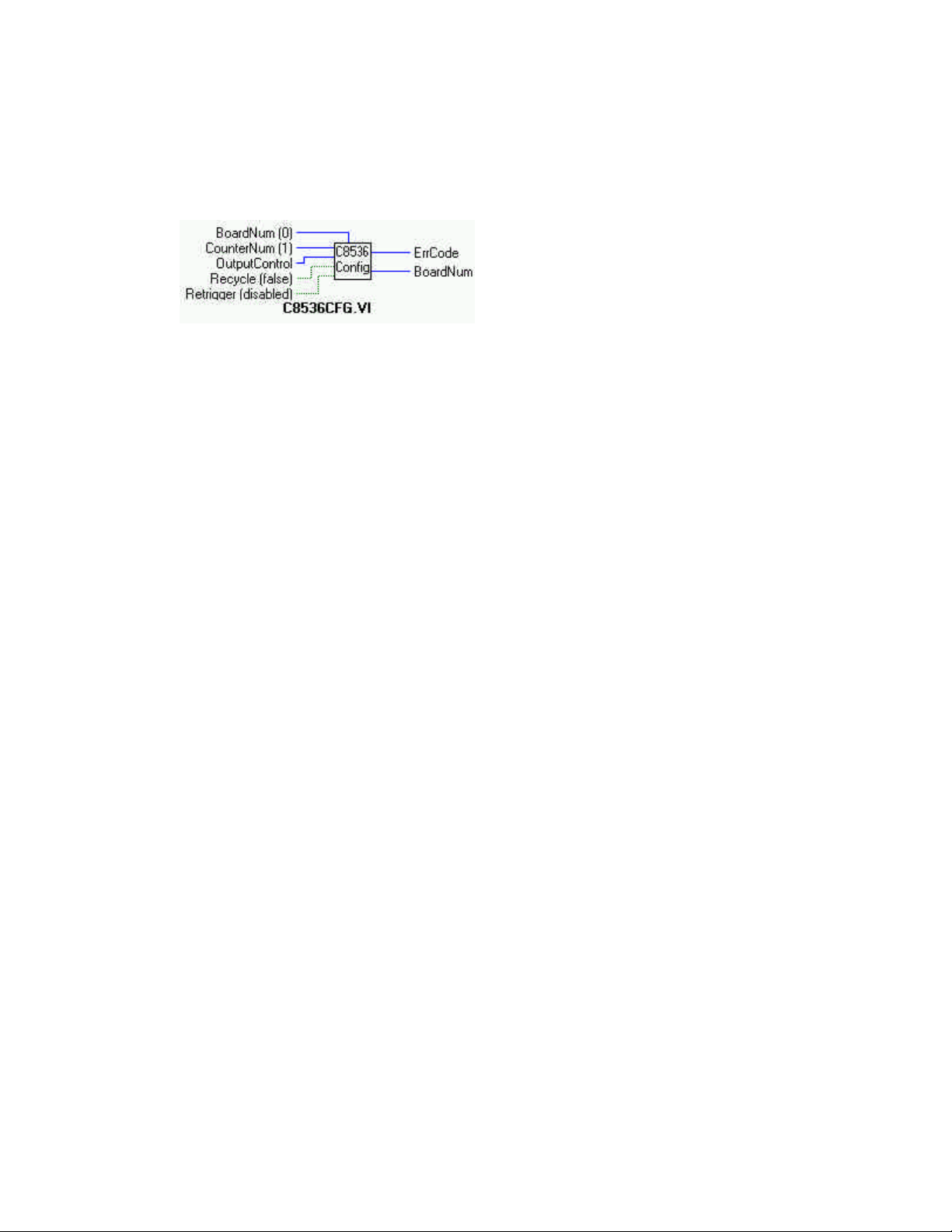
C8536Cfg.VI
Description:
Configures 8536 counter for desired operation. This VI can only be used with 8536 counters.
Summary:
Inputs: BoardNum [U32] - The board number when installed with InstaCal. Can be 0 to 100.
CounterNum [U32] - counter number to configure
OutputControl [U32] - Specifies counter output signal used.
Recycle [TF] - Execute once or reload and re-execute until stopped.
Retrigger [TF] - Enable or disable retriggering.
Outputs: ErrCode [I32] - Error code
BoardNum [U32] - Board number
Explanation of the Arguments:
BoardNum - refers to the board number associated with the board when it was installed with the configuration program. The speci-
fied board must have an A/D.
CounterNum - Selects one of the counter channels. An 8536 has 3 counters. The value can be 1 - n where n is the number of 8536
counters on the board (see board specific info).
OutputControl - Specifies the action of the output signal. The options for this argument are:
HIGHPULSEONTC - Output will transition from low to high for one clock pulse on terminal count.
TOGGLEONTC - Output will change state on terminal count.
HIGHUNTILTC - Output will transition to high at the start of counting then go low on terminal count.
RecycleMode - If set to RECYCLE (False, as opposed to ONETIME), the counter will automatically reload to the starting count
every time it reaches 0, then continue counting.
Retrigger - If set to ENABLED (True), every trigger on the counter's trigger input will initiate loading of the initial count. Counting
will proceed from initial count.
32
Page 37
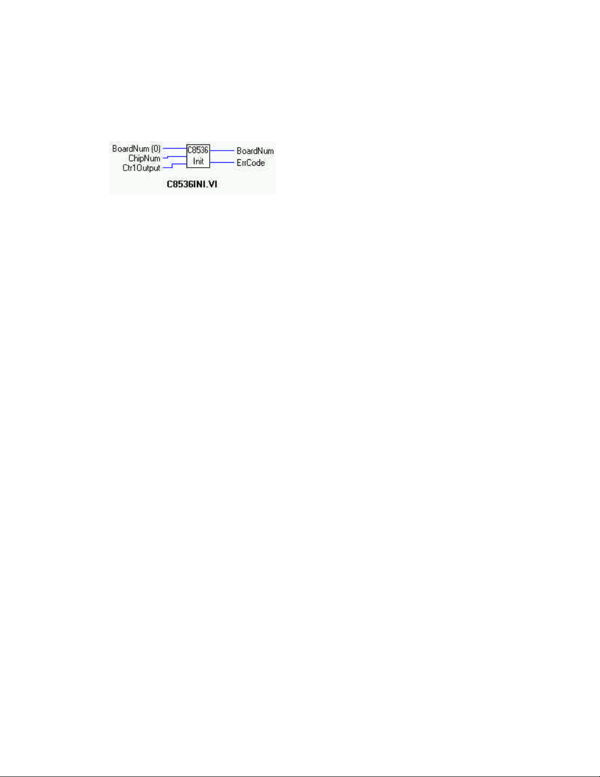
C8536Init.VI
Description:
Initializes the counter linking features of an 8536 counter chip. See the 8536 data sheet, Counter/Timer Link Controls section , for a
complete description of the hardware affected by this mode. Counters 1 and 2 must be linked before enabling the counters.
Summary:
Inputs: BoardNum [U32] - The board number when installed with InstaCal. Can be 0 to 100.
.
ChipNum [U32] - chip number to configure
CtrlOutput [U32] - Specifies counter output signal used.
Outputs: ErrCode [I32] - Error code
BoardNum [U32] - Board number
Explanation of the Arguments:
BoardNum - Board number of board with 8536 counter installed.
ChipNum - Selects one of the 8536 chips on the board, 1 to n.
CtrlOutput - Specifies how the counter 1 is to be linked to counter 2, if at all. The options for this argument are:
NOTLINKED -Counter 1 is not connected to any other counters inputs.
GATECTR2 - Output of counter 1 is connected to the GATE of counter #2.
TRIGCTR2 - Output of counter 1 is connected to the trigger of counter #2.
INCTR2 - Output of counter 1 is connected to counter #2 clock input.
33
Page 38
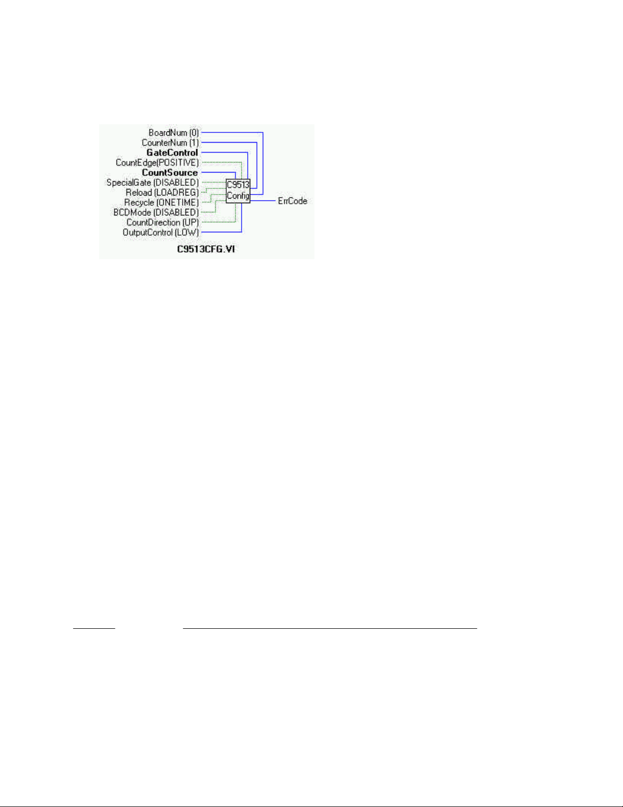
C9513Config.VI
Description:
Sets all of the configurable options of a 9513 counter.
Summary:
Inputs: BoardNum [U32] - The board number when installed with InstaCal. Can be 0 to 100.
CounterNum [U32] - counter number (1 - n)
GateControl [U32] - gate control
CountEdge [TF] - which edge to count
CountSource [U32] - which of the available count sources to use.
SpecialGate [TF] - special gate can be enabled or disabled.
Reload [TF] - Load or load and hold.
Recycle [TF] - Execute once or reload and recycle.
BCDMode [TF] - Counter can operate in Binary Coded Decimal if desired.
CountDirection [TF]- AM9513 can count up or down.
OutputControl [U32] - The type of output desired.
Outputs: ErrCode [I32] - Error Code
Explanation of the Arguments:
ADVICE: The information provided here and in C9513Ini will only help you understand how Universal Library syntax corresponds
to the 9513 data sheet. It is not a substitute for the data sheet. You cannot program a 9513 without the manufacturers' data book.
BoardNum - refers to the board number associated with the board when it was installed with the configuration program. The specified board must have a 9513 counter.
CounterNum - counter number (1 − n) where n is the number of counters on the board. (For example, a CIO-CTR5 has 5, a CIOCTR10 has 10, etc. See board-specific info).
GateControl - gate control variables are:
VI Syntax Corresponds to 9513 description in Counter Mode Register Description
NOGATE No gating
AHLTCPREVCTR Active high TCN-1
AHLNEXTGATE Active High Level GATE N + 1
AHLPREVGATE Active High Level GATE N - 1
AHLGATE Active High Level GATE N
ALLGATE Active Low Level GATE N
AHEGATE Active High Edge GATE N
ALEGATE Active Low Edge GATE N
34
Page 39

CountEdge - which edge to count. Refered to Source Edge in 9513 data book.
VI Syntax Corresponds to 9513 description in Counter Mode Register Description
POSITIVEEDGE Count on Rising Edge (False)
NEGATIVEEDGE Count on Falling Edge
CountSource -
VI Syntax Corresponds to 9513 description in Counter Mode Register Description
TCPREVCTR TCN - 1 (Terminal count of previous counter)
CTRINPUT1 SRC 1 (Counter Input 1)
CTRINPUT2 SRC 2 (Counter Input 2)
CTRINPUT3 SRC 3 (Counter Input 3)
CTRINPUT4 SRC 4 (Counter Input 4)
CTRINPUT5 SRC 5 (Counter Input 5)
GATE1 GATE 1
GATE2 GATE 2
GATE3 GATE 3
GATE4 GATE 4
GATE5 GATE 5
FREQ1 F1
FREQ2 F2
FREQ3 F3
FREQ4 F4
FREQ5 F5
SpecialGate -
VI Syntax Corresponds to 9513 description in Counter Mode Register Description
ENABLED Enable Special Gate
DISABLED Disable Special Gate (False)
Reload -
VI Syntax Corresponds to 9513 description in Counter Mode Register Description
LOADREG Reload from Load (False)
LOADANDHOLDREG Reload from Load or Hold except in Mode X which reloads only from Load
RecycleMode -
VI Syntax Corresponds to 9513 description in Counter Mode Register Description
ONETIME Count Once (False)
RECYCLE Count Repetitively
BCDMode -
VI Syntax Corresponds to 9513 description in Counter Mode Register Description
DISABLED Binary Count (False)
ENABLED BCD Count
CountDirection -
VI Syntax Corresponds to 9513 description in Counter Mode Register Description
COUNTDOWN Count Down
COUNTUP Count Up (False)
OutputControl -
VI Syntax Corresponds to 9513 description in Counter Mode Register Description
ALWAYSLOW Inactive, Output Low
HIGHPULSEONTC Active High Terminal Count Pulse
TOGGLEONTC TC Toggled
DISCONNECTED Inactive, Output High Impedance
LOWPULSEONTC Active Low Terminal Count Pulse
3, 6, 7 (numeric values) Illegal
35
Page 40
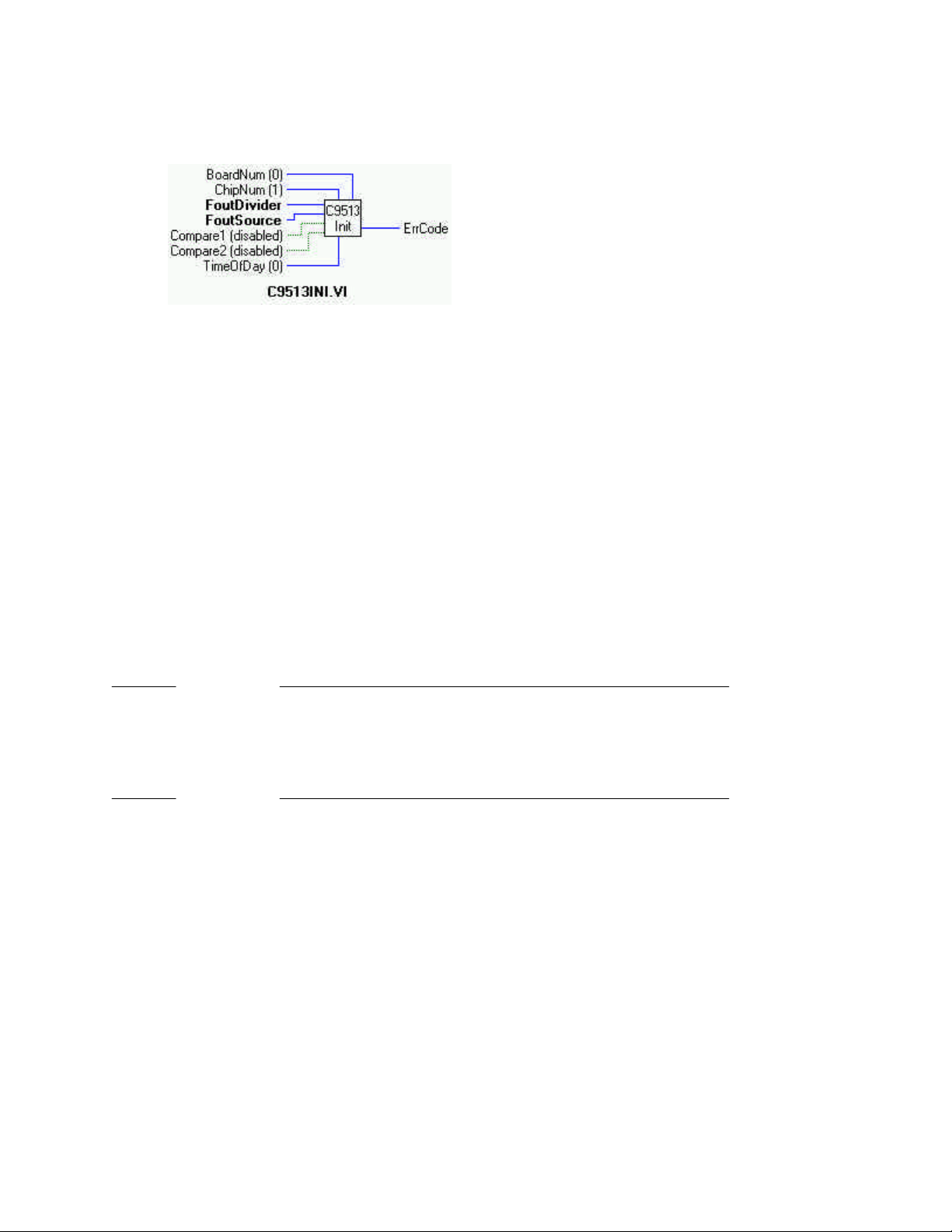
C9513Init.VI
Description:
Initializes all of the chip level features of a 9513 counter chip. This VI can only be used with 9513 counters.
Summary:
Inputs: BoardNum [U32] - The board number when installed with InstaCal. Can be 0 to 100.
ChipNum [U32] - Specifies which 9513 chip is to be initialized.
FoutDivider [U32] - F-Out divider (0-15)
FoutSource [U32] - Specifies source of the signal for F-Out signal.
Compare1 [TF] - ENABLED or DISABLED
Compare2 [TF]- ENABLED or DISABLED
TimeOfDay [U32] - DISABLED or 1-3
Output: ErrCode [U32]- Error code
Explanation of the Arguments:
BoardNum - refers to the board number associated with the board when it was installed with the configuration program. The specified board must have a 9513 counter.
ChipNum - Specifies which 9513 chip is to be initialized. For a CTR05 board this should be set to 1. For a CTR10 board it should be
either 1 or 2. For a CTR20 it should be 1 - 4.
FoutDivider -
VI Syntax Corresponds to 9513 description in Counter Mode Register Description
0 Divide by 16
1 Divide by 1
2 ... 15 Divide by the number 2 ... 15
FoutSource -
VI Syntax Corresponds to 9513 description in Counter Mode Register Description
TCPREVCTR TCN - 1 (Terminal count of previous counter)
CTRINPUT1 SRC 1 (Counter Input 1)
CTRINPUT2 SRC 2 (Counter Input 2)
CTRINPUT3 SRC 3 (Counter Input 3)
CTRINPUT4 SRC 4 (Counter Input 4)
CTRINPUT5 SRC 5 (Counter Input 5)
GATE1 GATE 1
GATE2 GATE 2
GATE3 GATE 3
GATE4 GATE 4
GATE5 GATE 5
FREQ1 F1
FREQ2 F2
FREQ3 F3
FREQ4 F4
FREQ5 F5
36
Page 41

Compare1 -
VI Syntax Corresponds to 9513 description in Counter Mode Register Description
DISABLED Disabled (False)
ENABLED Enabled
Compare2 VI Syntax Corresponds to 9513 description in Counter Mode Register Description
DISABLED Disabled (False)
ENABLED Enabled
TimeOf Day VI Syntax Corresponds to 9513 description in Counter Mode Register Description
0 TOD Disabled
1 TOD Enabled / 5 Input
2 TOD Enabled / 6 Input
3 TOD Enabled / 10 Input
No Arguments - For:
VI Set To Corresponds to 9513 description in Counter Mode Register Description
0 (FOUT on) FOUT Gate
0 (Data bus matches board) Data Bus Width
1 (Disable Increment) Data Pointer Control
1 (BCD Scaling) Scalar Control
37
Page 42
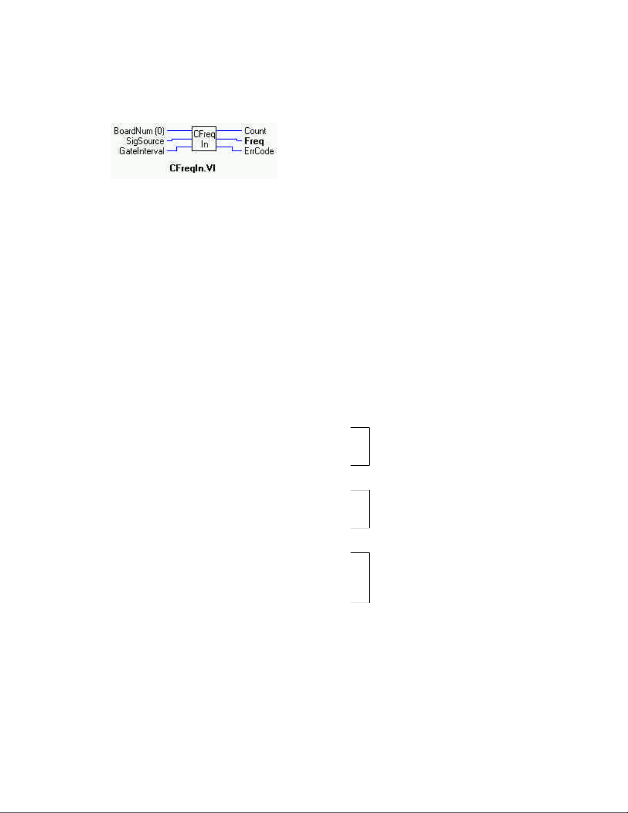
CFreqIn.VI
Description:
Measures the frequency of a signal. This VI can only be used with 9513 counters. This VI uses internal counters #5 and #4.
Summary:
Inputs: BoardNum [U32] - The board number when installed with InstaCal. Can be 0 to 100.
SigSource [U32]- specifies which signal will be measured
GateInterval [I16] - gating interval in milliseconds
Outputs: Count [U32] - The raw count is returned here
Freq [U32] - the measured frequency in Hz returned here.
ErrCode [I32] - Error code
Explanation of the Arguments:
BoardNum - refers to the board number associated with the board when it was installed with the configuration program. The specified board must have a 9513 counter.
SigSource - specifies the source of the signal from which the frequency will be calculated.
The signal to be measured is routed internally from the source specified by SigSource to the clock input of counter 5. On boards with
more than one 9513 chip, there is more than one counter 5. Which counter 5 is used is also determined by SigSource. SigSource can
be set to one of the following values:
One 9513 chip:
CTRINPUT1 through CTRINPUT5
Chip 1 usedGATE1 through GATE4
FREQ1 through FREQ5
Two 9513 chips:
CTRINPUT1 through CTRINPUT10
Chip 1 or Chip 2 usedGATE 1 through GATE 9 (excluding gate 5)
FREQ1 through FREQ10
Four 9513 chips:
CTRINPUT1 through CTRINPUT20
Chips 1- 4 can be usedGATE1 through GATE19 (excluding gates 5, 10 &
15)
FREQ1 through FREQ20
The SigSource value determines which chip is used. CTRINPUT6 through CTRINPUT10, FREQ6 through FREQ10 and GATE6
through GATE9 indicate chip 2 will be used. The signal to measure must be present at the chip 2 input specified by SigSource. Also,
the gating connection from counter 4 output to counter 5 gate must be made between counters 4 and 5 OF THIS CHIP (see below).
See board specific information to determine valid values for your board
GateInterval - specifies the time (in milliseconds) that the counter will be counting. The optimum GateInterval depends on the frequency of the measured signal. The counter can count up to 65535.
If the gating interval is too low, then the count will be too low and the resolution of the frequency measurement will be poor. For
example, if the count changes from 1 to 2 the measured frequency doubles.
38
Page 43

If the gating interval in too long then the counter will overflow and a FREQOVERRUN error will occur.
Note:
This function requires an electrical connection between counter 4 output and counter 5 gate. This connection must be made between
counters 4 and 5 ON THE CHIP DETERMINED BY SIGSOURCE.
Also, cb9513Init() must be called for each ChipNum that will be used by this function. The values of FoutDivider, FoutSource, Compare1, Compare2, and Time of Day are irrelevant to this function and can be any value shown in the cbC9513Init function description.
39
Page 44
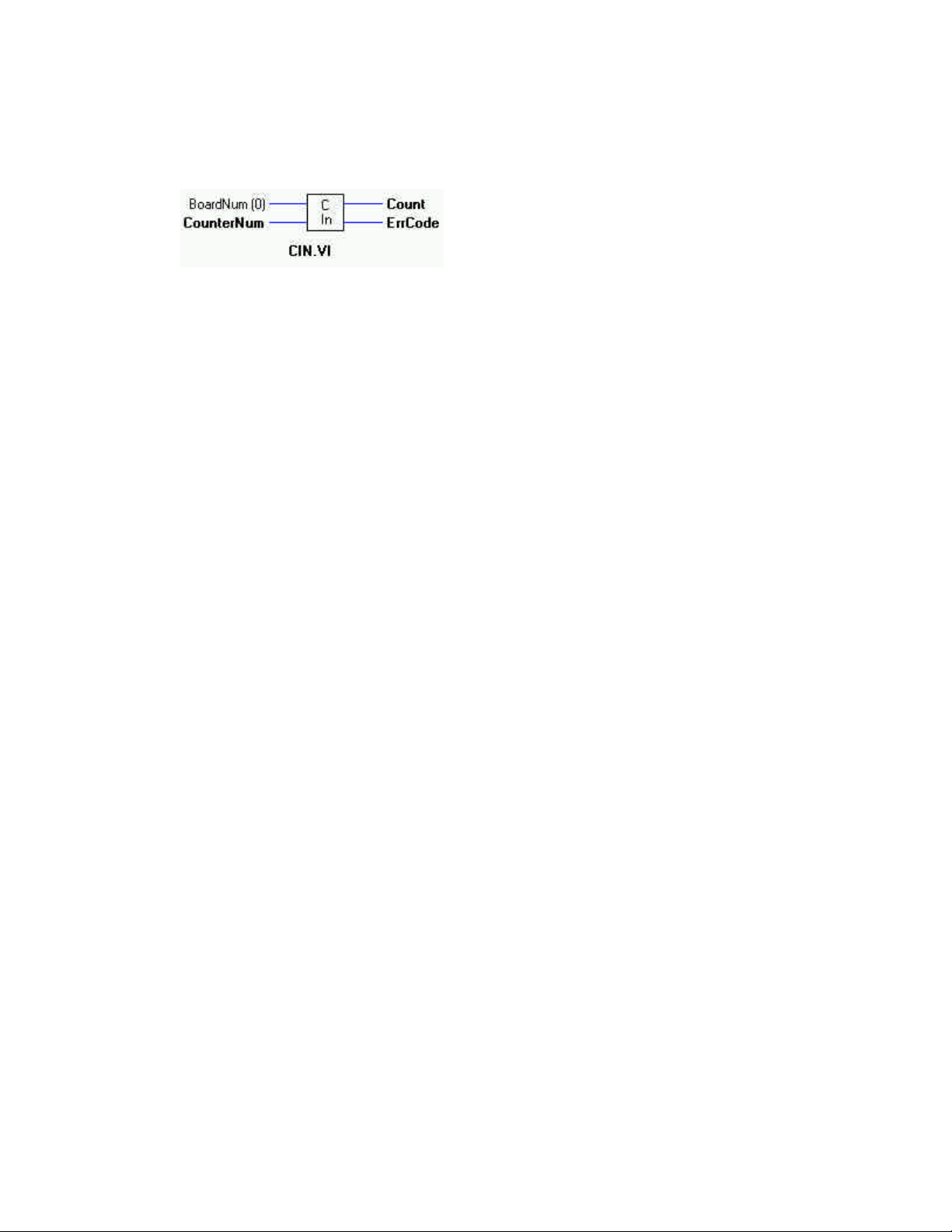
CIn.VI
Description:
Reads the current count from a counter
Summary:
Inputs: BoardNum [U32] - The board number when installed with InstaCal. Can be 0 to 100.
CounterNum [I32] - counter number to read
Outputs: Count [I32] - Count returned here
ErrCode [I32] - Error code
Explanation of the Arguments:
BoardNum - refers to the board number associated with the board when it was installed with the configuration program. The specified board must have a counter.
CounterNum - The counter to read current count from. Valid values are 1 to 20, up to the number of counters on the board.
1 Counter input to counter 1. CTR1
2 ...20 Counter inputs 2 through 20
40
Page 45

cbCIn32()
Description: Reads the current count from a counter and returns it as a 32-bit integer.
Summary: int cbCIn32 (int BoardNum, int CounterNum, unsigned long *Count)
Arguments: BoardNum [U32] - The board number when installed with InstaCal. Can be 0 to 100.
CounterNum [I32] - Counter number( 1 − n) to read
Count [I32] - Current count is returned here
ErrCode [I32] - Error code
Explanation of the Arguments:
BoardNum - Refers to the board number associated with the board when it was installed with the configuration program. The specified board must have an LS7266 counter.
CounterNum - The counter to read current count from. Valid values are 1 to N, where N is the number of counters on the board.
Count - Current count value from selected counter is returned here
Returns - Error code or 0 if no error occurs
Note: cbCIn() vs cbCIn32()
The cbCIn() and cbCIn32() perform the same operation. The only difference between the two is that cbCIn() returns a 16-bit count
value and cbCIn32() returns a 32 bit value. The only time you need to use cbCIn32() is when reading counters that are larger than 16
bits. The only boards that have such counters are the quadrature encoder input boards (CIO-QUAD02, CIO-QUAD04, PCMQUAD02). For these boards both cbCIn() and cbCIn32() can be used but cbCIn32 is required whenever you need to read count values greater than 16 bits (counts > 65535).
41
Page 46
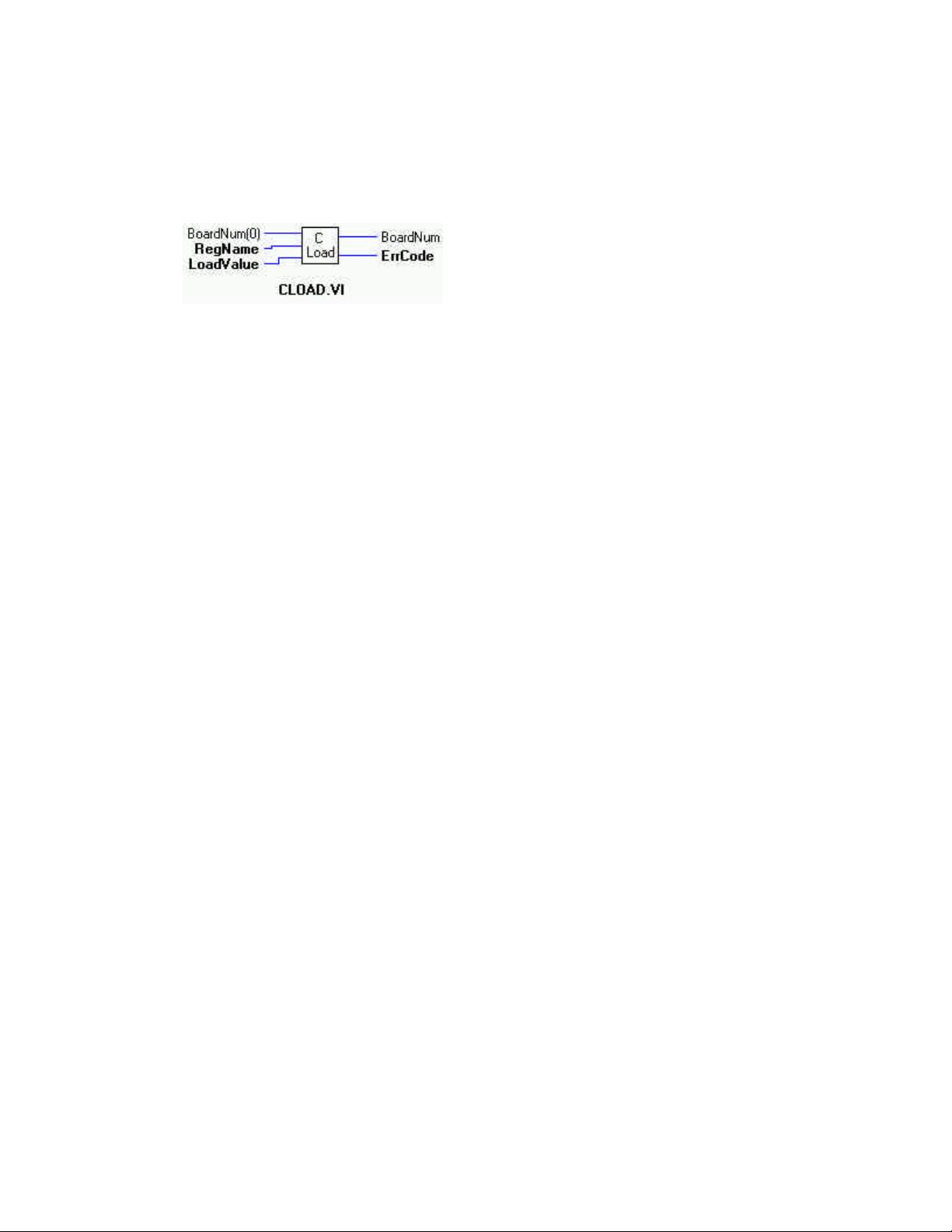
CLoad.VI
Description:
Loads the specified counter's LOAD, HOLD, COUNT, PRESET, or PRESCALER, ALARM register with a count. When you want to
load a counter with a value to count from, it is never loaded directly into the counter's count register. It is loaded into the load or
hold register. From there, the counter, after enabled, loads the count from the appropriate register, generally on the first valid pulse.
Summary:
Inputs: BoardNum [U32] - The board number when installed with InstaCal. Can be 0 to 100.
RegName [U32] - Register to loaded with LoadValue.
LoadValue [U16] - Value to be loaded into RegName register.
Outputs: BoardNum [U32] - The board number when installed with InstaCal. Can be 0 to 100.
ErrCode [U32]- Error code
Explanation of the Arguments:
BoardNum - refers to the board number associated with the board when it was installed with the configuration program. The specified board must have a counter.
RegName - The register to load the count to. Valid values are:
LOADREG1 .. 20 Load registers 1 through 20. This may span several chips.
HOLDREG1 .. 20 Hold registers 1 through 20. This may span several chips. (9513 only)
ALARM1CHIP1 Alarm register 1 of the first counter chip. (9513 only)
ALARM2CHIP1 Alarm register 2 of the first counter chip. (9513 only)
ALARM1CHIP2 Alarm register 1 of the second counter chip. (9513 only)
ALARM2CHIP2 Alarm register 2 of the second counter chip. (9513 only)
ALARM1CHIP3 Alarm register 1 of the third counter chip. (9513 only)
ALARM2CHIP3 Alarm register 2 of the third counter chip. (9513 only)
ALARM1CHIP4 Alarm register 1 of the four counter chip. (9513 only)
ALARM2CHIP4 Alarm register 2 of the four counter chip. (9513 only)
COUNT1...4 Current Count (LS7266 only)
PRESET1...4 Preset register (LS7266 only)
PRESCALER1...4 Prescaler register (LS7266 only)
LoadValue - The value to be loaded. Must be between 0 and 2 ^ resolution − 1 of the counter. For example, a 16-bit counter
is 2 ^ 16 − 1, or 65,535.
Counter Types: There are several counter types supported. Please refer to the data sheet for the registers available for a counter
type.
42
Page 47

cbCLoad32()
Description: Loads the specified counter’s COUNT, PRESET or PRESCALER register with a count.
Summary: int cbCLoad32 (int BoardNum, int RegName, unsigned long LoadValue)
Arguments:
Inputs: BoardNum [U32] - The board number when installed with InstaCal. Can be 0 to 100.
RegName [U32] - Register to load LoadValue in to.
LoadValue [U32] - Value to be loaded into RegName
Outputs: BoardNum [U32] - The board number when installed with InstaCal. Can be 0 to 100.
ErrCode [U32]- Error code
Explanation of the Arguments:
BoardNum - Refers to the board number associated with the board when it was installed with the configuration program. The specified board must have an LS7266 counter.
RegName - The register to load the value into. Valid register names are:
COUNT1 - 4 Used to initialize the counter
PRESET1 - 4 Used to set upper limit of counter in some modes
PRECSALER1 - 4 Used for clock filtering
LoadValue - The value to be loaded.
Returns - Error code or 0 if no error occurs
Note: cbCLoad() vs cbCLoad32()
The cbCLoad() and cbCLoad32() perform the same operation. The only difference between the two is that cbCLoad() loads a 16-bit
count value and cbCLoad32() loads a 32 bit value. The only time you need to use cbCLoad32() is when loading counts that are larger
than 32 bits (counts > 65535).
43
Page 48

cbCStatus()
Description: Returns status information about the specified counter (7266 counters only)
Summary: int cbCStatus (int BoardNum, int CounterNum, unsigned long *StatusBits)
Arguments: BoardNum [U32] - The board number when installed with InstaCal. Can be 0 to 100.
CounterNum [I32] - Counter number( 1 - n) to read
StatusBits [U32] - Status information is returned here
Explanation of the Arguments:
BoardNum - Refers to the board number associated with the board when it was installed with the configuration program. The specified board must have an LS7266 counter.
CounterNum - The counter to read current count from. Valid values are 1 to N, where N is the number of counters on the board.
StatusBits - Current status from selected counter is returned here. The status consists of individual bits that indicate various conditions within the counter. The currently defined status bits are:
C_UNDERFLOW - Is set to 1 whenever the count decrements past 0. Is cleared to 0 whenever cbCGetStatus() is called.
C_OVERFLOW - Is set to 1 whenever the count increments past it’s upper limit. Is cleared to 0 whenever cbCGetStatus() is
called.
C_COMPARE - Is set to 1 whenever the count matches the preset register. Is cleared to 0 whenever cbCGetStatus() is
called.
C_SIGN - Is set to 1 when the MSB of the count is 1. Is cleared to 0 whenever the MSB of the count is set to 0.
C_ERROR - Is set to 1 whenever an error occurs due to excessive noise on the input. Is cleared to 0 by calling cbC7266Con-
fig().
C_UP_DOWN - Is set to 1 when counting up. Is cleared to 0 when counting down
C_INDEX - Is set to 1 when index is valid. Is cleared to 0 when index is not valid.
Returns - Error code or 0 if no error occurs
44
Page 49
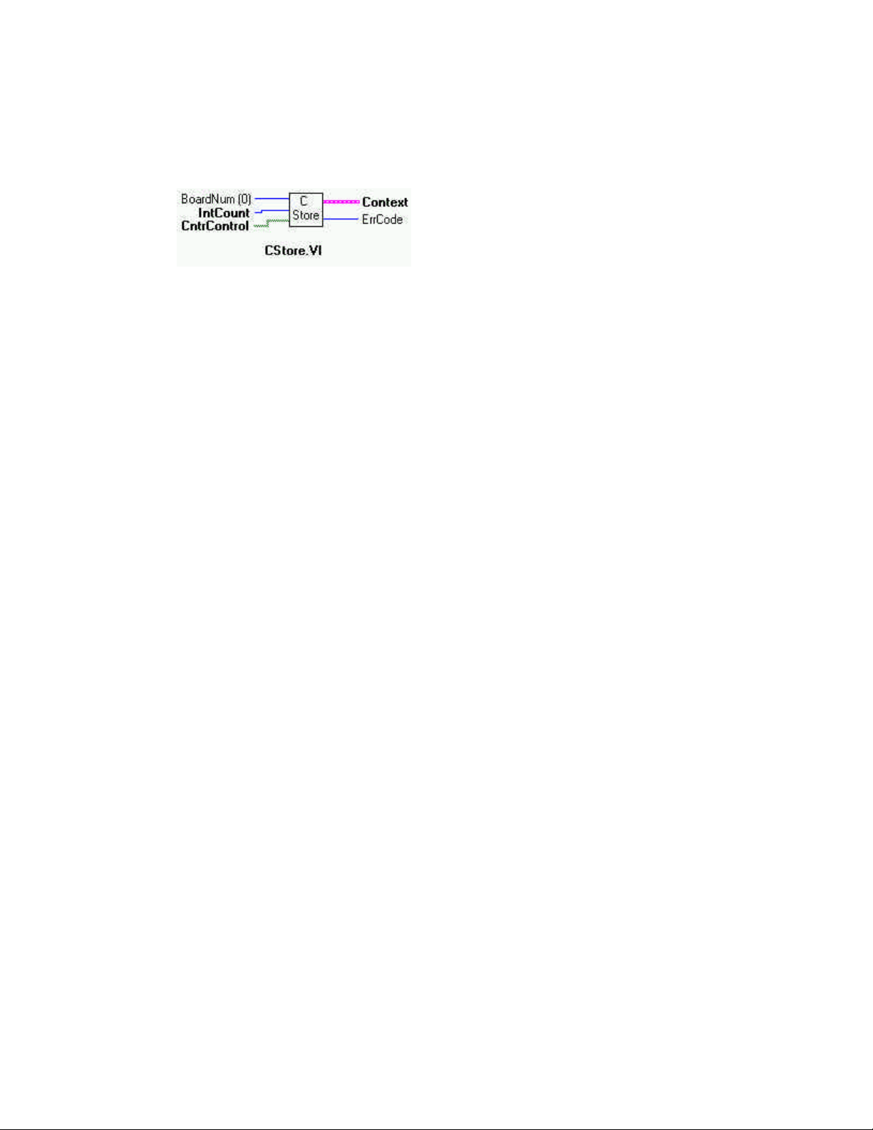
CStore.VI Changed R4.0 RW (MOD)
Description:
Installs an interrupt handler that will store the current count whenever an interrupt occurs. This VI can only be used with 9513
counters. This VI will continue to operate in the background until either IntCount has been satisfied or StopBg.VI is called.
Summary:
Inputs: BoardNum [U32] - The board number when installed with InstaCal. Can be 0 to 100.
IntCount [I16] - Number of interrupts
CntrControl [TF] - Array with each element set to either ENABLED or DISABLED
Outputs: Context [cluster] - Output data structure
ErrCode [I32] -Error code
Explanation of the Arguments:
BoardNum - refers to the board number associated with the board when it was installed with the configuration program. The specified board must have a 9513 counter.
IntCount - The counters will be read every time an interrupt occurs until IntCount interrupts have occurred. If IntCount is = 0 then
the VI will run until StopBg.VI is called.
CntrControl - The array should have an element for each counter on the board. (5 elements for CTR-05 board, 10 elements for a
CTR-10, etc.). Each element corresponds to a possible counter channel. Each element should be set to either DISABLED (F) or
ENABLED (True). All channels that are set to ENABLED will be read when an interrupt occurs.
Context - Data structure containing information from a background operation. Some of the information included is the board
number, the data array, the array size, and the initial status of the background operation.
NOTE:
Wiring of this VI should conform to the following pattern:
Start CStore.VI. GetStat.VI checks for completion (boolean output called "Running"). StopBg.VI terminates the operation,
if not already done, and frees memory aliases. Data output from the background operation is passed to GetStat.VI and StopBg.VI via
"Context", and can be wired from one or both of them for intermediate or final actions, respectively. The demo VIs illustrate this
process effectively.
New Functionality: If the Library Revision is set to 4.0 or greater then the following code changes are required.
If IntCount is non-zero then the Context object will contain IntCount samples for each counter. Counter elements that are DISABLED will return 0.
For example, if IntCount is set to 100 for a CTR-05 board, then the new functionality keeps the user application from having to
move the data out of the context buffer for every interrupt, before it is overwritten. Now, for each interrupt the counter values will be
stored in adjacent memory locations within the context.
Note: Specifying IntCount to be a non-zero value and failing to allocate the proper sized array will result in a runtime error. There
is no way for the Universal Library to determine if the array has been allocated with the proper size.
If IntCount = 0 the functionality is unchanged.
45
Page 50
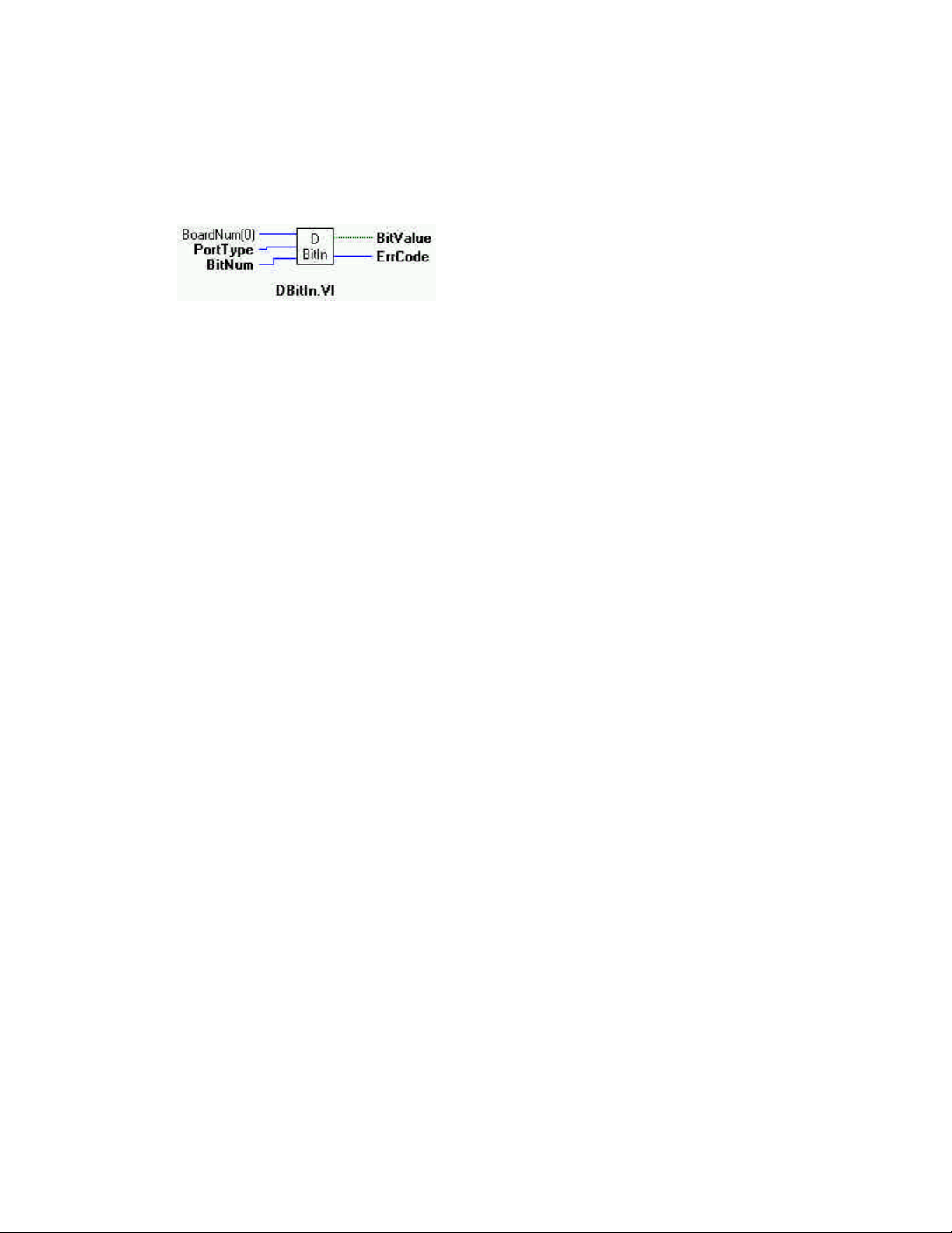
DBitIn.VI
Description:
Reads the state of a single digital input bit. This VI treats all of the DI/O ports on a board as a single very large port. It lets you read
the state of any individual bit within this large port. If the port type is not AUXPORT, you must use DCfgPrt.VI to configure the port
for input first.
Summary:
Inputs: BoardNum [U32] - The board number when installed with InstaCal. Can be 0 to 100.
PortType [I32] - Specifies which type of digital port to read
BitNum [I32] - Specifies which bit to read BitValue
Outputs: BitValue [TF] - Place holder for return value of bit - the bit's value (0 or 1) is returned here
ErrCode [I32] - Error code
Explanation of the Arguments:
BoardNum - refers to the board number associated with the board when it was installed with the configuration program.
PortType- There are two general types of digital I/O - 8255 and other. Some boards (DIO Series) use an 8255 for digital I/O. For
these boards PortType should be set to FIRSTPORTA. Other boards don't use 8255. For these boards PortType should be set to
AUXPORT. Some boards have both types of digital I/O (DAS1600). Set PortNum to either FIRSTPORTA or AUXPORT depending
on which digital inputs you wish to read.
BitNum - This specifies the bit number within the single large port. The specified bit must be in a port that is currently configured as
an input.
The tables below show which bit numbers are in which 82C55 and 8536 digital chips. The most 82C55 chips on a single board is
eight (8), on the CIO-DIO196. The most (2) 8536 chips occur on the CIO-INT32.
82C55 Bit# Chip # Address 8536 Bit# Chip # Address
0 - 23 1 Base + 0 0 - 19 1 Base + 0
24 - 47 2 Base + 4 20 - 39 2 Base + 4
48 - 71 3 Base + 8
72 - 96 4 Base + 12
96 - 119 5 Base + 16
120 - 143 6 Base + 20
144 - 167 7 Base + 24
168 - 191 8 Base + 28
BitValue - Place holder for return value of bit. Value will be 0 or 1. A 0 indicates a low reading, a 1 indicates a logic high reading.
Logic high does not necessarily mean 5V. See the board manual for chip input specifications.
46
Page 51
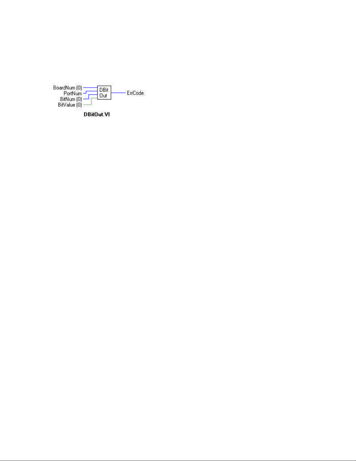
DBitOut.VI
Description:
Sets the state of a single digital output bit. This VI treats all of the DIO chips on a board as a single very large port. It lets you set the
state of any individual bit within this large port. If the port type is not AUXPORT you must use DCfgprt.VI to configure the port for
output first.
Summary:
Inputs: BoardNum [U32] - The board number when installed with InstaCal. Can be 0 to 100.
PortNum [U32] - Specifies which digital port (AUXPORT, FIRSTPORTA).
BitNum [U32] - specifies which bit to write
BitValue [TF] - the bit's value (0 or 1)
Output: ErrCode - Error code
Explanation of the Arguments:
BoardNum - refers to the board number associated with the board when it was installed with the configuration program.
PortType - There are two general types of digital I/O - 8255 and other. Some boards (DIO Series) use an 8255 for digital I/O. For
these boards PortType should be set to FIRSTPORTA. Other boards don't use 8255. For these boards PortType should be set to
AUXPORT. Some boards have both types of digital I/O (CIO-DAS1600). Set PortNum to either FIRSTPORTA or AUXPORT
depending on which digital inputs you wish to write.
BitNum - This specifies the bit number within the single large port. The specified bit must be in a port that is currently configured as
an output.
The tables below show which bit numbers are in which 82C55 and 8536 digital chips. The most 82C55 chips on a single board is
eight (8), on the CIO-DIO196. The most (2) 8536 chips occur on the CIO-INT32.
82C55 Bit# Chip # Address 8536 Bit# Chip # Address
0 - 23 1 Base + 0 0 - 19 1 Base + 0
24 - 47 2 Base + 4 20 - 39 2 Base + 4
48 - 71 3 Base + 8
72 - 96 4 Base + 12
96 - 119 5 Base + 16
120 - 143 6 Base + 20
144 - 167 7 Base + 24
168 - 191 8 Base + 28
BitValue - The output value of the bit. Value will be 0 or 1. A (0) indicates a logic-low output; a (1) indicates a logic high output.
Logic-high does not necessarily mean 5V. See the board manual for chip specifications.
47
Page 52
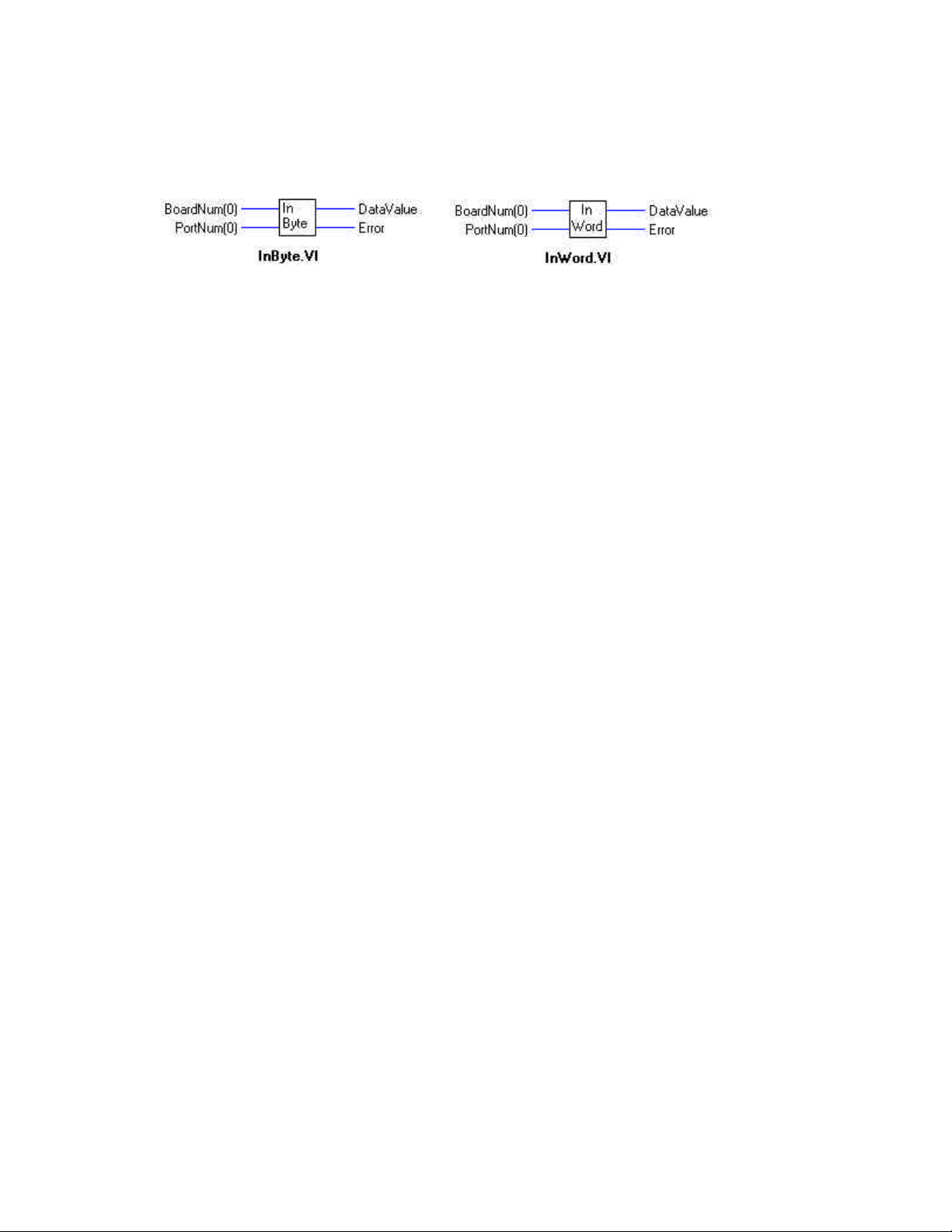
InByte.VI/ InWord.VI
Description:
Reads a byte or a word from a hardware register on a board.
Summary:
Inputs: BoardNum [U32] - The board number when installed with InstaCal. Can be 0 to 100.
PortNum [U32] - register on the board to read
Outputs: DataValue [I32] - Value read from port
ErrCode [I32] - Error Code
Explanation of the Arguments:
BoardNum - refers to the number associated with the board when it was installed with the configuration program.
PortNum - register within the board. Boards are set to a particular base address. The registers on the boards are at addresses that are
offsets from the base address of the board (BaseAdr+0, BaseAdr+2, etc.). This argument should be set to the offset for the desired
register. This function takes care of adding the base address to the offset so that the board's address can be changed without changing
the code.
NOTES:
InByte.VI is used to read 8-bit ports. InWord.VI is used to read 16-bit ports.
Returns: The current value of the specified register
48
Page 53
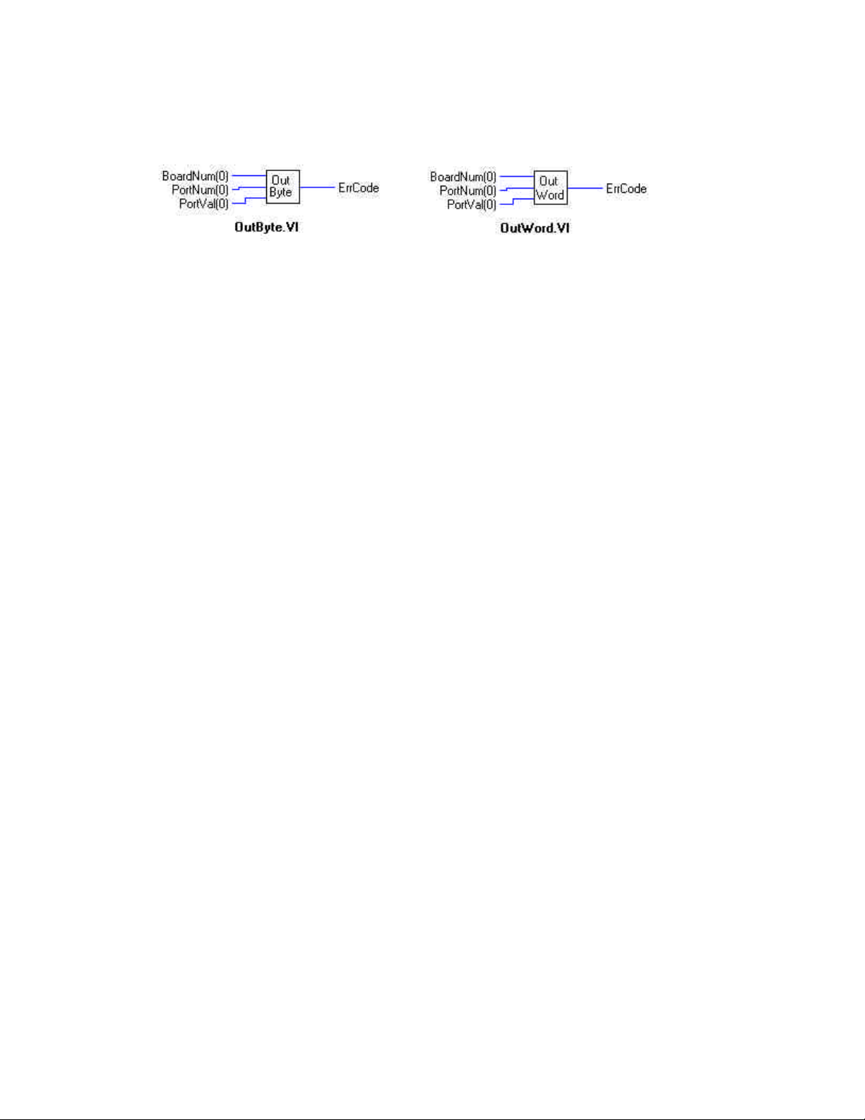
OutByte.VI / OutWord.VI
Description:
Writes a byte or a word to a hardware register on a board.
Summary:
Inputs: BoardNum [U32] - The board number when installed with InstaCal. Can be 0 to 100.
PortNum [U32] - register on the board to write to
PortVal [U32] - value to write to register
Outputs: ErrCode [I32] - Error Code
Explanation of the Arguments:
BoardNum - refers to the board number associated with the board when it was installed with the configuration program.
PortNum - register within the board. Boards are set to a particular base address. The registers on the boards are at addresses that are
offsets from the base address of the board (BaseAdr+0, BaseAdr+2, etc). This argument should be set to the offset for the desired
register. This function takes care of adding the base address to the offset, so that the board's address can be changed without changing the code.
PortVal - Value that will be written to the register
NOTES:
OutByte.VI is used to write to 8-bit ports. OutWord.VI is used to write to 16-bit ports.
49
Page 54
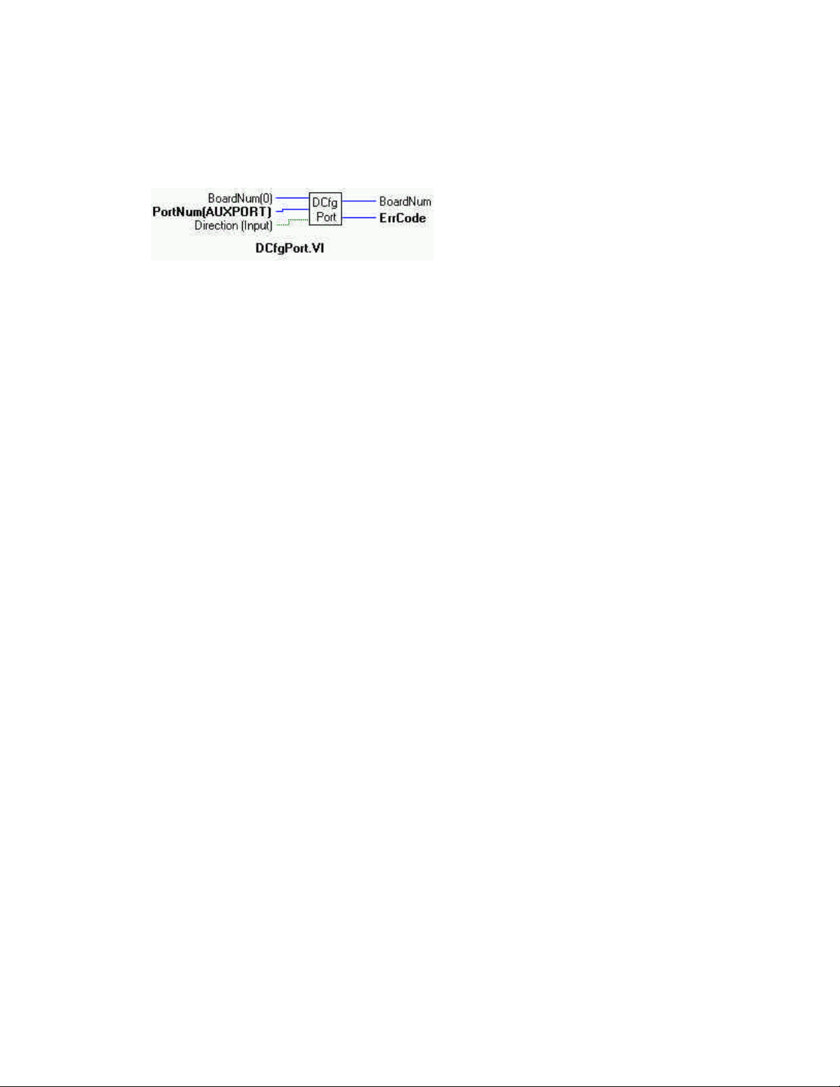
DCfgPort.VI
Description:
Configures a digital port as Input or Output. This mode is for use with 82C55 chips and 8536 chips. See the board user's manual for
details of chip operation.
Summary:
Inputs: BoardNum [U32] - The board number when installed with InstaCal. Can be 0 to 100.
PortNum [I32] - Specifies which digital I/O port to configure.
Direction [TF]- DIGITALOUT or DIGITALIN
Outputs: BoardNum [U32] - Board number
ErrCode [I32]- Error code
Explanation of the Arguments:
BoardNum - refers to the board number associated with the board when it was installed with the configuration program.
PortNum - The specified port must be configurable. The AUXPORT is not configurable. It is always configured for inputs and outputs.
The tables below show which ports and bit numbers are in which 82C55 and 8536 digital chips. The most 82C55 chips on a single
board is eight (8), on the CIO-DIO196. The most (2) 8536 chips occur on the CIO-INT32.
Mnemonic Bit# 8255 Chip # Chip Address 8536 Chip # Chip Address
FIRSTPORTA 0 - 7 1A Base + 0 1A Base + 0
FIRSTPORTB 8 - 15 1B 1B
FIRSTPORTCL 16 - 19 1CL 1C
FIRSTPORTCH 20 - 23 1CH Not present
SECONDPORTA 24 - 31 2A Base + 4 2A Base + 4
SECONDPORTB 32 - 39 2B 2B
SECONDPORTCL 40 - 43 2CL 2C
SECONDPORTCH 44 - 47 2CH No port C High in 8536 chips
and so on to the last chip on the board as: THIRDPORT@, FOURTHPORT@, FIFTHPORT@, SIXTHPORT@,
SEVENTHPORT@ and
EIGHTHPORTA 168 - 175 8A Base + 28
EIGHTHPORTB 176 - 183 8B
EIGHTHPORTCL 184 - 187 8CL
EIGHTHPORTCH 188 - 191 8CH
Direction - DIGITALOUT (T) or DIGITALIN (default) configures an entire eight- or four-bit port for output or input.
Returns: Error code or 0 if no errors
Note: Using this function will reset all ports on a chip configured for output to a zero state. This means that if you set an output
value on FIRSTPORTA and then change the configuration on FIRSTPORTB from OUTPUT to INPUT, the output value at
FIRSTPORTA will be all zeros. You can, however, set the configuration on SECONDPORTX without affecting the value at
FIRSTPORTA. For this reason, this function is usually called at the beginning of the program for each port requiring configuration.
50
Page 55
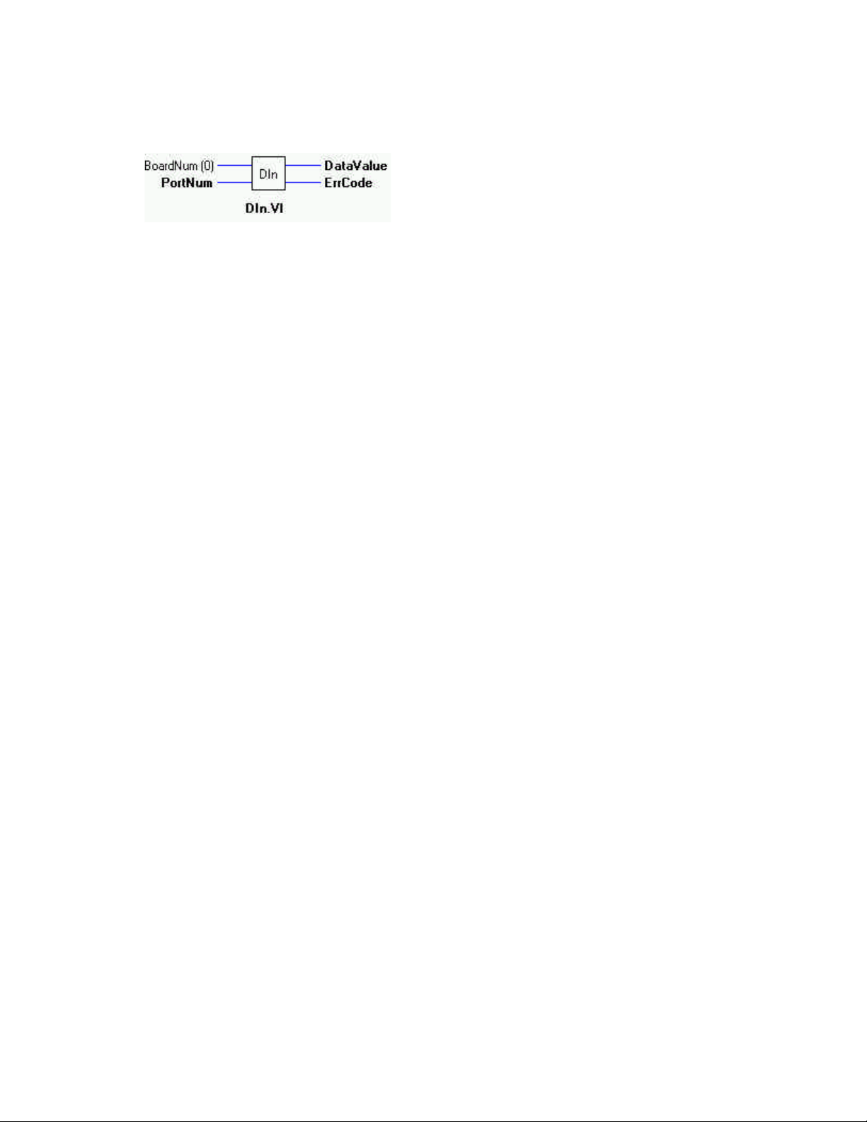
DIn.VI
Description:
Reads a digital input port
Summary:
Inputs: BoardNum [U32] - The board number when installed with InstaCal. Can be 0 to 100..
PortNum [I32] - Specifies which digital I/O port to read.
Outputs: DataValue [I16] - Digital input value.
ErrCode [I32] - Error code
Explanation of the Arguments:
BoardNum - refers to the board number associated with the board when it was installed with the configuration program.
PortNum - If the port type is not AUXPORT, the specified port must be configured for input. The AUXPORT is not configurable.
The tables below show which ports are in which 82C55 and 8536 digital chips. The most 82C55 chips on a single board is eight (8),
on the CIO-DIO196. The most (2) 8536 chips occur on the CIO-INT32.
Mnemonic 8255 Chip # Chip Address 8536 Chip # Chip Address
FIRSTPORTA 1A Base + 0 1A Base + 0
FIRSTPORTB 1B 1B
FIRSTPORTCL 1CL 1C
FIRSTPORTCH 1CH Not present
SECONDPORTA 2A Base + 4 2A Base + 4
SECONDPORTB 2B 2B
SECONDPORTCL 2CL 2C
SECONDPORTCH 2CH No port C High in 8536 chips
and so on to the last chip on the board as: THIRDPORT@, FOURTHPORT@, FIFTHPORT@, SIXTHPORT@,
SEVENTHPORT@ and
EIGHTHPORTA 8A Base + 28
EIGHTHPORTB 8B
EIGHTHPORTCL 8CL
EIGHTHPORTCH 8CH
The size of the ports vary. If it is an eight-bit port, the returned value will be in the range 0 to 255. If it is a four-bit port, the value
will be in the range 0 to 15.
IMPORTANT NOTE: Be sure to look at the example programs and the board specific information contained in the Universal
Library User's Guide for clarification of valid PortNum values.
51
Page 56
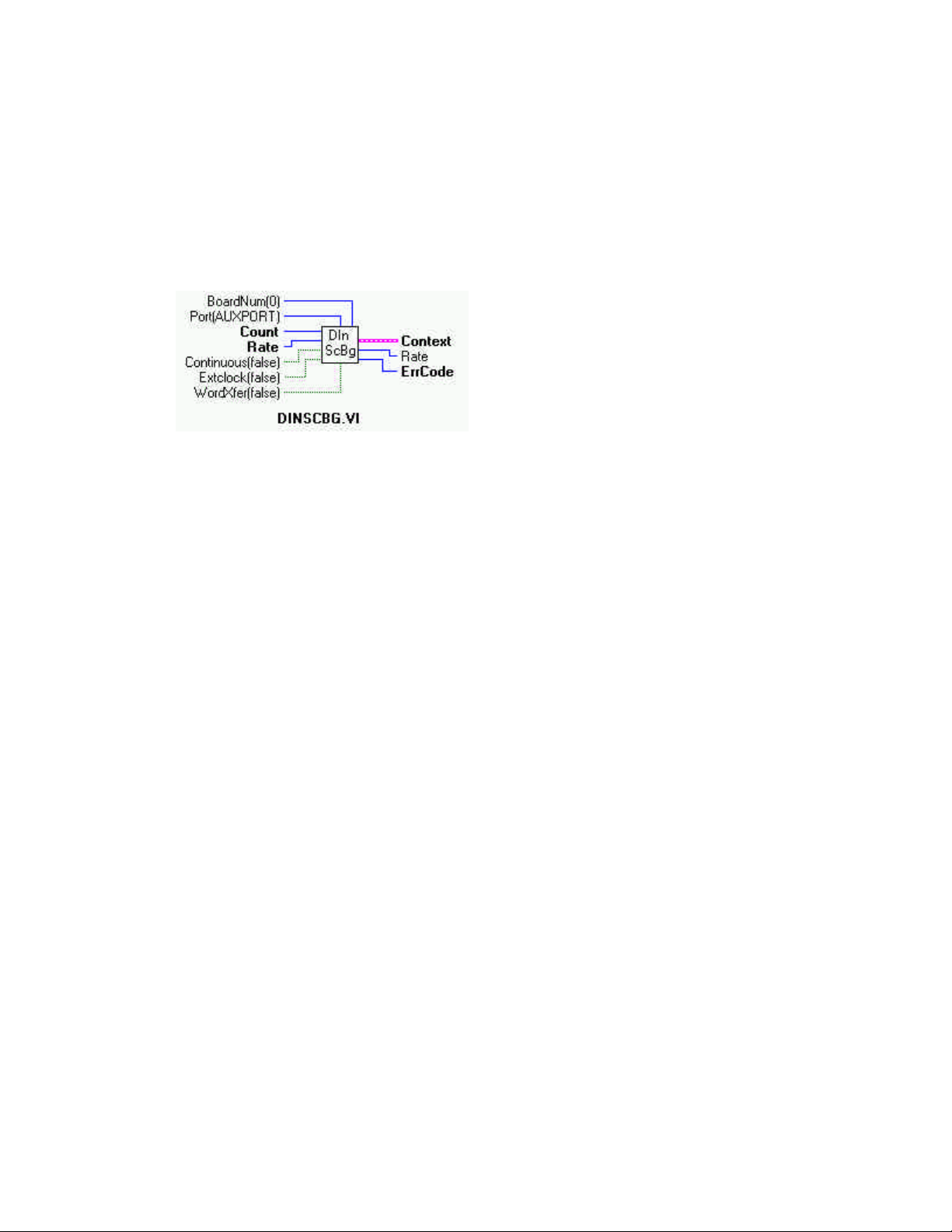
DInScBg.VI
Description:
Multiple reads of digital input port of a high speed digital port on a board with a pacer clock such as the CIO-PDMA16.
When this VI is used, control will return immediately to the next point in your program and the transfer from the digital input port
to the array in the Context will continue in the background. Use GetStat.VI to check on the status of the background operation. Use
StopBg.VI to terminate the background process before it has completed. StopBg should be used after any background operation to
clear variables and flags.
Summary:
Inputs: BoardNum [U32] - The board number when installed with InstaCal. Can be 0 to 100.
Port [I32] - Specifies which digital I/O port to read
Count [I32] - number of times to read digital input
Rate [I32] - Number of times per second (Hz) to read
Continuous [TF] - Continuous or single
Extclock [TF] - External or internal clock
WordXfer [TF] - Word or Byte transfer
Outputs: Context [cluster] - Output data structure *NOTE
Rate [I32]- Actual rate returned here
ErrCode [I32] - Error code
Explanation of the Arguments:
BoardNum - refers to the board number associated with the board when it was installed with the configuration program.
Port - Specifies which digital I/O port to read (usually FIRSTPORTA or FIRSTPORTB). The specified port must be configured as an
input.
Count - The number of times to read digital input
Rate - Number of times per second (Hz) to read the port. The actual sampling rate in some cases will vary a small amount from the
requested rate. The actual rate will be returned to the Rate argument.
Continuous - This option ( if True) puts the VI in an endless loop. After it transfers the required number of bytes it resets to the start
of the input array and begins again. The only way to stop this operation is with StopBg.VI. (A single execution is False).
ExtClock - If this option is used (True) then transfers will be controlled by the signal on the trigger input line rather than by the
internal pacer clock. Each transfer will be triggered on the appropriate edge of the trigger input signal (see board specific info).
When this option is used, the Rate argument is ignored. The transfer rate is dependent on the trigger signal. The default is TIMED
(F).
WordXfer - Normally (default is False) this VI reads a single (byte) port (BYTEXFER). If WORDXFER is specified, it will read two
adjacent ports on each read and store the value of both ports together as the low and high byte of a single array element in the input
array.
52
Page 57

Context - Data structure containing information from a background operation. Some of the information included is the board
number, the data array, the array size, and the initial status of the background operation.
NOTE:
Wiring of this VI should conform to the following pattern:
Ÿ DInScBg.VI starts a background operation.
Ÿ GetStat.VI checks for completion (boolean output called "Running").
Ÿ StopBg.VI terminates the operation, if not already done, and frees memory aliases.
Ÿ Data output from the background operation is passed to GetStat.VI and StopBg.VI via "Context". The data can be
wired from one or both of them for intermediate or final actions, respectively.
Ÿ The demo VIs illustrate this process effectively.
53
Page 58
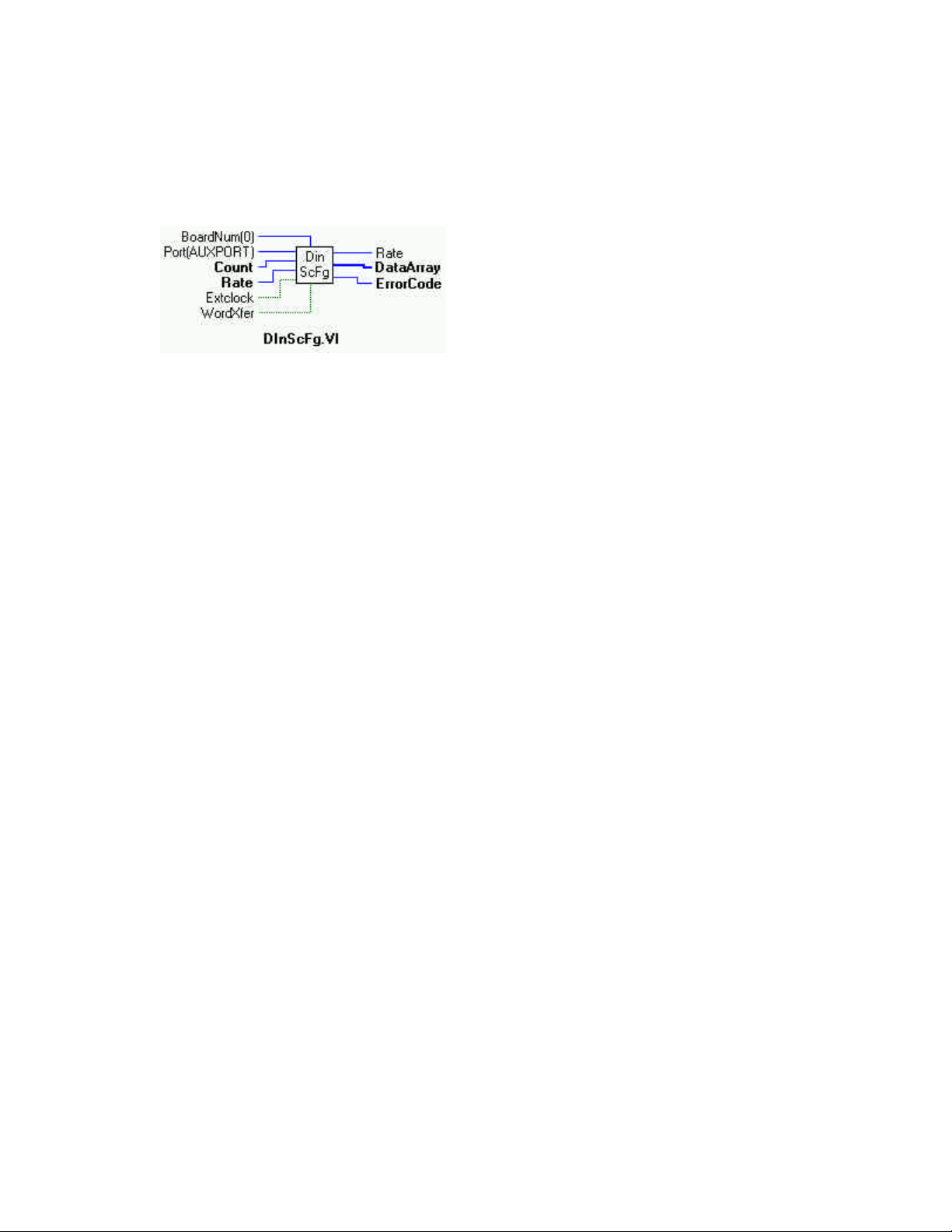
DInScFg.VI
Description:
Multiple reads of digital input port of a high speed digital port on a board with a pacer clock such as the CIO-PDMA16. As of this
revision of the manual and software, that is the CIO-PDMA16 only. The cDInScFg VI will not return to your program until all of
the requested data has been collected and returned to input array.
Summary:
Inputs: BoardNum [U32] - The board number when installed with InstaCal. Can be 0 to 100.
Port [I32] - Specifies which digital I/O port to read
Count [I32] - number of times to read digital input
Rate [I32]- Number of times per second (Hz) to read
Extclock [TF] - External or internal clock
WordXfer [TF] - Word or Byte transfer
Outputs: Rate [I32] - Actual rate returned here
DataArray [I16] - Data from scan is returned here
ErrCode [I32] - Error code
Explanation of the Arguments:
BoardNum - refers to the board number associated with the board when it was installed with the configuration program.
PortNum - Specifies which digital I/O port to read (usually FIRSTPORTA or FIRSTPORTB). The specified port must be configured
as an input.
Count - The number of times to read digital input
Rate - Number of times per second (Hz) to read the port. The actual sampling rate in some cases will vary a small amount from the
requested rate. The actual rate will be returned to the Rate argument.
EXTCLOCK - If this option (True) is used then transfers will be controlled by the signal on the trigger input line rather than by the
internal pacer clock. Each transfer will be triggered on the appropriate edge of the trigger input signal (see board-specific info).
When this option is used the Rate argument is ignored. The transfer rate is dependent on the trigger signal. The default is TIMED
(F).
WORDXFER - Normally this VI reads a single (byte) port (default, False). If WORDXFER is specified (True), it will read two adjacent ports on each read and store the value of both ports together as the low and high byte of a single array element in DataArray[].
DataArray - Data from the scan is returned here.
54
Page 59
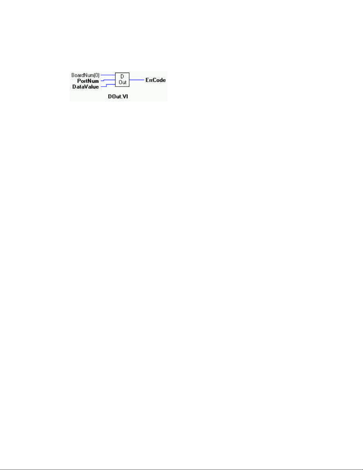
DOut.VI
Description:
Writes a byte to a digital output port .
Summary:
Inputs: BoardNum [U32] - The board number when installed with InstaCal. Can be 0 to 100.
PortNum [I32] - Specifies which digital I/O port to read.
DataValue [I32] - Digital output value input here.
Output: ErrCode [I32] - Error code
Explanation of the Arguments:
BoardNum - refers to the board number associated with the board when it was installed with the configuration program.
PortNum - If the port type is not AUXPORT, the specified port must be configured for output. The AUXPORT is not configurable.
The tables below show which ports are in which 82C55 and 8536 digital chips. The most 82C55 chips on a single board is eight (8),
on the CIO-DIO196. The most (2) 8536 chips occur on the CIO-INT32.
Mnemonic 8255 Chip # Chip Address 8536 Chip # Chip Address
FIRSTPORTA 1A Base + 0 1A Base + 0
FIRSTPORTB 1B 1B
FIRSTPORTCL 1CL 1C
FIRSTPORTCH 1CH Not present
SECONDPORTA 2A Base + 4 2A Base + 4
SECONDPORTB 2B 2B 2B
SECONDPORTCL 2CL 2C
SECONDPORTCH 2CH No port C High in 8536 chips
and so on to the last chip on the board as: THIRDPORT@, FOURTHPORT@, FIFTHPORT@, SIXTHPORT@,
SEVENTHPORT@ and
EIGHTHPORTA 8A Base + 28
EIGHTHPORTB 8B
EIGHTHPORTCL 8CL
EIGHTHPORTCH 8CH
Data Value - Value to write to the specified port.
The size of the ports varies. If it is an eight bit port then the output value must be in the range 0 to 255. If it is a four-bit port, the
value must be in the range 0 to 15.
IMPORTANT NOTE: Be sure to look at the example programs and the board specific information in the Universal Library User's
Guide for clarification of valid PortNum values.
55
Page 60
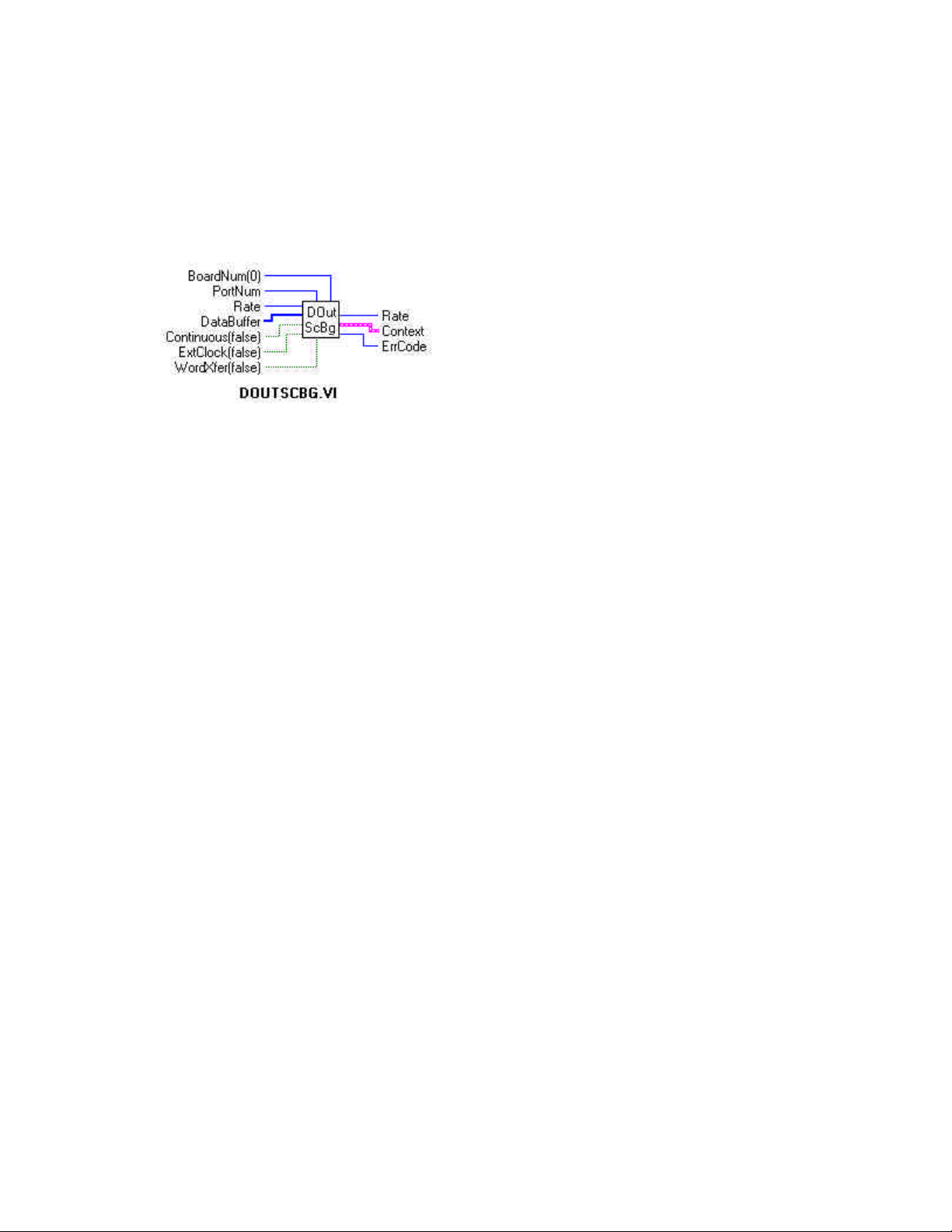
DOutScBg.VI
Description:
Multiple writes to digital output port of a high speed digital port on a board with a pacer clock. As of this revision of the manual and
software, that is the CIO-PDMA16 only. When this VI used, control will return immediately to the next point in your program and
the transfer to the digital output port from DataBuffer will continue in the background. Use GetStat.VI to check on the status of the
background operation. Use StopBg.VI to terminate the background process before it has completed. Always use the SpBg.VI after all
background operations to clear variables and flags.
Summary:
Inputs: BoardNum [U32] - The board number when installed with InstaCal. Can be 0 to 100.
PortNum [I32] - Specifies which digital I/O port to write
Rate [U32] - Number of times per second (Hz) to write
DataBuffer [I16] - Digital output values.
Extclock [TF] - External (T) or internal clock (F)
WordXfer [TF] - Word (T) or byte transfer (F)
Continuous [TF] - Run the VI in an endless loop (T)
Outputs: Rate [I32] - Actual scan rate
ErrCode [I32] - Error code
Context - [cluster]
Explanation of the Arguments:
BoardNum - refers to the board number associated with the board when it was installed with the configuration program.
PortNum - Specifies which digital I/O port to read. The two choices are FIRSTPORTA or FIRSTPORTB. The specified port must be
configured as an output.
Rate - Number of times per second (Hz) to write to the port. The actual update rate in some cases will vary a small amount from the
requested rate. The actual rate will be returned to the Rate argument.
DataBuffer - Data to the scan is input here.
Continuous - This option puts the VI in an endless loop. After it transfers the required number of bytes it resets to the start of
DataBuffer and begins again. The only way to stop this operation is with StopBg.VI.
ExtClock - If this option is used then transfers will be controlled by the signal on the trigger input line rather than by the internal
pacer clock. Each transfer will be triggered on the appropriate edge of the trigger input signal (see board specific info). When this
option is used the Rate argument is ignored. The transfer rate is dependent on the trigger signal.
WordXfer - Normally this VI reads a single (byte) port. If WORDXFER is specified then it will write two adjacent ports as the low
and high byte of a single array element in DataBuffer[].
Context - Data structure containing information from a background operation. Some of the information included is the board
number, the data array, the array size, and the initial status of the background operation.
56
Page 61

NOTE:
Wiring of this VI should conform to the following pattern:
DOutScBg.VI starts a background operation. GetStat.VI checks for completion (boolean output called "Running").
StopBg.VI terminates the operation, if not already done, and frees memory aliases. Data output from the background operation is
passed to GetStat.VI and StopBg.VI via "Context", and can be wired from one or both of them for intermediate or final actions,
respectively. The demo VIs illustrate this process effectively.
57
Page 62
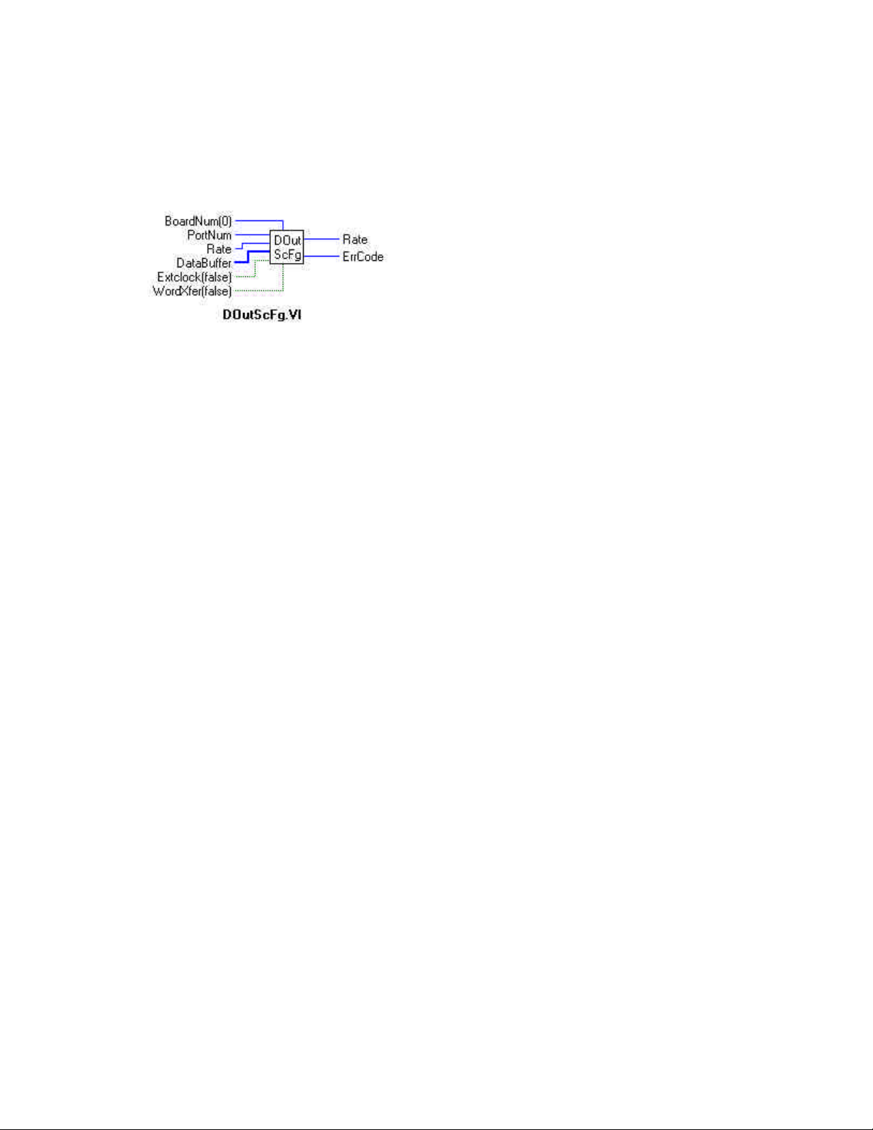
DOutScFg.VI
Description:
Multiple writes to digital output port of a high speed digital port on a board with a pacer clock. As of this revision of the manual and
software, that is the CIO-PDMA16 only. The DOutScFg.VI will not return to your program until all of the requested data has been
output.
Summary:
Inputs: BoardNum [U32] - The board number when installed with InstaCal. Can be 0 to 100.
PortNum [I32] - Specifies which digital I/O port to write
Rate [U32] - Number of times per second (Hz) to write
DataBuffer [I16] - Digital output values
Extclock [TF] - External (T) or internal clock (F)
WordXfer [TF] - Word (T) or byte transfer (F)
Outputs: Rate [I32] - Actual rate is returned here
ErrCode [I32] - Error code
Explanation of the Arguments:
BoardNum - refers to the board number associated with the board when it was installed with the configuration program.
PortNum - Specifies which digital I/O port to read. The two choices are FIRSTPORTA or FIRSTPORTB. The specified port must be
configured as an output.
Rate - Number of times per second (Hz) to write to the port. The actual update rate in some cases will vary a small amount from the
requested rate. The actual rate will be returned to the Rate argument.
DataBuffer - Data to the scan is input here
ExtClock - If this option is used then transfers will be controlled by the signal on the trigger input line rather than by the internal
pacer clock. Each transfer will be triggered on the appropriate edge of the trigger input signal (see board specific info). When this
option is used the Rate argument is ignored. The transfer rate is dependent on the trigger signal.
WordXfer - Normally this VI reads a single (byte) port. If WORDXFER is specified then it will write two adjacent ports as the low
and high byte of a single array element in DataBuffer[].
Transfer Method - Can not be specified. DMA is used.
58
Page 63
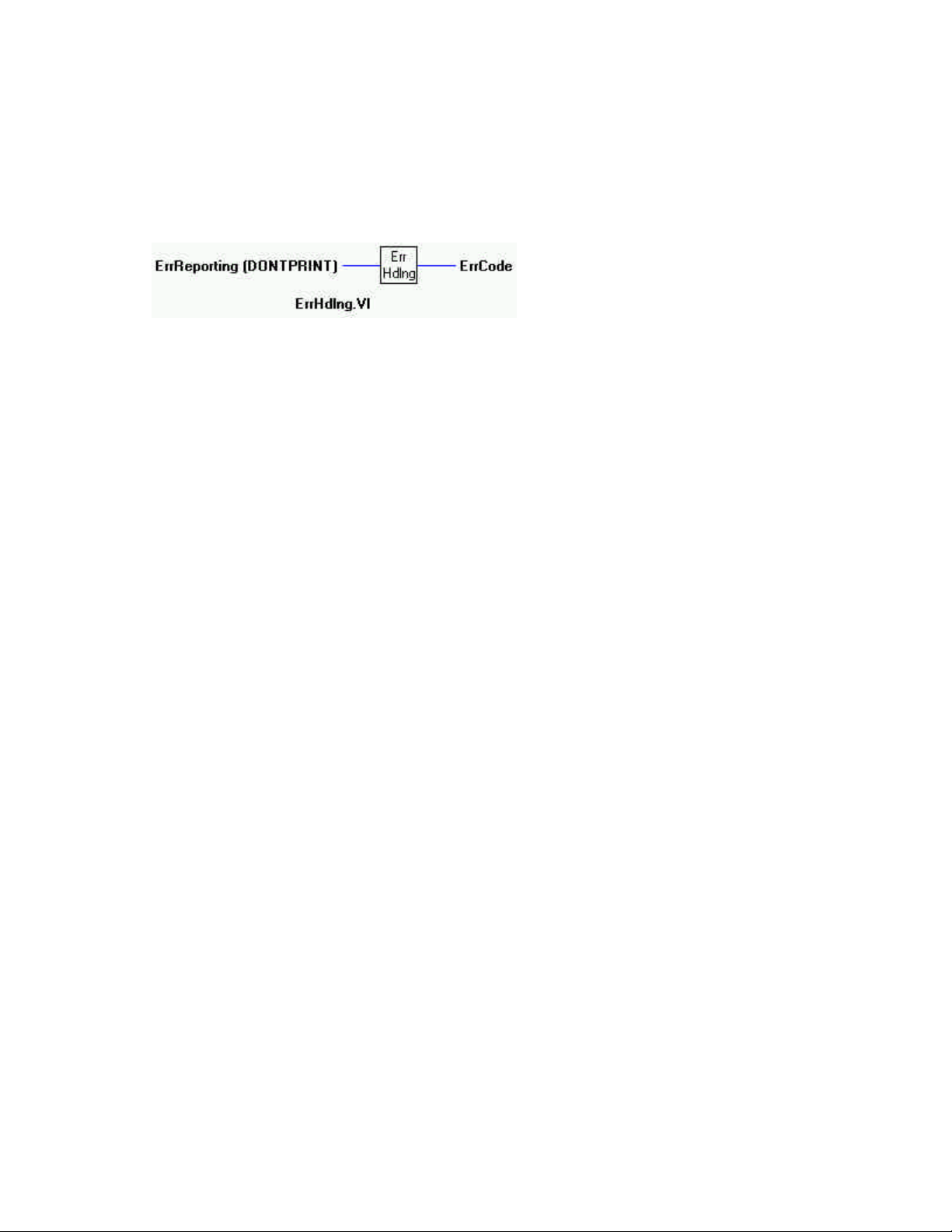
ErrHdlng.VI
Description:
Sets the error handling for all subsequent VI calls. Most VIs return error codes after each call. In addition other error handling features have been built into the library. This VI controls those features. If the UL LabVIEW Extension cannot find the configuration
file CB.CFG, it always terminates the program regardless of the ErrHdlng setting.
Summary:
Input: ErrReporting [I32] - type of error reporting.
Output: ErrCode [I32] - Error code
Explanation of the Arguments:
Warnings vs Fatal Errors - All errors that can occur are classified as either "warnings" or "fatal". Errors that can occur in normal
operation in a bug free program (disk is full, too few samples before trigger occurred) are classified as "warnings". All other errors
indicate a more serious problem and are classified as "fatal".
ErrReporting - This argument controls when the library will print error messages on the screen. The default is DONTPRINT. If it is
set to:
DONTPRINT - Errors will not generate a message to the screen. In that case your program must always check the returned error
code after each library call to determine if an error occurred.
PRINTWARNINGS - Only warning errors will generate a message to the screen. Your program will have to check for fatal errors.
PRINTFATAL - Only fatal errors will generate a message to the screen. Your program must check for warning errors.
PRINTALL - All errors will generate a message to the screen.
59
Page 64
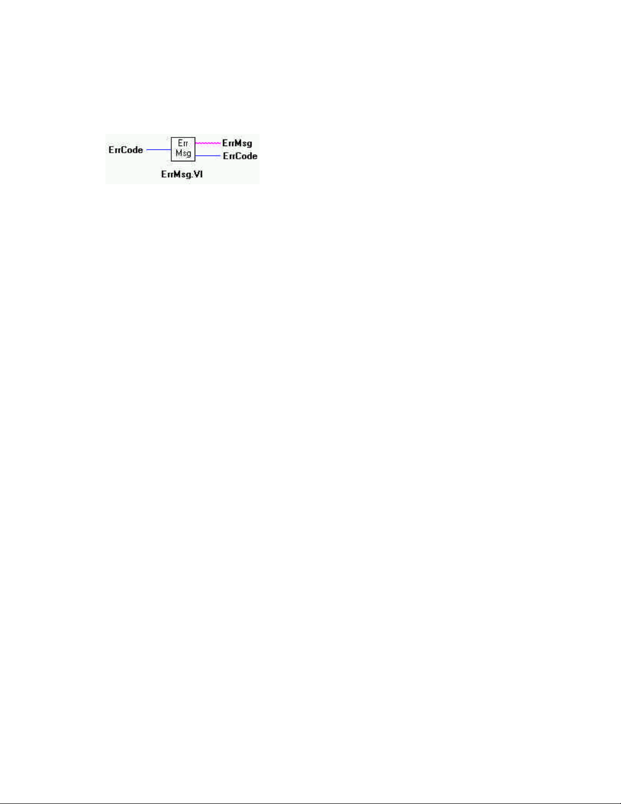
ErrMsg.VI
Description:
Returns the error message associated with an error code. Each VI returns an error code. If the error code is not equal to 0 it indicates
that an error occurred. Call this VI to convert the returned error code to a descriptive error message.
Summary:
Input: ErrCode [I32] - error code that was returned by any VI.
Outputs: ErrMsg [abc] - error message returned here
ErrCode [I32] - error code or 0 if no error
60
Page 65
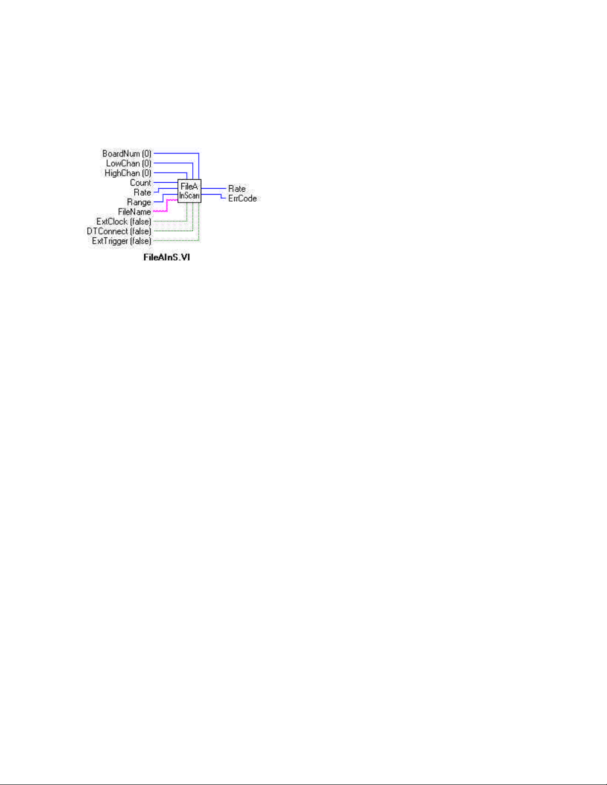
FileAInS.VI
Description:
Scan a range of A/D channels and store the samples in a disk file. This VI reads the specified number of A/D samples at the specified sampling rate from the specified range of A/D channels from the specified board. If the A/D board has programmable gain then
it sets the gain to the specified range. The collected data is returned to a file in binary format. Use FileRead.VI to load data from that
file into an array. See board specific info to determine if this function is supported on your board.
Summary:
Inputs: BoardNum [U32] - The board number when installed with InstaCal. Can be 0 to 100.
LowChan [I32] - First A/D channel of scan
HighChan [I32] - Last A/D channel of scan
Count [I32] - Number of samples to collect
Rate [I32] - Sample rate in samples per second (Hz) per channel
Range [I32] - Range code
FileName [abc] - Name of disk file
Extclock [TF] - External (T) or internal clock (F)
DTConnect [TF] - DT connect option (T). No DTConnect is (F)
ExtTrigger [TF] - External trigger (T). Internal is (F).
Outputs: Rate - Actual sampling rate
ErrCode - Error code
Explanation of the Arguments:
BoardNum - refers to the board number associated with the board when it was installed with the configuration program. The specified board must have an A/D.
Low/High Channel # - The maximum allowable channel depends on which type of A/D board is being used. For boards that have
both single ended and differential inputs the maximum allowable channel number also depends on how the board is configured (8
channels for differential, 16 for single-ended).
Count - Specifies the total number of A/D samples that will be collected. If more than one channel is being sampled then the number
of samples collected per channel is equal to Count / (HighChan − LowChan + 1).
Rate - The maximum sampling rate depends on the A/D board that is being used.
61
Page 66

Range - If the selected A/D board does not have a programmable range feature, then this argument will be ignored. Otherwise the
gain can be set to any of the following ranges that are supported by the selected A/D board. Refer to board specific information for
the list of ranges supported by each board.
BIP10VOLTS +/- 10 volts UNI10VOLTS 0 to 10 volts
BIP5VOLTS +/- 5 volts UNI5VOLTS 0 to 5 volts
BIP2PT5VOLTS +/- 2.5 volts UNI2PT5VOLTS 0 to 2.5 volts
BIP1PT67VOLTS +/- 1.67 volts UNI2VOLTS 0 to 2 volts
BIP1PT25VOLTS +/- 1.25 volts UNI1PT67VOLTS 0 to 1.67 volts
BIP1VOLTS +/- 1 volts UNI1PT25VOLTS 0 to 1.25 volts
BIPPT625VOLTS +/- 0.625 volts UNI1VOLTS 0 to 1 volts
BIPPT5VOLTS +/- 0.5 volts UNIPT1VOLTS 0 to 0.1 volts
BIPPT1VOLTS +/- 0.1 volts UNIPT01VOLTS 0 to 0.01 volts
BIPPT05VOLTS +/-0.05 volts MA4TO20 4 to 20 mA
BIPPT01VOLTS +/- 001 volts MA2TO10 2 to 10 mA
BIPPT005VOLTS +/- 0.005 volts MA1TO5 1 to 5 mA
MAPT5TO2PT5 0.5 to 2.5 mA
FileName - The named file must already exist. It should have been previously created with the MAKESTRM.EXE program.
ExtClock - If this option is used then conversions will be controlled by the signal on the trigger input line rather than by the internal
pacer clock. Each conversion will be triggered on the appropriate edge of the trigger input signal (see board specific info). When this
option is used the Rate argument is ignored. The sampling rate is dependent on the trigger signal.
DTConnect - If True, samples are sent to the DT-Connect port if the board is equipped with one. If False, samples are not output to
the DT-Connect port. This is the default.
OVERRUN Error - This error indicates that the data was not written to the file as fast as the data was sampled. Consequently some
data was lost. The value returned from FileInfo.VI in TotalCount will be the number of points successfully collected.
VERY IMPORTANT NOTE
In order to understand the functions, you must read the Board Specific Information section found in the Universal
Library user's guide. The example programs should be examined and run prior to attempting any programming of
your own. Following this advice will save you hours of frustration, and possibly time wasted holding for technical
support.
62
Page 67
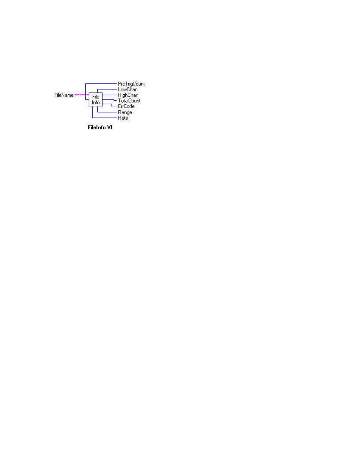
FileInfo.VI
Description:
Returns information about a streamer file. When FileAInS.VI or FilePret.VI fill the streamer file, information is stored about how
the data was collected (sample rate, channels sampled etc.). This VI returns that information. See board specific info to determine if
this function is supported on your board.
Summary:
Inputs: FileName [abc] - Name of streamer file
Outputs: PreTrigCount [I32] - Number of pre-trigger points collected
LowChan [I32] - Low A/D channel of scan
HighChan [I32] - High A/D channel of scan
TotalCount [I32] - Total number of points collected
ErrCode [I32] - Error code
Range [I32] - Range of A/D when data was collected
Rate [I32] - Sampling rate when data was collected
Explanation of the Arguments:
FileName - A file that must already have been created with the MAKESTRM.EXE application. Refer to documentation on the
MAKESTRM utility for more details.
63
Page 68
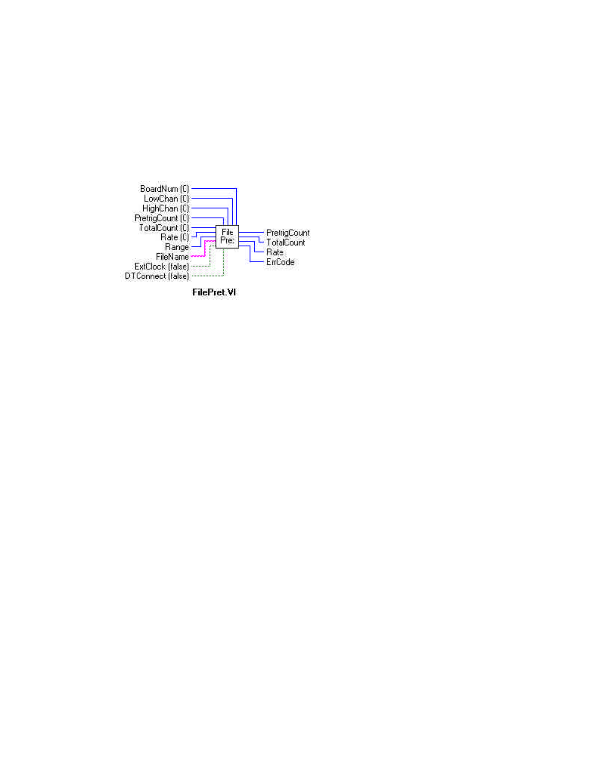
FilePret.VI
Description:
Scan a range of channels continuously while waiting for a trigger. After the trigger occurs, return the specified number of samples
including the specified number of pre-trigger samples to a disk file. This VI waits for a trigger signal to occur on the Trigger Input.
After the trigger occurs, it returns the specified number (TotalCount) of A/D samples including the specified number of pre-trigger
points. It collects the data at the specified sampling rate (Rate) from the specified range (LowChan-HighChan) of A/D channels from
the specified board. If the A/D board has programmable gain then it sets the gain to the specified range. The collected data is
returned to a file. See board specific info to determine if this function is supported by your board.
Summary:
Inputs: BoardNum [U32] - The board number when installed with InstaCal. Can be 0 to 100.
LowChan [I32] - First A/D channel of scan
HighChan [I32] - Last A/D channel of scan
PretrigCount [I32] - Number of pre-trigger samples to collect.
TotalCount [I32] - Total number of samples to collect.
Rate [I32] - Sample rate in samples per second (Hz) per channel
Range [I32] - A/D Range
FileName [abc] - Name of disk file
ExtClock [TF] - External (T) or internal clock (F - default)
DTConnect [TF] connect option (T)
Outputs: PretrigCount [I32]- Number of pre-trigger sample collected.
TotalCount [I32]- Total number of samples collected.
Rate [I32]- Actual sampling rate
ErrCode [I32]- error code
Explanation of the Arguments:
BoardNum - refers to the board number associated with the board when it was installed with the configuration program. The specified board must have an A/D and pretrigger capability.
Low/High Channel # - The maximum allowable channel depends on which type of A/D board is being used. For boards that have
both single ended and differential inputs the maximum allowable channel number also depends on how the board is configured (8
channels for differential, 16 for single ended).
PretrigCount - Specifies the number of samples before the trigger that will be returned. PretrigCount must be less than 16000 and
PreTrigCount must also be less than TotalCount − 512.
If the trigger occurs too early, then fewer than the requested number of pre-trigger samples will be collected. In that case a
TOOFEW error will occur. The PretrigCount will be set to indicate how many samples were collected and the post trigger samples
will still be collected.
64
Page 69

TotalCount - Specifies the total number of samples that will be collected and stored in the file. TotalCount must be greater then or
equal to PretrigCount + 512. If the trigger occurs too early then fewer than the requested number of samples will be collected. In that
case a TOOFEW error will occur. The TotalCount will be set to indicate how many samples were actually collected.
Rate - The maximum sampling rate depends on the A/D board that is being used. This is the rate at which scans are triggered. If you
are sampling four channels, 0 to 3, then specifying a rate of 10,000 scans per second (10 kS/s) will result in the A/D converter rate of
40 kS/s (four channels at 10,000 samples per channel per second). This is different from some software where you specify the total
A/D chip rate. In those systems, the per channel rate is equal to the A/D rate divided by the number of channels in a scan. This
argument also returns the value of the actual set. This may be different from the requested rate because of pacer limitations.
Range - If the selected A/D board does not have a programmable range feature, then this argument is ignored. Otherwise the gain
can be set to any of the following ranges that are supported by the selected A/D board. Refer to board specific information for the list
of ranges supported by each board.
BIP10VOLTS +/- 10 volts UNI10VOLTS 0 - 10 volts
BIP5VOLTS +/- 5 volts UNI5VOLTS 0 - 5 volts
BIP2PT5VOLTS +/- 2.5 volts UNI2PT5VOLTS 0 - 2.5 volts
BIP1PT67VOLTS +/- 1.67 volts UNI2VOLTS 0 - 2 volts
BIP1PT25VOLTS +/- 1.25 volts UNI1PT67VOLTS 0 - 1.67 volts
BIP1VOLTS +/- 1 volts UNI1PT25VOLTS 0 - 1.25 volts
BIPPT625VOLTS +/- 0.625 volts UNI1VOLTS 0 - 1 volts
BIPPT5VOLTS +/- 0.5 volts UNIPT1VOLTS 0 - 0.1 volts
BIPPT1VOLTS +/- 0.1 volts UNIPT01VOLTS 0 - 0.01 volts
BIPPT05VOLTS +/-0.05 volts MA4TO20 4 - 20 mA
BIPPT01VOLTS +/- 001 volts MA2TO10 2 - 10 mA
BIPPT005VOLTS +/- 0.005 volts MA1TO5 1 - 5 mA
MAPT5TO2PT5 0.5 - 2.5 mA
FileName - The named file must already exist. It should have been previously created with the MAKESTRM.EXE program.
EXTCLOCK - If this option is used then conversions will be controlled by the signal on the trigger input line rather than by the
internal pacer clock. Each conversion will be triggered on the appropriate edge of the trigger input signal (see board specific info).
When this option is used the Rate argument is ignored. The sampling rate is dependent on the trigger signal.
DTCONNECT - If True, samples are sent to the DT-Connect port if the board is equipped with one. If False, samples are not output
to the DT-Connect port. This is the default.
OVERRUN Error - This error indicates that the data was not written to the file as fast as the data was sampled. Consequently some
data was lost. The value in TotalCount will be the number of points that were successfully collected.
65
Page 70
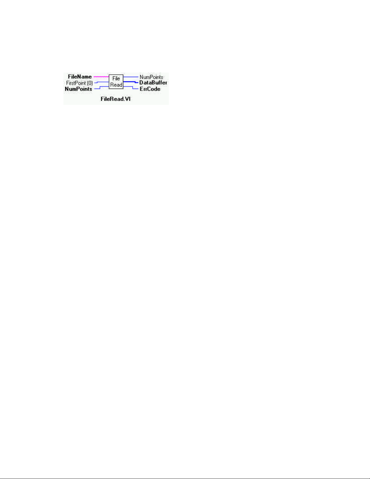
FileRead.VI
Description:
Reads data from a streamer file. See board specific info to determine if supported on your board.
Summary:
Inputs: FileName [abc] - Name of streamer file
FirstPoint [I32] - Index of first point to read
NumPoints [I32] - Number of points to read
Outputs: NumPoints [I32] - Number of points read
DataBuffer [I32] - Data buffer that data was read into.
ErrCode [I32] - error code
Explanation of the Arguments:
Data Format - The data is returned as 16 bits. The 16 bits can represent 12 bits of analog, 12 bits of analog plus 4 bits of channel, or
16 bits of analog. Use ACvtData.VI to correctly load the data into an array.
Loading Portions of Files - The file can contain much more data than can fit in DataBuffer. In those cases use TotalCount and
FirstPoint to read a selected piece of the file into DataBuffer. Call FileInfo.VI first to find out how many points are in the file.
66
Page 71
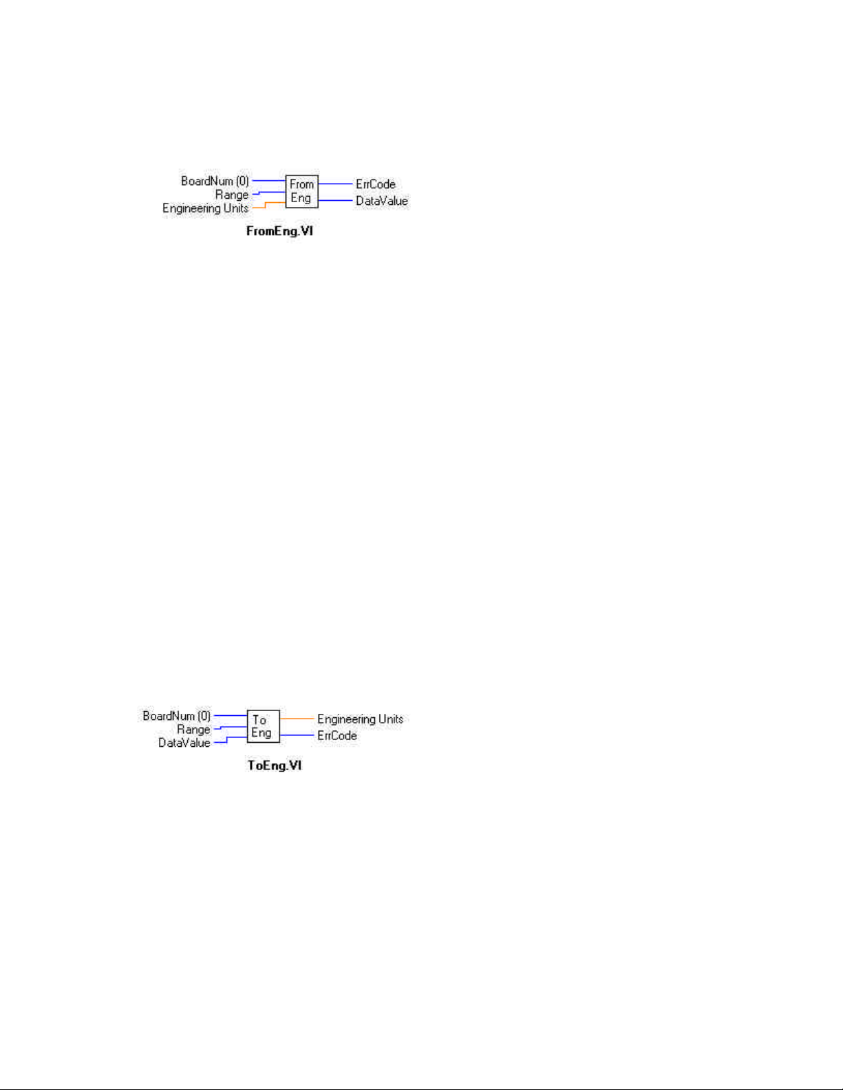
FromEng.VI
Description:
Converts a voltage (or current ) in engineering units to a D/A count value for output to a D/A.
Summary:
Arguments: BoardNum [U32] - The board number when installed with InstaCal. Can be 0 to 100.
Range [I32] - D/A range to use in conversion
EngUnits [SGL] - Voltage (or current) value to convert
DataVal [I16] - D/A count equivalent to voltage returned here
ErrCode [I32] - error code
Explanation of the Arguments:
BoardNum - refers to the board number associated with the D/A board when it was installed. This function uses the board number to
determine whether to do a 12-bit or 16-bit conversion.
Range - D/A voltage (or current) range. Some D/A boards have programmable voltage ranges, others set the voltage range via
switches on the board. In either case the selected range must be passed to this function. Each D/A board supports different voltage
and/or current ranges. Refer to the board's hardware manual for a list of allowed ranges used by the board.
EngUnits - The voltage (or current) value that you wish to set the D/A to. This value should be within the range specified by the
Range argument.
DataVal - The function returns a D/A count to this variable that is equivalent to the EngUnits argument.
ToEng.VI
Description: Converts an A/D count value to an equivalent voltage value.
Summary:
Arguments: BoardNum - Board number, can be 0 to 100 if installed with InstaCal.
Range - A/D range to use in conversion
DataVal - A/D count value returned from an A/D board
EngUnits - Equivalent voltage (or current) value returned to this variable
ErrCode - error code
Explanation of the Arguments:
BoardNum - refers to the board number associated with the A/D board when it was installed. This function uses the board number to
determine whether to do a 12-bit or 16-bit conversion.
67
Page 72

Range - A/D voltage (or current) range. Some A/D boards have programmable voltage ranges, others set the voltage range via
switches on the board. In either case the selected range must be passed to this function. Each A/D board supports different voltage
and/or current ranges. Refer to the board's hardware manual for a list of allowed ranges used by the board.
DataVal - A/D count returned from an A/D board.
EngUnits - The voltage (or current) value that is equivalent to DataVal is returned to this variable. The value will be within the
range specified by the Range argument.
68
Page 73
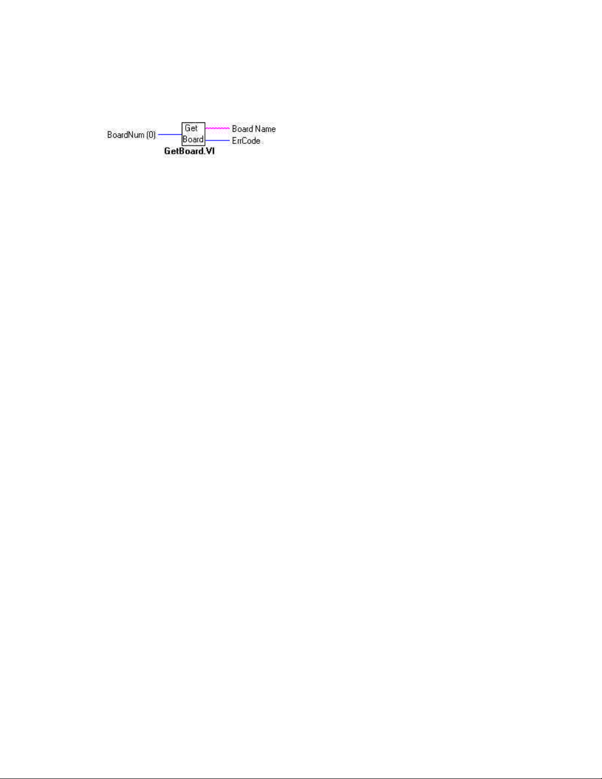
GetBoard.VI
Description:
Returns the boardname of a specified board.
Summary:
Arguments: BoardNum [U32] - The board number when installed with InstaCal. Can be 0 to 100, or GETFIRST or GETNEXT
BoardName [abc] - Board name string returned to this variable
ErrCode [I32] - error code
Explanation of the Arguments:
BoardNum - refers to the board number associated with a board when it was installed or GETFIRST or GETNEXT.
BoardName - A string variable that the board name will be returned to. This string variable must be pre-allocated to be at least as
large as BOARDNAMELEN. This size is guaranteed to be large enough to hold the longest board name string.
NOTES:
There are two distinct ways of using this function. The first is to pass a board number as the Board argument. In that case the string
that is returned will describe the board type of the installed board.
The other way to use the function is to set Board to GETFIRST(-2) or GETNEXT(-3) to get a list of all board types that are supported by the library. If Board is set to GETFIRST it will return the first board type in the list of supported boards. Subsequent calls
with Board=GETNEXT will return each of the other board types supported by the library. When you reach the end of the list BoardName will be set to an empty string.
69
Page 74
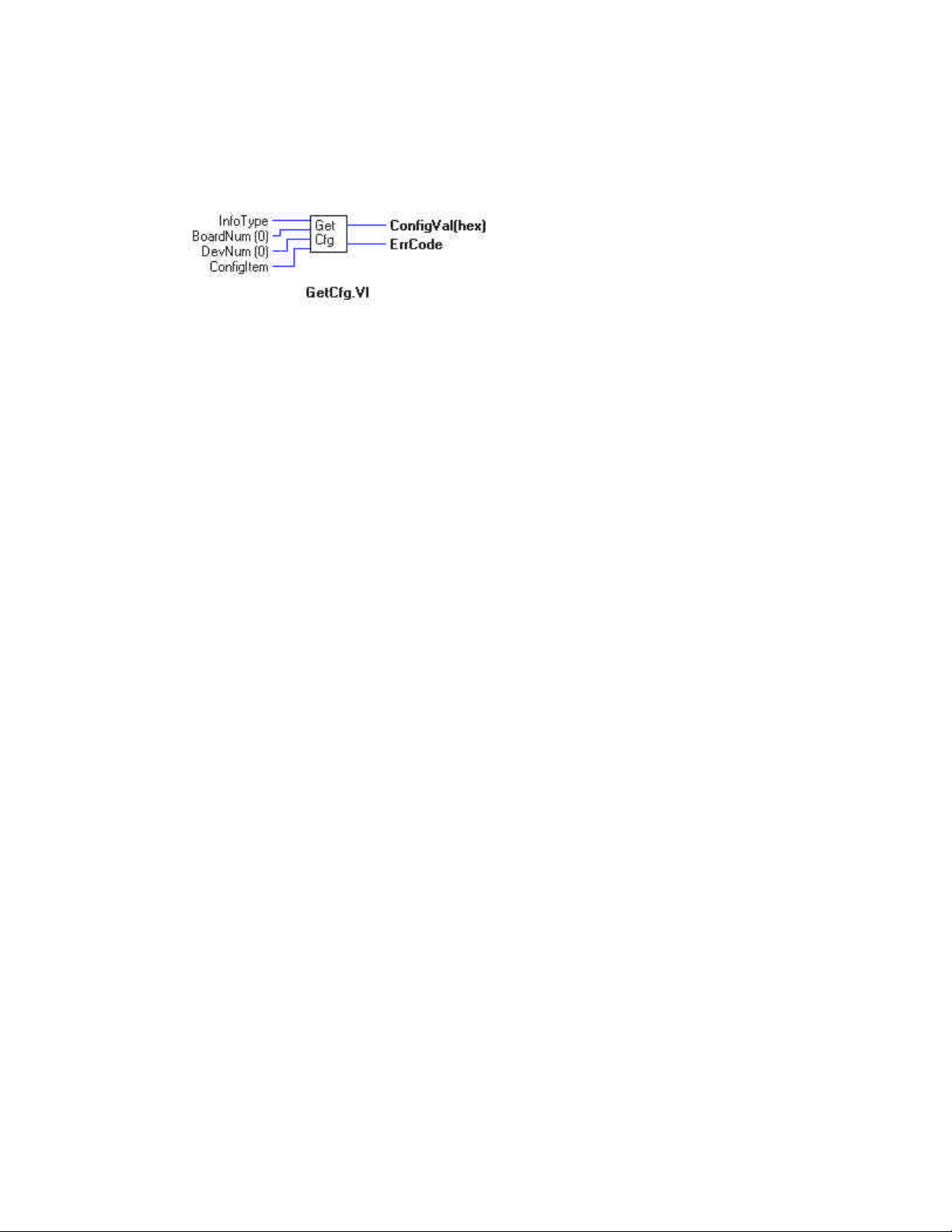
GetCfg.VI
Description:
Returns a configuration option for a board. The configuration information for all boards is stored in the CB.CFG file. This information is loaded from CB.CFG by all programs that use the library. The current configuration can be changed within a running program with the SetCfg VI function. This GetCfg VI returns the current configuration information.
Summary:
Arguments: InfoType [I32] - Which class of configuration information you want to retrieve
BoardNum [I32] - Board name (0-9)
DevNum [I32] - Specifies which device within board
ConfigItem [I32] - Specifies which configuration item
ConfigVal [I32] - Current configuration value returned here
ErrCode [I32] - error code
Explanation of the Arguments:
InfoType - The configuration information for each board is grouped into different categories. This argument specifies which category
you want. It should be set to one of the following constants:
GLOBALINFO - Information about the configuration file
BOARDINFO - general information about a board
DIGITALINFO - information about a digital device
COUNTERINFO - information about a counter device
EXPANSIONINFO - information about an expansion device
MISCINFO - One of the miscellaneous options for the board
BoardNum - refers to the board number associated with a board when it was installed.
DevNum - Selects a particular device. If InfoType=DIGITALINFO then DevNum specifies which of the board's digital devices you
want information on. If InfoType=COUNTERINFO then DevNum specifies which of the board's counter devices.
ConfigItem - Specifies which configuration item you wish to retrieve. Refer to the table below for a list of all of the possible values
for ConfigItem.
ConfigVal - The specified configuration item is returned to this variable.
70
Page 75

NOTES:
The list of ConfigItem values for each category of configuration information is:
InfoType = GLOBALINFO
GIVERSION - CB.CFG file format. This information is used by the library to determine compatibility.
GINUMBOARDS - Maximum number of installable boards
GINUMEXPBOARDS - Maximum number of expansion boards allowed to be installed.
InfoType = BOARDINFO
BIBASEADR - Base address of board
BIBOARDTYPE - Returns a number in the range of 0 to 8000 Hex.
BIINTLEVEL - Interrupt level. 0 for none or 1 - 15
BIDMACHAN - DMA channel. 0, 1 or 3
BIINITIALIZED - TRUE (non-zero) or FALSE (0)
BICLOCK - Clock frequency in MHz (1, 4, 6, or 10); or (0) for not supported.
BIRANGE - Selected voltage range. For switch-selectable gains only.
BIRANGE: If the selected A/D board does not have a programmable gain feature then this argument returns the
range as defined by the installed InstaCal settings, which, if InstaCal and the board were installed correctly, corresponds to the input range as set via the switches on the board. Refer to board specific information for a list of the
A/D ranges supported by each board.
Library Name Range BIRANGE # Library Name Range BIRANGE #
BIP10VOLTS +/- 10 volts 1 UNI10VOLTS 0 to 10 volts 100
BIP5VOLTS +/- 5 volts 0 UNI5VOLTS 0 to 5 volts 101
BIP2PT5VOLTS +/- 2.5 volts 2 UNI2PT5VOLTS 0 to 2.5 volts 102
BIP1PT25VOLTS +/- 1.25 volts 3 UNI2VOLTS 0 to 2 volts 103
BIP1VOLTS +/- 1 volts 4 UNI1PT25VOLTS 0 to 1.25 volts 104
BIPPT625VOLTS +/- 0.625 volts 5 UNI1VOLTS 0 to 1 volts 105
BIPPT5VOLTS +/- 0.5 volts 6 UNIPT1VOLTS 0 to 0.1 volts 106
BIPPT1VOLTS +/- 0.1 volts 7 UNIPT01VOLTS 0 to 0.01 volts 107
BIPPT05VOLTS +/-0.05 volts 8 UNI1PT67VOLTS 0 to 1.67 volts 108
BIPPT01VOLTS +/- 001 volts 9 MA4TO20 4 to 20 mA 200
BIPPT005VOLTS +/- 0.005 volts 10 MA2TO10 2 to 10 mA 201
BIP1PT67VOLTS +/-1.67 volts 11 MA1TO5 1 to 5 mA 202
MAPT5TO2PT5 0.5 to 2.5 mA 203
BINUMADCHANS - Number of A/D channels
BIUSESEXPS - Supports expansion boards TRUE/FALSE
BIDINUMDEVS - Number of digital devices
BIDIDEVNUM - Index into digital information for first device
BICINUMDEVS - Number of counter devices
BICIDEVNUM - Index into counter information for first device
BINUMDACHANS - Number of D/A channels
BIWAITSTATE - Setting of Wait State jumper. 1 = enabled, 0 = disabled
BINUMIOPORTS - Number of IOPorts used by board
BIPARENTBOARD - Board number of parent board
BIDTBOARD - Board number of connected DT board
InfoType = DIGITALINFO
DIBASEADR - Base address
DIINITIALIZED - TRUE (non-zero) or FALSE (0)
DIDEVTYPE - Device Type - AUXPORT, FIRSTPORTA etc
DIMASK - Bit mask for this port
DIREADWRITE - Read required before write TRUE/FALSE
DICONFIG - Current configuration INPUT or OUTPUT
DINUMBITS - Number of bits in port
DICURVAL - Current value of outputs
71
Page 76

InfoType = COUNTERINFO
CIBASEADR - Base address
CIINITIALIZED - TRUE (non-zero) or FALSE (0)
CICTRTYPE - 1 = 8254, 2 = 9513 , 3 = 8536, 4 = 7266 type counter chip.
CICTRNUM - Which counter on chip
CICONFIGBYTE - Configuration byte
InfoType = EXPANSIONINFO
XIBOARDTYPE - Board type
XIMUXADCHAN1 - A/D channel board is connect to
XIMUXADCHAN2 - 2nd A/D channel board is connected to
XIRANGE1 - Range (gain) of low 16 channels
XIRANGE2 - Range (gain) of high 16 channels
XICJCCHAN - A/D channel that CJC is connected to
XITHERMTYPE - Thermocouple type
XINUMEXPCHANS - Number of expansion channels on board
XIPARENTBOARD - Board number of parent A/D board
72
Page 77
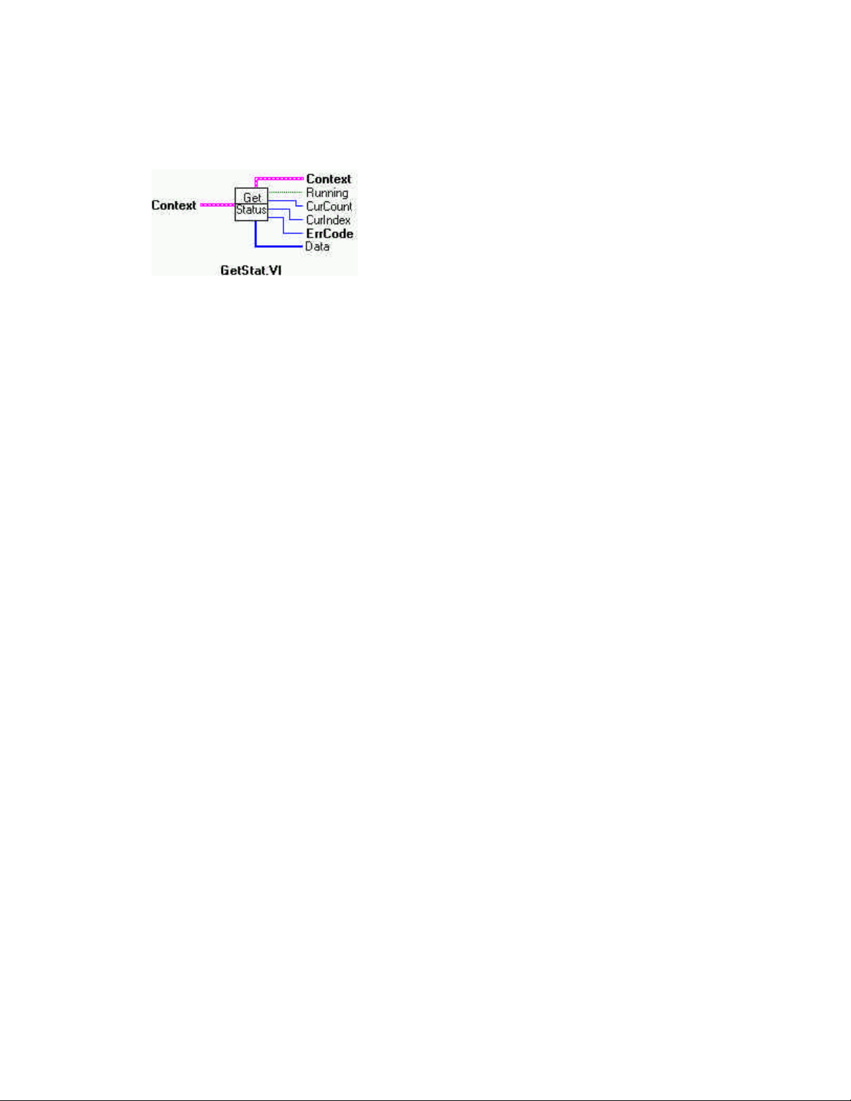
GetStatus.VI
Description:
Returns status about background operation currently running
Summary:
Inputs: Context [cluster] - Input data structure from a background operation. *NOTE
Outputs: Context [cluster] - Output data structure
Running [TF] - Status of background operation.
CurCount [I32] - current count returned to this variable.
CurIndex [I32] - current index returned to this variable.
ErrCode [I32] -Error code
Data [U16] - Data array from context
Explanation of the Arguments:
Context - Data structure containing information from a background operation. Some of the information included is the board
number, the data array, the array size, and the initial status of the background operation.
NOTE:
Wiring of this VI should conform to the following pattern: Start a background operation. GetStat.VI checks for completion (boolean
output called "Running"). StopBg.VI terminates the operation, if not already done, and frees memory aliases. Data output from the
background operation is passed to GetStat.VI and StopBg.VI via "Context", and can be wired from one or both of them for intermediate or final actions, respectively. The demo VIs illustrate this process effectively.
Running - Indicates whether or not a background process is currently executing. Idle is False.
CurCount - Specifies how many points have been input or output. It can be used to gauge how far along the operation is towards
completion. Generally the CurCount will return the total number of samples collected at the time of the call to cbGetStatus(). However, in cases where CONTINUOUS and BACKGROUND options are both set, the way that CurCount behaves will depend on board
type and transfer mode. This value may recycle as the circular buffer recycles, or may continuously increment with the number of
counts transferred. Also, CurCount may not update on each sample. For example, when running in BLOCKIO mode, CurCount
updates after each packet of data has been transferred. The packet size is board dependent. Refer to board specific information for
details.
CurIndex - This is an index into the data buffer that points at the start of the last completed channel scan. This can be used to provide a real- time display for a background operation. DataBuffer [CurIndex] points to the start of the last complete channel scan that
was put in or taken out of the buffer. You should expect CurIndex to increment by the number of channels in the scan as well. If no
points in the buffer have been accessed yet then CurIndex will equal -1. This value can also behave differently in cases where CONTINUOUS and BACKGROUND options are both set (see CurCount description). Refer to board specific information for details.
If you use the CONVERTDATA option with either the CONTINUOUS option or with pre-triggering functions then CurIndex will
return the index of the last A/D sample, rather than the start of the last completed channel scan.
For many background operations CurCount = CurIndex. For Pre-Trigger inputs though, they are different. If the hardware allows
background trigger operations, CurCount indicates how many points of the TotalCount have been collected. CurCount will rise to
PreTrigCount, stop until the trigger occurs then rise to TotalCount. CurIndex though will constantly increase and reset as it goes
around and around the circular buffer while waiting for the trigger to occur.
73
Page 78
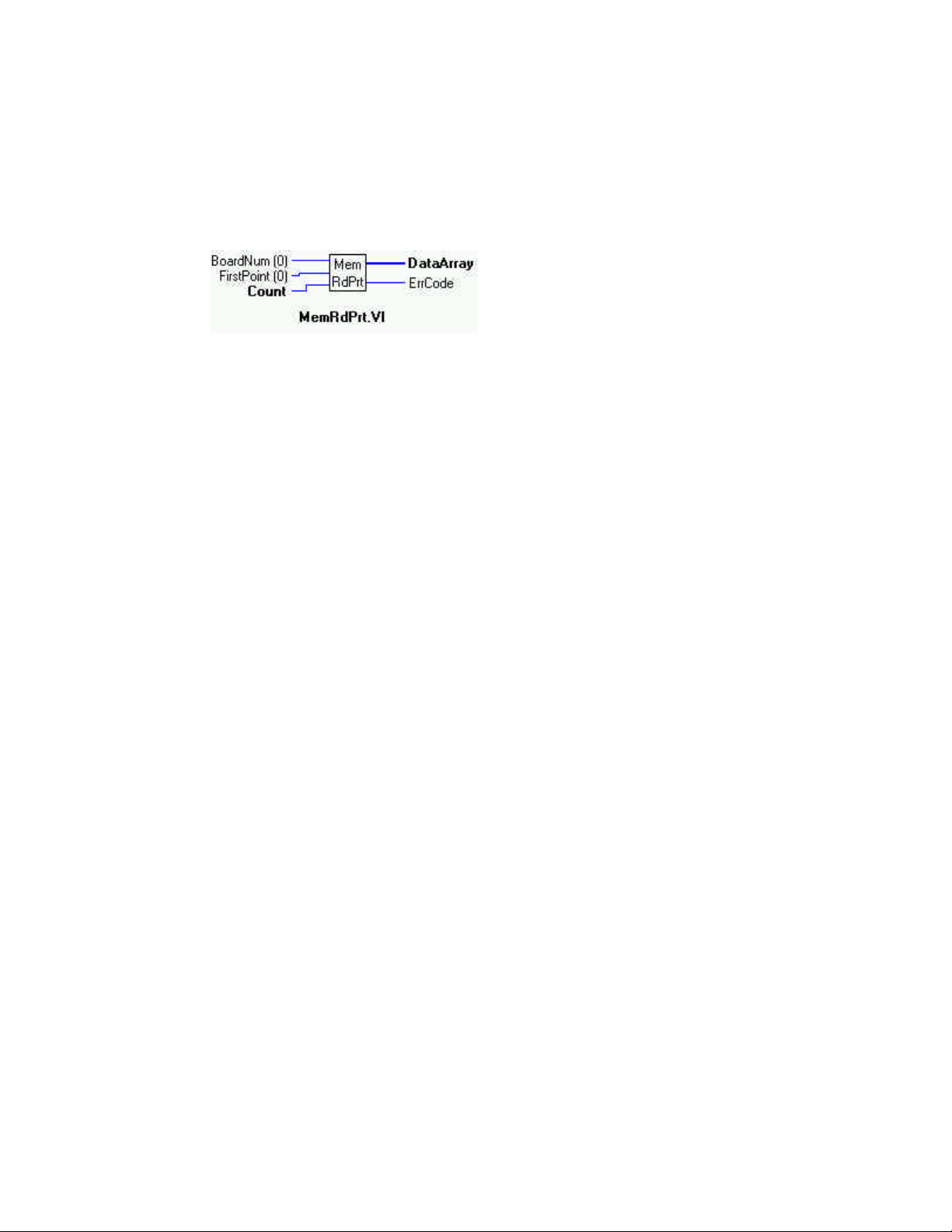
MemRdPrt.VI
Description:
Reads pre-trigger data from a memory board that has been collected with the APretrxx.VI and arranges the data in the correct order
(pre-trigger data first, then post-trigger data). This VI can only be used to retrieve data that has been collected with the APretrxx.VI
with the ExtMemory option set to TRUE. After each APretrxx call, all data must be unloaded from the memory board with this VI.
If any more data is sent to the memory board then the pre-trigger data will be lost.
Summary:
Inputs: BoardNum [U32] - board number, can be 0 to 100 when entered with InstaCal..
FirstPoint [I32] - Index of first point to read or FROMHERE.
Count [U32] - Number of points (words) to read
Outputs: DataArray [U16] - Output data array
ErrCode [I32] - Error code
Explanation of the Arguments:
BoardNum - refers to the board number associated with a board when it was installed.
FirstPoint - Use the FirstPoint argument to specify the first point to be read. For example, to read points #200 - #250, set
FirstPoint=200 and Count=50.
If you are going to read a large amount of data from the board in small chunks then set FirstPoint to FROMHERE (-1) to read each
successive chunk. Using FROMHERE (-1) speeds up the operation of MemRdPrt.VI when working with large amounts of data.
DT Connect Conflicts - The .MemRdPrtVI can not be called while a DT Connect transfer is in progress. For example, if you start
collecting A/D data to the memory board in the background (by calling AInScxx with the DTCONNECT + BACKGROUND
options), you can not call .MemRdPrtVI until the AInScxx has completed. If you do, you will get a DTACTIVE error.
74
Page 79
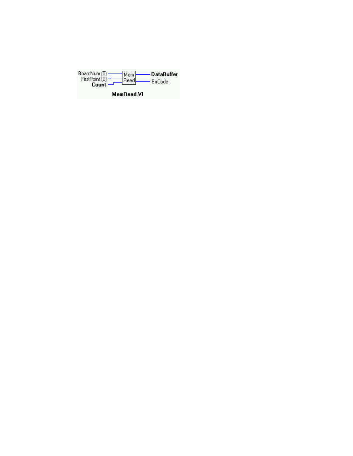
MemRead.VI
Description:
Reads data from a memory board into an array.
Summary:
Inputs: BoardNum [U32] - board number, can be 0 to 100 when entered with InstaCal..
FirstPoint [I32] - Index of first point to read or FROMHERE.
Count [U32] - Number of points (words) to read
Outputs: DataBuffer [U16]- Output data array
ErrCode [I32] - Error Code
Explanation of the Arguments:
BoardNum - refers to the board number associated with a board when it was installed.
FirstPoint - Use the FirstPoint argument to specify the first point to be read. For example, to read points #200 - #250, set
FirstPoint=200 and Count=50.
If you are going to read a large amount of data from the board in small portions, set FirstPoint to FROMHERE (-1) to read each successive portion. Using FROMHERE (-1) speeds up the operation of MemRead.VI when working with large amounts of data.
DT-CONNECT Conflicts - The MemRead.VI can not be called while a DT-CONNECT transfer is in progress. For example, if you
start collecting A/D data to the memory board in the background (by calling AInScxx.VI with the DTCONNECT + BACKGROUND options). You can not call MemRead.VI until the AInScxx.VI has completed. If you do, you will get a DTACTIVE error.
75
Page 80
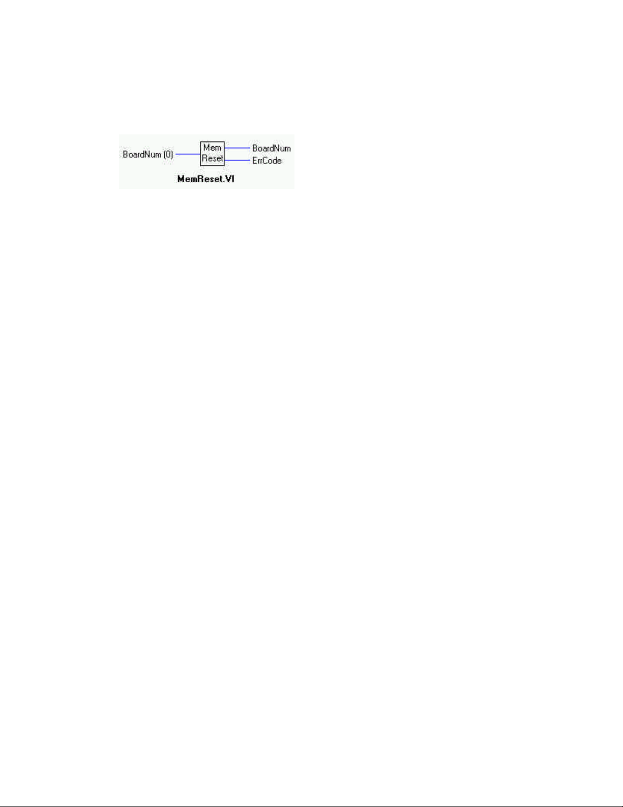
MemReset.VI
Description:
Resets the memory board pointer to the start of the data. The memory boards are sequential devices. They contain a counter which
points to the 'current' word in memory. Every time a word is read or written this counter increments to the next word.
Summary:
Input: BoardNum [U32] - board number, can be 0 to 100 when entered with InstaCal...
Outputs: BoardNum [U32] - board number, can be 0 to 100 when entered with InstaCal..
ErrCode [I32] - Error code
Explanation of the Arguments:
This VI is used to reset the counter back to the start of the memory. Between successive calls to AInScxx you would call this VI so
that the second AInScxx overwrites the data from the first call. Otherwise the data from the first AInScxx will be followed by the
data from the second AInScxx in the memory on the card.
Likewise, anytime you call MemRead or MemWrite it will leave the counter pointing to the next memory location after the data that
you read or wrote. Call MemReset to reset back to the start of the memory buffer before the next call to AInScxx.
76
Page 81
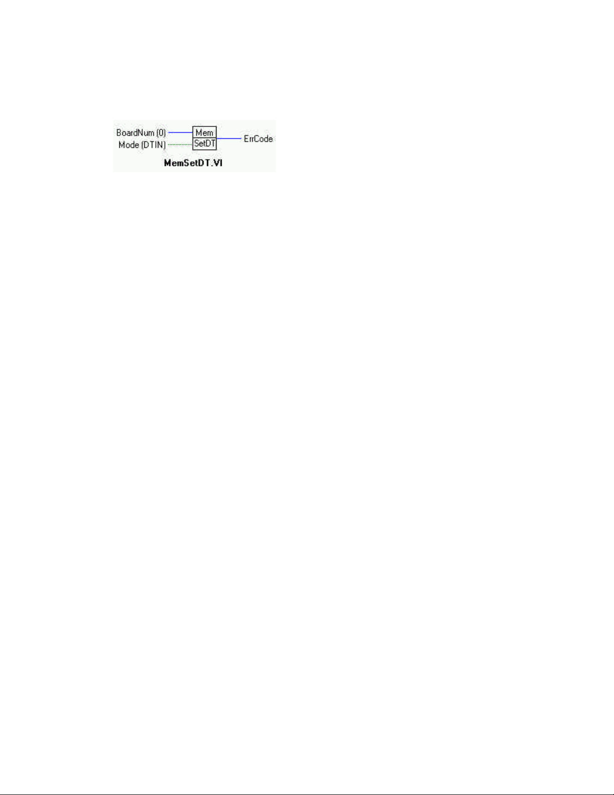
MemSetDT.VI
Description:
Sets the DT Connect Mode of a Memory Board
Summary:
Inputs: BoardNum [U32] - board number, can be 0 to 100 when entered with InstaCal.
Mode [TF] - Direction of memory board DT Transfer
Output: ErrCode [I32] -Error code
Explanation of the Arguments:
BoardNum - refers to the board number associated with a board when it was installed.
Mode - Must be set to either DTIN (default) or DTOUT. Set the Mode on the memory board to DTIN if you wish to transfer data
from an A/D board to the memory board. Set Mode=DTOUT (True) if you wish to transfer data from a memory board to a D/A
board.
This command only controls the direction of data transfer between the memory board and another board that is connected to it via a
DT Connect cable.
If using the EXTMEMORY option with AInScxx, etc., this VI should not be used. The memory board mode is already set through
AInScxx.EXTMEMORY option.
Use this VI only if the parent board is not supported by the Universal Library.
77
Page 82
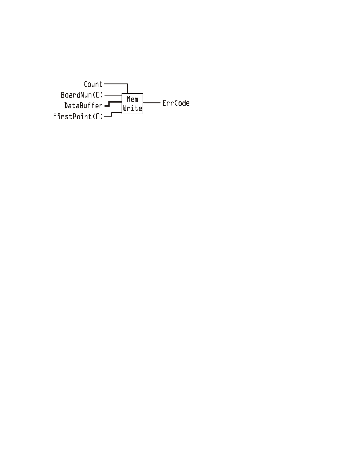
MemWrite.VI
Description:
Writes data from an array to the memory card
Summary:
Inputs: BoardNum [U32] - board number, can be 0 to 100 when entered with InstaCal..
DataBuffer [U16] - Pointer to the data array
FirstPoint [I32] - Index of first point to write or FROMHERE.
Count [I32] - Number of points (words to write)
Output: ErrCode [I32] - Error code
Explanation of the Arguments:
BoardNum - refers to the board number associated with a board when it was installed.
FirstPoint - Use the FirstPoint argument to specify where in the board's memory to write the first point. For example, to write to
locations #200 - #250, set FirstPoint=200 and Count=50.
If you are going to write a large amount of data to the board in small portions, set FirstPoint to FROMHERE (-1) to write each successive portion. Using FROMHERE (-1) speeds up the operation of MemWrite when working with large amounts of data.
DT Connect Conflicts - The MemWrite VI can not be called while a DT Connect transfer is in progress. For example, if you start
collecting A/D data to the memory board in the background (by calling AInScxx with the DTCONNECT + BACKGROUND
options). You can not call MemWrite until the AInScxx has completed. If you do you will get a DTACTIVE error.
Count - Specifies the number of words to be written to the external memory card. Count must be equal to or less than the size of
DataBuffer.
DataBuffer - Buffer containing data to be written to the external memory card.
78
Page 83
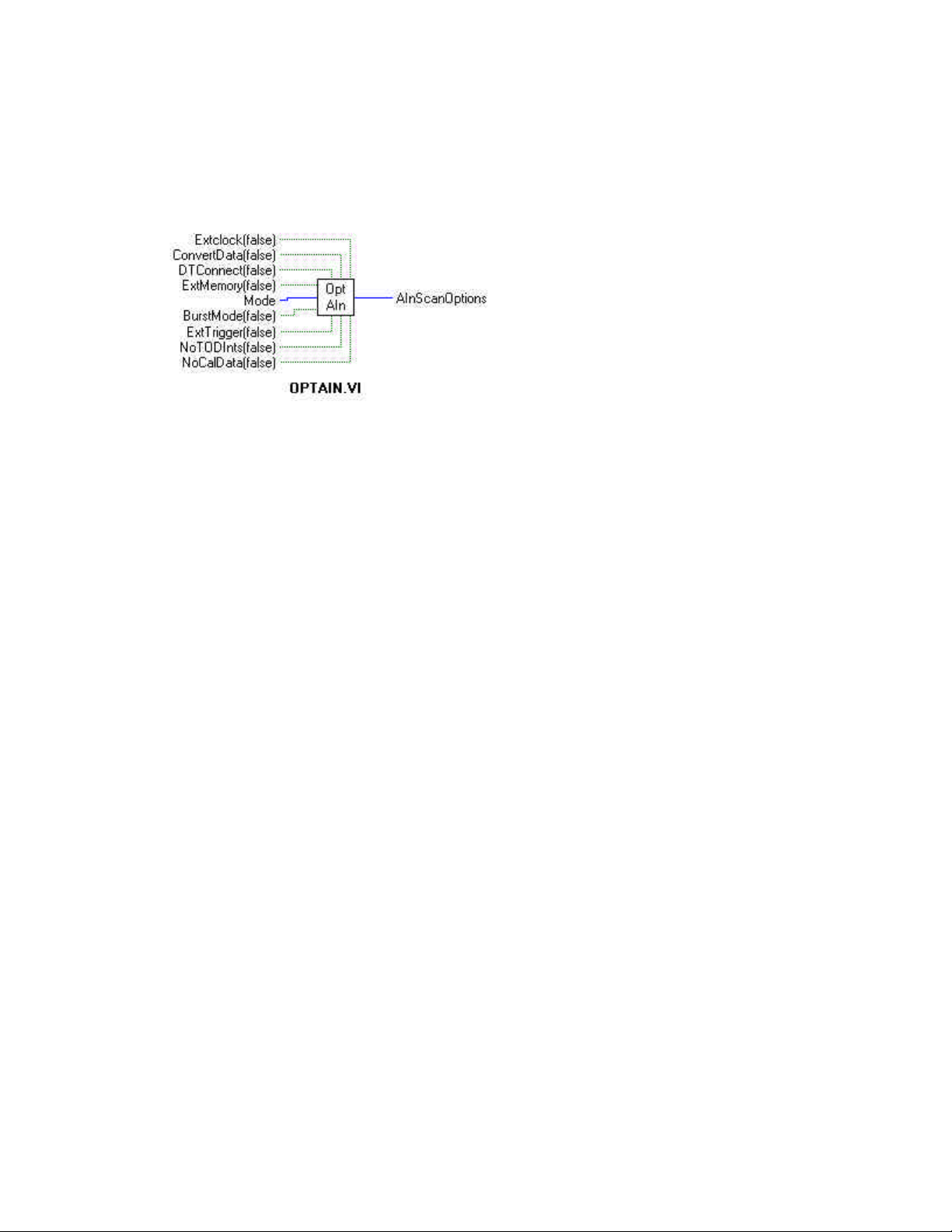
OptAIn.VI Changed R3.3ID
Description:
Generates option input for AInScxx VIs
Change at Rev.3.3 added NoCalibrateData option.
Summary:
Inputs: Extclock [TF] - External (T) or internal clock (F - “TIMED”)
ConvertData [TF] - Separate data and channel tags (T). (F = “NOCONVERTDATA”)
DTConnect [TF] - DT connect option (T). (F = “NODTCONNECT”)
ExtMemory [TF] - External memory option (Mega Fifo board) (T). (F = “NORMMEMORY”)
BurstMode [TF] - Burst mode option (board-specific) (T). (F = “NOBURSTMODE”)
ExtTrigger [TF] - External trigger option (T). (F = “NOEXTRIGGER”)
NoTODInts [TF] - Option to disable time of day interupts (T). (F = “TODInts”)
NoCalData [TF] - option to disable real time software calibration (T). (F = “CalData”)
Mode [I32] - Sampling mode used (T). (F = “DEFAULTIO”)
Output: AInScanOptions [I32] - Anded value of input options.
Explanation of the Arguments:
The output of this VI must be wired to the options input of the AInScFg VI or AInScBg VI.
ExtClock - If this option is used then conversions will be controlled by the signal on the trigger input line rather than by the internal
pacer clock. Each conversion will be triggered on the appropriate edge of the trigger input signal (see board-specific info). When this
option is used, the Rate argument is ignored. The sampling rate is dependent on the trigger signal. Options for the board will default
to a transfer mode that will allow the maximum conversion rate to be attained unless otherwise specified.
ConvertData - If the CONVERTDATA option is used for 12-bit boards then the data that is returned to data buffer (array) will automatically be converted to 12-bit A/D values. If NOCONVERTDATA is used, data from 12-bit A/D boards will be returned as 16-bit
values that will contain both a 12-bit A/D value and a 4-bit channel number. After the data collection is complete you can call ACvtData to convert the data after the fact. CONVERTDATA cannot be specified if you are using a background VI and DMA transfers.
This option is ignored for 16-bit boards.
DTConnect - All A/D values will be sent to the A/D board's DT CONNECT port. This option is incorporated into the EXTMEMORY option. Use DTCONNECT only when the external board is not supported by the Universal Library.
ExtMemory -Data is returned to a data buffer (array). EXTMEMORY causes the command to send the data to a connected memory
board via the DT-Connect interface rather than returning the data to data buffer (array). Everytime this option is used it overwrites
any data already stored in the memory board. The data should be unloaded with the MemRead VI before collecting new data.
Do not use EXTMEMORY and DTCONNECT together.
79
Page 84

BurstMode - Enables burst mode sampling. Scans from LowChan to HighChan are clocked at the maximum A/D rate between samples to minimize channel-to-channel skew. Scans are initiated at the rate specified by Rate.
ExtTrigger - If this option is specified the sampling will not begin until the trigger condition is met. On many boards, this trigger
condition is programmable (see SetTrig and board specific info for details). On other boards, only 'polled gate' triggering is supported. In this case, assuming active high operation, data acquisition will commence immediately if the trigger input is high. If the
trigger input is low, acquisition will be held off until it goes high. If only 'polled gate' triggering is supported, this option is most useful if the signal is a pulse with a very low duty cycle (trigger signal in TTL low state most of the time) so that triggering will be held
off until the occurrence of the pulse.
NoTODInts - If this option is specified, the system's time-of-day interrupts are disabled for the duration of the scan. These interrupts
are used to update the systems real time clock and are also used by various other programs. These interrupts can limit the maximum
sampling speed of some boards - particularly the PCM-DAS08. If the interrupts are turned off using this option, the real-time clock
will fall behind by the length of time that the scan takes.
NoCalibrateData - Turns off real time software calibration for boards which are software calibrated by applying calibration factors to
the data on a sample by sample basis as it is acquired. Examples are the PCM-DAS16/330 and PCM-DAS16x/12. Turning off software calibration saves CPU time during a high speed acquisition run. This may be required if your processor is less than a 150 MHz
Pentium and you desire an acquisition speed in excess of 200 kHz. These numbers may not apply to your system. Only trial will tell
for sure. DO NOT use this option if not necessary. If this option is used, the data must be calibrated after the acquisition run with the
ACalData VI.
Trigger and Transfer Method Options: If DEFAULTIO is specified (default and recommended), the optimum sampling mode will be
chosen based on board type and sampling speed.
SINGLEIO - A/D conversions and transfers to memory are initiated by an interrupt. One interrupt per conversion.
DMAIO - A/D conversions are initiated by a trigger. Transfers are initiated by a DMA request.
BLOCKIO - A/D conversions are initiated by a trigger. Transfers are handled by REP-INSW.
AInScanOptions - All the input are ANDED together and the result is passed to this parameter for input to AInScxx.VIs.
80
Page 85
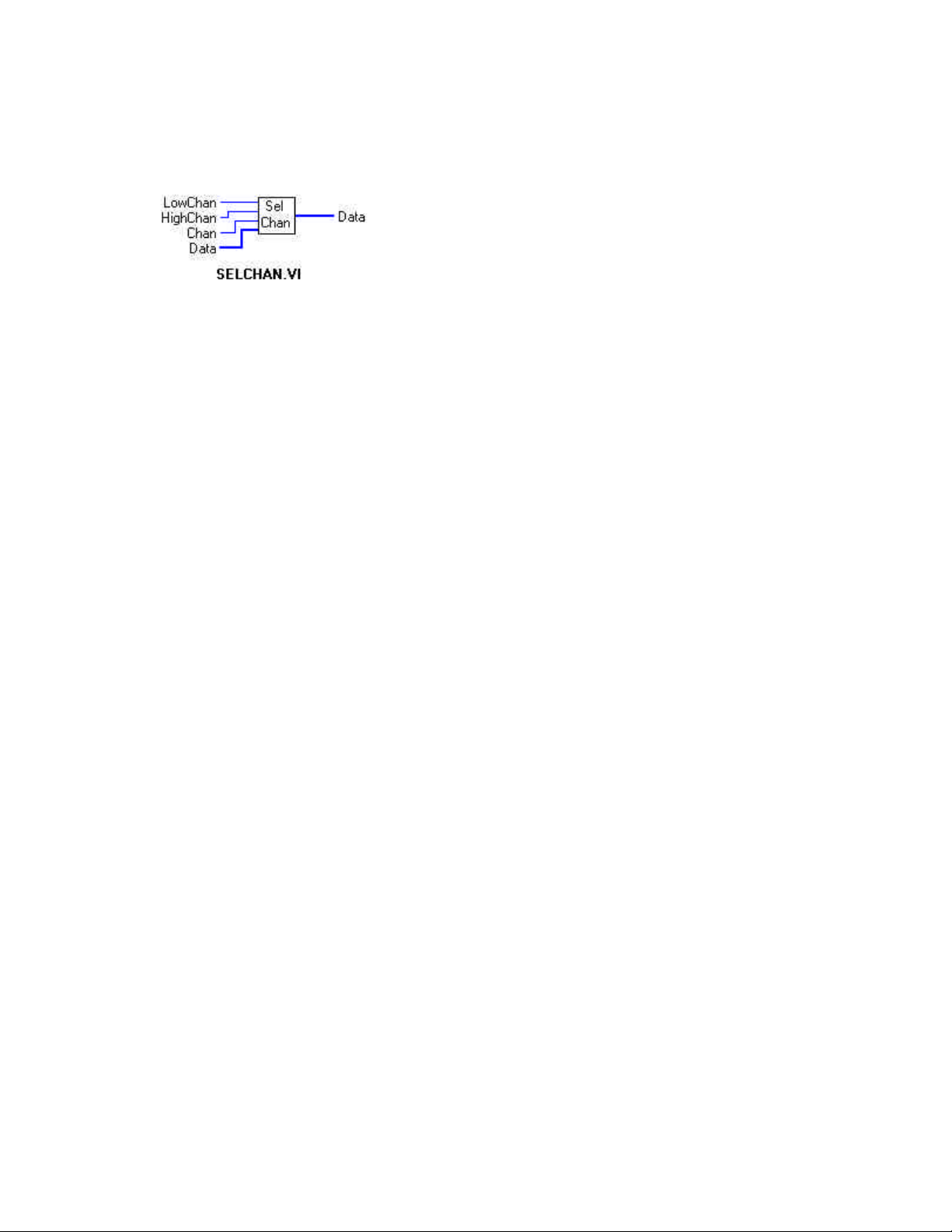
SelChan.VI
Description:
Selects data for one channel from array with interleaved data for several channels.
Summary:
Inputs: LowChan [I32] - Low channel
HighChan [I32] - High channel
Chan [I32] - Channel to view
Data [U16] - Input array
Output: Data [U16] - Output array
Explanation of the Arguments:
LowChan - Low channel of the scan specified in one of the scanning VIs.
HighChan - High channel of the scan specified in one of the scanning VIs.
Chan - The channel having data you wish to view.
Data - Array holding data for all channel
Data(output) - Array holding data for one channel.
NOTE:
See AInScFg.VI for an example of the proper use of this VI.
81
Page 86
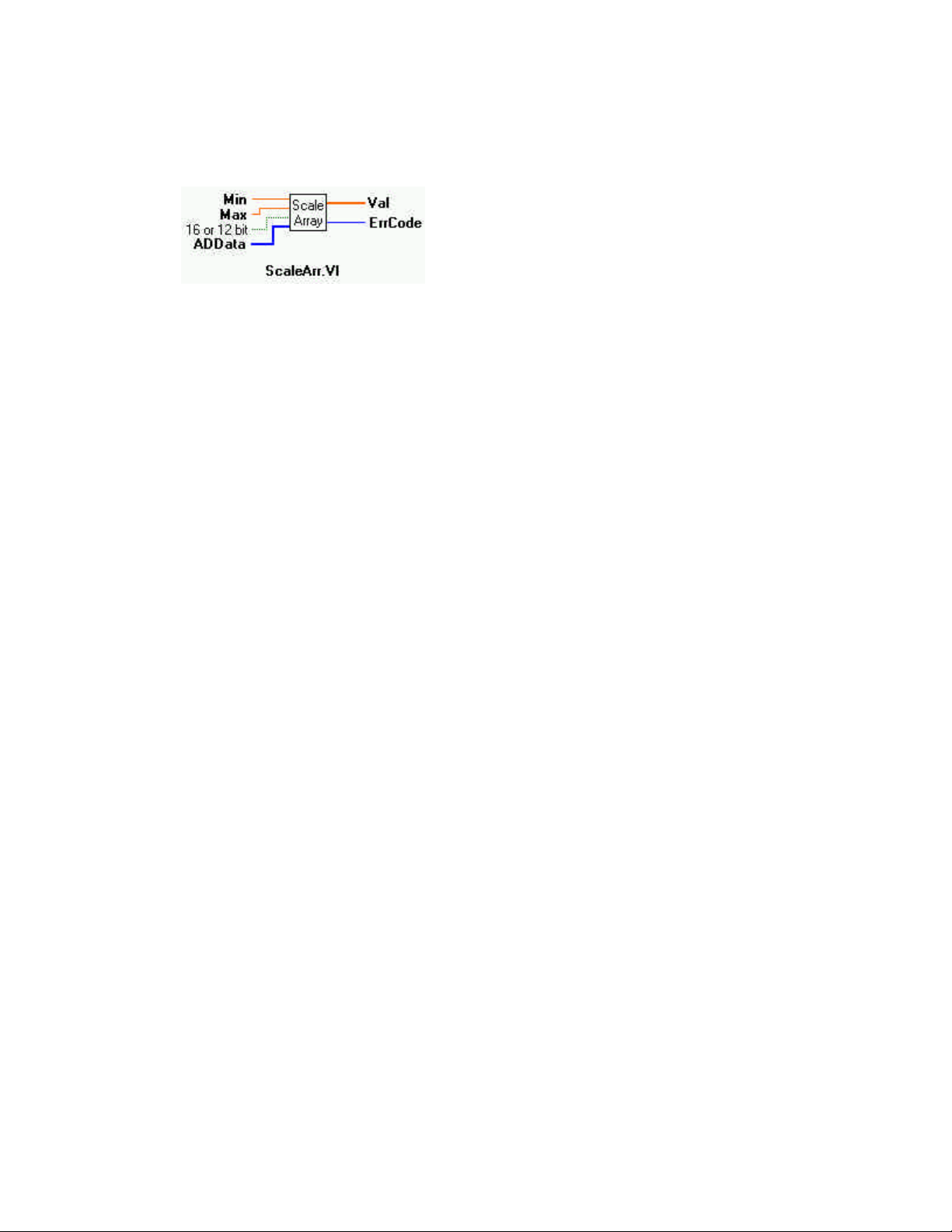
ScaleArr.VI
Description:
Scales raw data from an entire array to a user-specified range.
Summary:
Inputs: Min [SGL] - Lower limit of range
Max [SGL]- Upper limit of range
16 or 12 bits [TF] - Length of raw data; 1 to 16 bits (T), 0 to 12 bits (F = default).
ADData [U16] - Unconverted data array
Output: Val [SGL] - Converted data array
ErrCode [I32] - Error code
Explanation of the Arguments:
Min - Lower limit of selected range.
Max - Upper limit of selected range.
16 or 12 bits - Length of data to be converted. Depends on the type of card being used.
ADData - Array with unconverted raw data.
Val - Array with converted engineering data.
82
Page 87
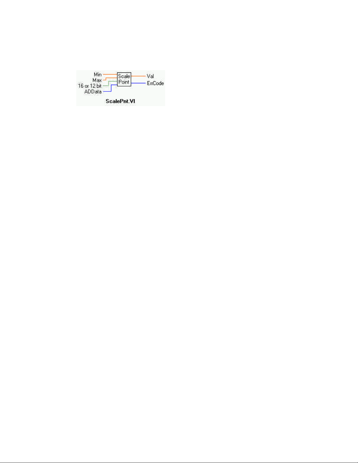
ScalePnt.VI
Description:
Scales raw data point to a user specified range.
Summary:
Inputs: Min [SGL] - Lower limit of range
Max [SGL] - Upper limit of range
16 or 12 bits [TF] - Length of raw data; 1-16 bits (T), or 1 to 12 bits (F = default)
ADData [U16] - Unconverted data array single element.
Output: Val [SGL] - Converted data array element
ErrCode [I32] - Error code
Explanation of the Arguments:
Min - Lower limit of selected range.
Max - Upper limit of selected range.
16 or 12 bits - Length of data to be converted. Depends on the type of card being used.
ADData - Array element with unconverted raw data.
Val - Converted engineering data.
83
Page 88
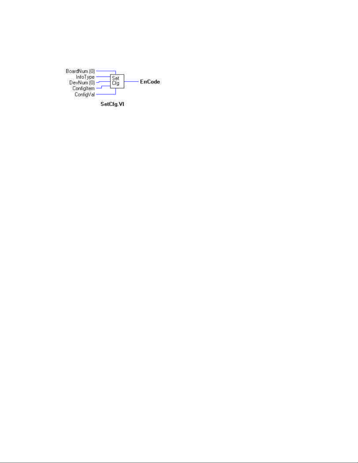
SetCfg.VI
Description:
Sets a configuration option for a board. The configuration information for all boards is stored in the CB.CFG file. All programs that
use the library read this file. This function can be used to override the configuration information stored in the CB.CFG file
Summary:
Arguments: InfoType [I32] - Defines class of configuration information you want to retrieve
BoardNum [U32] - Board number, 0 to 100, when set by InstaCal.
DevNum [I32] - Specifies which device within board
ConfigItem [I32] - Specifies which configuration item
ConfigVal [I32] - New value to set option to
Explanation of the Arguments:
InfoType - The configuration information for each board is grouped into different categories. This argument specifies which category
you want. It should be set to one of the following constants:
GLOBALINFO - Information about the configuration file
BOARDINFO - general information about a board
DIGITALINFO - information about a digital device
COUNTERINFO - information about a counter device
EXPANSIONINFO - information about an expansion device
MISCINFO - One of the miscellaneous options for the board
BoardNum - refers to the board number associated with a board when it was installed.
DevNum - Selects a particular device. If InfoType=DIGITALINFO then DevNum specifies which of the board's digital devices you
want to set information on. If InfoType = COUNTERINFO then DevNum specifies which of the board's counter devices.
ConfigItem - Specifies which configuration item you wish to retrieve. Refer to the table below for a list of all of the possible values
for ConfigItem.
ConfigVal - The value to set the specified configuration item to.
NOTES:
The list of ConfigItem values for each category of configuration information is:
InfoType = GLOBALINFO
GIVERSION - CB.CFG file format
GINUMBOARDS - Number of configured boards
GINUMEXPBOARDS - Number of expansions configured boards
84
Page 89

InfoType = BOARDINFO
BIBASEADR - Base address of board
BIBOARDTYPE - Board Type
BIINTLEVEL - Interrupt level
BIDMACHAN - DMA channel
BIINITIALIZED - TRUE (non-zero) or FALSE (0)
BICLOCK - Clock freq in MHz (1, 4, 6 or 10)
BIRANGE - Selected voltage range
BINUMADCHANS - Number of A/D channels
BIUSESEXPS - Supports expansion boards TRUE/FALSE
BIDINUMDEVS - Number of digital devices
BIDIDEVNUM - Index into digital information for first device
BICINUMDEVS - Number of counter devices
BICIDEVNUM - Index into counter information for first device
BINUMDACHANS - Number of D/A channels
BIWAITSTATE - Setting of Wait State jumper
BINUMIOPORTS - Number of IOPorts used by board
BIPARENTBOARD - Board number of parent board
BIDTBOARD - Board number of connected DT board
InfoType = DIGITALINFO
DIBASEADR - Base address
DIINITIALIZED - TRUE (non-zero) or FALSE (0)
DIDEVTYPE - Device Type - AUXPORT, FIRSTPORTA etc
DIMASK - Bit mask for this port
DIREADWRITE - Read require before write TRUE/FALSE
DICONFIG - Current configuration INPUT or OUTPUT
DINUMBITS - Number of bits in port
DICURVAL - Current value of outputs
InfoType = COUNTERINFO
CIBASEADR - Base address
CIINITIALIZED - TRUE (non-zero) or FALSE (0)
CICTRTYPE - 8254 or 9513 counter, 8536, 7266
CICTRNUM - Which counter on chip
CICONFIGBYTE - Configuration byte
InfoType = EXPANSIONINFO
XIBOARDTYPE - Board type
XIMUXADCHAN1 - A/D channel board is connect to
XIMUXADCHAN2 - 2nd A/D channel board is connected to
XIRANGE1 - Range (gain) of low 16 chans
XIRANGE2 - Range (gain) of high 16 chans
XICJCCHAN - A/D channel that CJC is connected to
XITHERMTYPE - Thermocouple type
XINUMEXPCHANS - Number of expansion channels on board
XIPARENTBOARD - Board number of parent A/D board
85
Page 90
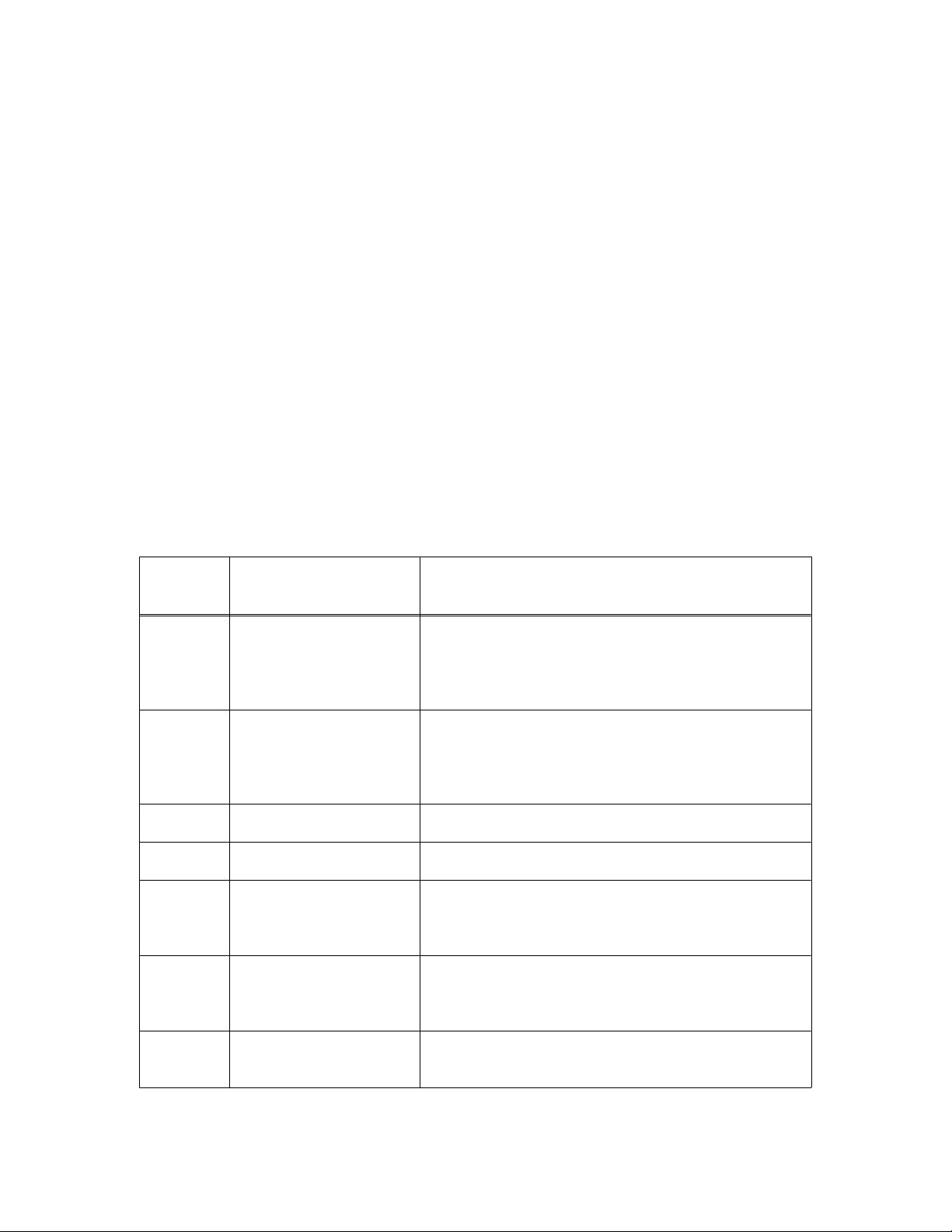
cbSet Trigger()
Description:
This function is used to select the trigger source and setup its parameters. This trigger is used to initiate analog to digital conversions
using the following Universal Library functions.
Ÿ cbAInScan, if the EXTRIGGER option is selected.
Ÿ cbAPretrig
Ÿ cbFilePretrig
Summary: int cbSetTrigger(int BoardNum, int Type, unsigned LowThreshold, unsigned HighThreshold)
Arguments: BoardNum [U32]- board number, 0 to 100, when set by InstaCal.
Type [U32] - trigger type (see table below)
LowThreshold [U32] - low threshold for analog trigger
HighThreshold [U32] - high threshold for analog trigger
ErrCode [I32] - Error code
Parameters
int BoardNum
Specifies the board number associated with the board when it was installed with the configuration program. The board must
have the software selectable triggering source and/or options.
int Type
Specifies the type of triggering based on the external trigger source. This can be one of the constants specified in the column
labeled in the column labeled Type in this table.
GER
SOURCE
EXPLANATIONTYPETRIG-
GATE_NEG_HYSAnalog
GATE_POS_HYSAnalog
GATE_ABOVEAnalog
GATE_BELOWAnalog
TRIG_ABOVEAnalog
TRIG_BELOWAnalog
GATE_IN_WINDOWAnalog
A/D conversions are enabled when the external analog
trigger input is more positive than HighThreshold. A/D
conversions are disabled when the external analog trigger
input more negative than Low/Threshold. Hyster isis is the
level between Low/Threshold and HighThreshold.
A/D conversions are enabled when the external analog
trigger input is more negative than LowThreshold. A/D
conversions are disabled when the external analog trigger
input is more positive than HighThreshold. Hysterisis is
the level between LowThreshold and HighThreshold.
A/D conversions are enabled as long as the external analog
trigger input is more positive than HighThreshold.
A/D conversions are enabled as long as the external analog
trigger input is more negative than LowThreshold.
A/D conversions are enabled when the external analog
trigger makes a transition from below HighThreshold to
above. After conversions are enabled, the external trigger
is ignored.
A/D conversions are enabled when the external analog
trigger input makes a transition from above LowThreshold
to below. After conversions are enabled, the external trigger is ignored.
A/D conversions are enabled as long as the external analog
trigger is inside the region defined by LowThreshold and
HighThreshold.
86
Page 91
GER
SOURCE
EXPLANATIONTYPETRIG-
GATE_OUT_WINDOWAnalog
A/D conversions are enabled as long as the external analog
trigger is outside the region defined by LowThreshold and
HighThreshold.
GATE_HIGHDigital
GATE_LOWDigital
TRIG_HIGHDigital
TRIG_LOWDigital
TRIG_POS_EDGEDigital
TRIG_NEG_EDGEDigital
UNSIGNED LowThreshold
Selects the low threshold used when the trigger input is analog. Must be 0 to 4095 for 12-bit boards and 0 to 65535 for 16-bit
boards. See Note.
This parameter is ignored when the trigger input is digital.
A/D conversions are enabled as long as the external digital
trigger input is 5V (logic HIGH or 1).
A/D conversions are enabled as long as the external digital
trigger input is 0V (logic LOW or 0).
A/D conversions are enabled when the external digital trigger is 5V (logic HIGH or ‘1’). After conversions are
enabled, the external trigger is ignored.
A/D conversions are enabled when the external digital trigger is 0V (logic LOW or ‘0’). After conversions are
enabled, the external trigger is ignored.
A/D conversions are enabled when the external digital trigger makes a transition from 0V to 5V 9 (logic LOW to
HIGH). After conversions are enabled, the external trigger
is ignored.
A/D conversions are enabled when the external digital trigger makes a transition from 5V to 0V (logic HIGH to
LOW). After conversions are enabled, the external trigger
is ignored.
UNSIGNED HighThreshold
Selects the high threshold used when the trigger input is analog. Must be 0 to 4095 for 12-bit boards and 0 to 65535 for 16-bit
boards. See Note.
Returns: int Error Code. Zero if the function is successful. Non-zero if the function fails.
Note: The value of the threshold must be within the range of the analog trigger circuit associated with the board. Please refer to
boards specific information. For example, on the PCI-DAS 1602/16 the analog trigger circuit handles +/-10V. Therefore, a value of
0 corresponds to −10V and 65535 corresponds to +10V
87
Page 92
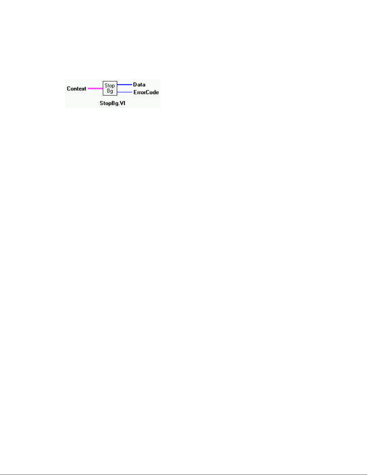
StopBg.VI
Description:
Stops any background operation that is in progress for the specified board. This VI can be used to stop any VI that is running in the
background. It should always be called after any background operation, even when the operation terminates normally.
Summary:
Input: Context [cluster] - Input data structure from a background operation.
Output: Data [U16] - Output array extracted from Context
ErrorCode [I32] - Error code
Explanation of the Arguments:
Context - Data structure containing information from a background operation. Some of the information included is the board
number, the data array, the array size, and the initial status of the background operation.
NOTE:
Wiring of this VI should conform to the following pattern:
Ÿ Start a background operation.
Ÿ GetStat.VI checks for completion (boolean output called "Running").
Ÿ StopBg.VI terminates the operation, if not already done, and frees memory aliases.
Ÿ Data output from the background operation is passed to GetStat.VI and StopBg.VI via "Context", and can be wired from
one or both of them for intermediate or final actions, respectively.
Ÿ The demo VIs illustrate this process effectively.
88
Page 93
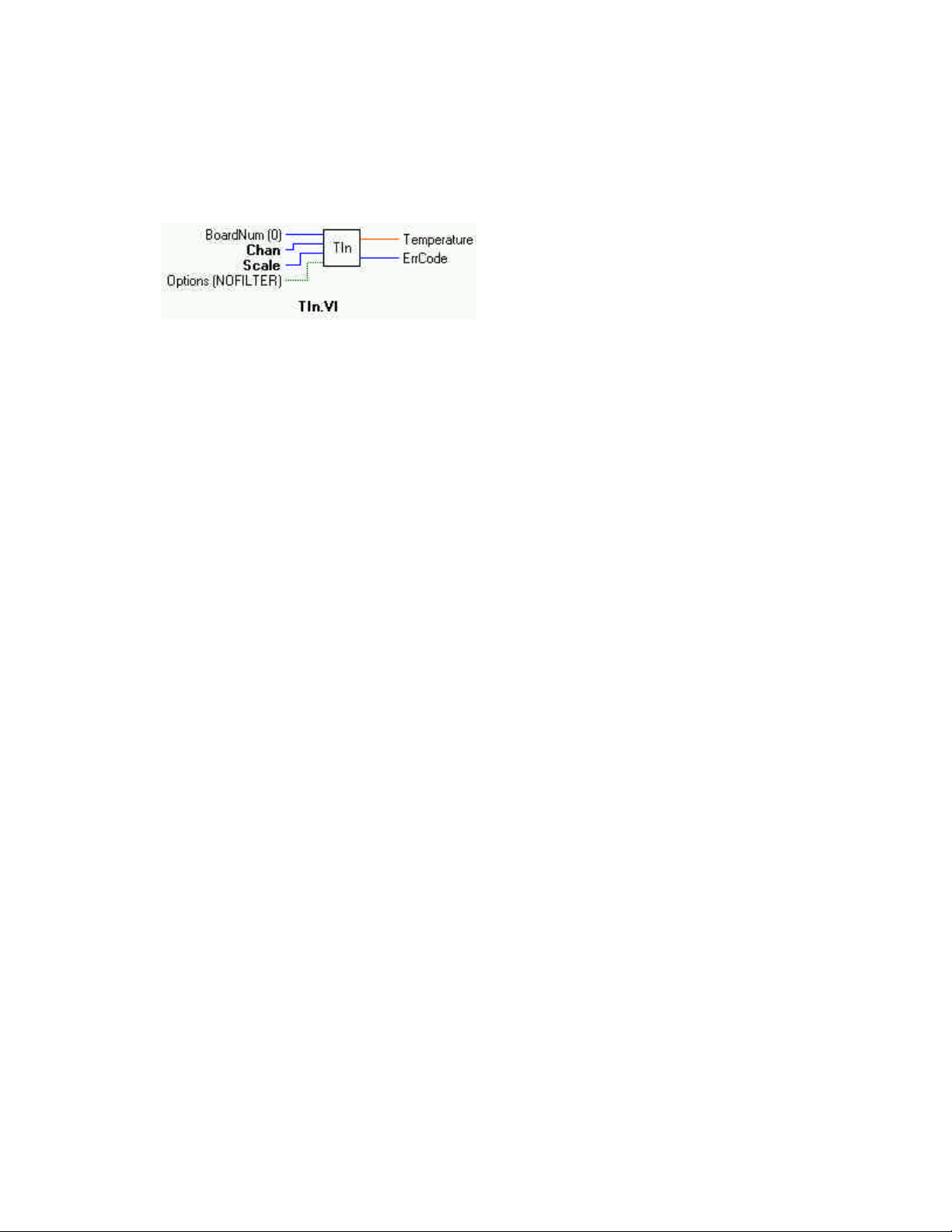
TIn.VI Changed R3.3 ID
Description:
Reads an analog input channel, linearizes it according to selected temperature sensor type, and returns the temperature in degrees.
The CJC channel, the gain, and sensor type, are read from the configuration file. They should be set by running the InstaCal
configuration program.
Summary:
Inputs: BoardNum [U32] - board number, can be 0 to 100 when entered with InstaCal..
Chan [U32] - Channel to read
Scale [U32] - The temperature scale for which to calculate the temperature in degrees.
Options [TF] - Bit that controls data smoothing (averaging) option (T). “NOFILTER” (F) is default.
Outputs: Temperature [SGL] - Temperature returned here
ErrCode [I32] - Error code
Explanation of the Arguments:
Chan - Input channel to read for EXP boards. The channel number is calculated using the following formula:
A/DChan = A/D channel the multiplexer (“mux”) is connected to
MuxChan = Mux board input channel number
Chan = (ADChan+1) * 16 + MuxChan
For example, if you had an EXP16 connected to a CIO-DAS08 via the CIO-DAS08 channel 0 (remember, DAS08 channels are
numbered 0, 1, 2, 3, 4, 5, 6, and 7), AND if you had a thermocouple connected to channel 5 of the EXP16, the value for Chan would
be
(0 + 1) x 16 + 5 = 21.
Scale - Specifies the temperature scale that the input will be converted to. Choices are CELSIUS, FAHRENHEIT and KELVIN.
Temperature - The temperature in degrees is returned here. Thermocouple resolution is approximately 0.25ºC, depending on scale,
range and thermocouple type. RTD resolution is 0.1ºC.
A/D Range - IMPORTANT - If the EXP board is connected to an A/D that does not have programmable gain (DAS08, DAS16,
DAS16F) then the A/D board is read from the configuration file (CB.CFG). In most cases, hardware-selectable ranges should be set
for +/-5V for thermocouples and 0 to 10V for RT Ds. If the board does have programmable gains, the cbTIn() function will set the
appropriate A/D range. See board specific info for details.
Option:
FILTER - The TIn applies a smoothing function to thermocouple readings very much like the electrical smoothing inherent in all
thermocouple instruments. When selected, 10 samples are read from the specified channel and averaged. The average is the reading
returned.
FILTER OFF - If you use the NOFILTER option (F), the thermocouple readings will not be smoothed and you will see a scattering of
readings around a mean. This is the default.
89
Page 94

Note on CJC Channel: The CJC channel is set in the install program. If you have multiple EXP boards, the LabVIEW VI will
apply the CJC reading to the linearization formula in the following manner:
1. If you have chosen a CJC channel for the EXP board that the channel you are reading is on, it will use the CJC temp reading
from that channel.
2. If you have left the CJC channel for the EXP board that the channel you are reading is on to NOT SET, the VI will use the CJC
reading from the next lower EXP board with a CJC channel selected.
For example: Assume you have four CIO-EXP16 boards connected to a CIO-DAS08 on channel 0, 1, 2, and 3, and you have chosen
CIO-EXP16 #1 (connected to CIO-DAS08 channel 0) to have its CJC read on CIO-DAS08 channel 7.
If you have left CIO-EXP16 CJC channels 2, 3, and 4 to NOT SET, those CIO-EXP boards will all use the CJC reading from CIOEXP16 #1, connected to channel 7 for linearization.
As you can see, it is important to keep the CIO-EXP boards in the same case and out of any breezes to ensure valid CJC readings.
90
Page 95
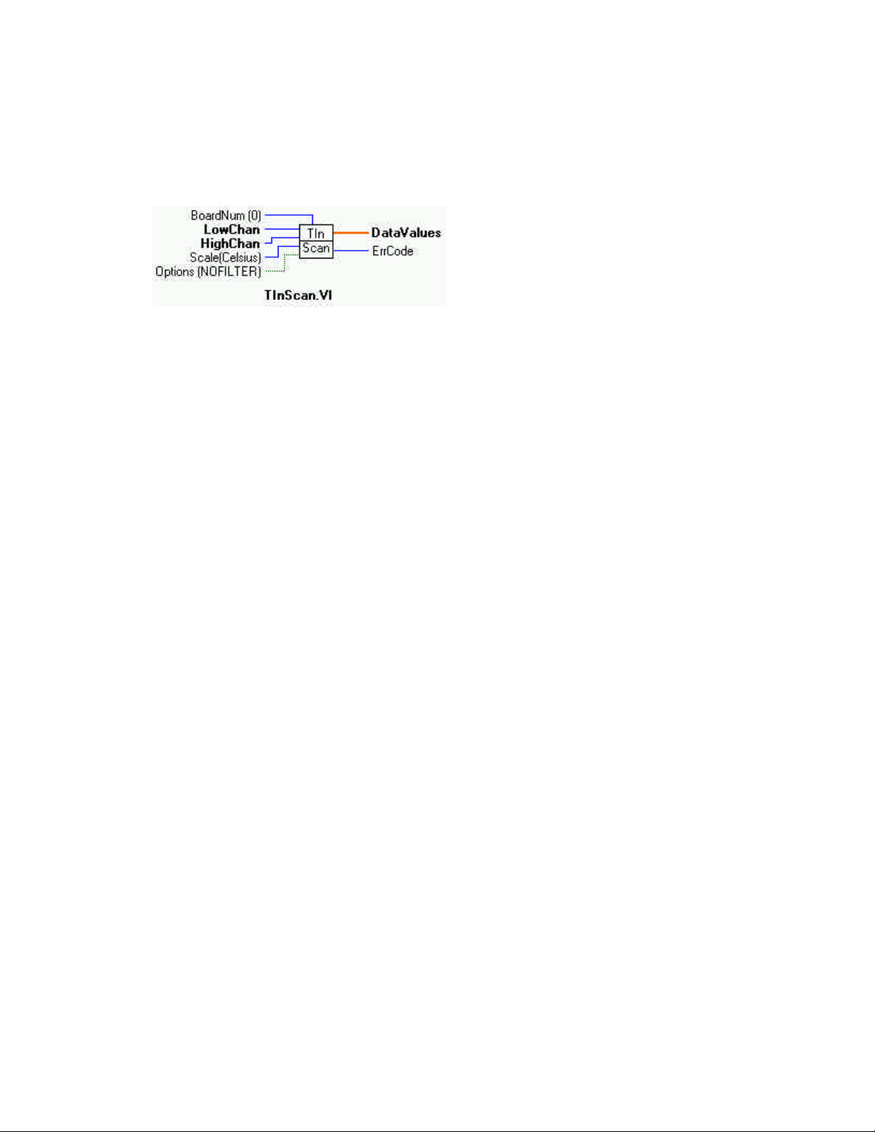
TInScan.VI Changed R3.3 ID
Description:
Reads a range of channels from an analog input board, linearizes them according to temperature sensor type, and returns the temperatures to an array in degrees. The CJC channel, the gain, and sensor type are read from the configuration file. Use InstaCal to
change any of these options.
Summary:
Inputs: BoardNum [U32] - board number, can be 0 to 100 when entered with InstaCal.
LowChan {U32] - Low mux channel of scan
HighChan [U32] - High mux channel of scan
Scale [U32] - CELSIUS, FAHRENHEIT or KELVIN
Options [TF] -Bit that controls data smoothing (averaging) option (T). “NOFILTER” (F) is default
Outputs: DataValues [SGL] - Temperature returned here
ErrCode [I32] - Error code
Explanation of the Arguments:
BoardNum - refers to the board number associated with a board when it was installed.
Low / High Channel # - Specify the range of multiplexer channels that will be scanned. For EXP boards, these channel numbers are
calculated using the following formula:
A/DChan = A/D channel that mux is connected to
MuxChan = Mux board input channel number
Chan = (ADChan+1) * 16 + MuxChan (where MuxChan ranges from 0 to 15, indicating which channel on a particular
board)
For example, if you had an EXP16 connected to a CIO-DAS08 via the CIO-DAS08 channel 0 (remember, DAS08 channels are
numbered 0, 1, 2, 3, 4, 5, 6, and 7), AND if you had a thermocouple connected to channel 5 of the EXP16, the value for Chan would
be
(0 + 1) x 16 + 5 = 21. For 6 and 7 of the EXP16, the value for LowChan would be (0 + 1) x 16 + 5 = 21 and the value for HighChan
would be (0 + 1) x 16 + 7 = 23
Scale - Specifies the temperature scale that the input will be converted to. Choices are CELSIUS, FAHRENHEIT and KELVIN.
DataValues[] - The temperature is returned in degrees. Each element in the array corresponds to a channel in the scan. DataBuffer
must be at least large enough to hold HighChan - LowChan + 1 temperature values.
Options:
FILTER (T) - The TIn applies a smoothing function to thermocouple readings very much like the electrical smoothing inherent in
all
thermocouple instruments. When selected, 10 samples are read and averaged on each channel. The average is the reading returned.
NOFILTER (F) - If you use the NOFILTER option then the thermocouple will readings will not be smoothed and you will see a scattering of readings around an mean. This is the default.
91
Page 96

Range - IMPORTANT - If the EXP board is connected to an A/D that does not have programmable gain (DAS08, DAS16,
DAS16F), then the A/D board range is read from the configuration file (cb.cfg). In most cases, hardware-selectable ranges should be
set to +/-5V for thermocouples and 0 to 10V for RTDs. If the board does have programmable gain, the TInScan VI will set the
appropriate A/D range.
Note on CJC Channel: The CJC channel is set in the install program. If you have multiple EXP boards, the LabVIEW VI will
apply the CJC reading to the linearization formula in the following manner:
1. If you have chosen a CJC channel for the EXP board that the channel you are reading is on, it will use the CJC temp reading
from that channel.
2. If you have left the CJC channel for the EXP board that the channel you are reading is on to NOT SET, the VI will use the CJC
reading from the next lower EXP board with a CJC channel selected.
For example: Assume you have four CIO-EXP16 boards connected to a CIO-DAS08 on channel 0, 1, 2, and 3, and you have chosen
CIO-EXP16 #1 (connected to CIO-DAS08 channel 0) to have its CJC read on CIO-DAS08 channel 7.
If you have left CIO-EXP16 CJC channels 2, 3, and 4 to NOT SET, those CIO-EXP boards will all use the CJC reading from CIOEXP16 #1, connected to channel 7 for linearization.
As you can see, it is important to keep the CIO-EXP boards in the same case and out of any breezes to ensure valid CJC readings.
IMPORTANT NOTE
In order to understand the functions, you must read the Board-Specific Information section found in the Universal
Library user's guide. The example programs should be examined and run before attempting any programming of
your own.
92
Page 97

For Your Notes.
93
 Loading...