

Page 1
Circulation Heaters
CHF Series
Self-contained heating units designed for optimum
operating efficiency and performance—
Providing trouble-free service and application flexibility!
All of the heat generated by the elements is immediately
transferred to the medium being processed with minimal losses.
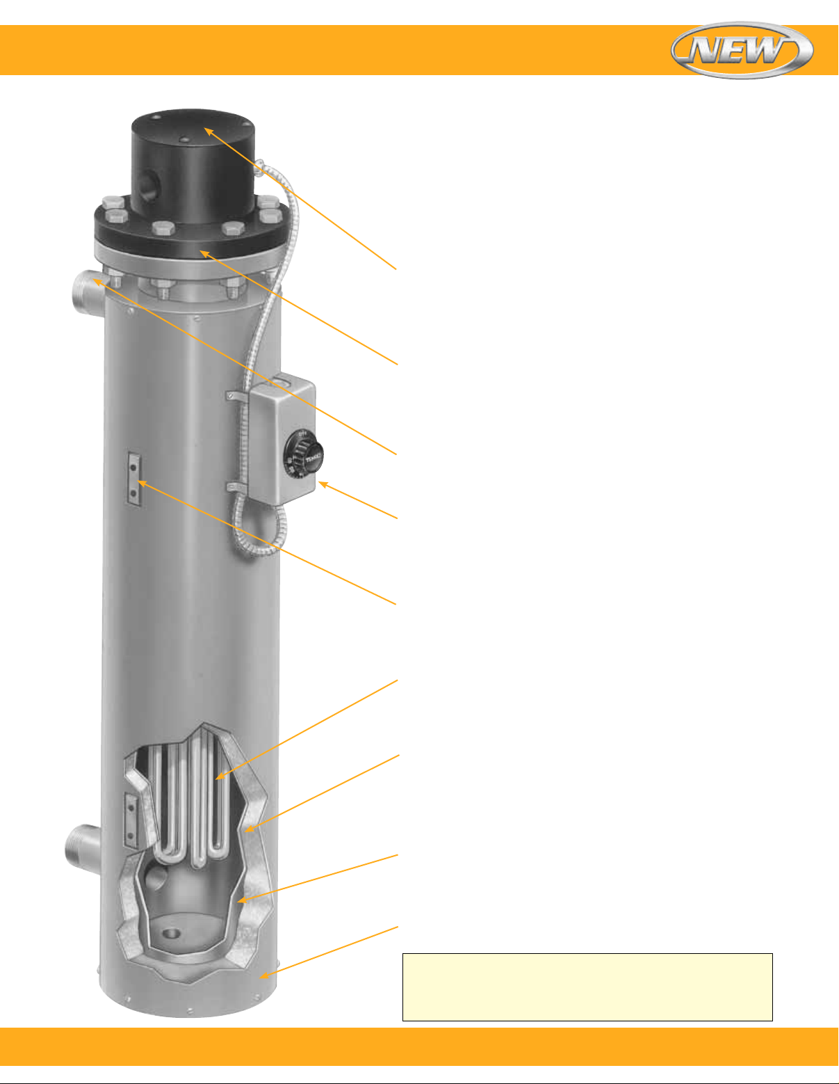
Standard and optional features include…
General purpose (NEMA 1) terminal housing is standard. Moisture
proof (NEMA 4) and/or explosion resistant (NEMA 7) housings are
optional. A set of installation and maintenance instructions along
with a wiring diagram can be found inside the terminal housing of
each unit.
Heating source—32 and 64 mm (11⁄4" and 21⁄2") screw plug heaters
are used on smaller units. 76 to 356 mm (3 to 14") size heaters
use flanged immersion heaters. The flanges are made from forged
steel rated for 150 lbs with raised face. Supplied with threaded
eyebolts for ease of handling and installation. Optional stainless
steel flanges or 300 lb ratings available.
Inlet-outlet connections are NPT pipe threads for 76 to 203 mm
(3 to 8") circulation heaters (flanges are optional). Standard inletoutlet connections on 254 mm (10") and larger units are 150 lb
rated flanges.
Optional feature double-pole non-indicating bulb and capillary
type thermostat can be located in the terminal box (standard)
or attached to the insulation jacket as pictured. Solid state
temperature controllers and indicating thermostats are available.
Over-temperature protection can be provided by attaching a
thermocouple to one of the elements.
Threaded mounting lugs to support the unit are welded to the steel
vessel. Custom supports can be designed to fit your structure.
Wide selection of heating element sheath materials for maximum
corrosion resistance to the medium being processed. On smaller
circulation units with screw plug heaters, the element diameter is
8 or 12 mm (0.315 or 0.475"). On larger units with flanged heaters,
the element diameter is 12 mm (0.475").
The vessel is surrounded with 25 mm (1") thick insulation rated
to 399°C (750°F) to minimize heat loss. Additional insulation or a
high temperature ceramic fiber insulation is optional. Vessels can
also be supplied uninsulated.
Vessel material is SA53B or SA106B steel. Good for up to
399°C (750°F) operating temperature. For drainage and cleaning
purposes, a drain plug is located in the base of the tank.
Optional: stainless steel vessel.
Outer stainless steel sheet metal jacket protects the insulation
from the environment and keeps it dry. Optional: Stainless steel
outer jacket with a weather-tight seal.
Note: Branch Circuit Wiring—Flange heater elements are wired
into branch circuits having a maximum current of 48 Amps.
The number of circuits is listed next to the heater’s voltage
and phase in the To Order tables. For different circuit wiring
configurations, consult Omega.
To order, call 1-800-826-6342 or shop online at omega.com
SM
1
Page 2

Circulation Heaters
Checklist for Selecting the Proper Circulation Heater
U Determine a Safe and Efficient Element Watt Density
Element Watt Density is the wattage dissipated per square inch of the
element sheath surface and is calculated with the following formula:
element wattage
Watt Density =
π × element diameter × element heated length
For a particular application, element watt density will govern element sheath
temperature. Factors to consider when choosing a suitable watt density are:
1. Many materials are heat sensitive and can decompose or
be damaged if the element is running too hot.
2. Air and other gases that are poor conductors of heat require
watt densities matched to the velocity of the gas flow to
prevent element overheating.
3. Mineral deposits when heating hard water and cleaning
solutions can build up on the element sheath, acting as a
heat insulator and raising the internal element temperature.
If these deposits cannot be periodically removed, use
a lower watt density element to increase heater life
expectancy.
U Select the Element Sheath Material
Sheath Material Selection
CORROSION. In addition to selecting a sheath material that is compatible with the
heated medium, other factors that affect corrosion need to be considered:
1. The temperature of the corrodent—As temperature
increases the degree of corrosion increases. Also
3. Velocity of the corrodent—Increased velocity can
increase the corrosion rate.
remember that usually the element temperature is higher
than the material it is heating.
2. The degree of aeration to which a corrodent is exposed—
Stagnant conditions can deprive the stainless steels of
oxygen, which is required to maintain their corrosion
resistant surface.
Standard Element Sheath Materials
Incoloy
®
800 — A Nickel (30 to 35%), Chromium
(19 to 23%), Iron alloy. The high nickel content of this alloy
contributes to its resistance to scaling and corrosion. Used
in air heating (also see Incoloy
of potable water and other liquids that are not corrosive to an
®
Incoloy
800 sheath.
®
840) and immersion heating
Low Carbon Steel — Applications include fluid heat transfer
media, tar, high to low viscosity petroleum oils, asphalt,
wax, molten salt, and other solutions not corrosive to a steel
sheath.
316 Stainless Steel — A Chromium (16 to 18%), Nickel
(11 to 14%), Iron Alloy with Molybdenum (2 to 3%) added
to improve corrosion resistance in certain environments,
especially those that would tend to cause pitting due to the
presence of chlorides. Applications include deionized water.
Copper — Mainly used in clean water heating for
washrooms, showers, rinse tanks and freeze protection
of storage tanks.
Optional Element Sheath Materials
304 Stainless Steel — A Chromium (18 to 20%), Nickel
(8 to 11%), Iron Alloy used in the food industry, sterilizing
solutions, air heating and many organic and inorganic
chemicals.
321 Stainless Steel — A Chromium (17 to 20%), Nickel
(9 to 13%), Iron Alloy modified with the addition of titanium
to prevent carbide precipitation and the resulting
intergranular corrosion that can take place in certain
mediums when operating in the 427 to 649°C
(800 to 1200°F) temperature range.
Incoloy
®
840 — A Nickel (18 to 20%), Chromium
(18 to 22%), Iron alloy. Incoloy 840 has about 10%
less nickel than Incoloy 800. Used in many air heating
applications where it has exhibited superior oxidation
resistance at less cost than Incoloy 800.
Incoloy
®
825 — A Nickel (38 to 46%), Chromium
(19.5 to 23.5%), Molybdenum (2 to 3%) Iron alloy.
Consult Omega for more information.
Surface Treatments for Stainless Steel and Incoloy® Elements and Other Wetted Parts to Improve Corrosion Resistance
Flanged immersion heater surfaces in contact with the material being heated can be passivated or electro-polished to improve
their resistance to corrosion.
Passivation removes surface contamination, usually iron, so that the optimum corrosion resistance of the stainless steel
is maintained. Surface contamination would come from the small amount of steel that may be worn off a tool during the
manufacturing process. Passivating is accomplished by dipping the heater in a warm solution of nitric acid.
Electro-Polishing is an electrochemical process that removes surface imperfections and contaminants, enhancing the corrosion
resisting ability of the stainless steels. The resultant surface is clean, smooth and bright. Many medical and food applications
require this finish.
2
To order, call 1-800-826-6342 or shop online at omega.com
SM
Page 3
Circulation Heaters
U Standard Terminal Housings
Omega circulation heaters are supplied with a General Purpose Housing (NEMA 1) as standard
unless otherwise specified.
Additional housing types include:
Moisture Resistant (NEMA 4)
Explosion Resistant (NEMA 7)
Moisture/Explosion Resistant (NEMA 4/7)
Explosion resistant terminal housings are intended to provide
containment of an explosion in the enclosure only. No portion of
the heater assembly outside the enclosure is covered under this
NEMA rating. Abnormal use of a heater which results in excessive
temperature can create hazardous conditions such as a fire. Never
perform any type of service nor remove the housing cover prior to
disconnecting all electrical power to the heater.
Optional Terminal Housing Standoff Construction
The electrical housing is separated from the flange by an air gap
(six-inch standard) to lower the ambient temperature of the electrical
wiring. This option is used on flanged immersion heaters where the
flange temperature exceeds 250°C (482°F).
Temperature Control
Thermostats
Thermostats are an optional feature on flanged immersion
heaters. This type of control operates by expansion and
contraction of a liquid in response to temperature change.
Liquid contained within the sensing bulb and capillary flexes
a diaphragm, causing the opening and closing of a snap
action switch. For heating applications the contacts are
normally closed and open on temperature rise.
Installation Warnings and Recommendations
1. Do not use the thermostat as a power switch. Use some
other means of disconnecting power to the heater for
servicing.
2. A Thermostat is not a fail-safe device. Use an approved
high temperature limit control and/or pressure limit control
for safe operation.
3. Avoid kinking or bending the capillary tube too sharply as
this will alter the calibration and/or render the thermostat
inoperable.
4. Excess capillary tube should be coiled neatly in junction
box.
5. The capillary tube must never touch the thermostat
contacts as this will create an electrical short capable of
harming personnel and/or equipment.
Optional Circulation Heater Features
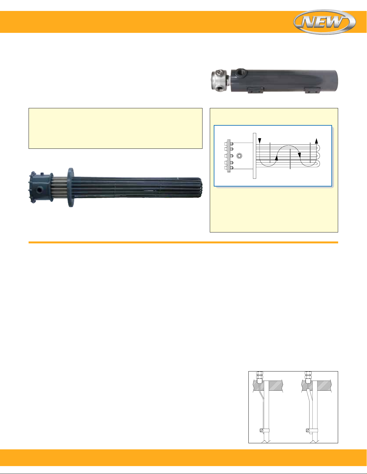
Flow Control Baffles
Used on circulation tank heaters to aid heat
transfer by forcing the liquid or gas back and
forth across the elements. Baffles can be custom
designed and positioned for your application.
Thermocouples
Type J or Type K thermocouples can be supplied for process
temperature or over-temperature control. Type J is reliable
and accurate for temperatures up to 538°C (1000°F). Type K
should be used for higher temperatures.
For measuring process temperatures the thermocouple can
be mounted in a thermowell in the center of the element
bundle. Note that a location somewhere away from the
heater may give a more accurate measurement of process
temperature.
For over-temperature protection the thermocouple is usually
attached to one of the elements (Figure A) and any unusual
rise in element temperature would shut the heater down.
This thermocouple may also be mounted in a thermowell
(Figure B), which is then attached to one of the heating
elements if desired. This protects the thermocouple from the
solution being heated and allows you to replace it without
removing the heater, but does increase its response time.
Temperature and
over-temperature
controls for using
the signal generated
by thermocouples
and how to select
the best control for
your application can
be found at
omega.com/
controllers
Fig. A Fig. B
To order, call 1-800-826-6342 or shop online at omega.com
SM
3
Page 4
Circulation Heaters
Circulation Heater Installation Recommendations
Omega circulation heaters will have a long life and provide dependable, trouble-free service if properly
installed, operated and maintained as per the following recommendations:
Installation
1. Flange heaters are supplied with two drilled and tapped
holes for threaded eye bolts, providing ease of handling
during installation and flange removal during maintenance
cleaning or heater replacement.
2. Replacement of heater is inevitable. Therefore, provide
adequate space for installation, allowing ample room to
remove the flange heater for cleaning or replacement.
3. In applications requiring the circulation heater to be fed by
an inline pump, install the pump at the inlet end.
4. To maintain the lowest possible temperature at the
terminal box, place the outlet at the end opposite to the
terminal box. If your process temperature is circulating
at 232°C (450°F) or above (at the nozzle closest to
the flange), stand-off terminal box construction is
recommended.
5. To prevent temperature and/or pressure buildup on closed
loop circulation heater systems, adequate and strategically
located thermocouples for temperature controllers and
pressure relief valves should be installed. Never over-rate
pressure relief valves beyond the pressure temperature
rating of the flange being used.
6. During the process cycle, flow rate of the medium being
heated should never be interrupted or reduced, thus
creating an overheating condition. Excess temperature
can result in damage to the medium being processed and
premature heater failure.
7. Make sure that your circulation heater is equipped with
the proper terminal housing for the environment in which
the heater is being used. NEMA 1—general purpose,
NEMA 4—moisture resistant, and NEMA 7—
explosion resistant.
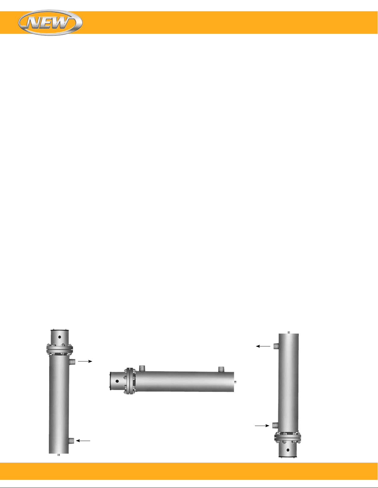
Vertical Mounting—Liquids:
With terminal housing up
and inlet pipe on the bottom,
the heating elements will
be immersed at all times to
prevent premature failure.
Wiring
1. All heater installations must be properly earth grounded to
eliminate electric shock hazard. Electrical wiring must be in
accordance with Local and/or National Electrical Codes.
2. Circulation heaters are supplied standard with NEMA
1 terminal housings. All power to heaters must be
disconnected before removing the terminal housing cover
and performing any type of service.
3. Electrical connections on heater terminals must be kept
tight. Loose connections will create arcing, over-heating,
and eventually will destroy the heater terminal and cause
premature heater failure.
4. If the amperage rating of your circulation heater exceeds
the amperage capacity of the supplied thermostat, mercury
relays or magnetic contactors should be used with the
thermostat.
5. Over-temperature protection thermocouples require a
separate conduit to the control panel for the thermocouple
wire.
6. Omega offers a large selection of power control panels for
circulation heaters. See omega.com/controllers
Maintenance
1. Never perform any type of service on the unit prior to
disconnecting all electrical power and shutting off all
intake lines.
2. Remove sludge deposits through the drain plug.
3. Check flange bolts for tightness.
4. Check terminal connections for tightness.
5. Check thermocouple or thermostat bulb for response to
temperature changes. If defective, replace immediately.
6. Check for leaks.
7. Depending on operating conditions and medium being
processed, the flange or screw plug heater should be
periodically removed for physical inspection and cleaning
of the element bundle.
4
Vertical Mounting—
Gases: Mount
with terminal
enclosure and inlet
Horizontal Mounting—Liquids and Gases:
Always mount heater with inlet-outlet pipes
facing up to ensure the heating elements will
be immersed at all times to prevent premature
failure. For liquid heating, outlet may be at
either end. When heating gases the inlet
should be closest to the terminal enclosure to
minimize terminal box wiring temperatures.
pipe at bottom of
tank to minimize
terminal box wiring
temperatures.
To order, call 1-800-826-6342 or shop online at omega.com
SM
Page 5
Circulation Heaters
Circulation Tank Assembly Maximum Immersed Element Length
Standard circulation heaters shown in the tables have
element immersion lengths determined by the element
wattage and element watt density. The screw plug or flange
heater containing the elements is matched to a standard
circulation heater tank assembly to assure proper heat
transfer and heated material flow. When designing a system
Dimension Maximum Immersed
Nominal Drawing Element Length
Pipe Size Number inch mm
11⁄4 NPT 1.1 18.0 457
1.2 26.0 660
21⁄2 NPT 2.1 25.5 648
2.2 35.5 902
2.3 48.0 1219
3" Flange 3.1 28.0 711
3.2 38.0 965
3.3 50.5 1283
4" Flange 4.1 26.5 673
4.2 37.0 940
4.3 58.0 1473
4.4 79.0 2007
5" Flange 5.1 36.0 914
5.2 43.0 1092
5.3 54.5 1384
5.4 68.0 1727
5.5 85.0 2159
6" Flange 6.1 26.5 673
6.2 37.0 940
6.3 58.0 1473
6.4 79.0 2007
8 watts/in2 (1.3 watts/cm2) — Typical Applications: Fuel Oils (Bunker C and Number 6)
l Steel Screw Plug and Steel 150 lb Flanged Heater Sizes l Steel Sheath Heating Elements
l Steel Tank l NEMA 1 Terminal Housing
with a heater not shown on these pages the table below
can be used to select a tank size based on the calculated
immersion length. If a standard tank size is not suitable
for your installation, Omega will design and manufacture a
custom tank and heater assembly to satisfy the requirements
of your application.
Dimension Maximum Immersed
Nominal Drawing Element Length
Pipe Size Number inch mm
8" Flange 8.1 32.5 826
8.2 40.5 1029
8.3 47.5 1207
8.4 55.0 1397
8.5 64.5 1638
8.6 73.5 1867
8.7 83.5 2121
10" Flange 10.1 60.0 1524
10.2 67.0 1702
10.3 73.0 1854
10.4 82.0 2083
10.5 90.0 2286
12" Flange 12.1 59.0 1499
12.2 66.5 1689
12.3 74.0 1880
12.4 81.5 2070
12.5 89.0 2261
14" Flange 14.1 58.0 1473
14.2 65.5 1664
14.3 73.0 1854
14.4 80.5 2045
14.5 88.0 2235
Note: 3-Phase only. Cannot be rewired for single phase.
Nominal
Pipe
Size
1
⁄2 NPT
2
3 elements
3"—150 lb
3 elements
(C*) = Number of Branch Circuits per heater
Drawing
Number inch mm inch mm inch mm
2.2 4211⁄16 1084 321⁄2 826 261⁄2 673
2.3 553⁄16 1402 45 1143 39 991
Dimensional
Drawing
Number
KW
120V 240V-1Ph (C*) 240V-3Ph (C*) 480V-1Ph (C*) 480V-3Ph (C*) lb kg
2.2 2 — — CHF01100 (1) — CHF01101 (1) 37 17
2.3 3 — — CHF01102 (1) — CHF01101 (1) 46 21
3.2 2 — — CHF01104 (1) — CHF01105 (1) 62 28
3.3 3 — — CHF01106 (1) — CHF01107 (1) 76 34
Drawing
2
“A” “B” “C”
Model Number
Drawing
3
Drawing “A” “B” “C”
Number inch mm inch mm inch mm
3.2 445⁄8 1133 321⁄2 826 261⁄2 673
3.3 571⁄8 1451 45 1143 39 991
Approx Weight
To order, call 1-800-826-6342 or shop online at omega.com
SM
5
Page 6
Circulation Heaters
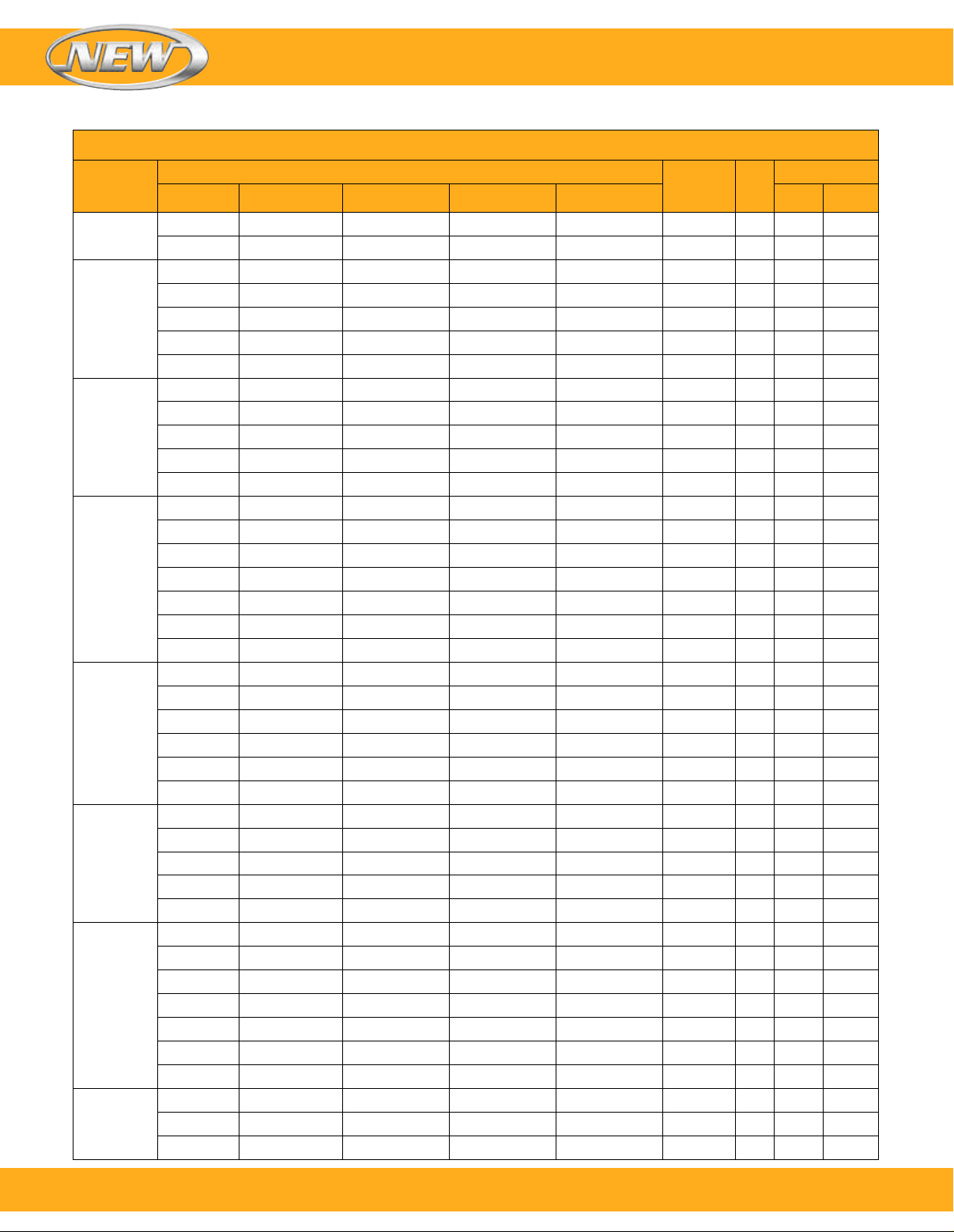
23 watts/in2 (3.6 watts/cm2)—Typical Applications: Lightweight Oils, Degreasing Solutions, Heat Transfer Oils
To Order Visit omega.com/chf2 for Pricing and Details
Nominal
Pipe
Size
1
⁄4 NPT
1
2 elements
1
⁄2 NPT
2
3 elements
3"—150 lb
3 elements
4"—150 lb
6 elements
5"—150 lb
6 elements
5"—150 lb
9 elements
6"—150 lb
12
elements
6"—150 lb
15
elements
(continued)
120V
CHF01186 CHF01187 (1) — — —
CHF01188 CHF01189 (1) — — —
— CHF01190 (1) CHF01191 (1) CHF01192 (1) CHF01193 (1)
— CHF01194 (1) CHF01195 (1) CHF01196 (1) CHF01197 (1)
— CHF01198 (1) CHF01199 (1) CHF01200 (1) CHF01201 (1)
— CHF01202 (1) CHF01203 (1) CHF01204 (1) CHF01205 (1)
— CHF01206 (1) CHF01207 (1) CHF01208 (1) CHF01209 (1)
— CHF01210 (1) CHF01211 (1) CHF01212 (1) CHF01213 (1)
— CHF01214 (1) CHF01215 (1) CHF01216 (1) CHF01217 (1)
— CHF01218 (1) CHF01219 (1) CHF01220 (1) CHF01221 (1)
— CHF01222 (1) CHF01223 (1) CHF01224 (1) CHF01225 (1)
— CHF01226 (1) CHF01227 (1) CHF01228 (1) CHF01229 (1)
— CHF01230 (1) CHF01231 (1) CHF01232 (1) CHF01233 (1)
— CHF01234 (1) CHF01235 (1) CHF01236 (1) CHF01237 (1)
— CHF01238 (2) CHF01239 (1) CHF01240 (1) CHF01241 (1)
— CHF01242 (2) CHF01243 (1) CHF01244 (1) CHF01245 (1)
— CHF01246 (2) CHF01247 (1) CHF01248 (1) CHF01249 (1)
— — CHF01250 (2) CHF01251 (2) CHF01252 (1)
— — CHF01253 (2) CHF01254 (2) CHF01255 (1)
— CHF01256 (2) CHF01257 (1) CHF01258 (1) CHF01259 (1)
— CHF01260 (2) CHF01261 (1) CHF01262 (1) CHF01263 (1)
— CHF01264 (2) CHF01265 (1) CHF01266 (1) CHF01267 (1)
— CHF01268 (2) CHF01269 (1) CHF01270 (1) CHF01271 (1)
— — CHF01272 (2) CHF01273 (2) CHF01274 (1)
— — CHF01275 (2) CHF01276 (2) CHF01277 (1)
— CHF01278 (3) CHF01279 (1) CHF01280 (1) CHF01281 (1)
— CHF01282 (3) CHF01283 (3) CHF01284 (1) CHF01285 (1)
— CHF01286 (3) CHF01287 (3) CHF01288 (3) CHF01289 (1)
— — CHF01290 (3) CHF01291 (3) CHF01292 (1)
— — CHF01293 (3) CHF01294 (3) CHF01295 (3)
— CHF01296 (1) CHF01297 (1) CHF01298 (1) CHF01299 (1)
— CHF01300 (2) CHF01301 (1) CHF01302 (1) CHF01303 (1)
— CHF01304 (2) CHF01305 (2) CHF01306 (1) CHF01307 (1)
— CHF01308 (2) CHF01309 (2) CHF01310 (2) CHF01311 (1)
— CHF01312 (3) CHF01313 (2) CHF01314 (2) CHF01315 (1)
— — CHF01316 (4) CHF01317 (3) CHF01318 (2)
— — CHF01319 (4) CHF01320 (3) CHF01321 (2)
— CHF01322 (3) CHF01323 (1) CHF01324 (1) CHF01325 (1)
— CHF01326 (3) CHF01327 (5) CHF01328 (1) CHF01329 (1)
— CHF01330 (3) CHF01331 (5) CHF01332 (3) CHF01333 (1)
240V-1Ph (C*)
Model Number Dim
240V-3Ph (C*) 480V-1Ph (C*) 480V-3Ph (C*) lb kg
Drawing
Number KW
1.1 1.5 14 6
1.2 2 18 8
2.1 3 28 13
2.1 4.5 29 13
2.2 6 37 17
2.3 7.5 45 20
2.3 9 46 21
3.1 3 53 24
3.1 4.5 54 24
3.2 6 62 28
3.3 7.5 74 34
3.3 9 76 34
4.1 6 78 35
4.1 9 91 41
4.2 12 94 43
4.3 15 117 53
4.3 18 120 54
4.4 25 147 67
4.4 30 151 68
5.2 12 126 57
5.2 15 128 58
5.3 18 146 66
5.3 20 147 67
5.4 25 172 78
5.5 30 192 87
5.2 18 132 60
5.2 23 135 61
5.3 27 154 70
5.4 38 183 83
5.5 45 205 93
6.1 12 127 58
6.2 18 152 69
6.2 24 157 71
6.3 30 197 89
6.3 36 202 92
6.4 50 249 113
6.4 60 257 117
6.1 15 130 59
6.2 23 156
6.2 30 163 74
Approx Weight
71
6
To order, call 1-800-826-6342 or shop online at omega.com
SM
Page 7
Circulation Heaters
Nominal
Model Number Dim
Pipe
Size
6"—150 lb
15
elements
120V
240V-1Ph (C*)
240V-3Ph (C*) 480V-1Ph (C*) 480V-3Ph (C*) lb kg
— CHF01334 (5) CHF01335 (5) CHF01336 (3) CHF01337 (1)
— CHF01338 (5) CHF01339 (5) CHF01340 (3) CHF01341 (5)
— — CHF01342 (5) CHF01343 (3) CHF01344 (5)
— — CHF01345 (5) CHF01346 (5) CHF01347 (5)
8"—150 lb
18
elements
— CHF01348 (3) CHF01349 (2) CHF01350 (2) CHF01351 (1)
— — CHF01352 (2) CHF01353 (2) CHF01354 (1)
— — CHF01355 (3) CHF01356 (3) CHF01357 (2)
— — CHF01358 (3) CHF01359 (3) CHF01360 (2)
— — CHF01361 (6) CHF01362 (3) CHF01363 (2)
— — CHF01364 (6) — CHF01365 (2)
8"—150 lb
24
elements
— CHF01366 (4) CHF01367 (2) CHF01368 (2) CHF01369 (1)
— — CHF01370 (4) CHF01371 (3) CHF01372 (2)
— — CHF01373 (4) CHF01374 (3) CHF01375 (2)
— — CHF01376 (4) CHF01377 (4) CHF01378 (2)
— — CHF01379 (8) CHF01380 (6) CHF01381 (4)
— — CHF01382 (8) — CHF01383 (4)
Ordering Examples: CHF01199, 6 KW, 240 Vac, 3 phase circulation heater.
CHF01297, 12 KW, 240 Vac, 3 phase circulation heater.
(C*) = Number of Branch Circuits per heater
Note: Nominal pipe size 203 mm (8") and larger are 20 watts/in2 (3.1 watts/cm2)
Drawing
Approx Weight
Number KW
6.3 38 204 93
6.3 45 211 96
6.4 63 260 118
6.4 75 270 122
8.2 30 241 109
8.3 40 272 123
8.4 50 300 136
8.5 60 334 151
8.6 70 367 166
8.7 80 402 182
8.2 40 253 115
8.3 53 287 130
8.4 67 318 144
8.5 80 356 161
8.6 93 392 178
8.7 107 428 194
Drawing
1
Drawing
2
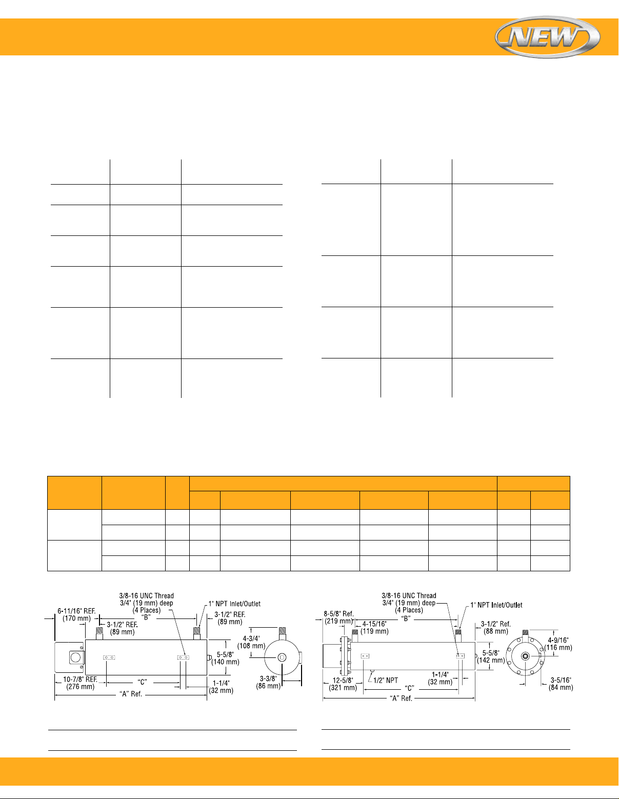
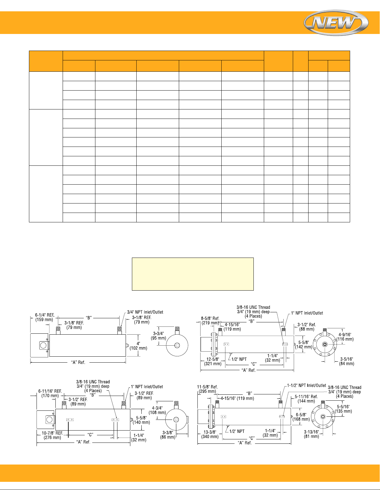
Note: Circulation heater mounting lug design
and location in the assembly drawings shown
are standard. Designs can be modified to fit
customer installation. Consult Omega with your
requirements.
Drawing
3
Drawing
4
To order, call 1-800-826-6342 or shop online at omega.com
SM
7
Page 8
Drawing
5
Drawing
6
Circulation Heaters
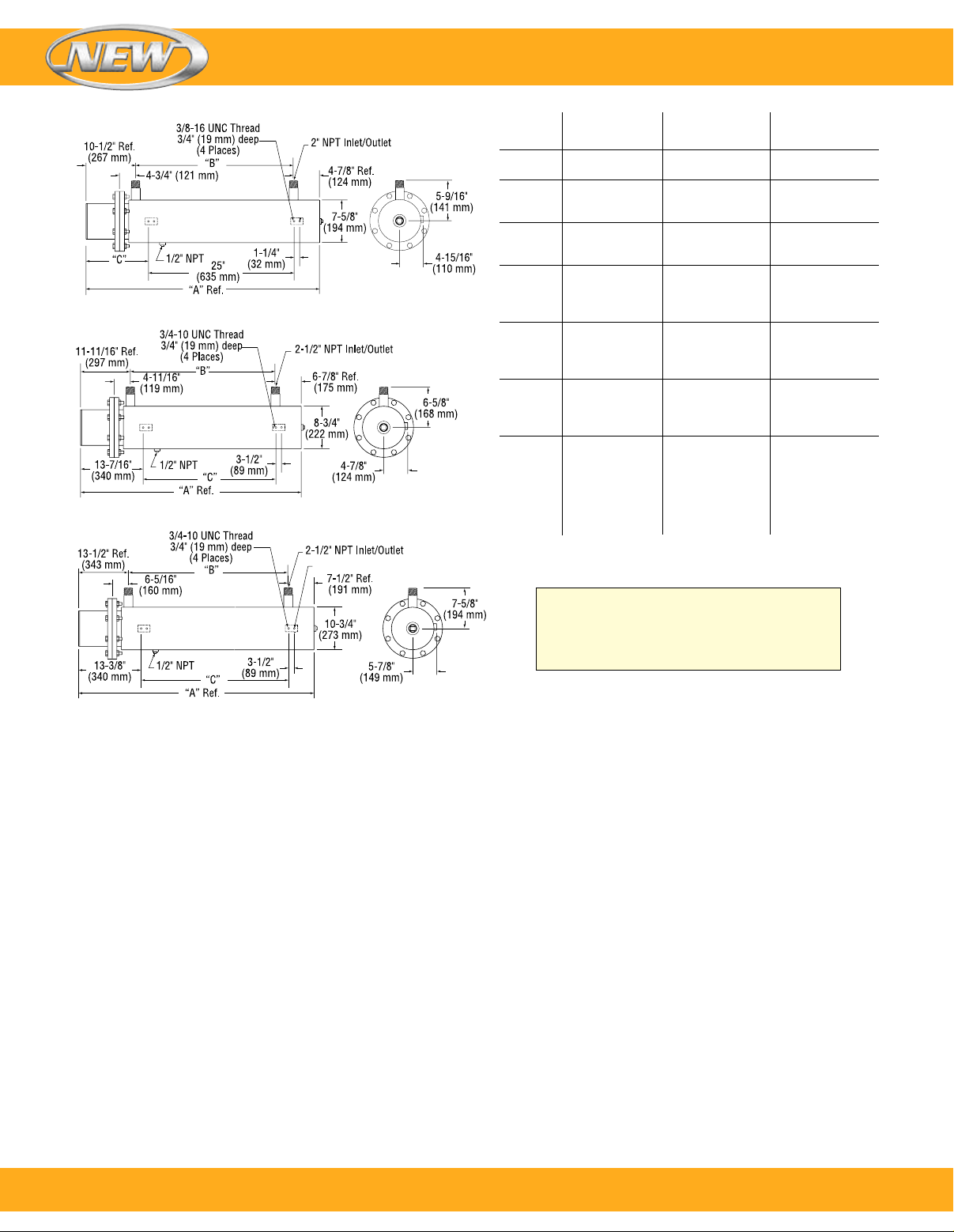
Drawing “A” “B” “C”
Number inch mm inch mm inch mm
1.1 243⁄8 619 15 381 — —
1.2 323⁄8 822 23 584 — —
2.1 3211⁄16 830 221⁄2 572 161⁄2 419
2.2 4211⁄16 1084 321⁄2 826 261⁄2 673
2.3 553⁄16 1402 45 1143 39 991
3.1 345⁄8 879 221⁄2 572 161⁄2 419
3.2 445⁄8 1133 321⁄2 826 261⁄2 673
3.3 571⁄8 1451 45 1143 39 991
4.1 3713⁄16 960 201⁄2 521 17 432
4.2 485⁄16 1227 31 787 271⁄2 699
4.3 695⁄16 1761 52 1321 481⁄2 1232
4.4 905⁄16 2294 73 1854 691⁄2 1765
5.2 523⁄8 1330 37 940 151⁄4 387
5.3 637⁄8 1622 481⁄2 1232 21 533
5.4 771⁄4 1962 617⁄8 1572 271⁄2 698
5.5 901⁄4 2292 747⁄8 1902 341⁄4 870
6.1 391⁄16 992 201⁄2 521 17 432
6.2 499⁄16 1259 31 787 271⁄2 699
6.3 709⁄16 1792 52 1321 481⁄2 1232
6.4 919⁄16 2326 73 1854 691⁄2 1765
8.2 533⁄4 1365 3211⁄16 830 293⁄16 741
8.3 603⁄4 1543 3911⁄16 1008 363⁄16 919
8.4 683⁄4 1746 475⁄16 1202 4313⁄16 1113
8.5 777⁄8 1978 5613⁄16 1443 535⁄16 1354
8.6 867⁄8 2207 6513⁄16 1672 625⁄16 1583
8.7 967⁄8 2461 7513⁄16 1926 725⁄16 1837
Drawing
8
Note: Circulation heater mounting lug design
and location in the assembly drawings shown
are standard. Designs can be modified to fit
customer installation. Consult Omega with your
requirements.
8
To order, call 1-800-826-6342 or shop online at omega.com
SM
 Loading...