

Page 1
User’s Guide
M
ADE IN
Shop online at
omega.com
e-mail: [email protected]
For latest product manuals:
omegamanual.info
CDTX-45
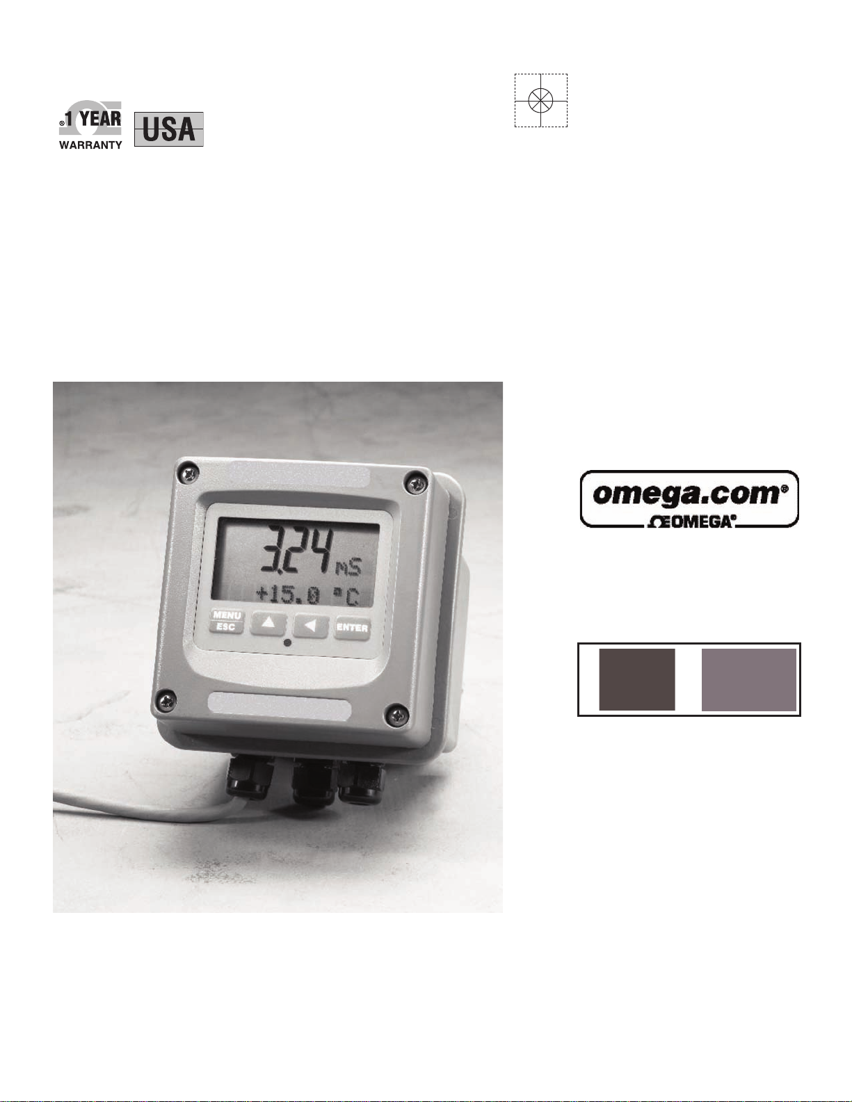
4-Electrode Conductivity Monitor
Page 2

OMEGAnet®Online Service Internet e-mail
omega.com [email protected]
Servicing North America:
U.S.A.: One Omega Drive, P.O. Box 4047
ISO 9001 Certified Stamford, CT 06907-0047
TEL: (203) 359-1660
FAX: (203) 359-7700
e-mail: [email protected]
Canada: 976 Bergar
Laval (Quebec) H7L 5A1, Canada
TEL: (514) 856-6928
FAX: (514) 856-6886
e-mail: [email protected]
For immediate technical or applicationassistance:
U.S.A. and Canada: Sales Service: 1-800-826-6342/1-800-TC-OMEGA
Customer Service: 1-800-622-2378/1-800-622-BEST
Engineering Service: 1-800-872-9436/1-800-USA-WHEN
Mexico: En Espan˜ol: (001) 203-359-7803
e-mail: [email protected]
FAX: (001) 203-359-7807
[email protected]
®
®
®
Servicing Europe:
Czech Republic: Frystatska 184, 733 01 Karviná, Czech Republic
TEL: +420 (0)59 6311899
FAX: +420 (0)59 6311114
Toll Free: 0800-1-66342
e-mail: [email protected]
Germany/Austria: Daimlerstrasse 26, D-75392 Deckenpfronn, Germany
TEL: +49 (0)7056 9398-0
FAX: +49 (0)7056 9398-29
Toll Free in Germany: 0800 639 7678
e-mail: [email protected]
United Kingdom: One Omega Drive, River Bend Technology Centre
ISO 9002 Certified Northbank, Irlam, Manchester
M44 5BD United Kingdom
TEL: +44 (0)161 777 6611
FAX: +44 (0)161 777 6622
Toll Free in United Kingdom: 0800-488-488
e-mail: [email protected]
It is the policy of OMEGA Engineering, Inc. to comply with all worldwide safety and EMC/EMI
regulations that apply. OMEGA is constantly pursuing certification of its products to the European New
Approach Directives. OMEGA will add the CE mark to every appropriate device upon certification.
The information contained in this document is believed to be correct, but OMEGA accepts no liability for any
errors it contains, and reserves the right to alter specifications without notice.
WARNING: These products are not designed for use in, and should not be used for, human applications.
Page 3

Table of Contents
PART 1 - INTRODUCTION ............................................................................................................................... 4
1.1 General ................................................................................................................................................... 4
1.2 Features .................................................................................................................................................. 5
1.3 CDTX-45 System Specifications ............................................................................................................. 7
1.4 CDTX-45 Performance Specifications ..................................................................................................... 9
PART 2 – ANALYZER MOUNTING ............................................................................................................... 10
2.1 General ................................................................................................................................................. 10
Figure 2-1 CDTX-45 Enclosure Dimensions, AC Powered Units .............................................................. 11
Figure 2-2 CDTX-45 Enclosure Dimensions, 2-Wire Unit ....................................................................... 12
2.2 Wall or Pipe Mount ............................................................................................................................... 13
Figure 2-3 Wall or Pipe mount Bracket.................................................................................................... 13
Figure 2-4 Wall Mounting Diagram ........................................................................................................ 14
Figure 2-5 Pipe Mounting Diagram ......................................................................................................... 14
2.3 Panel Mount, AC Powered Monitor ....................................................................................................... 15
Figure 2-6 115/230 VAC Panel Mount and Cut-out ................................................................................. 15
PART 3 – SENSOR MOUNTING ..................................................................................................................... 16
3.1 General ................................................................................................................................................. 16
Figure 3-1 CDTX-45 Sensor Dimensions ................................................................................................ 16
Figure 3-2 CDTX Sanitary Style and Flow-Through Tee Mount .............................................................. 17
3.2 Electrical .............................................................................................................................................. 18
Figure 3-3 Cable Description, Model CDTX-45 Sensor .......................................................................... 18
PART 4 – ELECTRICAL INSTALLATION .................................................................................................... 19
4.1 General ................................................................................................................................................. 19
4.2 Two-Wire ............................................................................................................................................. 19
Figure 4-1 Loop-Power Connection, CDTX-45 Transmitter ................................................................... 20
4.21 Load Drive ........................................................................................................................................ 21
4.3 115/230 VAC w/Relays......................................................................................................................... 21
Figure 4-2 Line Power Connection .......................................................................................................... 23
Figure 4-3 Relay Contacts ...................................................................................................................... 24
4.4 Sensor Wiring ....................................................................................................................................... 24
4.5 Direct Sensor Connection ...................................................................................................................... 24
Figure 4-4 Sensor Cable Preparation....................................................................................................... 25
4.6 Junction Box Connection ...................................................................................................................... 26
Figure 4-5 Junction Box Interconnect Wiring ......................................................................................... 26
PART 5 – CONFIGURATION .......................................................................................................................... 27
5.1 User Interface ....................................................................................................................................... 27
Figure 5-1 User Interface........................................................................................................................ 27
5.11 Keys ................................................................................................................................................. 28
5.12 Display ............................................................................................................................................. 28
5.2 Software ............................................................................................................................................... 30
5.21 Software Navigation ......................................................................................................................... 30
Figure 5-2 Software Map ....................................................................................................................... 32
- 2 -
Page 4

5.22 Measure Menu [MEASURE] ............................................................................................................. 33
5.23 Calibration Menu [CAL] ...................................................................................................................... 34
5.24 Configuration Menu [CONFIG] ........................................................................................................ 35
PART 6 - CONTROL ......................................................................................................................................... 39
Figure 6-1 Control Relay Example, Hysteresis and Two Opposite Phase Options .................................... 41
Figure 6-2 Alarm Relay Example ........................................................................................................... 42
PART 7 – CALIBRATION ................................................................................................................................ 43
7.1 Overview and Methods ......................................................................................................................... 43
7.11 1-Point Calibration Explained ............................................................................................................ 43
7.12 Zero Cal Calibration Explained.......................................................................................................... 43
7.2 Performing a Sensor Zero Calibration .................................................................................................... 44
7.3 Performing a 1-Point Calibration ........................................................................................................... 44
Figure 7-1 NaCl Reference Solution for Calibration ................................................................................ 45
7.4 Temperature Calibration........................................................................................................................ 46
PART 8 – PID CONTROLLER DETAILS ....................................................................................................... 48
8.1 PID Description .................................................................................................................................... 48
8.2 PID Algorithm ...................................................................................................................................... 48
Figure 8-1 (Ideal) PID Equation ............................................................................................................... 49
8.3 Classical PID Tuning ............................................................................................................................ 50
8.4 Common PID Pitfalls ............................................................................................................................ 51
PART 9 – SYSTEM MAINTENANCE .............................................................................................................. 52
9.1 System Checks ...................................................................................................................................... 52
9.2 Instrument Checks ................................................................................................................................ 52
9.3 Cleaning the Sensor .............................................................................................................................. 53
9.4 Troubleshooting .................................................................................................................................... 54
9.5 Display Messages ................................................................................................................................. 55
- 3 -
Page 5
Omega CDTX-45 Conductivity System Part 1– Introduction
Part 1 - Introduction
1.1 General
The Model CDTX-45 Conductivity monitor/analyzer provides an extremely
versatile measurement system for monitoring and control of conductivity over the
range of 1 µS/cm to 2.000 Siemens/cm. The instrument is offered standard as a
loop-powered transmitter for 2-wire DC applications. Since this system
configuration operates over only two low-voltage wires, it is ideal for remote
monitoring applications where line power is either unavailable or prohibitively
expensive to run.
With the optional 115/230 VAC power supply, the instrument may also be
configured for AC operation. This configuration is ideal when line power is
located close to the point of installation, and two relays and two 4-20 mA outputs
(one for conductivity and one for temperature) are required.
In all configurations, the CDTX-45 displays conductivity on the main display, and
total dissolved solids (TDS), sensor temperature, and output loop current on the
secondary line of the custom display.
WARNING: Not following operating instructions may impair safety.
NOTE: Due to the high degree of flexibility of the CDTX-45 system options, it is
important to note areas of the operating manual that detail these optional
features. The software features for the relay output option and battery option
only appear when those modules are connected and the system has been repowered.
- 4 -
Page 6

Omega CDTX-45 Conductivity System Part 1– Introduction
1.2 Features
• Standard CDTX-45 electronic transmitters are designed to be fully isolated, loop
powered instruments for 2-wire DC applications. Optional integral power supply
card for 115/230 VAC operation, and optional battery power supply card for
portable datalogging applications are available.
• High accuracy, high sensitivity system, measures from 1 to 2,000,000 uS through
7 internal automatic ranges. User display ranges include 2000 us, 2.000 mS,
20.00 mS, or 200.0 mS, 2000 mS, or 2.000 S.
• Output Hold, Output Simulate, Output Alarm, and Output Delay Functions. All
forced changes in output condition include bumpless transfer to provide gradual
return to on-line signal levels and to avoid system control shocks on both analog
outputs.
• AC power option provides dual SPDT relay operation and one additional isolated
analog output. Software settings for relay control include setpoint, deadband,
phase, delay, and failsafe. Software controls automatically appear in menu list
when hardware option card is plugged in and system power is applied.
• Selectable PID controller on main analog output. PID controller can operate with
instrument configured as loop-power transmitter, or as one of the two outputs on
the AC powered instrument. PID includes manual operation feature, and
diagnostic “stuck-controller” timer feature for relay notification of control
problems.
• Configurable for TDS display and signal output on one analog output.
• Two analog outputs on the relay version may be configured to track conductivity
and temperature, conductivity and conductivity, or conductivity and TDS. Both
analog outputs can be individually programmed to fail to specific values.
• Selectable Output Fail Alarm feature on Relay B allows system diagnostic
failures to be sent to external monitoring systems.
• Selectable Probe Timer feature on Relay B allows connection of probe cleaner
hardware or other accessories that require timed periodic relay contacts.
• Large, high contrast, custom Super-Twist display provides excellent readability
even in low light conditions. The secondary line of display utilizes 5x7 dot matrix
characters for clear message display. Two of the four measured parameters
may be on the display simultaneously.
- 5 -
Page 7

Omega CDTX-45 Conductivity System Part 1– Introduction
• 4-Electrode measurement system. Two of the electrodes are used to establish
the sensor drive potential, while the other two sense the flow of current between
the drive electrodes and maintain proper drive potential. Sensor diagnostics
monitor electrode coating/fouling, sensor leaks, and RTD condition. Diagnostic
messages provide a clear description of any problem with no confusing error
codes to look up. Messages are also included for diagnosing calibration
problems.
• Quick and easy one-point calibration method and sensor zero-cal. To provide
high accuracy, all calibration methods include stability monitors that check
temperature and main parameter stability before accepting data.
• High accuracy Pt1000 temperature input. Temperature element can be user
calibrated.
• Security lock feature to prevent unauthorized tampering with transmitter settings.
All settings can be viewed while locked, but they cannot be changed.
• High reliability, microprocessor-based system with non-volatile memory back-up
that utilizes no batteries. Low mass, surface mount PCB construction containing
no adjustment potentiometers. All factory calibrations stored in non-volatile
EEPROM.
• PEEK electrode insulator, custom rear PEEK sealing nut and triple o-ring rear
seal (FKM and EPR) allow complete submersion of the sensor.
• Custom double-shielded cross-linked cable with PE jacket for excellent chemical
resistance.
• Pt1000 RTD. The temperature element used in Omega sensors is highly
accurate and provides a highly linear output.
- 6 -
Page 8

Omega CDTX-45 Conductivity System Part 1– Introduction
1.3 CDTX-45 System Specifications
(Common to all variations)
Displayed Parameters Main input, 0 uS to 2S (2,000,000 uS)
Sensor temperature, -10.0 to 210.0 °C (23 to 410 ºF)
Loop current, 4.00 to 20.00 mA
Sensor slope
Model number and software version
PID Controller Status
Timer Status
Main Parameter Ranges Automatic or Manual selection of one of the following
display ranges,
0 to 2000 uS
0.0 to 2.000 mS
0.00 to 20.00 mS
0.0 to 200.0 mS
0 to 2000 mS
0.000 to 2.000 S
Display Large, high-contrast, Super-Twist (STN) LCD;
4-digit main display with sign, 0.75" (19.1 mm) seven-
segment characters
12-digit secondary display, 0.3" (7.6 mm) 5x7 dot matrix
characters
Keypad 4-key membrane type with tactile feedback, polycarbonate
with UV coating
Weight DC transmitter configuration: 1 lb. (0.45 kg)
Line powered unit: 1.5 lb. (0.68 kg)
Ambient Temperature Analyzer Service, -20 to 60 °C (-4 to 140 ºF)
Storage, -30 to 70 °C (-22 to 158 ºF)
Ambient Humidity 0 to 95%, indoor/outdoor use, non-condensing to rated
ambient temperature range
Altitude Up to 2000 m (6562 Ft.)
EMI/RFI Influence Designed to EN 61326-1
Output Isolation 600 V galvanic isolation
Filter Adjustable 0-9.9 minutes additional damping to 90% step
input
Temperature Input Pt1000 RTD with automatic compensation
- 7 -
Page 9

Omega CDTX-45 Conductivity System Part 1– Introduction
Sensor Fully isolated 4-electrode electrode sensor design for direct
measurement. 1” NPT process connection.
Measuring Range 0.000 to 2.000 S/cm
Wetted Materials Titanium, PEEK, FKM, EPR
(316SS when sensor is submersion mounted)
Temperature Compensation Pt1000 RTD
Sensor Cable 6 Conductor plus 2 shields,
Temperature Pressure Range The choice of sensor material/ mounting option and the
hardware used to mount the sensor will determine the
temperature and pressure ratings. Please consult the
factory for relevant temperature and pressure rating
information.
Maximum Flow Rate 10 feet (3 meters) per second
Max. Sensor-Analyzer
Distance 60 feet (18.2 meters)
Weight 1 lb. (0.45 kg)
(NOT common to all variations)
Standard 2-Wire (Loop-powered) Transmitter:
Power 16-35 VDC (2-wire device)
Enclosure: NEMA 4X, polycarbonate, stainless steel hardware,
weatherproof and corrosion resistant,
HWD: 4.4" (112 mm) x 4.4" (112 mm) x 3.5" (89 mm)
Mounting Options Wall or pipe mount bracket standard. Bracket suitable for
either 1.5” or 2” I.D. U-Bolts for pipe mounting.
Conduit Openings Two PG-9 openings with gland seals, One 1” NPT opening
with plug.
DC Cable Type Belden twisted-pair, shielded, 22 gauge or larger
Insertion Loss 16 VDC
- 8 -
Page 10

Omega CDTX-45 Conductivity System Part 1– Introduction
115/230 VAC + Dual Relay Option:
Power 115/230 VAC ± 10%, 50/60 Hz, 10 VA max
Enclosure, AC Powered NEMA 4X, polycarbonate, stainless steel hardware,
weatherproof and corrosion resistant,
HWD: 4.9" (124 mm) x 4.9" (124 mm) x 5.5" (139 mm)
Mounting Options Wall or pipe mount bracket standard. Bracket suitable for
either 1.5” or 2” I.D. U-Bolts for pipe mounting.
Panel mount adapter optional.
Conduit Openings Three ½” NPT openings. Gland seals supplied but not
installed.
Relays, Electromechanical: Two SPDT, 6 amp @ 250 VAC, 5 amp @ 24 VDC
contacts. Software selection for setpoint, phase, delay,
deadband, hi-lo alarm, and failsafe. A-B indicators on
main LCD.
Analog Outputs Two 4-20 mA outputs. Output one programmable for
conductivity or PID. Output 2 programmable for
conductivity, temperature, or TDS. Max load 500 Ohms for
each output. Outputs ground isolated and isolated from
each other.
1.4 CDTX-45 Performance Specifications
(Common to all variations)
Accuracy 0.5% of user range, or better (± 2 μS)
Repeatability 0.2% of user range, or better (± 2 μS)
Sensitivity 0.05% of user ranges (± 2 μS)
Stability 0.2% of user range per 24 hours, non-cumulative
Warm-up Time 7 seconds to rated performance
Supply Voltage Effects DC version only, ± 0.05% of user range
Instrument Response Time 6 seconds to 90% of step input at lowest setting
Temperature Drift Span or zero, 0.04% of span/°C
- 9 -
Page 11

OMEGA CDTX-45 Conductivity System Part 2– Analyzer Mounting
Part 2 – Analyzer Mounting
2.1 General
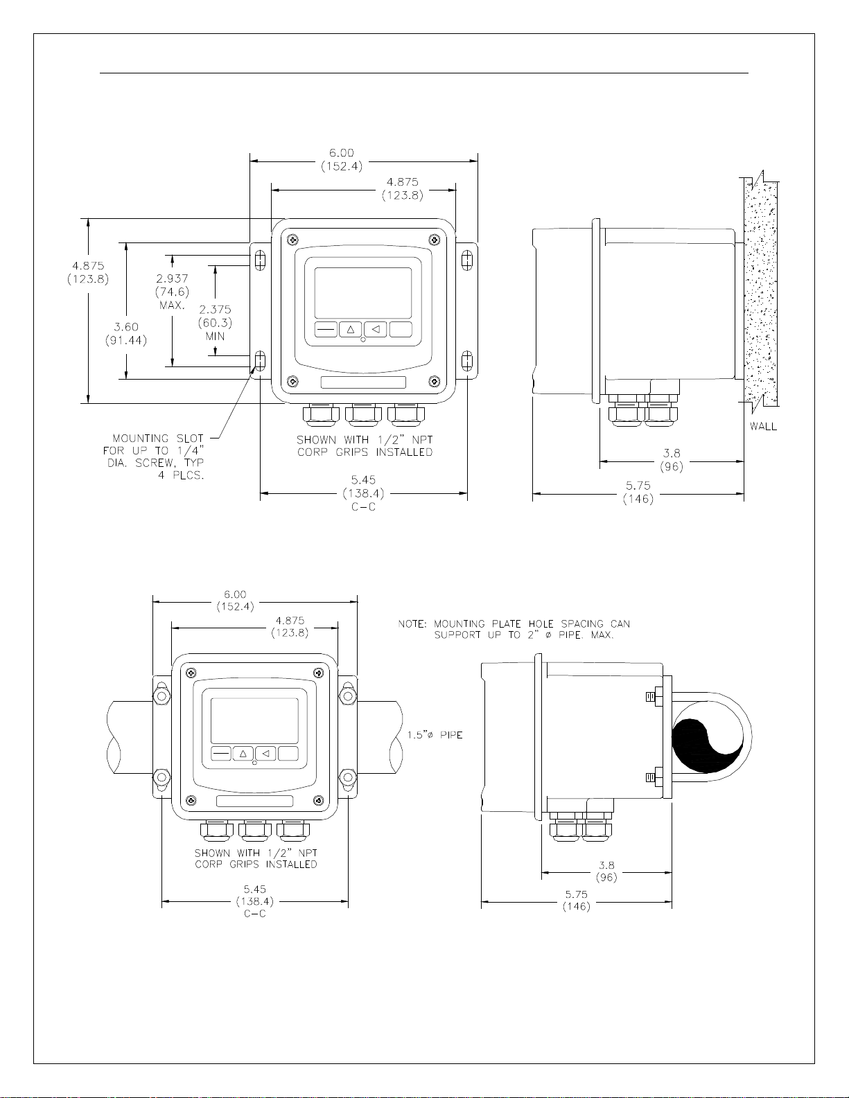
All CDTX-45 Series instruments offer maximum mounting flexibility. A bracket is
included with each unit that allows mounting to walls or pipes. In all cases,
choose a location that is readily accessible for calibrations. Also consider that it
may be necessary to utilize a location where solutions can be used during the
calibration process. To take full advantage of the high contrast display, mount
the instrument in a location where the display can be viewed from various angles
and long distances.
Locate the instrument in close proximity to the point of sensor installation - this
will allow easy access during calibration. The standard cable length of the
conductivity sensor is 20 feet. For sensor cables longer than 20 feet, use the
optional junction box and sensor interconnect cable.
Due to the flexibility of the instrument design, some of the mounting features
change based on the configuration that was ordered. For example, the 2-wire
transmitter version is different for the 115/230 VAC controller because the rear of
the enclosure is much deeper when the AC powered unit is used. In addition, the
AC powered unit has an integrated panel mount flange requiring a single cutout
for flush mounting. In the 2-wire transmitter configuration, just the front of the
enclosure can be mounted, but the cutout also requires accurate location of 4
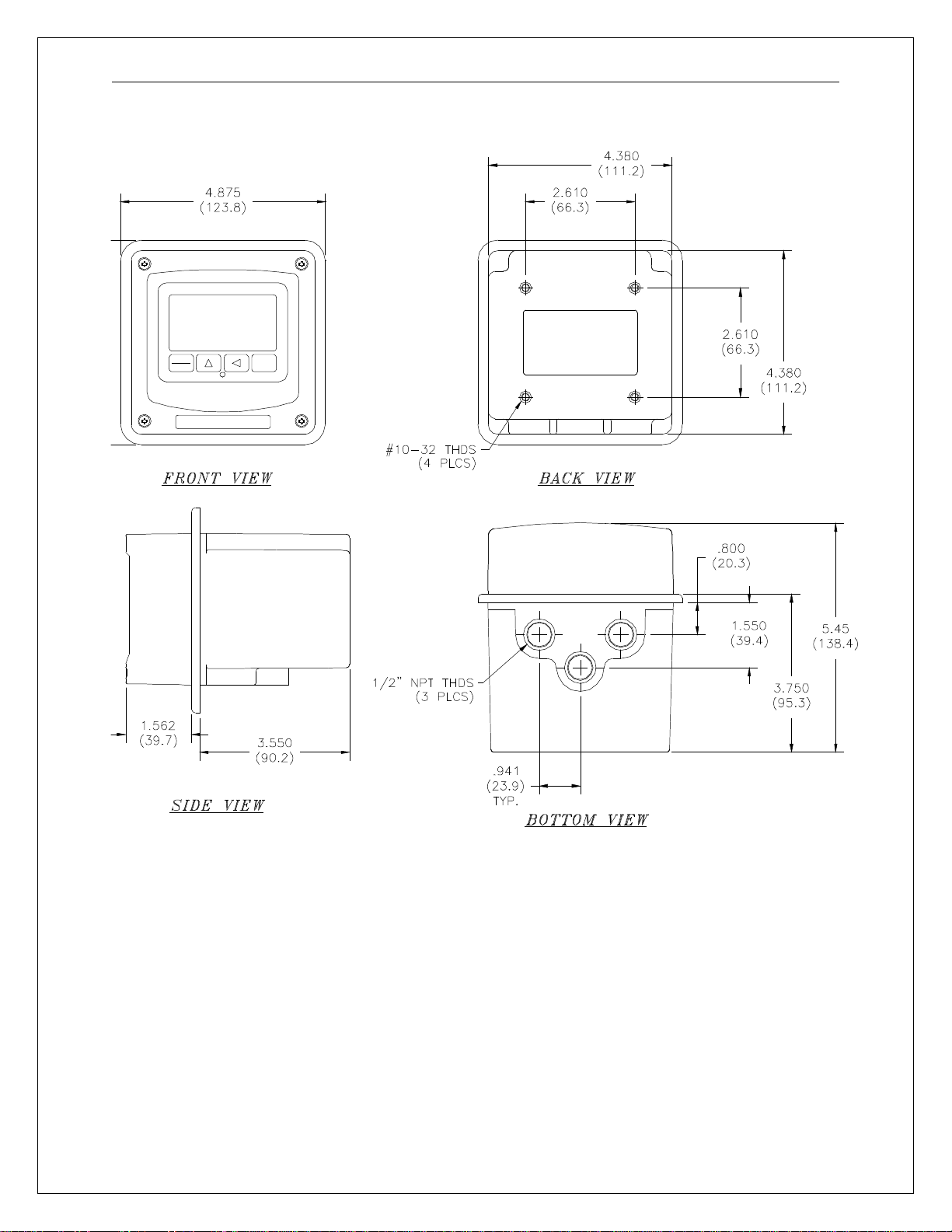
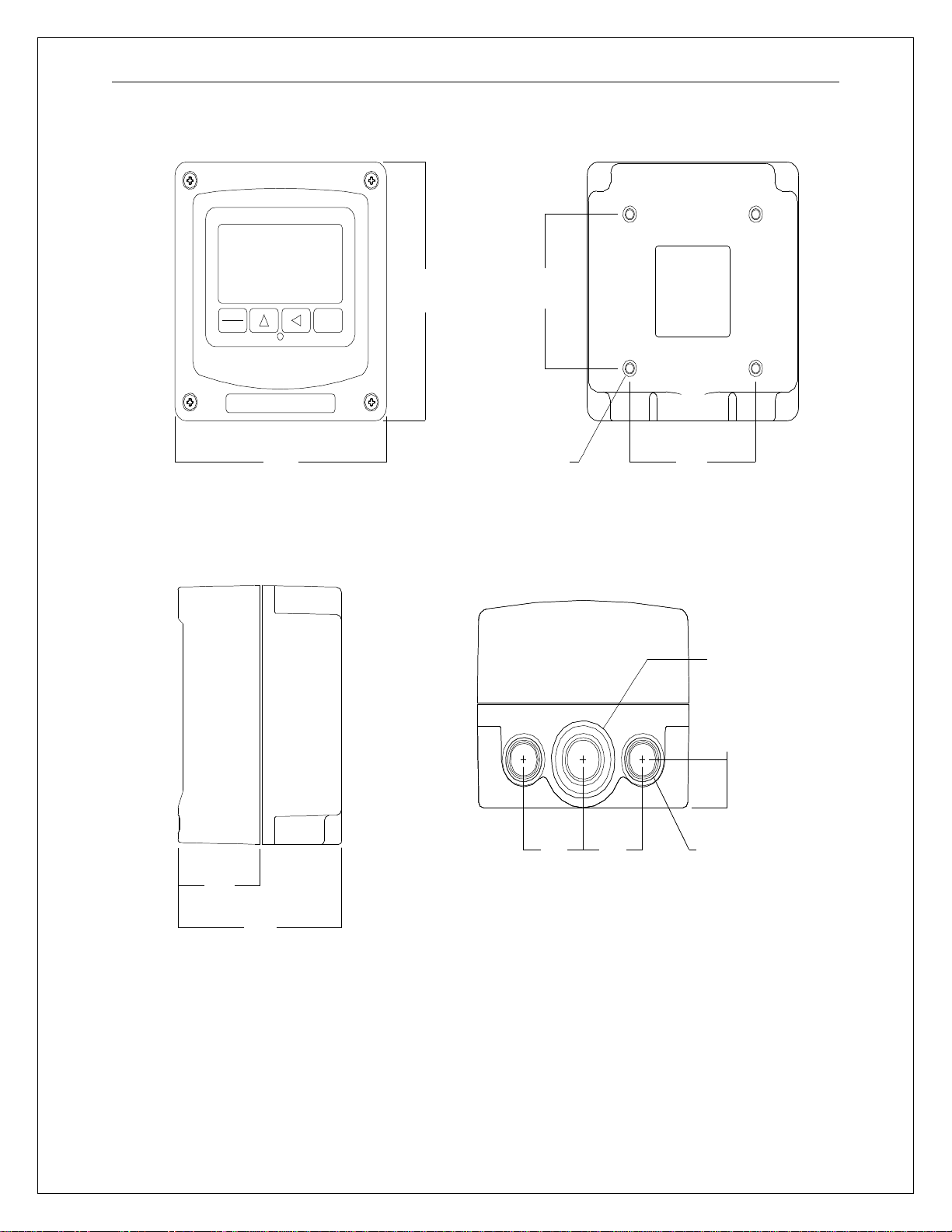
mounting holes. Refer to Figures 2-1 and 2-2 for detailed dimensions of each
type of system.
- 10 -
Page 12
OMEGA CDTX-45 Conductivity System Part 2– Analyzer Mounting
MENU
ESC
ENTER
Figure 2-1 CDTX-45 Enclosure Dimensions, AC Powered Units
- 11 -
Page 13
OMEGA CDTX-45 Conductivity System Part 2– Analyzer Mounting
MENU
ESC
4.38
(111.2)
FRONT VIEW
1.68
(42.7)
3.45
(87.6)
ENTER
4.38
(111.2)
#10-32 UNF
(4 PLACES)
2.61
(66.3)
BACK VIEW
1.23
(31.2)
1.23
(31.2)
BOTTOM VIEW
BOTTOM VIEW
2.61
(66.3)
1" NPT
.82
(20.8)
PG-9 PORT
(2 PLACES)
SIDE VIEW
Figure 2-2 CDTX-45 Enclosure Dimensions, 2-Wire Unit
- 12 -
Page 14
OMEGA CDTX-45 Conductivity System Part 2– Analyzer Mounting
2.2 Wall or Pipe Mount
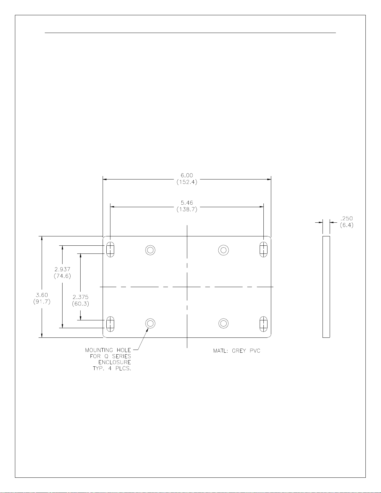
A PVC mounting bracket with attachment screws is supplied with each
transmitter (see Figure 2-3 for dimensions). The multi-purpose bracket is
attached to the rear of the enclosure using the four flat head screws. The
instrument is then attached to the wall using the four outer mounting holes in the
bracket. These holes are slotted to accommodate two sizes of u-bolt that may be
used to pipe mount the unit. Slots will accommodate u-bolts designed for 1½“ or
2” pipe. The actual center to center dimensions for the u-bolts are shown in the
drawing. Note that these slots are for u-bolts with ¼-20 threads.
Figure 2-3 Wall or Pipe mount Bracket
- 13 -
Page 15
OMEGA CDTX-45 Conductivity System Part 2– Analyzer Mounting
MENU
ESC
Figure 2-4 Wall Mounting Diagram
ENTER
MENU
ESC
ENTER
Figure 2-5 Pipe Mounting Diagram
- 14 -
Page 16
OMEGA CDTX-45 Conductivity System Part 2– Analyzer Mounting
2.3 Panel Mount, AC Powered Monitor
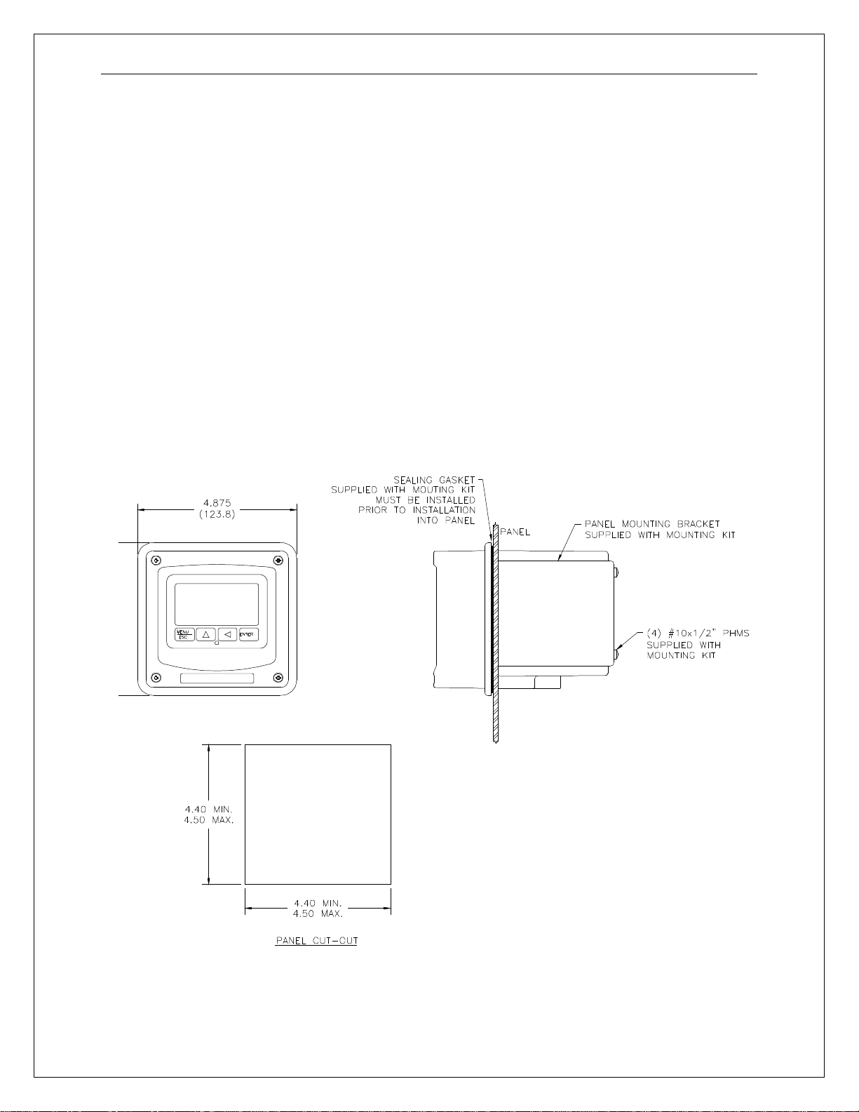
Panel mounting of an AC powered monitor uses the panel mounting flange
molded into the rear section of the enclosure. Figure 2-6 provides dimensions for
the panel cutout required for mounting.
The panel mounting bracket kit must be ordered separately. This kit contains a
metal retainer bracket that attaches to the rear of the enclosure, 4 screws for
attachment of this bracket, and a sealing gasket to insure that the panel mounted
monitor provides a water tight seal when mounted to a panel.
The sealing gasket must first be attached to the enclosure. The gasket contains
an adhesive on one side so that it remains in place on the enclosure. Remove
the protective paper from the adhesive side of the gasket and slide the gasket
over the back of the enclosure so that the adhesive side lines up with the back of
the enclosure flange. Once in place, you can proceed to mount the monitor in
the panel.
Figure 2-6 115/230 VAC Panel Mount and Cut-out
- 15 -
Page 17
OMEGA CDTX-45 Conductivity System Part 3 – Sensor Mounting
Part 3 – Sensor Mounting
3.1 General
The CDTX-45 Conductivity Sensor is designed for industrial and municipal
process applications. Mounting options include flow-through, submersion,
insertion (special hardware required), or integral mount to the CDTX-45
Conductivity Monitor/Analyzer. The sensor-to-analyzer distance must not exceed
60 feet (18.2 meters).
Calibrate the sensor before placing it into the process. See Part 6 of this manual
for detailed calibration instructions.
The sensor comes with a removable guard that surrounds the electrode face.
This guard minimizes interference effects in tight locations where the sensor face
is close to surrounding objects. If it is removed, take care to leave at least 1 in3
of space in front of the electrodes. If the guard is to be used, the sensor must be
calibrated with it in place, since the guard affects the sensor cell constant.
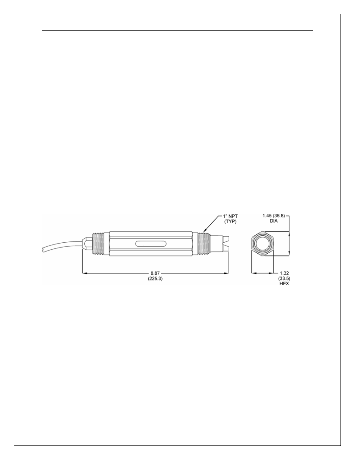
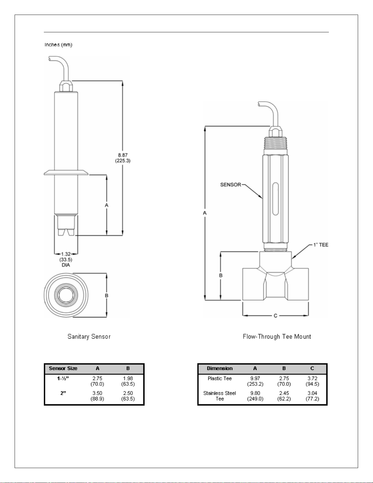
Figure 3-1 CDTX-45 Sensor Dimensions
- 16 -
Page 18
OMEGA CDTX-45 Conductivity System Part 3 – Sensor Mounting
Figure 3-2 CDTX Sanitary Style and Flow-Through Tee Mount
- 17 -
Page 19
OMEGA CDTX-45 Conductivity System Part 3 – Sensor Mounting
3.2 Electrical
The Model CDTX-45 sensor comes standard with 15 feet of 6 conductor double
shielded cable. The cable is permanently attached to the sensor, and a PEEK
cordgrip is used to seal around the cable. Nevertheless, the cable should always
be kept as clean and dry as possible.
DANGER: DO NOT connect sensor cable to power lines. Serious injury
may result.
Take care to route sensor cable away from AC power lines, adjustable frequency
drives, motors, or other noisy electrical signal lines. Do not run signal lines in the
same conduit as AC power lines. Run signal cable in dedicated metal conduit if
possible. For optimum electrical noise protection, run an earth ground wire to the
ground terminal in the transmitter
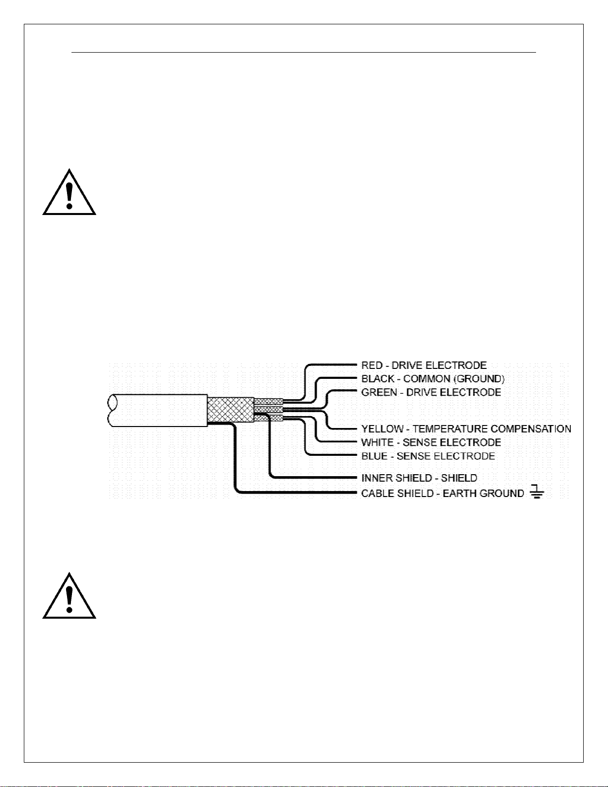
Refer to Figure 3-3, Cable Description and Figure 4-1, Wiring Diagram for
illustrative details on electrical installation.
Figure 3-3 Cable Description, Model CDTX-45 Sensor
Only 6-wire shielded interconnect cable must be used when connecting the
Model CDTX-45 sensor to the analyzer. This high-performance, double shielded,
polyethylene jacketed cable is specially designed to provide the proper signal
shielding for the sensor used in this system. No substitutions can be made.
Substituted cables may cause problems with system performance.
- 18 -
Page 20
OMEGA CDTX-45 Conductivity System Part 4 – Electrical Installation
Part 4 – Electrical Installation
4.1 General
The CDTX-45 is powered in one of two ways, depending on the version
purchased. The 2-wire version is a 16-35 VDC powered transmitter. The
integral 115/230 VAC version requires line power. Please verify the type of unit
before connecting any power.
WARNING: Do not connect AC line power to the 2-wire module.
Severe damage will result.
Important Notes:
1. Use wiring practices that conform to all national, state and local
electrical codes. For proper safety as well as stable measuring
performance, it is important that the earth ground connection be
made to a solid ground point (Figure 4-1). The AC power
supply contains a single 100mA (115V) or 50mA (230V) slo-blo
fuse. The fuse F1 is located adjacent to TB5 and is easily
replaceable.
2. Do NOT run sensor cables or instrument 4-20 mA output wiring
in the same conduit that contains AC power wiring. AC power
wiring should be run in a dedicated conduit to prevent electrical
noise from coupling with the instrumentation signals.
3. This analyzer must be installed by specifically trained personnel
in accordance with relevant local codes and instructions
contained in this operating manual. Observe the analyzer's
technical specifications and input ratings. Proper electrical
disconnection means must be provided prior to the electrical
power connected to this instrument, such as a circuit breaker rated 250 VAC, 2 A minimum. If one line of the line power
mains is not neutral, use a double-pole mains switch to
disconnect the analyzer.
4.2 Two-Wire
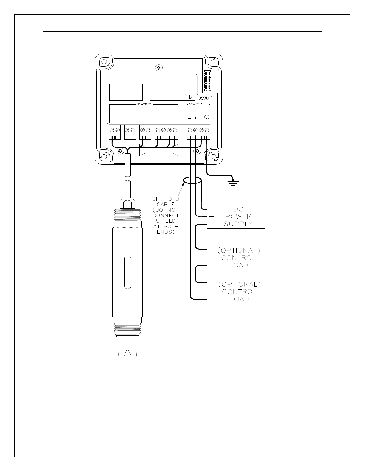
In the two-wire configuration, a separate DC power supply must be used to
power the instrument. The exact connection of this power supply is dependent
on the control system into which the instrument will connect. See Figure 4-1 for
further details. Any twisted pair shielded cable can be used for connection of the
instrument to the power supply. Route signal cable away from AC power lines,
adjustable frequency drives, motors, or other noisy electrical signal lines. Do not
run sensor or signal cables in conduit that contains AC power lines or motor
leads.
- 19 -
Page 21
OMEGA CDTX-45 Conductivity System Part 4 – Electrical Installation
Options: XXXX
Voltage: XXXX
S/N: XXXX
P/N: 07-XXXX
Model: Q45C4
RED
BLUE
1 2
3 4 5 12
GREEN
WHITE
6
YELLOW7BLACK
8 11 14
Figure 4-1 Loop-Power Connection, CDTX-45 Transmitter
Notes: 1. Voltage between Terminals 11 and 12 MUST be between 16 and 35 VDC.
2. Earth ground into Terminal 14 is STRONGLY recommended. This connection
can greatly improve stability in electrically noisy environments.
OR DAMAGE MAY RESULT
BEFORE SERVICING
DISCONNECT POWER
WARNING
SHLD
13109
- 20 -
Page 22

OMEGA CDTX-45 Conductivity System Part 4 – Electrical Installation
(Power Supply Voltage
- 16)
Power Supply Voltage (VDC)
Total Load (Ohms)
4.21 Load Drive
The amount of resistance that the analog output can drive in the 115/230
VAC version is fixed. However, in the two-wire configuration, the loaddrive level is dependant on the DC supply voltage provided to the
controller.
The two-wire instrument can operate on a power supply voltage of
between 16 and 35 VDC. The available load drive capability can be
calculated by applying the formula V/I=R, where V=load drive voltage,
I=maximum loop current (in Amperes), and R=maximum resistance load
(in Ohms).
To find the load drive voltage of the two-wire CDTX-45, subtract 16 VDC
from the actual power supply voltage being used (the 16 VDC represents
insertion loss). For example, if a 24 VDC power supply is being used, the
load drive voltage is 8 VDC.
The maximum loop current of the two-wire Q45 is always 20.00 mA, or .02
A. Therefore,
For example, if the power supply voltage is 24 VDC, first subtract 16 VDC,
then divide the remainder by .02. 8/.02 = 400; therefore, a 400 Ohm
maximum load can be inserted into the loop with a 24 VDC power supply.
Similarly, the following values can be calculated:
4.3 115/230 VAC w/Relays
In the 115/230 VAC configuration, a DC power supply is mounted into the inside
rear of the enclosure. The power supply must be ordered with the proper
operating voltage. Verify that the unit requires either 115 VAC or 230 VAC
before installing. Also verify that power is fully disconnected before attempting to
wire.
.02
16.0 0
20.0 200
24.0 400
30.0 700
35.0 950
= R
MAX
- 21 -
Page 23

OMEGA CDTX-45 Conductivity System Part 4 – Electrical Installation
WARNING
Disconnect line power voltage BEFORE connecting
line power wires to Terminal TB5 of the power supply.
wire
ly is configured
for 115 VAC or 230 VAC operation at the factory at
time of order, and the power supply is labeled as
such. Do NOT connect voltages other than the
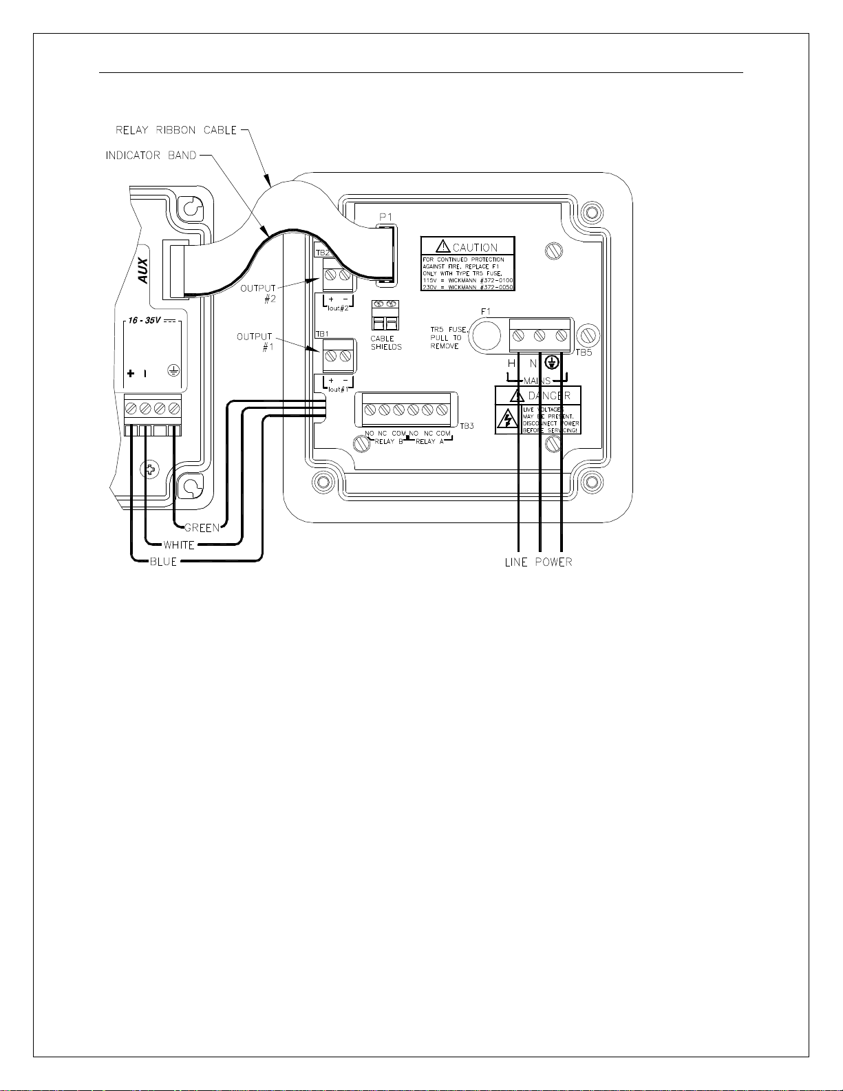
AC powered CDTX-45 systems are supplied with 3 cable gland fittings and two
½” conduit adapters. One of the cable glands has a larger hole in the rubber
gland and should be used for the power cord entry if a flexible power cord will be
used for installation. One of the cable glands with the smaller gland opening
should normally be used for the sensor cable. Cable glands and conduit hubs
will screw into any of the three threaded holes on the bottom of the enclosure.
Connect HOT, NEUTRAL, and GROUND to the matching designations on
terminal strip TB5.
The analog outputs from the system are present at terminals TB1 and TB2. The
loop-load limitation in this configuration is 500 Ohms maximum for each output.
Also note that these two outputs are completely isolated from each other to
insure that ground loops do not result from the connection of both outputs to the
same device such as a PLC or DCS.
In the line-powered unit, a ribbon cable connects the power supply assembly with
the microprocessor assembly located in the front section of the enclosure. This
cable can be removed during installation to facilitate wiring if desired. It is best to
unplug only one end. The ribbon cable has a marking stripe on one edge that is
used to indicate proper orientation. The indicator stripe should be on the bottom
edge of the cable when installed as shown in Figure 4-2.
The power supply accepts only standard threesingle phase power. The power supp
labeled requirement to the input.
- 22 -
Page 24
OMEGA CDTX-45 Conductivity System Part 4 – Electrical Installation
SHLD
12111413
Figure 4-2 Line Power Connection
The power strip, TB5, allows up to 12 AWG wire. A wire gauge of 16
AWG is recommended to allow for an easy pass-through into the ½” NPT
ports when wiring.
- 23 -
Page 25
OMEGA CDTX-45 Conductivity System Part 4 – Electrical Installation
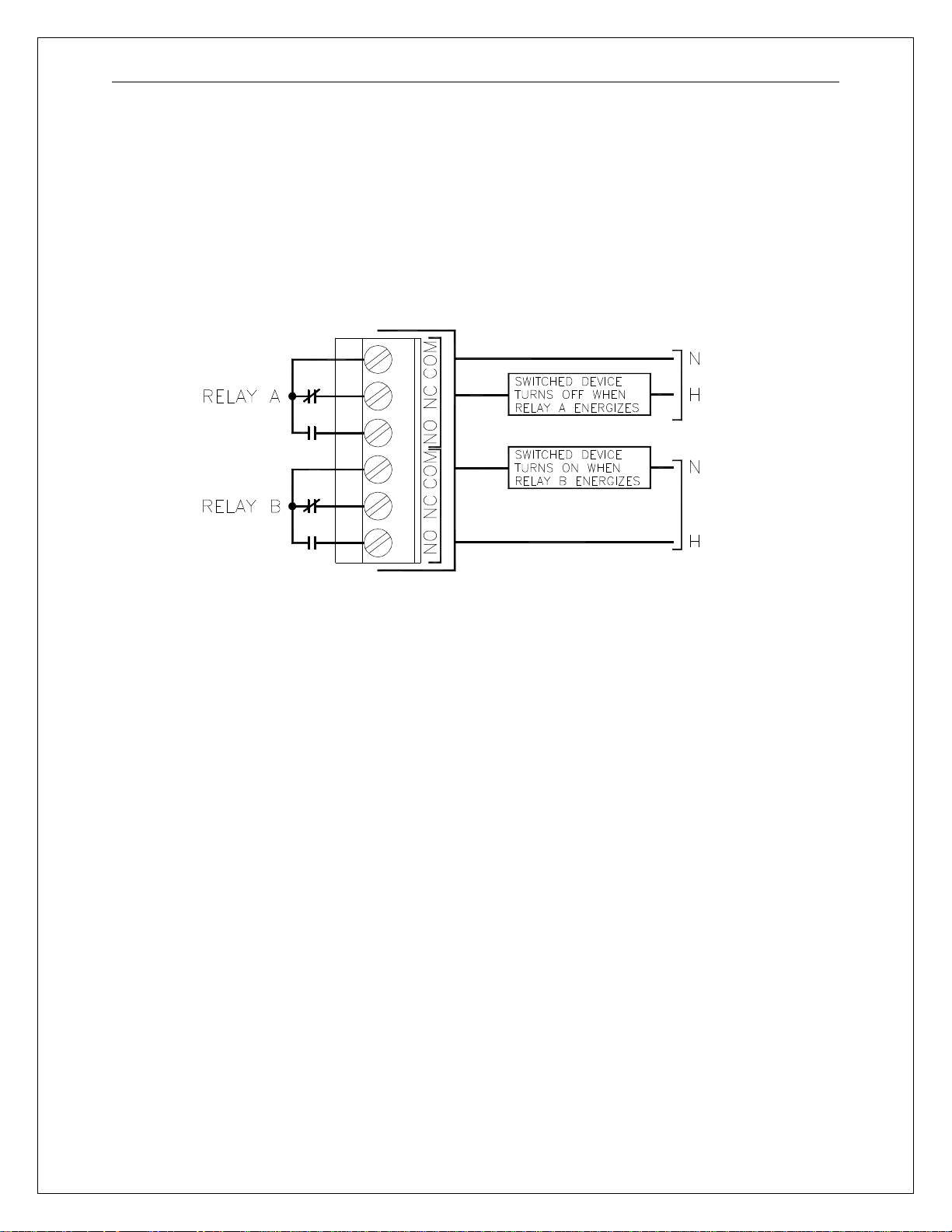
Two sets of SPDT relay contacts are provided on the power supply board. None
of the relay contacts are powered. The user must supply the proper power to the
contacts. For applications that require the same switched operating voltage as
the transmitter (115 or 230 V), power may be jumpered from the power input
terminals at TB5. Relay wiring is connected at TB3 as shown below. Note that
the relay contact markings are shown in the NORMAL mode. Programming a
relay for “Failsafe” operation reverses the NO and NC positions in this diagram.
Figure 4-3 Relay Contacts
4.4 Sensor Wiring
The sensor cable can be quickly connected to the CDTX-45 terminal strip by
matching the wire colors on the cable to the color designations on the label in the
monitor. A junction box is also available to provide a break point for long sensor
cable runs. Route signal cable away from AC power lines, adjustable frequency
drives, motors, or other noisy electrical signal lines. Do not run sensor or signal
cables in conduit that contains AC power lines or motor leads.
4.5 Direct Sensor Connection
Sensor connections are made in accordance with Figure 4-1. The sensor cable
can be routed into the enclosure through one of cord-grips supplied with the unit.
Routing sensor wiring through conduit is only recommended if a junction box is to
be used. Some loose cable is needed near the installation point so that the
sensor can be inserted and removed easily from the flowcell.
- 24 -
Page 26
OMEGA CDTX-45 Conductivity System Part 4 – Electrical Installation
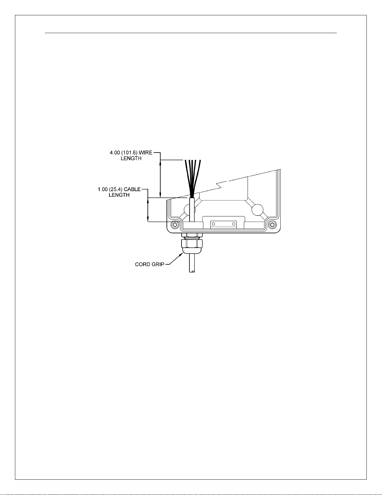
Cord-grips used for sealing the cable should be snugly tightened after electrical
connections have been made to prevent moisture incursion. When stripping
cables, leave adequate length for connections in the transmitter enclosure as
shown below. The standard 20 ft. sensor cable normally supplied with the
system is already stripped and ready for wiring. This cable can be cut to a
shorter length if desired to remove extra cable in a given installation. Do not cut
the cable so short as to make installation and removal of the sensor difficult.
.
Figure 4-4 Sensor Cable Preparation
- 25 -
Page 27
OMEGA CDTX-45 Conductivity System Part 5 – Configuration
4.6 Junction Box Connection
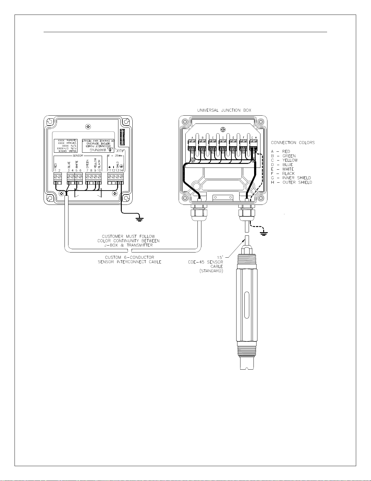
For installations where the sensor is to be located more than 30
feet from the monitor (max. 100 feet), a junction box must be used.
The junction box is shown in Figure 4-5. Consult drawing below for
Junction Box wiring diagram.
Figure 4-5 Junction Box Interconnect Wiring
- 26 -
Page 28
OMEGA CDTX-45 Conductivity System Part 5 – Configuration
ENTER
MENU ICONS
12-CHARACTER
Part 5 – Configuration
5.1 User Interface
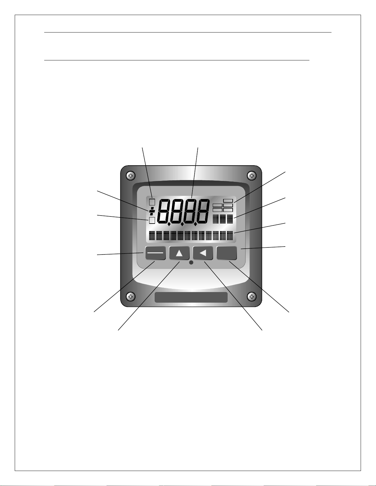
The user interface for the CDTX-45 Series instrument consists of a custom
display and a membrane keypad. All functions are accessed from this user
interface (no internal jumpers, pots, etc.).
SIGN
RELAY/LO-BAT
INDICATOR
4-KEY USER
INTERFACE
RELAY
INDICATOR
A
B
MENU
ESC
4-DIGIT
MAIN DISPLAY
MENU ICONS
CAL
UNITS
CONF
12-CHARACTER
SECONDARY
DISPLAY
MEMBRANE
KEYPAD
DIAG
FAIL
HOLD
UNITS
SECONDARY
DISPLAY
MEMBRANE
KEYPAD
MENU/ESCAPE
KEY
UP ARROW
KEY
Figure 5-1 User Interface
- 27 -
ENTER KEY
LEFT ARROW
KEY
Page 29
OMEGA CDTX-45 Conductivity System Part 5 – Configuration
5.11 Keys
All user configurations occur through the use of four membrane keys. These
keys are used as follows:
MENU/ESC To scroll through the menu section headers or to escape
from anywhere in software. The escape sequence allows
the user to back out of any changes in a logical manner.
Using the escape key aborts all changes to the current
screen and backs the user out one level in the software tree.
The manual will refer to this key as either MENU or ESC,
depending upon its particular function. In the batterypowered version of the CDTX-45 , this is also the ON button.
UP (arrow) To scroll through individual list or display items and to
change number values.
LEFT (arrow) To move the cursor from right to left during changes to a
number value.
ENTER To select a menu section or list item for change and to store
any change.
5.12 Display
The large custom display provides clear information for general
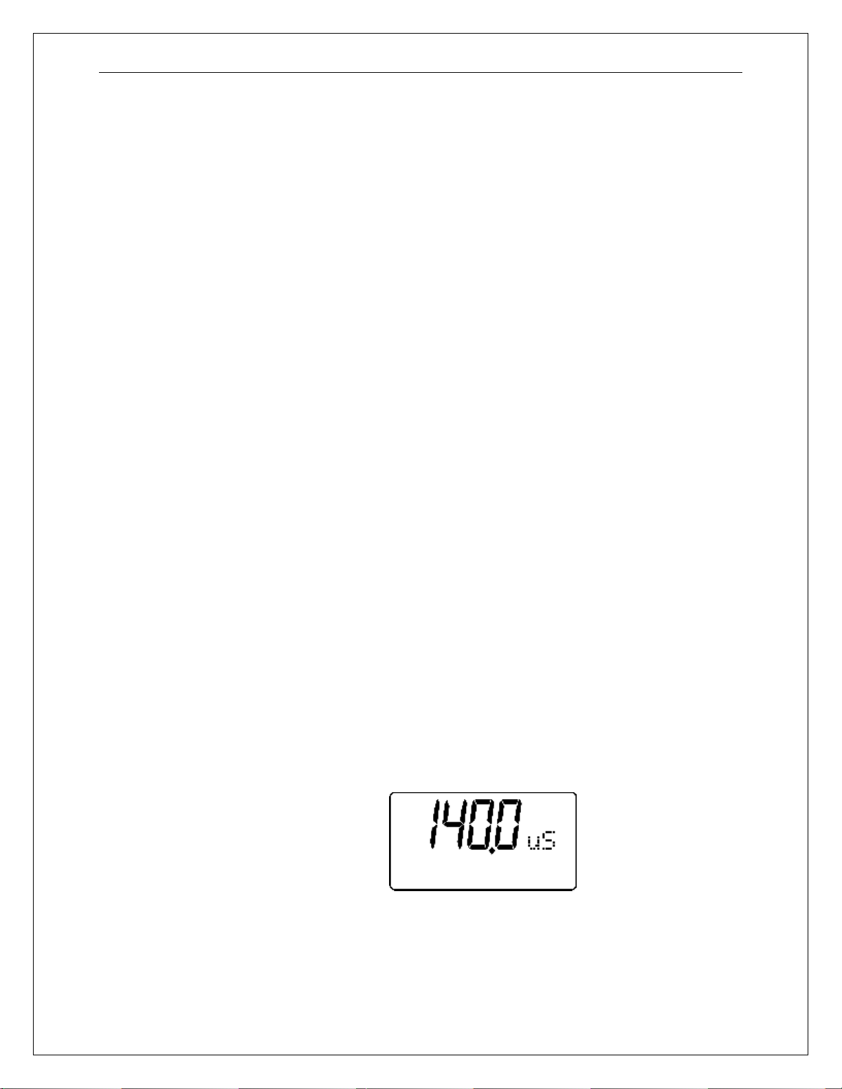
measurement use and user configuration. There are three main areas of
the display: the main parameter display, the secondary message line, and
the icon area.
Main Parameter During normal operation, the main parameter display
indicates the present process input with sign and units. This
main display may be configured to display any of the main
measurements that the system provides. During
configuration, this area displays other useful set-up
information to the user.
- 28 -
Page 30
OMEGA CDTX-45 Conductivity System Part 5 – Configuration
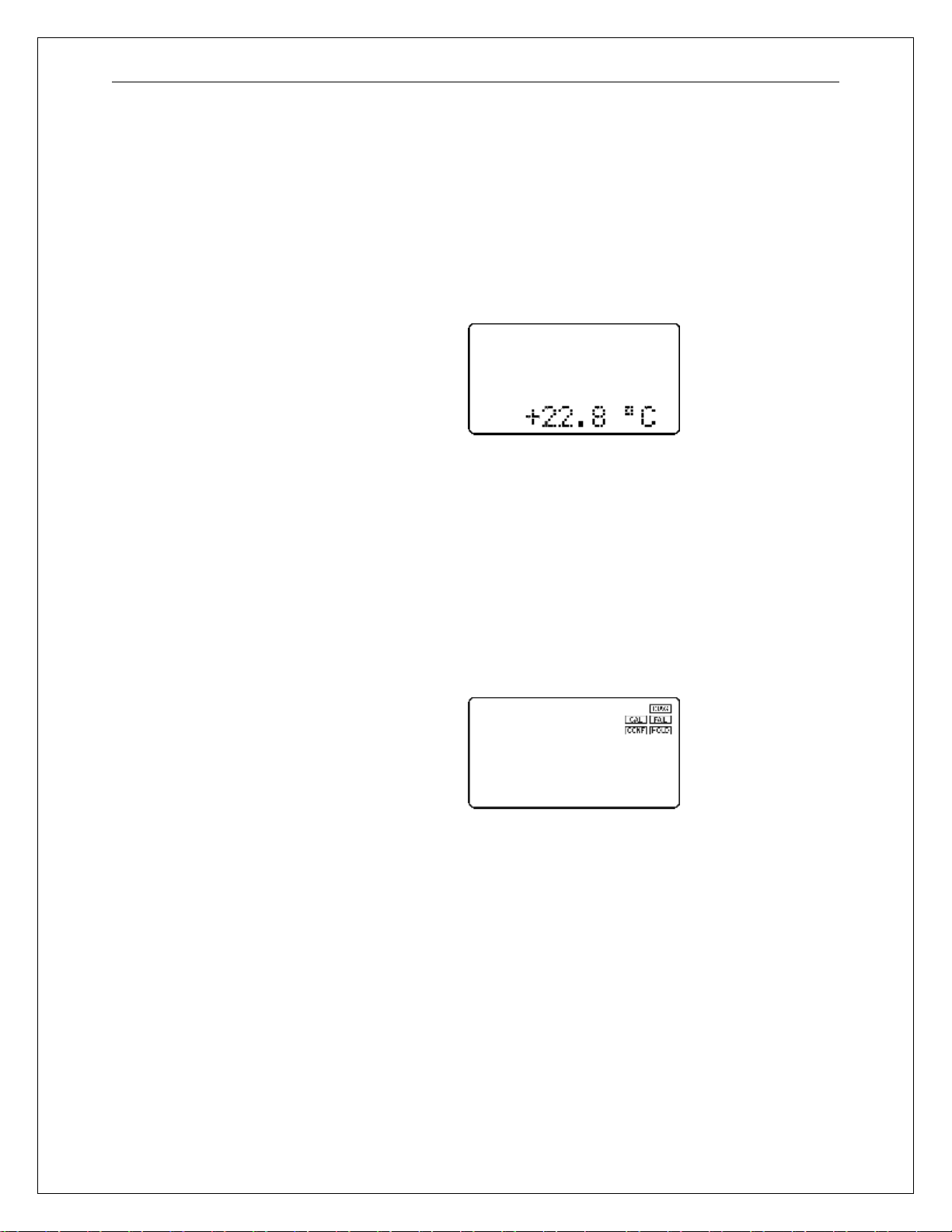
Lower Line During normal operation, the lower line of the display
indicates user-selected secondary measurements that the
system is making. This also includes calibration data from
the last calibration sequence and the transmitter model
number and software version. During configuration, the
lower line displays menu items and set-up prompts to the
user. Finally, the lower line will display error messages
when necessary. For a description of all display messages,
refer to Section 8.5.
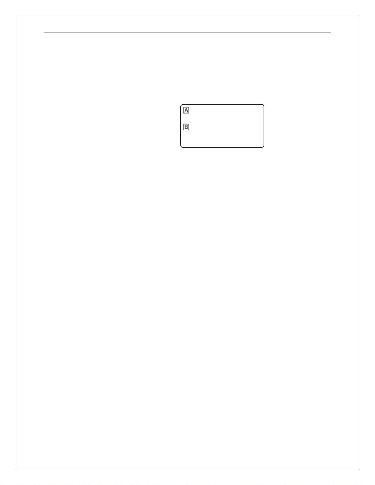
Icon Area The icon area contains display icons that assist the user in
set-up and indicate important states of system functions.
The CAL, CONFIG, CNTRL, and DIAG icons are used to tell
the user what branch of the software tree the user is in while
scrolling through the menu items. This improves software
map navigation dramatically. Upon entry into a menu, the
title is displayed (such as CAL), and then the title disappears
to make way for the actual menu item. However, the icon
stays on.
HOLD The HOLD icon indicates that the current output of the
transmitter has been put into output hold. In this case, the
output is locked to the last input value measured when the
HOLD function was entered. HOLD values are retained
even if the unit power is cycled.
FAIL The FAIL icon indicates that the system diagnostic function
has detected a problem that requires immediate attention.
This icon is automatically cleared once the problem has
been resolved.
- 29 -
Page 31
OMEGA CDTX-45 Conductivity System Part 5 – Configuration
Relay Area A/B The relay area contains two icons that indicate the state of
the system relays (if the relay card is installed). If the battery
board is installed instead, the B icon indicates that the
battery voltage is at a low level. The battery power option
and the relay option cannot be installed together.
5.2 Software
The software of the CDTX-45 is organized in an easy to follow menu-based
system. All user settings are organized under five menu sections: Measure,
Calibration [CAL], Configuration [CONFIG], Control [CONTROL] and Diagnostics
[DIAG].
Note: The default Measure Menu is display-only and has no menu icon.
5.21 Software Navigation
Within the CAL, CONFIG, CONTROL, and DIAG menu sections is a list of
selectable items. Once a menu section (such as CONFIG) has been
selected with the MENU key, the user can access the item list in this
section by pressing either the ENTER key or the UP arrow key. The list
items can then be scrolled through using the UP arrow key. Once the last
item is reached, the list wraps around and the first list item is shown again.
The items in the menu sections are organized such that more frequently
used functions are first, while more permanent function settings are later
in the list. See Figure 5-2 for a visual description of the software.
Each list item allows a change to a stored system variable. List items are
designed in one of two forms: simple single variable, or multiple variable
sequences. In the single variable format, the user can quickly modify one
parameter - for example, changing temperature display units from °F to
°C. In the multiple variable sequence, variables are changed as the result
of some process. For example, the calibration of conductivity generally
requires more than one piece of information to be entered. The majority of
the menu items in the software consist of the single variable format type.
- 30 -
Page 32

OMEGA CDTX-45 Conductivity System Part 5 – Configuration
Any data that may be changed will be flashing. This flashing indicates
user entry mode and is initiated by pressing the ENTER key. The UP
arrow key will increase a flashing digit from 0 to 9. The LEFT arrow key
moves the flashing digit from right to left. Once the change has been
completed, pressing ENTER again stores the variable and stops the
flashing. Pressing ESC aborts the change and also exits user entry mode.
The starting (default) screen is always the Measure Menu. The UP arrow
key is used to select the desired display. From anywhere in this section
the user can press the MENU key to select one of the four Menu Sections.
The UP arrow icon next to all list items on the display is a reminder to
scroll through the list using the UP arrow key.
To select a list item for modification, first select the proper menu with the
MENU key. Scroll to the list item with the UP arrow key and then press
the ENTER key. This tells the system that the user wishes to perform a
change on that item. For single item type screens, once the user presses
the ENTER key, part or all of the variable will begin to flash, indicating that
the user may modify that variable using the arrow keys. However, if the
instrument is locked, the transmitter will display the message Locked! and
will not enter user entry mode. The instrument must be unlocked by
entering the proper code value to allow authorized changes to user
entered values. Once the variable has been reset, pressing the ENTER
key again causes the change to be stored and the flashing to stop. The
message Accepted! will be displayed if the change is within pre-defined
variable limits. If the user decides not to modify the value after it has
already been partially changed, pressing the ESC key aborts the
modification and returns the entry to its original stored value.
In a menu item which is a multiple variable sequence type, once the
ENTER key is pressed there may be several prompts and sequences that
are run to complete the modification. The ESC key can always be used to
abort the sequence without changing any stored variables.
- 31 -
Page 33
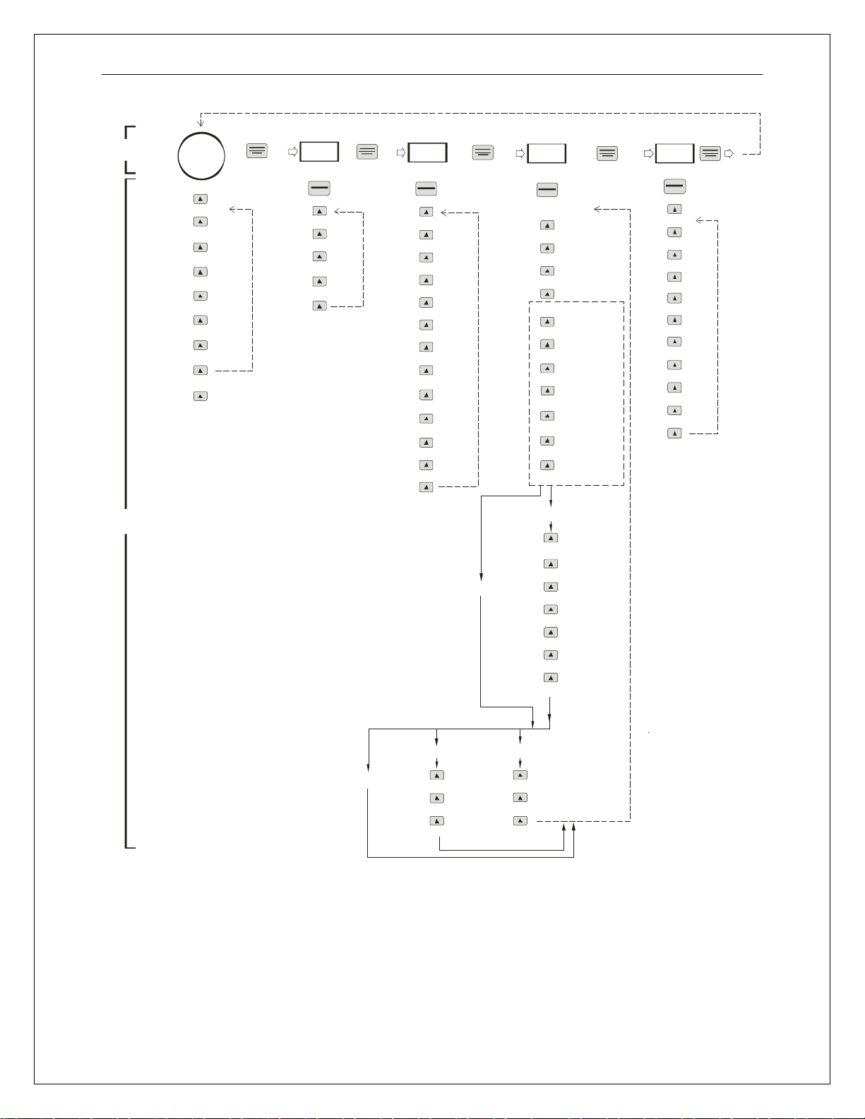
OMEGA CDTX-45 Conductivity System Part 5 – Configuration
MENU
SECTIONS
LIST
ITEMS
Start
MEASURE
(display only)
Temperature
* PID % Output
Loop Current #1
Loop Current #2
Slope
TDS
Model /Software Ver
** Autocleaner Status
CAL
or
Cal Cond.
Cal Temp
Set Range
Cal Zeros
CONFIG
or
Entry Lock
Set Delay
Contrast
Main Display
Solu Comp
Ref Temp
TDS Factor
Out1 Mode
Out2 Mode
Relay A Mode
Relay B Mode
Temp Units
CONTROL
or
Set 4mA (#1)
Set 20mA (#1)
Set 4mA (#2)
Set 20mA (#2)
Setpnt A
Hyst A
Delay A
Phase A
Setpnt B
Hyst B
Delay B
Phase B
If Relay A= AL
Setpnt A- HI
If Rly A &
B are set to
, these
CON
are the
program
steps, if
Rlys are
set to
something
other than
, see
CON
steps below
DIAG
or
Set Hold
Fault List
Sim Out
* PID Timer
Fail Out #1
Fail Val #1
Fail Out #2
Fail Val #2
Failsafe
Set Default
Figure 5-2 Software Map
If Relay B= FAIL
If Relay A= FAIL
If Relay B= Cln2
Timer Clean
Timer Cycle
Timer Hold
Hyst A- HI
Delay A- HI
Setpnt A- LO
Hyst A- LO
Delay A- LO
Phase A
If Relay B= CLn1
Timer Clean
Timer Cycle
Timer Hold
* Functions enabled with
Relay Option Card
** If Rly B is set to Cln1
or Cln2
- 32 -
Page 34

OMEGA CDTX-45 Conductivity System Part 5 – Configuration
5.22 Measure Menu [MEASURE]
The default menu for the system is the display-only menu MEASURE.
This menu is a display-only measurement menu, and has no changeable
list items. When left alone, the instrument will automatically return to this
menu after approximately 30 minutes. While in the default menu, the UP
arrow allows the user to scroll through the secondary variables on the
lower line of the display. A brief description of the fields in the basic
transmitter version is as follows:
TRANSMITTER MEAS SCREENS:
25.7°C Temperature display. Can be displayed in °C or °F,
depending on user selection. A small “m” on the left side of
the screen indicates the transmitter has automatically
jumped to a manual 25°C setting due to a failure with the
temperature signal input.
100% 20.00 mA PID Status screen (if enabled.) Shows the present controller
output level on left, and actual transmitter current on the
right. The controller can be placed in manual while viewing
this screen by pressing and holding the ENTER key for 5
seconds until a small flashing “m” appears on the screen. At
that point the controller output can be adjusted up or down
using the UP and LEFT arrow keys. To return to automatic
operation, press and hold the ENTER key for 5 seconds and
the “M” will disappear.
Loop Current #1 Indicates current output setting on TB1
Loop Current #2 Indicates current output setting on TB2
Cell Const This function allows the user to directly enter the factory
measured cell constant for the CDTX-45 sensor. When this
feature is used, calibration with reference solutions is
unnecessary. See Part 5 - Calibration for more details.
TDS = 200 ppm Total Dissolved Solids (TDS). Displays TDS of process.
Q45C2 v4.00 Transmitter software version number.
Note: A display test (all segments ON) can be actuated by pressing and
holding the ENTER key while viewing the model/version number on
the lower line of the display.
- 33 -
Page 35

OMEGA CDTX-45 Conductivity System Part 5 – Configuration
For the relay-based analyzer version, or the portable battery powered version of
the transmitter, the screens are basically the same, with additions to show two
analog outputs instead of one (#1 and #2.)
The MEASURE screens are intended to be used as a very quick means of
looking up critical values during operation or troubleshooting.
5.23 Calibration Menu [CAL]
The calibration menu contains items for frequent calibration of user
parameters. There are five items in this list: Cal Cond, Cell Temp, Cal
Const, and Cal Zeros.
Cal Cond The conductivity calibration function allows the user to adjust
the transmitter offset and span reading to match reference
buffers, or to adjust the sensor offset to match the sample
reading. See Part 7 - Calibration for more details.
Cal Temp The temperature calibration function allows the user to
adjust the offset of the temperature response by a small
factor of ±5 °C. The temperature input is factory calibrated
to very high accuracy. However, long cable lengths and
junction boxes may degrade the accuracy of the temperature
measurement in some extreme situations. Therefore, this
feature is provided as an adjustment. See Part 7 Calibration for more details.
Cell Const This function allows the user to directly enter the factory
measured cell constant for the CDTX-45 sensor. When this
feature is used, calibration with reference solutions is not
necessary. See Part 7 - Calibration for more details.
Set Range This function allows the user to set the display range of the
transmitter for a specific application. Once set, all output
functions use this display range to establish configuration
settings. Press ENTER to initiate user entry mode, and the
value will flash. Use the arrow key to modify the range for
the desired range and then press ENTER.
Cal Zeros This function calibrates all range zero-points to the specific
sensor being used. This function is only required to be
performed once at initial start-up or when the sensor has
been replaced. See Part 7 - Calibration for more details.
- 34 -
Page 36

OMEGA CDTX-45 Conductivity System Part 5 – Configuration
5.24 Configuration Menu [CONFIG]
The Configuration Menu contains all of the general user
settings:
Entry Lock This function allows the user to lock out unauthorized
tampering with instrument settings. All settings may be
viewed while the instrument is locked, but they cannot be
modified. The Entry Lock feature is a toggle-type setting;
that is, entering the correct code will lock the transmitter and
entering the correct code again will unlock it. The code is
preset at a fixed value. Press ENTER to initiate user entry
mode and the first digit will flash. Use arrow keys to modify
value. See end of manual for the CDTX-45 lock/unlock
code. Press ENTER to toggle lock setting once code is
correct. Incorrect codes do not change state of lock
condition.
Set Delay The delay function sets the amount of damping on the
instrument. This function allows the user to apply a first
order time delay function to the conductivity measurements
being made. Both the display and the output value are
affected by the degree of damping. Functions such as
calibration are not affected by this parameter. The
calibration routines contain their own filtering and stability
monitoring functions to minimize the calibration timing.
Press ENTER to initiate user entry mode, and the value will
flash. Use the arrow keys to modify value; range is 0.1 to
9.9 minutes. Press ENTER to store the new value.
Contrast This function sets the contrast level for the display. The
custom display is designed with a wide temperature range,
Super-Twist Nematic (STN) fluid.
The STN display provides the highest possible contrast and
widest viewing angle under all conditions. Contrast control
of this type of display is generally not necessary, so contrast
control is provided as a means for possible adjustment due
to aging at extreme ranges. In addition, the display has an
automatic temperature compensation network. Press
ENTER to initiate user entry mode, and the value will flash.
Use arrow keys to modify the value; range is 0 to 8 (0 being
lightest). Press ENTER to update and store the new value.
- 35 -
Page 37

OMEGA CDTX-45 Conductivity System Part 5 – Configuration
Main Display This function allows the user to change the measurement in
the primary display area. The user may select between
conductivity, sensor temperature, or output current. Using
this function, the user may choose to put temperature in the
main display area and conductivity on the secondary, lower
line of the display. Press ENTER to initiate user entry mode,
and the entire value will flash. Use the UP arrow key to
modify the desired display value. Press ENTER to store the
new value.
Select TC This function allows the user to select either a Pt1000 or
Pt100 platinum RTD temperature element. The Pt1000
element is the standard element in all high performance
CDTX-45 sensors; it is the recommended temperature
sensing element for all measurements. The Pt100 selection
is provided as an alternative for use with existing
combination-style sensors. Press ENTER to initiate user
entry mode, and the entire value will flash. Use the UP
arrow key to modify the desired value. Press ENTER to
store the new value.
Temp Mode This function sets the temperature compensation algorithm
for the instrument. The following choices are available: Lin,
1 Tbl, and 2 Tbl.
Lin: Linear temperature compensation method. This is the
most common method and is recommended for most
aqueous solutions. The slope for this method is set in
the Linear Comp section.
1 Tbl: Ammonia compensation method. This method is
specific only to ammonia measurement.
2 Tbl: Natural Water compensation method. This setting is
limited to the temperature range of 0 - 35 °C.
NOTES: 1. Do not set the Temp Mode to a value
other than Lin unless the instrument is
specifically intended to measure one of
the compounds listed above.
2. If Temp Mode is set to 1 Tbl or 2 Tbl,
the settings for Linear Comp and Ref
Temp will not appear in the Software
Menu.
- 36 -
Page 38

OMEGA CDTX-45 Conductivity System Part 5 – Configuration
This selection is critical for control of the internal diagnostics
and compensation factors. Press ENTER to initiate user
entry mode, and the entire value will flash. Use the UP
arrow key to modify the desired value.
Solu Comp This function sets the correction slope value for the linear
temperature compensation method and is used when the
“Temp Mode” is set to Lin. Linear compensation is the
method recommended for most aqueous solutions, and the
value is typically 2.00 %/°C (25°C reference temperature) for
neutral water. This is the factory default and it provides the
best compensation for most aqueous solutions. Other
typical ranges include:
Acids: 1.0 to 1.6%/°C
Bases: 1.8 to 2.0%/°C
Salts: 2.2 to 3.0%/°C
NOTE: If the temperature units are changed between
°C and °F (see Temp Units in this Section), the
default setting for this output will change
between 2.00 %/°C and 1.11%/°F accordingly.
Other compensation slopes for uncommon solutions may be
found in chemical handbooks (such as the CRC). Press
ENTER to initiate user entry mode, and the entire value will
flash. Use the arrow keys to modify the desired value; entry
range is 0.000%/°C (no compensation) to 4.000%/°C. Press
ENTER to store the new value.
Ref Temp The reference temperature function sets the basis point for
the linear temperature compensation methods. In most
cases this setting should be left at the default of 25.0 °C.
Press ENTER to initiate user entry mode, and the entire
value will flash. Use the arrow keys to modify the desired
value; range is 0.0°C to 50.0°C. Press ENTER to update
and store the new value. This setting appears in the
Software Menu only if “Temp Mode” is set to Lin.
TDS Factor This function sets the linear relationship of the TDS (total
dissolved solids) reading to the conductivity measurement.
The actual units for the slope are in mg/L/μS. The default
value is 00.49 mg/L/μS.
Press ENTER to initiate user entry mode, and the entire
value will flash. Use the arrow keys to modify the desired
value; range is 00.00 mg/L/μS to 99.99 mg/L/μS. Press
- 37 -
Page 39

OMEGA CDTX-45 Conductivity System Part 5 – Configuration
ENTER to update and store the new value.
Out 1 Mode This assigns the 4-20 mA output #1 to either µS (by
selecting 1) or for PID output (by selecting 2)
Out 2 Mode This assigns the 4-20 mA output # 2 to Temperature (by
selecting 1), µS (by selecting 2) or mg/L (by selecting 3)
Relay A Mode Relay A can be used in three different ways: as a setpoint
control, as a fail alarm, or as a HI-LO alarm band. The three
settings for Rly A Mode are CON, FAIL and AL.
The CON setting enables normal control operation for Relay
A, with settings for setpoint, hysteresis, delay and phasing
appearing in the CONFIG menu automatically. See Figure
5-3 for further details.
The FAIL setting enables the fail alarm mode for Relay A.
Relay A will then trip on any condition that causes the FAIL
icon to be displayed on the LCD. Using this mode allows the
User to send alarm indications to other remote devices.
The AL setting allows two setpoints to be selected for the
same relay, producing a HI-LO alarm band. In this mode,
Relay A will trip inside or outside of the band, depending
upon the Phase selected. See Figure 5-4 for further details.
Relay B Mode Relay B can be used in a number of ways: as a setpoint
control, or as an alarm. The two settings for Relay B Mode
are CON and FAIL.
The CON setting enables normal setpoint operation for
Relay B. Relay B then operates identically to Relay A, with
settings for setpoint, hysteresis, delay and phasing
appearing in the CONFIG menu automatically. See Figure
5-3 for details.
The FAIL setting enables the fail alarm mode for Relay B.
Relay B will then trip on any condition that causes the FAIL
icon to be displayed on the LCD. Using this mode allows the
User to send alarm indications to other remote devices. See
Figure 5-4 for details.
Temp Units This function sets the display units for temperature
measurement. Press ENTER to initiate user entry mode,
and the entire value will flash. Use the UP arrow key to
modify the desired display value. The choices are °F and
°C.Press ENTER to store the new value.
- 38 -
Page 40

OMEGA CDTX-45 Conductivity System Part 6 – Control
Part 6 - Control
Set 4 mA (#1)
Set 20 mA (#1) These functions set the main 4 and 20 mA current loop
output points for the transmitter. The units displayed depend
on the selection made in the CONFIG menu for I out #1
Mode. Also, when the Relay Option Board is installed, the
units will also display #1 or #2 – since there are actually two
analog outputs present in this version. Typically set 4 & 20
mA are used for conductivity.
The value stored for the 4 mA point may be higher or lower
than the value stored for the 20 mA point. The entry values
are limited to values within the range specified in “Set
Range”, and the 4 mA and the 20 mA point must be
separated by at least 1% of this range Use the LEFT arrow
key to select the first digit to be modified. Then use the UP
and LEFT arrow keys to select the desired numerical value.
Press ENTER to store the new value.
*Set 4 mA (#2)
*Set 20 mA (#2)
[temp/conductivity] These functions set the second 4 mA and 20 mA current
loop output points for the transmitter. The output may be set
to track temperature (default), or conductivity. The values
stored for the 4 mA point may be higher or lower than the
value stored for the 20 mA point.
The entry value is limited to a value between 0 and 110°C if
it is set for temperature, within the range specified in “Set
Range” if the output is set to track conductivity. The 4 mA
and the 20 mA point must be at least 20 units away from
each other. Press ENTER to initiate user entry mode, and
the value will flash. Use arrow keys to modify value. Press
ENTER to store the new value.
NOTE: If the temperature units are changed between °C and
°F (see Temp Units in this section), the default settings for
this output will be stored (present data is not converted.)
NOTE: If the battery board option is installed, the menu will
be shown as Set 0 V #2 – since the battery board has two 0-
2.5 VDC voltage output signals instead of current outputs.
- 39 -
Page 41

OMEGA CDTX-45 Conductivity System Part 6 – Control
ALARM CONFIGURATIONS APPLY TO AC POWERED UNITS ONLY
*A Setpoint This function establishes the conductivity trip point for relay
A. The entry value is limited to a value within the range
specified in “Set Range”. Use the LEFT arrow key to select
the first digit to be modified. Then use the UP and LEFT
arrow keys to select the desired numerical value. Press
ENTER to store the new value.
*A Hysteresis This function establishes the hysteresis, or “deadband”, for
Relay A. Hysteresis is most often used to control relay
chattering; however, it may also be used in control schemes
to separate the ON/OFF trip points of the relay. Press
ENTER to initiate user entry mode, and the value will flash.
Use the arrow keys to modify value. Press ENTER to store
the new value.
*A Delay This function places an additional amount of time delay on
the trip point for relay A. This delay is in addition to the main
delay setting for the controller. The entry value is limited to a
value between 0 and 999 seconds. Press ENTER to initiate
user entry mode, and the value will flash. Use arrow keys to
modify value; range is 0 to 999 seconds. Press ENTER to
store the new value.
*A Phasing This function establishes the direction of the relay trip.
When phase is HI, the relay operates in a direct mode.
Therefore, the relay energizes and the LCD indicator
illuminates when the conductivity value exceeds the
setpoint. When the phase is LO, the relay energizes and the
LCD indicator illuminates when the conductivity level drops
below the setpoint. The failsafe setting does have an
impact on this logic. The description here assumes the
failsafe setting is OFF. Press ENTER to initiate user entry
mode, and the entire value will flash. Use the UP arrow key
to modify the desired value; selections include HI for direct
operation or LO for reverse operation. Press ENTER to
store the new value.
- 40 -
Page 42
OMEGA CDTX-45 Conductivity System Part 6 – Control
*Setpnt A
-
HI
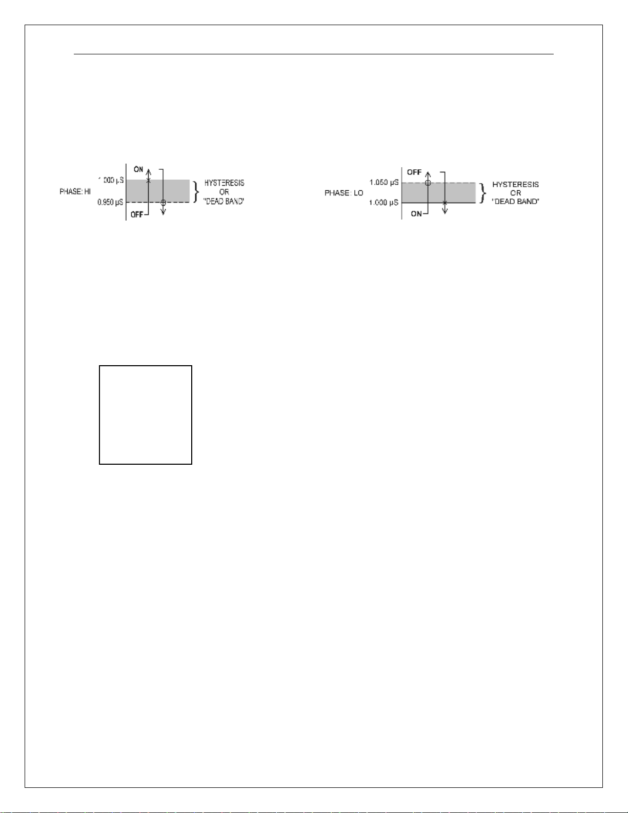
See Figure 6-1 below for a visual description of a typical control relay application.
When value rises to ≥ 1.000 µS, relay closes.
When value rises to ≥ 1.000 µS, relay opens.
Settings:
Setpoint: 1.000 µS
Hyst: 0.050
Delay: 000
Failsafe: OFF
Figure 6-1 Control Relay Example, Hysteresis and Two Opposite Phase Options
If Relay A Mode is set to Alarm Mode, AL, then the following
*Hyst A-HI
*Delay A-HI
*Setpnt A-LO
*Hyst A-LO
*Delay A-LO
settings will appear in the Config Menu list automatically. In
this mode, two setpoints can be selected on the same relay,
to create an alarm band. Phase HI selection causes the
relay to energize outside of the band, and Phase LO causes
the relay to energize inside of the band. This feature
enables one relay to be used as a control relay while the
other is used as a HI-LO Alarm relay at the same time.
Setpoint A-LO must be set lower than Setpoint A-HI. When
AL mode is first selected, Setpoint A-LO is defaulted to 0.
When value falls to ≤ 1.000 µS, relay opens.
When value falls to ≤ 1.000 µS, relay closes.
- 41 -
Page 43
OMEGA CDTX-45 Conductivity System Part 6 – Control
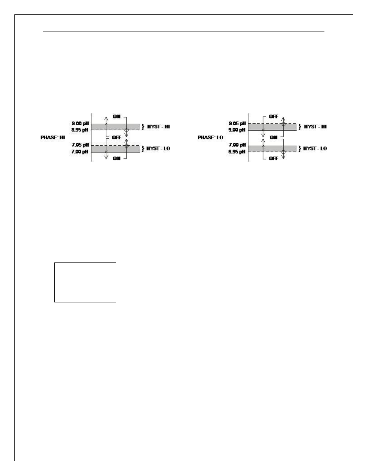
When value rises to
≥
1.000 µS, relay closes,
When value falls to
≤
1.000 µS, relay closes,
When value rises to
≥
0.500 µS, relay closes,
When value falls to
≤
0.500 µS, relay
*B Setpoint
Figure 6-2 is a visual description of a typical alarm relay application.
until value falls back to ≤ 0.950 µS.
until value rises back to ≥ 1.050 µS.
Setpoint A-HI: 1.000 µS Setpoint A-LO: 0.500 µS
Hyst A-HI: 0.050 Hyst A-LO: 0.05
Delay A-HI: 000 Delay A-LO: 000
Settings:
Figure 6-2 Alarm Relay Example
If Relay B Mode is set to CON (see Relay B Mode), then
*B Hysteresis
*B Delay
*B Phasing
Relay B will function identically to Relay A. Relay B settings
appear in the CONFIG menu list automatically.
closes, until value rises back to ≥ 0.550 µS.
until value falls back to ≤ 0.450 µS.
- 42 -
Page 44

OMEGA CDTX-45 Conductivity System Part 7 – Calibration
Part 7 – Calibration
7.1 Overview and Methods
Calibration of the CDTX-45 is required to accurately match the sensor
characteristics to the monitor/analyzer. Since the output of the conductivity
sensor does not degrade over time, it is typically only required that the sensor be
calibrated at initial installation and then cleaned periodically to maintain proper
system accuracy.
It is important for the user to establish a periodic cleaning and calibration-check
schedule for sensor maintenance to maintain high system accuracy. Since the
conductivity of a solution is greatly affected by temperature, proper settings for
thermal compensation are critical for accurate operation. Before calibrating the
instrument for the very first time, it is important to select the proper operating
parameters in the configuration menus for temperature compensation methods.
Also at initial installation, a temperature calibration must be performed before
conductivity can be calibrated.
When using conductivity calibration standards for a wet calibration, take care not
to inadvertently contaminate the reference solution; always thoroughly clean the
sensor, rinsing off in tap water, and then finish rinsing in pure or de-ionized
water. In addition, note that calibration solutions less than 200 μS or greater than
100 mS can be very unstable. Moving the sensor back and forth between
different value conductivity reference solutions can quickly contaminate the
solutions and render them inaccurate.
7.11 1-Point Calibration Explained
The 1-point calibration method is generally known as the "grab sample"
calibration method. In the 1-point calibration method, the sensor may be
removed from the application and placed into a reference solution. It may
also be left in the measurement process and calibrated by reference. The
1-point calibration adjusts the sensor slope to match the exact calibration
point. Readings beyond that point are then extrapolated from the
determined slope of the calibration line. Since the sensor slope does not
degrade over time, frequent re-calibration is unnecessary. Calibration
accuracy can be optimized by calibrating with a reference solution which is
close to the values typically measured.
7.12 Zero Cal Calibration Explained
The sensor offset must be set for the system only on initial sensor
installation, or when the cable length has been altered. The Zero Cal
method establishes all the sensor offset points for the instrument’s 6
ranges of operation.
- 43 -
Page 45

OMEGA CDTX-45 Conductivity System Part 7 – Calibration
7.2 Performing a Sensor Zero Calibration
The sensor offset MUST be set for the system on initial sensor installation, or
when the cable length has been altered. However, it can easily be adjusted at
any time by re-calibrating the sensor in air. The sensor zero-calibration generally
has little effect in measurements above about 50 mS, but it can have a significant
effect in measurements below about 1 mS. If the sensor zero cal is to be
performed, it must be done BEFORE the 1-point reference calibration.
To begin the sensor zero cal, verify that the sensor is connected and clean and
dry. It should be placed in the air with the electrodes at least 1 foot away from
any nearby objects. Holding it is not recommended – place on table or just hang.
Procedure
1. Remove sensor from process and clean thoroughly. Dry sensor and position
on table or hang in air (in air is best.) If on table, let end of sensor hang over
edge of table.
2. Scroll to the CAL menu section using the MENU key and press ENTER or the
UP arrow key. Scroll to the menu Zero Cal.
3. Press the ENTER key. The screen will prompt the user to position the sensor
in air.
4. Press the ENTER key. The screen will automatically scroll through all ranges
and establish and store the proper zero points.
7.3 Performing a 1-Point Calibration
This calibration method is intended to be used as an on-line calibration method
or a wet-cal with reference solutions. During calibration, the system will display
the current conductivity reading, and the user can manually enter a reference
value from a reference solution bottle or a comparative reference instrument.
For wet calibrations, the user may use pre-made calibration references or a NaCl
solution may be made using pure, dried NaCl crystals and one liter of high purity,
de-ionized, CO2-free water as mixed in the table shown in Figure 7-1. All table
data is at 25°C - therefore, the sensor must be at this temperature to calibrate
properly using the table data. If another reference calibration solution is being
used, be sure to note temperature of reference solution before calibration. Since
the sensor must ideally be at the specified temperature, wet calibrations can be
difficult to perform accurately.
- 44 -
Page 46
OMEGA CDTX-45 Conductivity System Part 7 – Calibration
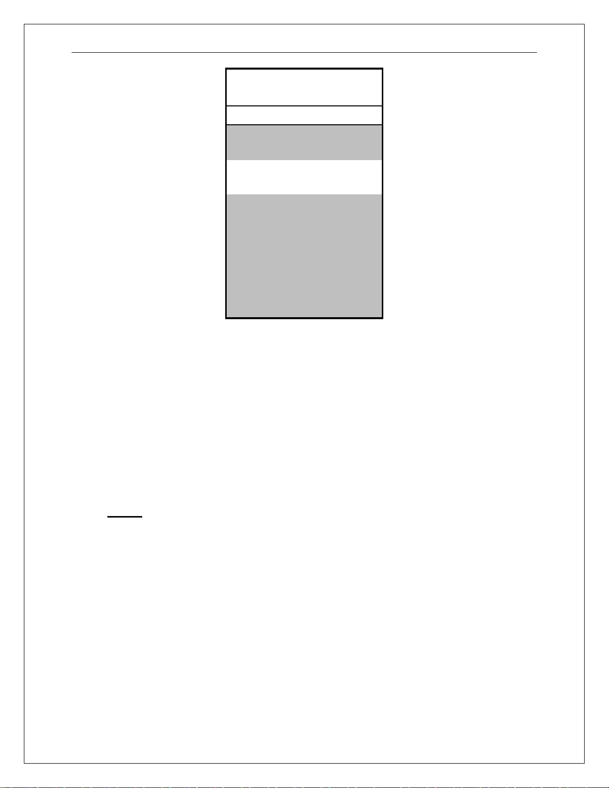
NaCl Reference Solution
μ
S/cm
NaCl (gm)
for Calibration (25°C)
100
200
500
1000
2000
3000
4000
5000
8000
10000
20000
0.05
0.10
0.25
0.50
1.01
1.53
2.06
2.61
4.34
5.56
11.59
Figure 7-1 NaCl Reference Solution for Calibration
During the 1-point calibration, the system will automatically pick the correct range
for the calibration reference if the CDTX-45 is in the AUTO range (see Section
7.11). If the CDTX-45 is in a normal display mode, the user must be careful to
calibrate with a solution that falls into the manual range selected. If the
calibration solution is outside the manual range, an error will result.
Procedure
1. If a zero calibration on the sensor is also to be performed, that must be done
FIRST. The zero calibration process can have an impact on the result of the 1point calibration. So if a zero cal is required, do that procedure and return here.
2. Determine whether the calibration will be done on-line or with the sensor
removed and placed into a reference solution. If the sensor is removed from the
application, rinse and clean. When calibrating a sensor in a beaker of reference
solution, there must be plenty of clearance between the sensor and any nearby
objects – at least 2 inches. Also, gently stir sensor back and forth to remove any
bubbles that may be present in the inner bore.
3. If the sensor has been removed and placed into a solution, allow the sensor to
temperature equilibrate with the solution as much as possible. With the sensor
coming from an application that differs greatly in temperature, the user may have
to wait as much as 20 minutes. If the sensor is on-line, the user may want to set
the output HOLD feature prior to calibration to lock out any output fluctuations.
- 45 -
Page 47

OMEGA CDTX-45 Conductivity System Part 7 – Calibration
4. Scroll to the CAL menu section using the MENU key and press ENTER or the UP
arrow key. Scroll until Cal Cond is displayed. Press ENTER.
5. The screen will prompt the user to place the sensor into the reference solution
(ideally this has already been done to achieve temperature equilibrium.) Once
sensor is ready, press ENTER.
6. The system now begins acquiring data for the calibration value. As data is
gathered, the units for conductivity and temperature may flash. Flashing units
indicate that this parameter is unstable. The calibration data point acquisition will
stop only when the data remains stable for a pre-determined amount of time.
This can be overridden by pressing ENTER. If the data remains unstable for 10
minutes, the calibration will fail and the message Cal Unstable will be displayed.
7. The screen will display the last measured conductivity value and a message will
be displayed prompting the user for the reference value. The user must then
modify the screen value with the arrow keys and press ENTER. The system then
performs the proper checks.
8. If accepted, the screen will display the message PASS with the slope value, then
it will return to the main measurement display. If the calibration fails, a message
indicating the cause of the failure will be displayed and the FAIL icon will be
turned on.
7.4 Temperature Calibration
The temperature input is factory calibrated for the highest accuracy.
Temperature calibration is not recommended; however, it is provided for
applications in which very long cable lengths are needed. For example, at 50
feet, readings may be off ±0.2 °C.
The temperature calibration sequence is essentially a 1-point offset calibration
that allows adjustments of approximately ±5 °C.
The sensor temperature may be calibrated on line, or the sensor can be removed
from the process and placed into a known solution temperature reference. In any
case, it is critical that the sensor be allowed to reach temperature equilibrium with
the solution in order to provide the highest accuracy.
When moving the sensor between widely different temperature conditions, it may
be necessary to allow the sensor to stabilize as much as one hour before the
calibration sequence is initiated. If the sensor is on-line, the user may want to set
the output HOLD (see Section 5.26) feature prior to calibration to lock out any
output fluctuations.
Procedure
- 46 -
Page 48

OMEGA CDTX-45 Conductivity System Part 7 – Calibration
1. Scroll to the CAL menu section using the MENU key and press ENTER or the
UP arrow key.
2. Press the UP arrow key until Cal Temp is displayed.
3. Press the ENTER key. The message Place sensor in solution then press
ENTER will be displayed. Move the sensor into the calibration reference (if it
hasn’t been moved already) and wait for temperature equilibrium to be
achieved. Press ENTER to begin the calibration sequence.
4. The calibration data gathering process will begin. The message Wait will
flash as data is accumulated and analyzed. The °C or °F symbol may flash
periodically if the reading is too unstable.
5. The message Adjust temp value then press ENTER will be displayed, and
the right-most digit will begin to flash, indicating that the value can be
modified. Using the UP and LEFT arrow keys, modify the value to the known
ref solution temperature. Adjustments up to ± 5 °C from the factory calibrated
temperature are allowed. Press ENTER.
6. Once completed, the display will indicate PASS or FAIL. If the unit fails, the
temperature adjustment may be out of range, the sensor may not have
achieved complete temperature equilibrium, or there may be a problem with
the temperature element. In the event of calibration failure, it is
recommended to attempt the calibration again immediately.
- 47 -
Page 49

OMEGA CDTX-45 Conductivity System Part 8 – PID Controller Details
Part 8 – PID Controller Details
8.1 PID Description
PID control, like many other control schemes, are used in chemical control to
improve the efficiency of chemical addition or control. By properly tuning the
control loop that controls chemical addition, only the amount of chemical that is
truly required is added to the system, saving money. The savings can be
substantial when compared to a system which may be simply adding chemical at
a constant rate to maintain some minimal addition under even the worst case
conditions. The PID output controller is highly advantageous over simple control
schemes that just utilize direct (proportional only) 4-20 mA output connections for
control, since the PID controller can automatically adjust the “rate” of recovery
based on the error between the setpoint and the measured value – which can be
a substantial efficiency improvement..
The PID controller is basically designed to provide a “servo” action on the 4-20
mA output to control a process. If the user requires that a measured process
stay as close as possible to a specific setpoint value, the controller output will
change from 0% to 100% in an effort to keep the process at the setpoint. To
affect this control, the controller must be used with properly selected control
elements (valves, proper chemicals, etc.) that enable the controller to add or
subtract chemical rapidly enough. This is not only specific to pumps and valves,
but also to line sizes, delays in the system, etc.
This section is included to give a brief description of tuning details for the PID
controller, and is not intended to be an exhaustive analysis of the complexities of
PID loop tuning. Numerous sources are available for specialized methods of
tuning that are appropriate for a specific application.
8.2 PID Algorithm
As most users of PID controllers realize, the terminology for the actual algorithm
terms and even the algorithms themselves can vary between different
manufacturers. This is important to recognize as early as possible, since just
plugging in similar values from one controller into another can result in
dramatically different results. There are various basic forms of PID algorithms
that are commonly seen, and the implementation here is the most common
version; The ISA algorithm (commonly referred to as the “ideal” algorithm.)
- 48 -
Page 50

OMEGA CDTX-45 Conductivity System Part 8 – PID Controller Details
tde
dt
)(
1
tePoutput
)(
∫
I
Where:
output = controller output
P = proportional gain
I = integral gain
D = derivative gain
t = time
e(t) = controller error (e=measured variable – setpoint)
Figure 8-1 (Ideal) PID Equation
The most notable feature of the algorithm is the fact the proportional gain term
affects all components directly (unlike some other algorithms - like the “series”
form.) If a pre-existing controller utilizes the same form of the algorithm shown
above, it is likely similar settings can for made if the units on the settings are
exactly the same. Be careful of this, as many times the units are the reciprocals
of each other (i.e. reps-per-min, sec-per-rep.)
PID stands for “proportional, integral, derivative.” These terms describe the three
elements of the complete controller action, and each contributes a specific
reaction in the control process. The PID controller is designed to be primarily
used in a “closed-loop” control scheme, where the output of the controller directly
affects the input through some control device, such as a pump, valve, etc.
Although the three components of the PID are described in the setting area
(section 4.25), here are more general descriptions of what each of the PID
elements contribute to the overall action of the controller.
P Proportional gain. With no “I” or “D” contribution, the controller output is
simply a factor of the proportional gain multiplied by the input error
(difference between the measured input and the controller setpoint.)
Because a typical chemical control loop cannot react instantaneously to a
correction signal, proportional gain is typically not efficient by itself – it
must be combined with some integral action to be useful. Set the P term to
a number between 2-4 to start. Higher numbers will cause the controller
action to be quicker.
I Integral gain. Integral gain is what allows the controller to eventually drive
the input error to zero – providing accuracy to the control loop. It must be
used to affect the accuracy in the servo action of the controller. Like
proportional gain, increasing integral gain results in the control action
happening quicker. Set the I term to a number between 3-5 to start (1-2
more than P). Like proportional gain, increasing the integral term will
cause the controller action to be quicker.
++=
Dtdte
)()(
- 49 -
Page 51

OMEGA CDTX-45 Conductivity System Part 8 – PID Controller Details
D Derivative gain. The addition of derivative control can be problematic in
many applications, because it greatly contributes to oscillatory behavior.
In inherently slow chemical control process’, differential control is
generally added in very small amounts to suppress erratic actions in the
process that are non-continuous, such as pumps and valves clicking on
and off. However, as a starting point for chemical process control, its best
to leave the “D” term set to 0.
Based on these descriptions, the focus on tuning for chemical applications really
only involves adjustment of “P” and “I” in most cases. However, increasing both
increases the response of the controller. The difference is in the time of recovery.
Although combinations of high “P’s” and low “I” will appear to operate the same
as combinations of low “P’s” and high “I’s”, there will be a difference in rate of
recovery and stability. Because of the way the algorithm is structured, large “P’s”
can have a larger impact to instability, because the proportional gain term
impacts all the other terms directly. Therefore, keep proportional gain lower to
start and increase integral gain to achieve the effect required.
Many of the classical tuning techniques have the user start with all values at 0,
and then increase the P term until oscillations occur. The P value is then
reduced to ½ of the oscillatory value, and the I term is increased to give the
desired response. This can be done with the CDTX-45 controller, with the
exception that the I term should start no lower than 1.0.
If it appears that even large amounts of integral gain (>20) don’t appreciably
increase the desired response, drop I back to about 1.0, and increase P by 1.00,
and start increasing I again. In most chemical control schemes, I will be
approximately 3 times the value of P.
8.3 Classical PID Tuning
Unlike many high speed position applications where PID loops are commonly
used, the chemical feed application employed by this instrument does not require
intense mathematical exercise to determine tuning parameters for the PID. In
fact, the risk of instability is far greater with overly tuned PID control schemes. In
addition, many of the classical mathematical exercises can be damaging or
wasteful in the use of chemicals when the process is bumped with large amounts
of input error to seek a response curve. Because of this, the general adjustment
guidelines described in section 8.2 are sufficient for almost all application tuning
for this instrument. Beyond this, many sources are available for classical tuning
methods.
- 50 -
Page 52

OMEGA CDTX-45 Conductivity System Part 8 – PID Controller Details
8.4 Common PID Pitfalls
The most common problem occurring in PID control applications involves the
false belief that proper settings on only the PID controller can balance any
process to an efficient level.
Close-loop control can only be effective if all elements in the loop are properly
selected for the application, and the process behavior is properly understood.
Luckily, the nature of simple chemical control process’ are generally slow in
nature. Therefore, even a de-tuned controller (one that responds somewhat
slow) can still provide substantial improvements to setpoint control. In fact,
damaging oscillatory behavior is far more likely in tightly tuned controllers where
the user attempted to increase response too much.
When deciding on a PID control scheme, it is important to initially review all
elements of the process. Sticking valves, undersized pumps, or delays in
reaction times associated with chemical addition can have a dramatic effect on
the stability of the control loop. When controlling a chemical mix or reaction, the
sensor should be placed in a location that ensures proper mixing or reaction time
has occurred.
The easiest processes to control with closed-loop schemes are generally linear,
and symmetrical, in nature. For example, controlling level in tank where the
opening of valve for a fixed period of time corresponds linearly to the amount that
flows into a tank. Chemical control process’ can be more problematic when the
nature of the setpoint value is non-linear relative to the input of chemical added.
For example, pH control of a process may appear linear only in a certain range of
operation, and become highly exponential at the extreme ranges of the
measuring scale. In addition, if a chemical process is not symmetrical, that
means it responds differentially to the addition and subtraction of chemical. It is
important in these applications to study steady-state impact as well as stepchange impact to process changes. In other words, once the process has
apparently been tuned under normal operating conditions, the user should
attempt to force a dramatic change to the input to study how the output reacts. If
this is difficult to do with the actual process input (the recommended method), the
user can place the control in manual at an extreme control point such as 5% or
95%, and release it in manual. The recovery should not be overly oscillatory. If
so, the loop needs to be de-tuned to deal with that condition (reduce P and/or I.)
- 51 -
Page 53

Omega CDTX-45 Conductivity System Part 8 – System Maintenance
Part 9 – System Maintenance
WARNING: EXPLOSION HAZARD - SUBSTITUTION OF COMPONENTS
MAY IMPAIR SUITABILITY FOR CLASS I, DIVISION 2.
9.1 System Checks
1. If the FAIL icon is flashing on the display, check the Fault List to determine
the cause of the failure. To access the Fault List, press the MENU/ESC key
until the DIAG menu appears. Then press the UP arrow key until the Fault
List appears. Press the ENTER key to access the Fault List, and the highest
priority fault message will be displayed. For a list of all messages and
possible causes/solutions, refer to Section 8.5.
2. In ALL environments, connect an earth ground jumper to earth terminal
connection on transmitter.
3. Perform a one-point calibration prior to sensor installation.
4. Check sensor cable color to terminal strip markings.
5. For highly unstable behavior, remove sensor from the process and measure
the process solution in a plastic beaker. If the reading now stabilizes, place
wire in beaker solution and actual process solution to determine if a ground
loop exists.
6. If the instrument 4-20 mA output is connected into other control systems,
disconnect output loop from system load and run through a handheld DMM to
monitor current. Verify that the system operates correctly in this mode first.
9.2 Instrument Checks
1. Remove sensor completely and connect 1100 Ohms from the yellow to black
sensor input leads. Make sure the unit is configured for a Pt1000 thermal
element and that the temperature is not in manual locked mode. The
temperature reading should display approximately 25 °C and the conductivity
reading should display approximately 0.0 uS.
2. With a DMM, measure the DC voltage from the white sensor lead connection
to the black sensor lead connection. With the positive DMM lead on the white
wire, the meter should read between -4.5 and -5.5 VDC.
- 52 -
Page 54
Omega CDTX-45 Conductivity System Part 8 – System Maintenance
3. For the line powered version, verify the proper line voltage power. With
power disconnected, verify continuity across the line fuse.
4. For the DC transmitter variation, verify that power supply has required voltage
based on size of resistance in current loop. Large resistive loads can reduce
available power for transmitter.
(NOTE: See sensor manual for specific sensor tests to be performed.)
9.3 Cleaning the Sensor
Keep the sensor as clean as possible for optimum measurement accuracy.
Frequency of cleaning depends upon the process solution.
Wipe the measuring end of the sensor with a fine abrasive cloth (i.e. ScotchBrite
of equiv.). Then rinse with clean water (distilled or de-ionized if possible). This
should remove most contaminate buildup.
If necessary, soak the sensor for several minutes in a mild soap solution. Use a
small, extra-soft bristle brush (such as a mushroom brush) to thoroughly clean
the electrode surfaces. If surface deposits are not completely removed after
performing this step, a dilute acid may be used to dissolve the deposits. Soak for
a few minutes, and then rinse the sensor thoroughly with clean water (distilled or
de-ionized if possible).
Note: DO NOT soak the sensor in dilute acid solution for more than 5 minutes.
WARNING: ACIDS ARE HAZARDOUS. Always wear eye and skin protection
when handling. Follow all Material Safety Data Sheet recommendations. A
hazardous chemical reaction can be created when certain acids come in contact
with process chemicals. Make this determination before cleaning with any acid,
regardless of concentration. DO NOT use Hydrochloric Acid on any stainless
steel portion of the sensor.
After cleaning the sensor, check measurement and re-calibrate the sensor.
- 53 -
Page 55
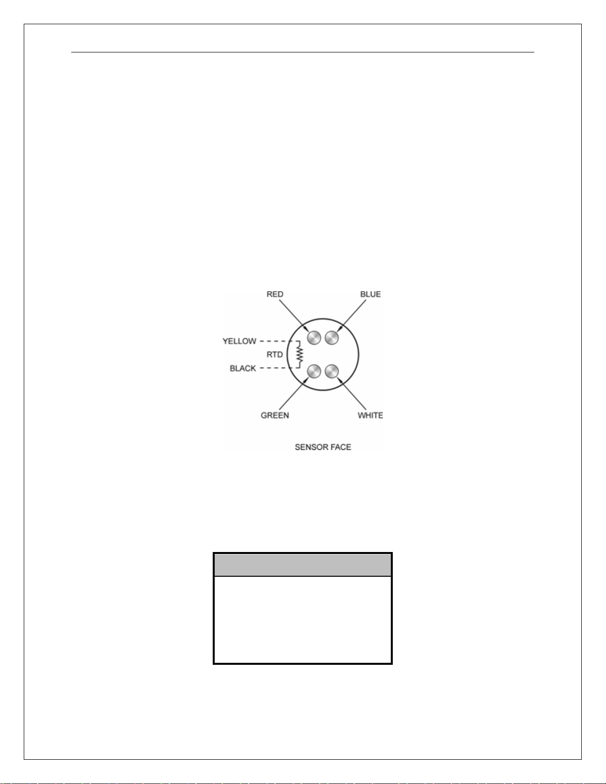
Omega CDTX-45 Conductivity System Part 8 – System Maintenance
º
C RTD
Ω
25
30
35
9.4 Troubleshooting
The first step in resolving any measurement problem is to determine whether the
trouble lies in the sensor or the transmitter. Since measurement problems can
often be traced to surface deposits coating the electrodes, cleaning the sensor
using the method outlined in Section 9.3 should always be the first step in any
troubleshooting.
If the sensor cannot be calibrated after cleaning, perform the following test. A
multimeter will be needed.
1. Disconnect the sensor from the transmitter or junction box.
2. Using a multimeter, verify continuity between electrodes indicated below and
the corresponding wire colors in the cable (red, blue, green and white, only).
3. Verify that the sensor’s temperature element (Pt1000 RTD) is functioning
properly by measuring the resistance between the sensor’s yellow and black
wires. The nominal resistance value at 25 ºC is 1097 ohms. Use the
following table as a guide to the approximate resistance value:
20
- 54 -
1078
1097
1117
1136
Page 56

Omega CDTX-45 Conductivity System Part 8 – System Maintenance
MESSAGE
DESCRIPTION
POSSIBLE CORRECTION
Max is 200
Entry failed, maximum value
Reduce value to
≤
200
Min is 200
Entry failed, minimum value allowed
Increase value to
≥
200
Cal Unstable
Calibration problem, data too
Clean sensor, get fresh cal solutions, allow
temperature and conductivity readings to fully
, do not handle sensor or cable during
Slope HIGH
Sensor slope from calibration is
Get fresh cal solutions, allow temperature and
conductivity readings to fully stabilize, check for
Slope LOW
slope from calibration is
Clean sensor, get fresh cal solutions, allow
temperature and conductivity readings to fully
Offset HIGH
Sensor offset from calibration is
n
Clean or replace saltbridge, replace reference
cell solution, clean sensor, get fresh cal
solutions, allow temperature and conductivity
readings to fully stabilize, check for correct
Out of Range
Input value is outside selected
nge of the specific list item being
Check manual for limits of the function to be
Locked!
Transmitter security setting is
Enter security code to allow modifications to
Unlocked!
en
Displayed just after security code has been
TC-F25 lock!
The TC selection is in F25 mode,
Calibration and TC adjustment cannot be
performed while the TC is in F25 mode. To
9.5 Display Messages
The CDTX-45 Series instruments provide a number of diagnostic messages that
indicate problems during normal operation and calibration. These messages
appear as prompts on the secondary line of the display or as items on the Fault
List .
The following messages will appear as prompts:
allowed is 200.
is 200.
unstable to calibrate.
stabilize
calibration.
greater than 110%.
Sensor
less than 80%.
less than –90 mV or greater tha
+90 mV
ra
configured.
locked.
Transmitter security has just be
unlocked.
locked at 25 ºC
correct buffer values
stabilize, check for correct buffer values.
buffer values.
configured.
settings.
entered.
allow access to TC calibrations, change TC
mode from F25 (fixed 25) to SENS (sensor).
The following messages will appear as items on the Fault List:
- 55 -
Page 57
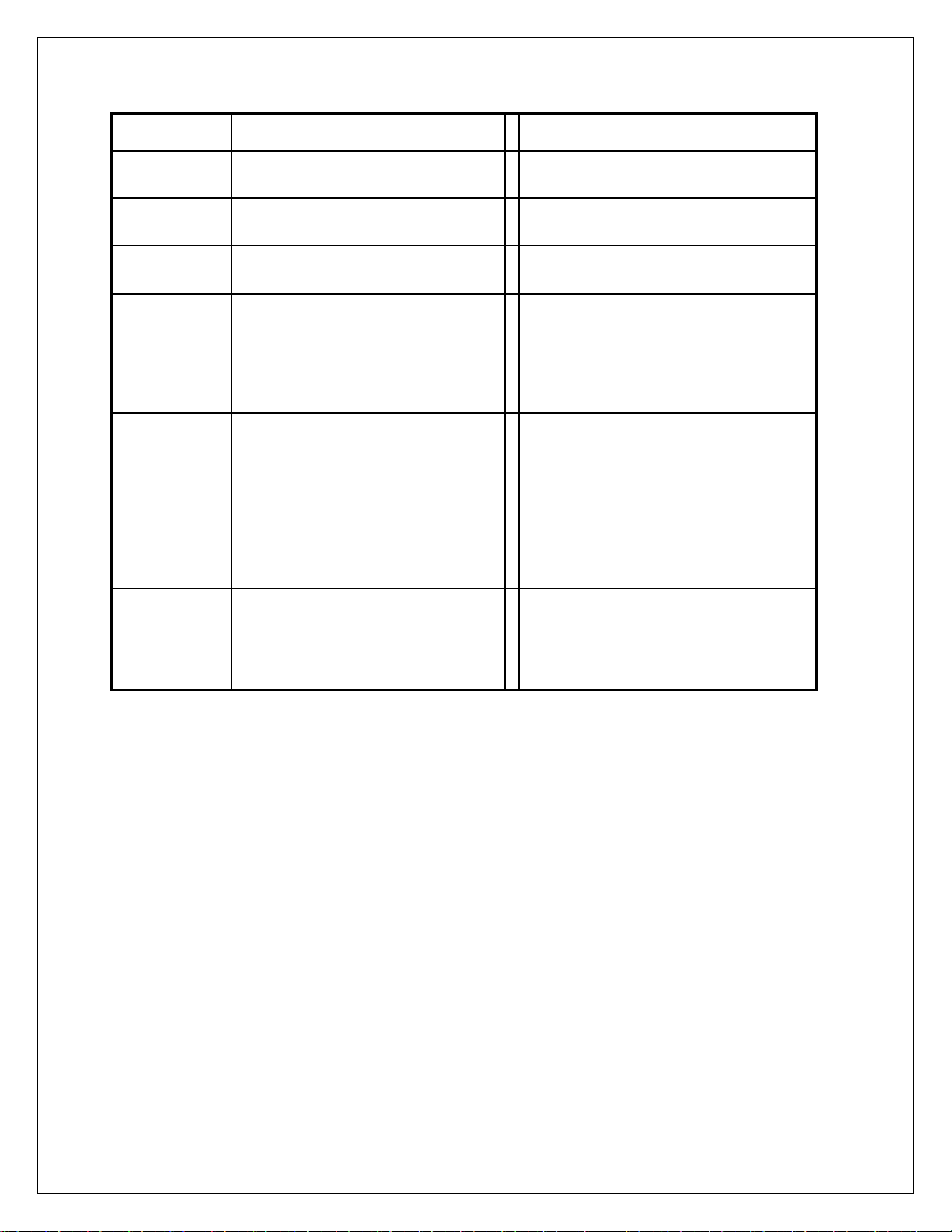
Omega CDTX-45 Conductivity System Part 8 – System Maintenance
MESSAGE
DESCRIPTION
POSSIBLE CORRECTION
Sensor High
The raw signal from the sensor is too
Sensor L
ow
The raw signal from the sensor is too
Cond too High
The conductivity reading is over operating
Temp High
ading is over operating
limits. Check wiring and expected temp
level. Perform RTD test as described in
sensor manual. Recalibrate sensor
Temp Low
The temperature reading is under
erating limits. Check wiring and
expected temp level. Perform RTD test as
described in sensor manual. Recalibrate
TC Error
Check sensor wiring and perform RTD test
Clean Sensor
have
reached the level that they cannot be
Check wiring connections to sensor.
high.
low.
Check wiring connections to sensor.
The conductivity reading is > 2000 mS.
The temperature reading is > 210 ºC.
The temperature reading is < -10 ºC
TC may be open or shorted.
Surface deposits on sensor may
adjusted out.
limits.
The temperature re
temperature element if necessary.
op
sensor temperature element if necessary.
as described in sensor manual.
Clean the sensor thoroughly.
- 56 -
Page 58
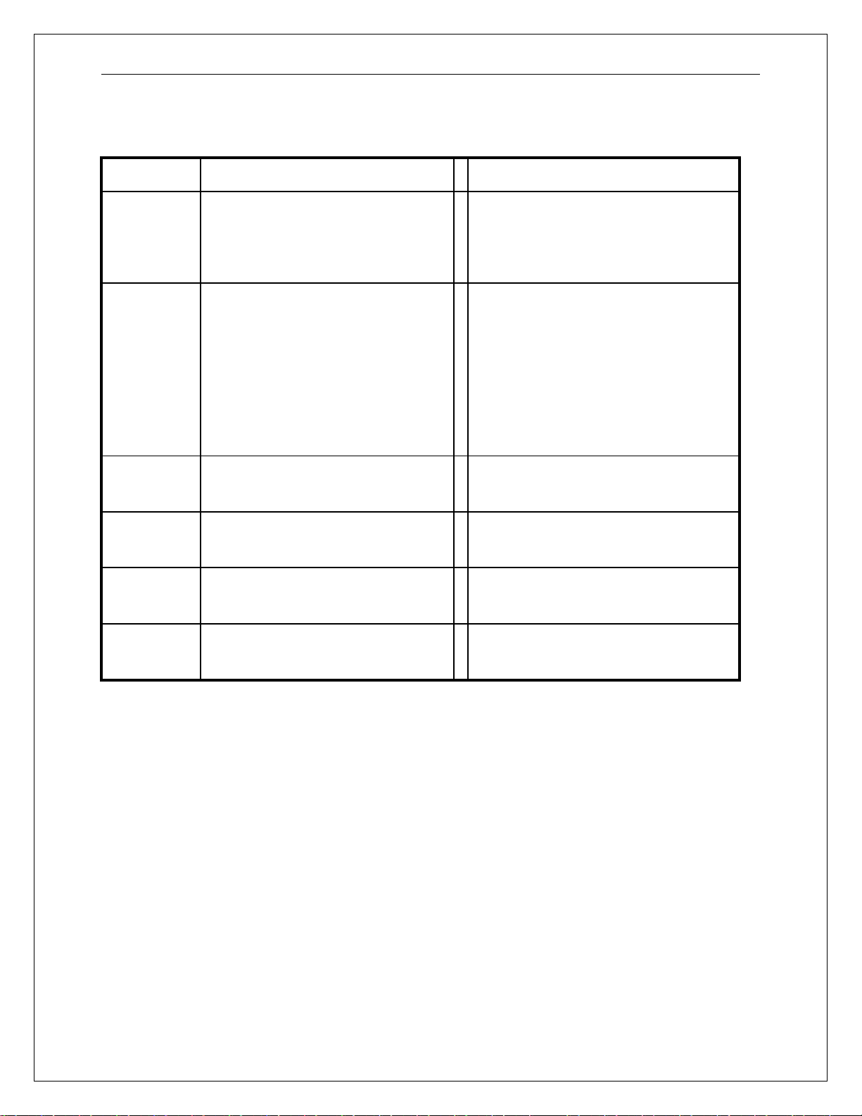
Omega CDTX-45 Conductivity System Part 8 – System Maintenance
MESSAGE
DESCRIPTION
POSSIBLE CORRECTION
Cond C
al Fail
Clean sensor, get fresh cal solutions and
redo calibration. If still failure, sensor
slope may be less than 50%. Perform
sensor tests as described in sensor
TC Cal F
ail
Clean sensor, check cal solution
temperature and repeat sensor temp
calibration. TC calibration function only
C. If still
failure, perform sensor tests as described
Replace sensor if still
failure. Note that TC offset may also be
adjusted using the Cal TC Factor function
(See Section 6.4) which involves no
EEprom Fail
Chcksum Fail
Display Fail
Range Cal
Failure of factory temperature
Fault List display messages (continued):
Failure of conductivity calibration.
Failure of temperature calibration.
Internal nonvolatile memory failure
Internal software storage error.
Internal display driver fail.
manual. Replace sensor if still failure.
allows adjustments of +/- 6 º
in sensor manual.
calibration reference solutions.
System failure, consult factory.
System failure, consult factory.
System failure, consult factory.
Fail
calibration.
Lock/Unlock Code: 1453
- 57 -
Consult factory.
Page 59

WARRANTY/DISCLAIMER
OMEGA ENGINEERING, INC. warrants this unit to be free of defects in materials and workmanship for a
period of 13 months from date of purchase. OMEGA’s WARRANTY adds an additional one (1) month
grace period to the normal one (1) year product warranty to cover handling and shipping time. This
ensures that OMEGA’s customers receive maximum coverage on each product.
If the unit malfunctions, it must be returned to the factory for evaluation. OMEGA’s Customer Service
Department will issue an Authorized Return (AR) number immediately upon phone or written request.
Upon examination by OMEGA, if the unit is found to be defective, it will be repaired or replaced at no
charge. OMEGA’s WARRANTY does not apply to defects resulting from any action of the purchaser,
including but not limited to mishandling, improper interfacing, operation outside of design limits,
improper repair, or unauthorized modification. This WARRANTY is VOID if the unit shows evidence of
having been tampered with or shows evidence of having been damaged as a result of excessive corrosion;
or current, heat, moisture or vibration; improper specification; misapplication; misuse or other operating
conditions outside of OMEGA’s control. Components in which wear is not warranted, include but are not
limited to contact points, fuses, and triacs.
OMEGA is pleased to offer suggestions on the use of its various products. However,
OMEGA neither assumes responsibility for any omissions or errors nor assumes liability for any
damages that result from the use of its products in accordance with information provided by
OMEGA, either verbal or written. OMEGA warrants only that the parts manufactured by the
company will be as specified and free of defects. OMEGA MAKES NO OTHER WARRANTIES OR
REPRESENTATIONS OF ANY KIND WHATSOEVER, EXPRESSED OR IMPLIED, EXCEPT THAT OF
TITLE, AND ALL IMPLIED WARRANTIES INCLUDING ANY WARRANTY OF MERCHANTABILITY
AND FITNESS FOR A PARTICULAR PURPOSE ARE HEREBY DISCLAIMED. LIMITATION OF
LIABILITY: The remedies of purchaser set forth herein are exclusive, and the total liability of
OMEGA with respect to this order, whether based on contract, warranty, negligence,
indemnification, strict liability or otherwise, shall not exceed the purchase price of the
co mp onent upon which liability is based. In no event shall O ME GA be liable for
consequential, incidental or special damages.
CONDITIONS: Equipment sold by OMEGA is not intended to be used, nor shall it be used: (1) as a “Basic
Component” under 10 CFR 21 (NRC), used in or with any nuclear installation or activity; or (2) in medical
applications or used on humans. Should any Product(s) be used in or with any nuclear installation or
activity, medical application, used on humans, or misused in any way, OMEGA assumes no responsibility
as set forth in our basic WARRANTY/DISCLAIMER language, and, additionally, purchaser will indemnify
OMEGA and hold OMEGA harmless from any liability or damage whatsoever arising out of the use of the
Product(s) in such a manner.
RETURN REQUESTS/INQUIRIES
Direct all warranty and repair requests/inquiries to the OMEGA Customer Service Department. BEFORE
RETURNING ANY PRODUCT(S) TO OMEGA, PURCHASER MUST OBTAIN AN AUTHORIZED RETURN
(AR ) NUM BER F ROM O MEG A’S CUSTO MER S ERVIC E DEPARTM ENT ( IN OR DER T O AVOI D
PROCESSING DELAYS). The assigned AR number should then be marked on the outside of the return
package and on any correspondence.
The purchaser is responsible for shipping charges, freight, insurance and proper packaging to prevent
breakage in transit.
FOR WARRANTY
following information available BEFORE
contacting OMEGA:
1. Purchase Order number under which the product
was PURCHASED,
2. Model and serial number of the product under
warranty, and
3. Repair instructions and/or specific problems
relative to the product.
OMEGA’s policy is to make running changes, not model changes, whenever an improvement is possible. This affords
our customers the latest in technology and engineering.
OMEGA is a registered trademark of OMEGA ENGINEERING, INC.
© Copyright 2006 OMEGA ENGINEERING, INC. All rights reserved. This document may not be copied, photocopied,
reproduced, translated, or reduced to any electronic medium or machine-readable form, in whole or in part, without the
prior written consent of OMEGA ENGINEERING, INC.
RETURNS, please have the
FOR NON-WARRANTY REPAIRS,
for current repair charges. Have the following
information available BEFORE contacting OMEGA:
1. Purchase Order number to cover the COST
of the repair,
2. Model and serial number of the product, and
3. Repair instructions and/or specific problems
relative to the product.
consult OMEGA
Page 60

Where Do I Find Everything I Needfor
ProcessMeasurementand Control?
OMEGA…OfCourse!
Shop online at omega.com
TEMPERATURE
䡺⻬
Thermocouple, RTD & Thermistor Probes, Connectors, Panels & Assemblies
䡺⻬
Wire: Thermocouple, RTD & Thermistor
䡺⻬
Calibrators & Ice Point References
䡺⻬
Recorders, Controllers & Process Monitors
䡺⻬
Infrared Pyrometers
PRESSURE, STRAIN AND FORCE
䡺⻬
Transducers & Strain Gages
䡺⻬
Load Cells & Pressure Gages
䡺⻬
Displacement Transducers
䡺⻬
Instrumentation & Accessories
FLOW/LEVEL
䡺⻬
Rotameters, Gas Mass Flowmeters & Flow Computers
䡺⻬
Air Velocity Indicators
䡺⻬
Turbine/Paddlewheel Systems
䡺⻬
Totalizers & Batch Controllers
pH/CONDUCTIVITY
䡺⻬
pH Electrodes, Testers & Accessories
䡺⻬
Benchtop/Laboratory Meters
䡺⻬
Controllers, Calibrators, Simulators & Pumps
䡺⻬
Industrial pH & Conductivity Equipment
DATA ACQUISITION
䡺⻬
Data Acquisition & Engineering Software
䡺⻬
Communications-Based Acquisition Systems
䡺⻬
Plug-in Cards for Apple, IBM & Compatibles
䡺⻬
Datalogging Systems
䡺⻬
Recorders, Printers & Plotters
HEATERS
䡺⻬
Heating Cable
䡺⻬
Cartridge & Strip Heaters
䡺⻬
Immersion & Band Heaters
䡺⻬
Flexible Heaters
䡺⻬
Laboratory Heaters
ENVIRONMENTAL
MONITORING AND CONTROL
䡺⻬
Metering & Control Instrumentation
䡺⻬
Refractometers
䡺⻬
Pumps & Tubing
䡺⻬
Air, Soil & Water Monitors
䡺⻬
Industrial Water & Wastewater Treatment
䡺⻬
pH, Conductivity & Dissolved Oxygen Instruments
M-3695/0309
 Loading...