

Page 1
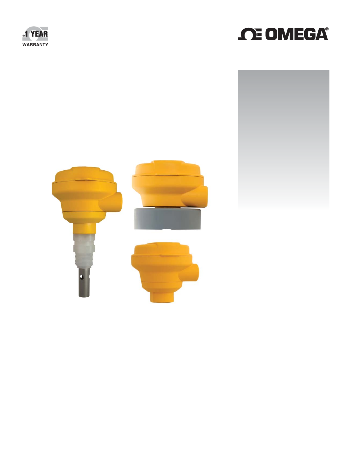
User’s Guide
Shop online at
omega.com
e-mail: [email protected]
For latest product manuals:
www.omegamanual.info
SM
CDTX-285X
Conductivity/Resistivity
Sensor Electronics
Page 2

omega.com [email protected]
Servicing North America:
U.S.A. Omega Engineering, Inc.
Headquarters: Toll-Free: 1-800-826-6342 (USA & Canada only)
Customer Service: 1-800-622-2378 (USA & Canada only)
Engineering Service: 1-800-872-9436 (USA & Canada only)
Tel: (203) 359-1660 Fax: (203) 359-7700
e-mail: [email protected]
For Other Locations Visit omega.com/worldwide
The information contained in this document is believed to be correct, but OMEGA accepts no liability for any errors it contains, and reserves
the right to alter specifications without notice.
Page 3
Contents
1. Description ................................................................. 3 9. Cell Constant Selection .............................................. 6
2. Specifi cations ............................................................. 3 10. Range Selection for 4 to 20 mA Output ...................... 7
3. CDTX-2850 Dimensions............................................. 4 11. Calibration .................................................................. 8
4. Sensor Dimensions .................................................... 4 12. EasyCal ......................................................................8
5. Operating Range Chart .............................................. 4 13. Maintenance ............................................................... 9
6. In-Line Installation ...................................................... 5 14. Troubleshooting .......................................................... 9
7. Submersible Installation ............................................. 5 15. Ordering Information ................................................10
8. Wiring 4 to 20 mA Output ........................................... 6
SAFETY PRECAUTIONS
1. Depressurize and vent system prior to installation or removal.
2. Confi rm chemical compatibility before use.
3. Do not exceed maximum temperature/pressure specifi cations.
4. Wear safety goggles or faceshield during installation/service.
5. Do not alter product construction.
6. When using chemicals or solvents, care should be taken and appropriate
eye, face, hand, body, and/or respiratory protection should be used.
1. Description
• CDTX-285X Series Conductivity/Resistivity Sensor Electronics provides either a two-wire 4 to 20 mA output.
• The 4 to 20 mA output models provide eight ranges for each electrode cell constant, plus the ability to invert each range.
• The EasyCal feature allows the devices to automatically recognize standard conductivity test solution values for simple fi eld calibration.
• The Conductivity sensor provided with integral systems will have its custom cell constant information programmed into the electronics
at the factory to provide a 2% sensor accuracy. See Section 8 for details.
2. Specifi cations
General
Compatible Electrodes ............. Omega Conductivity/Resistivity
electrodes series CDCE-90 and
CDE-285X
Temperature Compensation ..... PT-1000 RTD (2% per °C)
Pure Water Compensation ....... Auto-switching when using
0.01 cell and raw conductivity
value < 0.5 S
EasyCal:
Automatic recognition of the following conductivity values:
• 146.93 S, 1408.8 S, 12856 S (@ 25 °C)
(Test solutions per ASTM D1125-95)
• 10 S, 100 S, 200 S, 500 S, 1000 S, 5000 S,
10,000 S, 50,000 S, 100,000 S (@ 25 °C)
Electrical
Power .......................................
12 to 24 VDC (4 to 20 mA output)
(Reverse polarity and short
circuit protected)
Current Output:
Field-selectable ranges
Factory set span:
0.01 cell.................................4 to 20 mA = 0 to 100 S
0.10 cell.................................4 to 20 mA = 0 to 1000 S
1.0 cell...................................4 to 20 mA = 0 to 10,000 S
10.0 cell.................................4 to 20 mA = 0 to 200,000 S
20.0 cell.................................4 to 20 mA = 0 to 400,000 S
Max. Loop Resistance .............. 50 @ 12 VDC
325 @ 18 VDC
600 @ 24 VDC
Accuracy ................................... ±2% of output span
Resolution.................................7 A
Update Rate .............................<600 ms
Error Indication ......................... 22 mA
Environmental
Material ..................................... PBT
Enclosure Rating ...................... NEMA 4X/IP65
Operating Temperature ............. -10 °C to 85 °C
(14 °F to 185 °F)
Storage Temperature ................ -20 °C to 85 °C
(-4 °F to 185 °F)
Relative Humidity......................0 to 95%, non-condensing
Shipping Weight .......................0.75 kg (1.75 lb.)
®
3CDTX-285X Series Conductivity/Resistivity Sensor Electronics
Page 4
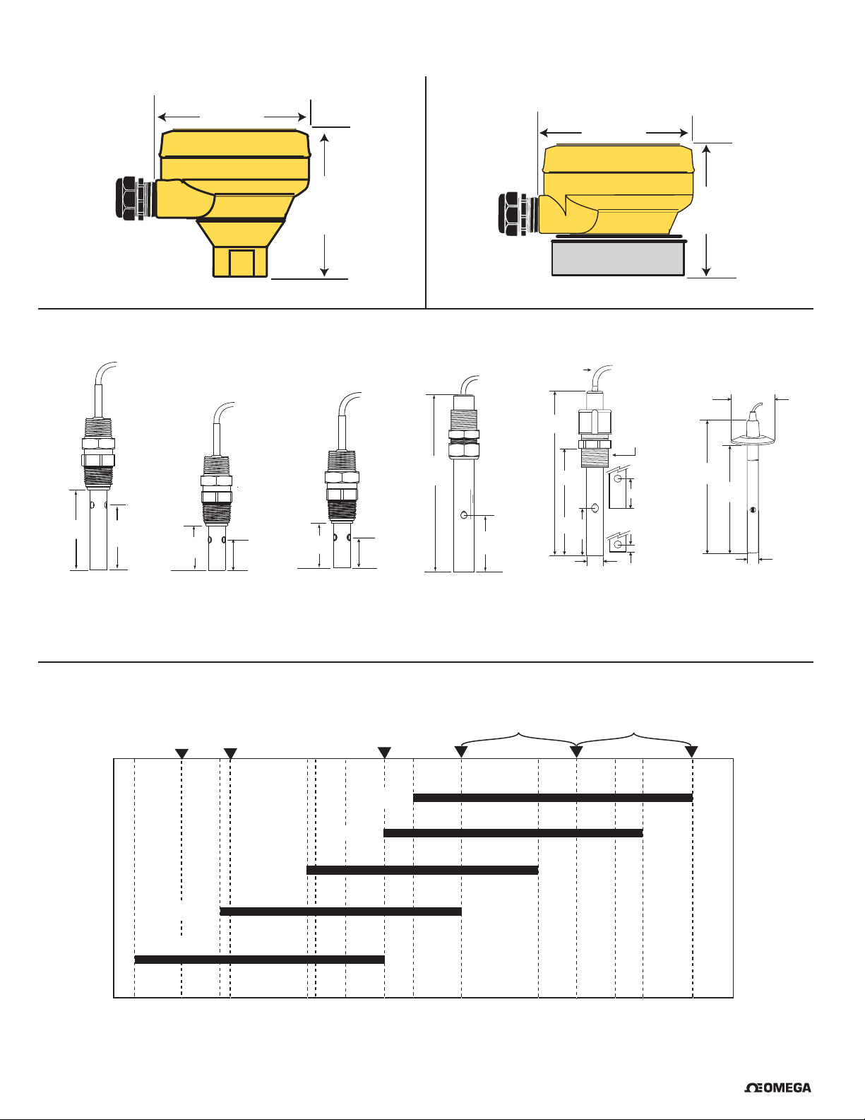
3. CDTX-2850 Dimensions
CDTX-2850-IM Integral mount
95 mm
3.74 in.
CDTX-2850-RM Universal Mount
95 mm
3.74 in.
4. Conductivity Sensor Dimensions
73.7 mm
2.90 in.
CDE-2851
CDE-2851-ISO
59.3 mm
2.33 in.
35.8 mm
1.41 in.
CDE-2852
CDE-2852-ISO
21.5 mm
0.85 in.
41.9 mm
1.65 in.
85 mm
3.34 in.
26.8 mm
1.13 in.
CDE-2853-ISO
CDE-2854
CDE-2854-ISO
203 mm
8.0 in.
CDCE-90-20BCDE-2853
89 mm
3.5 in.
4.6 m (15 ft)
cable (std)
152 mm
(6 in.)
107 mm
(4.2 in.)
49.5 mm
(1.95 in.)
12.7 mm
(0.5 in.)
CDCE-90-001
CDCE-90-01
CDCE-90-1
CDCE-90-10
¾ in. NPT
2820-x
20.3 mm
(0.8 in.)
2821-x
7.6 mm
(0.3 in.)
82 mm
3.24 in.
T1 = 50 mm (2.0 in.)
T2 = 64 mm (2.5 in.)
152 mm
(6.0 in.)
126 mm
(5.0 in.)
CDCE-90S Series
13 mm
(0.5 in.)
5. Operating Range Chart
Bottled
(20.0 Cell)
(10.0 Cell)
100 μS
50 μS
.
Water
CDCE-90-20B
CDCE-90-10 / CDE-2854
1,000 μS 10,000 μS
UPW @ 25°C
(0.1 Cell)
USP
(1.0 Cell)
CDCE-90-01 / CDE-2852
CDCE-90-1 / CDE-2853
(0.01 Cell)
CDCE-90-001 / CDE-2851
0.010 μS
0
0
1 μS
0
10 μS
.
0.5 μS 20 μS
4 CDTX-285X Series Conductivity/Resistivity Sensor Electronics
Cooling Tower
Waste Water s
Deionization Regen. Chemicals
Alkali Cleaners, Acids/Bases
50,000 μS
200,000 μS
400,000 μS 200 μS 100,000 μS 0.055 μS
®
Page 5
6. In-Line Installation
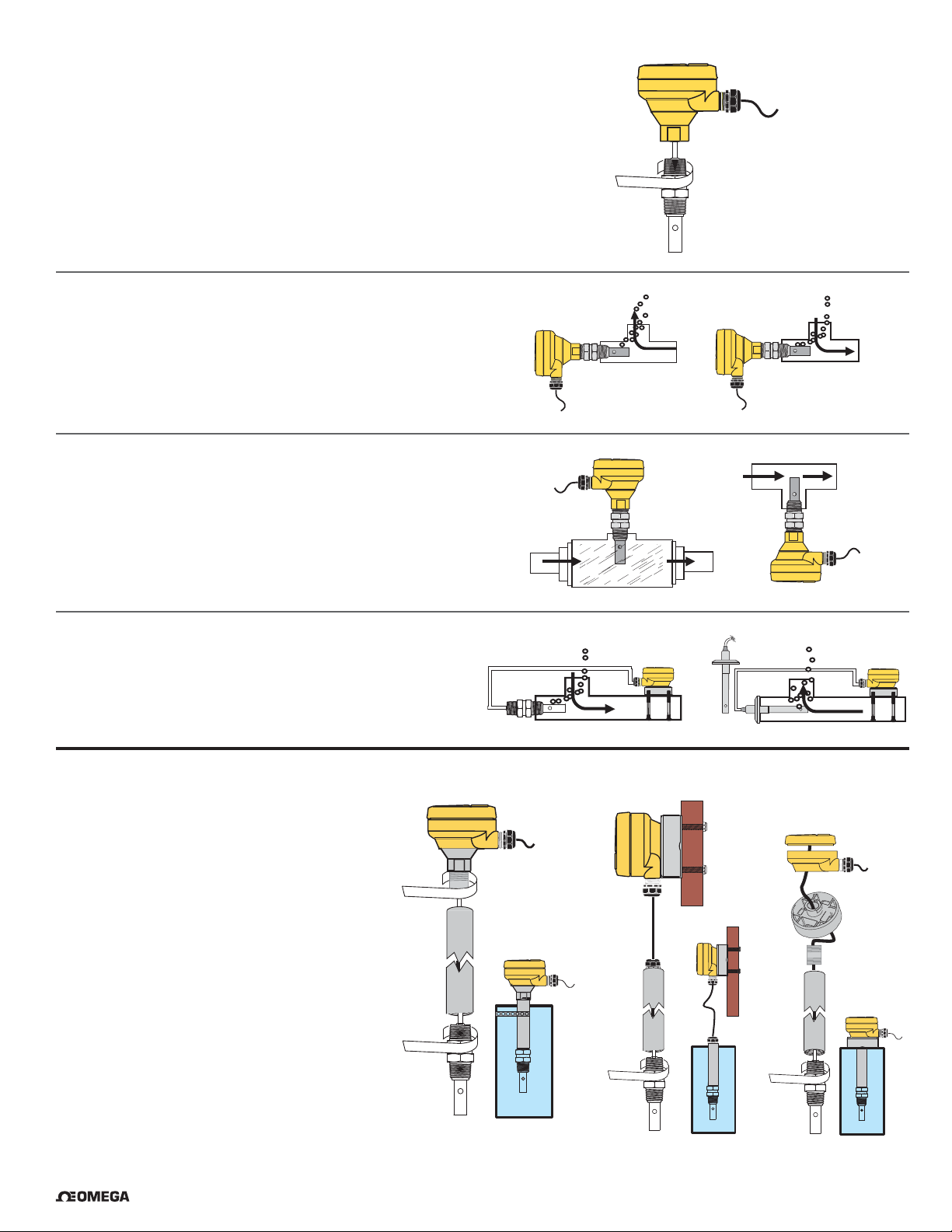
Most of the Conductivity/Resistivity electrodes used with the CDTX-285X
can be installed into standard 3/4 in. (NPT or ISO 7-R3/4) fi ttings.
The CDTX-285X models are designed for integral systems,
where the electronics are attached directly to the sensor.
The preferred installation for in-line applications directs fl ow
straight into the electrode. This confi guration reduces the
probability of entrapped air bubbles, and provides the best
continuous sampling of the fl uid content.
If the electrode is mounted vertically in a tee, do not recess the
electrode orifi ces inside the tee. Mounting upside down may help
prevent air entrapment.
An oversized tee or fl ow cell may be helpful for inline installations.
At least 4 threads (ANSI B1.20.1) must be engaged to meet the
pressure rating as published in the specifi cations.
Use the CDTX-285X-RM models for in-line installations
where the electronics must be separated from the electrode.
Conductivity electrodes with sanitary fl ange fi ttings must be
installed using this option.
7. Submersible Installation
While the CDTX-285X and CDTX-2850-RM
electronics cannot be submerged, either model
will accommodate tank installation.
Select any electrode with a 5 m (15 ft.) cable.
The cable may be cut to length,
but it CANNOT BE EXTENDED.
The universal adapter included with
CDTX-285X-RM models can be attached to the
top of a tank or mounted to a surface near the tank.
Adapt the CDTX-285X models to tank installations
by attaching a clamp to the conduit.
®
5CDTX-285X Series Conductivity/Resistivity Sensor Electronics
Page 6
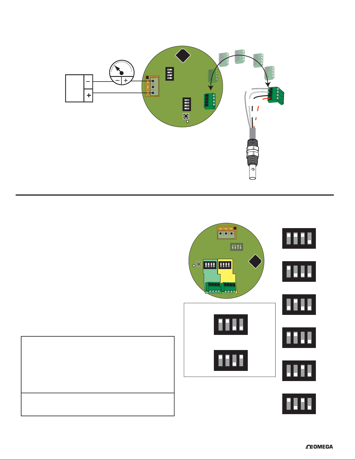
8. Wiring 4 to 20 mA Output
S
3
ONCTS
• Maximum length of 4 to 20 mA loop is 300 meters (1000 ft)
4 20
3
to
9 VDC
4-20 mA Loop Output
26 VDC
2
1
V-
V+
4
CTS
3
2
ON
1
Sensr Gnd
(SHIELD)
4
SW1
CTS
3
2
ON
1
D3
Temp. IN
(WHITE)
Signal RTN
(BLK)
Signal IN
(RED)
9. Cell Constant Selection
Cell Constant Selection
• The CDTX-285X is shipped from the factory with the custom cell
constant and temperature offset programmed into the single-input
electronics. SW3 will be preset to "Custom cell constant".
• Switch banks SW3 and SW4 are used to select the cell constant
of the electrode. The Dual Input model is illustrated. Single input
models use only SW3.
• Make all switch settings before connecting power. Switch changes
made with the power ON will take 15 to 20 seconds before
becoming effective.
• Use SW3 #1-3 to select the cell constant for the fi rst sensor.
• Use SW3 #4 to disable the PT1000 Temp Compensation function
in the CDTX-285X (as required for USP applications).
This disables the function for BOTH INPUTS.
• Use SW4 #1-3 to select the cell constant for the second sensor.
• Set SW4 #4 to OPEN to disable the second input.
SW3 Cell Constant and Temp Compensation
#1 #2 #3 #4 For Cell Constant
C C C O Custom
C O O O 0.01 cm
O C O O 0.1 cm
C C O O 1.0 cm
O O C O 10.0 cm
C O C O 20.0 cm
#4: Open = Temp Comp ON Closed = Temp Comp OFF
SW4: #1, #2 and #3 operate the same as SW3.
#4 turns input 2 OFF when set to OPEN.
(Open = Off, Closed = On)
-1
-1
-1
-1
-1
2
3
1
4
1
2
W1
CTS
CTS
ON
4
4
1
3
3
2
SW4
Ch 2
D3
ON
1
2
SW3
Ch 1
Example: 1.0 cell constant, temp comp ON
CTS
ON
1
2
Closed
Open
4
3
Example: 1.0 cell constant, temp comp OFF
CTS
ON
1
2
Closed
Open
4
3
Custom Cell Constant
CTS
ON
1
0.01/cm
ON
1
0.1/cm
ON
1
1.0/cm
ON
1
10.0/cm
ON
1
20.0/cm
ON
1
2
-1
2
-1
2
-1
2
-1
2
-1
2
Closed
Open
4
3
CTS
Closed
Open
4
3
CTS
Closed
Open
4
3
CTS
Closed
Open
4
3
CTS
Closed
Open
4
3
CTS
Closed
Open
4
3
6 CDTX-285X Series Conductivity/Resistivity Sensor Electronics
®
Page 7
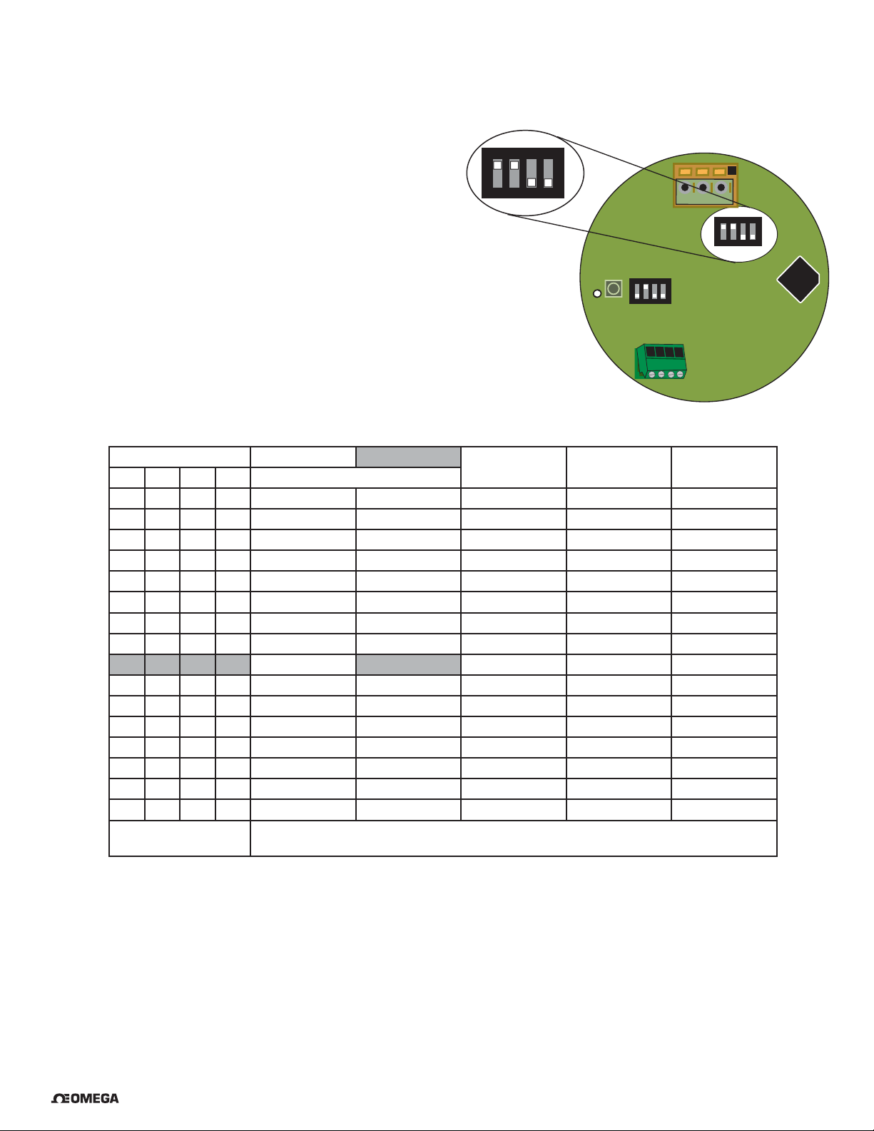
10. Range Selection for 4 to 20 mA Output
• The Range selection switch bank (SW2) provides eight range selections for each cell constant.
Each range can be inverted, making a total of 16 range options.
• Select a range from the table below and set SW2 as indicated.
CTS
ON
Example (refer to shaded selections of chart):
• The electrode installed is the CDE-2852, with a 0.10 cell constant.
• The required output is 4 to 20 mA = 0 to 100 S.
• Set SW2 switch bank to C-C-O-O.
• To invert range (4 to 20 mA = 100 to 0 S), close switch #4.
SW2 Switch Setting 0.01 Cell 0.10 Cell 1.0 Cell 10.0 Cell 20.0 Cell
#1 #2 #3 #4 Resistivity Ranges in BOLD
CCCO 10 to 20 MΩ 0 to 2 S 0 to 20 S 0 to 200 S 0 to 400 S
CCCC 20 to 10 MΩ 2 to 0 S 20 to 0 S 200 to 0 S 400 to 0 S
OCCO 2 to 10 MΩ 0 to 5 S 0 to 50 S 0 to 500 S 0 to 1000 S
OCCC 10 to 2 MΩ 5 to 0 S 50 to 0 S 500 to 0 S 1 000 to 0 S
COCO 0 to 2 MΩ 0 to 10 S 0 to 100 S 0 to 1 000 S 0 to 2 000 S
COCC 2 to 0 MΩ 10 to 0 S 100 to 0 S 1 000 to 0 S 2 000 to 0 S
O O C O 0 to 1 S 0 to 50 S 0 to 5 000 S 0 to 5 000 S 0 to 10 000 S
O O C C 1 to 0 S 50 to 0 S 500 to 0 S 5 000 to 0 S 10 000 to 0 S
C C O O 0 to 5 S 0 to 100
C C O C 5 to 0 S 100 to 0 S 1 000 to 0 S 10 000 to 0 S 20 000 to 0 S
O C O O 0 to 10 S 0 to 200 S 0 to 2 000 S 0 to 50 000 S 0 to 100 000 S
O C O C 10 to 0 S 200 to 0 S 2 000 to 0 S 50 000 to 0 S 100 000 to 0 S
C O O O 0 to 50 S 0 to 500 S 0 to 5 000 S 0 to 100 000 S 0 to 200 000 S
C O O C 50 to 0 S 500 to 0 S 5 000 to 0 S 100 000 to 0 S 200 000 to 0 S
OOOO 0 to 100 S 0 to 1 000 S 0 to 10 000 S 0 to 200 000 S 0 to 400 000 S
O O O C 100 to 0 S 1000 to 0 S 10 000 to 0 S 200 000 to 0 S 400 000 to 0 S
C = CLOSED
O = OPEN
Switch #4 inverts the output: OPEN = 4 to 20 mA, CLOSED = 20 to 4 mA
1
4
3
2
1 3 2
SW2
CTS
ON
4
1
3
C = Closed
O = Open
D3
SW1
SW3
CTS
ON
4
1
3
2
2
SW2
S 0 to 1 000 S 0 to 10 000 S 0 to 20 000 S
®
7CDTX-285X Series Conductivity/Resistivity Sensor Electronics
Page 8
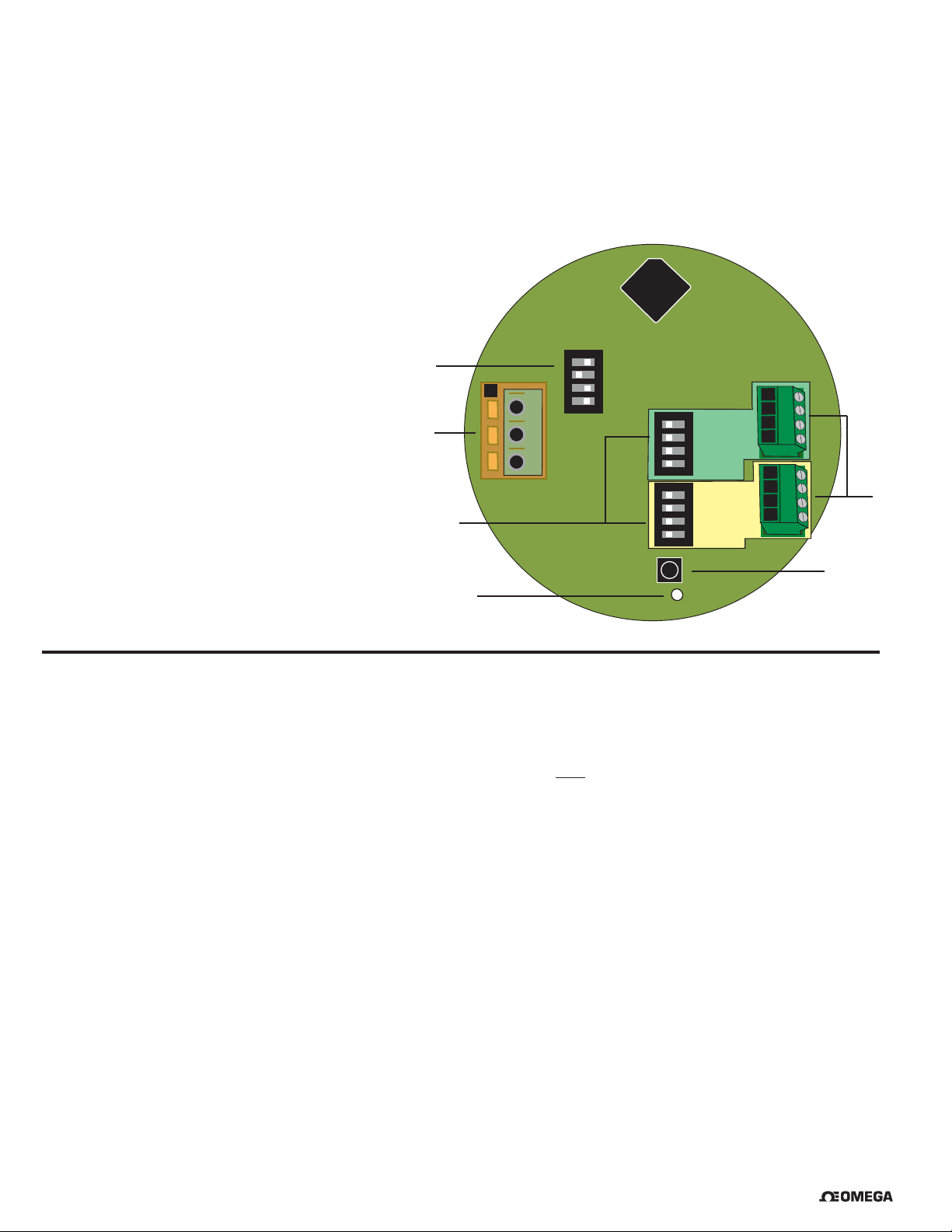
11. Calibration
• All CDTX-285X Conductivity/Resistivity Sensor Electronics are factory calibrated for maximum out-of-the-box accuracy.
• The EasyCal feature allows calibration to be performed at the sensor.
The CDE-285X Conductivity sensors come with a certifi cate of calibration. This certifi cate provides information regarding the actual
cell constant and temperature offset as tested and verifi ed according to NIST standards. This information has been programmed into
the CDTX-285X electronics as its default factory value. If required, the sensor can be recertifi ed by contacting Omega.
a. SW2: 4 to 20 mA output range selection switch bank
b. Power and 4 to 20 mA output terminal block
c. SW3 and SW4: Electrode Cell Constant selection switch banks
d. D3: LED indicator
e. SW1: EasyCal Push-button
f. Conductivity Electrode connections
a
3
b
2
1
CTS
ON
4
3
2
1
4
CTS
3
CH 2
2
ON
1
4
CTS
3
CH 1
c
SW1
d
2
ON
1
e
D3
12. EasyCal
EasyCal is a single-point calibration system. During this procedure, if the measured value is within ±10% of any of the test values
listed below, the CDE-285X will automatically recognize the test value and calibrate the output to that value.
Note:
The fi rst step (Reset) is recommended each time an electrode is replaced, but is NOT necessary upon initial installation or periodic
calibration.
1. Reset the CDE-285X to factory calibration: Set all switches on SW3 (and SW4 for dual input) to OPEN. Apply power, wait at
least 3 seconds, then press and hold SW1 until the LED (D3) comes on steady then goes off again (approx. 10 seconds).
When the LED goes off, release SW1; reset is complete. Reset SW3 and SW4 to the proper settings.
2. Place the electrode/sensor assembly into the conductivity test solution appropriate to your operating range.
Shake the electrode to dislodge any air bubbles visible on the surface of the electrode.
• 146.93 S, 1408.8 S, 12856 S (per ASTM D1125-95)
• 10 S, 100 S, 200 S, 500 S, 1000 S, 5000 S, 10,000 S, 50,000 S, 100,000 S.
• Allow at least 2 minutes for the electrode response to stabilize.
f
3. Press and hold SW1 for approximately 8 to 10 seconds. During this time, the LED will come on steady then go back off. (If the
LED blinks several times rapidly, the calibration was not successful. See the troubleshooting section).
Calibration is complete. Return the system to service.
8 CDTX-285X Series Conductivity/Resistivity Sensor Electronics
®
Page 9

13. Maintenance
• The CDTX-285X requires no periodic maintenance.
• Coatings on the electrode may cause slow response or drift.
• Clean metallic surfaces with a mild detergent and a non-abrasive brush or cotton swab.
14. Troubleshooting
LED and Output Condition Possible Causes Suggested Solutions
Current Out:
LED off, current output is 22 mA
During EasyCal, the LED blinks rapidly
for 4 seconds
After completing calibration procedure,
the output values are inaccurate
The output of the CDTX-285X indicates
a value that is off by a factor of 10
(e.g. 10x, 100x the correct value)
• SW3 and SW4 set to all OPEN
(factory setting)
• No electrode installed
• SW3 (and SW4) not set correctly
• System not ready
• Measured value of the test solution is
outside the ±10% tolerance
• The electronics or the electrode is
defective
• Insuffi cient time allowed for electrode
stabilization during calibration procedure
• Test solutions are contaminated
• EasyCal performed with temp comp
OFF, then temp comp turned ON for
measurement (or vice versa)
• The cell constant selection on the
CDTX-285X (SW3 or SW4) does not
match the actual input
• Normal for new system
• Install electrode
• Set SW3 and SW4 correctly
• Retry (recycle power)
• Use fresh test solutions and restart the
calibration
• Replace the electronics or the electrode
• Recalibrate and wait at least 2 minutes
after placing electrode in solution
before pressing SW1
• Use fresh test solutions and restart the
calibration
• Match the CDTX-285X switch settings
to agree with the sensor being used
®
9CDTX-285X Series Conductivity/Resistivity Sensor Electronics
Page 10
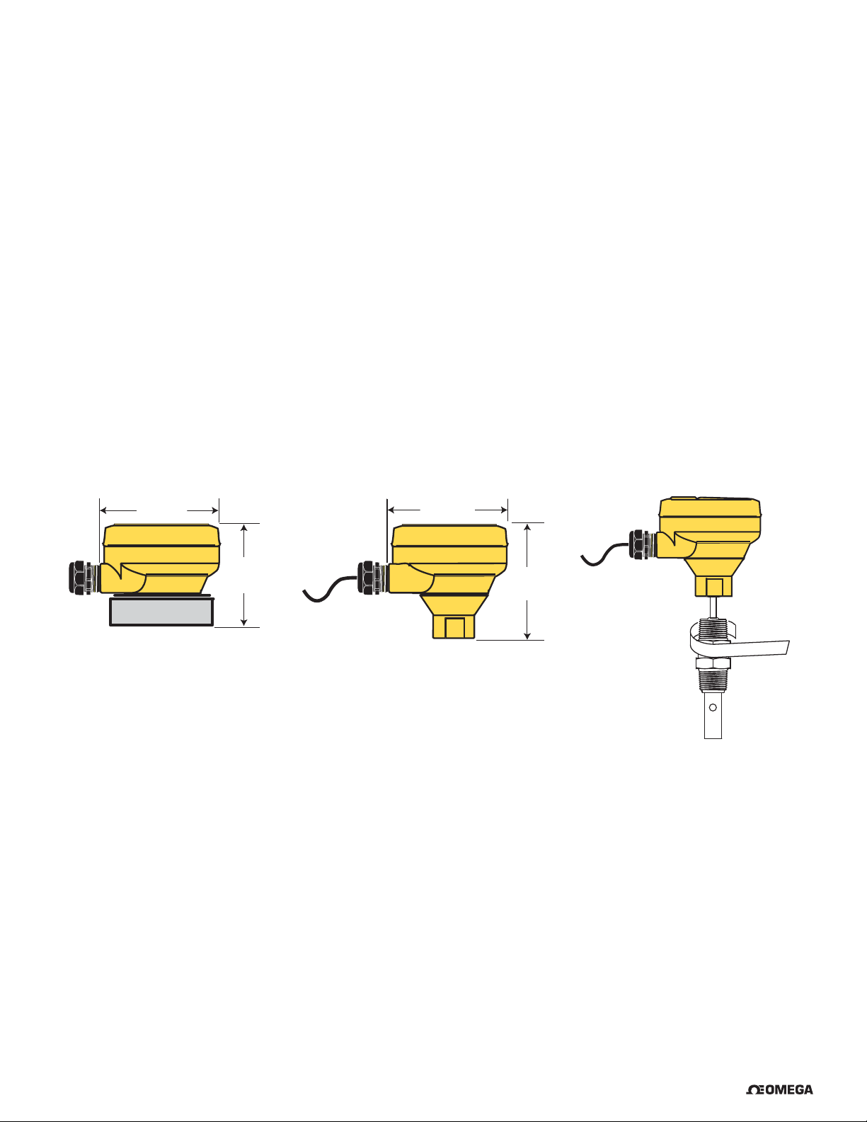
10. Ordering Information
Mfr. Part No. Description
CDTX-2850-IM 2850 Sensor Electronics with 4 to 20 mA Output and ¾ inch adapter
CDTX-2850-RM 2850 Sensor Electronics with 4 to 20 mA and Universal adapter
CDTX-2851 Integral system with CDE-2851, 4 to 20 mA, 0.01 cell, NPT threads
CDTX-2852 Integral system with CDE-2852, 4 to 20 mA, 0.1 cell, NPT threads
CDTX-2853 Integral system with CDE-2853, 4 to 20 mA, 1.0 cell, NPT threads
CDTX-2854 Integral system with CDE-2854, 4 to 20 mA, 10.0 cell, NPT threads
CDTX-2851-ISO Integral system with CDE-2851-ISO, 4 to 20 mA, 0.01 cell, ISO threads
CDTX-2852-ISO Integral system with CDE-2852-ISO, 4 to 20 mA, 0.1 cell, ISO threads
CDTX-2853-ISO Integral system with CDE-2853-ISO, 4 to 20 mA, 1.0 cell, ISO threads
CDTX-2854-ISO Integral system with CDE-2854-ISO, 4 to 20 mA, 10.0 cell, ISO threads
CDTX-285X-RM
Electronics with Universal Adapter
95 mm
(3.74 in.)
82 mm
(3.24 in.)
CDTX-285X-IM
Electronics with ¾-in. Adapter
95 mm
(3.74 in.)
85 mm
(3.34 in.)
CDTX-285X
Integral System
10 CDTX-285X Series Conductivity/Resistivity Sensor Electronics
®
Page 11

WARRANTY/DISCLAIMER
OMEGA ENGINEERING, INC. warrants this unit to be free of defects in materials and workmanship for a
period of 13 months from date of purchase. OMEGA’s WARRANTY adds an additional one (1) month
grace period to the normal one (1) year product warranty to cover handling and shipping time. This
ensures that OMEGA’s customers receive maximum coverage on each product.
If the unit malfunctions, it must be returned to the factory for evaluation. OMEGA’s Customer Service
Department will issue an Authorized Return (AR) number immediately upon phone or written request.
Upon examination by OMEGA, if the unit is found to be defective, it will be repaired or replaced at no
charge. OMEGA’s WARRANTY does not apply to defects resulting from any action of the purchaser,
including but not limited to mishandling, improper interfacing, operation outside of design limits,
improper repair, or unauthorized modification. This WARRANTY is VOID if the unit shows evidence of
having been tampered with or shows evidence of having been damaged as a result of excessive corrosion;
or current, heat, moisture or vibration; improper specification; misapplication; misuse or other operating
conditions outside of OMEGA’s control. Components in which wear is not warranted, include but are not
limited to contact points, fuses, and triacs.
OMEGA is pleased to offer suggestions on the use of its various products. However,
OMEGA neither assumes responsibility for any omissions or errors nor assumes liability for
any damages that result from the use of its products in accordance with information provided
by OMEGA, either verbal or written. OMEGA warrants only that the parts manufactured by the
company will be as specified and free of defects. OMEGA MAKES NO OTHER WARRANTIES OR
REPRESENTATIONS OF ANY KIND WHATSOEVER, EXPRESSED OR IMPLIED, EXCEPT THAT OF
TITLE, AND ALL IMPLIED WARRANTIES INCLUDING ANY WARRANTY OF MERCHANTABILITY
AND FITNESS FOR A PARTICULAR PURPOSE ARE HEREBY DISCLAIMED. LIMITATION OF
LIABILITY: The remedies of purchaser set forth herein are exclusive, and the total liability of
OMEGA with respect to this order, whether based on contract, warranty, negligence,
indemnification, strict liability or otherwise, shall not exceed the purchase price of the
component upon which liability is based. In no event shall OMEGA be liable for
consequential, incidental or special damages.
CONDITIONS: Equipment sold by OMEGA is not intended to be used, nor shall it be used: (1) as a “Basic
Component” under 10 CFR 21 (NRC), used in or with any nuclear installation or activity; or (2) in medical
applications or used on humans. Should any Product(s) be used in or with any nuclear installation or
activity, medical application, used on humans, or misused in any way, OMEGA assumes no responsibility
as set forth in our basic WARRANTY/DISCLAIMER language, and, additionally, purchaser will indemnify
OMEGA and hold OMEGA harmless from any liability or damage whatsoever arising out of the use of the
Product(s) in such a manner.
RETURN REQUESTS/INQUIRIES
Direct all warranty and repair requests/inquiries to the OMEGA Customer Service Department.
BEFORE RETURNING ANY PRODUCT(S) TO OMEGA, PURCHASER MUST OBTAIN AN AUTHORIZED
RETURN (AR) NUMBER FROM OMEGA’S CUSTOMER SERVICE DEPARTMENT (IN ORDER TO AVOID
PROCESSING DELAYS). The assigned AR number should then be marked on the outside of the return
package and on any correspondence.
The purchaser is responsible for shipping charges, freight, insurance and proper packaging to prevent
breakage in transit.
FOR WARRANTY RETURNS, please have the
following information available BEFORE contacting
OMEGA:
1. Purchase Order number under which the product
was PURCHASED,
2. Model and serial number of the product under
warranty, and
3. Repair instructions and/or specific problems
relative to the product.
OMEGA’s policy is to make running changes, not model changes, whenever an improvement is possible. This affords
our customers the latest in technology and engineering.
OMEGA is a registered trademark of OMEGA ENGINEERING, INC.
© Copyright 2016 OMEGA ENGINEERING, INC. All rights reserved. This document may not be copied, photocopied,
reproduced, translated, or reduced to any electronic medium or machine-readable form, in whole or in part, without the
prior written consent of OMEGA ENGINEERING, INC.
FOR NON-WARRANTY REPAIRS,
OMEGA for current repair charges. Have
the following information available BEFORE
contacting OMEGA:
1. Purchase Order number to cover the COST
of the repair,
2. Model and serial number of the product, and
3. Repair instructions and/or specific problems
relative to the product.
consult
Page 12

Where Do I Find Everything I Need for
Process Measurement and Control?
OMEGA…Of Course!
Shop online at omega.com
TEMPERATURE
Thermocouple, RTD & Thermistor Probes, Connectors, Panels & Assemblies
Wire: Thermocouple, RTD & Thermistor
Calibrators & Ice Point References
Recorders, Controllers & Process Monitors
Infrared Pyrometers
PRESSURE, STRAIN AND FORCE
Transducers & Strain Gages
Load Cells & Pressure Gages
Displacement Transducers
Instrumentation & Accessories
FLOW/LEVEL
Rotameters, Gas Mass Flowmeters & Flow Computers
Air Velocity Indicators
Turbine/Paddlewheel Systems
Totalizers & Batch Controllers
SM
pH/CONDUCTIVITY
pH Electrodes, Testers & Accessories
Benchtop/Laboratory Meters
Controllers, Calibrators, Simulators & Pumps
Industrial pH & Conductivity Equipment
DATA ACQUISITION
Communications-Based Acquisition Systems
Data Logging Systems
Wireless Sensors, Transmitters, & Receivers
Signal Conditioners
Data Acquisition Software
HEATERS
Heating Cable
Cartridge & Strip Heaters
Immersion & Band Heaters
Flexible Heaters
Laboratory Heaters
ENVIRONMENTAL
MONITORING AND CONTROL
Metering & Control Instrumentation
Refractometers
Pumps & Tubing
Air, Soil & Water Monitors
Industrial Water & Wastewater Treatment
pH, Conductivity & Dissolved Oxygen Instruments
M5405/0916
 Loading...