

Page 1

User’s Guide
Shop online at
omega.com
e-mail: [email protected]
For latest product manuals:
www.omegamanual.info
MADE IN CHINA
®
CDTX-111
Conductivity Monitor
Page 2

www.omega.com [email protected]
Servicing North America:
U.S.A. Omega Engineering, Inc.
Headquarters: Toll-Free: 1-800-826-6342 (USA & Canada only)
Customer Service: 1-800-622-2378
Engineering Service: 1-800-872-9436
Tel: (203) 359-1660
e-mail: [email protected]
For Other Locations Visit omega.com/worldwide
(USA & Canada only)
(USA & Canada only)
Fax: (203) 359-7700
The information contained in this document is believed to be correct, but OMEGA accepts no liability for any errors it contains, and
reserves the right to alter specifications without notice.
WARNING: These products are not designed for use in, and should not be used for, human applications.
Page 3

C
ONTENTS
. INTRODUCTION …..…………………………………..….…… …….. ......
1
2
2. FEATURES AND TECHNICAL SPECIFICATIONS ……… ………. 2
2.1 Features..…………………………..……………...……… …….… 2
2.2 Technical Specifications……...…………….……… …………....… 2
3. INSTALLATION…….…………………………..………..………............. 3
3.1 Dimension………………...……...…………………..………............. 3
3.2 Panel Cut-out…………….……….……………….....………............ 4
3.3 User Interface and Description……………………………............ 4
3.4 Connection.…………….……..………..…….....……………............ 6
4. SETTING AND OPERATION..……………………..……..……............. 7
4.1 Switch Measuring and Setting Mode……..................……..........7
4.2 Menu Structure……………………..………..….……...……............7
....
.....
4.3 Parameter Setting and Operation.………..….….…...…….......... 9
4.3.1 Set Alarm………...…..………………………..…………............. 9
4.3.2 Calibration………….……..……………..…………..…............. 11
4.3.3
4.3.4 Measurement Mode…….…………..……..……………...........16
4.3.5 Restore Factory Setting.…………………..……………......... 16
5. ERROR CODES…………………...…...……..……..………….............17
6. SENSOR…….……………………………….…..……………….............17
7. STANDARD CONFIGURATION…..…………………..………............20
8. OPTIONAL CONFIGURATION…………..………...…….……............20
Set Current Output………...…..……………..…………..........
14
CDTX-111 Intelligent On-line Conductivity Monitor
1
Page 4

,
1. IN
2. FEA
2.
(1) 3-1/2 LED digital with back-lit display
TRODUCTION
The CDT
instrument. The unit utilizes a multifunction LED to display readings and
provide feedback to the user. The unit includes fully configurable control,
alarm and feedback with up to two relays and 4-20mA current output
sources.
X-111 is a microprocessor controlled conductivity measurement
TURES AND TECHNICAL SPECIFICATIONS
1 Features
(2) Measured conductivity, resistivity, temperature
(3) 0 ~ 100°C automatic/manual temperature compensation
(4) Manual or Automatic buffer adjustment
(5) Restore factory setting function is available
(6) Galvanic separation between inputs and outputs and supply voltage
(7) Different input for excellent noise rejection
(8) High and low programmable alarm, 250V/10A relay output
2.2 Technical Specifications
(1) Ranges of measurement : 0~ 18 MΩ Ω · cm or 0~19.99uS/cm
0~199.
(2) Accuracy:±0.5 % / ±0.2°C
(3) Linearity:±0.1% of range
(4) Repeatability:±0.1% of range
(5) Temperature compensation type:Auto / manual 0°C to 100°C
9uS/cm, 0~1999uS/cm
(6) Alarm Output:Two relays outputs (250V/10A),full range with hysteresis
adjustable
(7) Current output:DC 4~20mA,Opto-isolated outputs,( 750Ω Max. load)
(8) Ambient Operating temperature:-10~+55°C
(9) Humidity:≤95%
2
Page 5
3.
Power supply
(10)
I
NSTALLATION
AC110
~220V
0/60Hz
5
The panel
-mounting version is designed to be flush mounted and sealed in a
square cut-out in a panel, and is held in place with the two screw clamps
provided.
F
igure 1: installation diagram
3.1
D
imensions
F
igure 2 : overall dimensions panel-mounting
CDTX-111
CONDUCTIVITY MONITOR
3
Page 6
3
gu
t
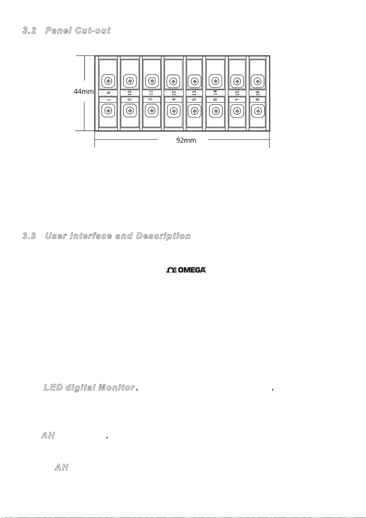
diagram
.2
P
anel Cut-out
i
The panel cut
F
-out for mounting the unit should be 92 mm x 44 mm (+1.0–
e 3: cut-ou
r
0.0).
Two screw clamps are supplied and are fitted from the back of the
instrument
U
3.3
ser Interface and Description
CDTX-111
CONDUCTIVITY MONITOR
igure 4: front panel diagram
ront panel description:
F
(1) L
ED digital Monitor d
F
isplayed the measured values
and
can also be
displayed prompt function, parameter values and error codes in
interactive.
(2) AH alarm light
Under
the conditions of setting high alarm, when the
measured pH value of the solution is higher than the value of High alarm,
the A
H
alarm light will be turned on and the high relay (N/O)
4
close; When
Page 7

th
e measured pH value of the solution is lower than the value of High
alarm, furthermore lower than the hysteresis, the AH alarm light will be
turned off and the high relay (N/O) open.
(3) AL alarm light,Under the conditions of setting low alarm, when the
measured pH value of the solution is lower than the value of low alarm, the
AL alarm light will be turned on and the low relay (N/O) close; When the
measured pH value of the solution is higher than the value of low alarm,
furthermore higher than the hysteresis, the AL alarm light will be turned
off and the low relay (N/O) open.
(4) SET indicator light, the light will be turned on when entering the setting
state.
(5) uS/cm indicator light. Wh en the light is lit in the me asurement state,
means the measured value is conductivity, and unit is uS/cm.
(6) MΩ·cm indicator light. When the light is lit in the measurement sta t e,
means the measured value is resistivity, and unit is MΩ·cm.
(7) indicator light. When the light is lit in the measurement state,means the
measured value is Temperatu r e ; When the light is lit in the setting state,
means the input parameter is Temperature.
(8)
(9) ▲
(10) ▼ ,In
ME
fr
th
di
,
NU
,In
ont menu. To adjust a value, the
e next menu. To adjust a value , the
git.
ess the
Pr
setting state, using the
the setting state, using the
ME
NU
to enter or exit the setting state.
key
▲
key
the user can cycle through the
▲ key
▼
key
▼
key
is used to select a digit.
the user can cycle through
is used to increment the
(11)
EN
th
e setting parameters.
TER
key
is the enter button to confirm enter the menu and store
5
Page 8

3.4 Co
nnection
nnection terminals wiring directions:
Co
(1) AH, High alarm relay(N/O, normally open)
(2) High/Low alarm relay(Common)
(3) AL, Low alarm relay(N/O, normally open)
gure 5: connection terminals diagram
Fi
(4) Spare
(5) Spare
(6) Ground
(7) Power supply terminal: Connect AC110 ~ 220V
(8) Power supply terminal: Connect the power supply phase
(9) Conductivity sensor line A (red)
(10) Conductivity sensor line A (yellow or white)
(11) Spare
(12) Temperature sensor 1 (blue or brown)
(13) Temperature sensor 2 (black)
(14) Spare
(15) 4~20mA current Output (-)
(16) 4~20mA current Output (+)
6
Page 9
7
CAUTION ! :
Set low alarm value
The specified performance of the CDTX-111 is entirely dependent on correct
installation. For this reason, the installer should thoroughly read the
instructions before attempting to make any electrical connections to the unit.
4. SETTING AND OPERATION
After installation, check the connection is correct, then put the sensor into
the test solution, preheat for 10 minutes, you can perform the following
operations.
4
.1 Switch Measuring and Setting Mode
Instrument has two states: measuring state and setting state. After
powering up the device enters the measuring state automatically. In the
measuring state, press MENU to enter the setting state. In the setting state,
press MENU to return to the measuring state.
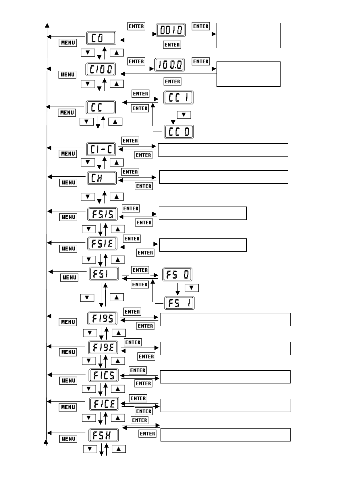
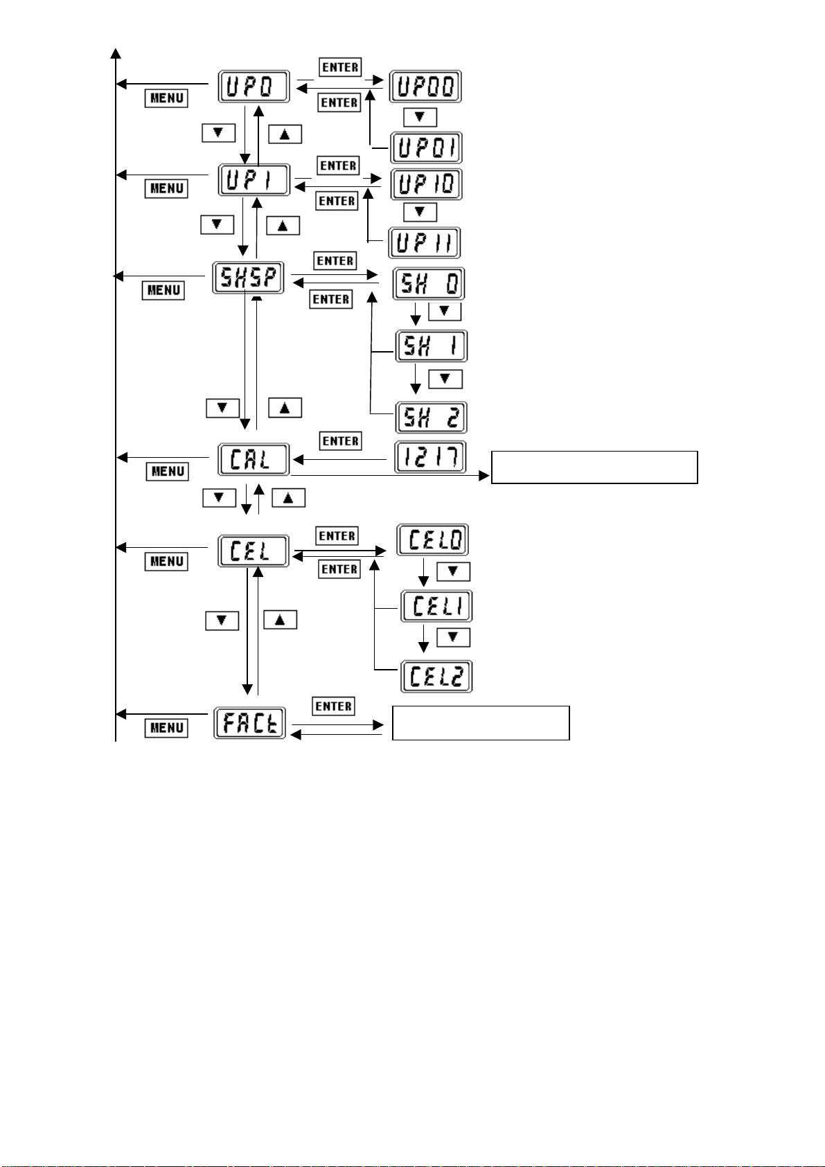
.2 Menu Structure
4
Set high alarm value
Set high alarm
Set low alarm
Page 10
8
(The input for current output is
(Manual Temperature compensation)
Set Temperature compensation
Set Manual temperature compensation
Set current output start
Set current output end
Set conductivity start value for current
Set conductivity end value for current
Set temperature start value for current
Set temperature end value for current
Manual set current output value
Auto calibration
low Temp. value
Auto calibration
high Temp. value
(Auto Temperature
(The input for current output is
Page 11
9
(put the sensor into standard buffer)
Select cell constant k=0.01
(Display temperature
(Manual set low relay
(Manual set low relay open)
(Manual set high relay open)
(Manual set high relay
(Display conductivity value)
(Display resistivity value)
Sensor manual
Select cell constant k=1.00
Select cell constant k=0.10
Restore factory
Auto
4.3 Parameter Setting and Operation
4.3.1 Set Alarm
The CDTX-111 monitor has two alarm outputs designated high alarm (AH)
and low alarm (AL). The alarm value and alarm hysteresis can be set within
the currently selected measuring range.
Page 12
10
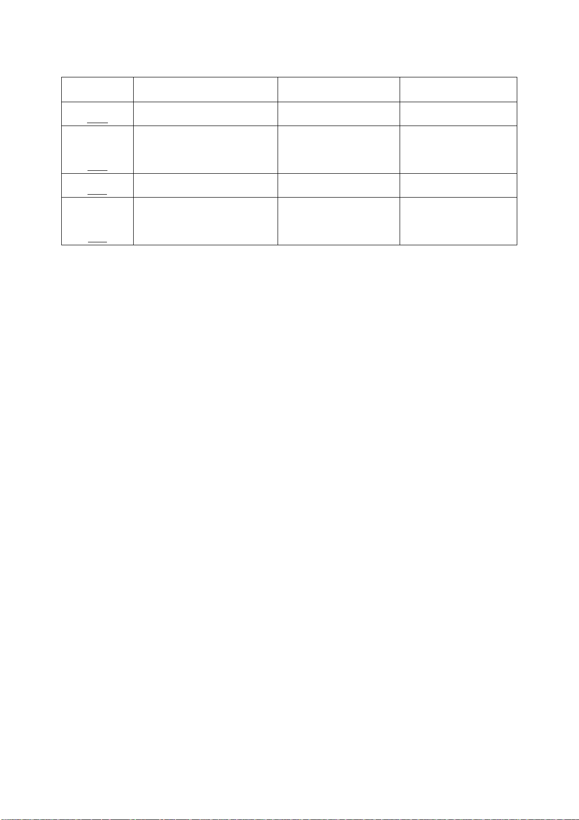
*Note: The setting should meet AH-EH≥AL+EL
Alarm Relay
During normal operation when the alarm is not active, the alarm output will
be in its NORMAL condition, the N/O (normal op en ) contact will be op e n .
When the alarm is active, the alarm output will be in its ALARM condition
and therefore the N/O contact will be closed.
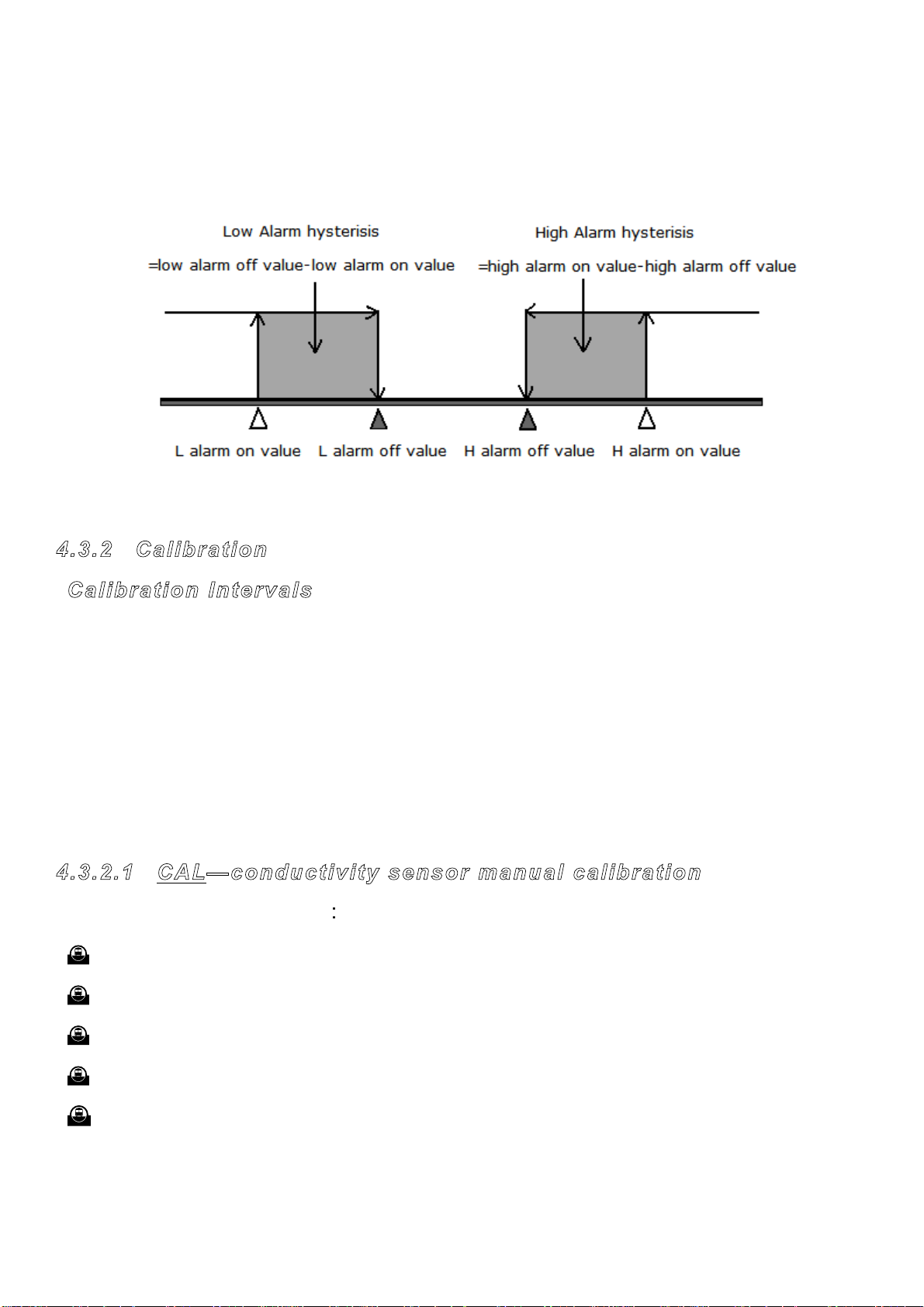
Alarm Hysterisis
In a n o r mal condition an alarm turns on and off at the same value. For
example, if a high alarm turns on at 2000 uS/cm the alarm occurs when the
reading increases to 2000 uS/cm. When it decreases through 2000 uS/cm the
alarm turns off.
Some applications may demand that the alarm turns off at a different value,
for a high alarm this would be value lower than the alarm value, and for a low
alarm this would be a value higher than the alarm value.
The hysterisis value determines the difference between the alarm switch on
point and the alarm switch off point. In the case of a high alarm, hysterisis
Code
Content
Set range
Unit
AH
High alarm value
0~18.00/0~1999
MΩ·cm / uS/cm
EH
High alarm
hysteresis
0~18.00/0~1999
MΩ·cm / uS/cm
AL
Low alarm value
0~18.00/0~1999
MΩ·cm / uS/cm
EL
Low alarm
hysteresis
0~18.00/0~1999
MΩ·cm / uS/cm
Table 1 Alarm value set tin g program
Page 13
11
causes the alarm to turn off at a value that is less than the alarm value. For a
low alarm, hysterisis causes the alarm to turn off at a value greater than the
alarm value.
4.3.2 Calibration
C
alibration Intervals
Figure 6 alarm with
hysterisis
The CDTX-111 Monitor and Sensor combination once calibrated will require
calibration checking/recalibration at 3-6 monthly intervals, however this does
depend on the application. The calibration of the instrument can be effected
by seasonal variations in the measured effluent, however only knowledge of
the application can determine the re-calibration interval required.
4
.3.2.1 CAL—conductivity sensor manual calibration
Preparing For Calibration
Value known conductivity buffer 100ml;
Pure water 300~500ml;
Use pure water to wash the sensor, and then make it dry;
Use thermometer to measure the temperature of buffer;
Select manual temperature compensation in the instrument menu and
input the temperature value of buffer, set the temperature
coefficient is 0.
compensation
Page 14

12
Specific operations: select CAL in the menu and put the dry and clean sensor
into the known conductivity buffer solution, pre ss ENTER to enter its
program, then the instrument displays the measured value of the solution,
and in flashing mode which is different from the measurement states. After
the measurement data is stable then press ENTER again, now only the first
digit flas hing in the display data means it is modify bit. Pr e ss DOWN to
choose the modification bit, press UP key to modify the data, make the
display value as same as the conductivity value of the solution, press
ENTER to store the calibration data(This value is stored even after power
failure), and return to the setting state.
4.3.2.2 C0、C100—temperature calibration
CDTX-111 has temperature measurement function, for the automatic
temperature compensation, and also can be displayed on the monitor.
Temperature calibration requires a high and a low constant temperature
environment. Such as ice water mixture (0℃) and boiling distilled water
(100℃). C0 is used to calibrate 0℃. select C0 in the menu and put the sensor
into 0℃ environment, press ENTER to store the calibration data , and
return to the setting state. The Method of calibrate 100℃ is as same as
calibrate 0℃.
Page 15
13
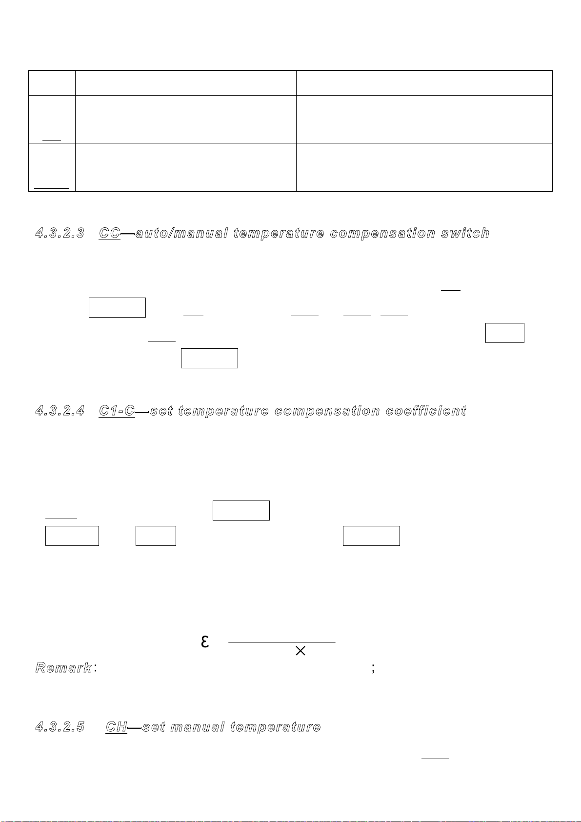
Table 2 Temperature calibration program content
The Calculation Method of coefficient
Code Content Direction
Use Ice water mixture (0°C) to
C0 Auto calibrate temperature=0°C
calibrate
Auto calibrate
C100
temperature=100°C Use boiling water (100°C) to calibrate
4.3.2.3 CC—auto/manual temperature compensation switch
CDTX-111 has Auto and manual temperature compensation function. The
user can select between two modes of compensation by the CC in the menu.
Press ENTER into CC and display CC0 or CC1. CC0 is Auto temperature
compensation, CC1 is manual temperature compensation. Press UP to
switch it, then press ENTER to store and return to the setting state.
4.3.2.4 C1-C—set temperature compensation coefficient
The temperature compensation coefficient is different for each type of
solution, so the temperature compensation coefficient is designed to be
adjustable (25°C as the reference), and the range is 0~±10%. Select
C1-C in the menu, press
ENTER into it and display the original value, use
DOWN and UP to modify it, then press ENTER to store and return to
the setting state. The temperature compensation coefficient works both in
automatic and manual temperature compensation.
Remark cond.25=the conductivity value at t=25°C
cond.35=the conductivity value at t=35°C
cond.35-cond.25
=
Cond.25
100%
.3.2.5 CH—set manual temperature
4
In this mode the instrument should be set with the “CC1” and the user
Page 16

14
Table 3 Temperature compensation program
can set the solution temperature (0~100℃) in the CH menu. Press ENTER
into CH and display the original value, use UP and DOWN to modify it,
then press ENTER to store and return to the setting state.
Code
Content
Direction
CC
Auto/manual temp. compensation
switch
0=Auto/1=manual
C1-C
Temp. compensation coefficient
setting
Range: 0~±10%
CH
Manual temperature setting
Range: 0~100℃
4.3.3 Set Current Output
CDTX-111 has one 4~20mA current output. Th e user can select the input
source: conductivity or temperature. And the current output can be set work
over the whole range of the input source.
The output can be set work over the whole of selected measurement range
(curve1) or a portion of it by setting of the output start and end values
(curve2). It is also possible to configure the output to work reverse to normal,
i.e. a 4 – 20 mA output where 20 mA corresponds to the zero display value
and 4 mA corresponding to the full scale value. (curve3).
Figure 7 Current span curve
Page 17
15
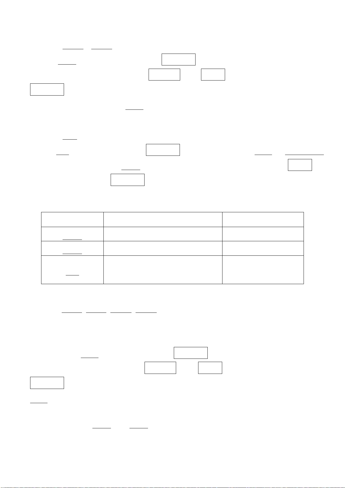
Table 6 Set current output
4.3.3.1 FSIS、FSIE—set current output start and end value
Select FSIS in the menu, press ENTER into it and display the original
current output start value, use DOWN and UP to modify it, then press
ENTER to store and return to the setting state.
The same method select FSIE to set the current output end value.
4.3.3.2 FSI—select the input for the current output
Select FSI in the menu, press ENTER int o it and display FS 0 or FS 1. FS 0
is conductivity iutput, FS 1 is te m p era ture as the input. Press UP to
switch it, then Press ENTER to store and return to the setting state.
Code
Content
Direction
FSIS
Current output start value
4.00~20.00 mA
FSIE
Current output end value
4.00~20.00 mA
FSI
The input for the current
output
0: conductivity
1: temperature
4.3.3.3 FIgS、FIgE、FICS、FICE—set input value range for the current
output
After selecting the input parameters, you can set its start value and end
value. Select FIgS in the menu, press ENTER into it and display the original
conductivity start value, use DOWN and UP to modify it, then press
ENTER to store and return to the setting state. The same method select
FIgE to set the conductivity end value.
Likewise, select FICS and FICE to set the temperature start and end value for
current output.
Page 18
16
SH 2
Display Temperature
C/F lights
K=0.01/0.1/1.0
Table 8
Measurement Mode
Table 7
Set input range for the current output
Code Content Range
FIgS
FIgE
FICS Temperature start value
FICE Temperature end value 0~100
Conductivity start value
Conductivity end value
0~1999uS/cm (k=1.0)
0~1999uS/cm (k=1.0)
0~100
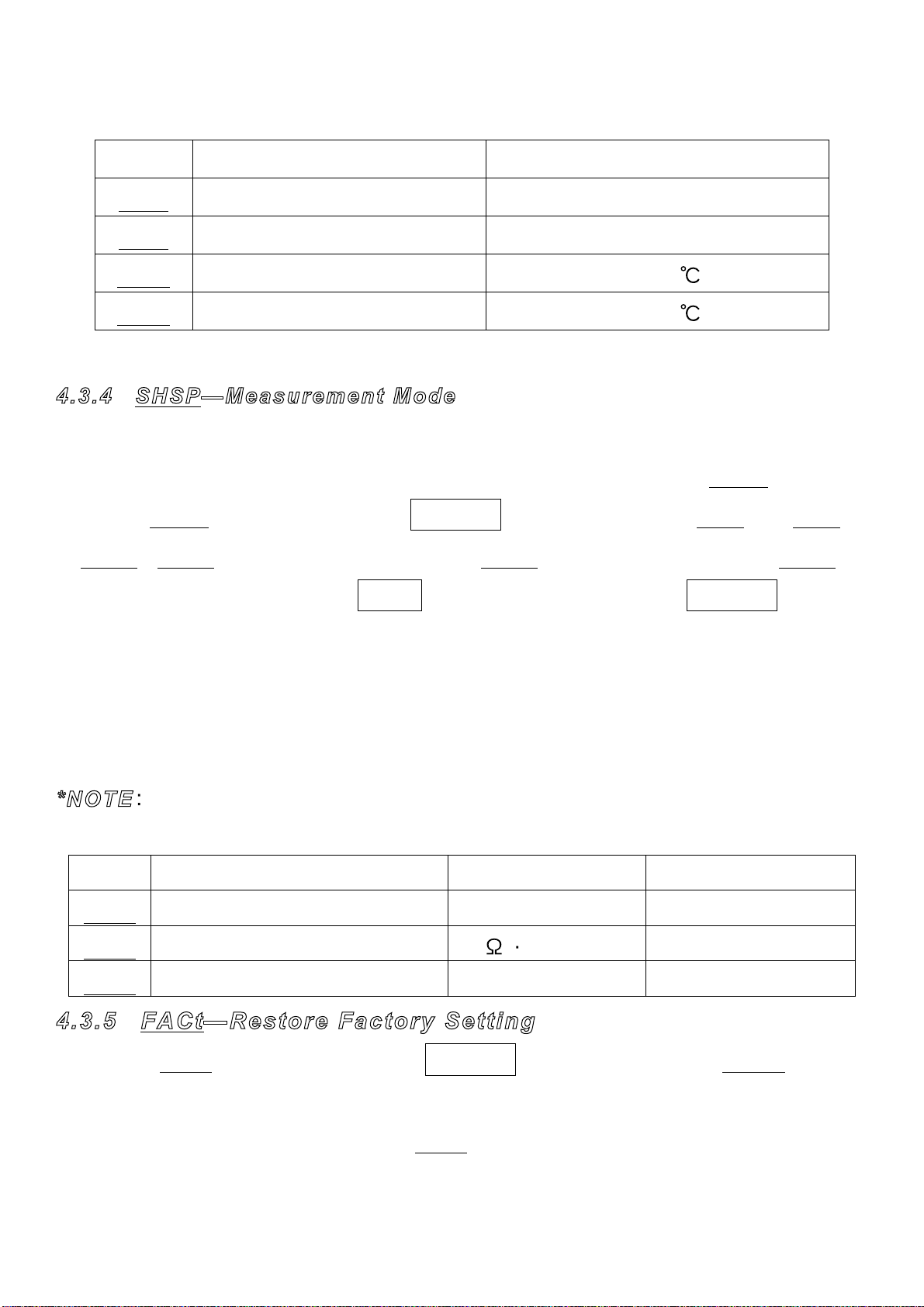
4.3.4 SHSP—Measurement Mode
CDTX-111 has conductivity, resistivity, TDS and temperature four modes of
measurement and display functions, it can be selected in the SHSP program.
Select SHSP in the menu, press ENTER into it and display SH 0 or SH 1 or
SH 2. SH 0 is conductivity mode, SH 1 is resistivity mode, SH 2 is
temperature mode. Press UP to switch it, then Press ENTER to store
and return to the setting state. The indicator light also changes to indicate
that the display state changes. The corresponding parameters in the setting
also will automatically change.
*
NOTE The sensor should be changed when switch the measurement mode.
Code Content Indicator light
SH 0
SH 1
Display conductivity
Display resistivity value
uS(mS)/cm
M cm lights K=0.01
4.3.5 FACt—Restore Factory Setting
Select FACt in the menu, press ENTER into it and display HHHH. At this
moment the instrument is being restored factory setting, about 10 seconds
Cell constant
K=0.01/0.1/1.0
it will automatically returns to FACt, restore factory setting is completed.
After this process, all value the user set before becomes the factory
Page 19

17
calibration value. This function is generally used for replace with new
sensor or data confusion. Generally after restored factory setting, it need
recalibration before using.
5. ERROR CODES
When the instrument detects an error condition, an error code will be
displayed. All the error codes are described below.
6. SENSOR
We use foreign advance technology to manufacture our conductivity sensor.
The quality of the sensor is excellence and it can be used in industry
province with all kind of conductivity monitor.
6.1 Sensor Features
High sensitivity and accuracy with reliability and durability
Stainless material
Quickly response (within two seconds) and stability
Unique structure preventing the sensor from pollution and blockage
Easy to assemble and clean
Code
Content
Solve methods
Er02
Measurement
value out of range
Check whether the choice of cell constant
is suitable and replace the correct one
Er03
Temperature
sensor failure
1. Check whether the temperature sensor
connected with the monitor properly
2. Check whether the temp. compensation
(menu CC) setting correct
Table 9 Error codes
Page 20
18
6.2 Sensor Parameters
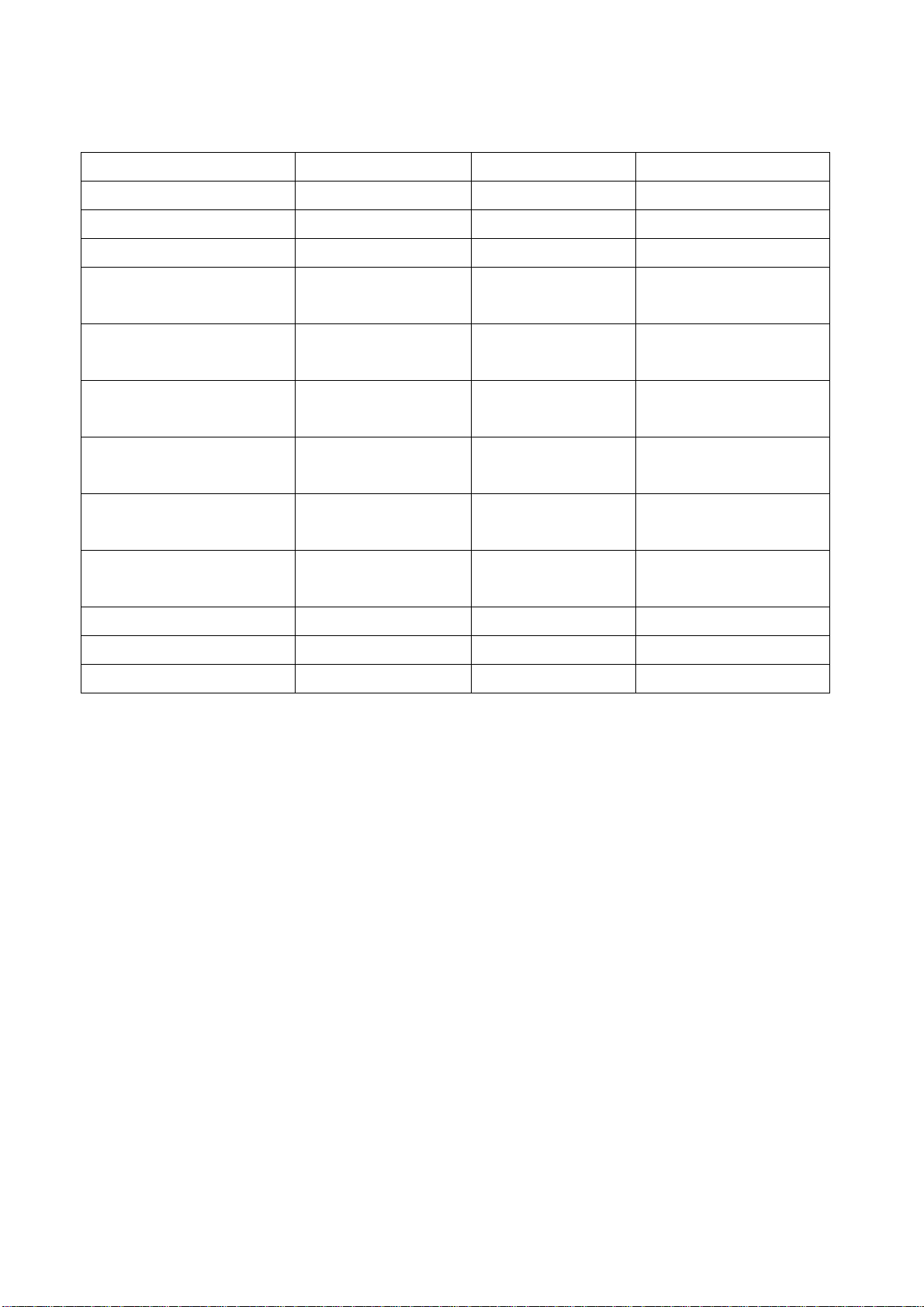
Table 10 Sensor parameters
6.3 The Use Situation of Conductivity Sensor
CDE-100-001
CDE-100-01
CDE-100-1
Parameter
Resistivity
Conductivity
Conductivity
Medium
Pure Water
Water
Water
cell constant
0.01
0.1
1.0
Range
0~18MΩ or
0~19.99us/cm
0~199.9us/c
m
0~1999 us/cm
Temp. range
0~60℃
0~60℃
0~60℃
Temperature
Measurement
0~60℃
0~60℃
0~60℃
Compensation
Resistor
10K
10K
10K
Quantity of
threads
1 1 1
Thread Size
1/2″NPT
1/2″NPT
1/2″NPT
Max pressure
0.6MPa
0.6MPa
0.6MPa
Cables Length
5m
5m
5m
Max Length
50m
20m
20m
Page 21
19
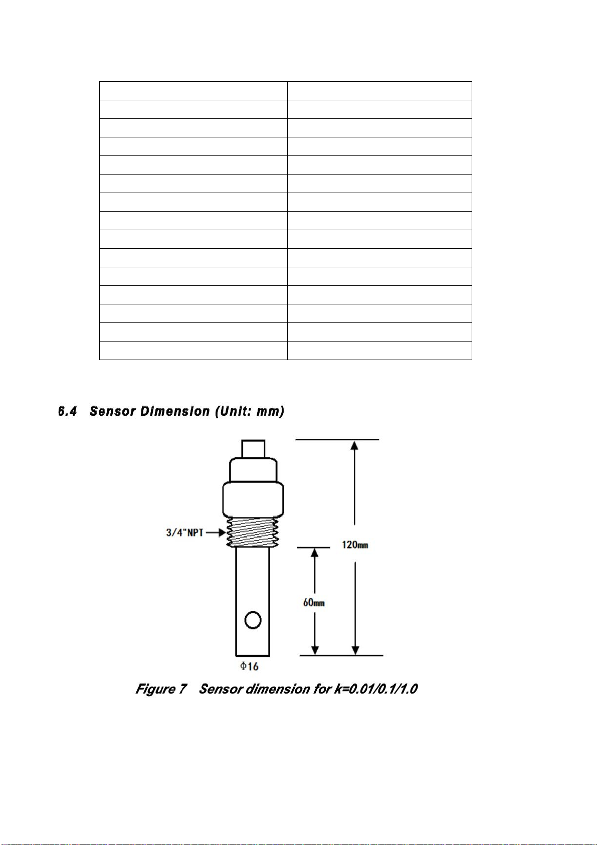
Table 11 The conductivity of different liquid in 25℃
6.4 Sensor Dimension (Unit: mm)
Figure 7 Sensor dimension for k=0.01/0.1/1.0
situation
conductivity
Pure water
0.05 us/cm
Boiler water
0.05~1 us/cm
Deionized water
0.5 us/cm
Distilled water
0.1~10 us/cm
Softened water
1~80 us/cm
Mineral water
10 us/cm
Beverages
0. 5~1 ms/cm
Waste water
0. 9~9 ms/cm
KCL Solution
1.4ms/cm
Brine
1~80ms/cm
Industrial process water
7~140ms/cm
Seawater
53 ms/cm
10%NaOH
355 ms/cm
31%HNO3
865 ms/cm
Page 22

20
6.5 Maintenance
(1) Attaching sensors are precision devices, can not disassemble in order
to avoid changing the cell constant, causing measurement errors.
(2) Sensors can not be immersed in the strong acid or alkali to avoid
surface damage of the sensors, affecting the cell constant and
sensitivity.
Correct method: When the sensor is dirty, immerse in the 10%
hydrochloric acid for a short time, then rinse with pure water that
maintain the sensor surface clean.
(3) Sensors cable is a dedicated cable, can not be replaced or extended by
users self.
(4) Instrument should be installed in a relatively dry environment or the
control box, to avoid instrument failure or measurement error caused
by damp.
7 STANDARD CONFIGURATION
CDTX-111 monitor
Mounting fixing of monitor
Operation guide
Inspection report
8 OPTIONAL CONFIGURATION
Conductivity sensor CDE-100-01/CDE-100-1 (cable length 5 meters)
Resistivity sensor CDE-100-001 (cable length 5 meters)
Extension cable
Page 23

WARRANTY/DISCLAIMER
OMEGA ENGINEERING, INC. warrants this unit to be free of defects in materials and workmanship for a
period of 13 months from date of purchase. OMEGA’s WARRANTY adds an additional one (1) month
grace period to the normal one (1) year product warranty to cover handling and shipping time. This
ensures that OMEGA’s customers receive maximum coverage on each product.
If the unit malfunctions, it must be returned to the factory for evaluation. OMEGA’s Customer Service
Department will issue an Authorized Return (AR) number immediately upon phone or written request.
Upon examination by OMEGA, if the unit is found to be defective, it will be repaired or replaced at no
charge. OMEGA’s WARRANTY does not apply to defects resulting from any action of the purchaser,
including but not limited to mishandling, improper interfacing, operation outside of design limits,
improper repair, or unauthorized modification. This WARRANTY is VOID if the unit shows evidence of
having been tampered with or shows evidence of having been damaged as a result of excessive corrosion;
or current, heat, moisture or vibration; improper specification; misapplication; misuse or other operating
conditions outside of OMEGA’s control. Components in which wear is not warranted, include but are not
limited to contact points, fuses, and triacs.
OMEGA is pleased to offer suggestions on the use of its various products. However,
OMEGA neither assumes responsibility for any omissions or errors nor assumes liability for
any damages that result from the use of its products in accordance with information provided
by OMEGA, either verbal or written. OMEGA warrants only that the parts manufactured
by it will be as specified and free of defects. OMEGA MAKES NO OTHER WARRANTIES OR
REPRESENTATIONS OF ANY KIND WHATSOEVER, EXPRESS OR IMPLIED, EXCEPT
THAT OF TITLE, AND ALL IMPLIED WARRANTIES INCLUDING ANY WARRANTY OF
MERCHANTABILITY AND FITNESS FOR A PARTICULAR PURPOSE ARE HEREBY
DISCLAIMED. LIMITATION OF LIABILITY: The remedies of purchaser set forth herein are
exclusive, and the total liability of OMEGA with respect to this order, whether
based on contract, warranty, negligence, indemnification, strict liability or otherwise,
shall not exceed the purchase price of the component upon which liability
is based. In no event shall OMEGA be liable for consequential, incidental or special damages.
CONDITIONS: Equipment sold by OMEGA is not intended to be used, nor shall it be used: (1) as a “Basic
Component” under 10 CFR 21 (NRC), used in or with any nuclear installation or activity; or (2) in medical
applications or used on humans. Should any Product(s) be used in or with any nuclear installation or
activity, medical application, used on humans, or misused in any way, OMEGA assumes no responsibility
as set forth in our basic WARRANTY / DISCLAIMER language, and, additionally, purchaser will indemnify
OMEGA and hold OMEGA harmless from any liability or damage whatsoever arising out of the use of the
Product(s) in such a manner.
RETURN REQUESTS/INQUIRIES
Direct all warranty and repair requests/inquiries to the OMEGA Customer Service Department.
BEFORE RETURNING ANY PRODUCT(S) TO OMEGA, PURCHASER MUST OBTAIN AN AUTHORIZED
RETURN (AR) NUMBER FROM OMEGA’S CUSTOMER SERVICE DEPARTMENT (IN ORDER TO AVOID
PROCESSING DELAYS). The assigned AR number should then be marked on the outside of the return
package and on any correspondence.
The purchaser is responsible for shipping charges, freight, insurance and proper packaging to prevent
breakage in transit.
FOR WARRANTY RETURNS, please have the
following information available BEFORE
contacting OMEGA:
1. Purchase Order number under which the product
was PURCHASED,
2. Model and serial number of the product under
warranty, and
3. Repair instructions and/or specific problems
relative to the product.
OMEGA’s policy is to make running changes, not model changes, whenever an improvement is possible. This affords
our customers the latest in technology and engineering.
OMEGA is a registered trademark of OMEGA ENGINEERING, INC.
© Copyright 2016 OMEGA ENGINEERING, INC. All rights reserved. This document may not be copied, photocopied,
reproduced, translated, or reduced to any electronic medium or machine-readable form, in whole or in part, without the
prior written consent of OMEGA ENGINEERING, INC.
FOR NON-WARRANTY REPAIRS,
for current repair charges. Have the following
information available BEFORE contacting OMEGA:
1. Purchase Order number to cover the COST
of the repair,
2. Model and serial number of the product, and
3. Repair instructions and/or specific problems
relative to the product.
consult OMEGA
Page 24

Where Do I Find Everything I Need for
Process Measurement and Control?
OMEGA…Of Course!
Shop online at omega.com
TEMPERATURE
MU
Thermocouple, RTD & Thermistor Probes, Connectors, Panels & Assemblies
MU
Wire: Thermocouple, RTD & Thermistor
MU
Calibrators & Ice Point References
MU
Recorders, Controllers & Process Monitors
MU
Infrared Pyrometers
PRESSURE, STRAIN AND FORCE
MU
Transducers & Strain Gages
MU
Load Cells & Pressure Gages
MU
Displacement Transducers
MU
Instrumentation & Accessories
FLOW/LEVEL
MU
Rotameters, Gas Mass Flowmeters & Flow Computers
MU
Air Velocity Indicators
MU
Turbine/Paddlewheel Systems
MU
Totalizers & Batch Controllers
sm
pH/CONDUCTIVITY
MU
pH Electrodes, Testers & Accessories
MU
Benchtop/Laboratory Meters
MU
Controllers, Calibrators, Simulators & Pumps
MU
Industrial pH & Conductivity Equipment
DATA ACQUISITION
MU
Data Acquisition & Engineering Software
MU
Communications-Based Acquisition Systems
MU
Plug-in Cards for Apple, IBM & Compatibles
MU
Data Logging Systems
MU
Recorders, Printers & Plotters
HEATERS
MU
Heating Cable
MU
Cartridge & Strip Heaters
MU
Immersion & Band Heaters
MU
Flexible Heaters
MU
Laboratory Heaters
ENVIRONMENTAL
MONITORING AND CONTROL
MU
Metering & Control Instrumentation
MU
Refractometers
MU
Pumps & Tubing
MU
Air, Soil & Water Monitors
MU
Industrial Water & Wastewater Treatment
MU
pH, Conductivity & Dissolved Oxygen Instruments
M5430/1016
 Loading...