

Page 1
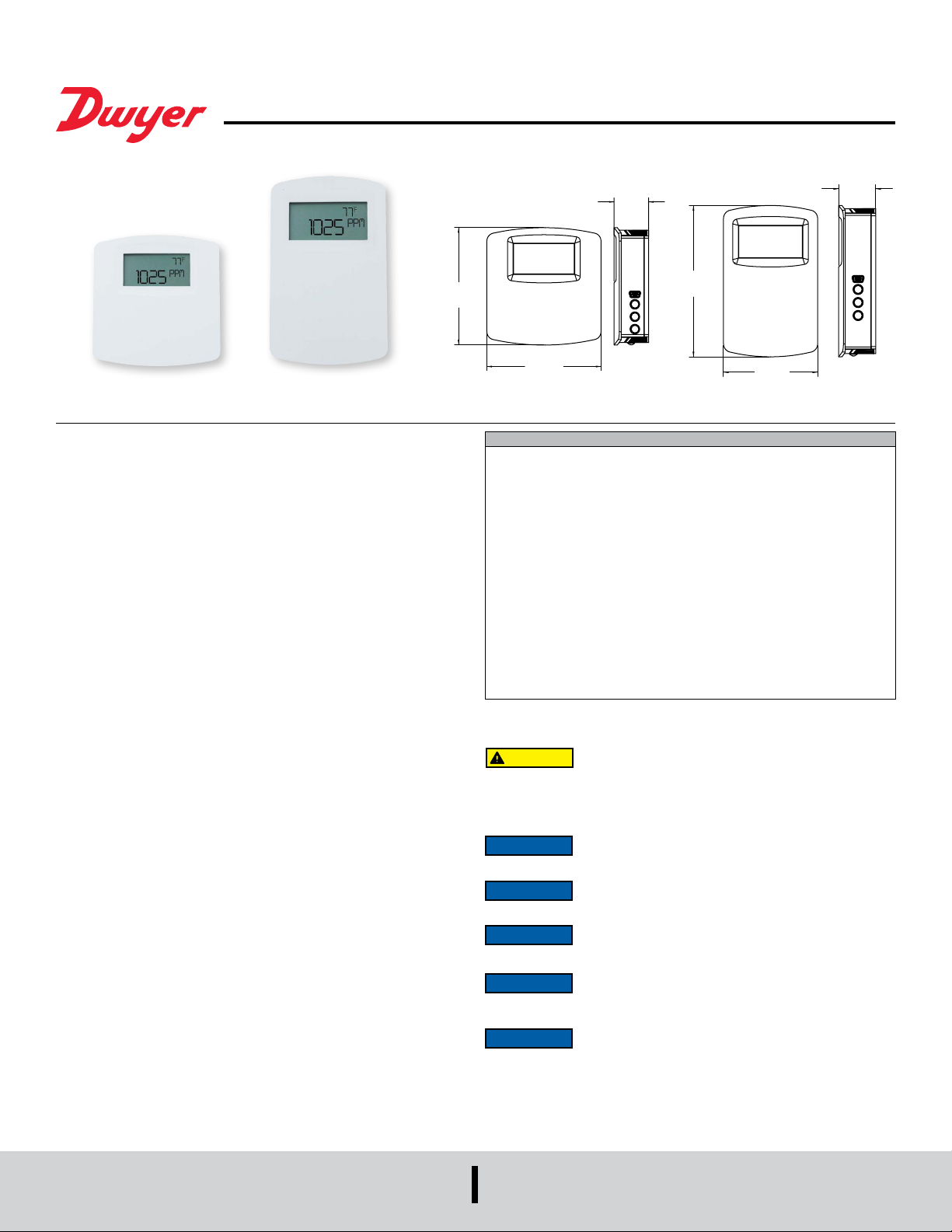
Bulletin AQ-CDT/CDTR-E/N-2
[92.72]
[71.12]
1.10
®
Series CDT and CDTR Wall Mount Carbon Dioxide/
Temperature Transmitter
Specications - Installation and Operating Instructions
3.65
North AmericanEuropean
Series CDT and CDTR Wall Mount Carbon Dioxide Temperature Transmitters
accurately monitor the CO2 concentration and temperature in schools, ofce buildings,
and other indoor environments to help achieve LEED® certication. Additionally, the
Series CDTR also measures ambient relative humidity. For increased sensor life,
a single- beam dual-wavelength non-dispersive infrared (NDIR) sensor is used to
automatically correct the measurement in both occupied and unoccupied buildings
against aging effects. The single-beam dual-wavelength sensor technology provides
the highest level of accuracy compared to Automatic Baseline Correction methods,
which can unintentionally shift the calibration based on CO2 levels and barometric
pressure conditions. In order to achieve a higher level of accuracy, the Series CDT
includes digital barometric pressure adjustment and the ability to eld-calibrate the
sensor.
Universal outputs allow users to select the transmitter output to be 4-20 mA, 0-5 VDC,
or 0-10 VDC to work with virtually any building management controller. An optional
relay with user adjustable set points can be used to control exhaust fans, open
actuated windows or dampers, or signal a light or horn.
For applications that require visual indication, the Series CDT and CDTR can be
ordered with an integral LCD display, Model A-449 or Model A-449A remote LCD
display that can plug into the mini-connector port on the side of the transmitter. Both
the CDT and CDTR can be congured to display temperature only, CO2 only, or CO2
and temperature together. The Series CDTR can also display relative humidity or
CO2 and relative humidity together. Push buttons are standard on the transmitters for
access to the menu structure, but the transmitter can be ordered without the buttons.
To prevent tampering, the action of the buttons can be locked out using an internal dip
switch selection. Menu items that can be accessed include: engineering units, relay
output set points, display conguration, transmitter output scaling, ambient barometric
pressure and eld calibration of the transmitter.
Single-beam dual-wavelength sensor advantages:
• Automatically corrects for aging effects in occupied and unoccupied buildings*
◦ Perfect for hospitals and manufacturing plants that are occupied 24 hours per
day
• Measures actual unltered light intensity directly
◦ Eliminates error from incorrect assumptions of gas concentration in theoretical
logic assumption methods
*For buildings occupied 24 hours per day, it is recommended that calibration be
veried every 6 to 12 months depending on application.
1.08
[27.33]
4.50
[114.30]
3.56
[90.42]
SPECIFICATIONS
Sensor: Single beam, dual-wavelength NDIR.
Range: CO2: 0 to 2000 or 0 to 5000 PPM (depending on model); Temperature: 32
to 122°F (0 to 50°C).
Accuracy: CO2: ±40 PPM ±3% of reading; RH: ±2% (10 to 90% RH) (for units
congured with humidity output); Temperature: ±1°C @ 25°C.
Temperature Dependence: ±8 PPM/°C at 1100 PPM.
Non-Linearity: 16 PPM.
Pressure Dependence: 0.13% of reading per mm of Hg.
Response Time: 2 min for 99% step change.
Temperature Limits: 32 to 122°F (0 to 50°C).
Humidity Limits: 10 to 95% RH (non-condensing).
Power Requirements: 16-35 VDC or 19-28 VAC.
Power Consumption: Average: 2 w; Peak: 3.75 w.
Output: Current: 4-20 mA (max. 500 Ω); Voltage: 0-5 VDC or 0-10 VDC (min. 500
Ω); Relay: SPST NO rated 2A @ 30 VDC; RTD or thermistor per r-t curves on page
4 (depending on model).
Weight: 4.4 oz (125 g).
Agency Approvals: CE.
INSTALLATION
CAUTION
Make sure all connections are in accordance with the job wiring diagram and in
accordance with national and local electrical codes. Use copper conductors only.
NOTICE
NOTICE
NOTICE
NOTICE
transmitter to adjust to the current CO2 concentration.
NOTICE
days.
Disconnect power supply before installation to prevent electrical
shock and equipment damage.
Use electrostatic discharge precautions (e.g., use of wrist straps)
during installation and wiring to prevent equipment damage.
Avoid locations where severe shock or vibration, excessive
moisture or corrosive fumes are present.
Do not exceed ratings of this device, permanent damage not
covered by warranty may result.
Upon powering the transmitter, the rmware version will ash on
the display. A warm up period of 30 minutes is required for the
Self calibration feature of the transmitter requires exposure to
normal outdoor equivalent carbon dioxide level once every thirty
2.80
[27.96]
DWYER INSTRUMENTS, INC.
P.O. BOX 373 • MICHIGAN CITY, INDIANA 46360, U.S.A.
Phone: 219/879-8000
Fax: 219/872-9057
www.dwyer-inst.com
e-mail: [email protected]
Page 2
Current / Voltage Outputs
TURE
POWER
TEMP OR RH
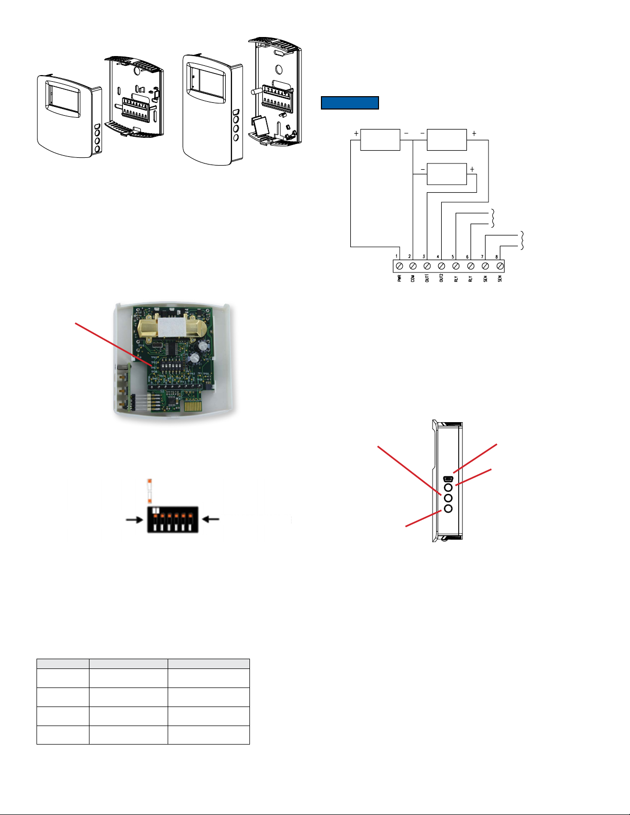
On the Series CDT, the transmitter may be wired for current or voltage output for both
carbon dioxide and temperature. On the Series CDTR, the transmitter may be wired
for current or voltage output for both carbon dioxide and humidity. The transmitter can
be powered with either 16-35 VDC or 19-28 VAC. Wire the transmitter according to
Figure 4.
NOTICE
Optional relay can be used as either a dry contact or low voltage
switched circuit up to 2 A at 30 VDC
Figure 1: Removal of cover from back plate
MOUNTING
1. Push tab on top and bottom of cover and lift cover from back plate (see Figure 1).
2. Select the mounting location, away from diffusers, lights or any external
inuences.
3. Mount transmitter on a vertical surface to a standard electrical box using the two
#6 M2C type screws provided.
4. Pull wires through sub base hole and make necessary connections.
5. Reattach cover to base plate.
WIRING
Use maximum 18 AWG wire for wiring to terminals. Refer to Figure 4 for wiring
information.
Dip Switch
Figure 2: Diagram of circuit board
DIP SWITCH SETTINGS
To access the DIP SWITCH, remove the cover of the unit as shown in Figure 2. The
DIP SWITCH is located on the back of the circuit board.
SUPPLY
Figure 4: Active output wiring diagram
Remote Display
For models that are ordered without an integral LCD display, remote display Model
A-449 can be used to display the temperature, humidity, and carbon dioxide. The mini
USB plug of the remote display plugs into the receptor on the side of the housing.
After a short warm up time, the display will begin to show the current temperature and
carbon dioxide measurements unless congured by the user to show humidity and
carbon dioxide, only temperature, only humidity, or only carbon dioxide.
EDITING MENU PARAMETERS
Before any adjustment can be made to the transmitter, the Menu Lockout Dip Switch
must be set to the ˝On˝ position (See Figure 3)
Enter
RECEIVER
CO2
RECEIVER
RELAY
CONTACT
PASSIVE
TEMPERA
SENSOR
Remote display port
Up
UP = “ON”
DOWN = “OFF”
DIP SWITCH #1
DIP SWITCH
Figure 3
DIP Switch Position 1: CO2 Output Selection
ON: Output set to voltage output
OFF: Output set to current output
DIP Switch Position 2: Temperature (CDT models) / Humidity (CDTR models)
Output Selection
ON: Output set to voltage output
OFF: Output set to current output
DIP Switch Positions 3 & 4: Current or Voltage Output Range Selection
Output Range DIP Switch 3 Position DIP Switch 4 Position
2-10 V
4-20 mA
0-10 V
0-20 mA
0-5 V
0-10 mA
1-5 V
2-10 mA
Dip Switch Position 5: Menu Access
ON: Menu Enabled
OFF: Menu Disabled
ON OFF
OFF OFF
OFF ON
ON ON
DIP SWITCH #6
Down
Figure 5: Side view of transmitter
ACCESSING MENU PARAMETERS
Step 1: To enter the menu structure, press Up button and Down button
simultaneously for 5 seconds (display will show RON parameter).
Step 2: Press Up button or Down button to cycle between menu items.
Step 3: Press Enter to edit the value for the displayed menu item (SET will appear
on display).
Step 4: Press Up button or Down button to adjust the value of the menu item.
Step 5: Press Enter button to save the changes (SET will disappear).
Step 6: Repeat Steps 2 through 5 for each of the parameters.
Step 7: To exit the menu at any time, press and hold Up button and Down button
simultaneously for 5 seconds or wait 10 seconds without pushing any
buttons.
Page 3

Menu Descriptions
Relay on set point
RON
Sets the CO2 concentration which the optional relay is energized.
Low limit: 0 PPM
Factory setting: 1000 PPM
High limit: 2000/5000 PPM (depending on model)
Relay off set point
ROF
Sets the CO2 concentration which the optional relay is de-energized. Setting
value lower than RON provides direct action for detecting high concentrations
of CO2. Setting value higher than RON provides indirect action for detecting
low concentrations of CO2. Up button and Down button on the LCD display
will be lit to indicate when the relay is energized.
TOH
Temperature high output range (Series CDT with active temperature only)
Sets the temperature for the highest output (20 mA, 5 VDC or 10 VDC).
When TOH is set above TOL, the transmitter is direct acting and the output
will increase with an increase in temperature. When TOH is below TOL, the
transmitter is reverse acting and the output will increase with a decrease in
temperature.
Low limit: 32.0°F / 0.0°C
Factory setting: 122.0°F / 50.0°C
High limit: 122.0°F / 50.0°C
HOL
Humidity low output range (Series CDTR only)
Sets the humidity for the lowest output (4 mA or 0 VDC).
Low limit: 0 PPM
Factory setting: 950 PPM
High limit: 2000/5000 PPM (depending on model)
Display conguration
DSP
Determines the LCD display conguration during normal operation. The LCD
display can indicate the CO2 concentration, temperature, relative humidity
(Series CDTR only) and CO2 concentration combined with temperature or
relative humidity (Series CDTR only).
CH CO2 concentration and relative humidity (Series CDTR only)
CT CO2 concentration and temperature
TH Temperature and relative humidity (Series CDTR only)
C CO2 concentration only
T Temperature only
H Relative humidity only (Series CDTR only)
Units selection
UNI
Temperature and barometric pressure measurements can be displayed in US
engineering units or SI engineering units. The factory default is to display US
engineering units.
US units °F for temperature and in Hg for barometric pressure
SI units °C for temperature and hPa for barometric pressure
CO2 low output range
COL
Sets the CO2 concentration for the lowest output (4 mA or 0 VDC).
Low limit: 0 PPM
Factory setting: 0 PPM
High limit: 2000/5000 PPM (depending on model)
CO2 high output range
COH
Sets the CO2 concentration for the highest output (20 mA, 5 VDC or 10 VDC).
When COH is set above COL, the transmitter is direct acting and the output
will increase with an increase in CO2 level. When COH is below COL, the
transmitter is reverse acting and the output will increase with a decrease in
CO2 level.
Low limit: 0 PPM
Factory setting: 2000/5000 PPM (depending on model)
High limit: 2000/5000 PPM (depending on model)
Average Atmospheric Carbon Dioxide value
AAC
Sets the value at which the sensors automatic background calibration will
reference. Factory setting derived from research from the National Oceanic
and Atmospheric Administration (NOAA).
Low Limit: 200 PPM
Factory Setting: Current NOAA value
High Limit: 9999 PPM
Temperature low output range (Series CDT with active temperature only)
TOL
Sets the temperature for the lowest output (4 mA or 0 VDC).
Low limit: 32.0°F / 0.0°C
Factory setting: 32.0°F / 0.0°C
High limit: 122.0°F / 50.0°C
Low limit: 0.0%
Factory setting: 0.0%
High limit: 100.0%
HOH
Humidity high output range (Series CDTR only)
Sets the humidity for the highest output (20 mA, 5 VDC or 10 VDC).
When HOH is set above HOL, the transmitter is direct acting and the output will
increase with an increase in humidity. When HOH is below HOL, the transmitter
is reverse acting and the output will increase with a decrease in humidity.
Low limit: 0.0%
Factory setting: 100.0%
High limit: 100.0%
BAR
Barometric pressure
Sets the typical barometric pressure for the location where the transmitter is
mounted. The factory setting is for standard pressure at sea level. Adjusting the
barometric pressure gives a more accurate measurement, especially at higher
elevations. Refer to the elevation charts in Figure 7 for typical barometric
pressures at a given elevation.
Low limit: 20.0 in Hg / 677 hPa
Factory setting: 29.9 in Hg / 1013 hPa
High limit: 32.0 in Hg / 1084 hPa
CAL
Calibration
Calibrates the carbon dioxide sensor to a known gas value. Read
calibration instructions before using this feature. Hold Enter button for 5
seconds.
RST
Reset to Factory Defaults
Resets all menu settings to their default value, and clears zero and span.
YES - Press & hold -- button for several seconds to reset settings
NO - Press -- button to exit this menu item without resetting
CALIBRATING SENSOR
Step 1: Remove the cover as shown in Figure 1.
Step 2: Remove one of the gas nipple covers on the CO2 sensor and attach tubing
from the gas pressure regulator to the nipple (See Figure 6).
Step 3: Attach the terminal block accessory to the circuit board so that the power wires
line up with terminals 1 and 2. Plug in the power supply to power up the
transmitter.
Step 4: Hold housing so that the sensor is in the vertical plane as shown in Figure 6.
Step 5: Flow zero reference gas at 0.3 SLPM for 5 minutes.
Step 6: Press and hold the Up and Down buttons simultaneously for 5 seconds to
enter the menu parameters. The display will show the “RON” parameter.
Step 7: Press the Up or Down button to access the calibration parameter menu which
will display as “CAL”.
Step 8: Press the Enter button. “SET” will then appear on the display.
Step 9: Press the Down arrow for 3 seconds. All dashes will appear on the display,
then release the button. Then after 10 seconds “SET” will disappear.
Step 10: Exit the parameter menu by pressing and holding the Up and Down buttons
simultaneously for 5 seconds or wait 10 seconds.
Step 11: Flow the full scale reference gas at 0.3 SLPM for 5 minutes.
Step 12: Repeat steps 6 through 8.
Step 13: Press the Up arrow for 3 seconds. All dashes will appear on the display, then
release the button. Then after 10 seconds “SET” will disappear.
Step 14: Exit the parameter menu by pressing and holding the Up and Down buttons
simultaneously for 5 seconds or wait 10 seconds.
Step 15: Disconnect the power supply from the power source and remove the terminal
block from the circuit board.
Step 16: Remove tubing from sensor and re-attach the gas nipple cover to the sensor.
Step 17: Re-attach the cover to the back plate.
Page 4
European
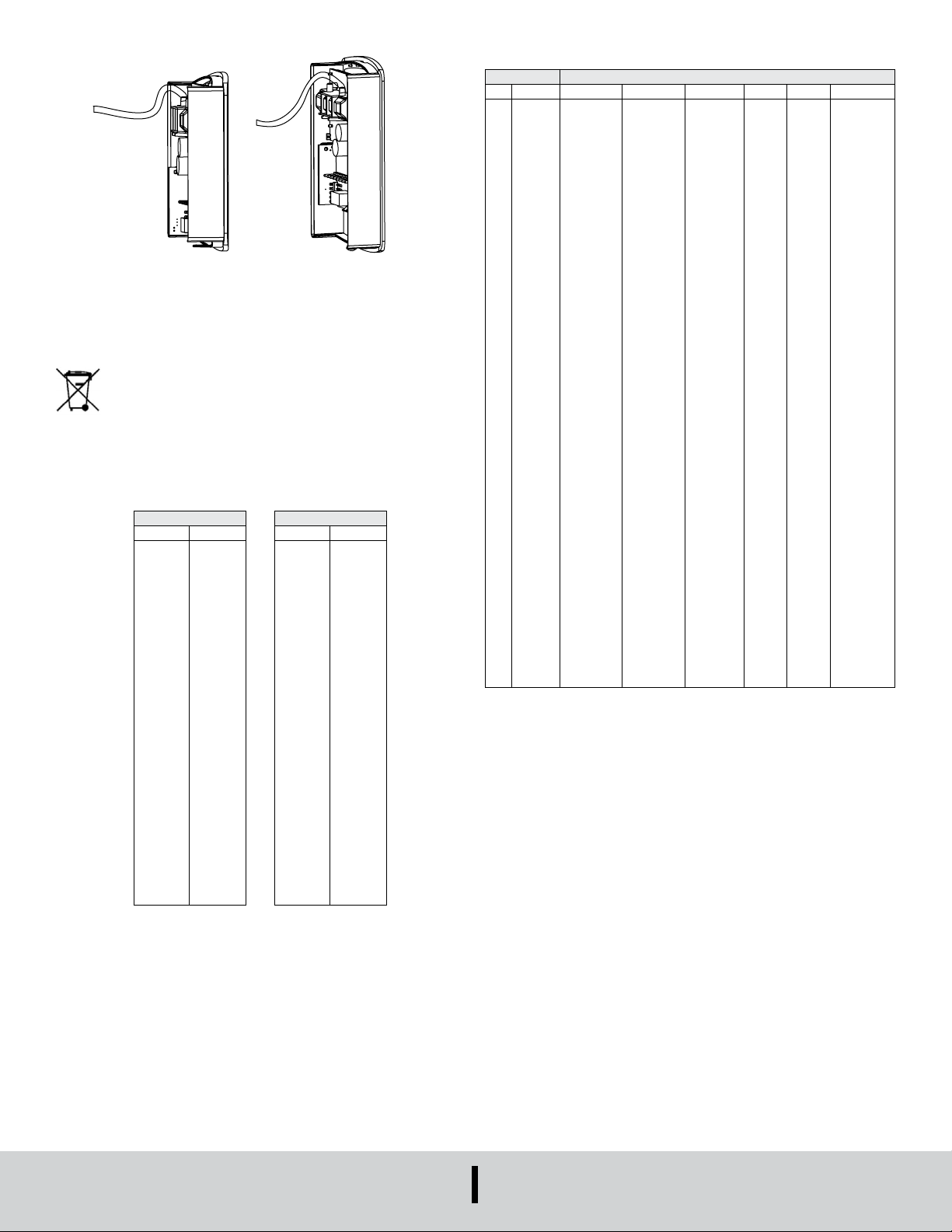
Figure 6: Calibration
MAINTENANCE/REPAIR
Upon nal installation of the Series CDT and CDTR, no routine maintenance is
required. The Series CDT and CDTR are not eld serviceable and should be returned
if repair is needed. Field repair should not be attempted and may void warranty.
This symbol indicates waste electrical products should not be disposed
of with household waste. Please recycle where facilities exist. Check with
your Local Authority or retailer for recycling advice.
WARRANTY/RETURN
Refer to “Terms and Conditions of Sales” in our catalog and on our website. Contact
customer service to obtain a Return Materials Authorization number (RMA) before
shipping the product back for repair. Be sure to include a brief description of the
problem plus any additional application notes.
US Customary Units
ft in Hg
0
400
800
1200
1600
2000
2400
2800
3200
3600
4000
4400
4800
5200
5600
6000
6400
6800
7200
7600
8000
8400
8800
9200
9600
10000
29.92
29.50
29.10
28.69
28.29
27.90
27.51
27.13
26.76
26.39
26.02
25.66
25.30
24.95
24.60
24.26
23.93
23.60
23.27
22.94
22.63
22.31
22.00
21.70
21.40
21.40
Figure 7: Elevation chart
North American
SI Units
m hPa
0
100
200
300
400
500
600
700
800
900
1000
1100
1200
1300
1400
1500
1600
1700
1800
1900
2000
2100
2200
2300
2400
2500
1013
1002
990
979
968
957
946
935
924
914
904
893
883
873
863
853
844
834
824
815
806
797
787
779
770
761
RESISTANCE VS TEMPERATURE TABLE
Temperature Resistance Curves (in Ω)
°C °F A B C D E F
-55
-67.0
-50
-45
-40
-35
-30
-25
-20
-15
-10
-5
0
5
10
15
20
25
30
35
40
45
50
55
60
65
70
75
80
85
90
95
100
105
110
115
120
125
130
135
140
145
150
-58.0
-49.0
-40.0
-31.0
-22.0
-13.0
-4.0
5.0
14.0
23.0
32.0
41.0
50.0
59.0
68.0
77.0
86.0
95.0
104.0
113.0
122.0
131.0
140.0
149.0
158.0
167.0
176.0
185.0
194.0
203.0
212.0
221.0
230.0
239.0
248.0
257.0
266.0
275.0
284.0
293.0
302.0
607800.00
441200.00
323600.00
239700.00
179200.00
135200.00
102900.00
78910.00
61020.00
47540.00
37310.00
29490.00
23460.00
18780.00
15130.00
12260.00
10000.00
8194.00
6752.00
5592.00
4655.00
3893.00
3271.00
2760.00
2339.00
1990.00
1700.00
1458.00
1255.00
1084.00
963849.00
670166.00
471985.00
336479.00
242681.00
176974.00
130421.00
97081.00
72957.00
55329.00
42327.00
32650.00
25392.00
19901.00
15712.00
12493.00
10000.00
8057.00
6531.00
5326.00
4368.00
3602.00
2986.00
2488.00
2083.00
1752.00
1480.00
1255.00
1070.00
939.30
816.80
712.60
623.60
547.30
481.80
425.30
376.40
334.00
297.20
265.10
237.00
Figure 8: Resistance vs temperature
915.50
786.60
678.60
587.60
510.60
445.30
389.60
341.90
301.00
265.80
235.30
208.90
186.10
289154.70
201049.80
141595.50
100943.70
72804.30
53092.20
39126.30
29124.30
21887.10
16598.70
12698.10
9795.00
7617.60
5970.30
4713.60
3747.90
3000.00
2417.10
1959.30
1597.80
1310.40
1080.60
895.80
746.40
624.90
525.60
444.00
376.50
321.00
274.65
235.98
203.58
176.28
153.18
133.59
116.88
102.57
90.30
79.74
70.59
62.67
55.83
78.32
80.31
82.29
84.27
86.25
88.22
90.19
92.16
94.12
96.09
98.04
100.00
101.95
103.90
105.85
107.79
109.74
111.67
113.61
115.54
117.47
119.40
121.32
123.24
125.16
127.08
128.99
130.90
132.80
134.71
136.61
138.51
140.40
142.29
144.18
146.07
147.95
149.83
151.71
153.58
155.46
157.33
783.2
803.1
822.9
842.7
862.5
882.2
901.9
921.6
941.2
960.9
980.4
1000.0
1019.5
1039.0
1058.5
1077.9
1097.4
1116.7
1136.1
1155.4
1174.7
1194.0
1213.2
1232.4
1251.6
1270.8
1289.9
1309.0
1328.0
1347.1
1366.1
1385.1
1404.0
1422.9
1441.8
1460.7
1479.5
1498.3
1517.1
1535.8
1554.6
1573.3
2394000.00
1646200.00
1145800.00
806800.00
574400.00
413400.00
300400.00
220600.00
163500.00
122280.00
92240.00
70160.00
53780.00
41560.00
32340.00
25360.00
20000.00
15892.00
12704.00
10216.00
8264.00
6722.00
5498.00
4520.00
3734.00
3100.00
2586.00
2166.00
1822.60
1540.00
1306.40
1112.60
951.00
815.80
702.20
606.40
525.60
N/A
N/A
N/A
N/A
N/A
LEED® is a registered trademark of the U.S. Green Building Council
©Copyright 2020 Dwyer Instruments, Inc. Printed in U.S.A. 9/20 FR# 443800-40
DWYER INSTRUMENTS, INC.
P.O. BOX 373 • MICHIGAN CITY, INDIANA 46360, U.S.A.
Phone: 219/879-8000
Fax: 219/872-9057
dwyer-inst.com
e-mail: [email protected]
 Loading...