

Page 1
2
e
o
TM
User’s Guide
Shop online at
omega.com
e-mail: [email protected]
For latest product manuals:
www.omegamanual.info
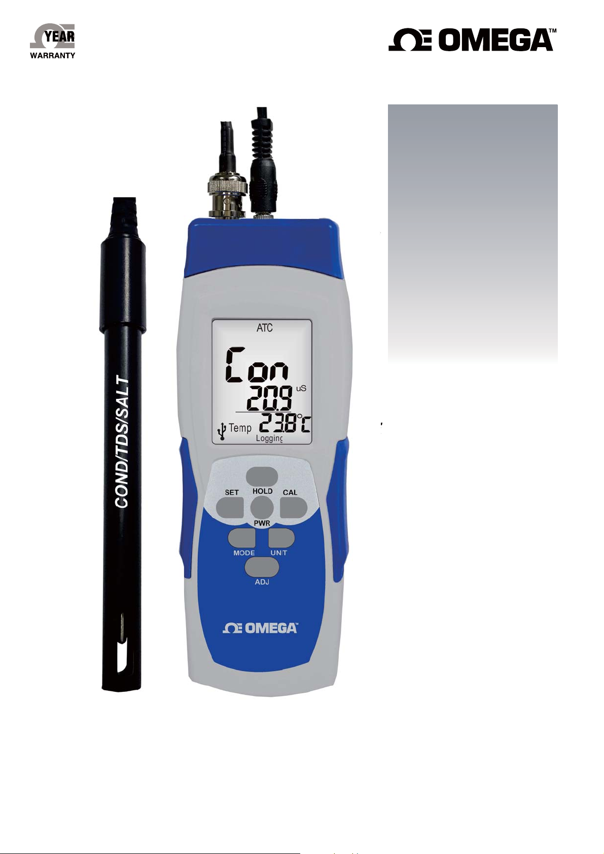
CDH-SD11
#ONDUCTIVITY4$3AND3ALINITY-ETERWITH2EAL4IME3$#ARD$ATA,OGGER
Page 2

omega.com [email protected]
Servicing North America:
U.S.A. Omega Engineering, Inc.
Headquarters: Toll-Free: 1-800-826-6342 (USA & Canada only)
Customer Service: 1-800-622-2378 (USA & Canada only)
Engineering Service: 1-800-872-9436 (USA & Canada only)
Tel: (203) 359-1660 Fax: (203) 359-7700
e-mail: [email protected]
For Other Locations Visit omega.com/worldwide
The information contained in this document is believed to be correct, but OMEGA accepts no liability for any errors it contains, and
reserves the right to alter specifications without notice.
Page 3
FEATURES
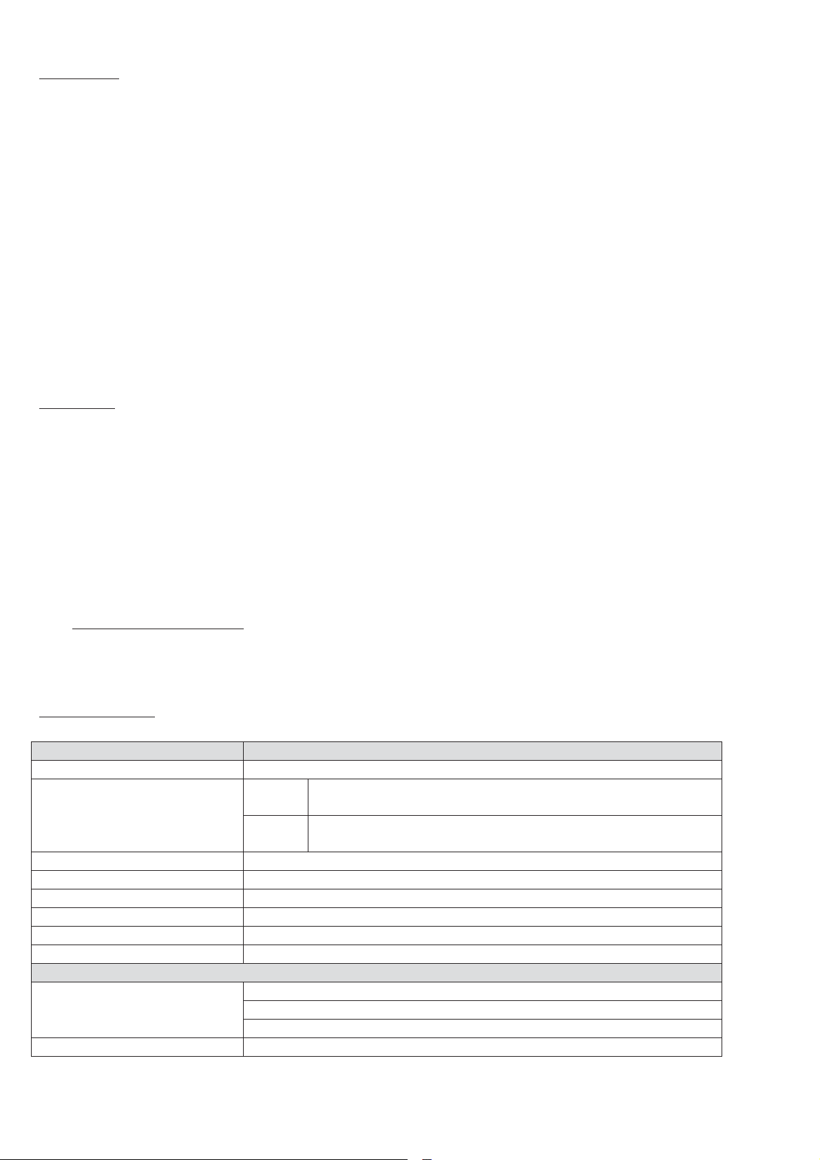
Model
CDH-SD11
Parameter
Cond./EC/TDS /Salt
Data logger sampling time
Setting range
Auto
0, 2 secs, 5 secs, 10 secs, 15 secs, 30 secs, 60 secs,
120 secs, 300secs, 600 secs, 900 secs, 1800 secs, 1Hr
Manual
Press the ADJ button once will save data one time.
Set the sampling time to 0 second.
Memory Card
SD memory card 8G
Data Hold
Freeze the display reading.
Meter dimension
175mm x 58mm x 32mm (With BNC connector)
Power supply
AAA batteries x 3 pcs / 9V AC/DC adaptor (optional)
Temperature
0~90ɗ
Temp. accuracy
±0.5 ɗ
Conductivity
Measurement range
30 uS/cm~20 ms/cm (K=1) Supplied
500 uS/cm ~199 mS/cm (K=10) Option
Accuracy
1) Professional look design accurate portable meters with large LCD display, with BNC connector.
2) All electrodes with BNC c
3) Hold function, low battery icon indicator, automatic power off in 15 minutes and may be disabled.
4) Built-in different temperature compensation selectable: Thermistor 30K, 10K ohm.
5) RFS (Recover to Factory Setting) function is included.
6) Conductivity calibration points: 1413uS. Calibration solution is included.
7) Conductivity electrode may convert to EC, TDS and Salinity concentration, Adjustable conductivity to TDS
conversion factor from 0.4 to 1.0. Three in one conductivity electrode (Cond/EC. TDS. Salinity)
measurement.
8) Conductivity cell constant (K) selectable: 1.0, (Standard) 10 (Optional) (Selectable and adjustable).
9) SD card capacity: 1GB to 8GB.
10) Tripod receptacle mountable design for long time monitoring purposes.
11) All sensors are well calibrated before shipment.
12) Warranty period of meter is two years. Electrode is one year.
SUPPLIED
z Meter
z Electrode x 1pc (Cond./EC/TDS/Salt)
z Battery-AAA x 3 pcs
z 1413uS buffer solution (Cond. K=1) x1 or 12.88mS buffer solution (Cond. K=10)
z 9V adaptor (optional)
z Black carrying case
z Operation manual
z 8G SD card
onnector compatible to any other electrodes.
ADDITIONAL PURCHSE
z CDE-11G K=1 electrode replacement (Graphite type)
z CDE-11P K=10 option (Platinum type)
SPECIFICATION
Page 4
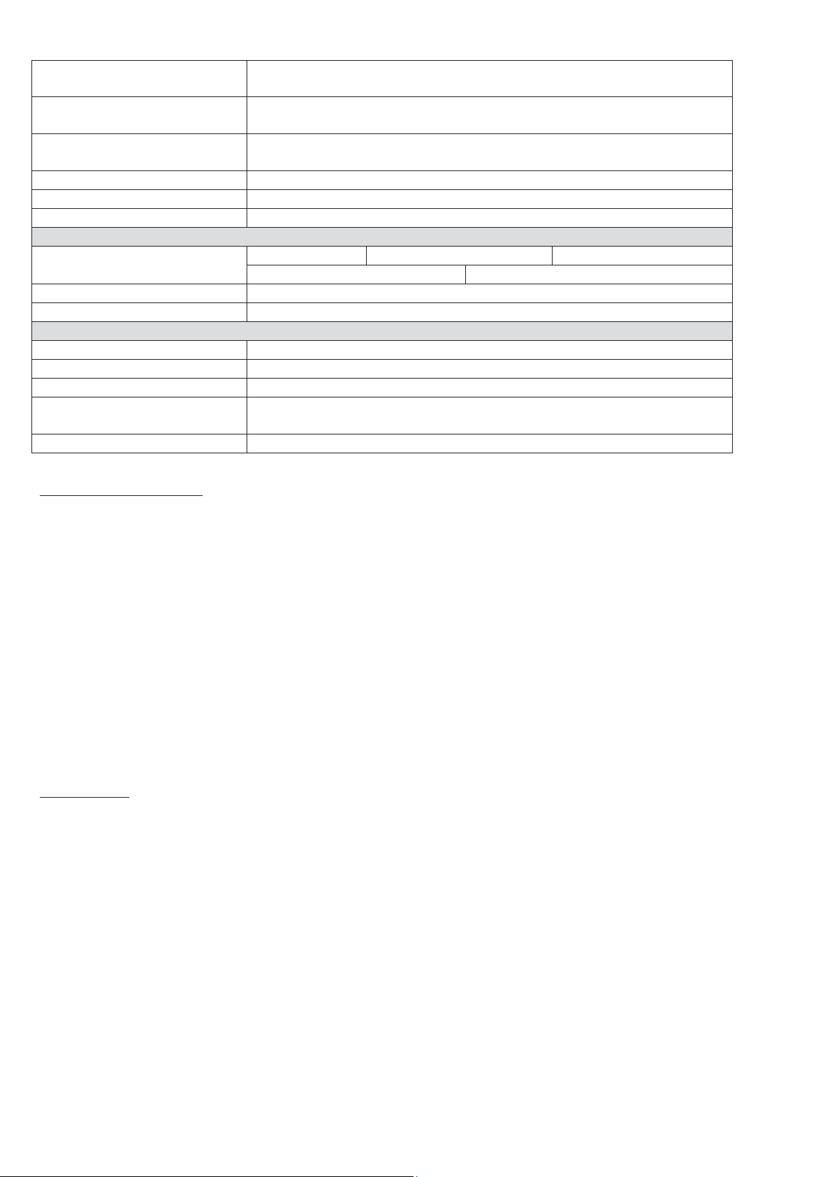
(±1% of full scale + 1 digit)
±199.71 (K=1)
±1985.01 (K=10)
Cond Calibration
1 point 1413 uS calibration (K=1)
1 point 12.8 mS calibration (K=10)
Resolution
0~1999 uS/cm (1)
Dimension
12x120mm
Electrode body
ABS
Sensor type
Graphite plate
TDS (Total Dissolved Solids)
Measurement range
0 to 19.99 ppm
0 to 199.9 ppm
0 to 1999 ppm
0 to 19.99 ppt
0 to 199.9 ppt
Accuracy
±1% of full scale + 1 digit
Resolution
0.01 ppm, 0.1 ppm, 1 ppm ; 0.01 ppt, 0.1 ppt
SALT
Measurement range
0~42.0 ppt (Sea water)
Accuracy
±1% of full scale + 1 digit
Resolution
0.1 ppt
ATC Temperature sensor
Probe port
Cable length
1 M
3.5 mm diameter phone jack
KEYPAD (CONTROLS)
PWR: Power on (Press in one second) or power off (Press more than 2 seconds when operation).
SET: Move to left digit. Short press to toggle COND ɦ EC ɦ!TDS ɦ Salt. Long pressing to save setting.
CAL: Move to right digit. To clear SD manual record data.
MODE: Select sample rate of SD card. Toggle Condɦt1Fɦtds (under K value adjustment mode).
Toggle 1413 uS calibration mode to 12.8 mS calibration mode (under Conductivity calibration mode).
UNIT: Short pressing to change temperature unit ɗ/ə. Long pressing to select temperature probe type.
Short pressing to select NTC: Negative Temperature Coefficient)/ NOT: no remote temperature probe.
HOLD: Freeze current readings (Hold shows at top of LCD). Increase value.
ADJ: Long press to start SD recording (SD card is inserted to the meter). Decrease value.
SET+UNIT: Enter cond. cell constant K value / Temp. coefficient compensation/tds K factor value mode.
Long press again to escape the K value setting. Recovery to factory setting (under calibration mode).
SET+CAL: Conductivity Calibration.
HOLD+PWR: Disable Auto Power Off.
OPERATION
COND/EC/TDS/SALT PROBE INSTALLATION (BNC connector):
a) Insert the COND electrode into the top of left hole. And insert the 3.5mm Ø diameter phone jack ATC
sensoring parts into the middle of hole.
b) Hold the BNC connector in one hand; with the other, insert the braid into the center of the connector.
Continuing pushing the braid into the connector until it will not go in any farther. Do this gently and slowly;
do not bend the braid.
c) Turn the BNC connector in a clockwise direction, until you cannot turn it any more.
Page 5
NOTE: Remove batteries when not use炰
ɗə
Pull down
T
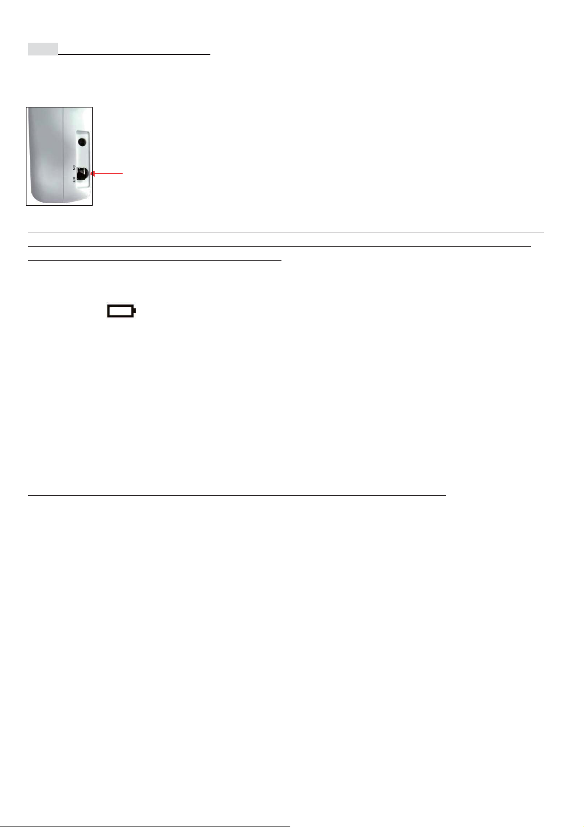
Power-off switch: When the meter is turned off, the internal CPU does not shut down completely, it will keep detecting
the buttons per milliseconds. Letting meter know if the user wants to activate the meter or not. It will consume the
power by each detecting, in order to save the power, you may pull down the switch.
he switch
127(
)RUHDFKRSHUDWLRQPDNHVXUH\RXDUHXVLQJIUHVKEDWWHULHVVDPHEUDQGVDPHSRZHURIEDWWHULHVLV
UHTXLUHGDQGRWKHUZLVHPHWHUVKRZVHUUDWLFUHDGLQJVRUOHDNDJH:DUUDQW\LVYRLGLIQRWIROORZWKH
QRWLFHV1RWH烉UHPRYHEDWWHULHVZKHQQRWXVH炰
7KHUHDUHWZRZD\VWRSURYLGHSRZHU
D$$$EDWWHULHV[SFV
E9$&'&DGDSWRURSWLRQDO
%DWWHU\LFRQLQGLFDWHVZKHQSRZHULVZHDNUHSODFHZLWKQHZEDWWHULHVLPPHGLDWHO\DVWKHUHDGLQJV
QRZRQ/&'DUHLQFRUUHFWGXHWRZHDNSRZHU
S%DWWHU\OLIH$SSUR[KRXUVIRUFRQWLQXRXVXVHG$SSUR[KRXUVIRUDFWLYDWLQJ6'IXQFWLRQZ
VDPSOHUDWHVHFRQGV$SSUR[KRXUVIRUDFWLYDWLQJ6'IXQFWLRQZVDPSOHUDWHKUV
)RUVKRUWWLPHPHDVXUHPHQW\RXPD\SRZHURQE\EDWWHULHV)RUORQJWLPHXVH\RXKDYHWRFRQQHFWZLWK
DQ$&'&DGDSWRU
0DNHVXUHVHQVRUSUREHDQGPHWHUDUHZHOOFRQQHFWHG'RQ¶WDWWHPSWWRGHWDFKVHQVRUSUREHIURPPHWH
ZKLOHLQRSHUDWLRQ
:KHQ0HWHUVKRZVHUUDWLFUHDGLQJVLWPXVWEHVHQVRUIDLOHGRUSRZHULVZHDN
2QO\VHOHFWRQHRIWKHWZRHOHFWURGHVZKLOHPHDVXULQJWKHVDPHZDWHU]RQHRWKHUZLVHPHWHUDSSHDUVHUUDWLF
UHDGLQJV5HDGWZRSDUDPHWHUVDWWKHVDPHWLPHDUHRQO\DYDLODEOHIRUPHDVXULQJWZRGLIIHUHQWZDWHUVRXUFHV
U
32:(5
127(0DNHVXUH\RXKDYHFRQQHFWHGWKHHOHFWURGHWRWKHPHWHUEHIRUHSRZHURQ
0RPHQWDULO\SUHVVLQJ3:5EXWWRQWRWXUQRQWKHPHWHUSUHVVDQGKROG3:5EXWWRQVWRWXUQRIIPHWHU
&21'(&7'66DOW02'(
6KRUWSUHVVLQJ6(7EXWWRQWRWRJJOH&21' ɦ(&ɦ7'6ɦ6DOW
&+$1*(7+(7(0381,772
6KRUWSUHVVLQJ81,7EXWWRQWRWRJJOH ɗRUə
+2/'
)UHH]HWKHFXUUHQWUHDGLQJVRI&RQG(&7'66DOWWKHQLFRQ³+ROG´ZLOODSSHDURQWKHWRSOHIWRIVFUHHQ
$87232:(52))
0HWHUZLOOWXUQRIIDXWRPDWLFDOO\LQPLQXWHVZKHQQRXVHWRGLVDEOHDXWRSRZHURIIIXQFWLRQE\SUHVVLQJ
+2/'DQG3:5EXWWRQV³Q´PRPHQWDULO\VKRZVRQVFUHHQQRZPHWHULVDWQRQVOHHSPRGHWKHQWXUQVWR
QRUPDOPHDVXUHPHQW0HWHUGHIDXOWDXWRSRZHURII
Page 6
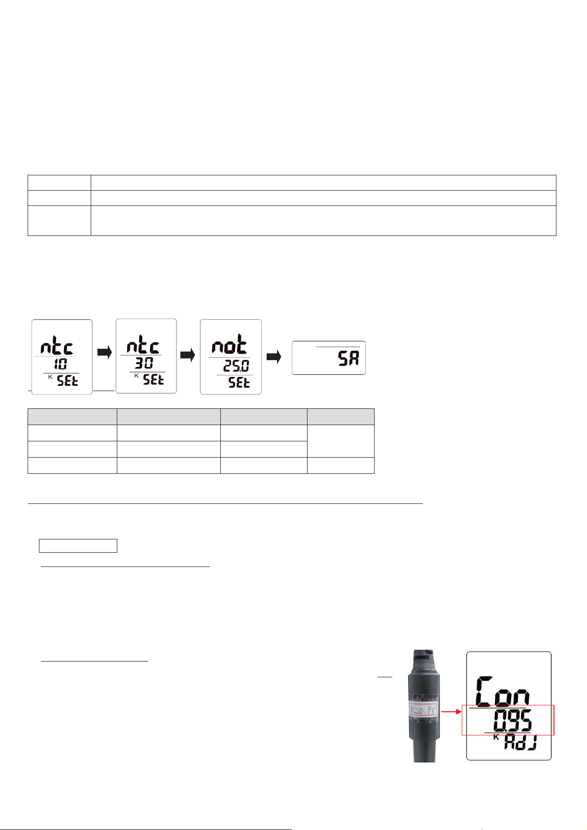
(6) FACTORY RESET
NTC 10K:
Negative Temperature Coefficient 25ɗ = 10 K
NTC 30K:
Negative Temperature Coefficient 25ɗ = 30 K
NOT:
External temperature probe is excluded, user can enter the temperature degree by their own
temperature instrument, default: 25ɗ Adjustable range: 0.0ɗ~90.0ɗ
Probe type
ntc 10K (Default)
ntc 30K
not
Plug in
Te mp. X X. X
Te mp. X X. X
Manual
temp.
Un-plugged
“ʇġ ʇġ ʇ”
“ʇġ ʇġ ʇ”
AT C i co n
O
O
X
a) Cond. electrode
Whenever replacing a new cond. electrode. Long pressing SET+CAL buttons to enter Cond. calibration mode
then strongly recommend doing factory reset by pressing SET+UNIT under 1413 uS calibration mode, screen
will show “rFS” momentarily.
(7) TEMPERATURE PROBE TYPE SELECTION
NOTE: If using NTC 10K probe but select 30K type. The temperature value will not be accurate.
Default setting is NTC 10K. User can change it depends on the electrode type to get the correct value.
Step 1: Must select correct probe type before measurement, otherwise the value would be incorrect.
Step 2: Long pressing UNIT button, the meter default is “ntc 10k”, short pressing UNIT button to toggle ntc 30k
ɦ not.
Step 3: Long pressing UNIT button again to save the setting, meter shows “SA” at the bottom of LCD and then
return to normal measurement mode.
“ATC” ICON INDICATION
CONDUCTIVITY/EC/TDS/SALT CALIBRATION PROCEDURE and MEASURING
NOTE: Calibration is necessary before operation, the calibration procedures refer to as below “ a) to b)”:
2-1 Conductivity
a) Required Equipment for calibration:
1) Cond./EC/TDS/SALT ELECTRODE
2) Prepare the standard 1413 uS conductivity solution.
Toggle 1413 uS calibration mode to 12.8 mS calibration mode (under Conductivity calibration mode).
NOTE: Make sure to use fresh solution each time due to the contaminants in the solution will affect
the calibration and the accuracy.
b) Calibration Procedure:
1) Prepare the Conductivity electrode, install the “electrode plug” into the left
“BNC port” of the meter.
2) Power on the meter by pressing PWR button.
3) First, to enter the cell constant (K) value of the Cond. electrode is required
(e.g. Refer to the label on the top handle of the probe.)
Page 7
Long pressing SET+UNIT buttons to enter the cell constant value. Units digit will flash.
HOLD: ɥto increase ADJ: ɧto decrease SET: ɤ to left digit CAL: ɦ to right digit
And long pressing SET to save setting, screen will show “SA”.
To escape calibration mode without saving setting, long pressing SET+UNIT buttons, the bottom of screen
will show “ESC” few seconds and return to normal measurement mode.
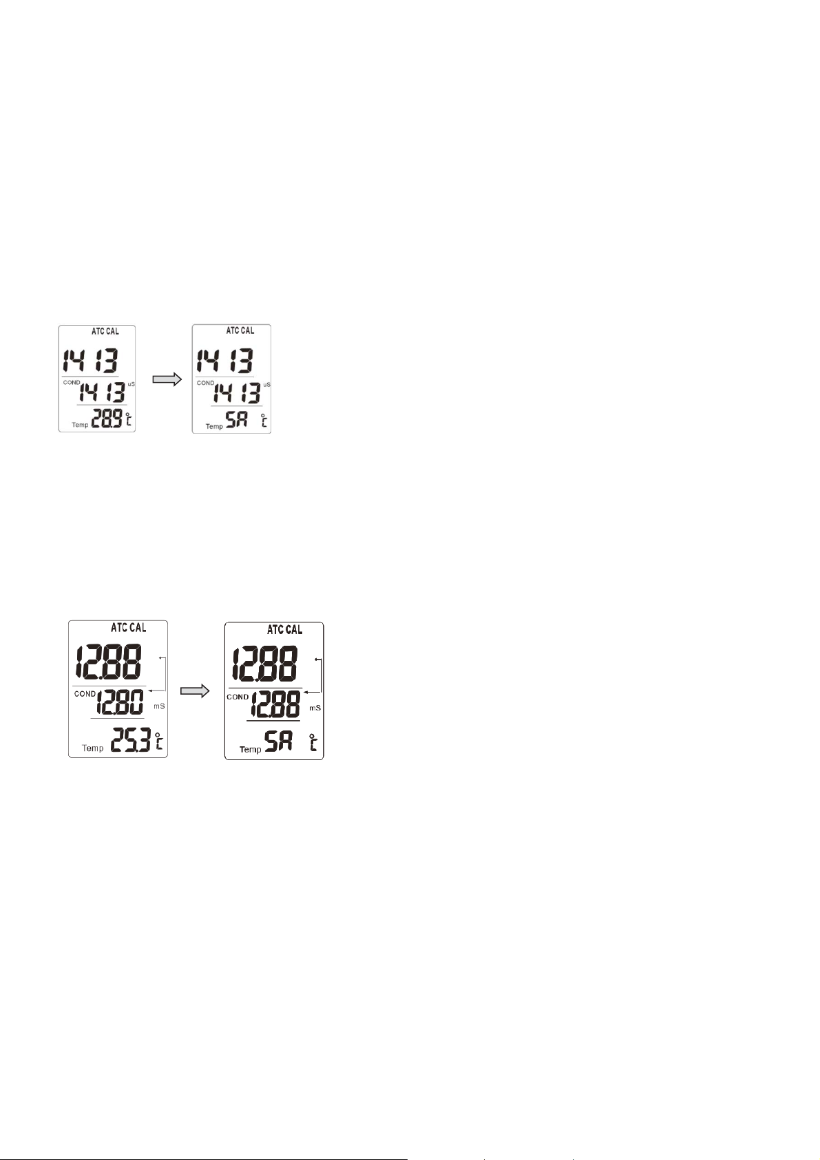
4) Conductivity electrode (K = 1):
Long pressing SET + CAL buttons to enter Cond. calibration mode. Immerse the cond. probe to standard
1413 uS buffer solution. Display will show the standard conductivity 1413 uS values. Long pressing SET
button to finish calibration, screen will show “SA”. To escape calibration mode without saving setting, long
pressing SET+CAL buttons, the bottom of screen will show “ESC” few seconds and return to normal
measurement mode.
Conductivity electrode (K=10):
Long pressing SET + CAL buttons to enter Cond. calibration mode. Short pressing MODE button to enter
12.8 mS calibration mode. Immerse the cond. probe (K=10) to standard 12880 us/cm buffer solution. Display
will show the standard conductivity 12.8 mS value in the first layer. Long pressing SET button to finish
calibration, screen will show “SA”.
To escape calibration mode without saving setting, long pressing SET+CAL buttons, the bottom of screen will
show “ESC” few seconds and return to normal measurement mode.
NOTE: The display shows 12.88 means 12.88 mS (12880 uS/cm).
5) Change the temp. coefficient is necessary. Default setting is 2.01% per ɗ.
Using a suitable temp. coefficient of the solution will provide good results.
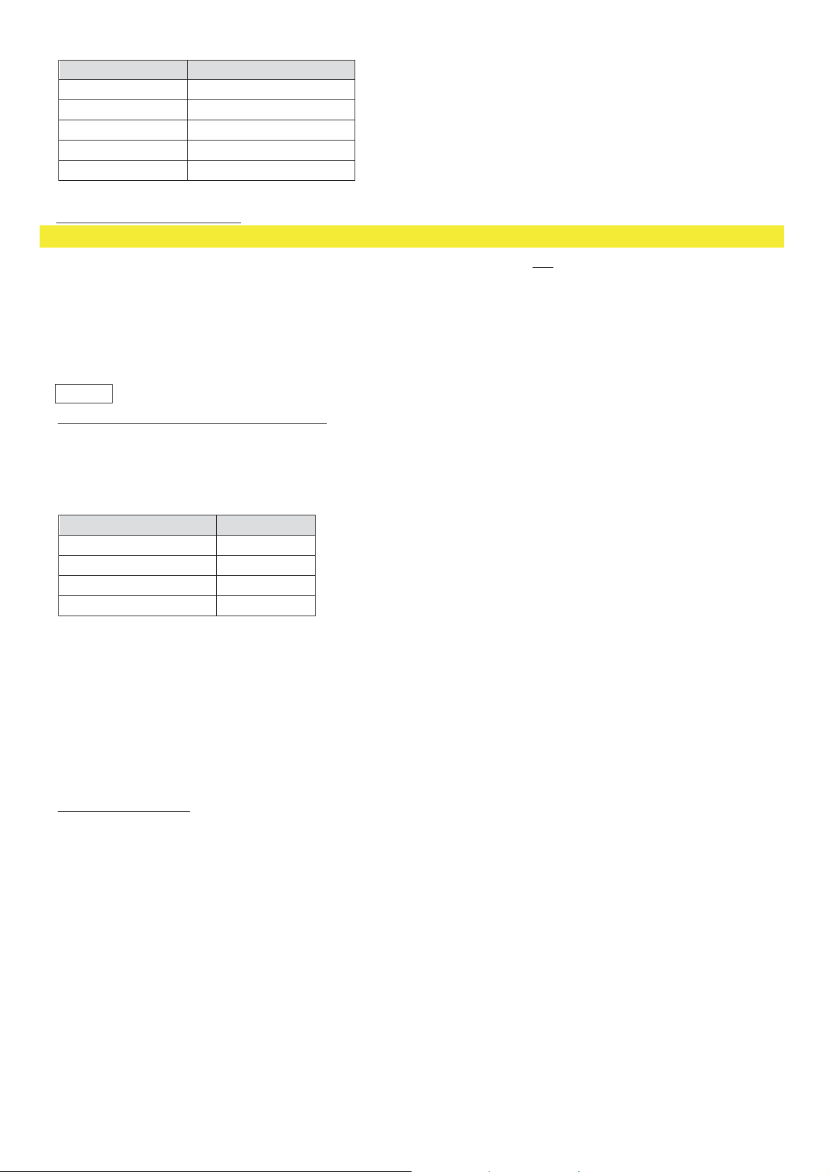
The temp. coefficients of the following electrolytes generally fall into the ranges shown below:
To enter the temperature coefficients by long pressing SET+UNIT buttons, then short pressing MODE to
toggle Con´t I F´tdS. And go to select “t I F” and set the value.
HOLD: ɥto increase ADJ: ɧto decrease SET: ɤ to left digit CAL: ɦ to right digit
Long pressing SET button to finish calibration, screen will show “SA” .The adjustable range is 1% to 7.4%.
Or to escape setting by long pressing SET+UNIT buttons, the bottom of screen will show “ESC” in few
seconds and return to normal measurement mode.
Page 8
Solution
Temp. Coefficients
Acids
1.0 - 1.6% / ɗ
Bases
1.8 - 2.2% / ɗ
Salts
2.2 - 3.0% / ɗ
Drinking water
2.0% / ɗ
Ultrapure water
5.2% / ɗ
c) Conductivity measurement:
Solution
Factor
Water
0.55~0.8
Drinking water
0.64
Absolute pure water
0.055
Distilled water
0.5 ~ 1.0
NOTE: For measuring high conductivity reading such as seawater, ensure to purchase cond. electrode (K=10).
1) Prepare the Conductivity electrode, install the “electrode plug” into the left “BNC port” of the meter.
2) Power on the meter by short pressing PWR button.
3) Hold the electrode handle by hand and let the sensing head immersed wholly into the measured solution.
Shake the probe to let the probe’s internal air bubble drift out from the sensing head.
Display will show the conductivity mS (uS) values.
2-2 TDS
a) Calibration by using Conversion Factors
TDS values are related to conductivity. To calibrate the meter by using conductivity standards as described
in 2-1-b (Page 6) and select the correct TDS conversion factor. You can refer to below table or calculate the
TDS conversion factor for other solutions by using the formula. Meter default is 0.66.
Factor= Actual TDS ÷ Actual Conductivity @ 25 ɗ
To enter the factor by long pressing SET+UNIT buttons, then short pressing MODE to toggle Con´t I F´tdS.
And go to select “tdS”and set the value.
HOLD: ɥto increase ADJ: ɧto decrease SET: ɤ to left digit CAL: ɦ to right digit
Long pressing SET button to finish calibration, screen will show “SA”. The adjustable range is 0.05 to 1.00.
Or to escape setting by long pressing SET+UNIT buttons, the bottom of screen will show “ESC” few seconds
and return to normal measurement mode.
b) TDS measurement:
1) Under normal measurement mode, short pressing SET button to toggle Cond. measurement to TDS
measurement.
2) The measuring procedures are same as above 2-1-c (page 7) conductivity measurement, except to change
the display unit from uS, mS to PPM, PPT.
Display will show TDS values at the same time the left bottom display will show the temp. value of the
measured solution.
NOTE: If the TDS value is ppm, the conductivity value must be in uS ; if the TDS value is in ppt, the
conductivity value must be in mS.
Page 9
2-3 Salt
ɗɗ əə μS/cm
ɗɗ əə μS/cm
ɗɗ əə μS/cm
0
32
33.8
35.6
37.4
39.2
42.8
44.6
46.4
48.2
51.8
53.6
55.4
57.2
60.8
776
799
822
846
870
894
918
943
968
992
1017
1043
1068
1094
1119
1145
1171
17
62.6
64.4
66.2
69.8
71.6
73.4
75.2
78.8
80.6
82.4
84.2
87.8
89.6
91.4
1198
1224
1251
1277
1304
1331
1358
1386
1413
1441
1468
1496
1524
1552
1580
1608
1636
34
93.2
96.8
98.6
100.4
102.2
104
105.8
107.6
109.4
111.2
113
114.8
116.6
118.4
120.2
122
1665
1693
1722
1751
1780
1808
1837
1866
1896
1925
1954
1983
2013
2042
2071
2101
2103
a) Calibration
If the conductivity range already makes the calibration completely (refer to 2-1-b at page 6 ) then the salt
measurement is not necessary to make the calibration again.
b) Salt measurement
1) Under normal measurement mode, short pressing SET button to toggle Cond. measurement to “salt”
measurement mode.
2) Hold the Cond. electrode handle by hand and let the sensing head Immersed wholly into the measured
solution. Shake the probe to let the electrode’s internal air bubble drift out from the sensing head.
Display will show salt values (ppt) at the same time the left bottom display will show the temp. value of the
measured solution.
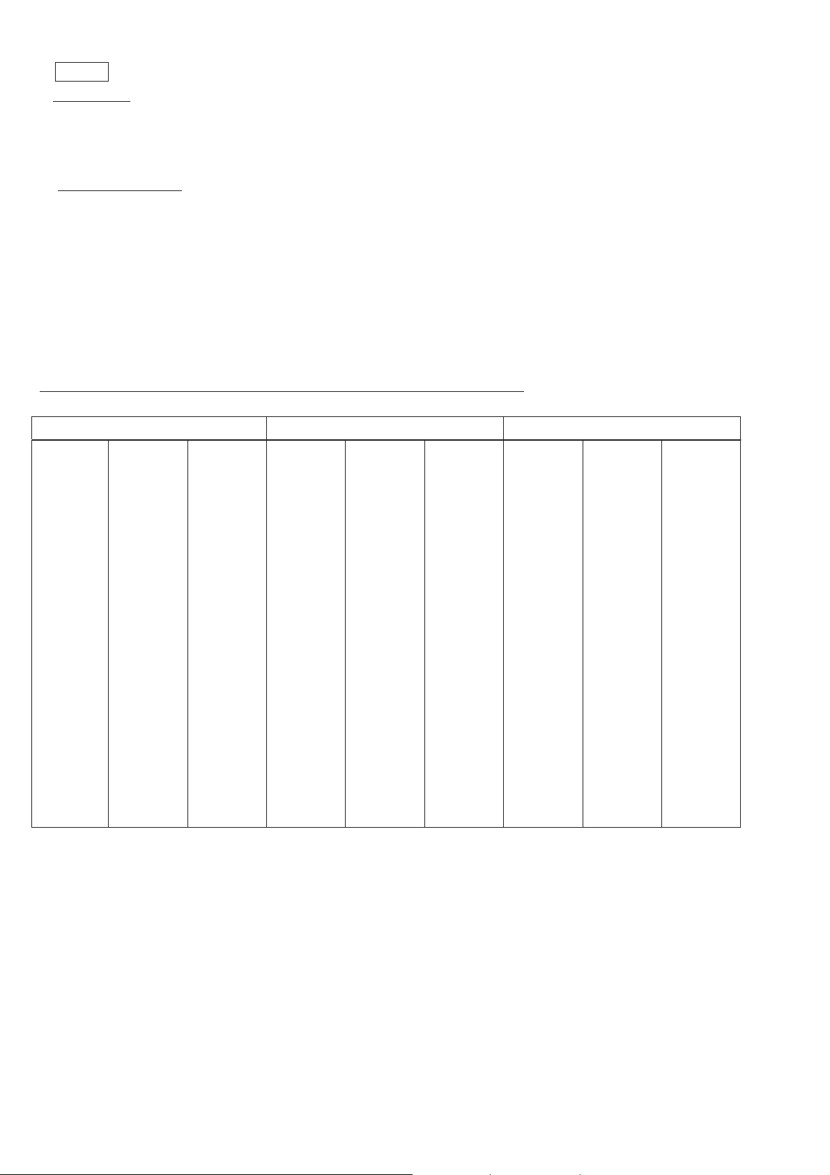
CONDUCTIVITY STANDARD SOLUTION (K=1) (1413 μS/cm at 25°C)
ɈConductivity reading will be affected by the temperature.
1
2
3
4
5
6
7
8
9
10
11
12
13
14
15
16
41
50
59
18
19
20
21
22
23
24
25
26
27
28
29
30
31
32
33
68
77
86
35
36
37
38
39
40
41
42
43
44
45
46
47
48
49
50
95
Page 10
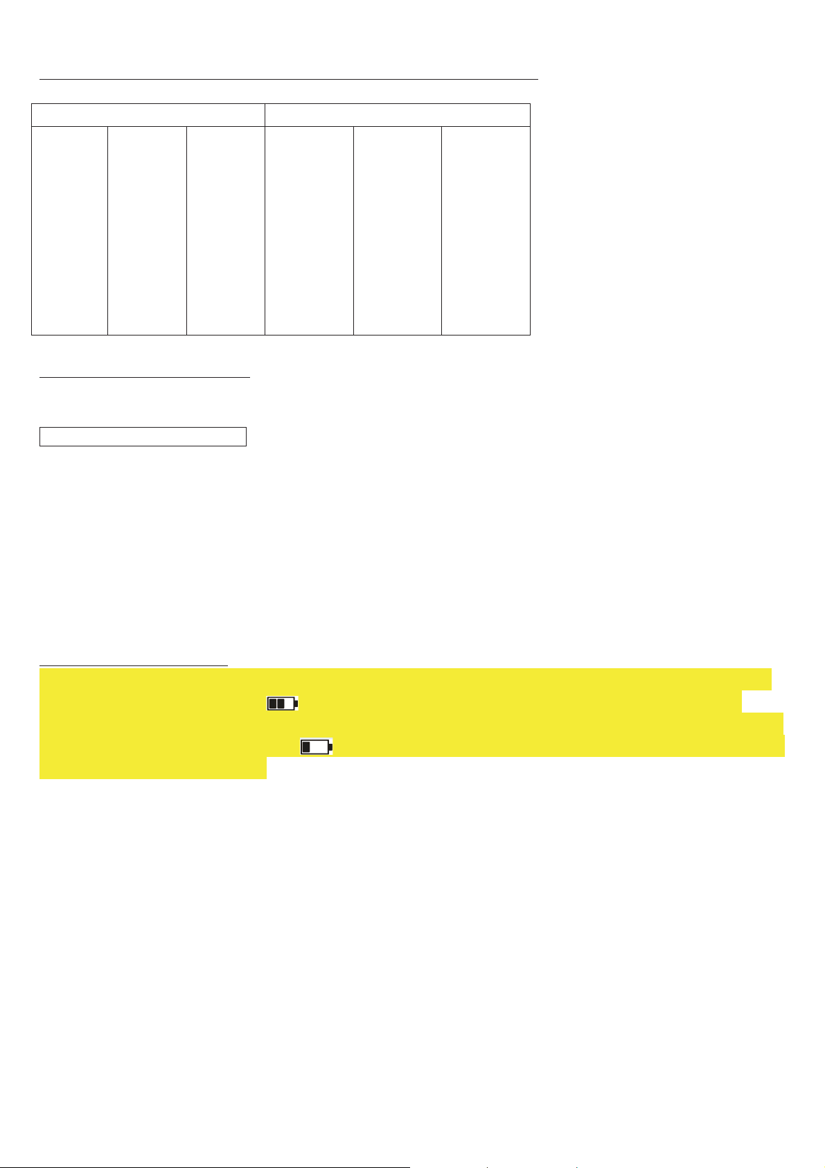
CONDUCTIVITY STANDARD SOLUTION (K=10) (12880 μS/cm at 25°C)
ɗɗ əə μS/cm
ɗɗ əə μS/cm
5
10
15
16
17
18
19
20
21
41
50
59
60.8
62.6
64.4
66.2
68
69.8
8,216
9,326
10,439
10,684
10,929
11,174
11,419
11,664
11,909
22
23
24
25
30
35
40
45
50
71.6
73.4
75.2
77
86
95
104
113
122
12,153
12,398
12,643
12,880
14,112
15,392
16,678
18,024
19,338
ɈConductivity reading will be affected by the temperature.
ELECTRODE MAINTENANCE
Proper maintenance will ensure faster measurements, improve accuracy and extend the lifetime of
the electrode.
Cond./EC/ TDS /Salt electrode
Conductivity meters and cells should be calibrated to a standard conductivity solution. Selecting standards is
very important, you should always choose one that has the approximate conductivity of the solution to be
measured.
A polarized or fouled electrode must be cleaned to renew the active surface of the cell.
In most situations, hot water with a mild liquid detergent is an effective cleanser.
Acetone easily cleans most organic matter, and hypochlorous solutions will remove algae,bacteria, or molds.
To prevent cell damage, abrasives or sharp objects should not be used to clean an electrode.
A cotton swab also works well for cleaning.
SD CARD DATA LOGGING
ɈAfter inserting the SD card, the “SD” icon will appear on the bottom of display. When the meter supplied by
batteries, once the icon becomes with SD icon disappeared, it indicates the power is not enough to
activate SD function but other functions are still working, now we suggest the user to use adaptor to power the
meter. Once the battery icon becomes , it means the power is very weak, and should be replaced the new
batteries for operating the meters.
z SD Card Information
a) Power the meter with AAA batteries or 9V AC/DC adaptor (optional).
b) Insert an SD card (8G supplied) into the SD card slot at the right side of the meter. The card must be
inserted with the front of the card (label side) facing toward front of the meter.
After inserting the SD card, icon “SD” will appear on the bottom of screen.
c) If the SD card is being used for the first time it is recommended that the card be formatted.
Page 11
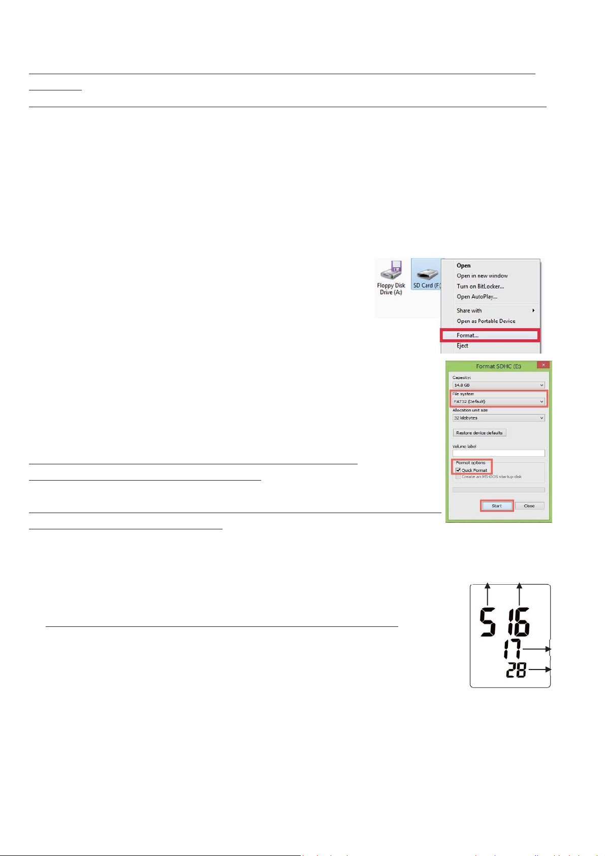
z SD Card Formatting
Month
Date
Hour
Minute
NOTE: Always confirm that the device is compatible with the SD, SDHC or SDXC memory card befo
re
formatting.
WARNING: Backup all your data before formatting. Formatting will erase all data on the memory device.
a) Open the Computer window.
Click the Start or Windows menu and select Computer (Windows Vista/7) or My Computer (Windows XP). Fo
dows 8 users, type “computer” and click the Computer icon in the Apps search results. For Windows 10,
Win
r
open the File Explorer. Then find “This PC”.
b) Find your SD card.
The removable drive that appears last in the "Devices with Removable Storage" list should be the SD card that
you just connected to your computer. Right-click on your SD card to bring up the right-click menu options. Select
Format. This will take you to the Format window. Keep “Capacity” and “Allocation unit size” set to default.
c) Select the file system.
This is the way files are stored on the card. Different systems
use different file structures. In order for the SD card to be read
by any device, select FAT32 as the file system. This will enable it t
o
be read by cameras, phones, printers, Windows, Mac, and Linux
compute
rs, and more.
1. Select Quick Format.
2. Click “Start”.
3. Once the formatting is complete, you can close the window.
z Automatic Data logging
The meter stores a reading at a user-selected sampling rate ont
D memory card. The meter defaults to a sampling rate of 2 seconds.
S
o an
NOTE: The sampling rate cannot be “0” for automatic data logging.
NOTE: Plug in the adaptor for SD data logging.
Setting the data logger clock time
NOTE: Make sure the clock of the meter is set up correctly in order to get accurate
date/time during data logging sessions.
1. Power OFF the meter, pressing MODE+POWER buttons to enter setting. YEAR digit “18” will flash.
2. Short pressing CAL go to Month´Day´ Hour´ Minute setting.
3. Press and hold SET button to save setting and screen will show “SA” then “End”.
4. Re-power ON the meter to back to normal measurement mode.
NOTE: To escape setting by turning OFF the meter without any change.
a) Setting the data logger sampling rate
1. While meter is power ON, press and hold MODE button to enter setting.
2. Pressing HOLD button to increase the value; pressing ADJ to decrease the value.
3. Long pressing MODE button to save setting.
4. The available settings are: 0, 2 sec, 5 sec, 10 sec, 15 sec, 30 sec, 60 sec, 120 sec, 300 sec, 600 sec,
900 sec, 1800 sec, and 1hr.
Page 12

b) Start data logging
Warning: SD recording the selected temperature unit (ɗorə). If changing the temperature unit
during the data logging sessions, the recorded data will be switched into the selected temperature unit.
1. Power on the meter by AAA batteries or 9V AC/DC adaptor (optional).
2. After inserting the SD card, display will show icon “SD” on the bottom of the screen.
3. Long pressing ADJ button to starts recording until icon “SD” flashing on the bottom of screen.
4. When “SD” disappears, SD stop to record data or SD card is not being inserted.
5. When an SD card is used for the first time a folder is created on the card and named the model number.
Under the MODEL number folder, the MODEL number and AUTO+YEAR folder will be automatically
created. e.g.: /CDH-SD11/AUTO2017/…..
6. When data logging begins, a new folder named M(month)/D(date)/H(hour)/M(minute) is created on the
SD card in the AUTO+YEAR folder. At the same time, a new spreadsheet document (CSV.) named
M/D/H/M is also created under its folder.
e.g.: /CDH-SD11/AUTO2017/04051858/04051858.csv
7. Each CSV. file can be stored up to 30,000 points.
After reaching 30,000 points, a new file name will be auto created as M/D/H/M right after the last
recording time. Unless you interrupt the recording, this process continues in the initial created M/D/H/M
folder.
e.g.: /CDH-SD11/AUTO2017/12261858/12262005.csv
NOTE1: Data logging stopped when replacing the probe, removing the SD card, removing batteries,
adaptor or resetting the sampling rate.
NOTE2: When the recording is been stopped, a new folder will be created as M/D/H/M from the next
data logging.
NOTE3: When the recording year and model number is changed, the new folder will be also created
accordingly.
NOTE4: When SD card records 1 points, “SD” icon will flash one time, once the “SD” icon flashes three
times, it means the meter is under low battery, the recording will be failed if the battery is low.
z Manual data logging (MAX 199 points)
1. Set the sampling rate to “0” seconds (Refer to “Setting the data logger sampling rate”).
2. In the manual mode, data is logged when press and hold ADJ button and screen shows recorded points
“00X” in the temp. block with icon “MEM” flash in few seconds.
e.g. Recorded 1 points, then bottom screen shows “001”.
3. Long pressing CAL button to clear data (removed MANUAL.csv), screen shows “CLr”.
NOTE: While screen shows “Err” by long pressing CAL, it stands for no data can be cleared or SD card
isn’t being inserted.
NOTE: Once clear the data by long press CAL, there is no way to recover the data. If you want to keep
the previous data, rename the file “MANUAL.csv” in /CDH-SD11/ MANUAL.csv is required.
4. Data directory in SD card : /98717AT/ MANUAL.csv
NOTE: When manual data records full (199 points), logging will continue, but with new data overwriting
old. If you want to keep the previous data, rename the file “MANUAL.csv” in /CDH-SD11/ MANUAL.csv
is required.
Page 13
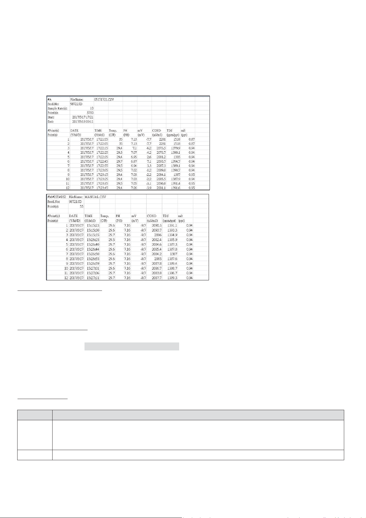
z SD Data Transfer to PC
Code
Description
--
The electrode were not in a solution. Dashes in the temp. mode indicates that probe without
ATC or manual temp. setting. The electrode of cond. measured in pure water or ultra pure water.
Select the wrong temp. probe type (refer to page 4).
OL2
Measurement is out of range of the display.
S Manual Data loggingS
Automatic Data logging
a) Remove the SD card from the meter.
b) Insert SD card directly into a PC SD card slot or use a SD card reader.
c) Open the saved documents (CSV.) in the folder from the PC to get the data.
d) File name /Product number/ Sample rate/ Recording point/ Start recording time/ End recording time/
Recording date/time /Recording parameters will be shown in the CSV. file.
e) Data show “0” stands for no measured value during recording period.
S
S
BURN OUT NOTIFICATION
If the sensor is not connected or over measurement range, the ˬ---˭will be displayed on LCD and the data in
the SD card is “0”.
TROUBLE SHOOTING
Q1: Wrong temperature??
A1: Refer to page 4 (TEMPERATURE PROBE TYPE), you must select the correct temperature sensor type or
adjust temperature manually (Long press UNIT button then press UNIT to select “not”).
Q2: Appear “Error codes”??
A2: Make sure if Hold appears on LCD.
ERROR CODES
-
Page 14

WARRANTY/DISCLAIMER
OMEGA ENGINEERING, INC. warrants this unit to be free of defects in materials and workmanship
for a period of 25 months from date of purchase. OMEGA’s WARRANTY adds an additional one (1)
month grace period to the normal two (2) year product warranty to cover handling and shipping
time. This ensures that OMEGA’s customers receive maximum coverage on each product.
If the unit malfunctions, it must be returned to the factory for evaluation. OMEGA’s Customer Service
Department will issue an Authorized Return (AR) number immediately upon phone or written request.
Upon examination by OMEGA, if the unit is found to be defective, it will be repaired or replaced at no
charge. OMEGA’s WARRANTY does not apply to defects resulting from any action of the purchaser,
including but not limited to mishandling, improper interfacing, operation outside of design limits,
improper repair, or unauthorized modification. This WARRANTY is VOID if the unit shows evidence of
having been tampered with or shows evidence of having been damaged as a
result of excessive corrosion; or current, heat, moisture or vibration; improper
specification; misapplication; misuse or other operating conditions outside of
OMEGA’s control. Components in which wear is not warranted, include but are not
limited to contact points, fuses, and triacs.
OMEGA is pleased to offer s
OMEGA neither assumes responsibility for any omissions or errors nor
assumes liability for any damages that result from the use of its products
in accordance with information provided by OMEGA, either verbal or
written. OMEGA warrants only that the parts manufactured by it will be as
specified and free of defects. OMEGA MAKES NO OTHER WARRANTIES OR
REPRESENTATIONS OF ANY KIND WHATSOEVER, EXPRESS OR IMPLIED, EXCEPT
THAT OF TITLE, AND ALL IMPLIED WARRANTIES INCLUDING ANY WARRANTY OF
MERCHANTABILITY AND FITNESS FOR A PARTICULAR PURPOSE ARE HEREBY
DISCLAIMED. LIMITATION OF LIABILITY: The remedies of purchaser set forth herein are
exclusive, and the
based on contract, warranty, negligence, indemnification, strict liability or otherwise,
shall not exceed the purchase price of the component upon which liability
is based. In no event shall OMEGA be liable for consequential, incidental or special damages.
CONDITIONS: Equipment sold by OMEGA is not intended to be used, nor shall it be used: (1) as a
“Basic Component” under 10 CFR 21 (NRC), used in or with any nuclear installation or activity; or (2)
in medical applications or used on humans. Should any Product(s) be used in or with any nuclear
installation or activity, medical application, used on huma
no responsibility as set forth in our basic WARRANTY / DISCLAIMER language, and, additionally,
purchaser will indemnify OMEGA and hold OMEGA harmless from any liability or damage whatsoever
arising out of the use of the Product(s) in such a manner.
total liability of OMEGA with respect to this order, whether
uggestions on the use of its various products. However,
ns, or misused in any way, OMEGA assumes
RETURN REQUESTS/INQUIRIES
Direct all warranty and repair requests/inquiries to the OMEGA Customer Service Department.
BEFORE RETURNING ANY PRODUCT(S) TO OMEGA, PURCHASER MUST OBTAIN AN AUTHORIZED
RETURN (AR) NUMBER FROM OMEGA’S CUSTOMER SERVICE DEPARTMENT (IN ORDER TO AVOID
PROCESSING DELAYS). The assigned AR number should then be marked on the outside of the return
package and on any correspondence.
The purchaser is responsible for shipping charges, freight, insurance and proper packaging to prevent
breakage in transit.
FOR WARRANTY RETURNS, please have the
following information available BEFORE
contacting OMEGA:
1. Purchase Order number under which the
product was PURCHASED,
2. Model and serial number of the product under
warranty, and
3. Repair instructions and/or specific problems
relative to the product.
OMEGA’s policy is to make running changes, not model changes, whenever an improvement is possible. This affords
our customers the latest in technology and engineering.
OMEGA is a trademark of OMEGA ENGINEERING, INC.
© Copyright 2018 OMEGA ENGINEERING, INC. All rights reserved. This document may not be copied, photocopied,
reproduced, translated, or reduced to any electronic medium or machine-readable form, in whole or in part, without the
prior written consent of OMEGA ENGINEERING, INC.
FOR NON-WARRANTY REPAIRS,
for current repair charges. Have the following
information available BEFORE contacting OMEGA:
1. Purchase Order number to cover the COST
of the repair,
2. Model and serial number of the product, and
3. Repair instructions and/or specific problems
relative to the product.
consult OMEGA
M-5729/0821
 Loading...