

Page 1

User’s Guide
Shop online at
omega.com
e-mail: [email protected]
For latest product manuals:
www.omegamanual.info
SM
CDCN-961
Conductivity Controller
Page 2

omega.com [email protected]
Servicing North America:
U.S.A.: Omega Engineering, Inc., One Omega Drive, P.O. Box 4047
Stamford, CT 06907-0047 USA
Toll-Free: 1-800-826-6342 (USA & Canada only)
Customer Service: 1-800-622-2378 (USA & Canada only)
Engineering Service: 1-800-872-9436 (USA & Canada only)
Tel: (203) 359-1660 Fax: (203) 359-7700
e-mail: [email protected]
For Other Locations Visit omega.com/worldwide
The information contained in this document is believed to be correct, but OMEGA accepts no liability for any errors it
contains, and reserves the right to alter specifications without notice.
Page 3

Preface
This manual serves to explain the use of CDCN-961 controller / transmitter.
This instruction manual is written to cover as many anticipated applications of
CDCN-961 controller / transmitter. If you have doubts in the use of the instrument,
please do not hesitate to contact local customer service center.
The information presented in this manual is subject to change without notice as
improvements are made, and does not represent a commitment of OMEGA brand
from OMEGA ENGINEERING, INC.
OMEGA ENGINEERING, INC. can not accept any responsibility for
damage or malfunction of the unit due to improper use of the instrument.
c
2015 OMEGA ENGINEERING, INC. All rights reserved.
Page 4

Safety information
CDCN-961 Controller / Transmitter shall be installed and operated only in the manner
specified in the Instruction manual. Only skilled, trained or authorized person
should carry out installation, setup and operation of the instrument.
Before powering up the unit, make sure that power source is connected to, is as
specified in the top label. Failure to do so may result in a permanent damage to the unit.
Protect level against electric shock mainly depends on relevan installation rules.
!
!
Page 5

TABLE OF CONTENTS
1 PREFACE · · · · · · · · · · · · · · · · · · · · · · · · · · · · · · · · · · · · · · · · · · · · · · · · · · · · · · · · · · · · · ·
Before Use · · · · · · · · · · · · · · · · · · · · · · · · · · · · · · · · · · · · · · · · · · · · · · · · · · · · · · · · · · · · · · ·
In Use · · · · · · · · · · · · · · · · · · · · · · · · · · · · · · · · · · · · · · · · · · · · · · · · · · · · · · · · · · · · · · · · · ·
Safety Instruction · · · · · · · · · · · · · · · · · · · · · · · · · · · · · · · · · · · · · · · · · · · · · · · · · · · · · · · · · ·
2 PRODUCT DESCRIPTION · · · · · · · · · · · · · · · · · · · · · · · · · · · · · · · · · · · · · · · · · · · · · · · · ·
2.1 Description Of Instrument Speciality : · · · · · · · · · · · · · · · · · · · · · · · · · · · · · · · · · · · · · · ·
2.2 Measurement And Control System · · · · · · · · · · · · · · · · · · · · · · · · · · · · · · · · · · · · · · · · ·
2.3 Appearance · · · · · · · · · · · · · · · · · · · · · · · · · · · · · · · · · · · · · · · · · · · · · · · · · · · · · · · ·
2.3.1 Introduction Of Display · · · · · · · · · · · · · · · · · · · · · · · · · · · · · · · · · · · · · · · · · · · · · · · · ·
2.3.2 Key Instruction · · · · · · · · · · · · · · · · · · · · · · · · · · · · · · · · · · · · · · · · · · · · · · · · · · · · · · ·
2.3.3 LED Induction · · · · · · · · · · · · · · · · · · · · · · · · · · · · · · · · · · · · · · · · · · · · · · · · · · · · · · ·
2.3.4 Password · · · · · · · · · · · · · · · · · · · · · · · · · · · · · · · · · · · · · · · · · · · · · · · · · · · · · · · · · ·
2.3.5 Preview Of Function · · · · · · · · · · · · · · · · · · · · · · · · · · · · · · · · · · · · · · · · · · · · · · · · · · ·
3 INSTALLATION AND ACCESSORY · · · · · · · · · · · · · · · · · · · · · · · · · · · · · · · · · · · · · · · · ·
Installation · · · · · · · · · · · · · · · · · · · · · · · · · · · · · · · · · · · · · · · · · · · · · · · · · · · · · · · · · · · · · · ·
CDCN-961 Connetion Diagram · · · · · · · · · · · · · · · · · · · · · · · · · · · · · · · · · · · · · · · · · · · · · · · · ·
Measurement Mode · · · · · · · · · · · · · · · · · · · · · · · · · · · · · · · · · · · · · · · · · · · · · · · · · · · · · · · ·
4 CALIBRATION MODE · · · · · · · · · · · · · · · · · · · · · · · · · · · · · · · · · · · · · · · · · · · · · · · · · · · ·
4.1 Entering Calibration Mode · · · · · · · · · · · · · · · · · · · · · · · · · · · · · · · · · · · · · · · · · · · · · · · ·
4.2 Calibration Of Conductivity · · · · · · · · · · · · · · · · · · · · · · · · · · · · · · · · · · · · · · · · · · · · · · · ·
4.3 System Set Up · · · · · · · · · · · · · · · · · · · · · · · · · · · · · · · · · · · · · · · · · · · · · · · · · · · · · · · ·
5 SET UP MODE · · · · · · · · · · · · · · · · · · · · · · · · · · · · · · · · · · · · · · · · · · · · · · · · · · · · · · · · · ·
ENTERING SET UP MODE · · · · · · · · · · · · · · · · · · · · · · · · · · · · · · · · · · · · · · · · · · · · · · · · · · ·
5.1 P01:Temperature Set-Up Sub-Function · · · · · · · · · · · · · · · · · · · · · · · · · · · · · · · · · · · · ·
5.2 P02:Offset Set-Up Sub-Function · · · · · · · · · · · · · · · · · · · · · · · · · · · · · · · · · · · · · · · · · ·
5.3 P03:Output Current Sub-Function · · · · · · · · · · · · · · · · · · · · · · · · · · · · · · · · · · · · · · · · ·
5.4 P04:Control Mode Sub-Function · · · · · · · · · · · · · · · · · · · · · · · · · · · · · · · · · · · · · · · · · ·
5.5 P05:Relay 1 Set-Up Sub-Function · · · · · · · · · · · · · · · · · · · · · · · · · · · · · · · · · · · · · · · ·
5.6 P06:Relay 2 Set-Up Sub-Function · · · · · · · · · · · · · · · · · · · · · · · · · · · · · · · · · · · · · · · ·
5.7 P07:Alarm Relay 3 Set-Up Sub-Function · · · · · · · · · · · · · · · · · · · · · · · · · · · · · · · · · · · ·
5.8 P08:Measurement Range Choose Sub-Function · · · · · · · · · · · · · · · · · · · · · · · · · · · · · · ·
5.9 P09:Reverting To Factory Default Settings · · · · · · · · · · · · · · · · · · · · · · · · · · · · · · · · · · ·
Communication Agreement · · · · · · · · · · · · · · · · · · · · · · · · · · · · · · · · · · · · · · · · · · · · · · · · · · ·
6 TECHNICAL PARAMETERS · · · · · · · · · · · · · · · · · · · · · · · · · · · · · · · · · · · · · · · · · · · · · · ·
6.1 Technical Parameters Form · · · · · · · · · · · · · · · · · · · · · · · · · · · · · · · · · · · · · · · · · · · · · · ·
6.2 Parameter Setting And Factory Preliminary Value · · · · · · · · · · · · · · · · · · · · · · · · · · · · · · · ·
7 GENERAL INFORMATION · · · · · · · · · · · · · · · · · · · · · · · · · · · · · · · · · · · · · · · · · · · · · · · · ·
Warranty · · · · · · · · · · · · · · · · · · · · · · · · · · · · · · · · · · · · · · · · · · · · · · · · · · · · · · · · · · · · · · · ·
Return Of Malfunction Instruments · · · · · · · · · · · · · · · · · · · · · · · · · · · · · · · · · · · · · · · · · · · · · ·
Guidelines Or Returning Unit For Repair · · · · · · · · · · · · · · · · · · · · · · · · · · · · · · · · · · · · · · · · · ·
Appendix 3 – Hysteresis Band · · · · · · · · · · · · · · · · · · · · · · · · · · · · · · · · · · · · · · · · · · · · · · · · · ·
Accessory 5 – Abbreviations In Function Form · · · · · · · · · · · · · · · · · · · · · · · · · · · · · · · · · · · · · ·
1
1
1
2
3
3
4
5
6
7
7
7
7
9
9
10
12
13
13
14
15
18
18
19
21
22
23
24
26
28
30
32
33
40
40
41
42
42
42
42
43
44
Page 6
1 PREFACE
BEFORE USE
Thank you for using CDCN-961 CON/TDS/RES controller / transmitter.
Although this controller / transmitter use advanced technology and meet the requirements of
current safety rules, improper use can also threaten the safety of users, and / or cause harmful
influences to factory and other equipments. Therefore, before using CDCN-961 controller /
transmitter, relevant person must read and understand contents of this instruction manual.
Following symbols used in this instruction manual are to mark safety instruction and appendix
information:
This symbol means contents and safety instructions and warming of potential
!
dangerous. If they are neglected, person may be hunted and property may
be damaged.
This symbol means the contents are appendix information. If they are
neglected, it will cause low efficient and even losing products.
Instruction manual should be kept accessible within the person who use CDCN-961
controllers / transmitters.
If you have problems which are not mentioned or can not be explained in this manual, please
contact with your local customer service center. They will be very glad to help you.
IN USE
CDCN-961 controller / transmitter, as described instruction manual are intended to separate
conductivity and temperature measurement.
Any other uses, or other unmentioned use in instruction manual, are not acceptable when they
contradict the technical parameters. User must be responsible for any results of damage for abuse.
Other conditions of right use include:
- Notice remarks and requirements stated in instruction manual.
- Notice local safety regulations about safe operation.
- Notice information and warning of products that are used together with the transmitters in
the contract. (shell, electrode, etc.)
- Notice required using environment and working condition.
1
Page 7
SAFETY INSTRUCTION
Conductivity transmitters should be installed and operated by qualified
person who are familiar with the work.
!
Transmitters with problems should not be installed and used.
Conductivity transmitters should be used under the required working condition.
Conductivity transmitters should be open and repaired by clients themselves.
Mollified conductivity transmitters should not be used. Producers and
suppliers do not bear responsibility for the damage and lose caused by
modifying instruments without permission. Clients should bear all the risks.
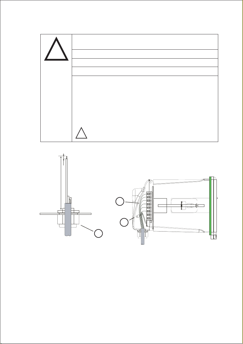
This instrument has a protection level of IP65. Please use waterproof cable
glands when you connect the line. Also, please loose it when you open the
cover. After connecting the line, please tighten the cable conductor
according to the above table 3 with attached tie line, or it will cause danger
because cable conductor or interface falls off when open the cover.
!
7 mm
90 mm
Please make sure to cut the power when you open the cover to
carry through any operation.
2
3
1
1. Waterproof cable glands
2. Cable (recommended stripping lengths for cables at least 90mm, please use 0.5 to 1 square
meter’s wire)
3. Cable ties
2
Page 8

2 PRODUCT DESCRIPTION
2.1 DESCRIPTION OF INSTRUMENT SPECIALITY
CON transmitters are used to measure conductivity and temperature value.
Transmitters can be used as monitor in water treatment, in process of chemical industry, in food
process, in cleaning water or wastewater treatment and in neutralization process.
This transmitter has many user-friendly and safety features which include:
Menu-driven program that simplifies set-up.
Built-in memory backup to ensure that set-up parameter and calibration information are not
erased if power off or power off in abnormal condition.
Long-life micro-switch key
IP65 all-day water and air proofing can be used in any adverse circumstances.
Adjustment of electrode offset value
Automatic temperature compensation mode, manual set-up of process temperature and
calibration temperature.
Separately adjustable high and low set point hysteresis (dead bands) prevents oscillating of
relays around the set points.
Large dual display LCD for easy reading with clear multiple annunciators, alarm status and
operational message annunciators
Back-light LCD can be also used in dark industrial situation.
Two switch on/off relays and one alarm relay
Independent alarm relay can be set up as calibration remind or clean relay, which can move with
control relay under alarm mode.
Anti-interference of electromagnetism—electric isolation of 0/4-20mA output, ensure the safety
of data collection and control effect.
RS-485 output
3
Page 9

2.2 MEASUREMENT AND CONTROL SYSTEM
Typical measurement system includes:
Conductivity on-line transmitter
United or separated temperature sensing instrument PT1000 of con compound electrode
Suitable con measurement electric cable
Immersion, flow or processing parts
Terminating controlling parts
0/4~20mA can connect with recording instrument
RS-485 can be used as multi-instrument communication
RL3 relay can be used as alarm or washing function
4
Page 10
2.3 APPEARANCE
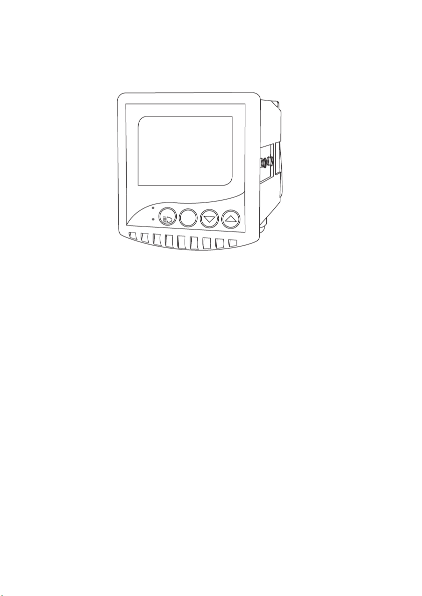
CDCN-961 CON/TDS/RES controller / transmitter
SP1
ENT
MOD
SP2
ESC
5
Page 11

2.3.1 INTRODUCTION OF DISPLAY
Two liquid crystal regions show measured value and indication and parameters of various status.
HOLD
ERR
MEA
SP1
CAL
SP2
mA
SET
ATC
Mode Indications:
- MEA:measurement mode
- SET :set-up mode
mS
- CAL :calibration mode
Status Indications:
C
- HOLD:relay actions and electric current output
are hold.
- ATC :automatic temperature compensation
indication, manual temperature compensation is
not displayed.
- ERR:error or warning indication
6
Page 12
2.3.2 KEY INSTRUCTION
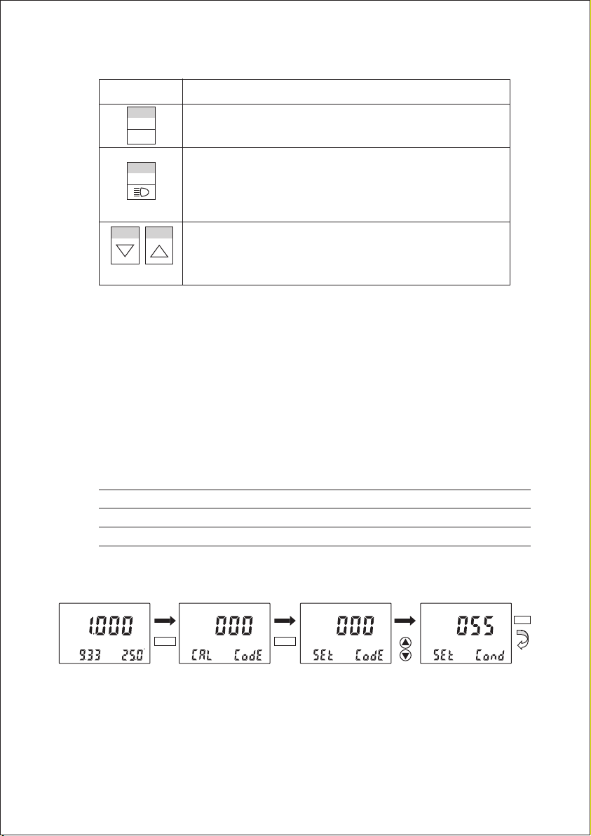
KEY Description
2
MOD
● Mode switch key or quit key
ESC
● Confirm key
1
ENT
● Entering sub-function form of function group in setting mode
● Confirm setting parameter and value
● Starting calibrating in calibration mode
● Back light on and off switch in measurement mode
3 4
● Choose function group to set-up parameters and value(If hold on
pressing, value changing will be quicker.)
● Press these two at the same time under measuring mode,
electrode constant and measuring range will be showed.
2.3.3 LED INDUCTION
Relay Induction
SP1 \ SP2 LED shows relevant working status of relays.
SP1 \ SP2 LED light-on shows that relays are under working status.
2.3.4 PASSWORD
When entering calibration mode and setting mode, there are passwords. Passwords are set by
factory and users cannot modify them by themselves. Followings are those passwords:
Password Mode / Instruction
020
028
055
2.3.5 PREVIEW OF FUNCTION
MEA
HOLD
mS
SP1
SP2
mA
MOD MOD
ATC
C
SET
System set-up mode
Calibration Mode
Action set-up mode
SET
HOLD
SET
HOLD
ENT
7
Page 13
SET
HOLD
SET
HOLD
SET
HOLD
SET
HOLD
SET
HOLD
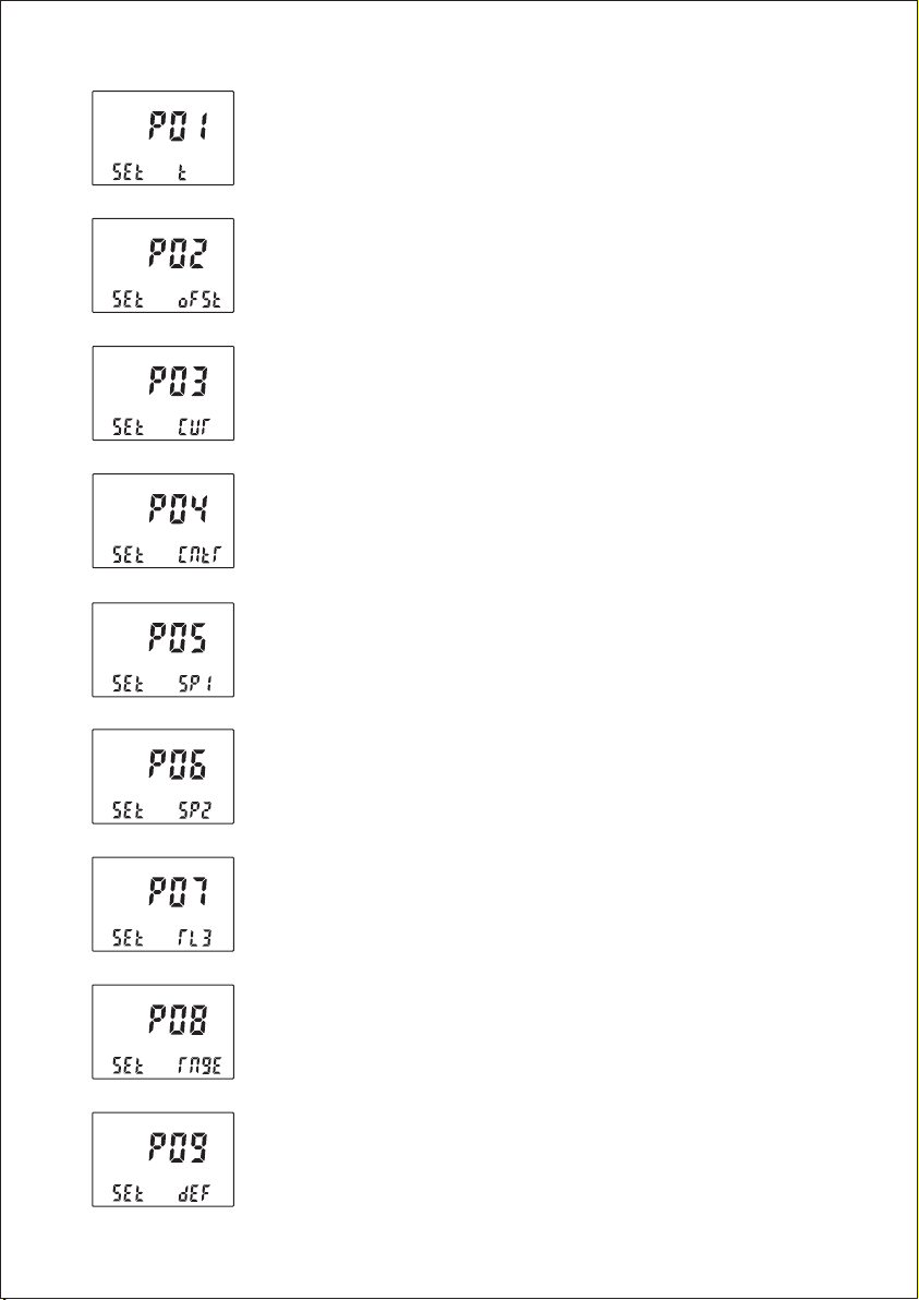
Temperature set-up sub-function: can modify relevant parameters such as auto or
manual temperature compensation, set-up of manual temperature compensation.
Offset set-up sub-function: can modify measuring value and cable resistance.
Electric current set-up sub-function: can set up output electric current.
Control mode set-up sub-function: can set up working mode of relays, can set up
limit control and ratio impulse control mode.
SP1 set-up sub-function:can set up action of relay 1, carry out auto control.
SET
HOLD
SET
HOLD
SET
HOLD
SET
HOLD
SP2 set-up sub-function:can set up action of relay 2, carry out auto control.
Relay 3 set-up sub-function: can set up action of relay 3, carry out functions of
cleaning, reminding of calibration and alarm.
Measurement range set-up sub-function: can set up Conductivity and TDS
measuring range.
Reverting to factory default setting sub-function: this function can revert all setting
values and calibration values to factory default setting.
8
Page 14
3 INSTALLATION AND ACCESSORY
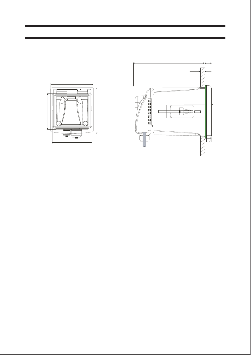
INSTALLATION
93. 5(3. 68)
100 (3.9 3)
93. 5(3. 68)
108 (4.2 5)
Panel cutout : 93.5*93.5mm (inch)
(panel installation)
136 (5.3 5)
12( 0.47 )
1-7 (0.0 3-0 .27
9
Page 15
CDCN-961 CONNECTION DIAGRAM
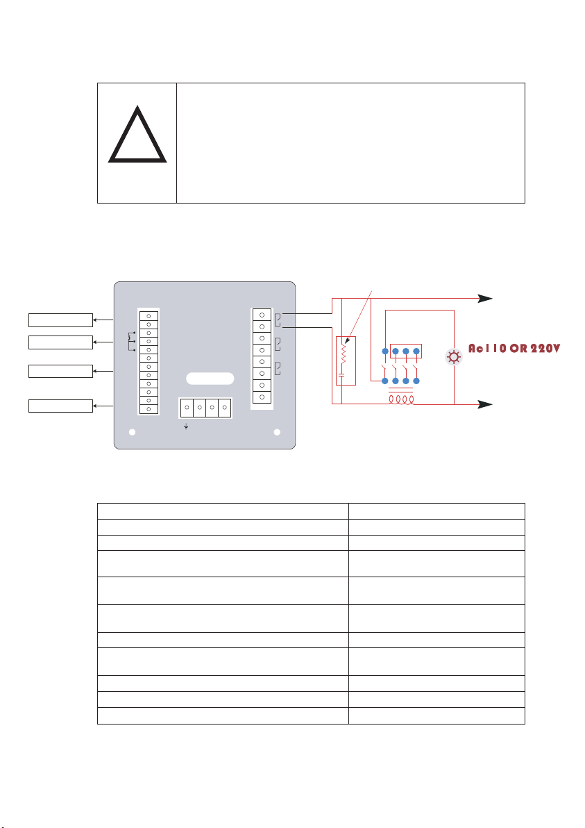
Warning: Make sure to power off before connecting. The back panel
consists of three connectors.
!
CDCN-961 connection diagram
RC circle
RS 485
TEMP input
Con sensor
4 ~ 2 0 m A
110V
220V
17
SP1
18
19
SP2
20
21
RL3
22
!
1000
PT
485A
485B
SEN1
SEN2
COM
mA +
mA -
DR1
DR2
01
02
03
04
05
06
07
08
S/N
09
10
11
12
13 14 15 16
~ ~ ~
N
WARNING
1. 485A output A
2. 485B output B
3. Temperature electrode input terminal (PT1000) red
4. Temperature electrode input terminal (PT1000) blue
5. CABL compensation terminal, use short circuit
between 4
6. Con drive 1 (2-wire system, use short circuit
between 6 and 7) yellow
7. Con sense 1
8. Con drive 2 (2-wire system, use short circuit
between 8 and 9) green
9. Con sense 2
10. COM
11. 4~20mA+
R
C
LED
RELAY
12. 4~20mA-
13. Earth wire
14. Input of alternating current
15. Electric source input 110V
alternating current (no 220V)
16. Electric source input 220V
alternating current (no 110V)
17. Relay A (SP1)
18. Relay A (SP1)
19. Relay B (SP2)
20. Relay B (SP2)
21. Clearing Relay (RL3)
22. Clearing Relay (RL3)
10
Page 16

NOTE: CDCN-961 can use 2 cell electrode and 4 cell electrode. Please note the type of electrode
and connecting way in the process of connecting electrodes. When use 2 cell electrode,
please connect 6 and 8, use short circuit between 6 and 7, also 8 and 9. When use 4 cell
electrode, please connect with relevant pins.
Notice: Relay contactor volume of our instrument is 220 VAC/0.5A. Please do not connect with
bigger appliance. Please install bridge relay to transit according the above diagram, or bear
the responsibility by them. There is RC parameter, which is 100 ohm/0.22uF on the relay
contactor. Please pay attention to that.
11
Page 17
MEASUREMENT MODE
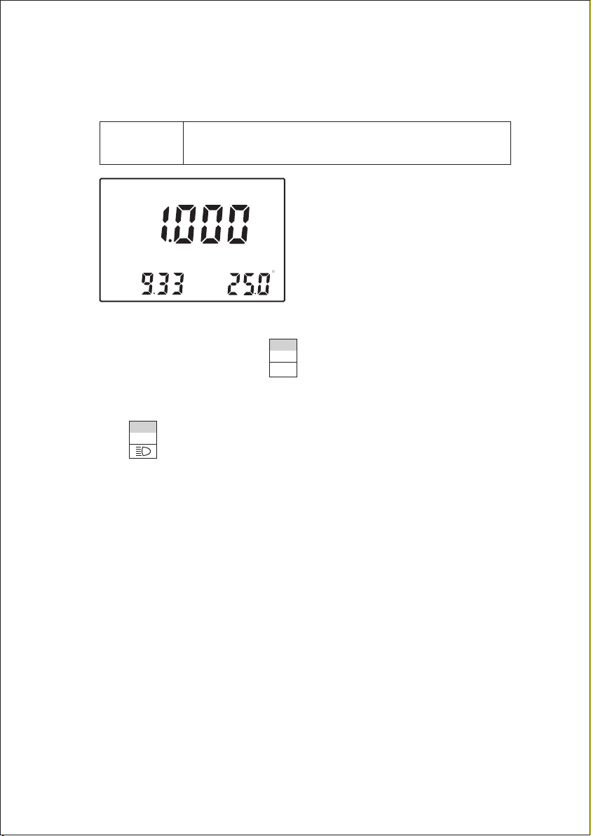
When the controller is initially powered on, it automatically enters into the Measurement mode after
the large dual LCD displays all segments briefly.
Please notice: in order to get exact measurement information, users
should calibrate measurement system (transmitter and electrode).
SET
CAL
MEA
HOLD
ERR
SP1
SP2
ATC
mA
Such annunciators or icons, as mS, at the upper right side of the display show the current different
measurement mode of transmitters.
In measurement mode, you can press key once or twice to enter into the function form of
calibration or set password input.
Then input relevant password to enter into calibration mode or set up mode. Please refer to Item
4(Calibration Mode) or Item 5 (set up mode).
1
ENT
Press key under measurement mode, you can open or close back light of LCD.
MEA at the top of the LCD shows that the instrument
is under the status of measuring.
The upper display shows CON value, while the lower
mS
display shows temperature value under Con
measurement mode.
Annunciator at the left lower side of the display show
the value of transmitting output electric circuit, which
C
as the way that users calibrate the output electric
circuit.
2
MOD
ESC
12
Page 18
4 CALIBRATION MODE
2
MOD
mS
C
MOD
2
MOD
ESC
ESC
SET SET SET
HOLD
MOD
2
NOTE: Anytime press to quit calibration mode and return to upper
function. If return to measurement mode, old calibration information
will be kept and used. After returning to measurement mode,
password will automatically set up from 28 to 000 when entering
calibration mode.
MOD
ESC
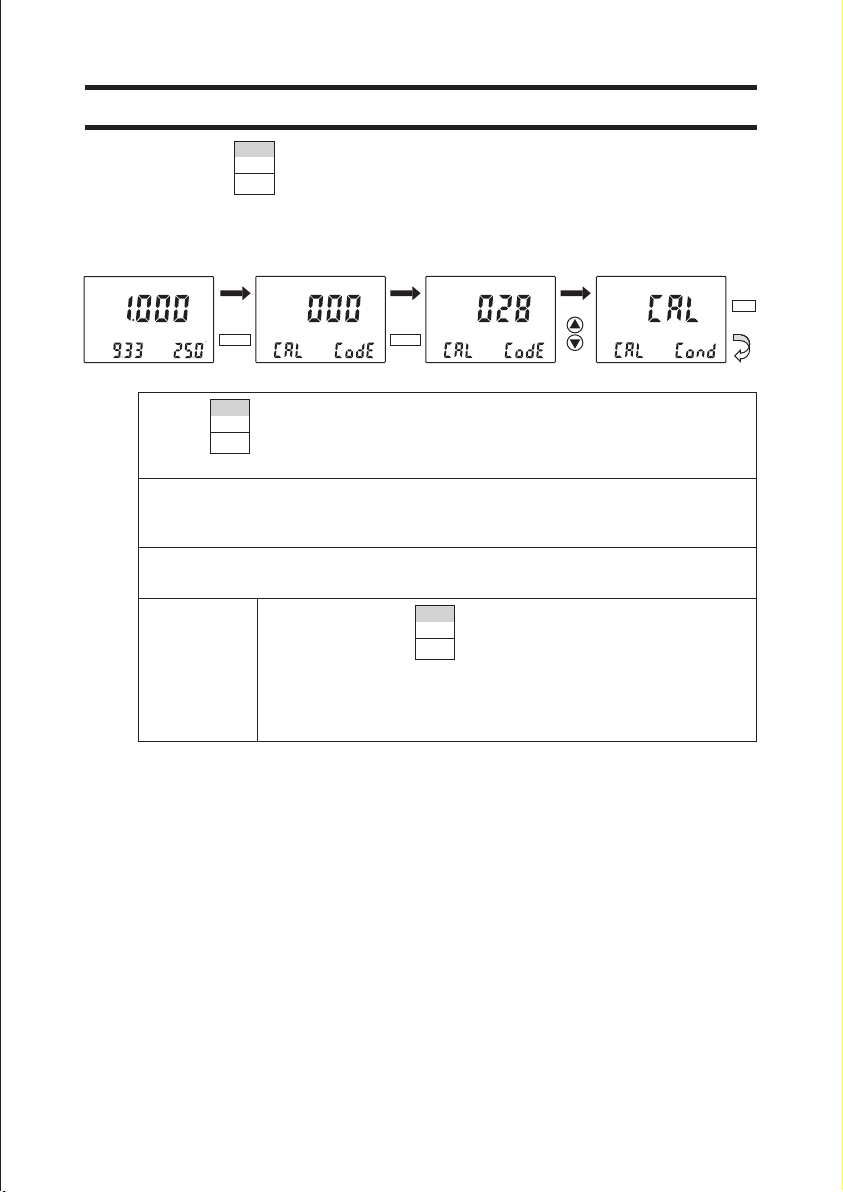
You can press once under measurement mode and then input password 028 to get access
to calibration mode. Please operate according to following squares.
4.1 ENTERING CALIBRATION MODE
SET
CAL
MEA
SP1
SP2
ATC
mA
1. Press twice in measurement mode and enter into form for password input of
calibration mode.
2. After entering function form of calibration password input, LCD will ask you to input
password. Press ▲ or▼ to input calibration password 28, then press ENTER to confirm
the password.
3. Press ENTER to enter into calibration sub function form, lower display will show CAL cond.
If you want to calibrate, please refer to relevant items.(please refer to upper pictures).
ENT
13
Page 19
4.2 CALIBRATION OF CONDUCTIVITY
2
MOD
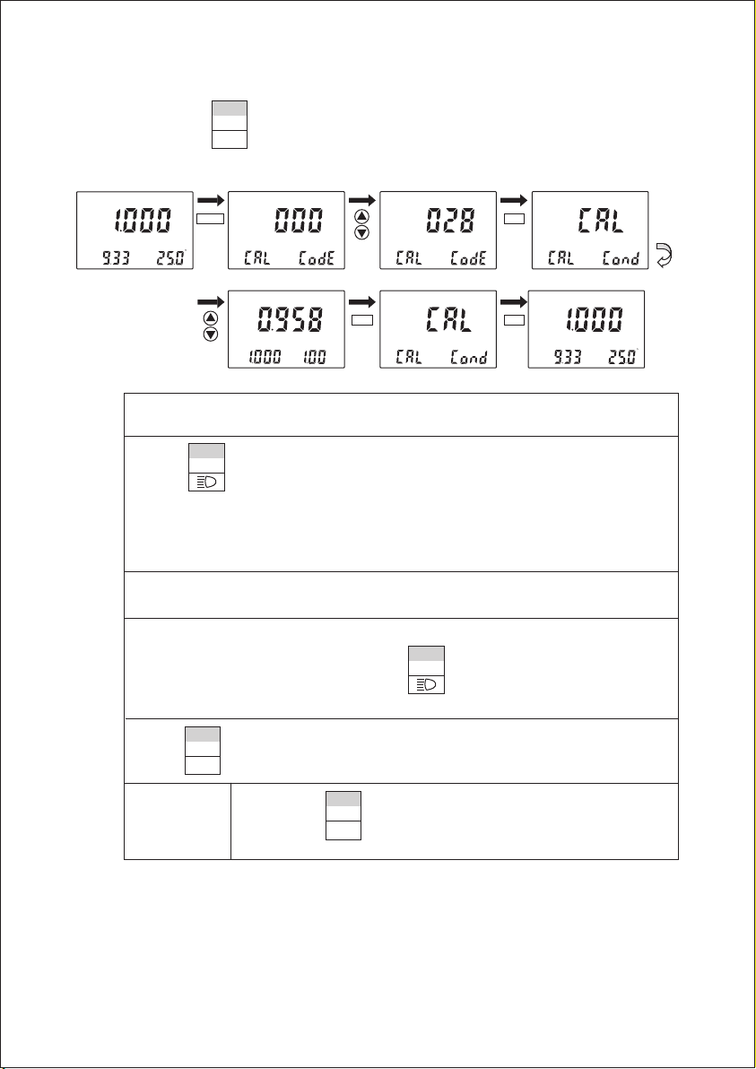
You can press once under measurement mode and then input password 028 to get access
to calibration mode. Please operate according to following squares.
ESC
SET
CAL
MEA
MOD
mS
SP1
SP2
ATC
mA
C
1. Entering calibration mode as Item 4.1 described. LCD will show CAL cond (Con Calibration
mode).
1
ENT
2. Press key to enter into calibration, LCD will show electrode constant and show
menu. The lower display will show 1.000 K=1.00,this function form shows the electrode
constant of last calibration. The upper display will show CAL and the main display zone
will show conductivity measuring value. Users can press ▲or▼ key to select electrode
constant to calibrate, also, users can use standard solution to select the value to calibrate.
3. Put electrode into the prepared standard solution. You should put temperature electrode
into the same solution under the automatic temperature compensation mode.
4. Press ▲ or ▼ key to select electrode constant to calibrate, also, users can use standard
solution to select the value to calibrate. Press to confirm when finished, and return
to calibration remind mode.
SET SET SET
ENT
HOLD
CAL
mS
ENT
k
=
CAL
HOLD
1
ENT
ESC
MEA
SP1
SP2
SET
CAL
mS
ATC
mA
C
done
2
MOD
ESC
5.Press once to return to calibration mode and finish the calibration process.
2
NOTE: Press key to quit set up mode at any time. Instrument will
return to measurement mode automatically.
MOD
ESC
14
Page 20
NOTE: Transmitter will show ERR when calibration is error. Under this situation,
2
MOD
!
press to quit and calibrate again from step 1. It will show ERR
again under following situations:
(1) Use wrong standard solution or standard solution is expired.
(2) Electrode is aging, constant is over permitting range.
(3) Electrode wire is broken or leakage because of joint corrosion.
NOTE: When calibrating under manual temperature compensation, transmitter
will automatically switch to calibration temperature from pre-set
measurement temperature. When leaving calibration mode, transmitter
will switch to measurement temperature again. (Please refer to Item 5.2
for setting measurement temperature and calibration temperature)
NOTE: ELE K=1.00 presents the standard constant of electrode is 1.0, the left
1.000 present the actual constant of electrode.
ESC
4.3 SYSTEM SET UP
2
MOD
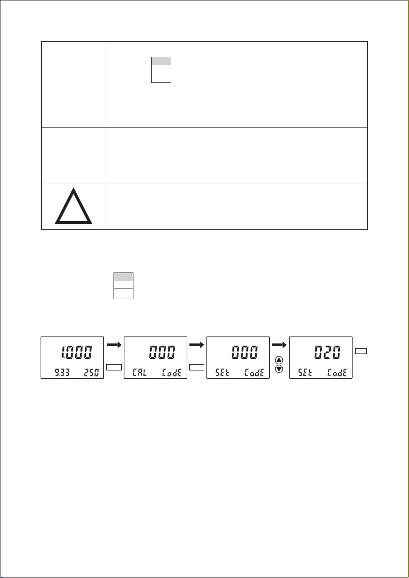
You can press twice under measurement mode and then input password 020 to get access
to System set-up mode. Please operate according to following squares.
ESC
Entering System set-up mode
SET
CAL
MEA
HOLD
mS
SP1
SP2
ATC
MOD
mA
C
SET
HOLD
MOD
SET
HOLD
SET
ENT
15
Page 21
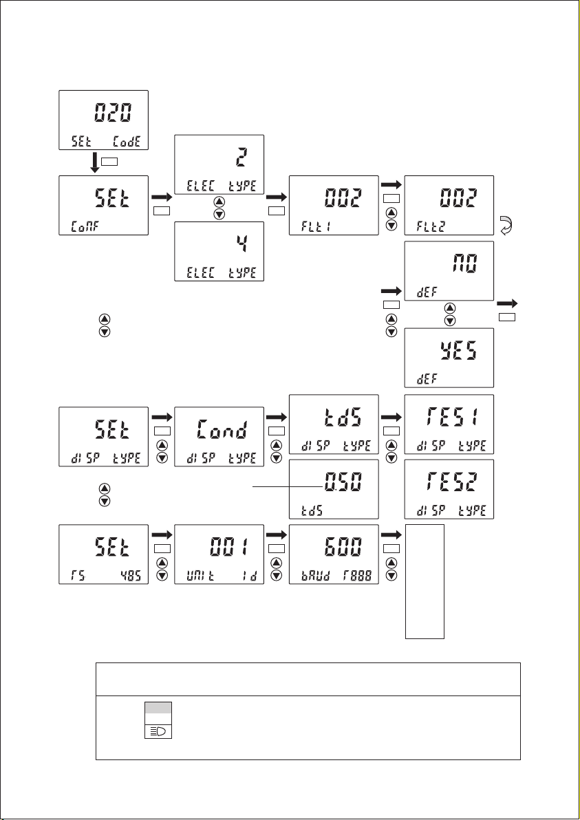
Entering system mode according to following diagram :
SET
HOLD
SET
ENT
SET
HOLD
HOLD
SET
HOLD
ENT ENT
SET
HOLD
ENT
SET
HOLD
SET
HOLD
ENT
ENT
SET
HOLD
SET
HOLD
SET
HOLD
HOLD
ENT ENT ENT
HOLD
ENT ENT ENT
SET
0.40 ~ 1.00
SET
HOLD
HOLD
HOLD
SET
HOLD
SET
HOLD
SET
300
600
SET
SET
900
1200
2400
4800
9600
19200
1. Entering system set-up mode as Item 4.3 described. LCD display CONF(configuration
sub-function).
1
ENT
2. Press to enter, LCD show to choose conductivity electrode. Lower of LCD will show
ELEC TYPE,upper will show 2(2 way electrode). Users can press ▲ or ▼ to choose 4 (4
16
Page 22
1
ENT
way electrode). Press to enter into number filtering set up menu. Press ▲ or ▼ to modify
number filtering value. Press ENT to confirm and enter into reverting to factory setting menu.
3. Under measurement mode, users can choose measurement mode of conductivity, TDS, resistance.
The upper LCD will show SET, the lower LCD will show DISP TYPE. Press ENT to enter or press
▲ or ▼ to choose relevant measurement mode, press ENT to confirm. Under TDS measurement
mode, users can set up the transit parameter of TDS from 0.40 to 1.00. The relationship between
TDS and conductivity is: CON * TDS parameter = TDS. Two measurement range, RES1 and RES2,
can be chosen among resistance. RES1 is correspondent to 3.0M~300.0M,RES2 is
correspondent to 0.3M~30.0M.
1
ENT
4. RS-485 set up menu,upper LCD shows SET,lower LCD shows RS-485,press to enter
instrument remind ID number. Press ▲ or ▼ to input number, press ENT to confirm and enter into
baud rate set up menu. Press ▲ or ▼ to choose relevant value, press ENT to confirm.
17
Page 23
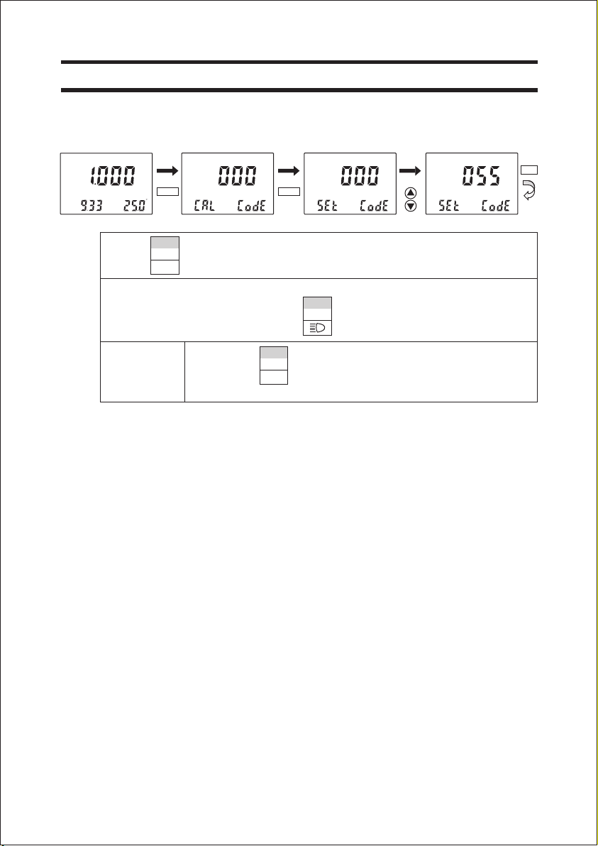
5 SET UP MODE
ENTERING SET UP MODE
In set up mode, transmitter can be set up according to your need.
SET
CAL
MEA
HOLD
mS
SP1
SP2
mA
1. Press twice in measurement mode.
2. LCD ask you to input password. Use ▲ or ▼ to input the password.
– Input 055 to change parameter. Press to confirm.
MOD MOD
ATC
C
2
MOD
ESC
SET
2
NOTE: Press twice to quit set up mode at anytime.
Instrument will return to measurement mode automatically.
MOD
ESC
HOLD
1
ENT
SET
HOLD
SET
ENT
18
Page 24
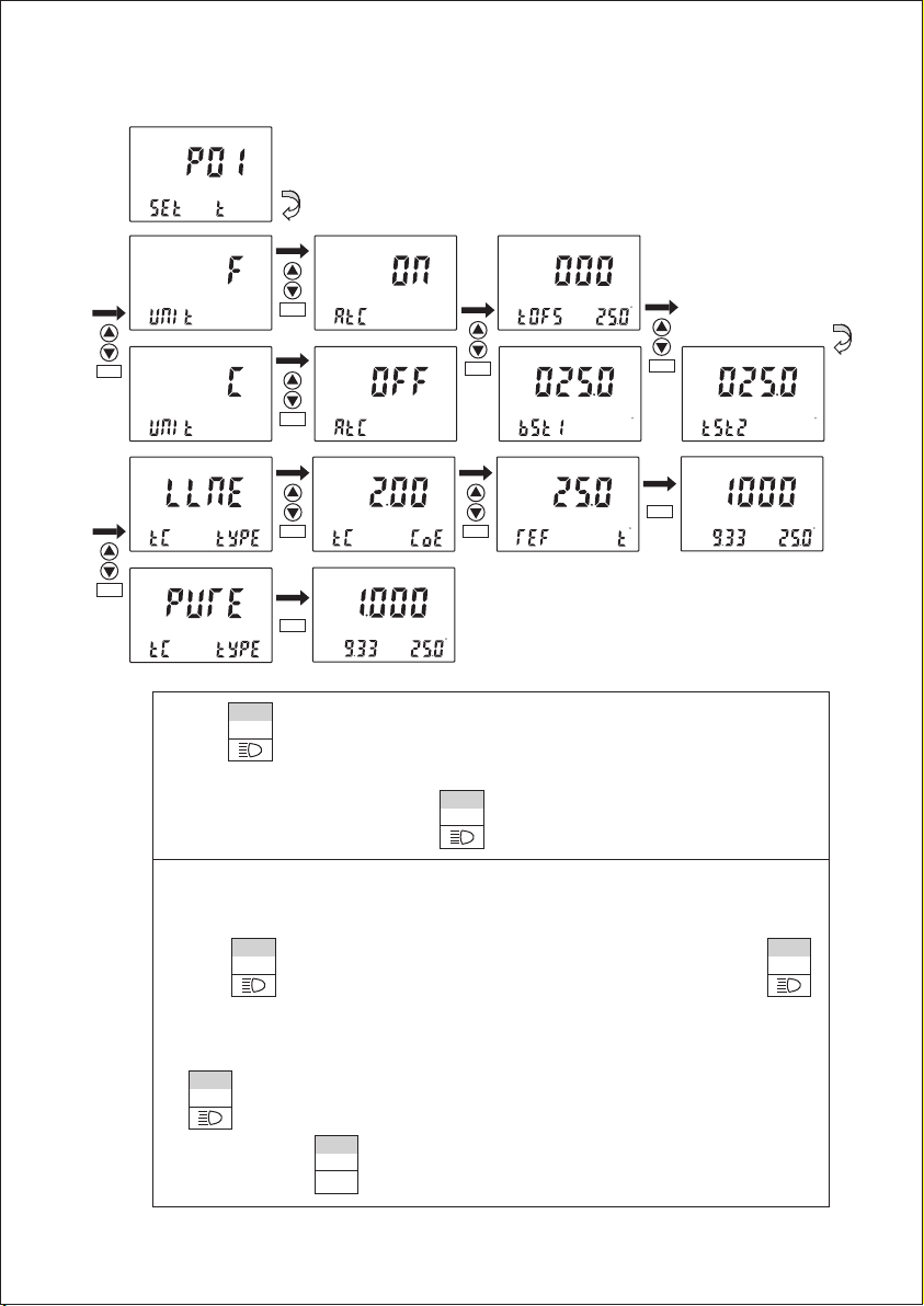
5.1 P01:TEMPERATURE SET-UP SUB-FUNCTION
SET
HOLD
ENT
ENT
SET
HOLD
SET
HOLD
SET
HOLD
SET
HOLD
1
ENT
HOLD
ENT
HOLD
ENT
HOLD
ENT
ESC
SET
HOLD
SET
SET
MEA
SP1
SP2
mA
ENT
HOLD
HOLD
%
ENT
mS
ATC
C
done
SET
C
SET
SET
ENT
HOLD
C
ESC
C
1. Press to enter from P01 screen. LCD main display zone show C, which means
temperature unit is centigrade. Press can press ▲ or ▼ to switch to F,which means
1
ENT
temperature unit is Fahrenheit. Press to confirm and enter into next item.
SET
C
MEA
mS
SP1
SP2
ATC
C
mA
done
2. LCD main display zone shows ON, which means automatic temperature compensation
function is open. User can press ▲ or ▼ to switch to OFF and close automatic
temperature compensation function to use manual temperature compensation instead.
1
ENT
Press to confirm item. If users choose auto temperature compensation, press
, instrument enters into modifying status of temperature measurement value. LCD main
display zone show current measurement value of temperature. The lower display TOFS
tell users that they can use ▲ or ▼ to modify current temperature display value. Press
1
ENT
to confirm and return to P01 Sub-function form. Use ▲ or ▼ to select other sub
2
MOD
functions or press to return to measurement status.
ESC
1
ENT
19
Page 25
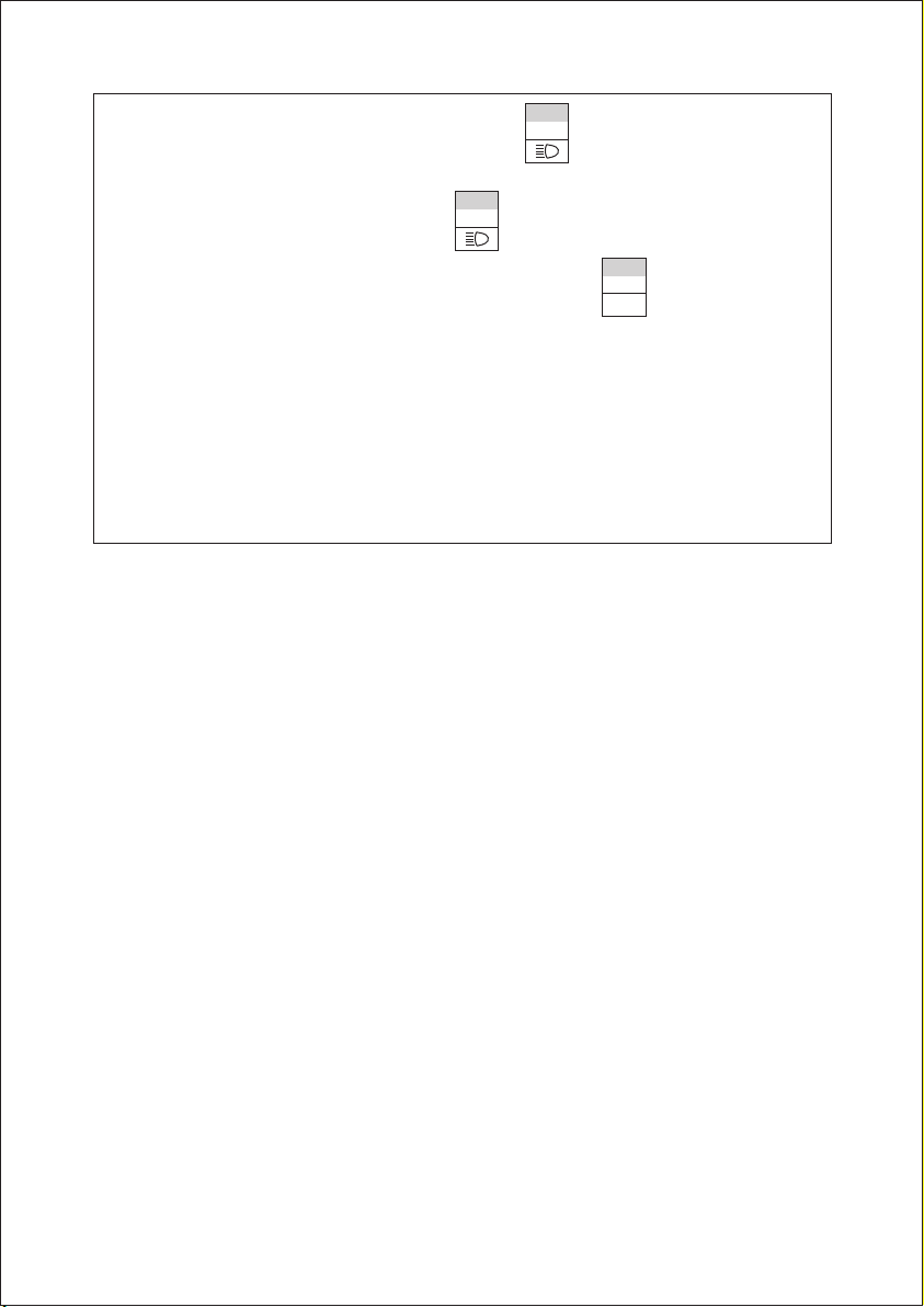
1
ENT
3. In the status of manual temperature compensation, press and instrument enter set up
status of manual temperature compensation user can use ▲ or ▼ to set up process temperature
1
TST1 and calibration temperature TST2. Press to confirm and return to P01 Sub-function
form or press ▲ or ▼ to select other sub functions to set up or press to return to
measurement status. TST1 is the compensation temperature under normal measurement while
TST2 is the compensation temperature under calibration. Since temperatures are not the same
in calibration and normal measurement when instrument is used, two set up values under manual
temperature compensation status are convenient. Users will not set manual temperature
compensation value back and forth. For example, if user’s process temperature is 50.0℃ and the
temperature of standard solution when calibrating is 10.0℃, use can set TST1 as 50.0℃ and set
TST2 as 10.0℃ for afterwards convenient use. Press ENT to confirm and enter into set-up of
temperature compensation parameter. LCD shows LINE (linear compensation), use ▲ or ▼ to
switch to PURE (pure water compensation). Choose LINE to set up temperature compensation
parameter and basic temperature.
ENT
2
MOD
ESC
20
Page 26
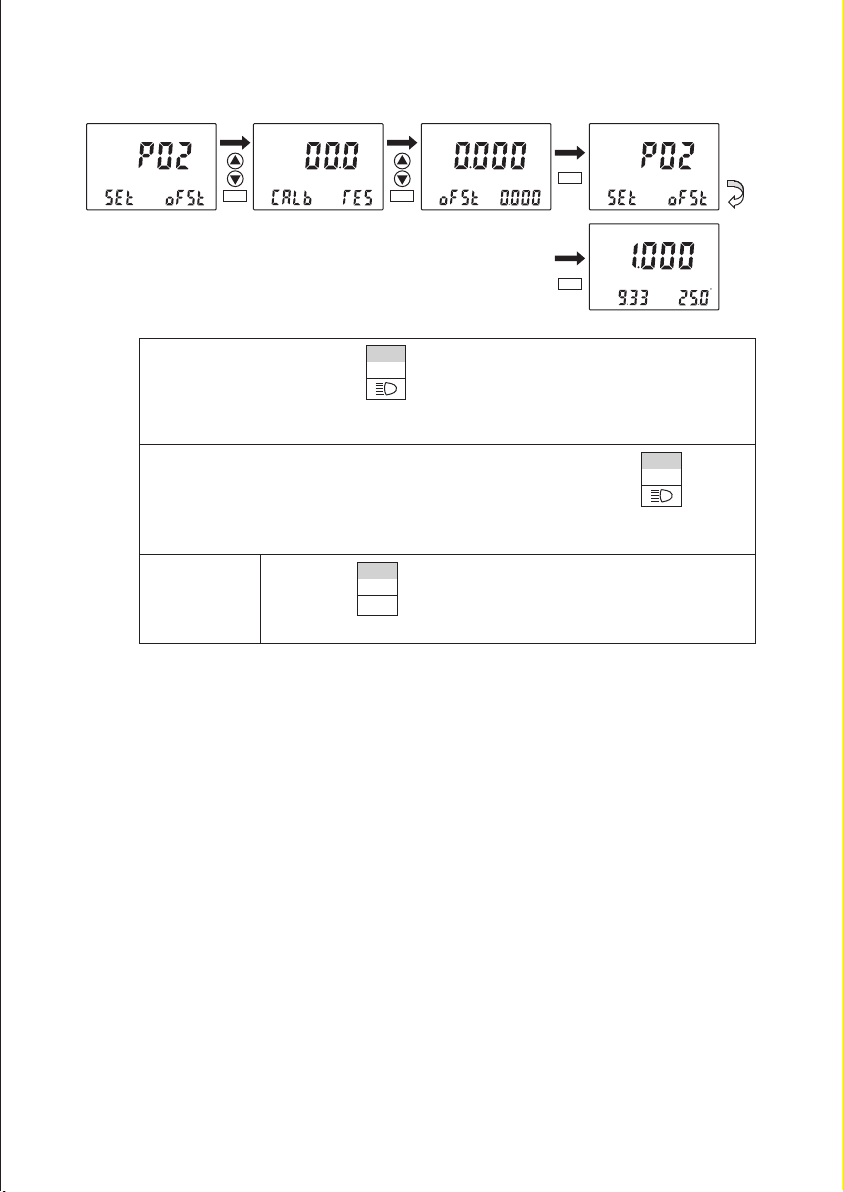
5.2 P02:OFFSET SET-UP SUB-FUNCTION
SET
HOLD
HOLD
ENT ENT
SET
HOLD
1
ENT
SET
mS
ENT
ESC
1. In P02 sub-function form, press . LCD shows CABL RES, users can set up
resistance of cable to compensate indication. Compensation of CABL RES is only valid
between 0.0 to 300.0mS. Press ENT to confirm and enter into offset set-up.
2. User can press ▲ or ▲ to adjust offset to modify measurement value. Press to
confirm and return to P02 sub-function form or press ▲ or ▲ to select other sub-function
to set up.
2
MOD
ESC
Note: Press to quit set-up mode at anytime.
Instrument will return to measurement mode automatically.
SET
HOLD
MEA
mS
SP1
SP2
ATC
mA
ENT
C
done
1
21
Page 27
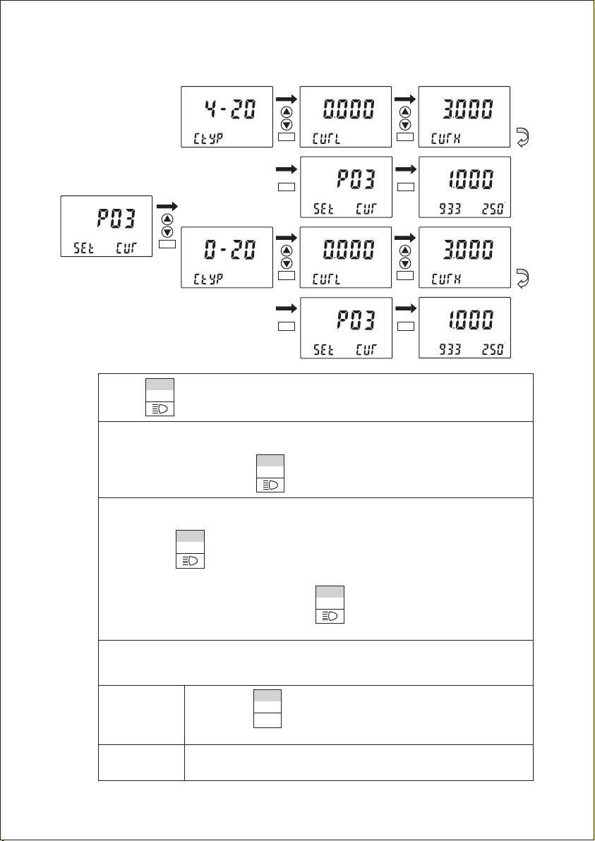
5.3 P03: OUTPUT CURRENT SUB-FUNCTION
SET
HOLD
HOLD
SET
SET
HOLD
mS
mS
mA
SET
HOLD
ENT
1
ENT
SET
HOLD
mA
ENT
SET
HOLD
ENT ESC
SET
HOLD
ENT
SET
HOLD
ENT ESC
ENT
MEA
mS
SP1
SP2
ATC
C
mA
SET
HOLD
mS
ENT
MEA
SP1
SP2
mA
done
mS
mS
ATC
C
done
1. Press to confirm in P03 sub-function. Entering set up of the sub-function.
2. The lower display shows CTYP. The upper display shows 4-20 (it means electric circuit
output from 4 mA to 20 mA). User can press ▲ or ▼ select 0-20 (it means electric circuit
1
ENT
output from 0 to 20 mA). Press to confirm and enter into set-up of transmitting range.
3. The lower display shows CURL while the upper display shows 0.00, which means that
0.00 mA transmitting range indicates 0.00 ms. User can press ▲ or ▼ to adjust the actual
1
ENT
value. Press to confirm. The lower display shows CURH while the upper display
shows 30.00, which means 20.00mA transmitting range indicates 10.00 ms. User can press
1
ENT
▲ or ▼ key to adjust the actual value. Press to confirm and return to P03
sub-function firm or press ▲ or ▼ to select other sub-functions and to set up.
For example, set CTYP to 0 or 4, set CURL to 2.00 and set CURH to 10.00, which means
0 / 4 to 20 mA output mode is selected as circuit output. 0 / 4.00 mA indicates 2.00 ms,
20.00 mA indicates 10.00 ms
2
MOD
ESC
Note: Press to quit set-up mode at anytime.
Instrument will return to measurement mode automatically.
Note: This parameter allows you to set range of circuit output, but
transmitting high point and low point can’t be overlapped.
22
Page 28
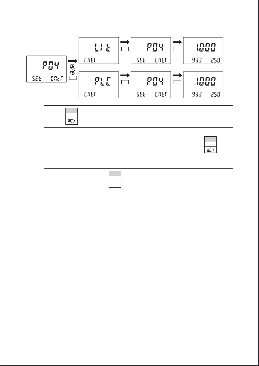
5.4 P04:CONTROL MODE SUB-FUNCTION
HOLD
SET
HOLD
SET
ENT
HOLD
1
ENT
SET
HOLD
ENT ESC
HOLD
ENT ESC
1. Press in P04 sub-function form to enter into concrete set up procedure.
2. The lower display shows CNTR while the upper display shows LIT. This form allows users
set up limited control mode. User can press ▲ or ▲ to select PLC mode. Press to
confirm and return to P04 sub-function form. Use ▲ or ▲ to select other sub-functions
and to set up.
2
MOD
ESC
Note: Press to quit set up mode at any time.
Instrument will return to measurement mode automatically.
SET
SET
MEA
mS
SP1
SP2
ATC
C
mA
MEA
SP1
SP2
mA
ENT
done
mS
ATC
C
done
1
23
Page 29
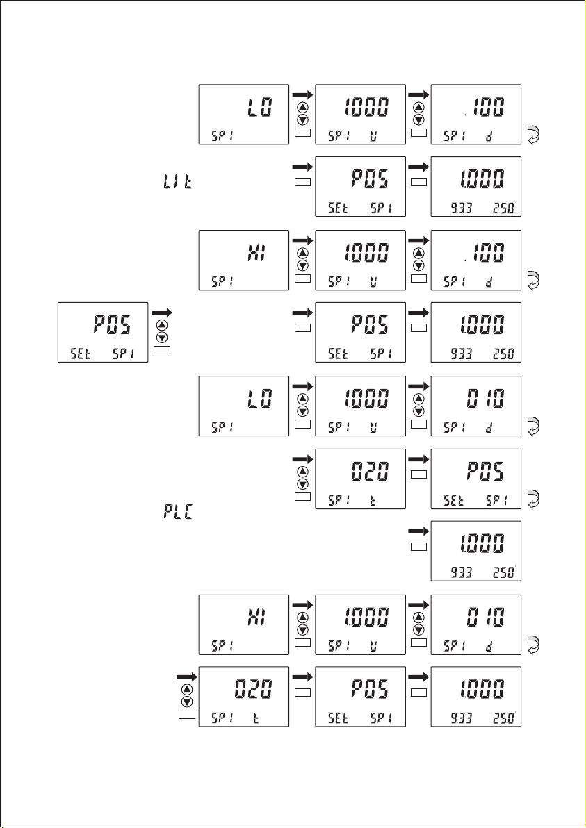
5.5 P05:RELAY 1 SET-UP SUB-FUNCTION
SET
HOLD
HOLD
SET
HOLD
mS
SET
mS
ENT
SET
HOLD
HOLD
ENT ESC
HOLD
SET
SET
ENT
MEA
mS
SP1
SP2
ATC
C
mA
SET
HOLD
mS
done
mS
ENT ENT
SET
HOLD
HOLD
ENT ESC
ENT
SET
HOLD
HOLD
SET
SET
mS
MEA
mS
SP1
SP2
ATC
C
mA
SET
HOLD
done
ENTENT
SET
MEA
mS
SP1
SP2
ATC
C
mA
done
ENT
SET
HOLD
ENT
HOLD
ESC
SET
HOLD
HOLD
SET
HOLD
mS
SET
ENT ENT
SET
MEA
mS
SP1
SP2
ATC
C
mA
done
ENT
SET
HOLD
HOLD
ENT ESC
24
Page 30
1
2
MOD
ESC
ENT
1
ENT
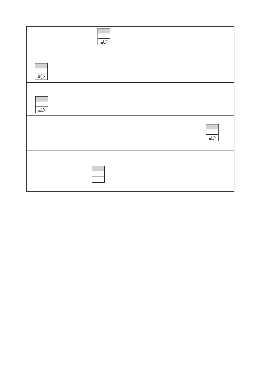
1. In P05 sub-function form. Press to enter into concrete set-up procedure.
2. The lower display shows SP1 while the upper display shows HI, which means set point 1 is under
high-point control status, relay begins to work when the measured value up to set value. Press
1
ENT
to confirm and enter into next set up procedure.
3. The lower display shows SP1 U while the upper display shows concrete value. User of the
function form can press ▲ or ▼ to adjust the value to confirm concrete set up value. Press
1
ENT
to confirm and enter into next set up procedure.
4. The lower display shows SP1 d,this function form sets hysteresis band under limited control mode
to protect relay, which may oscillate frequently around set point and be damaged. Press
to confirm and enter into next set up procedure.
Note: There are two modes of relay set-up: LIT and PLC. Please refer to next
page about PLC.
Note: Press to quit set up mode at any time.
Instrument will return to measurement mode automatically.
25
Page 31
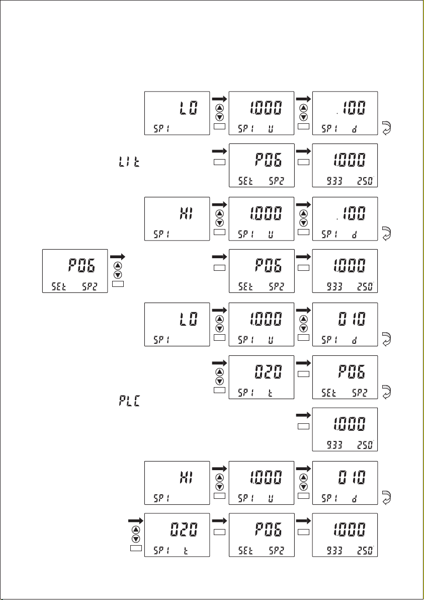
5.6 P06:RELAY 2 SET-UP SUB-FUNCTION
Working principle of this part is the same as which of P05 relay 1 set-up sub-function. Please
operate according to P05.
SET
HOLD
HOLD
ENT
SET
HOLD
HOLD
ENT ESC
HOLD
SET
HOLD
mS
ENT
SET
SET
HOLD
mS
SET
mS
MEA
mS
SP1
SP2
ATC
C
mA
SET
done
mS
ENT ENT
SET
HOLD
HOLD
ENT ESC
ENT
SET
HOLD
HOLD
SET
SET
mS
MEA
mS
SP1
SP2
ATC
C
mA
SET
HOLD
done
ENTENT
SET
MEA
mS
SP1
SP2
ATC
C
mA
done
ENT
SET
HOLD
ENT
HOLD
ESC
SET
HOLD
HOLD
SET
HOLD
mS
SET
ENT ENT
SET
MEA
mS
SP1
SP2
ATC
C
mA
done
ENT
SET
HOLD
HOLD
ENT ESC
26
Page 32

NOTE:Set-up value range of hysteresis band under limited control mode is from 0.00 to 2.0 ms.
For example, if high point is 7.00 ms and hysteresis band is 0.50 ms, movement range of
the relay is from 6.50 ms to 7.00 ms. If low point is 6.00 ms and hysteresis band is 0.20 ms,
movement range of the relay is from 6.00ms to 6.20 ms.
NOTE:In PLC control mode, movements of the relay meet following formulas:
C * (VM – VS) * U * T / 14
C is discriminate parameter for high / low point.
It is +1 when set to high point and it is -1 when set to low point.
VM is measured value.
VS is set value.
U is control parameter, such as sp1 d or sp2 d
T is time constant (represent the whole movement circle of relay): SP1 t or SP2 t
27
Page 33
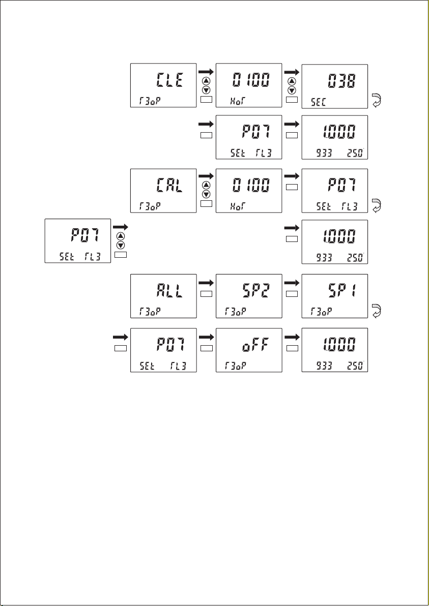
5.7 P07:ALARM RELAY 3 SET-UP SUB-FUNCTION
SET
HOLD
HOLD
ENT
SET SET
HOLD
HOLD
ENT ESC
HOLD
SET
HOLD
SET
ENT
SET
ENT
MEA
mS
SP1
SP2
ATC
mA
HOLD
C
done
SET
ENT
SET
HOLD
ENT
HOLD
HOLD
ENT
SET SET
HOLD
ENT ENT
SET
HOLD
ENT ESC
SET
ESC
MEA
mS
SP1
SP2
ATC
mA
HOLD
MEA
SP1
SP2
mA
C
done
SET
mS
ATC
C
done
28
Page 34
1
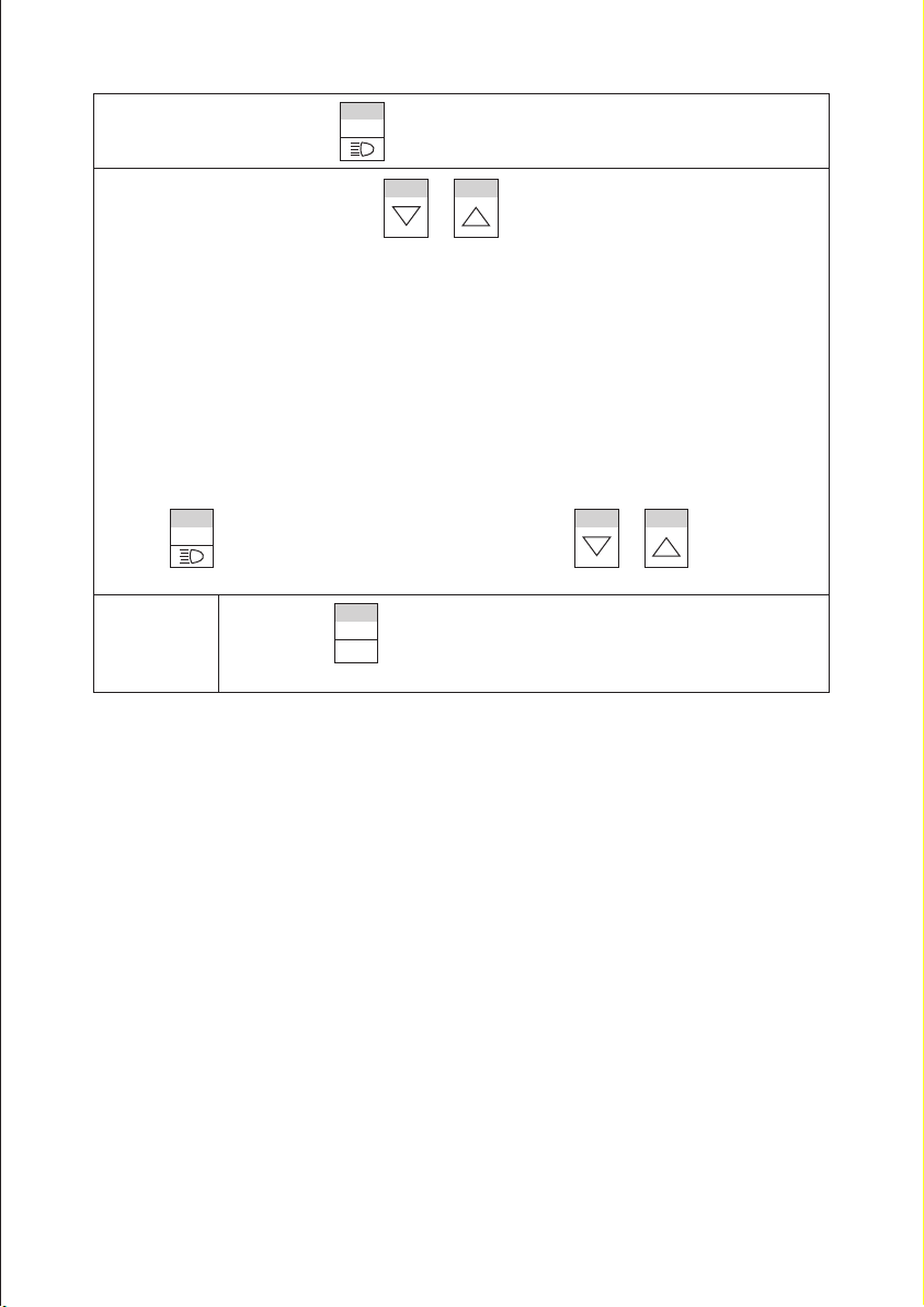
1. Select P07 sub function, Press to confirm. Enter into concrete set-up procedure.
2. Select concrete working mode. Press or to select suitable control mode.
- CAL=Relay 3 as calibrationg alarm relay
- ALL=move with two relays simultaneously
- SP1=relay 3 moves with SP1
- SP2=relay 3 moves with SP2
- OFF=relay 3 is off
Press ENTER to confirm your set up.
If user select CAL working mode, he can set calibration indicate intervals in the function form, use
houras the unit. In this way, instrument and electrode can keep their reliability.
If user select CLE working mode, he can set cleaning time intervals in the function form, use hour
as the unit; cleaning continuous time, use second as the unit. In this way, instrument and electrode
can keep their reliability. User can install cleaning equipment to increase service life and reliability
of electrode.
1
ENT
Press to confirm and return to P07 sub-function form. Use or to select other
sub-functions to set up.
NOTE: Press to quit set up mode at any time.
Instrument will return to measurement mode automatically.
ENT
2
MOD
ESC
3 4
3 4
29
Page 35
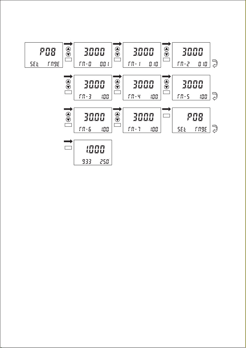
5.8 P08:MEASUREMENT RANGE CHOOSE SUB FUNCTION
SET
HOLD
HOLD
ENT
HOLD
ENT
HOLD
ENT
ESC
SET
uS
k
=
SET
uS
k
=
SET
k
=
MEA
SP1
SP2
ATC
mA
HOLD
ENT ENT
HOLD
ENT ENT
HOLD
mS
ENT
mS
C
done
SET
uS
k
=
SET
uS
k
=
SET
k
=
HOLD
HOLD
ENT
HOLD
mS
SET
uS
k
=
SET
mS
k
=
SET
30
Page 36
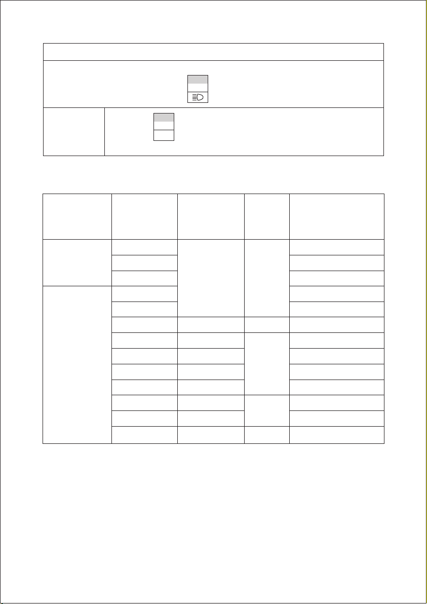
1. Press key to confirm in P08 and enter in concrete set-up procedures.
2. You can set up measurement range of conductivity and TDS in this sub-function. Use ▲ or ▼ to
1
ENT
select the measurement range and press to confirm.
2
MOD
Form of Measurement Range
Note: Press to quit set-up mode at any time.
Instrument will return to measurement mode automatically.
ESC
Type of
temperature
compensation
PURE
LINE
Measurement
Mode
RES1 3.0~300.0 M
RES2 0.3~30.0 M
CON/TDS 3.000 μS / ppm
RES1 3.0~300.0 M
RES2
CON/TDS 7 10.0 300.0 mS / ppt
Code of
measurement
range
X 0.01
6 30.00 mS / ppt
5 3.000 mS / ppt
4 300.0 μS / ppm
3
2 30.00 μS / ppm
1
0 0.01 3.000 μS / ppm
Constant
1.00
0.10
Measurement range
Ω
Ω
0.3~30.0 M
30.00 μS / ppm
3.000 μS / ppm
Ω
Ω
31
Page 37
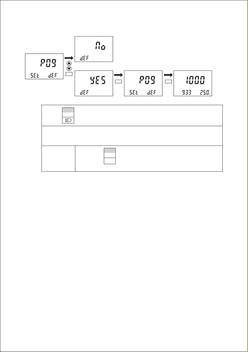
5.9 P09:TRANSMITTING RATE SUB FUNCTION
SET
HOLD
SET
HOLD
ENT
HOLD
1
1. Press in P09 to enter into concrete set-up procedures.
2. The lower display of the instrument shows DEF while the upper display shows NO (YES).
User can press ▲ or ▲ to select necessary items. If select YES, all settings will be reset
to factory default. User’s setting will be lost.
ENT
SET
HOLD
ENT ESC
2
MOD
Note: Press to quit set up mode at any time.
Instrument will return to measurement mode automatically.
ESC
SET
MEA
SP1
SP2
mA
mS
ATC
C
done
32
Page 38
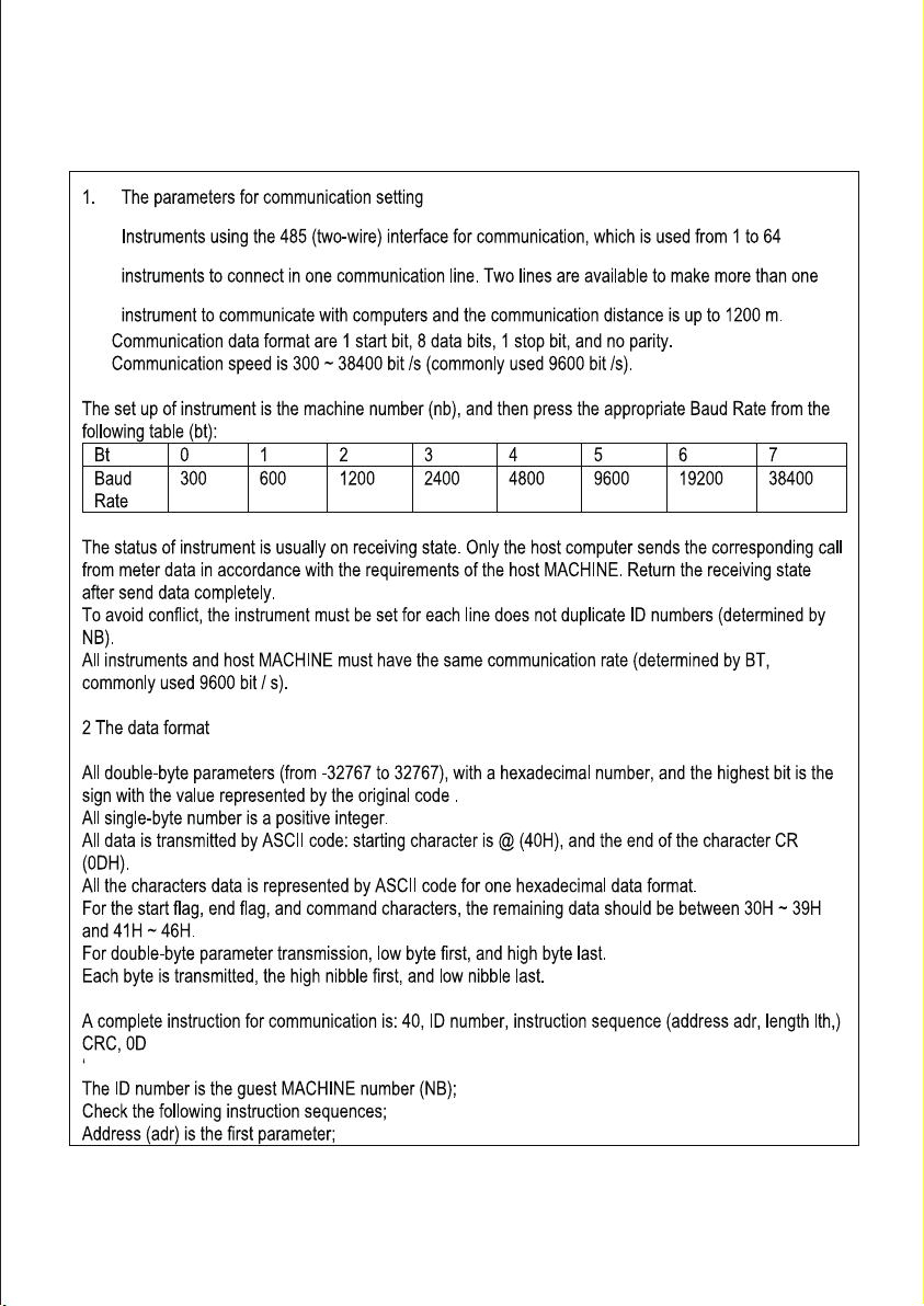
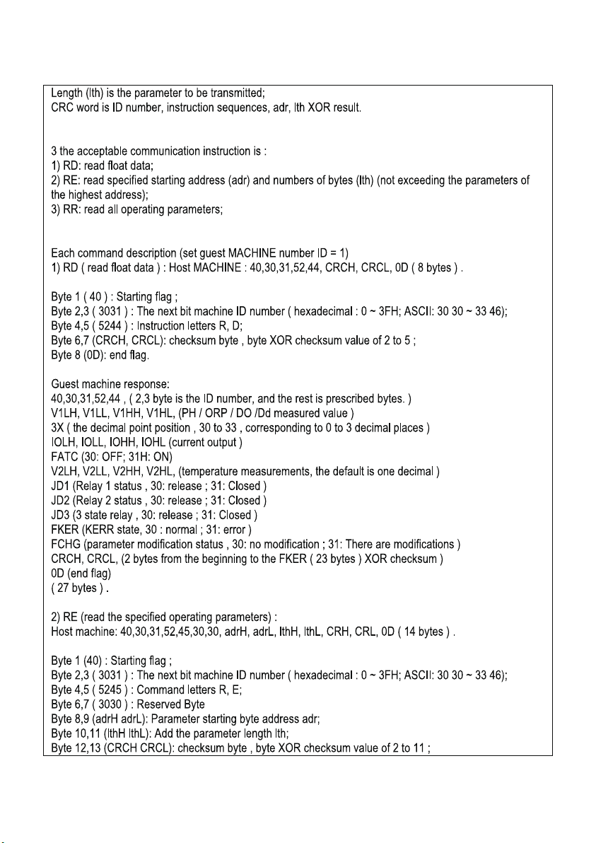
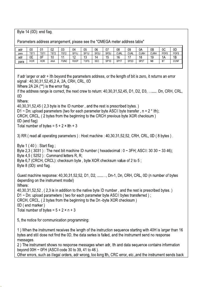
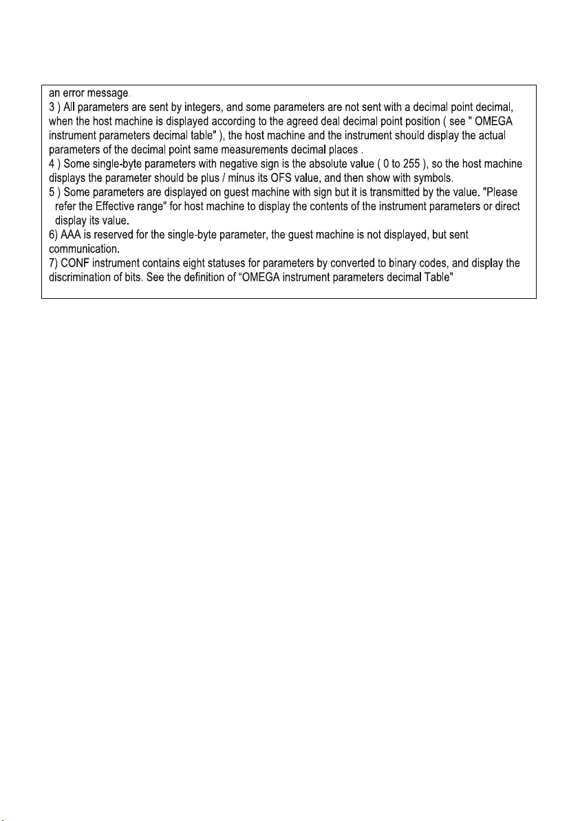
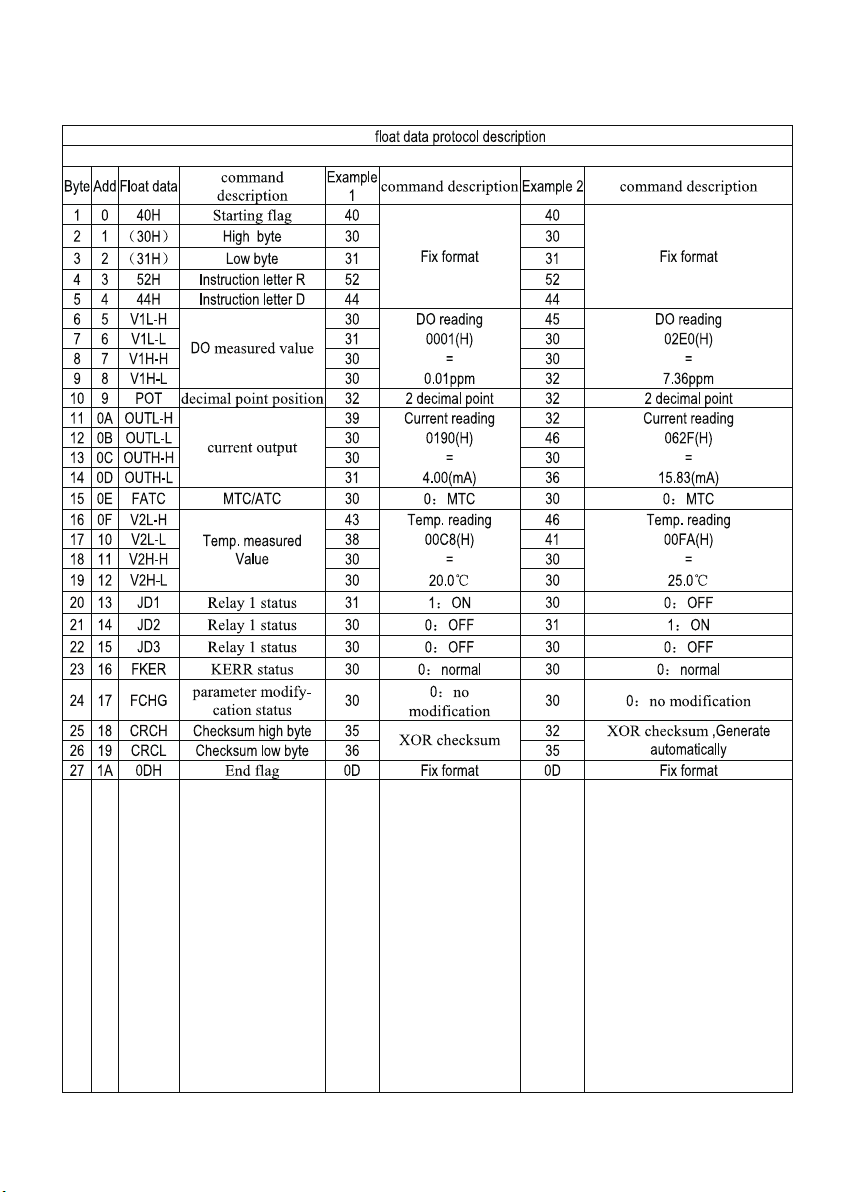
COMMUNICATION AGREEMENT
33
Page 39
34
Page 40
35
Page 41
36
Page 42
CDCN-961
37
Page 43
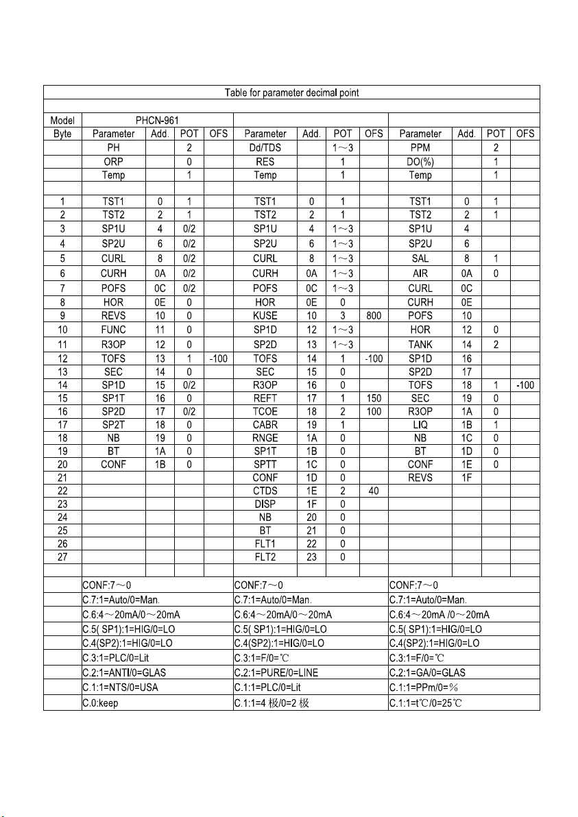
CDCN-961 DOCN-961
38
Page 44
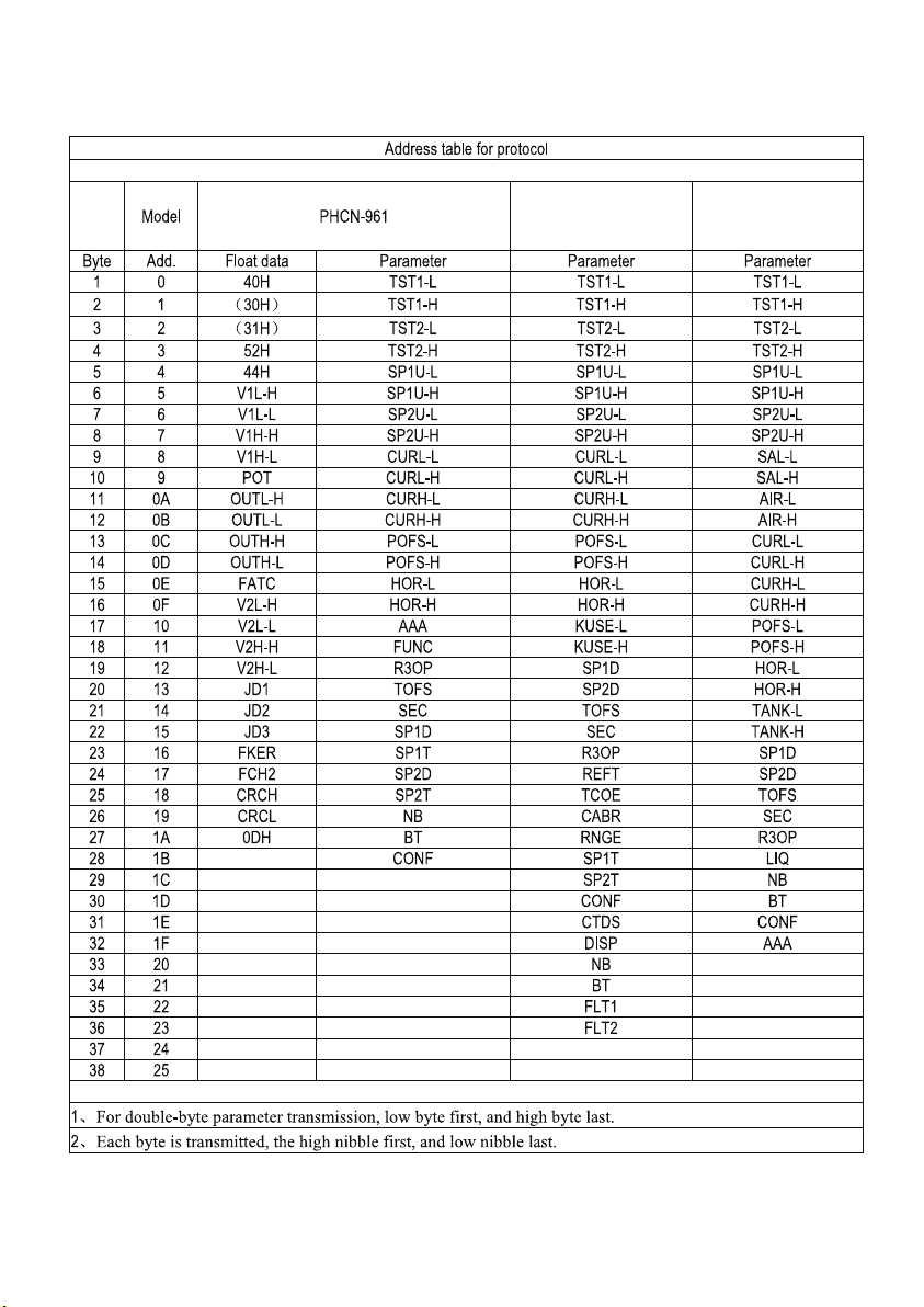
CDCN-961 DOCN-961
39
Page 45
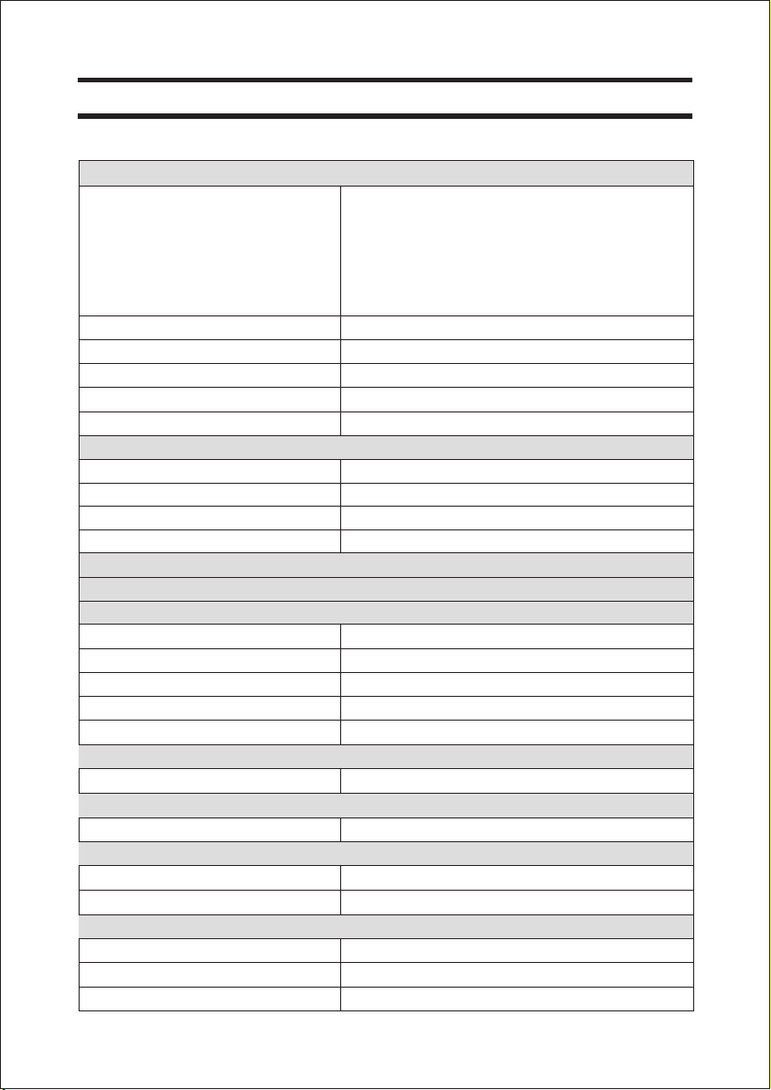
6 TECHNICAL PARAMETERS
6.1 TECHNICAL PARAMETERS FORM
CDCN-961 Transmitter / Controller
Measurement Range 0.000 to 3.000 μS/cm 0.000 to 3.000 ppm
Analytical degree & precision
Temperature
Analytical degree & precision
Temperature electrode
Temperature compensation Automatic ( ± 10 ℃ offset adjustment) / manual
Set point and control function
Control function Limited point
Cleaning circle
Cleaning time
Control hysteresis band 10%
Relay
RS-485
Electric current information and connection
Electric source
Signal output / load
Signal output load
Connection terminal
Main fuse wire
Alarm function
Function (switchable) Alarm, calibration remind, clean control
Display
LCD (liquid crystal display) Big-size screen of crystal display, orange back light
EMC Specification
Electromagnetic emission EN 50081-1
Electromagnetic induction EN 50082-1
Environmental conditions
Working temperature - 10 to 50 ℃ (14 to 122 ℉)
Humidity 10 to 95% (no frozen dew)
Protection grade NEMA 4X,IP 65
0.00 to 30.00 μS/cm 0.00 to 30.00 ppm
0.0 to 300.0 μS/cm 0.0 to 300.0 ppm
0 to 3.000 mS/cm 0 to 3.000 ppt
0 to 30.00 mS/cm 0 to 30.00 ppt
0 to 300.0 mS/cm 0 to 300.0 ppt
0.3 to 30.0 MΩ * cm
3 to 300.0 MΩ * cm
0.001 μS/cm , 0.1 MΩ * cm / ±1% full range
- 5.0 to 130 ℃
0.1 & ± 0.5 ℃
Pt-1000
From 1 to 999 hours
From 1 to 999 seconds
output
client program
220 V AC
0 / 4 - 20 mA isolated current output, can be set up freely
600 Ω
Connection terminal
Main fuse wire
40
Page 46
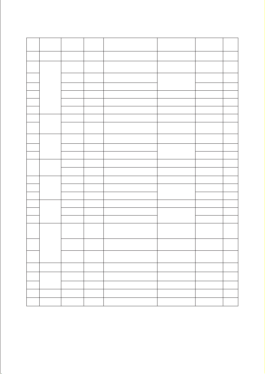
6.2 PARAMETER SETTING AND FACTORY PRELIMINARY VALUE
NO. Indication Parameter Symbol Contents Remark Valid range Factory
01 LOCK LOC Password function 0~200 0
02 ATC AtC Auto/Manual TEMP
P1
TC
03 TSET1 tSt1 TEMP set up of manual -10~100℃ 25.0
04 TSET2 tSt2 Calibration TEMP set
05 TOFS tOFS TEMP measurement offset Only valid for auto -10~10℃ 0. 0
06 LINE LINE TEMP line compensation LINE LINE
07
08 POFS POFS measurement value offset 000~20.00 0.00
P2 OFS
09
10 CTYP CtyP Type of current output 4
P3
CUr
11 CURL CUrL Low limit of transmitting output 0.00~40.00 0
12
SAL
14 SP1 SP1 Way set up of relay 1 HI /LO LO
P5
SP1
15 SP1U SP1U Setting value of relay 1 0.00~40.00 2.00
16
17 SP2 SP2 Way set up of relay 2 HI /LO HI
P6
SP2
18 SP2U SP2U Setting value of relay 2 0.00~40.00 6.00
19
20 R3OP R3OP Working mode of relay 3 OFF/SP1/SP2/
P7
rL3
21 IN HOr Interval (hour) valid for calibration
22
23 P8 CONF RNGE RNGE measurement range 1,2,3,4,5,6,7 5
24 NB nb Set ID number for 485 0-63 1
P9 DEF
25
26 NB nb Set ID number for 485 0-63 1
27 BT bt Communication rate 0-7 5
PURE PURE Pure temperature compensation
CABL CABL CABL Constant K=10.0 is
CURH CUrH High limit of transmitting output
LIT LIT Limitation control LIT13 P4
PLC PLC puls
SP1D SP1d Relay 1 hysteresis / proportion
SP2D SP2d Relay 2 hysteresis / proportion
DUR SEC Operating time (second) valid for cleaning
BT b Communication rate 0-7 5
compensation
e length contro
Only valid for manual
valid
ppm mode 0.01 unit
% mode is 0.1 unit
ppm mode 0.01 unit
% mode is 0.1 unit
ppm mode 0.01 unit
% mode is 0.1 unit
and cleaning mode
mode
ON/OFF OFF
0.0~60.0℃ 25.0
0.0~20.0 ohm 0.0
0/4~20mA
0.0~400.0 1000
0.00~2.00 0.10
0~2.00 0.10
ALL/CAL/CL
E
0-999 100
0-200 30
value
CAL
41
Page 47

7 GENERAL INFORMATION
WARRANTY
OMEGA ENGINEERING, INC. warrants this product to be free from significant
deviations in material and workmanship for a period of one year from the date of purchase. If
repair is necessary and has not been the result of abuse or misuse within the warranty period,
please return to OMEGA ENGINEERING, INC. and amendment will be made without any charge.
OMEGA ENGINEERING, INC. Customer Service Center will determine if product problem is due
to deviations or customer abuse. Out of warranty products will be repaired on a charge basis.
RETURN OF MALFUNCTION INSTRUMENTS
Authorisation must be obtained from OMEGA ENGINEERING, INC. Customer Service Center to
issue a RIR number before returning items for any reason. When applying for authorisation,
please include date requiring the reason of return. Instruments must be carefully packed to
prevent damage in shipment and insured against possible damage or loss.
OMEGA ENGINEERING, INC. will not be responsible for any damage resulting from careless or
insufficient packing.
Warring: Damage as a result of inadequate packaging is the User / distributor’s responsibility.
Please follow the guidelines below before transporting.
GUIDELINES OR RETURNING UNIT FOR REPAIR
Use the original packaging material, if possible when transporting back the unit for repair.
Otherwise wrap it with bubble pack and use a corrugated box for better protection. Include
a brief description of any faults suspected for the convenience of Customer Service Center,
if possible.
42
Page 48
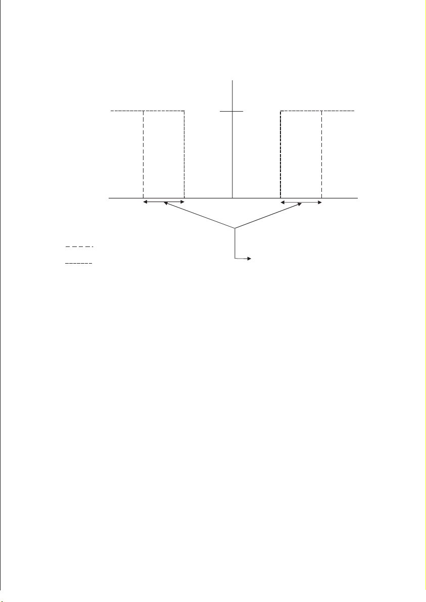
APPENDIX 3 – HYSTERESIS BAND
Simple Explanation on the Function of Hysteresis Band
SP1 Set to LO
SP2 Set to HI
RELAY ON
RELAY OFF
4.0 4.5 9.5 10.07.0
SP1 SP2
FORWARD DIRECTION
REVERSE DIRECTION
The controller relay activates when the set-point is reached. In the reverse direction, it closes.
Relay continues to be active till the value reaches the amount set by hysteresis band.
HYSTERESIS BAND
(DEFAULT = 0.01 mS)
43
Page 49

ACCESSORY 5 - ABBREVIATIONS IN FUNTION FORM
Character
MEA
CAL
ENT
OFS
SET
ATC
SP1
SP2
LO
HI
CNtr
LIt
PLC
RL3
OUT
CONF
CLE
Meaning
Measurement mode
Calibration mode
Confirm
Zero point offset
Set up
Automatic temperature
compensation
Set point 1
Set point 2
Low limit
High limit
Control
Output signal
Configuration
Clean
Glass electrode
Antimony electrode
USA standard buffer
Character
C
F
UNIT
PPt
LINE
PURE
RNGE
CABL
COND
TDS
RES
FLT1
FLT2
Meaning
Centigrade
Fahrenheit
Unit
Salty Unit
Temperature line
compensation
Pure temperature
compensation
Measurement range
CABL
Conductivity
TDS
Resistivity
Number filter 1
Number filter 2
44
Page 50

NOTES:
45
Page 51

WARRANTY/DISCLAIMER
OMEGA ENGINEERING, INC. warrants this unit to be free of defects in materials and
workmanship for a period of 13 months from date of purchase. OMEGA’s WARRANTY adds an
additional one (1) month grace period to the normal one (1) year product warranty to cover
handling and shipping time. This ensures that OMEGA’s customers receive maximum coverage
on each product.
If the unit malfunctions, it must be returned to the factory for evaluation. OMEGA’s Customer
Service Department will issue an Authorized Return (AR) number immediately upon phone
or written request. Upon examination by OMEGA, if the unit is found to be defective, it
will be repaired or replaced at no charge. OMEGA’s WARRANTY does not apply to defects
resulting from any action of the purchaser, including but not limited to mishandling, improper
interfacing, operation outside of design limits, improper repair, or unauthorized modification.
This WARRANTY is VOID if the unit shows evidence of having been tampered with or shows
evidence of having been damaged as a result of excessive corrosion; or current, heat, moisture
or vibration; improper specification; misapplication; misuse or other operating conditions
outside of OMEGA’s control. Components in which wear is not warranted, include but are not
limited to contact points, fuses, and triacs.
OMEGA is pleased to offer suggestions on the use of its various products. However,
OMEGA neither assumes responsibility for any omissions or errors nor assumes
liability for any damages that result from the use of its products in accordance with
information provided by OMEGA, either verbal or written. OMEGA warrants only
that the parts manufactured by the company will be as specified and free of defects.
OMEGA MAKES NO OTHER WARRANTIES OR REPRESENTATIONS OF ANY KIND
WHATSOEVER, EXPRESSED OR IMPLIED, EXCEPT THAT OF TITLE, AND ALL IMPLIED
WARRANTIES INCLUDING ANY WARRANTY OF MERCHANTABILITY AND FITNESS
FOR A PARTICULAR PURPOSE ARE HEREBY DISCLAIMED. LIMITATION OF LIABILITY:
The remedies of purchaser set forth herein are exclusive, and the total liability of
OMEGA with respect to this order, whether based on contract, warranty, negligence,
indemnification, strict liability or otherwise, shall not exceed the purchase price of
the component upon which liability is based. In no event shall OMEGA be liable for
consequential, incidental or special damages.
CONDITIONS: Equipment sold by OMEGA is not intended to be used, nor shall it be used: (1) as
a “Basic Component” under 10 CFR 21 (NRC), used in or with any nuclear installation or activity;
or (2) in medical applications or used on humans. Should any Product(s) be used in or with any
nuclear installation or activity, medical application, used on humans, or misused in any way,
OMEGA assumes no responsibility as set forth in our basic WARRANTY / DISCLAIMER language,
and, additionally, purchaser will indemnify OMEGA and hold OMEGA harmless from any
liability or damage whatsoever arising out of the use of the Product(s) in such a manner.
RETURN REQUESTS/INQUIRIES
Direct all warranty and repair requests/inquiries to the OMEGA Customer Service Department.
BEFORE RETURNING ANY PRODUCT(S) TO OMEGA, PURCHASER MUST OBTAIN AN
AUTHORIZED RETURN (AR) NUMBER FROM OMEGA’S CUSTOMER SERVICE DEPARTMENT (IN
ORDER TO AVOID PROCESSING DELAYS). The assigned AR number should then be marked on
the outside of the return package and on any correspondence.
The purchaser is responsible for shipping charges, freight, insurance and proper packaging to
prevent breakage in transit.
FOR WARRANTY RETURNS, please have the
following information available BEFORE
contacting OMEGA:
1. Purchase Order number under which
the product was PURCHASED,
2. Model and serial number of the product
under warranty, and
3. Repair instructions and/or specific
problems relative to the product.
OMEGA’s policy is to make running changes, not model changes, whenever an improvement is possible.
This affords our customers the latest in technology and engineering.
OMEGA is a registered trademark of OMEGA ENGINEERING, INC.
© Copyright 2016 OMEGA ENGINEERING, INC. All rights reserved. This document may not be copied, photocopied,
reproduced, translated, or reduced to any electronic medium or machine-readable form, in whole or in part, without
the prior written consent of OMEGA ENGINEERING, INC.
FOR NON-WARRANTY REPAIRS,
consult
OMEGA for current repair charges. Have the
following information available BEFORE
contacting OMEGA:
1. Purchase Order number to cover the
COST of the repair,
2. Model and serial number of theproduct, and
3. Repair instructions and/or specific problems
relative to the product.
Page 52

Where Do I Find Everything I Need for
Process Measurement and Control?
OMEGA…Of Course!
Shop online at omega.com
TEMPERATURE
MU
Thermocouple, RTD & Thermistor Probes, Connectors, Panels & Assemblies
MU
Wire: Thermocouple, RTD & Thermistor
MU
Calibrators & Ice Point References
MU
Recorders, Controllers & Process Monitors
MU
Infrared Pyrometers
PRESSURE, STRAIN AND FORCE
MU
Transducers & Strain Gages
MU
Load Cells & Pressure Gages
MU
Displacement Transducers
MU
Instrumentation & Accessories
FLOW/LEVEL
MU
Rotameters, Gas Mass Flowmeters & Flow Computers
MU
Air Velocity Indicators
MU
Turbine/Paddlewheel Systems
MU
Totalizers & Batch Controllers
pH/CONDUCTIVITY
MU
pH Electrodes, Testers & Accessories
MU
Benchtop/Laboratory Meters
MU
Controllers, Calibrators, Simulators & Pumps
MU
Industrial pH & Conductivity Equipment
DATA ACQUISITION
MU
Data Acquisition & Engineering Software
MU
Communications-Based Acquisition Systems
MU
Plug-in Cards for Apple, IBM & Compatibles
MU
Data Logging Systems
MU
Recorders, Printers & Plotters
HEATERS
MU
Heating Cable
MU
Cartridge & Strip Heaters
MU
Immersion & Band Heaters
MU
Flexible Heaters
MU
Laboratory Heaters
ENVIRONMENTAL
MONITORING AND CONTROL
MU
Metering & Control Instrumentation
MU
Refractometers
MU
Pumps & Tubing
MU
Air, Soil & Water Monitors
MU
Industrial Water & Wastewater Treatment
MU
pH, Conductivity & Dissolved Oxygen Instruments
SM
M5557/0216
 Loading...