

Page 1
Conductivity/Resistivity
User’s Guide
C1 23.45 uS/cm
C2 .72 uS/cm
Relay 1
Relay 2
ENTER
Shop online at
omega.com
e-mail: [email protected]
For latest product manuals:
www.omegamanual.info
SM
CDCN-91 DUAL CHANNEL
Conductivity/Resistivity Controller
Page 2

omega.com [email protected]
Servicing North America:
U.S.A. Omega Engineering, Inc.
Headquarters: Toll-Free: 1-800-826-6342 (USA & Canada only)
Customer Service: 1-800-622-2378 (USA & Canada only)
Engineering Service: 1-800-872-9436 (USA & Canada only)
Tel: (203) 359-1660 Fax: (203) 359-7700
e-mail: [email protected]
For Other Locations Visit omega.com/worldwide
The information contained in this document is believed to be correct, but OMEGA accepts no liability for any errors it contains, and reserves
the right to alter specifications without notice.
Page 3
CDCN-91/CDCN-91AC
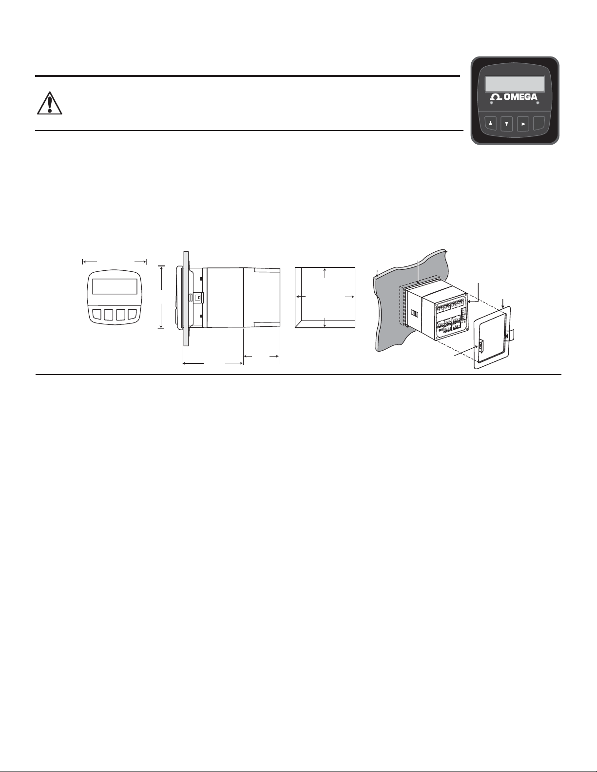
102 mm
(4.0 in.)
56 mm
(2.2 in.)
96mm (3.8 in.)
96 mm
(3.8 in.)
Panel Cutout
92 x 92 mm
( 0.8, - 0 mm)
3.6 x 3.6 in.
(0.031, -0 in.)
Optional
Rear Cover
quick-clip
gasket on
front side
of panel
panel
terminals
mounting
bracket
RELA 1
RELA 2
RELA 3
RELA 4
N/C
N/O COM N/C
N/O
COM
N/C
N/O
COM
N/C
N/O
COM
REA
OEN
CO
- OPEN COLL 4
-
OPEN COLL
3
SHLD
ISO ND
TEMP 1
SNL 1
SHLD
ISO ND
TEMP 2
SNL 2
POWER
OUTUT OTION
N
Conductivity/Resistivity
C1 23.45 uS/cm
C2 .72 uS/cm
Relay 1
Relay 2
ENTER
Dual Channel Conductivity/Resistivity Controller
CAUTION!
• Remove power to unit before wiring input and output connections.
• Follow instructions carefully to avoid personal injury.
• This product should only be used for the purposes and in the manner described in this manual.
Installation
1. Punch out panel and de-burr edges. Recommended clearance on all sides between instruments is 1 inch.
2. Place gasket on instrument, and install in panel.
3. Slide mounting bracket over back of instrument until quick-clips snap into latches on side of instrument.
4. Connect wires to terminals.
5. To remove, secure instrument temporarily with tape from front or grip from rear of instrument. DO NOT RELEASE. Press
quick-clips outward and remove.
6. If cleaning is necessary, wipe the front of the unit with a damp cloth.
7. The live contacts on the back of this unit must be covered to avoid accidental shock hazard.
Specifi cations
General
Compatible electrodes: Omega CDCN-91 Series Standard and
Certifi ed Series Conductivity/Resistivity Electrodes
Enclosure:
• Rating: NEMA 4X/IP65 front
(NEMA 4X Rear cover available)
• Case: PBT
• Panel case gasket: Neoprene
• Window: Polyurethane-coated polycarbonate
• Keypad: Sealed 4-key silicone rubber
• Weight: CDCN-91AC: 1.28 lb/0.58 kg
CDCN-91: 1.2 lb/0.55 kg
Display Alphanumeric 2 x 16 LCD
• Contrast: User selected, 5 levels
• Update rate: 1.5 seconds
Sensor input range:
• Conductance: 0.055 S/cm to 400.00 mS/cm
• Resistivity: 10 K/cm to 18.26 M/cm
• TDS: 0.0 to 999999 ppm
• Temperature: 25 to 120 °C (-13 to 248 °F) PT 1000;
25 ºC = 1096
Accuracy:
• Conductivity/Resistivity: ± 2% of reading
• Temperature: ± 0.5 ºC (0 to 100 ºC)
Electrical
Power requirements:
CDCN-91AC: 100 to 240 VAC ± 10% , 50-60 Hz, 20VA or
11 to 24 VDC ±10%, regulated, 0.5 A max
CDCN-91: 11 to 24 VDC ±10%, regulated, 0.5 A max
Current outputs (3 available):
• 4 to 20 mA, isolated, fully adjustable and reversible
• Max loop impedance:
150 @ 12 V, 450 @ 18 V, 750 @ 24 V
• Update rate: 100 mS
• Accuracy: ±0.03 mA @ 25°C, 24 VDC
Open-collector outputs (2 available, optically isolated):
• 50 mA sink or source, 30 VDC max. pull-up voltage
• Programmable for:
• High or Low setpoint with adjustable hysteresis
• Pulse operation (max. rate: 400 pulses/min)
• USP standards
• Time delay: 0 to 6400 s.
Relay outputs (up to 4 SPDT relays available)
• Maximum resistive load: 5 A @ 250 VAC, 5 A @ 30 VDC
• Isolation: 500 V minimum
• Programmable for:
• High or Low setpoint with adjustable hysteresis
• Pulse operation (max. rate: 400 pulses/min)
• USP standards
• Time delay: 0 to 6400 s.
Environmental
• Ambient operating temp: -10 to 55 °C (14 to 131 °F)
• Storage temperature: -15 to 80 °C (5 to 176 °F)
• Relative humidity: 0 to 95%, non-condensing
• Maximum altitude: 2000 m (6562 ft)
• Insulation category: II
• Pollution degree: 2
Standards and Approvals
• CE, UL listed
• Immunity: EN50082-2
• Emissions: EN55011
• Safety: EN61010
• Manufactured under ISO 9001, ISO 14001
1Omega CDCN-91 Dual-Channel Controller
Page 4
Electrical Connections
PLC or Recorder
Power
Supply
12-24 VDC
+
-
Loop 1
Loop 2
Loop 3
+
++
-
-
-
Channel 3
4-20 mA in
Channel 1
4-20 mA in
+
-
Channel 2
4-20 mA in
+
-
+
-
CDCN-91 4 to 20 mA outputs
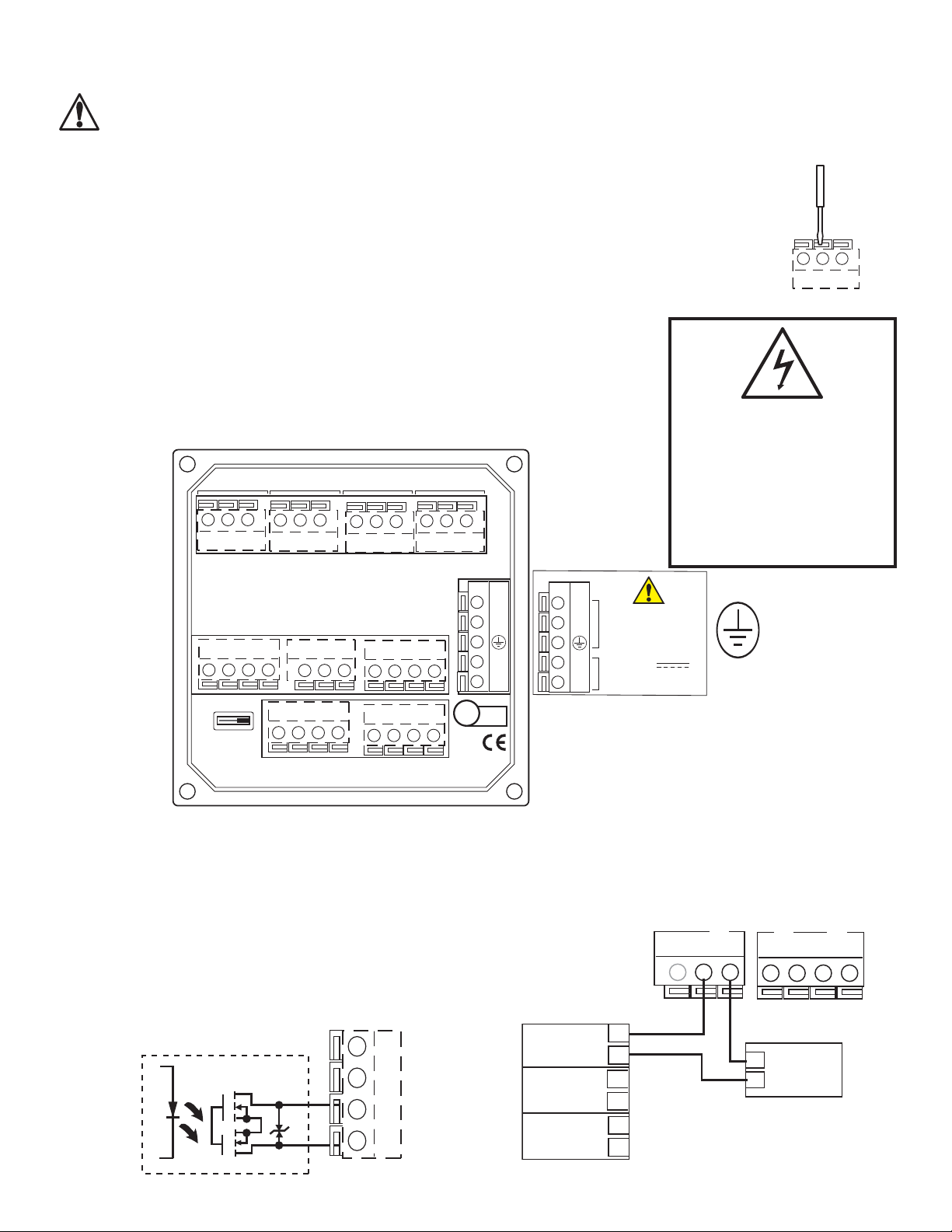
CAUTION: Failure to fully open terminal jaws before removing wire may permanently damage instrument.
This product must be provided with a means to disconnect all current carrying conductors connected to the main AC line, or,
as part of the building installation.
Wiring Procedure
1. Remove 0.35- 0.47 in. (9-12 mm) of insulation from wire end.
2. Press the orange terminal lever downward with a small screwdriver to open terminal jaws.
3. Insert exposed (non-insulated) wire end in terminal hole until it bottoms out.
4. Release orange terminal lever to secure wire in place. Gently pull on each wire to ensure a good connection.
Wiring Removal Procedure
1. Press the orange terminal lever downward with a small screwdriver to open terminal jaws.
Wiring Tips:
• Do not route sensor cable in conduit containing AC power wiring - electrical noise may
interfere with sensor signal.
• Routing sensor cabling in grounded metal conduit may prevent moisture damage, electrical
noise, and mechanical damage.
• Seal cable entry points to prevent moisture damage.
• Do not insert two wires into a single terminal. If necessary, splice the wires together before
inserting into the terminal.
RA 1
NC NO CO NC NO CO NC NO CO NC NO CO
RA 2
RA 3 RA 4
POWR
Electrical shock hazard exists!
Never connect live AC lines to the
instrument.
Always connect a ground wire to
the ground terminal when using
AC power.
Caution:
- OPN CO 4
OTPT OPTION
RA 3,4
OPN CO 3
OPN CO 3
OPN CO 4
-
OPN
CO 3,4
SD
ISO GND
OOP 1
OOP 1
-
TP 1
OOP 2
-
SGN 1
SD
OOP 2
ISO GND
OOP 3
OOP 3
-
SGN 2
TP 2
Output Option Switch
• In OPEN COLLECTOR position, relays 3 and 4 are open
collector outputs as shown.
• In RELAY 3, 4 position, relays 3 and 4 are dry contact relays
identical to relays 1 and 2.
• The menu references in the CDCN-91 display will not change.
Outputs 3 and 4 will be identifi ed as "Relay" regardless of
switch setting.
Internal open-collector
output circuit
Outputs
-
R9239
N
-
ISTD
171559
100 - 240
N
50-0, 20A
-
11 - 24
0.5 A
*
4 to 20 mA loop Outputs
The current loops in the CDCN-91 are passive circuits.
12-24 VDC must be provided from an external source.
A single loop is illustrated for clarity.
2 Omega CDCN-91 Dual-Channel Controller
+
-
+
Page 5
Sensor Input Connections
RED
HTE
LAC
SLER (SHLD)
SHLD
SO ND
TEMP 2
SNL 2
SHLD
SO ND
TEMP 1
SNL 1
RED
HTE
LAC
SLER (SHLD)
Hysteresis
ie
Low Setpoint
Process
Hysteresis
Output actie
Output inactie
ie
High Setpoint
Process
Relay 1 Rng: uS
10.00 -- 5.00
Relay 1 PlsRate:
100 Pulses/min
Pulse rate
S
pulses
pulses
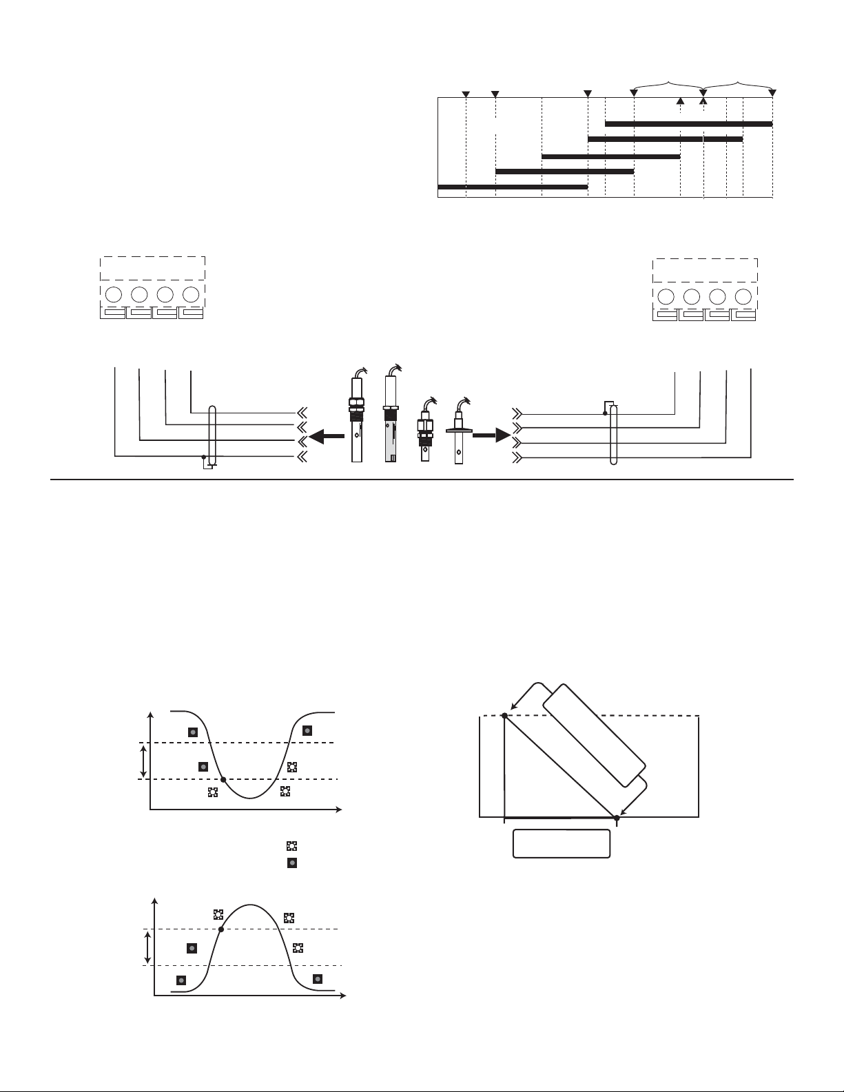
• The CDCN-91 will accept two independent sensor input
signals. The two sensors may be of different cell constant
values.
• Do not route sensor cable in any conduit containing AC power
wiring - electrical noise may interfere with the signal.
• Use three conductor shielded cable for cable extensions up
to 30 m (100 ft) max. for measurements below 10 M (above
0.10 S).
• Maximum cable length for resistivity measurements above
10 M is 25 ft, and solution temperatures must be between
20 °C and 100 °C.
0.010mS
100 MΩ
UPW @ 25°C
CDCE-90-001
0.054mS
18.3 MΩ
Bottled
USP
Rinse
Water
CDCE-90-01 ( 0.10 Cell)
1mS
1MΩ
10mS
100KΩ
Water
CDCE-90-20
CDCE-90-10 (10.0 Cell)
CDCE-90-1 (1.0 Cell)
(0.01 Cell)
100mS
200mS
10KΩ
Cooling Tower
Waste Waters
Brackish Sea Water
(Salinity)
1,000mS 10,000mS
Deionization Regen. Chemicals
Alkali Cleaners, Acids/Bases
(20.0 Cell)
200,000mS
400,000mS
50,000mS
100,000mS
Relay and Open Collector Functions
The CDCN-91 is equipped with four SPDT relays that can be
confi gured for High alarm, Low alarm, Proportional Pulse or
USP operation.
• Low: Output triggers when process variable is less than
setpoint.
• High: Output triggers when process variable is higher than
setpoint.
• Off: Disables output pulse.
• Pulse Operation
The output emits a 100 mS pulse at a rate defi ned by the
Source, Pulse Range and Max PlsRate settings, and by the
process condition. The maximum pulse rate is 400 pulses
per minute.
Example: As the process falls below 10 S the output will
start pulsing in relation to the process value, the max pulse
endpoint and the programmed pulses/min. The pulse rate
will increase as the process approaches the programmed
endpoint.
The Pulse Rate determines what the maximum rate will be.
The CDCN-91 maximum capability is 400 pulses per minute.
The RANGE defi nes where the pulsing starts and where it
reaches the maximum rate.
10 S = 0 pulses/min.
7.5 S = 50 pulses/min.
5 S = 100 pulses/min.
3Omega CDCN-91 Dual-Channel Controller
Page 6
VIEW menu
• During normal operation, the CDCN-91 displays the VIEW menu.
• When using the CALIBRATE or OPTIONS menus, the CDCN-91 will return to the VIEW menu if no activity occurs for 10 minutes.
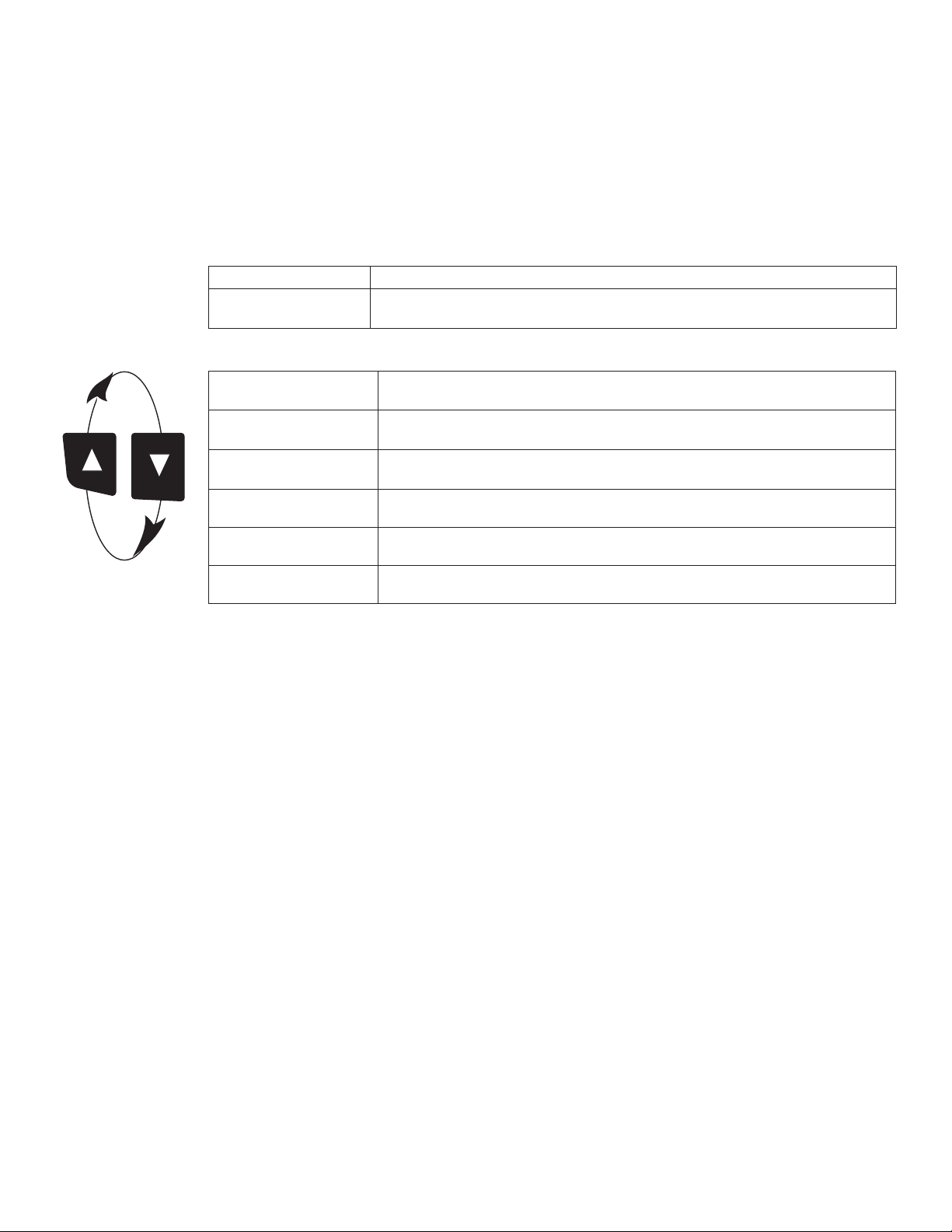
• To select the item you want displayed, press the UP or DOWN arrow keys. The items will scroll in a continuous loop. Changing the
display selection does not interrupt system operations.
• No keycode is necessary to change display selection.
• Output settings cannot be edited from the VIEW menu.
View Menu
Display Description
C1 1000.00 μS/cm
C2 30.00 μS/cm
The VIEW displays below are temporary. The permanent display will return after 10 minutes.
Monitor C1 Conductivity and C2 Conductivity simultaneously. This is the
permanent display when Channel 2 is ON.
C1 1000.00 μS/cm
25.0 °C
C2 30.00 μS/cm
25.0 ºC
Ratio C1: C2
97.00%
Loop 1 12.03 mA
Loop 2 5.69 mA
Loop 3 13.7 mA
R3 ON R4 PLS
Last CAL:
6-30-00 >
Monitor Channel 1 Conductivity and Channel 1 Temperature. This is the
permanent display when Channel 2 is OFF.
Monitor Channel 2 Conductivity and Channel 2 Temperature. This view is
available only when Channel 2 is ON.
Monitor Percent Reject, Difference, or Ratio (Channel 1 to Channel 2 or
Channel 2 to Channel 1)
Monitor Loop 1 and Loop 2 current output simultaneously.
Monitor Loop 3 and status of Relays 3 and 4 (Open Collector 3 and 4).
Display date for scheduled maintenance or date of last calibration.
4 Omega CDCN-91 Dual-Channel Controller
Page 7
CDCN-91 Editing Procedure:
Relay1 Setpnt:
20.00 uS
Relay1 Setpnt:
10.00 uS
ENTER
Relay1 Setpnt:
1
0
.00 uS
Relay Setpnt:
1
9
.00 uS
Relay1 Setpnt:
Saving
Relay1 Setpnt:
19.00 uS >
20.00 us >
Relay 1 Setpnt:
Standard >
Chan 1 Cell:
CALIBRATE: ----
Enter Key Code
CALIBRATE: *---
Enter Key Code
CALIBRATE: **--
Enter Key Code
CALIBRATE: ***-
Enter Key Code
Standard >
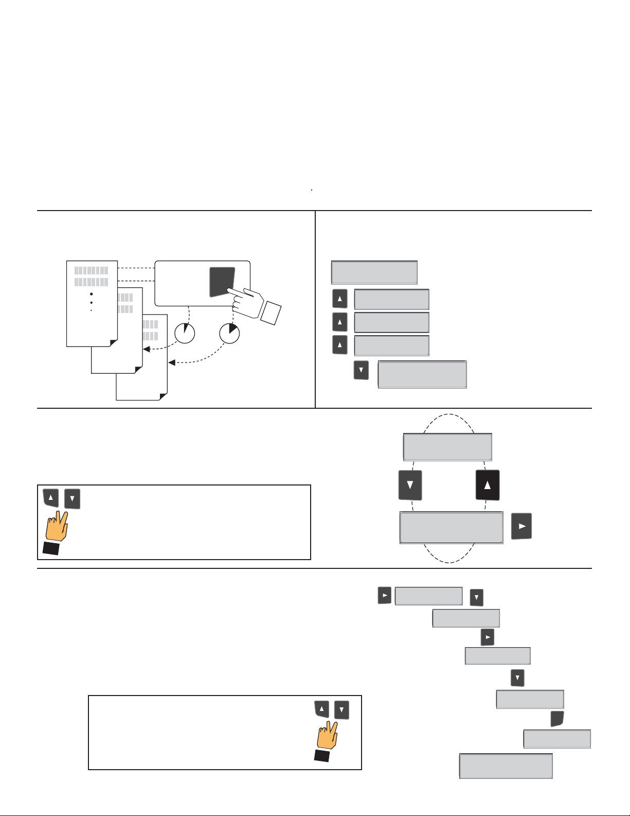
Step 1. Press and hold ENTER key:
• 2 seconds to select the CALIBRATE menu.
• 5 seconds to select the OPTIONS menu.
Step 2. The Key Code is UP-UP-UP-DOWN keys in sequence.
• After entering the Key Code, the display will show the fi rst item in the selected menu.
Step 3. Scroll menu with UP or DOWN arrow keys.
Step 4. Press RIGHT ARROW key to select menu item to be edited.
• The fi rst display element will begin fl ashing.
Step 5. Press UP or DOWN keys to edit the fl ashing element.
• RIGHT ARROW key advances the fl ashing element.
Step 6. Press ENTER key to save the new setting and return to Step 3.
Notes on Step 1:
• The View Menu is normally displayed.
• The CALIBRATE and OPTIONS menus require a KEY CODE.
Press
hold for
access
IEW
ENTER
Notes on Step 2:
If no key is pressed for 5 minutes while display is showing "Enter
Key Code", the display will return to the VIEW menu.
2s 5s
CAIRATE
OPTIONS
Notes on Steps 3 and 4:
• Refer to following pages for complete listing of menu items and their use.
• From the Step 3 display, pressing the UP and DOWN keys simultaneously will
return the display to the VIEW menu.
• If no key is pressed for 10 minutes, display will also return to the VIEW menu.
Step 3: Finished Editing?
Press the UP and DOWN keys simultaneously after
saving the last setting to return to normal operation.
First item in CALIBRATE
menu
Step 3
Step 4
Notes on Steps 5 and 6:
• All output functions remain active during editing.
• Only the fl ashing element can be edited.
• RIGHT ARROW key advances the fl ashing element in a continuous loop.
• Edited value is effective immediately after pressing ENTER key.
• If no key is pressed for 10 minutes unit will restore the last saved value and return to step 3.
• Step 6 (pressing ENTER key) always returns you to Step 3.
• Repeat steps 3-6 until all editing is completed.
Step 5: Made an Error?
Press the UP and DOWN keys simultaneously
while any element is fl ashing. This will recall the
last saved value of the item being edited and
return you to Step 3.
Step 5
Step 6
5Omega CDCN-91 Dual-Channel Controller
Page 8
Calibrate Menu
Display
(Factory settings shown)
Chan 1 Cell:
Standard >
Chan 1 Cell:
1.0 >
Cell: Custom
1.0000 >
Chan 1 Set:
Temperature >
Chan 1 Set:
Conductivity >
Chan 1 Units:
uS/cm >
Chan 1 TDS:
2.0000 uS/PPM >
Function:
Reject C1 → C2 >
Loop 1 Source:
Chan 1 Cond >
Loop 1 Range: uS
0.0000 → 100.000 >
Relay 1 Mode:
Low >
Relay 1 Source:
Chan 1 Cond >
Relay 1 Setpnt:
10.0000 uS >
Relay 1 Hys:
0.5000 uS >
Relay 1 Delay:
10.0 secs >
Relay 1 Rng: uS
10.0000 → 40.0000 >
Relay 1 PlsRate:
120 Pulses/Min >
Last CAL:
6-30-00 >
Description
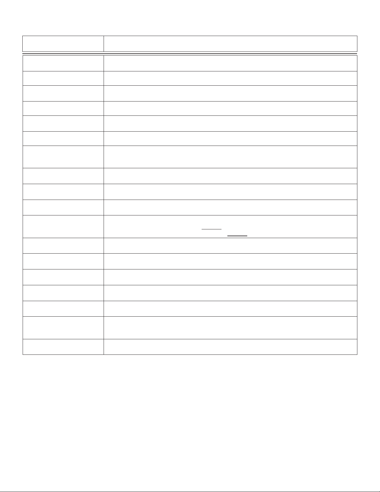
Select CUSTOM only if you are connecting a certifi ed conductivity sensor. Select STANDARD for all
non-certifi ed sensors.
For STANDARD sensors: Select the nominal cell constant: 0.01, 0.1, 1.0, 10.0 or 20.0.
For CUSTOM sensors: Enter the precise cell constant from the certifi cate provided with your sensor,
or from the information label on the sensor.
Adjust the temperature of the system based on an accurate external reference.
This single-point wet calibration procedure requires a test solution of known value.
Enter all zeroes here to restore TEMPERATURE and CONDUCTIVITY to factory calibration.
Select the units of measure: S/cm, mS/cm, k•cm, M•cm, PPB, PPM
If the Units selection is PPM or PPB, set the ratio of S to PPM of Total Dissolved Solids. The factory
preset value is 2 S per 1 PPM of TDS. (Always S/PPM, even if units is PPB).
See page 10 for additional information.
Select a functional relationship between C1 and C 2: • Ratio is (C1:C2) or (C2:C1)
• Percent Reject is 100%(1-C2/C1) or 100%(1-C1-C2) • Difference is (C1-C2) or (C2-C1)
Select the measured value or calculated FUNCTION you want Loop 1 to represent:
Chan 1 Cond, Chan 2 Cond, Chan 1 Temp, Chan 2 Temp, or Function.
Set the minimum (4 mA =) and maximum (20 mA =) range for Loop 1.
Make sure that the values are consistent with the units of the source.
Select operating mode for Relay 1: OFF, LOW, HIGH, USP or PULSE.
For USP mode: • Relay 1 SOURCE must be Cond 1 or Cond 2
• Temp Comp (Options menu) must be set to None
Select the INPUT SIGNAL (or FUNCTION) monitored by Relay 1:
• Cond 1 • Cond 2 • Temp 1 • Temp 2 • Function
Set Relay 1 activation point. The maximum value acceptable is 999999.
USP setpoints are high alarms, where the setpoint is a percentage below the USP limit.
Relay 1 will be deactivated at setpoint ± Hysteresis (depending on High or Low selection).
When the relay Mode is USP (defi ned as a HIGH alarm), Hysteresis is displayed in S.
Set up to 6400 seconds delay time for relay response.
Relay 1 will be activated only if the source value exceeds the setpoint for this time period.
If Relay 1 is PULSE mode, set the start and end point of the conductivity range and also set the
maximum pulse rate. (The maximum PULSE rate setting is 400 pulses per minute.)
The combined Relay 1 Range and Pulse rate settings shown here indicate:
"Start pulsing when the conductivity value is 10 S and increase the pulse rate up to the maximum
of 120 pulses per minute when the conductivity value reaches 40 S."
Use this “note pad” to record important dates, such as annual recertifi cation or scheduled
maintenance.
• All changes in this menu become effective when saved, except the "Set Cond" and "Set Temp" settings.
• All outputs affected by a change in the "Set Cond" and "Set Temp" settings are frozen until you exit the Calibrate menu.
6 Omega CDCN-91 Dual-Channel Controller
Page 9
USP Limits
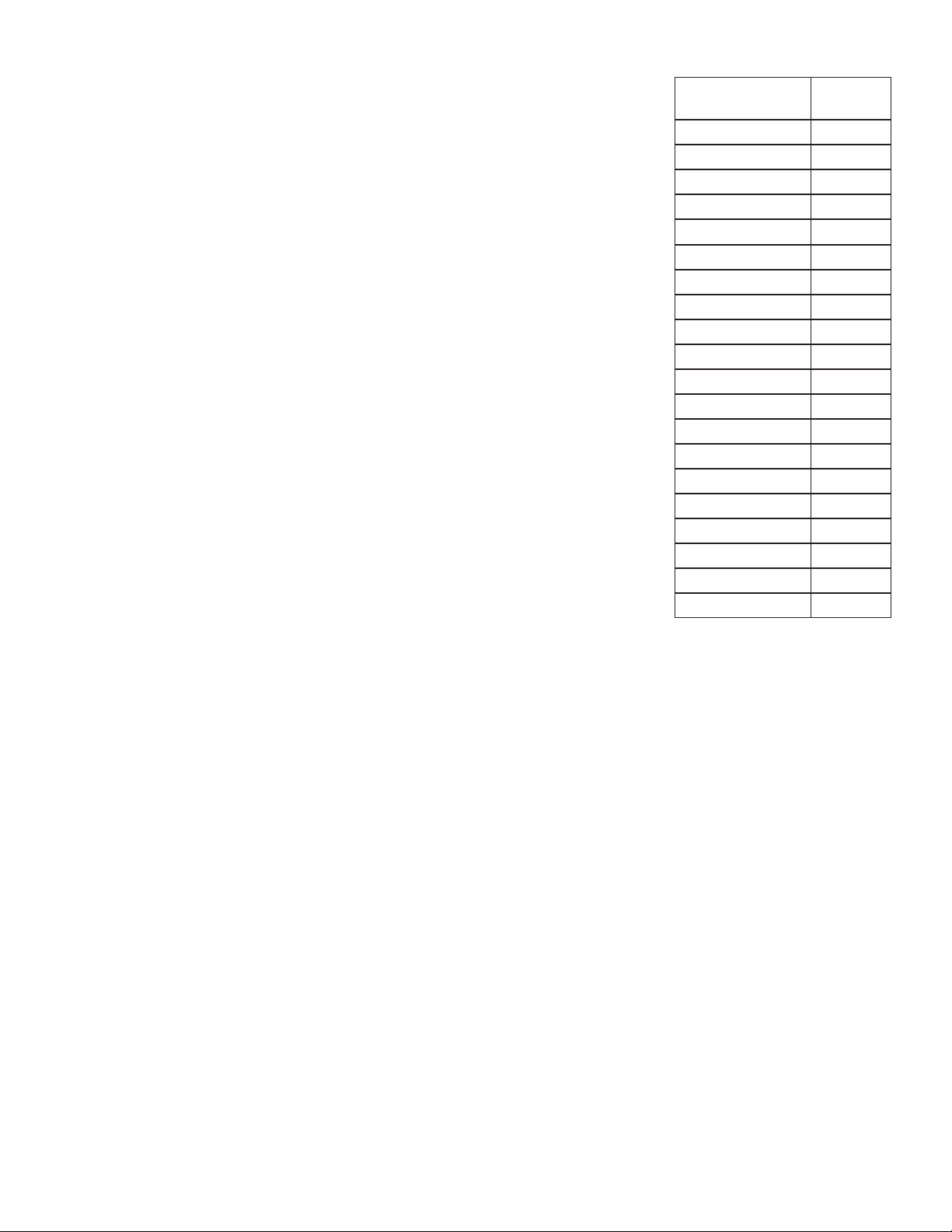
USP (United States Pharmacopoeia) has defi ned a set of conductivity values (limits) to be used
for pharmaceutical water monitoring. This standard requires non-temperature compensated
conductivity measurement be used to warn if the conductance approaches the USP limit. The
limits vary according the temperature of the sample.
The CDCN-91 has the USP limits stored in memory. It will automatically determine the proper
USP limit based on the measured temperature.
Using the USP function
In the CDCN-91, USP setpoints are defi ned as a percentage below the USP limit, so a USP
alarm is always a HIGH alarm. The CDCN-91 can be set to warn you if the conductivity
approaches within a set percentage of the USP limit.
The following settings and conditions are required for a USP relay function:
1. In the CALIBRATE menu:
• RELAY MODE must be set to USP.
• RELAY SOURCE must be Chan 1 or Chan 2 Cond.
• SOURCE UNITS must be set to μS.
2. In the OPTIONS menu:
• The TC Mode of the USP channel must be set to None.
(Service tip: If a relay is constantly on, check these settings.)
Example:
• The USP setpoint is 40%.
• The water temperature is 19 ºC, so the USP limit is 1.0 S.
• The relay will be activated when the conductivity value reaches 0.6 S, or 40% below the 1.0
USP limit.
• If the water temperature drifts to more than 20 ºC, the CDCN-91 will automatically adjust
the USP limit to 1.1.
• The relay will now be activated when the conductivity value reaches 40% below 1.1S,
or 0.66 S.
Temperature
range is: (ºC)
USP limit
is: (μS)
0 to < 5 0.6
5 to < 10 0.8
10 to < 15 0.9
15 to < 20 1
20 to < 25 1.1
25 to < 30 1.3
30 to < 35 1.4
35 to < 40 1.5
40 to < 45 1.7
50 to < 55 1.8
55 to < 60 2.1
60 to < 65 2.2
65 to < 70 2.4
70 to < 75 2.5
75 to < 80 2.7
80 to < 85 2.7
85 to < 90 2.7
90 to < 95 2.7
95 to < 100 2.9
100 to < 105 3.1
7Omega CDCN-91 Dual-Channel Controller
Page 10
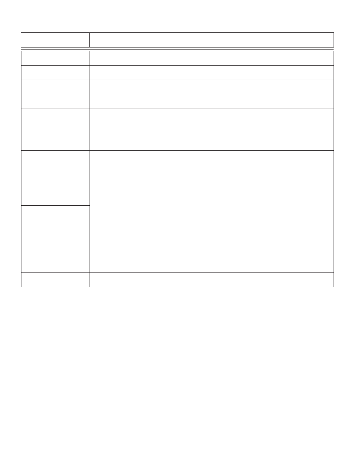
Options Menu
Display
(Factory settings shown)
Contrast:
3 >
Temp Display:
°C >
Channel 2:
On >
Power:
60 Hz >
Chan 1 TC Mode:
Linear >
Chan 1 TC Slope:
0.00 % >
Averaging:
Off >
Chan 1 Decimal:
*.**** >
Loop 1 Adjust:
4.00 mA >
Loop 1 Adjust:
20.00 mA >
Description
Adjust the LCD contrast for best viewing. A setting of 1 is lower contrast, 5 is higher.
In general, select lower contrast if the display is in warmer ambient surroundings.
Select ºC or ºF.
Turn CH 2 OFF if not in use. This will remove all menu functions related to CH 2.
Select 50 Hz or 60 Hz electrical noise suppression, according to the AC power used in your area.
Select the proper setting for all applications, whether AC or DC powered.
Set the method for temperature compensation to NONE, LINEAR or PURE WATER. You must select
NONE for USP systems. Select LINEAR for applications where the water is less than 5 M (or greater
than 0.2 S). Select PURE WATER for applications where the water is greater than than 5 M (or less
than 0.2 S).
For LINEAR or PURE WATER temperature compensation, select a % per ºC slope. Maximum slope
setting is 9.99 % per ºC. If Temp Comp setting is NONE, this item will not be displayed.
OFF provides the most instantaneous response to process changes. Select LOW (4 sec) or HIGH
(8 sec) averaging if your process experiences frequent or extreme fl uctuations.
Set the decimal to the best resolution for your application. The display will automatically scale up to
this restriction. Select *****., ****.*, ***.** **.*** or *.****
Adjust the minimum and maximum current output. The display value represents the precise current
output. Adjustment limits:
• 3.80 mA < 4.00 mA > 5.00 mA
• 19.00 mA < 20.00 mA > 21.00 mA
Use this setting to match the system output to any external device.
These settings repeat for Loop 2 and Loop 3.
Select active HIGH or active LOW operation for relay 3.
Relay 3 Active:
High >
Test Loop 1:
>
Test Relay 1:
>
Notes:
Channel settings will repeat when Channel 2 is enabled.
Loop settings will repeat for Loop 2 and Loop 3.
Check setting for related values when making changes (for example, if temp is set for ºC with a temp alarm at 25 ºC, and you change
the temp display to ºF, be sure to change the alarm setpoint to 77 ºF.)
Relay settings will repeat for Relays 2, 3 and 4 (except "Relay Active" selection; applies to Relay 3 and 4 only.)
Recommended: Use active LOW if relay 3 is set for OPEN COLLECTOR operation.
Active HIGH: Power is applied to relay coil when process value reaches SETPOINT.
Active LOW: Power is removed from relay coil when process value reaches SETPOINT.
Press UP and DOWN keys to manually change Loop 1output current.
Limits are 3.6 mA to 21.00 mA. Hold UP or DOWN keys to scroll the output value.
Press UP and DOWN keys to manually toggle the relay state.
8 Omega CDCN-91 Dual-Channel Controller
Page 11

Calibration Procedure
The CDCN-91 has been electronically calibrated at the factory.
• Procedure A verifi es the accuracy and linearity of the CDCN-91 by simulating temperature and conductivity values with precision
(±0.1%) fi xed resistors.
• Procedure B is a wet calibration. This procedure uses the sensor input and NIST traceable test solutions. When done correctly, this
procedure offers the most accurate system calibration.
A) Accuracy Verifi cation with Precision Resistors (Electronic Calibration):
1. Simulate the Temperature
The temperature input to the CDCN-91 is a PT-1000 thermistor, where 1000 Ohms () is equal to 0 ºC and a change of 3.84
equals a 1 ºC change. (1000 = 0 ºC, 1003.84 = 1.0 ºC, 1007.68 = 2.0 ºC … 1096 = 25 ºC)
• Connect a resistor (1000 to 1096 ) between "Temp" and "Iso. Gnd" terminals.
• Set Temp; Adjust the temperature to exact value based on the measured resistance. (See Editing Procedure, Calibrate menu.)
• To verify the CDCN-91 temperature linearity, connect a second resistor value to the terminals.
• If the CDCN-91 does not display the correct value ( ± 0.5 ºC), service is required.
2. Simulate the Conductivity
You may calculate the exact Resistance needed to simulate a specifi c conductivity value , or you may calculate the exact
Conductivity based on a resistor value:
Resistance =
Cell constant
conductivity (Siemens*) 0.000020 (Siemens*)
e.g.
0.1 cell constant
= 5,000 or 5 K
Conductivity =
(*1 S = 1 X 10
Cell constant
conductivity (Siemens*) 100,000 ()
-6
Siemens or 0.000001 Siemens)
e.g.
0.1 cell constant
= 0.000001 Siemens*
or 1S/cm
• Connect the conductivity resistor between the "Sgnl 1 " and "Iso Gnd" (or Sgnl 2 and Iso Gnd) terminals.
• Set Cond: Adjust the conductivity value based on the resistor value. (See Editing Procedure and Calibrate menu.)
• Verify the linearity of the CDCN-91 by connecting a second Conductivity resistor of a different value.
• If the CDCN-91 does not display the correct value (±2% of reading), service is required.
B) Wet Calibration with NIST Traceable Solutions:
When using NIST traceable standards, review the temperature information provided with the test solution. Prevent contamination of
the test solution. The sensor must be at the temperature specifi ed on the test solution label.
• Remove the sensor from the system. Rinse the sensor in a small amount of test solution.
• Place the sensor into the test solution.
• Place a reference thermometer into the same solution.
• Allow suffi cient time for the temperature to stabilize.
• Set Temp: Adjust the temperature value based on the reference thermometer. (See Editing Procedure.)
• Set Cond: Adjust the conductivity value based on the test solution value. (See Editing Procedure.)
• Verify the linearity of the CDCN-91 by placing the sensor into a second test solution of a different value.
• If the CDCN-91 does not display the correct value (Temperature ±0.5 ºC, Conductivity ±2% of reading), service is required.
9Omega CDCN-91 Dual-Channel Controller
Page 12
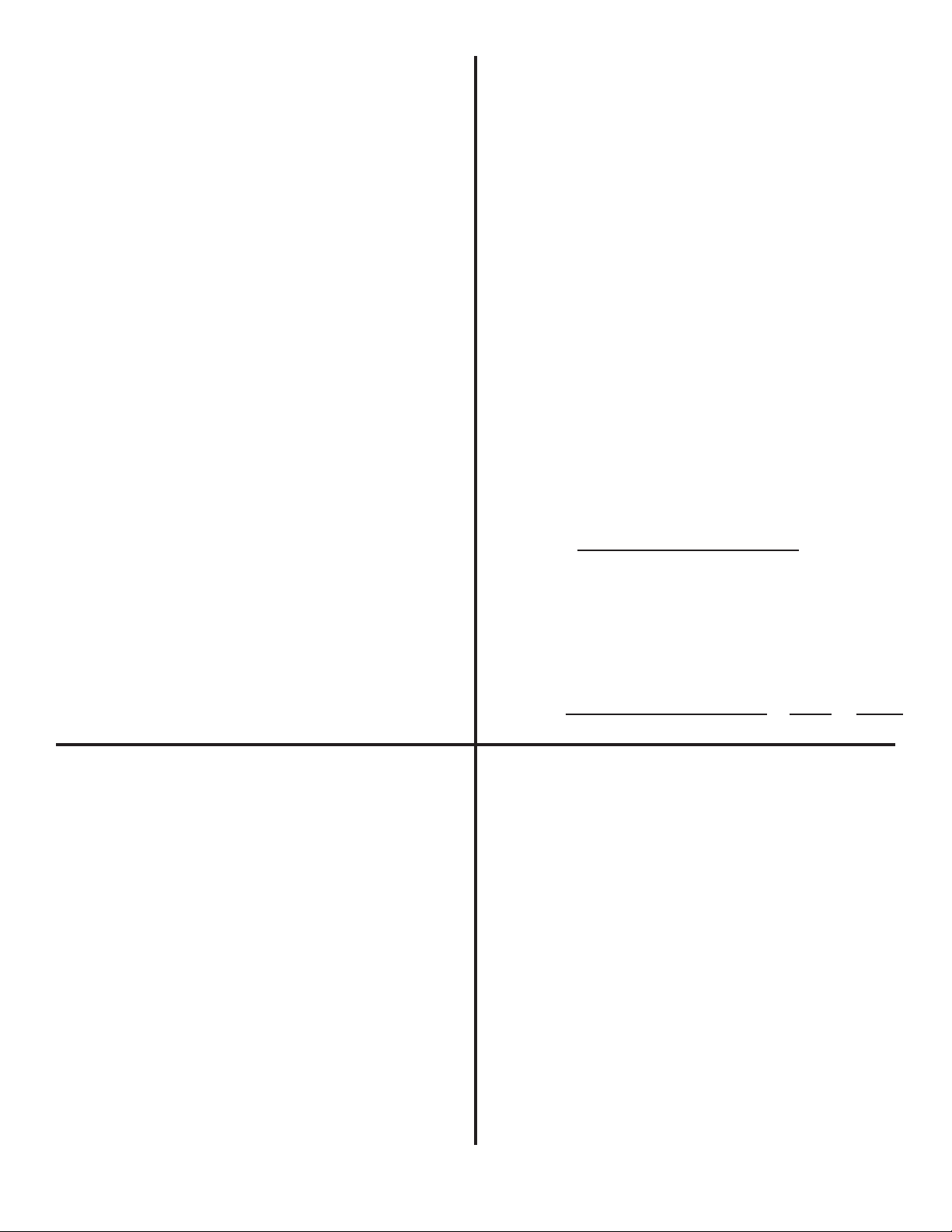
Temperature Effects
Calculating a Linear Temperature Coeffi cient
Conductivity measurement is highly dependent on temperature.
The basic rule is that higher temperatures result in greater
conductance (less resistance). Temperature effects are
expressed as the percentage of conductivity change (in S) per
°C. The conductivity value is generally referenced to 25 ºC.
The CDCN-91 has three temperature compensation options:
None
USP standards for pharmaceutical waters require that the
measurement be made without temperature compensation.
USP limits are are discussed on page 7.
Pure Water (Standard Compensation)
This selection is used for measurements of very clean water,
less than 0.2 S. Temperature effects are not linear in this
range, so the temperature coeffi cient is not easily determined.
This selection is recommended for all Resistivity applications
measuring from 5 M to 18M. This selection conforms to
ASTM standard D1125 and D5391.
Linear
This selection allows you to calculate a custom temperature
compensation value for Conductivity measurements in the
range of 0.2 S and greater (Resistivity applications measuring
less than 5 M). The procedure is outlined in the following
section.
1. Set TC Mode to NONE (see OPTIONS menu, page 7).
2. Heat a sample solution close to the maximum process
temperature. Place sensor in the sample solution and allow
several minutes for stabilization. Record the CDCN-91
temperature and conductivity values in the spaces provided:
Displayed temperature: T1 = _______ °C
Displayed conductivity: C1 = _______ °C
3. Cool the sample solution close to the minimum process
temperature. Place sensor in the sample solution allowing
several minutes for stabilization. Record displayed
temperature and conductivity values in the spaces provided:
Displayed temperature: T2 = _______ °C
Displayed conductivity: C2 = _______ °C
(A 10% change in conductivity between steps 2 and 3 is
recommended.)
4. Substitute recorded readings (steps 2 and 3) into the following
formula:
TC Slope =
(C2 x (T1 - 25)) - (C1 x (T2 - 25))
100 x (C1 - C2)
TDS Factor
Some industries need to display a conductivity value as Total
Dissolved Solids (TDS), measured in units of parts per million
(PPM) or parts per billion (PPB).
• 1 PPM is equivalent to 1 mg per liter.
• 1 PPB is equivalent to 1 g per liter.
• The CDCN-91 calculates PPM or PPB by dividing the S
value by a TDS Factor that you defi ne. The CDCN-91 will
accept a TDS factor from 0.01 to 99999.9 S per PPM (factory
preset = 2.00 S per PPM).
• TDS factors can vary widely, ranging from 1.50 to 2.50 S per
PPM. Methods for establishing a TDS factor are beyond the
scope of this manual.
NOTE: The TDS factor is always set in PPM.
TDS Factor = Conductivity (S) ÷Total dissolved solids (PPM)
PPM = Solution conductivity (S) ÷ TDS Factor
Example: A sample solution has a conductivity of 205 S @
48 °C. After cooling the solution, the conductivity was measured
at 150 S @ 23 °C (C1 = 205, T1 = 48, C2 = 150, T2 = 23).
The TC is calculated as follows:
TC Slope =
100 x (205 - 150)
(150 x (48 - 25)) - (205 x (23 - 25)) 3860 °C
5500
=
1.42%
=
Example:
• Solution conductivity = 150 S
• TDS = 80 PPM
• TDS Factor = 150 S ÷ 80 PPM = 1.88 μS per PPM.
10 Omega CDCN-91 Dual-Channel Controller
Page 13
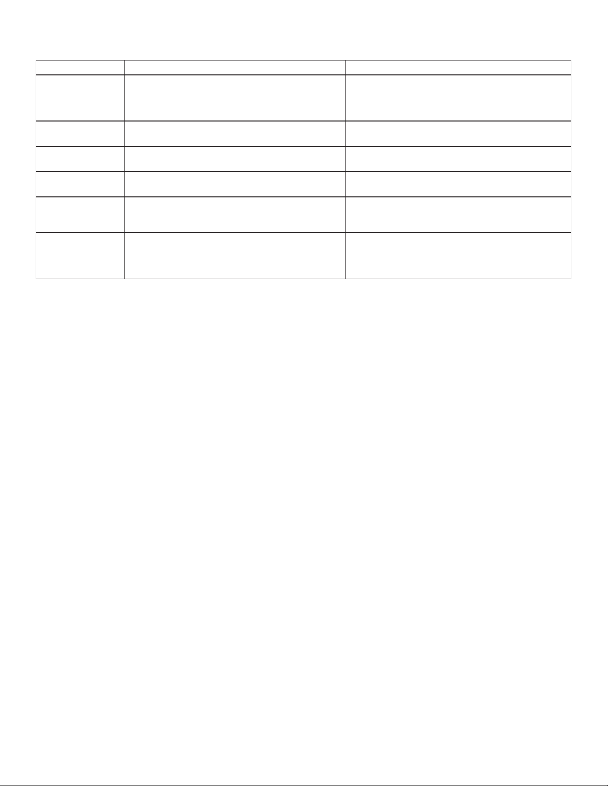
Troubleshooting
Display Condition Possible Causes Suggested Solutions
Display is over range. This may be a normal condition
- - - -
Value must be
100 or less
Value must be
more than 0
Value must be
400 or less
Reset to Factory
Calibration
Too Much Error
CHECK SENSOR
Technical Note
If a Current Loop is locked at 3.6 mA, the problem is related to the PT-1000 temperature circuit:
This occurs only if the CDCN-91 detects a resistance from the temperature sensor that is less than 250 or greater than 2800 .
• Check the sensor wiring for open/short or poor connections on white (TEMP IN) and black (ISO GND) wires.
• The temperature device in the sensor is defective.
• The transmitter is defective.
if your process operates at/near the limits of the
sensor range.
The menu item being set is a percentage value and
must be less than 100.
The menu item being set cannot be zero or a
negative value.
The Pulse Rate for Relay and Open Collector outputs
cannot be greater than 400 pulses per minute.
A value of "0" is being set into "Set: Conductivity"
menu item.
The calibration offset entered is beyond the allowable
tolerances of the instrument.
Check sensor for correct range.
Check Decimal setting in OPTIONS menu.
Check Calibrate menu settings for incompatible
SOURCE and RANGE values.
Select a value from 0 to 100.
Select a value greater than zero.
Select a pulse rate less than 400
This will remove any user calibration from the "Set
Conductivity" and "Set Temperature" items in the
Calibrate menu.
Check calibration procedure for accuracy.
Check sensor for proper operation.
Check any cable extensions for poor splices or
termination.
11Omega CDCN-91 Dual-Channel Controller
Page 14

Accessories
Surface Mount Bracket
FPM-5000-MB
RC Filter Kit (for relay use)
FP90RC (no picture available)
Liquid Tight Connector Kit
CDCN-91LTK
12 Omega CDCN-91 Dual-Channel Controller
Page 15

WARRANTY/DISCLAIMER
OMEGA ENGINEERING, INC. warrants this unit to be free of defects in materials and workmanship for a
period of 13 months from date of purchase. OMEGA’s WARRANTY adds an additional one (1) month
grace period to the normal one (1) year product warranty to cover handling and shipping time. This
ensures that OMEGA’s customers receive maximum coverage on each product.
If the unit malfunctions, it must be returned to the factory for evaluation. OMEGA’s Customer Service
Department will issue an Authorized Return (AR) number immediately upon phone or written request.
Upon examination by OMEGA, if the unit is found to be defective, it will be repaired or replaced at no
charge. OMEGA’s WARRANTY does not apply to defects resulting from any action of the purchaser,
including but not limited to mishandling, improper interfacing, operation outside of design limits,
improper repair, or unauthorized modification. This WARRANTY is VOID if the unit shows evidence of
having been tampered with or shows evidence of having been damaged as a result of excessive corrosion;
or current, heat, moisture or vibration; improper specification; misapplication; misuse or other operating
conditions outside of OMEGA’s control. Components in which wear is not warranted, include but are not
limited to contact points, fuses, and triacs.
OMEGA is pleased to offer suggestions on the use of its various products. However,
OMEGA neither assumes responsibility for any omissions or errors nor assumes liability for
any damages that result from the use of its products in accordance with information provided
by OMEGA, either verbal or written. OMEGA warrants only that the parts manufactured by the
company will be as specified and free of defects. OMEGA MAKES NO OTHER WARRANTIES OR
REPRESENTATIONS OF ANY KIND WHATSOEVER, EXPRESSED OR IMPLIED, EXCEPT THAT OF
TITLE, AND ALL IMPLIED WARRANTIES INCLUDING ANY WARRANTY OF MERCHANTABILITY
AND FITNESS FOR A PARTICULAR PURPOSE ARE HEREBY DISCLAIMED. LIMITATION OF
LIABILITY: The remedies of purchaser set forth herein are exclusive, and the total liability of
OMEGA with respect to this order, whether based on contract, warranty, negligence,
indemnification, strict liability or otherwise, shall not exceed the purchase price of the
component upon which liability is based. In no event shall OMEGA be liable for
consequential, incidental or special damages.
CONDITIONS: Equipment sold by OMEGA is not intended to be used, nor shall it be used: (1) as a “Basic
Component” under 10 CFR 21 (NRC), used in or with any nuclear installation or activity; or (2) in medical
applications or used on humans. Should any Product(s) be used in or with any nuclear installation or
activity, medical application, used on humans, or misused in any way, OMEGA assumes no responsibility
as set forth in our basic WARRANTY/D ISCLAIMER language, and, additionally, purchaser will indemnify
OMEGA and hold OMEGA harmless from any liability or damage whatsoever arising out of the use of the
Product(s) in such a manner.
RETURN REQUESTS/INQUIRIES
Direct all warranty and repair requests/inquiries to the OMEGA Customer Service Department.
BEFORE RETURNING ANY PRODUCT(S) TO OMEGA, PURCHASER MUST OBTAIN AN AUTHORIZED
RETURN (AR) NUMBER FROM OMEGA’S CUSTOMER SERVICE DEPARTMENT (IN ORDER TO AVOID
PROCESSING DELAYS). The assigned AR number should then be marked on the outside of the return
package and on any correspondence.
The purchaser is responsible for shipping charges, freight, insurance and proper packaging to prevent
breakage in transit.
FOR WARRANTY RETURNS, please have the
following information available BEFORE contacting
OMEGA:
1. Purchase Order number under which the product
was PURCHASED,
2. Model and serial number of the product under
warranty, and
3. Repair instructions and/or specific problems
relative to the product.
OMEGA’s policy is to make running changes, not model changes, whenever an improvement is possible. This affords
our customers the latest in technology and engineering.
OMEGA is a registered trademark of OMEGA ENGINEERING, INC.
© Copyright 2016 OMEGA ENGINEERING, INC. All rights reserved. This document may not be copied, photocopied,
reproduced, translated, or reduced to any electronic medium or machine-readable form, in whole or in part, without the
prior written consent of OMEGA ENGINEERING, INC.
FOR NON-WARRANTY REPAIRS,
OMEGA for current repair charges. Have
the following information available BEFORE
contacting OMEGA:
1. Purchase Order number to cover the COST
of the repair,
2. Model and serial number of the product, and
3. Repair instructions and/or specific problems
relative to the product.
consult
Page 16

Where Do I Find Everything I Need for
Process Measurement and Control?
OMEGA…Of Course!
Shop online at omega.com
TEMPERATURE
Thermocouple, RTD & Thermistor Probes, Connectors, Panels & Assemblies
Wire: Thermocouple, RTD & Thermistor
Calibrators & Ice Point References
Recorders, Controllers & Process Monitors
Infrared Pyrometers
PRESSURE, STRAIN AND FORCE
Transducers & Strain Gages
Load Cells & Pressure Gages
Displacement Transducers
Instrumentation & Accessories
FLOW/LEVEL
Rotameters, Gas Mass Flowmeters & Flow Computers
Air Velocity Indicators
Turbine/Paddlewheel Systems
Totalizers & Batch Controllers
SM
pH/CONDUCTIVITY
pH Electrodes, Testers & Accessories
Benchtop/Laboratory Meters
Controllers, Calibrators, Simulators & Pumps
Industrial pH & Conductivity Equipment
DATA ACQUISITION
Communications-Based Acquisition Systems
Data Logging Systems
Wireless Sensors, Transmitters, & Receivers
Signal Conditioners
Data Acquisition Software
HEATERS
Heating Cable
Cartridge & Strip Heaters
Immersion & Band Heaters
Flexible Heaters
Laboratory Heaters
ENVIRONMENTAL
MONITORING AND CONTROL
Metering & Control Instrumentation
Refractometers
Pumps & Tubing
Air, Soil & Water Monitors
Industrial Water & Wastewater Treatment
pH, Conductivity & Dissolved Oxygen Instruments
M3670/0916
 Loading...