

Page 1
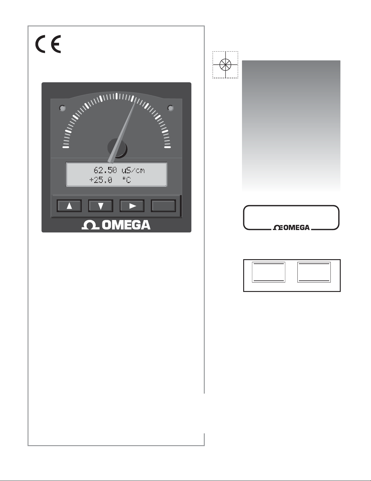
User’s Guide
IS O9002
CERTIFIED
CORPORATE QUALITY
MANCHESTER, UK
Relay 1
40
20
0
S/cm
60
Relay 2
80
100
Shop online at
ENTER
omega.com
®
www.omega.com
e-mail: [email protected]
ISO 9001
CERTIFIED
CORPORATE QUALITY
STAMFORD, CT
TM
CDCN-5800
Conductivity/Resistivity Controller
Page 2

omega.comomega.com
TM
®
OMEGAnet® Online Service Internet e-mail
www.omega.com [email protected]
Servicing North America:
USA: One Omega Drive, P.O. Box 4047
ISO 9001 Certifi ed Stamford CT 06907-0047
TEL: (203) 359-1660 FAX: (203) 359-7700
e-mail: [email protected]
Canada: 976 Bergar
Laval (Quebec) H7L 5A1
TEL: (514) 856-6928 FAX: (514) 856-6886
e-mail: [email protected]
For immediate technical or application assistance:
USA and Canada: Sales Service: 1-800-826-6342 / 1-800-TC-OMEGA
Customer Service: 1-800-622-2378 / 1-800-622-BEST
Engineering Service: 1-800-872-9436 / 1-800-USA-WHEN
TELEX: 996404 EASYLINK: 62968934 CABLE: OMEGA
Mexico: En Español: (001) 203-359-7803 e-mail: [email protected]
FAX: (001) 203-359-7807 [email protected]
Servicing Europe:
Benelux: Postbus 8034, 1180 LA Amstelveen, The Netherlands
TEL: +31 (0)20 3472121 FAX: +31 (0)20 6434643
Toll Free in Benelux: 0800 0993344
e-mail: [email protected]
Czech Republic: Rudé arm
TEL: +420 (0)59 6311899 FAX: +420 (0)59 6311114
Toll Free: 0800-1-66342 e-mail: [email protected]
France: 11, rue Jacques Cartier, 78280 Guyancourt, France
TEL: +33 (0)1 61 37 29 00 FAX: +33 (0)1 30 57 54 27
Toll Free in France: 0800 466 342
e-mail: [email protected]
Germany/Austria: Daimlerstrasse 26, D-75392 Deckenpfronn, Germany
TEL: +49 (0)7056 9398-0 FAX: +49 (0)7056 9398-29
Toll Free in Germany: 0800 639 7678
e-mail: [email protected]
United Kingdom: One Omega Drive, River Bend Technology Centre
ISO 9002 Certifi ed Northbank, Irlam, Manchester
M44 5BD United Kingdom
TEL: +44 (0)161 777 6611 FAX: +44 (0)161 777 6622
Toll Free in United Kingdom: 0800-488-48
e-mail: [email protected]
.
dy 1868, 733 01 Karvin. 8
®
®
®
It is the policy of OMEGA to comply with all worldwide safety and EMC/EMI regulations that apply.
OMEGA is constantly pursuing certifi cation of its products to the European New Approach Directives.
OMEGA will add the CE mark to every appropriate device upon certifi cation.
The information contained in this document is believed to be correct, but OMEGA Engineering, Inc. accepts
no liability for any errors it contains, and reserves the right to alter specifi cations without notice.
WARNING: These products are not designed for use in, and should not be used for, patient-connected applications.
Page 3
Shld
Signal IN
Temp. IN
Iso. Gnd
-
+
Red
White
Black
Silver (Shld)
Cell Constant
Range (mS):
0.01 0.055 - 100 (10 kΩ -18 MΩ)
0.1 1 - 1,000 μS
1.0 10 - 10,000 μS
10.0 100 - 200,000 μS
20.0 200 - 400,000 μS
4-20
mA
CDCN-5800
Terminals
= Double Insulated
= DC or AC power
OMEGA CDCN-5800 Conductivity/Resistivity Monitor Instructions
CAUTION!
• Refer to instruction manual for more details.
• Remove power to unit before wiring input and output connections.
• Follow instructions carefully to avoid personal injury.
Contents
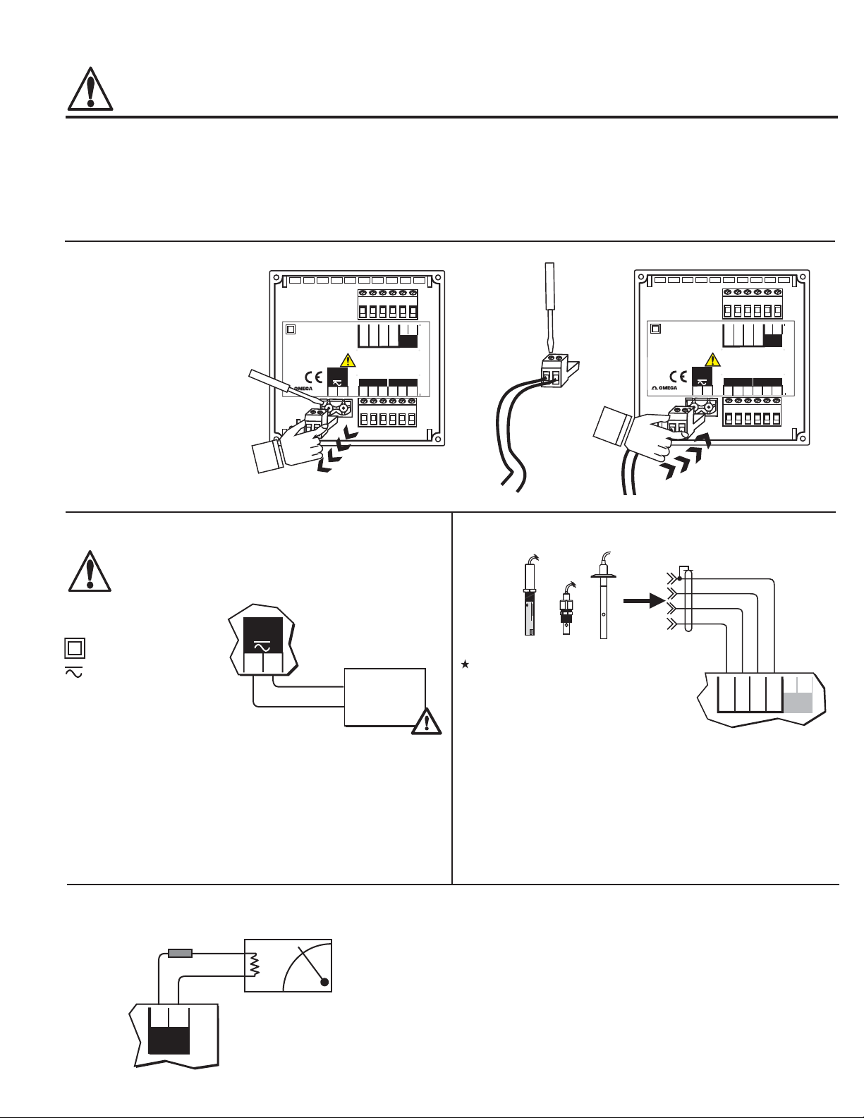
1. Power Connections
2. Compatible Sensor Wiring
3. 4 - 20 mA Current Output Connections
4. Relay Connections
5. Relay Operation
6. Menu Functions
7. Parts Per Million (PPM) Factor
Remove terminal blocks
1.
for easy wiring
8. Temperature Coeffi cient
9. Parts and Accessories
10. Specifi cations
11. Quick Reference Menu Parameters
12. Troubleshooting
13. Maintenance
2.
3.
+
-
Shld
Red wire
Black wire
Silver wire
White wire
4-20
Iso. Gnd
Tem p. I N
Signal IN
mA
1 2
Model CDCN-5800
Model CDCN-5800
1 2
12-24 V
10 W
+
Relay 1Relay 2
Patent No. D 376,328
NC
C
NO
-
Patent No. 5,708,363 Conductivity
NO
C
NC
1. Power Connections 2. Compatible Sensor Wiring
CAUTION!
Never connect 110 VAC or 220 VAC to rear power
terminals. High voltage AC will damage instrument and
void warranty.
12-24 V
10 W
+
CDCN-5800
Terminals
-
External power
supply
-
12 - 24 VDC
OR
12 - 24 VAC
+
1 2
12-24 V
10 W
+
+
-
Shld
Red wire
Black wire
Silver wire
White wire
4-20
Iso. Gnd
Tem p. I N
Signal IN
mA
Relay 1Relay 2
Patent No. D 376,328
NC
C
NO
-
Patent No. 5,708,363 Conductivity
NO
C
NC
Technical Notes:
• To reduce the possibility of noise interference, isolate AC
power lines from signal lines.
• Maximum 4-20 mA loop impedance (sec. 3) is affected by the
supply voltage.
3. 4-20 mA Current Output Connections
Fuse**
1/8A
+
-
+
-
4-20
mA
CDCN-5800
Conductivity
Terminals
4 - 20 mA*
*
Technical Notes:
• Resistivity measurements within the 10 M to 18 M range
must be performed in solution temperatures from 20°C to
100°C.
• Use three conductor shielded cable for cable extensions up to
30 m (100 ft) max.
• Cable shield MUST be maintained through cable splice.
To isolate output and prevent ground loop problems:
1. Use monitor device with isolated inputs, or
2. Use separate DC supply for 5800CR and monitor device, or
3. Power 5800CR with 12 - 24 VAC step down transformer
Technical Notes:
** 1/8A fuse recommended (customer supplied)
* 4-20 mA output is internally powered (non-isolated),
maximum loop impedance 350 with a 12 V instrument supply
voltage, 950 with a 24 V instrument supply voltage.
Page 4
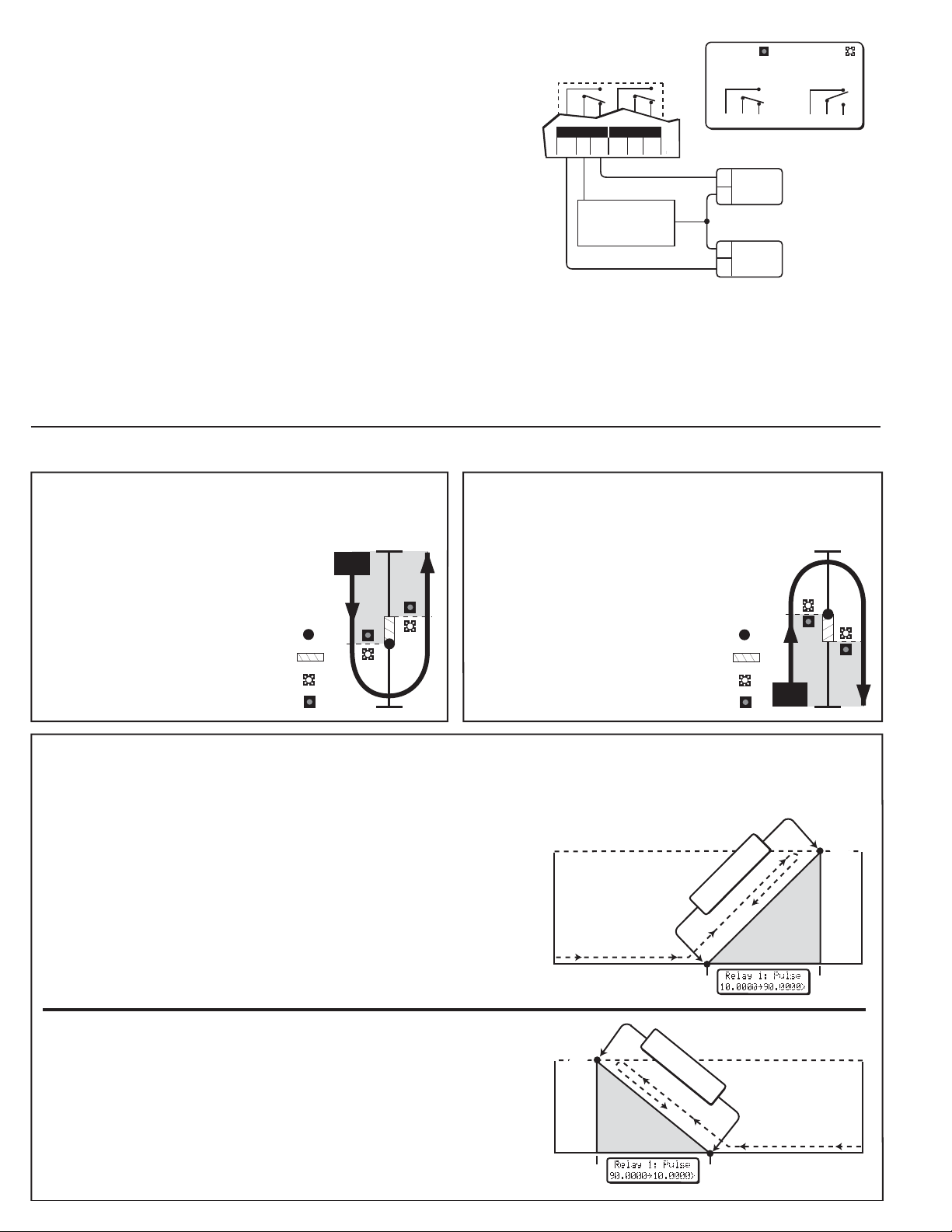
A. LOW alarm mode
The relay is energized when the solution conductivity (μS) drops
below the setpoint, and is de-energized when the solution conductivity
rises above the setpoint plus hysteresis
(sec. 6.2F, 6.2G).
B. HIGH alarm mode
The relay is energized when the solution conductivity (μS) rises above
the setpoint and is de-engergized when the solution conductivity
falls below the setpoint plus hysteresis
(sec. 6.2F, 6.2G).
μ
S
μ
S
Low setpoint=
Adjustable hysteresis=
Relay energized=
Relay de-energized=
High setpoint=
Adjustable hysteresis=
Relay energized=
Relay de-energized=
C. Proportional PULSE mode
The proportional pulse relay configuration is primarily designed for metering pump control. The operator is prompted to enter a minimum and
maximum conductivity setpoint and maximum pulse rate for the assigned relay (sec. 6.2H, 6.2I). Relay pulse width is fixed at 130 ms. Refer to the
operation examples below.
• Metering pump chemical addition (dry contact activation type required)
Example 1 (right):
As the process conductivity (μS) rises above the minimum pulse setpoint (10 μS) the
relay begins pulsing; triggering the metering pump for deionized water addition.
As the process conductivity continues to rise, pulsing accelerates proportionally until
the maximum programmed pulse rate of 300 pulses/minute and setpoint (90 μS)
are reached, forcing the process conductivity back down to intended
levels (e.g. ≤10 μS).
Example 2 (right):
As the process conductivity falls below the minimum pulse setpoint (90 μS) the relay
begins pulsing; triggering the metering pump for chemical addition. As the process
conductivity continues to decrease, pulsing accelerates proportionally until the
maximum programmed pulse rate of 300 pulses/minute and setpoint (10 μS) are
reached, forcing the process conductivity back up to intended levels (e.g. 90 μS).
Relay 1 or
Relay 2
10
μS
90
μS
0 pulses
μ
S
Relay 1 or
Relay 2
90
μS
10
μS
μ
S
300 pulses
300 pulses
0 pulses
Relay 1 Rate
:
300 Pulses
/min
>
Relay 1 Rate:
300 Pulses/min >
4. Relay Connections
Two internal relay contact sets (COM, NO, and NC) may be used
for external device control. Front panel LED annunciators indicate
the activation status of each relay. Each relay can control up to
two devices simultaneously, as shown. Relay operation modes
include Low alarm, High alarm, and Proportional Pulse (sec. 5).
Common device connections include:
• Pulse mode - metering pump control
• Pulse mode - solenoid valve control
• Low or High mode - warning lamps
• Low or High mode - bells or sirens
• Low or High mode - external heavy-duty relay
CDCN-5800
Terminals
NO
C
NC
+
External AC/DC
Relay 1Relay 2
NO
power
Relay
De-energized
C
NO
NC
C
NC
Device
+
A
-
Relay
Energized
C
NO
NC
-
-
Device
B
+
Wiring Example Right
Device A IS powered when relay 2 is de-energized (front panel
LED "off"). Power is discontinued when the relay 2 setpoint is
reached (front panel LED "on"). Device B IS NOT powered when
the relay 2 is de-energized. Power is applied after the relay 2
setpoint is reached.
5. Relay Operation
Technical Notes:
• Maximum relay contact ratings: 5 A @ 30 VDC, 5 A @ 125 VAC,
or 3 A @ 250 VAC
• An external heavy-duty relay must be used for devices with
surge currents or operating currents that exceed the above specifi -
cations.
Page 5
OPTIONS
CALIBRATE
VIEW
2s 5s
Press &
hold for
access:
ENTER
BA
D
E
C
AL
AR
M
1
AL
AR
M 2
0
100
AL
AR
M 1
ALAR
M
2
0-2/0-4,
0-6/0-8,
0-10/0-100
0
10
S/cm
S/cm
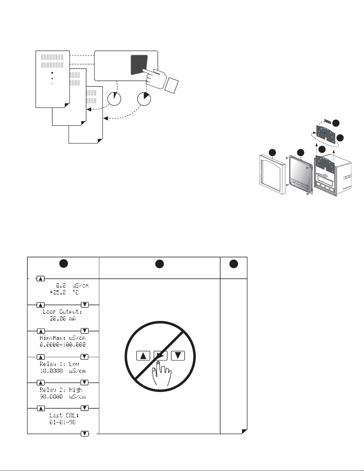
6. Menu Functions
To access either CALIBRATE or OPTIONS menus, press and hold
the ENTER key as illustrated below:
Menus:
• VIEW menu (sec. 6.1): The VIEW menu is displayed during
standard operation. The operator can navigate freely through
the menu by pressing either UP or DOWN arrow keys.
• CALIBRATE Menu (sec. 6.2): The CALIBRATE menu contains all critical display setup and output parameters. A simple
security code feature prevents unauthorized tampering. The
operator is required to enter a simple access code for menu
access. The same code also unlocks OPTIONS menus.
• OPTIONS Menu (sec. 6.4): The OPTIONS menu contains
setup and display features that are seldom accessed for minor
display or output adjustments.
• Reversible Dials
The 5800CR includes
a dial kit with 6
reversible dial faces
and units decals
(factory installed
dial: 0 - 100). See
dial kit for additional
information.
6.1 VIEW Menu
↓F
A.
B.
C.
D.
E.
F.
1
Choose:
Cond./temp.
Loop output
Range
Relay 1
Relay 2
Last calibration
↑A
2
Change:
3
Save:
Menu Displays A - F:
(Factory default displays shown in menu
column 1)
A. Active display of conductivity, resistivity, or
PPM (TDS) and Temperature in degrees
Celsius (°C) or Fahrenheit (°F).
B. Loop output display: shows the loop cur-
rent output level.
C. Range display: shows the programmed
min and max meter dial range (sec. 6.2D).
D. Relay 1 display: shows the programmed
operation mode and setpoint for relay 1
(sec. 6.2F).
E. Relay 2 display: shows the programmed
operation mode and setpoint for relay 2
(sec. 6.2F).
F. Last calibration: shows a user defi ned
setup date for maintenance records. This
feature is not an internal timer or calender.
Page 6
Choose:
1
Change:
2
Save:
3
Mode Range
Relay
quick
press
To return to
VIEW:
quick
press
To restore original value:
Wet Calibration System calibration
Measured units
Meter Min→Max
Units
Last calibration
Optional
Press <ENTER> key to access
WET CAL procedure (sec. 6.3);
"Please Wait" briefly displays
Cell
type
Cell
value
Sensor
Range
PPM Factor
Factory default: 2.00
Shown only with PPM units selected above
Relay Low or High Mode Selected
Relay Pulse Mode Selected, Step F
Press keys in sequence
will appear during code entry.
to continue,
Mode Setpoint
Relay
Hysteresis
Relay
Pulse rate
Relay
ENTER
↓J
↑A
A.
B.
C.
D.
E.
F.
G.
H.
I.
J.
"SAVING"
briefly
displays
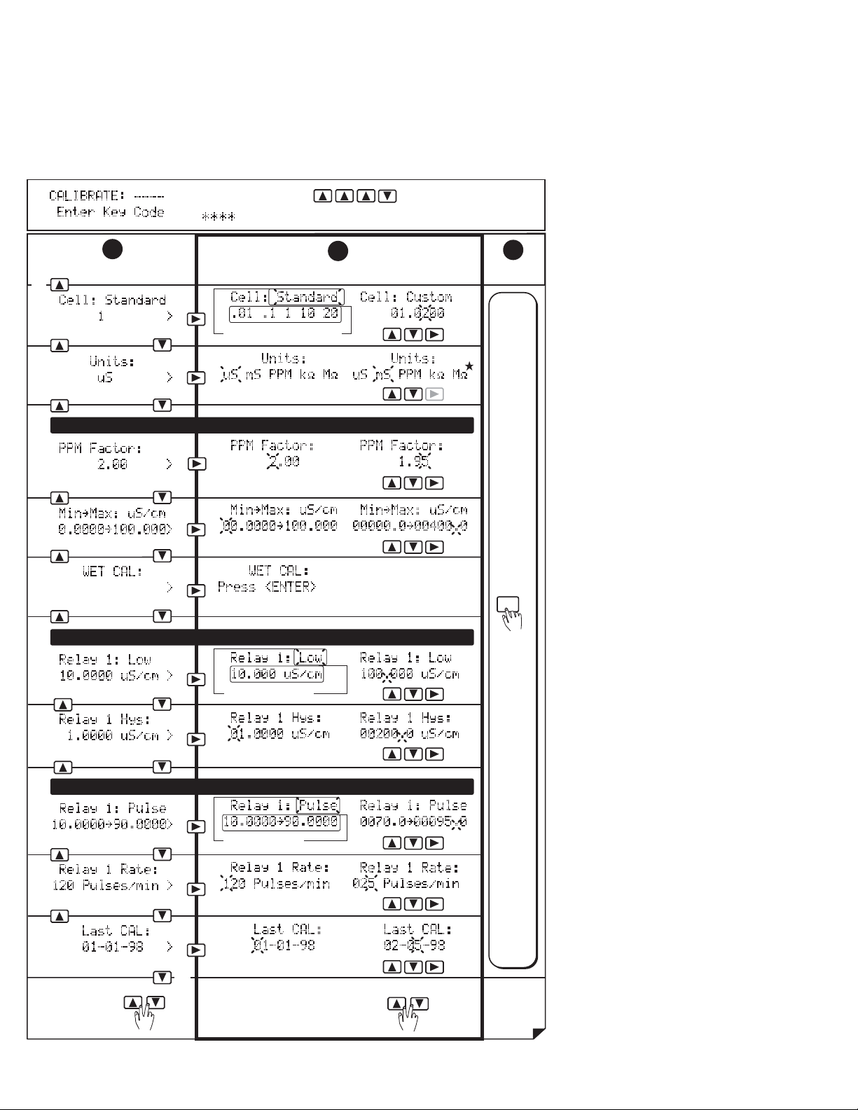
6.2 CALIBRATE Menu
Requirements
System calibration (Step E, WET CAL) is required for fi rst-time system setup or periodic sen-
sor verifi cation. System calibration can be performed with with a solution of know conductiv-
ity and an accurate thermometer, or with fi xed resistors. Refer to the WET CAL procedure
(sec. 6.3) for calibration details.
Menu Settings A - J:
(Factory default displays shown in menu
column 1)
A. Selects cell type and cell value:
• Standard cells: 0.01, 0.1, 1.0, 10.0,
or 20.0
• Custom (certifi ed) cells: 00.0000 -
999999.
See section 2 for recommended cell con-
stant and operation range
B. Selects displayed conductivity units;
Solution temperatures limited from 20°C
to 100°C for measurements from
10 M to 18 M.
C. Sets PPM factor when PPM display units
are selected (step B), 0.01 - 9.99. Refer
to section 7 for feature explanation.
D. Sets Min Max meter dial range (factory
installed dial, 0 - 100). Contact factory
for custom dial confi gurations. Does not
affect 4 to 20 mA output
E. Selects WET CAL procedure for fi rst time
system setup or periodic system recalibration (sec. 6.3).
Menu items F - I repeat for relay 2 setup.
F. Sets relay operation mode Low or High,
and setpoint, 00.0000 - 999999. units
(sec. 5).
G. Sets relay hysteresis, 00.0000 - 999999.
units (sec. 5). Set to zero to disable
feature
H. Sets relay minimum and maximum pulse
setpoint, 00.0000 - 999999. units (sec 5).
I. Sets relay pulse rate, 000 - 300 pulses/
minute (sec. 5).
J. Sets user defi ned setup date for
maintenance records. This feature is not
an internal timer or calendar
Page 7
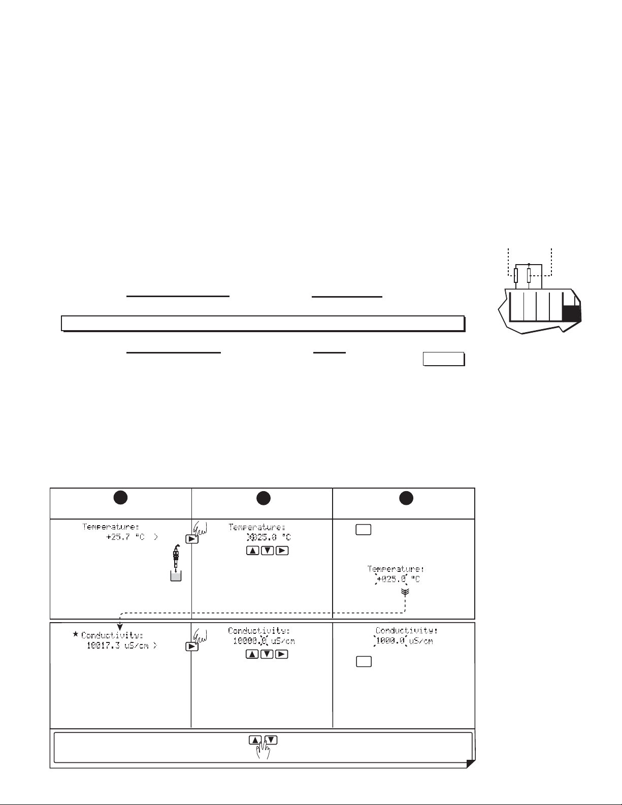
Display:
1
To Change:
2
To Accept:
3
A) Solution cal.: place sensor and
thermometer into standard solution then
press right arrow key.
B) Resistor verification: press right
arrow key.
A) Solution cal.: allow approx. 3 minutes for
stabilization, then enter solution temperature*
B) Resistor verification: enter 25.0 C on
display.
Enter known solution conductivity or calculated
conductivity.
Optional: enter zero to reset factory calibration
(zero MUST be re-entered if currently displayed
to reset factory calibration).
Measured conductivity shown after
temperature calibration
Press to accept conductivity calibration;
display returns to CALIBRATE MENU in 3
seconds (sec. 6.2E)
Press to accept temperature
calibration.
ENTER
ENTER
quick
press
To exit WET CAL at any time without
saving changes:
Resistance = Cell ; e.g. 0.1 = 5,000Ω or 5 kΩ
Desired conductivity (Siemens*) 0.000020 (Siemens*)
*Conversion: 1 μS = 1 X 10
-6
Siemens or 0.000001 Siemens
Conductivity = Sensor cell ; e.g. 0.1 = 0.000001 Siemens*
Simulation resistance (Ohms) 100,000 or 1 μS/cm
6.3 WET CAL Procedure
Requirements
Electronic calibration is performed to exacting standards by OMEGA. System calibration will reduce errors which may be caused by
sensor wire lengths longer than the standard fi fteen feet length. Wire lengths of 100 feet are acceptable; cable shield must be maintained
through cable splice. Calibration may be done by known solution value (A), or by resistance simulation (B).
A) Calibration with NIST Traceable Solutions:
When using calibration standards traceable to the National Institute of Standards and Technology (NIST), care must be taken to ensure
the sensor and test solution are at the solution temperature specifi ed on the test solution label. Care must be taken to prevent con-
tamination of the calibration solution. It is recommended to thoroughly rinse the sensor in a small amount of test solution (then discard)
before placing in any test solution for calibration purposes. The two step WET CAL process fi rst allows for verifi cation or calibration of
temperature, followed by verifi cation or calibration of either conductivity, resistivity, or PPM (TDS) using a known process solution.
B) Optional Verifi cation with Precision Resistors:
The use of precision resistors (±0.1%) connected to the rear "Temp In", "Signal IN", and "Iso Gnd" terminals in place of the OMEGA
sensor, will yield quick and accurate electronic instrument calibration. The WET CAL procedure allows for verifi cation or calibration of
temperature, followed by conductivity, resistivity, or PPM (TDS) utilizing precision resistors. Calibration is completed as follows:
1) Select a standard cell constant based on desired range of operation (sec. 10, Fig. 1).
2) Place a 1096 TC resistor between "Temp IN" and "Iso. Gnd" terminals as shown. Note: Temperature
Simulation
resistor
simulation errors can adversely effect calibration: 3.85 ohms = 1°C error.
3) Calculate the required simulation resistor that represents a value within the selected cell range
(sec. 10, Fig. 1). The formula for determining the required simulation resistance is:
4) Place the calculated simulation resistance between the "Signal IN" and "Iso Gnd" terminals as shown.
5) Perfor WET CAL Procedure below, setting temperature to 25.0 °C and conductivity to the calculated value, step 3.
WET CAL Procedure (Solution Calibration Illustrated below)
Temp. IN
Signal IN
TC
resistor
CDCN-5800
Terminals
Shld
Iso. Gnd
+
4mA
*IMPORTANT:
Always match test solution
manufacturer's temperature
recommendation.
Conductivity units are displayed as selected in the
CALIBRATE menu (sec. 6.2B).
Resistivity units are displayed
when k or M ranges are
selected (sec. 6.2B).
Page 8
Choose:
1
Change:
2
Save:
3
quick
press
To return to
VIEW:
quick
press
To restore original value:
Contrast Low -- -- -- -- -- High
Loop output
20 mA adjust
Temp. display
C or F
Conductivity Display decimal
Temp. comp %
Factory default: 2.00
Press keys in sequence
will appear during code entry.
to continue,
0s 4s 8s
Averaging
Loop output 4 mA adjust
Loop output Set 4 mA
Loop output Set 20 mA
ENTER
"SAVING"
briefly
displays
↓I
↑A
A.
B.
C.
D.
E.
F.
G.
H.
I.
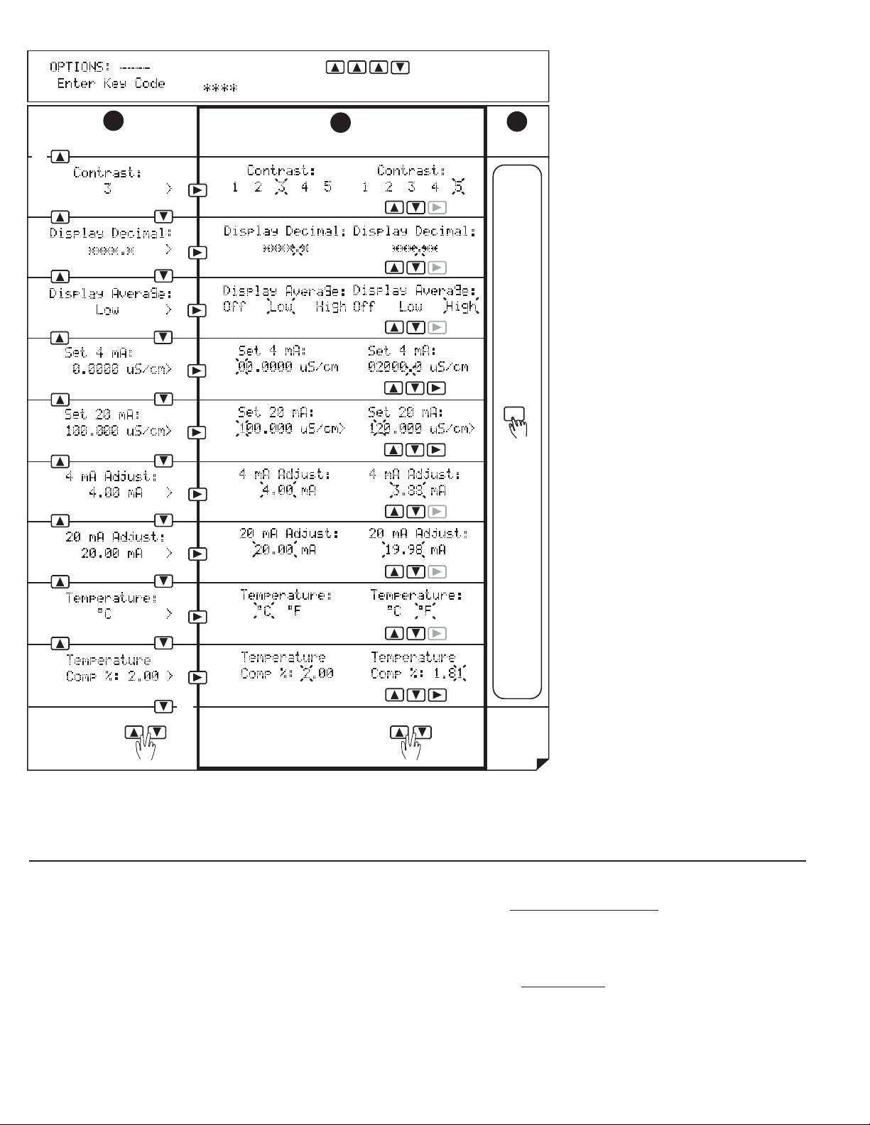
6.4 OPTIONS Menu
Menu Settings A - I:
(Factory default displays shown in menu
column 1)
A. Selects LCD display contrast: 5 levels
B. Selects display decimal:
. to
*****
C . Selects LCD display averaging:
Off = 0 seconds, Low= 4 seconds, High=
8 seconds (also effects 4 - 20 mA output)
D. Sets 4 mA output setpoint. 4 mA and
20 mA setpoints are reversible.
E. Sets 20 mA output setpoint. 20 mA and
4 mA setpoints are reversible.
F. Sets 4 mA current output: 3.0 to 5.0 mA
(overrides 4.00 mA factory calibration)
G. Sets 20 mA current output: 19 to 21 mA
(overrides 20.00 mA factory calibration)
H. Selects temperature display: °C or °F
Recalibration is not required when switch-
ing
from Celsius to Fahrenheit.
I. Selects temperature compensation %
(coeffi cient), see section 8 for feature
explanation.
***.**
7. Parts Per Million (PPM) Factor
This feature is only applicable when PPM display units are selected (sec. 6.2B).
The 5800CR is capable of displaying total dissolved solids (TDS)
in parts per million (PPM) units. This is done by dividing the actual
solution conductivity in S by the programmed parts per million
factor (sec. 6.2C).
TDS (PPM) = Solution conductivity (S)
PPM Factor
Example:
• PPM Factor = 2.00 (factory default)
• Solution conductivity = 400 S
• TDS (PPM) = 400 S = 200 PPM on the display
2.00 PPM Factor
Page 9
gasket
Rear C
4-s
RELAY 1
RELAY 2
RELAY 3
RELAY 4
N/C
N/O
COM
N/C
N/O
COM
N/C
N/O
COM
N/C
N/O
COM
RELAY 3,4
OPEN
COLL 3,4
- OPEN COLL 4
+
OPEN COLL 4
-
OPEN COLL 3
+
OPEN COLL 3
-
LOOP 2
+
LOOP 2
-
LOOP 3
+
LOOP 3
-
LOOP 1
+
LOOP 1
SHLD
ISO GND
TEMP 1
SGNL 1
SHLD
ISO GND
TEMP 2
SGNL 2
POWER
OUTPUT OPTION
®
L
N
-
+
ca
Liquid Tight
Connector
The programmable PPM Factor is adjustable from 0.01 to 9.99
(factory default = 2.00). You can determine the best PPM Factor
for your process solution if you know the solution's conductivity
(S) and the
percent of total dissolved solids (PPM), see example below:
PPM Factor = Solution conductivity (S)
Total dissolved solids (PPM)
8. Temperature Coeffi cient (Temp. Comp. %)
Conductivity measurement is highly dependent on temperature.
Temperature dependence is usually expressed as the relative
change per °C, commonly known as percent/°C change from 25
°C, or slope of the solution.
Slopes can very signifi cantly depending on process solution type.
The factory default temperature compensation factor is 2.00%/°C.
This setting satisfi es many general applications. Your process
solution may require adjustment for maximum accuracy. The following procedure can be used to determine the optimum temperature compensation factor for your process. This procedure can be
used when published references are not available.
NOTE:
Do not use this procedure for solutions from 0.055 S to 0.1
S (10 M to 18 M). An internal pure water curve is used for
these ranges. The factory default setting of 2.00%/°C should
be used.
Equipment Required
• CDCN-5800 monitor and CDCE-90-X series conductivity
sensor
• Process solution samples (2)
• Temperature source
Procedure
1. Disable the temperature comp % factor by entering 0.00
(sec. 6.4I).
2. Heat the sample solution close to the maximum process
temperature. Place sensor in the sample solution (allow
several minutes for stabilization). Access the VIEW menu (sec.
6.1A) and record the displayed temperature and conductivity
values in the spaces provided below:
Example:
• Solution conductivity = 400 S
• TDS = 200 PPM (mg/L)
• PPM Factor = 400 S = 2.00
200 PPM
3. Cool the sample solution close to the minimum process
temperature. Place sensor in the sample solution (allow
several minutes for stabilization). Record displayed
temperature and conductivity values in the spaces provided
below:
Sample Solution (Step 3)
Displayed temperature:
T2= °C
Displayed conductivity:
C2=
A 10% change in conductivity between steps 2 and 3 is required
for optimum performance. If necessary, increase maximum (step
2) and reduce minimum (step 3) sample temperatures. This will
result in a larger change in conductivity between steps.
4. Substitute recorded readings (steps 2 and 3) into the following
formula:
TC Slope = 100 x (C1 - C2)
(C2 x (T1 - 25)) - (C1 x (T2 - 25))
Example:
A sample solution has a conductivity of 205 S @ 48°C. After
cooling the solution, the conductivity was measured at 150 S @
23°C. Therefore: C1 = 205, T1 = 48, C2 = 150, T2 = 23.
The TC is calculated as follows:
Sample Solution (Step 2)
Displayed temperature:
T1= °C
Displayed conductivity:
C1=
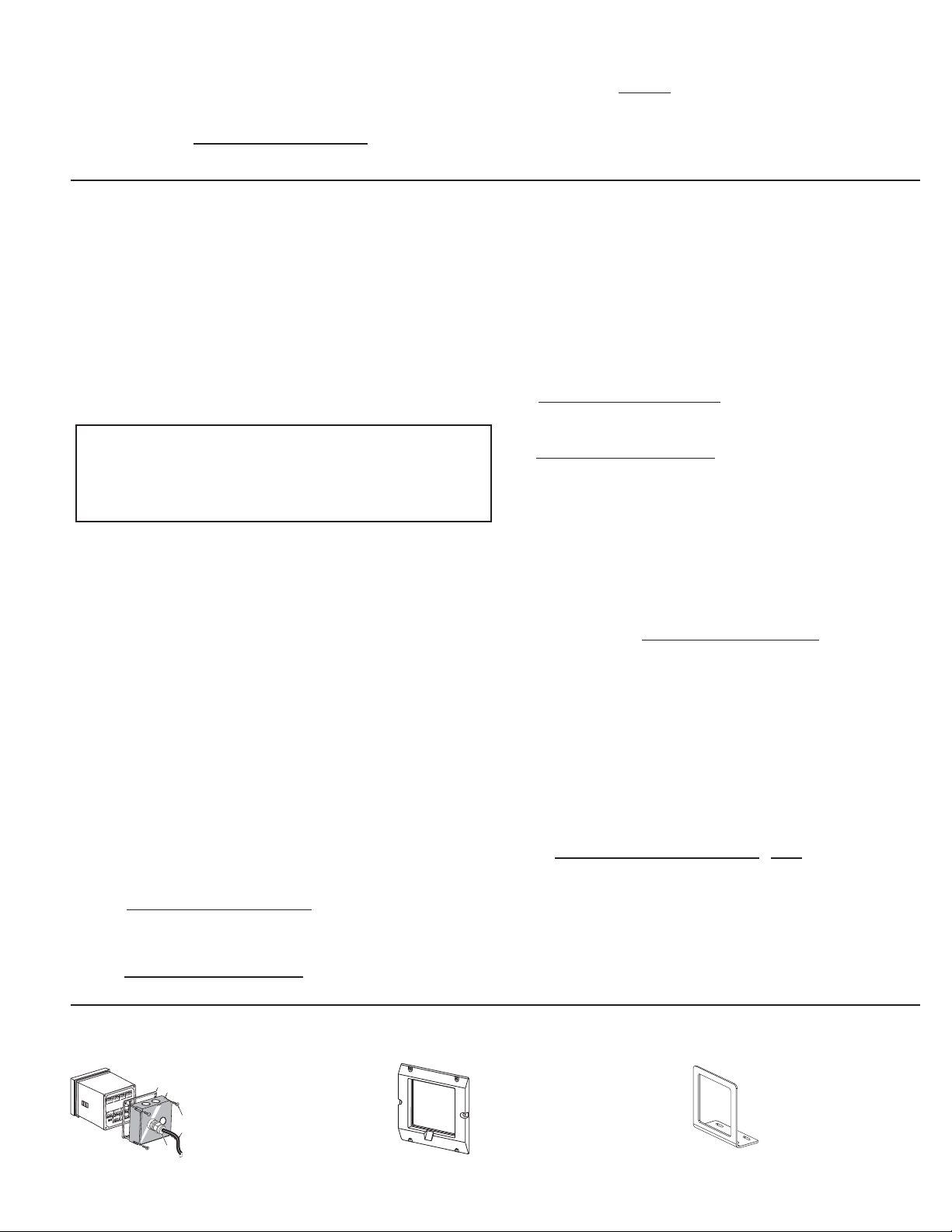
9. Parts and Accessories
Splashproof rear cover
FPM-5000-SBCK
TC Slope =
100 x (205 - 150) = 5500 = 1.42%/°C
(150 x (48 - 25)) - (205 x (23 - 25)) 3860
5 x 5 inch adapter plate
for OMEGA retrofi t
Optional surface mount
bracket FP-5000-MB
FPM-5000-RAK
Page 10
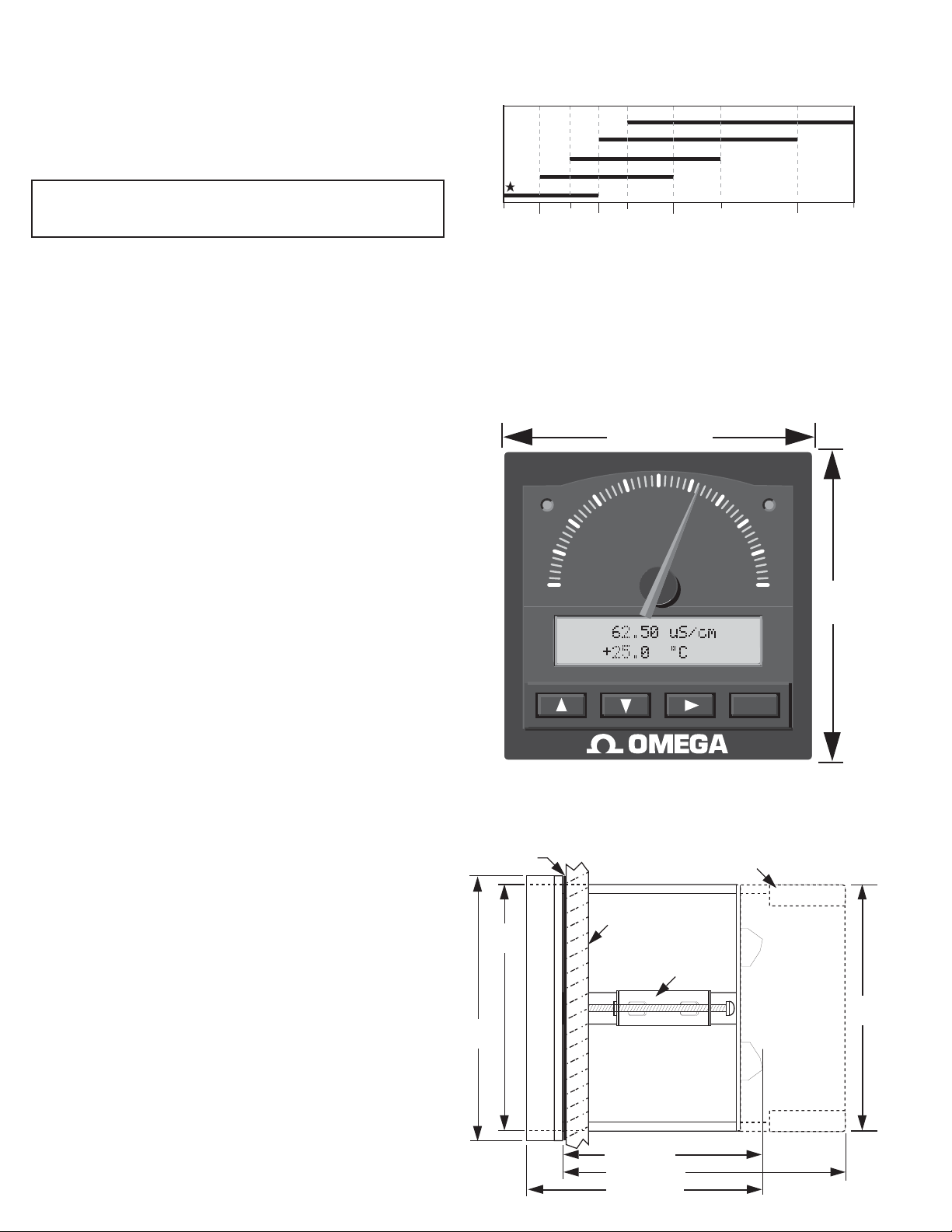
96 mm
(3.8 in.)
Front View
96 mm (3.8 in.)
Relay 2
Relay 1
ENTER
0
20
40
60
80
100
S/cm
10. Specifi cations
General
Compatible sensors: OMEGA CDCE-90-X Standard and Certifi ed
Series Sensors (Figure 1)
Accuracy: ±2% of reading
Input range: 0.055 to 400,000 S (10 k to 18 M),
optically isolated
Resistivity measurements from 10 MΩ to 18 MΩ (or
conductivity range 0.055 S to 0.1 S) must be performed in
solution temperatures from 20°C to 100°C.
Enclosure:
• NEMA 4X/IP65 front
• Dimensions: ¼ DIN, 96 x 96 x 88 mm (3.8 x 3.8 x 3.5 in.)
• Case materials: ABS plastic
• Keypad material: Sealed 4-key silicone rubber
• Weight: 500 g (18 oz.)
Ultra-
Pure
Pure
CDCE-90-01
CDCE-90-001
Sensor Models
0.055
(18 MΩ)
1
Figure 1
OMEGA Conductivity Sensor Ranges
Rinse
CDCE-90-1
10 200
(10 kΩ)
CDCE-90-20
CDCE-90-10
100
1,000
Conductivity Range (μS)
10,000
200,000
400,000
Display:
• Type: Microprocessor controlled air-core meter movement and
backlit alphanumeric 2 x 16 LCD
• Update rate: <2s
• Contrast: User selected
• Relay annunciators: 2 LEDs
• Displayed units: S, mS, k, M, PPM
Environmental
Operating temp.: -10 to 55°C (14 to 131°F), 50°C (122°F)
max. with optional rear cover
Storage temp.: -15 to 80°C (5 to 176°F)
Relative humidity: 0 to 95%, non-condensing
Altitude: 4000 m max.
Pollution degree: 2
Electrical
Power requirements:
• 12 to 24 VDC or 12 to 24 VAC, unregulated, 50-60 Hz,
10 W max.
Temperature input:
• PT1000, 0 to 100°C (32 to 212°F), optically isolated
Relay outputs (2 sets):
• Mechanical SPDT contacts
• Max. voltage rating: 5 A @ 30 VDC, 5 A @ 125 VAC, or
3 A @ 250 VAC, (power factor = 1.0)
• Hysteresis: User adjustable
Current output:
• 4 to 20 mA, non-isolated, internally powered, fully adjustable and
reversible
• Update rate: <2s
• Max loop impedance: 350 with a 12 V instrument supply
voltage, 950 with a 24 V instrument supply voltage
• Accuracy ±0.1% of max range
Agency Approvals
• CE
• Manufactured under ISO 9001 and ISO 14001
Dimensions:
Panel
Gasket
91 mm
(3.6 in.)
96 mm
(3.8 in.)
Optional Splashproof Rear Cover
Mounting Panel
Mounting Clamp (2 ea.)
88 mm
(3.5 in.)
Side View
76 mm (3 in.)
96 mm (3.8 in.)
88 mm (3.5 in.)
Page 11
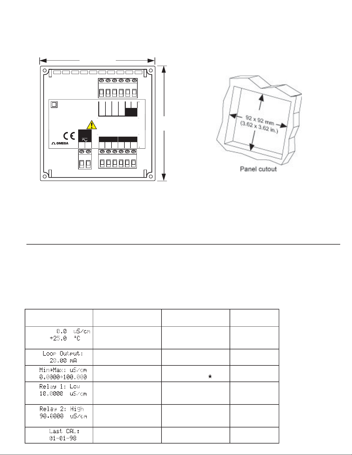
Menu
Parameters
Factory
Default
Range
Display
Description
• Process conductivity
• Process temperature
Current loop
output
Min → Max meter
dial range
• Relay 1 mode
• Relay 1 setpoint
• Relay 2 mode
• Relay 2 setpoint
Last calibration
date
• 0.055 - 400,000 mS
(10 kΩ - 18 MΩ)
• Process temperature
3 - 21 mA
0.055 - 400,000 mS
(10 kΩ - 18 MΩ )
Low, High, or Pulse,
0.055 - 400,000 mS
(10 kΩ - 18 MΩ)
Low, High, or Pulse,
0.055 - 400,000 mS
(10 kΩ - 18 MΩ)
00 - 00 - 00 -
39 - 39 - 99
n/a
n/a
n/a
0.0000 -
100.000 μS/cm
Low
10.0000 μS/cm
High
90.0000 μS/cm
01 - 01- 98
A.
B.
C.
D.
E.
F.
88 mm
(3.5 in.)
88 mm (3.5 in.)
Rear View
4-20
mA
-
+
NC
C
NO
NC
C
NO
-
+
Relay 1 Relay 2
12-24 V
10 W
Patent No. D 376,328
Patent No. 5,708,363
Conductivity
Signal IN
Red wire
Iso. Gnd
Black wire
Shld
Silver wire
Temp. IN
White wire
Model CDCN-5800
Dimensions:
11. Quick Reference Menu Parameters
11.1 VIEW Menu Setup Parameters (sec. 6.1)
Resistivity measurements
from 10 MΩ to 18 MΩ
(or conductivity from
0.055 S to 0.1 S)
must be performed in
solution temperatures
from 20°C to 100°C.
Page 12
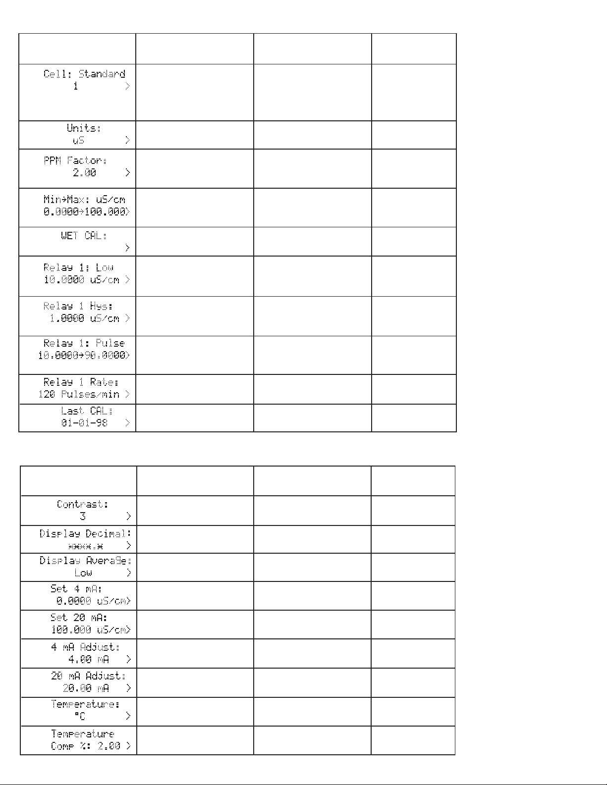
Menu
Parameters
Factory
Default
Range
Display
Description
Display
contrast
Display
decimal
Display
averaging
4 mA
setpoint
20 mA
setpoint
4 mA
adjust
20 mA
adjust
Temperature
display
Temperature comp.
percentage
0 - 5
*.**** -
*****
.
Off= 0 sec., Low= 4 sec.,
High= 8 sec.
00.0000 -
999999.
00.0000 -
999999.
3.0 - 5.0 mA
19 - 21 mA
Celsius or
Fahrenheit
0.00 % -
9.99 %
3
****.*
Low= 4 sec.
00.0000
μS/cm
100.000
μS/cm
4.00 mA
20.00 mA
°C
2.00 %
A.
B.
C.
D.
E.
F.
G.
H.
I.
Menu
Parameters
Factory
Default
Range
Display
Description
Sensor type:
and cell constant
Process
units
Total dissolved solids
(PPM) factor
Min → max
meter dial range
System Calibration
Procedure
• Relay 1 mode
• Relay 1 setpoint
Relay 1
hysteresis
• Relay 1 mode
• Relay 1 range
Relay 1
pulse rate
Last calibration
date
• Standard sensor cells:
0.01, 0.1, 1.0, 10.0, 20.0
• Custom sensor cells:
00.0000 - 999999.
mS, mS, PPM,
kΩ, or MΩ
0.01 -
9.99
0.055 - 400,000 mS
or 10 kΩ - 18 MΩ
Wet Solution or
resistor calibration
• Low or High
• 00.0000 -
999999.
• Low or High
00.0000 -
999999.
• Pulse
• 00.0000 -
999999.
000 - 300
pulses/minute
00 - 00 - 00 -
39 - 39 - 99
• Standard sensor
•Cell 1.0
μS
2.00
0.0000 -
100.000 μS
n/a
Low
10.0000 μS/cm
1.0000
μS/cm
10.0000 -
90.0000
μS/cm
120
pulses/minute
01 - 01 - 98
A.
B.
C.
D.
E.
F.
G.
H.
I.
J.
11.2 CALIBRATE Menu Setup Parameters (sec. 6.2)
PPM Factor shown
only with PPM units
selected above
(step B)
Relay mode and setpoint displays repeat
for relay 2 setup
11.3 OPTIONS Menu Setup Parameters (sec. 6.4)
Page 13

12. Troubleshooting
Display Problem Solution
1. 0.0 S/cm
- - - - - - °C
or
- - - - - - - S/cm
- - - - - - °C
or
0.0 M•cm
- - - - - °C
or
- - - - - - - M•cm
- - - - - °C
Temperature wiring shorted or
temperature element in sensor bad
A) Verify sensor wiring (sec. 2)
B) Verify instrument temperature input:
• Remove Black and White sensor wires from rear Temp.
IN and Iso. Gnd terminals, then place a 1100 resistor
across terminals.
• Power instrument and verify approximately 26.0 °C (79 °F)
on display. If instrument reads correctly, replace sensor. If
error condition persists, instrument requires factory service.
2. 0.0 S/cm
25.0 °C
or
- - - - - - - M•cm
25.0 °C
3. - - - - - - - S/cm
25.0 °C
or
0.0 M•cm
25.0 °C
A) Sensor not connected or
improperly connected
B) Pipe empty or sensor not
in solution
C) Wrong scale selected
D) Wrong range selected
(cell constant too small)
E) TC% set incorrectly for
process temperature
F) Sensor wiring open
G) Water too cold for
high-purity water
measurement
A) Sensor shorted or
improperly connected
B) Wrong scale selected
C) Wrong range selected
(cell constant too large)
D) TC% set incorrectly for
process temperature
A) Verify sensor wiring (sec. 2)
B) Fill pipe or place sensor in process solution.
C) Choose S or M scale instead of mS or k scale
(sec. 6.2B)
D) Choose a sensor with cell constant adequate for your
process solution (sec. 10, Figure 1)
E) Set TC% to zero (sec. 6.4I) and check reading. If reading
is ok, calculate proper TC% for your process solution (sec.
8), then re-enter correct value (sec. 6.4I).
F) Replace sensor
G) See specifi cations section 10 for recommended
high-purity range and temperature requirements.
A) Verify sensor wiring including cable splice (sec. 2); cable
shield must continue through splice.
B) Choose mS or k scale instead of S or M scale
(sec. 6.2B)
C) Choose a sensor with cell constant adequate for your
process solution, see section 10,
Figure 1.
D) Set TC% to zero (sec. 6.4I) and check reading. If reading
is ok, calculate proper TC% for your process solution (sec.
8), then re-enter correct value (sec. 6.4I).
4. Too Much Error
Check Sensor
5. Reset To Factory
Calibration
6. SETUP READ ERROR
Press any Key
Temperature input out
of tolerance during WET
CAL Procedure
(sec. 6.3)
Zero entered as solution
conductance or
resistance during WET CAL
step 2
Power fault occurred while
saving setup menu entry
Exit WET CAL Procedure by pressing UP and DOWN arrow
keys simultaneously, then refer to solution steps 1B above
to verify sensor temperature input.
Measured conductivity, Resistivity, PPM, or resistivity entered as zero during WET CAL step 2. Operator can enter
zero to quickly recall
factory defaults.
Press any key to reload factory defaults then reprogram
conductivity system setup parameters.
13. Maintenance
Clean the instrument case and front panel with a soft cloth and a mild liquid soap solution.
Page 14

Page 15

WARRANTY/DISCLAIMER
OMEGA ENGINEERING, INC. warrants this unit to be free of defects in materials and workmanship for a period
of 13 months from date of purchase. OMEGA’s WARRANTY adds an additional one (1) month grace period to
the normal one (1) year product warranty to cover handling and shipping time. This ensures that OMEGA’s
customers receive maximum coverage on each product.
If the unit malfunctions, it must be returned to the factory for evaluation. OMEGA’s Customer Service
Department will issue an Authorized Return (AR) number immediately upon phone or written request.
Upon examination by OMEGA, if the unit is found to be defective, it will be repaired or replaced at no
charge. OMEGA’s WARRANTY does not apply to defects resulting from any action of the purchaser,
including but not limited to mishandling, improper interfacing, operation outside of design limits,
improper repair, or unauthorized modification. This WARRANTY is VOID if the unit shows evidence of
having been tampered with or shows evidence of having been damaged as a result of excessive corrosion;
or current, heat, moisture or vibration; improper specification; misapplication; misuse or other operating
conditions outside of OMEGA’s control. Components which wear are not warranted, including but not
limited to contact points, fuses, and triacs.
OMEGA is pleased to offer suggestions on the use of its various products. However,
OMEGA neither assumes responsibility for any omissions or errors nor assumes liability for
any damages that result from the use of its products in accordance with information provided
by OMEGA, either verbal or written. OMEGA warrants only that the parts manufactured by it
will be as specified and free of defects. OMEGA MAKES NO OTHER WARRANTIES OR
REPRESENTATIONS OF ANY KIND WHATSOEVER, EXPRESS OR IMPLIED, EXCEPT THAT OF
TITLE, AND ALL IMPLIED WARRANTIES INCLUDING ANY WARRANTY OF MERCHANTABILITY
AND FITNESS FOR A PARTICULAR PURPOSE ARE HEREBY DISCLAIMED. LIMITATION OF
LIABILITY: The remedies of purchaser set forth herein are exclusive, and the total liability of
OMEGA with respect to this order, whether based on contract, warranty, negligence,
indemnification, strict liability or otherwise, shall not exceed the purchase price of the
component upon which liability is based. In no event shall OMEGA be liable for
consequential, incidental or special damages.
CONDITIONS: Equipment sold by OMEGA is not intended to be used, nor shall it be used: (1) as a “Basic
Component” under 10 CFR 21 (NRC), used in or with any nuclear installation or activity; or (2) in medical
applications or used on humans. Should any Product(s) be used in or with any nuclear installation or activity,
medical application, used on humans, or misused in any way, OMEGA assumes no responsibility as set forth in
our basic WARRANTY / DISCLAIMER language, and, additionally, purchaser will indemnify OMEGA and hold
OMEGA harmless from any liability or damage whatsoever arising out of the use of the Product(s) in such a
manner.
RETURN REQUESTS/INQUIRIES
Direct all warranty and repair requests/inquiries to the OMEGA Customer Service Department. BEFORE RETURNING ANY PRODUCT(S) TO OMEGA, PURCHASER MUST OBTAIN AN AUTHORIZED RETURN (AR)
NUMBER FROM OMEGA’S CUSTOMER SERVICE DEPARTMENT (IN ORDER TO AVOID PROCESSING
DELAYS). The assigned AR number should then be marked on the outside of the return package and on any
correspondence.
The purchaser is responsible for shipping charges, freight, insurance and proper packaging to prevent breakage in transit.
FOR WARRANTY RETURNS, please have the
following information available BEFORE
contacting OMEGA:
1. Purchase Order number under which the product
was PURCHASED,
2. Model and serial number of the product under
warranty, and
3. Repair instructions and/or specifi c problems
relative to the product.
OMEGA’s policy is to make running changes, not model changes, whenever an improvement is possible. This affords our
customers the latest in technology and engineering.
OMEGA is a registered trademark of OMEGA ENGINEERING, INC.
© Copyright 2000 OMEGA ENGINEERING, INC. All rights reserved. This document may not be copied, photocopied, reproduced,
translated, or reduced to any electronic medium or machine-readable form, in whole or in part, without the prior written consent of
OMEGA ENGINEERING, INC.
FOR NON-WARRANTY REPAIRS,
current repair charges. Have the following information
available BEFORE contacting OMEGA:
1. Purchase Order number to cover the COST of the
repair,
2. Model and serial number of the product, and
3. Repair instructions and/or specifi c problems
relative to the product.
consult OMEGA for
Page 16

Where Do I Find Everything I Need for
Process Measurement and Control?
OMEGA…Of Course!
Shop online at www.omega.com
TEMPERATURE
; Th
ermocouple, RTD & Thermistor Probes, Connectors, Panels & Assemblies
;
Wire: Thermocouple, RTD & Thermistor
;
Calibrators & Ice Point References
;
Recorders, Controllers & Process Monitors
;
Infrared Pyrometers
PRESSURE, STRAIN AND FORCE
;
Transducers & Strain Gages
;
Load Cells & Pressure Gages
;
Displacement Transducers
;
Instrumentation & Accessories
FLOW/LEVEL
;
Rotameters, Gas Mass Flowmeters & Flow Computers
;
Air Velocity Indicators
;
Turbine/Paddlewheel Systems
;
Totalizers & Batch Controllers
pH/CONDUCTIVITY
;
pH Electrodes, Testers & Accessories
;
Benchtop/Laboratory Meters
;
Controllers, Calibrators, Simulators & Pumps
;
Industrial pH & Conductivity Equipment
DATA ACQUISITION
;
Data Acquisition & Engineering Software
;
Communications-Based Acquisition Systems
;
Plug-in Cards for Apple, IBM & Compatibles
;
Datalogging Systems
;
Recorders, Printers & Plotters
HEATERS
;
Heating Cable
;
Cartridge & Strip Heaters
;
Immersion & Band Heaters
;
Flexible Heaters
;
Laboratory Heaters
ENVIRONMENTAL
MONITORING AND CONTROL
;
Metering & Control Instrumentation
;
Refractometers
;
Pumps & Tubing
;
Air, Soil & Water Monitors
;
Industrial Water & Wastewater Treatment
;
pH, Conductivity & Dissolved Oxygen Instruments
6-5800.090CR-OM (Rev. J 09/08) M2581/0908
 Loading...