

Page 1
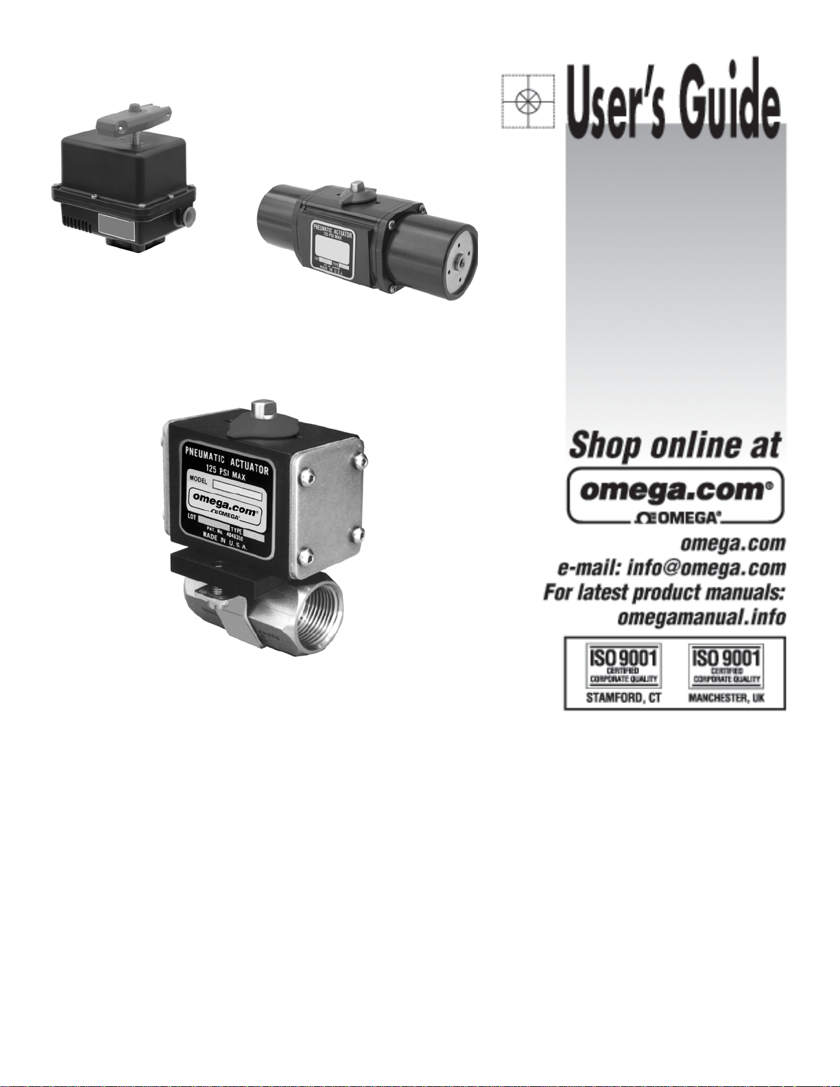
BVE80
BVPS80
BVP80
BVP80, BVPS80 & BVE80 Series
Pneumatically & Electrically Actuated
Barstock Ball Valves
Page 2
2
Page 3
Ball Valve - MATERIALS OF CONSTRUCTION
BODY : Brass - ASTM B-16, or 316 Stainless S teel -
ASTM A276
BALL AND STEM: 316 Stainless Steel
SEATS AND STEM SEAL: Glass Reinforced P.T.F.E.
Ball Valve - CONNECTION / STYLE
SIZES
Pipe / N.P.T .F. 1/4” - 2”
(
Dryseal National Pipe T aper)
Ball Valve - RATINGS
TEMPERA TURE: -50 F to 450 F
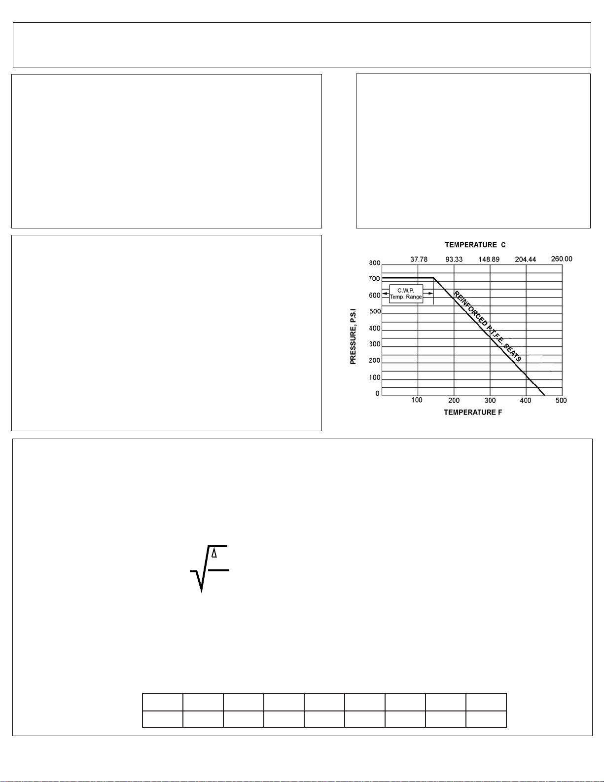
(also see Pressure T emperature Chart)
PRESSURE: 720 p.s.i. C.W.P. (Cold Working Pressure
to 150 F)
(also see Pressure T emperature Chart)
VACUUM: 20 Micron
SATURATED STEAM: 150 p.s.i.
Ball Valve - FLOW CHARACTERISTICS
The approximate flow rate through a valve can be calculated as follows:
where; Q = flow rate in gallons (U.S. Std.) per minute
Cv = valve constant
P = pressure drop across the valve in pounds per square inch
G = specific gravity of the media of relative to water
Note: The values derived from the flow equation are for estimating purposes only . Product variances or
systemic factors may alter actual performance.
BVP80, BVPS80 & BVE80 Series Ball Valves
P
Q = Cv
G
eziS4/18/32/14/31 4/1-12/1-12
vC5.55.5821236428021
3
Page 4

BVP80 & BVPS80 Pneumatic Actuators - MATERIALS OF CONSTRUCTION
BVP80 & BVPS80 Pneumatic Actuators - RATINGS / SPECIFICATIONS
TEMPERA TURE: -20 F to 350 F
AIR SUPPLY: 60 - 125 psi air. Sufficient air delivery must be available at the actuator to ensure dependable
operation. The following precautions should be observed: Air supply should be clean and free of moisture.
When dirty or wet air is a problem; a filter / separator should be specified; these units are most effective when
installed as closely as possible to the actuator. A filter, when used, should permit a minimum flow of 4 scfm at an
upstream pressure of 60 psi. Eliminate severe restrictions to air flow (certain solenoid valves & fittings). The
most restricted passage must have an area no smaller than .012 inches square, the area of 1/8” diameter
orifice. If more than a single actuator is to be supplied by an individual pilot, the minimum passage requirement
applies per actuator.
TUBING: For short runs up to 5 feet 5/32” I.D. is suitable, 1/4” I.D. will serve up to 30 feet. For longer runs,
use 3/8” I.D. or larger.
DUTY CYCLE: 100% CYCLE TIME: (To Open or Close) Approximately 1/2 to 1 second*
* - Dependent upon actuator model, air pressure and delivery
AIR SUPPLY CONNECTION: 1/8” NPT
ELECTRICAL CONNECTION: Mini-DIN by Wire Strain Relief
ELECTRIC: Standard 120VAC Coil;
Wattage: 5
Class: F Continuous Duty
Protection: IP65 (with connector) Dust-tight, Water Resistant
BVP80 & BVPS80 Pneumatic Actuators- MAINTENANCE
Omega BVP70 & BVPS70 Series Pneumatic Actuators are designed to be maintenance free and normally are
replaced vs. repaired.
BVP80 & BVPS80 Series Pneumatic Actuators
BODY : Aluminium with P.T . F .E. Impregnated Hard Anodized Sufaces
EXTERNAL HARDWARE: (Pinion Shaft, Driver, End Caps) 300 Series Stainless Steel
EXTERNAL TRIM: 300 Series Stainless Steel
PILOT VALVE
SPOOL: 18-8 Stainless Steel SEALS: Niltrile / FKM
HARDWARE: 18-8 Stainless Steel COIL / BODY : GF Nylon / Polymide 66
4
Page 5
BVE80 Series Electric Actuators
BVE80 Electric Actuator- MATERIALS OF CONSTRUCTION
ENCLOSURE: Nylon Resin Cover, P.T.F.E. Coated Cast Aluminum Base
SHAFT: 18-8 Stainless Steel
EXTERNAL TRIM: 300 Series Stainless Steel
RATINGS / SPECIFICATIONS
TEMPERA TURE: 40 F to 150 F
MOTOR: Reversing, Brushless, Capacitor-Run with Auto-Reset Thermal Overload Protection.
GEAR TRAIN: Permanently Lubricated, Maintenance Free
POWER: 120VAC 50/60 Hz Single Phase
PORTS: (2) 1/2” N.P.T. Conduit
CYCLE TIME: 6 Seconds
DUTY CYCLE: 1/4” - 1” Sizes;100% 1-1/4” - 2” Sizes; 75%
OVERRIDE: Manual - Fold Out Lever Handle
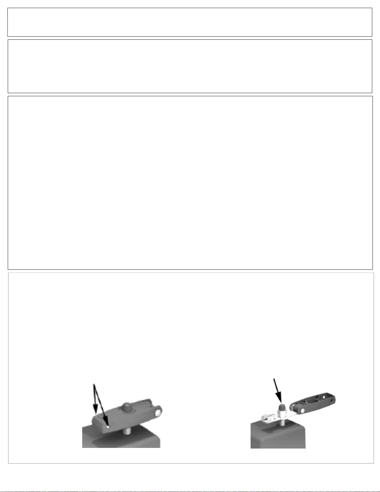
MANUAL OVERRIDE OPERATION
The push-button manual override system allows the user to easily disengage the electric drive gear train for
manual operation of the actuator. All external power must be off prior to using the manual override feature. Th e
actuator manual override handle can be used in the closed or open (lever extended) position to provide additional leverage. To open the handle, pinch the Lever Release Buttons and pull up. Press down the manual
override button (atop the center) and turn the handle to manually open or close the actuated valve assembly . T o
reengage the drive train, release the override button and turn the handle until the manual override button ‘clicks’
signaling the re-engagement of the drive train. The manual override lever handle can then be closed.
Lever Release Buttons
5
Manual Override Button
Page 6

Ball Valve - INSTALLATION INSTRUCTIONS
The following serves as a guideline for those experienced in pipe joint makeup. Otherwise, services of a
certified pipe fitter should be utilized for installation.
1. Ensure that both the male pipe and female valve threads are free from dirt, debris and corrosion. Wire
brushing of the male pipe threads is recommended to ensure a good metal-to-metal joint.
2. Apply a good quality thread lubricant (pipe dope) on the male threads. Lubricant reduces friction when
pulling up the pipe joint. Note, thread lubricant is not intended to seal the joint and will not compensate for
poor quality male pipe or fitting threads.
3. Turn the female valve threads onto the male pipe threads by hand. Upon free engagement of the
threads, continue to turn the valve as far up as it will go (by hand). With the use of a wrench continue to
tighten the valve onto the pipe. The pipe joint seal should occur within 1 to 3 turns after wrenching begins.
Care should be taken not to exceed 3 turns in which damage to the threads can occur .
4. The pipe joint should be tested for leakage to ensure the pipe joint has been achieved.
BVP80, BVPS80 & BVE80 Series Installation Instructions
Pneumatic Actuator - INSTALLATION INSTRUCTIONS
1. Att ached air supply to 1/8” NPT air inlet on integral pilot / solenoid valve.
2. The coil is equipped with a DIN x Strain electrical connector. To wire the connector, remove the center
mounting screw and, with a small screwdriver, pry the inner element from the body of the connector to expose
the terminal blocks inside. Route the wire through the hub of the connector. Loosen the sealing nut and ensure
the wire insulation passes through the rubber grommet inside the hub. Affix the wires to the appropriate terminal block. Retighten sealing nut to secure the wire and provide a seal.
Electric Actuator - INSTALLATION INSTRUCTIONS
1. Unlatch and open the override handle to access the handle nut. Remove nut with 3/4” wrench.
2. Remove eight (8) socket head screws with 4mm hex wrench. Remove cover by pulling straight up.
3. Route the wire to be terminated through conduit hub and up through the access space to the terminal block.
Strip insulation back 1/4”, insert the stripped ends directly into the proper terminal clamp s and tighten screws.
All internal connections are labeled in the diagram, see Page 7.
4. Att ach grounding wire to green screw that is located on top of conduction bar.
5. Verify that cover o-ring is properly seated in groove. Replace cover and screws.
6
Page 7
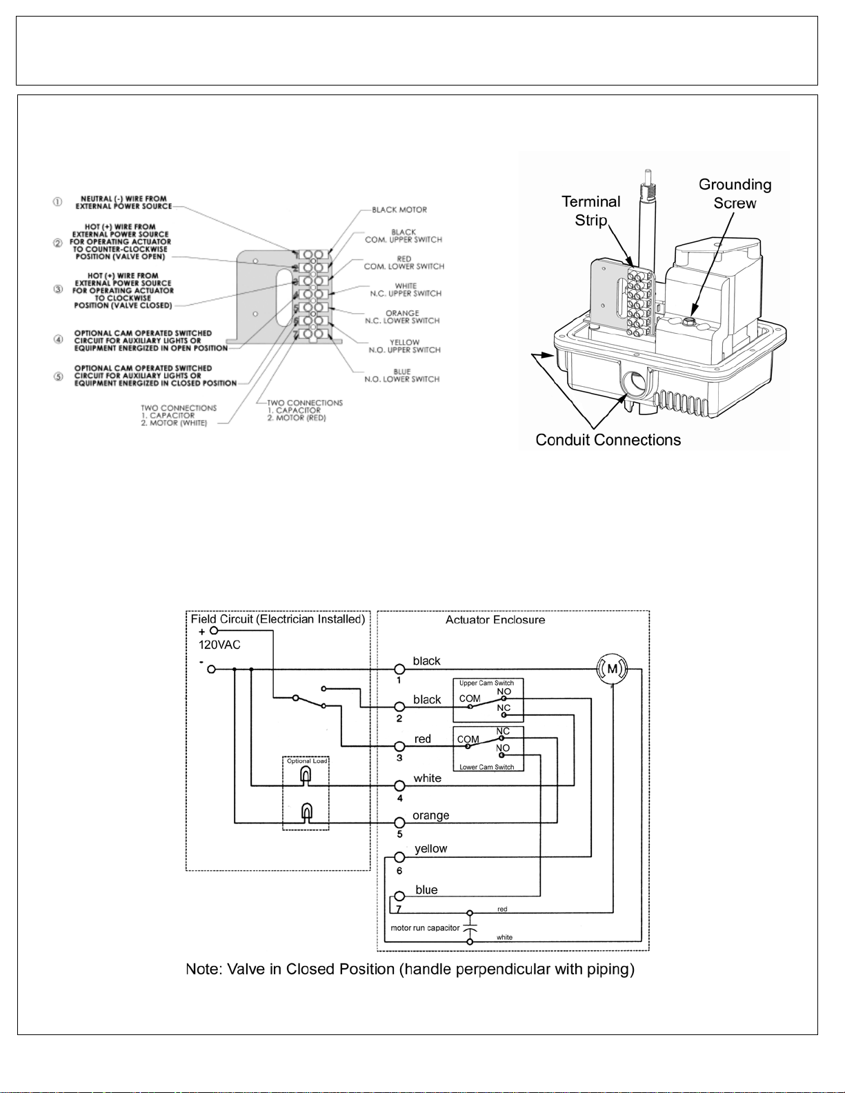
Electric Actuator - INSTALLATION INSTRUCTIONS (continued)
BVP70, BVPS70 & BVE70 Series Installation Instructions
120AC Wiring Schematic
7
Page 8
Ball Valve - MAINTENANCE
The BVP80, BVPS80 & BVE80 Series utilizes our self compensating stem seal design. This design automatically compensates for wear as well as thermal expansion and contraction resulting in a leak tight, maintenance free, service life.
Once the stem seal has worn beyond the compensation afforded by the Belleville springs adjustment of the
stem nut may enable valve to be returned to service. Holding the ‘flats’ of the stem, tighten the stem nut until
Belleville springs become fully compressed (flattened); the torque required to tighten the nut further increases
sharply when this point is reached. Do not tighten the stem nut beyond this point to avoid damage of the stem
seal.
BVP80, BVPS80 & BVE80 Series Maintenance Instructions
& Dimensions
Actuator - MAINTENANCE
The BVP80, BVPS80 & BVE80 Series actuators are maintenance free.
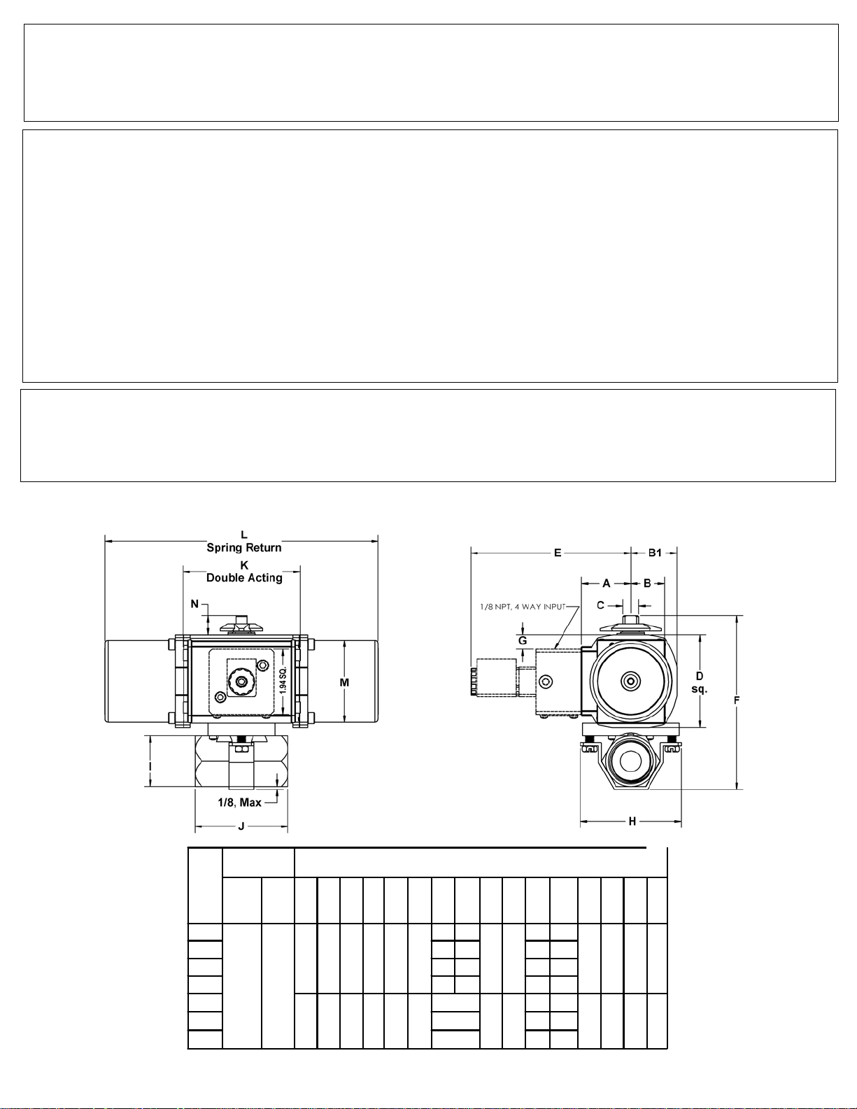
BVP80 & BVPS80 Series Dimensions
Actuator
Valve
Size
1/4, 3/8
1/2 4.85 4.70 1.18 2.61
3/4 5.16 5.01 1.50 2.94
1-1/4
Model
Spring
Double
Return
ActingDAA
SR
BVPS80
Spring
Return
BVP80
Double
Acting
1 5.66 5.51 2.00 3.32
2 8.43 3.00 4.57
BDAB1
SR
1.46 1.00 1.37 .31
1.87 1.55 2.02 .50
Approximate Dimensions, Inches
4.76
5.01
FSRF
DA
4.66 4.51
7.55
.42
SR
.27
DA
1.11 4.75
CDE
2.75
SR
3.06
DA
3.90
SR
4.50
DA
8
GH I J K LMN
1.00 2.18
3.00
2.12 3.70
3.48 8.13 2.44 .57
11.-
5.46
3.50 .821-1/2 8.08 2.62 4.25
22
Page 9
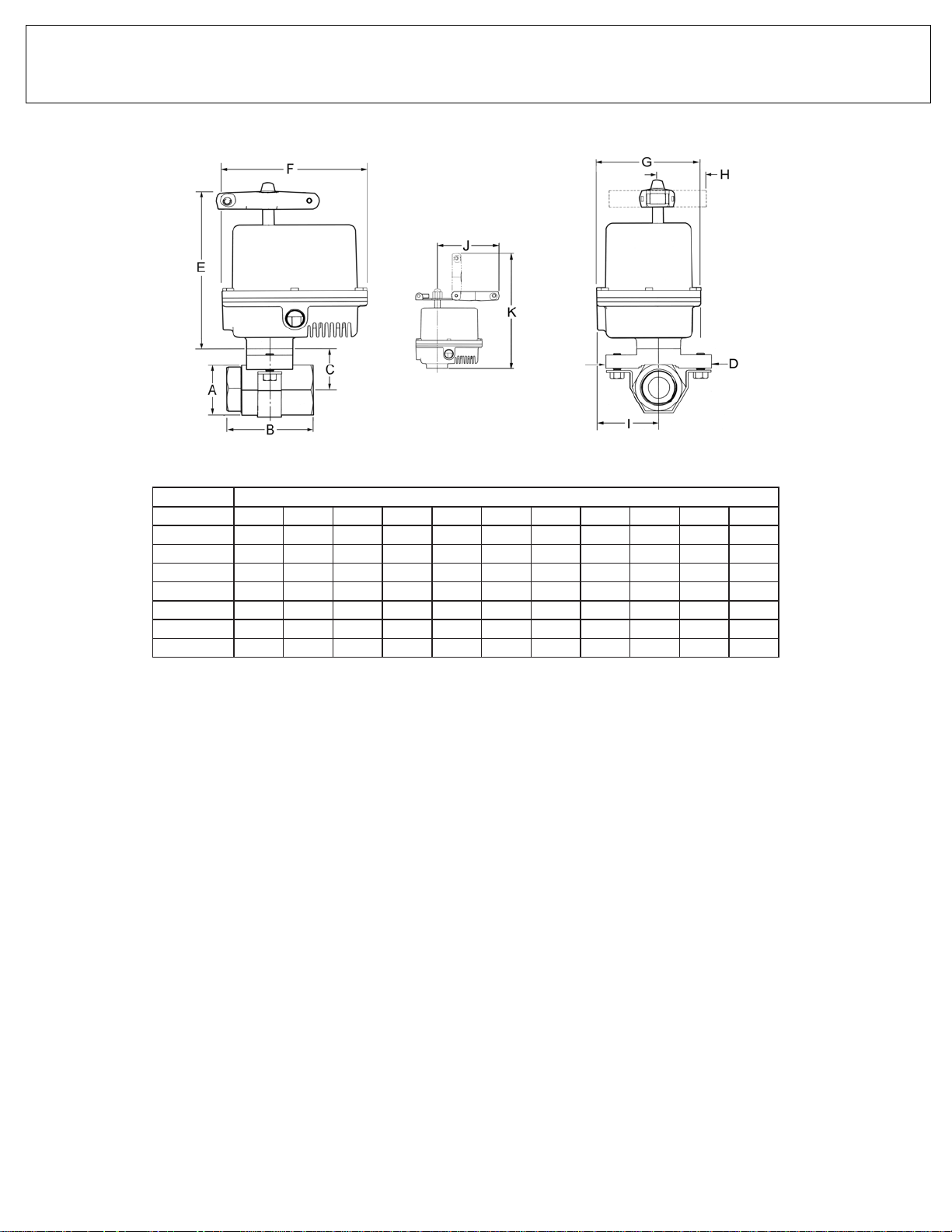
BVE80 Series Dimensions
sehcnI-snoisnemiD
eziSevlaVABCDEFGHIJK
8/3&4/100.122.251.100.347.652.657.432.287.277.553.01
2/181.116.242.100.347.652.657.432.287.277.553
4/305.149.204.100.347.652.657.432.287.277.553.01
149.123.326.100.347.652.657.432.287.277.553.01
4/1-121.207.367.108.442.752.657.43
2/1-126.252.420.208.442.752.657.432.287.277.558.01
200.375.412.208.442.752.657.432.287.277.558.01
2.287.277.558.01
.01
9
Page 10
10
Page 11
11
M-4189/0512
 Loading...