

Page 1
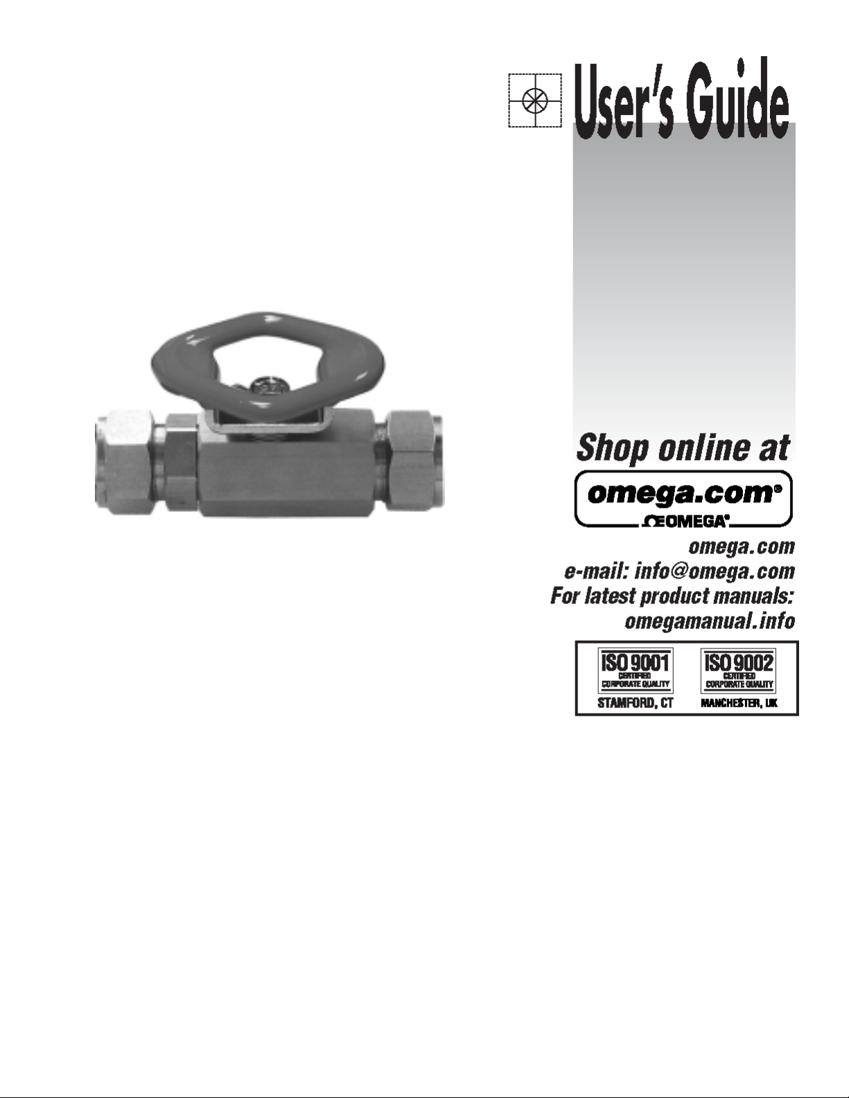
BV70 Series
Premium Quality Tube Compression End
Style Bar Stock Ball Valves
Page 2
2
Page 3

MATERIALS OF CONSTRUCTION
CONNECTION / STYLE SIZES
BODY: Brass - ASTM B-16, or 316 Stainless Steel -
ASTM A276
BALL AND STEM: 316 Stainless Steel
SEATS AND STEM SEAL: Glass Reinforced
P.T.F.E. (Teflon )
RATINGS
TEMPERATURE: -50 F to 450 F
(also see Pressure Temperature Chart)
PRESSURE: 1000 p.s.i. C.W.P. (Cold Working
Pressure to 150 F)
(also see Pressure Temperature Chart)
Tube / Compresssion 1/4” - 1”
VACUUM: 20 Micron
SATURATED STEAM: 150 p.s.i.
FLOW CHARACTERISTICS
The approximate flow rate through a valve can be calculated as follows:
P
Q = Cv
G
where; Q = flow rate in gallons (U.S. Std.) per minute
Cv = valve constant
P = pressure drop across the valve in pounds per square inch
G = specific gravity of the media of relative to water
Note: The values derived from the flow equation are for estimating purposes only. Product variances
or systemic factors may alter actual performance.
3
Page 4

INSTALLATION INSTRUCTIONS
Tube (initial assembly):
1. Ensure the tube end is square and free from burrs, nicks, scratches and debris.
2. Loosen the NUT by turning it counter-clockwise one turn. Insert the tube though the NUT and
FERRULES until it sits against the internal VALVE SHOULDER. Tighten the NUT (clock-wise) hand
tight. Continue tightening the NUT with a wrench for 1 to 1-1/4 turns or until snug.
Note: for re-assembly, after initial assembly, approximately 1/4 turn with wrench is generally required
to re-tighten.
MAINTENANCE
The BV70 Series utilizes our self compensating stem seal design. This design automatically compensates for wear as well as thermal expansion and contraction resulting in a leak tight, maintenance free,
service life.
Once the stem seal has worn beyond the compensation afforded by the Belleville springs adjustment
of the stem nut may enable valve to be returned to service. Holding the ‘flats’ of the stem, tighten the
stem nut until Belleville springs become fully compressed (flattened); the torque required to tighten the
nut further increases sharply when this point is reached. Do not tighten the stem nut beyond this point
to avoid damage of the stem seal.
DIMENSIONS
Tub e
Size OD
1/4 3.72 1.58 .50 2.31 .19 9/16
3/8 3.70 1.58 .50 2.31 .28 11/16
1/2 3.94 1.58 .50 2.31 .36 7/8
3/4 4.17 1.67 .59 3.41 .49 1-1/8
1 4.92 1.91 .75 3.41 .62 1-1/2
Dimensions - Inches
ABCDE F
4
Page 5

5
Page 6

6
M-4058/0405
 Loading...